WO2022163668A1 - 蓄電装置 - Google Patents
蓄電装置 Download PDFInfo
- Publication number
- WO2022163668A1 WO2022163668A1 PCT/JP2022/002746 JP2022002746W WO2022163668A1 WO 2022163668 A1 WO2022163668 A1 WO 2022163668A1 JP 2022002746 W JP2022002746 W JP 2022002746W WO 2022163668 A1 WO2022163668 A1 WO 2022163668A1
- Authority
- WO
- WIPO (PCT)
- Prior art keywords
- power storage
- pair
- tray
- storage element
- axis direction
- Prior art date
- Legal status (The legal status is an assumption and is not a legal conclusion. Google has not performed a legal analysis and makes no representation as to the accuracy of the status listed.)
- Ceased
Links
Images



Classifications
-
- H—ELECTRICITY
- H01—ELECTRIC ELEMENTS
- H01G—CAPACITORS; CAPACITORS, RECTIFIERS, DETECTORS, SWITCHING DEVICES, LIGHT-SENSITIVE OR TEMPERATURE-SENSITIVE DEVICES OF THE ELECTROLYTIC TYPE
- H01G11/00—Hybrid capacitors, i.e. capacitors having different positive and negative electrodes; Electric double-layer [EDL] capacitors; Processes for the manufacture thereof or of parts thereof
- H01G11/10—Multiple hybrid or EDL capacitors, e.g. arrays or modules
-
- H—ELECTRICITY
- H01—ELECTRIC ELEMENTS
- H01G—CAPACITORS; CAPACITORS, RECTIFIERS, DETECTORS, SWITCHING DEVICES, LIGHT-SENSITIVE OR TEMPERATURE-SENSITIVE DEVICES OF THE ELECTROLYTIC TYPE
- H01G11/00—Hybrid capacitors, i.e. capacitors having different positive and negative electrodes; Electric double-layer [EDL] capacitors; Processes for the manufacture thereof or of parts thereof
- H01G11/78—Cases; Housings; Encapsulations; Mountings
-
- H—ELECTRICITY
- H01—ELECTRIC ELEMENTS
- H01M—PROCESSES OR MEANS, e.g. BATTERIES, FOR THE DIRECT CONVERSION OF CHEMICAL ENERGY INTO ELECTRICAL ENERGY
- H01M50/00—Constructional details or processes of manufacture of the non-active parts of electrochemical cells other than fuel cells, e.g. hybrid cells
- H01M50/20—Mountings; Secondary casings or frames; Racks, modules or packs; Suspension devices; Shock absorbers; Transport or carrying devices; Holders
- H01M50/204—Racks, modules or packs for multiple batteries or multiple cells
-
- H—ELECTRICITY
- H01—ELECTRIC ELEMENTS
- H01M—PROCESSES OR MEANS, e.g. BATTERIES, FOR THE DIRECT CONVERSION OF CHEMICAL ENERGY INTO ELECTRICAL ENERGY
- H01M50/00—Constructional details or processes of manufacture of the non-active parts of electrochemical cells other than fuel cells, e.g. hybrid cells
- H01M50/20—Mountings; Secondary casings or frames; Racks, modules or packs; Suspension devices; Shock absorbers; Transport or carrying devices; Holders
- H01M50/204—Racks, modules or packs for multiple batteries or multiple cells
- H01M50/207—Racks, modules or packs for multiple batteries or multiple cells characterised by their shape
- H01M50/209—Racks, modules or packs for multiple batteries or multiple cells characterised by their shape adapted for prismatic or rectangular cells
-
- H—ELECTRICITY
- H01—ELECTRIC ELEMENTS
- H01M—PROCESSES OR MEANS, e.g. BATTERIES, FOR THE DIRECT CONVERSION OF CHEMICAL ENERGY INTO ELECTRICAL ENERGY
- H01M50/00—Constructional details or processes of manufacture of the non-active parts of electrochemical cells other than fuel cells, e.g. hybrid cells
- H01M50/20—Mountings; Secondary casings or frames; Racks, modules or packs; Suspension devices; Shock absorbers; Transport or carrying devices; Holders
- H01M50/244—Secondary casings; Racks; Suspension devices; Carrying devices; Holders characterised by their mounting method
-
- H—ELECTRICITY
- H01—ELECTRIC ELEMENTS
- H01M—PROCESSES OR MEANS, e.g. BATTERIES, FOR THE DIRECT CONVERSION OF CHEMICAL ENERGY INTO ELECTRICAL ENERGY
- H01M50/00—Constructional details or processes of manufacture of the non-active parts of electrochemical cells other than fuel cells, e.g. hybrid cells
- H01M50/20—Mountings; Secondary casings or frames; Racks, modules or packs; Suspension devices; Shock absorbers; Transport or carrying devices; Holders
- H01M50/289—Mountings; Secondary casings or frames; Racks, modules or packs; Suspension devices; Shock absorbers; Transport or carrying devices; Holders characterised by spacing elements or positioning means within frames, racks or packs
Definitions
- the present invention relates to a power storage device that includes a power storage element and a tray on which the power storage element is placed.
- Patent Literature 1 discloses a secondary battery device (power storage device) in which the lower ends of battery cells (power storage elements) are placed in engagement grooves of a lower case (tray). It is
- the power storage device with the above-described conventional configuration has the problem that it has not been possible to reduce the size or weight.
- the conventional power storage device disclosed in Patent Document 1 has a structure in which the lower ends of the power storage elements are placed in a tray, and the tray covers the entire lower ends of the power storage elements. are placed in Therefore, in the above-described conventional power storage device, the tray occupies a relatively large proportion, and it has not been possible to reduce the size or weight of the device.
- the present invention was made by the inventors of the present application by newly paying attention to the above problem, and an object of the present invention is to provide a power storage device that can be reduced in size or weight.
- a power storage device is a power storage device including a power storage element having a side surface extending in a first direction, and a tray on which the power storage element is placed, wherein the tray extends in the first direction.
- a pair of first side walls arranged at positions sandwiching the power storage element in and protruding from the pair of first side walls in a direction approaching each other in the first direction and extending in a second direction intersecting the first direction a pair of bottom walls extending, the pair of bottom walls being arranged in a third direction crossing the first direction and the second direction of the side surface of the power storage element; Both ends in one direction are placed and fixed.
- the power storage device of the present invention it is possible to reduce the size and weight.
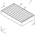
- FIG. 1 is a perspective view showing the appearance of a power storage device according to an embodiment.
- FIG. 2 is an exploded perspective view showing each component when the power storage device according to the embodiment is exploded.
- FIG. 3 is a perspective view showing a configuration of a spacer and a first adhesive body arranged between power storage elements according to the embodiment.
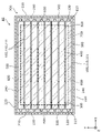
- FIG. 4 is a cross-sectional view showing a configuration of adhesion of a plurality of power storage elements within the tray according to the embodiment.
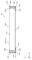
- FIG. 5 is a cross-sectional view showing a configuration of adhesion of a plurality of power storage elements within the tray according to the embodiment.
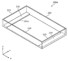
- FIG. 6 is a perspective view showing a configuration of a tray according to Modification 1 of the embodiment.
- FIG. 7 is a cross-sectional view showing a configuration of a power storage device including power storage elements according to Modification 2 of the embodiment.
- FIG. 8 is a diagram illustrating an example of the effects of the power storage device according to Modification 2 of the embodiment.
- a power storage device is a power storage device including a power storage element having a side surface extending in a first direction, and a tray on which the power storage element is placed, wherein the tray extends in the first direction.
- a pair of first side walls arranged at positions sandwiching the power storage element in and protruding from the pair of first side walls in a direction approaching each other in the first direction and extending in a second direction intersecting the first direction a pair of bottom walls extending, the pair of bottom walls being arranged in a third direction crossing the first direction and the second direction of the side surface of the power storage element; Both ends in one direction are placed and fixed.
- the tray has a pair of bottom walls that protrude toward each other from a pair of first side walls that sandwich the power storage element in the first direction and extend in the second direction. , both ends in the first direction of the side surface extending in the first direction of the storage element are placed and fixed. That is, the tray is not provided with a bottom wall on which the entire side surface of the storage element is placed, but is provided with a pair of bottom walls on which both end portions of the side surface of the storage element are placed. In addition, by fixing both end portions of the side surfaces of the storage element to the pair of bottom walls, the storage element reinforces the tray.
- the tray is configured to support the power storage element by the pair of bottom walls, and assuming that the strength of the tray is weakened by this, the power storage element is fixed to the pair of bottom walls to reinforce the tray. .
- the ratio of the tray to be occupied by the tray can be reduced compared to the case where the tray is provided with a bottom wall on which the entire side surface of the power storage element is placed, so that the size and weight of the power storage device can be reduced.
- the electric storage element has a container having the side surface and electrode terminals protruding from the container in the first direction, and the pair of bottom walls are arranged at both ends of the side surface of the container in the first direction. may be placed and fixed.
- the electric storage element has a container having a side surface extending in the first direction and electrode terminals projecting from the container in the first direction, and both ends of the side surface of the container in the first direction are It is placed and fixed on a pair of bottom walls.
- the vertically long storage element extending in the first direction is laid down and fixed to the pair of bottom walls.
- the electricity storage element has a long side surface facing the second direction and a short side surface facing the third direction, and the pair of bottom walls are arranged on the short side surface in the third direction, Both ends of the short sides in the first direction may be placed and fixed.
- the electric storage element has long side surfaces facing in the second direction and short side surfaces facing in the third direction, and both ends in the first direction of the short side surfaces of the electric storage element It is placed and fixed on the bottom wall.
- the long sides of the energy storage elements face the second direction and the short sides face the third direction, so that more energy storage elements can be arranged in the second direction.
- the tray can be reinforced by the power storage element, so that a configuration for reducing the size or weight of the power storage device can be realized.
- a plurality of power storage elements arranged in the second direction may be placed and fixed on the tray, and the plurality of power storage elements may be fixed via at least one of a spacer and an adhesive.
- the plurality of power storage elements arranged in the second direction are placed and fixed on the tray in a state of being fixed via at least one of the spacer and the adhesive.
- the plurality of power storage elements are placed on the tray and fixed.
- the tray can be reinforced by the power storage element, so that a configuration for reducing the size or weight of the power storage device can be realized.
- the tray has a pair of second side walls arranged at positions sandwiching the power storage element in the second direction, and the power storage element is at least one of the pair of first side walls and the pair of second side walls. It may be fixed to one side wall.
- the electric storage element is fixed to at least one of the pair of first side walls and the pair of second side walls of the tray that sandwiches the electric storage element in the first direction and the second direction.
- the power storage element and the tray are more integrated.
- the tray can be reinforced by the power storage element, so that a configuration for reducing the size or weight of the power storage device can be realized.
- the electric storage element may have a projecting portion projecting in the third direction and arranged between the pair of bottom walls.
- the power storage element can be easily positioned with respect to the tray by providing the power storage element with the projecting portion arranged between the pair of bottom walls of the tray. As a result, it is possible to prevent the power storage device from becoming unfixed from the pair of bottom walls of the tray, and to maintain the reinforcement of the tray by the power storage device. can do.
- the extending direction of the container of the storage element, the direction in which the pair of electrode terminals of the storage element are aligned (protruding direction), the direction in which the pair of first side walls of the tray are aligned (facing direction), and the pair of trays The extension direction of the second side wall and the pair of second bottom walls of the tray, and the alignment direction (protrusion direction) of the pair of first bottom walls of the tray are defined as the X-axis direction.
- the direction (facing direction) or the direction in which the pair of second bottom walls are arranged (protruding direction) is defined as the Y-axis direction.
- the direction in which the short sides of the storage element face each other, the direction in which the storage element and the pair of bottom walls are aligned, or the vertical direction is defined as the Z-axis direction.
- X-axis direction, Y-axis direction, and Z-axis direction are directions that cross each other (perpendicularly in this embodiment). Although the Z-axis direction may not be the vertical direction depending on the mode of use, the Z-axis direction will be described below for convenience of explanation.
- the positive direction of the X-axis indicates the direction of the arrow on the X-axis
- the negative direction of the X-axis indicates the direction opposite to the positive direction of the X-axis.
- the Y-axis direction and the Z-axis direction may also be referred to as the first direction
- the Y-axis direction may also be referred to as the second direction
- the Z-axis direction or the Z-axis negative direction may also be referred to as the third direction.
- expressions indicating relative directions or orientations such as parallel and orthogonal include cases where they are not strictly the directions or orientations.
- two directions are orthogonal not only means that the two directions are completely orthogonal, but also substantially orthogonal, that is, for example, a difference of about several percent It is also meant to include
- FIG. 1 is a perspective view showing the appearance of power storage device 10 according to the present embodiment.
- FIG. 2 is an exploded perspective view showing each component when power storage device 10 according to the present embodiment is exploded.
- the power storage device 10 is a device that can charge electricity from the outside and discharge electricity to the outside, and has a substantially rectangular parallelepiped shape in the present embodiment.
- the power storage device 10 is a battery module (assembled battery) used for power storage or power supply.
- the power storage device 10 is used for driving mobile bodies such as automobiles, motorcycles, water crafts, ships, snowmobiles, agricultural machinery, construction machinery, or railroad vehicles for electric railways, or for starting engines. Used as a battery or the like. Examples of such vehicles include electric vehicles (EV), hybrid electric vehicles (HEV), plug-in hybrid electric vehicles (PHEV), and gasoline vehicles. Examples of railway vehicles for the electric railway include electric trains, monorails, linear motor cars, and hybrid trains having both diesel engines and electric motors.
- the power storage device 10 can also be used as a stationary battery or the like for home or business use.
- the power storage device 10 includes a plurality of power storage elements 100 and a tray 200 on which the plurality of power storage elements 100 are placed.
- the power storage device 10 also includes a bus bar that connects the power storage elements 100 in series or in parallel, but illustration and description thereof are omitted.
- the power storage device 10 includes restraining members (end plates, side plates, etc.) that restrain the plurality of power storage elements 100, a busbar frame that positions the busbars, a lid that closes the opening of the tray 200, an external An external terminal connected to a bus bar or the like, and an electric device such as a circuit board and a relay for monitoring or controlling the charge state and discharge state of the storage element 100 may also be provided.
- the storage element 100 is a secondary battery (single battery) capable of charging and discharging electricity, and more specifically, a non-aqueous electrolyte secondary battery such as a lithium ion secondary battery.
- Energy storage element 100 has a long and flat rectangular parallelepiped shape (square shape) extending in the X-axis direction (first direction), and a plurality of (eight in the present embodiment) energy storage elements 100 extend in the Y-axis direction. (second direction) are arranged side by side.
- the power storage element 100 has a long shape in the X-axis direction, for example, about 500 to 1500 mm in length in the X-axis direction, about several tens of mm in thickness in the Y-axis direction, and about 50 to 100 mm in height in the Z-axis direction. have.
- the power storage element 100 is not limited to a non-aqueous electrolyte secondary battery, and may be a secondary battery other than a non-aqueous electrolyte secondary battery, or may be a capacitor.
- the power storage element 100 may be a primary battery that can use stored electricity without being charged by the user, instead of a secondary battery.
- the storage element 100 may be a battery using a solid electrolyte.
- the storage element 100 may be a pouch-type storage element.
- the shape of the electric storage element 100 is not limited to a rectangular parallelepiped shape, and may be a polygonal prismatic shape, an elongated cylindrical shape, an elliptical shape, a circular shape, or the like other than the rectangular parallelepiped shape.
- the number of power storage elements 100 is not particularly limited, and a configuration in which only one power storage element 100 is arranged, or a configuration in which about 100 or more power storage elements 100 are arranged side by side may be employed.
- the storage element 100 has a container 110 and a pair of electrode terminals 120 (positive electrode side and negative electrode side). A pair of (positive electrode side and negative electrode side) current collectors (not shown) are accommodated.
- An electrolytic solution non-aqueous electrolyte
- gaskets are arranged between the electrode terminals 120 and current collectors and the container 110. omitted.
- the type thereof is not particularly limited as long as it does not impair the performance of the electric storage element 100, and various kinds can be selected.
- the electric storage element 100 may have spacers arranged on the side or below the electrode body, an insulating film that wraps the electrode body, and the like. Furthermore, an insulating film (shrink tube or the like) covering the outer surface of the container 110 may be arranged around the container 110 .
- the material of the insulating film is not particularly limited as long as it can ensure the insulation required for the storage element 100.
- any insulating resin that can be used for the tray 200 described later epoxy resin, Kapton, Examples include Teflon (registered trademark), silicon, polyisoprene, and polyvinyl chloride.
- the container 110 is a cuboid-shaped (square or box-shaped) case extending in the X-axis direction (first direction).
- the material of the container 110 is not particularly limited, and can be, for example, a weldable metal such as stainless steel, aluminum, aluminum alloy, iron, or plated steel plate, but resin can also be used.
- the strength of the tray 200 on which the container 110 is arranged is stronger than the strength of the tray 200 alone (the strength of the tray 200 before the container 110 is arranged). is preferred.
- the container 110 preferably has higher strength (rigidity) than the tray 200 .
- the container 110 is preferably made of a material having a higher strength (rigidity) than the tray 200 or is structurally formed with a higher strength (rigidity) than the tray 200 .
- the container 110 is provided with a gas discharge valve that releases the pressure when the pressure inside the container 110 is excessively increased, and an injection part for injecting an electrolytic solution into the inside of the container 110.
- the above stiffness is the stiffness against torsion or bending.
- the container 110 is made of a thin metal plate (aluminum or the like). , the stiffness as a whole is increased.
- the storage device 100 (container 110) is structurally configured to have high rigidity against torsion or bending.
- the tray 200 is formed of a metal plate (iron, stainless steel, etc.) having a certain thickness, but the thickness is limited for weight reduction, and the tray 200 is formed long (for example, over 1 m). , it becomes a configuration that is easy to bend.
- the tray 200 is composed of four side frames, so the rigidity against torsion is particularly low.
- the tray 200 can be reinforced by arranging the power storage element 100 including the box-shaped (long prismatic) container 110 on the tray 200 .
- the tray 200 can be reinforced by arranging the power storage element 100 including the box-shaped (long prismatic) container 110 on the tray 200 .
- power storage device 10 including long tray 200 can be configured to have high rigidity against torsion or bending.
- the container 110 has a pair of long side surfaces 111 extending in the X-axis direction (first direction) on both side surfaces in the Y-axis direction, and a pair of short side surfaces 111 extending in the X-axis direction (first direction) on both side surfaces in the Z-axis direction. It has side surfaces 112 and terminal arrangement surfaces 113 on both sides in the X-axis direction.
- the long side surface 111 is a rectangular and planar side surface elongated in the X-axis direction that forms the long side surface of the container 110 and is arranged to face the Y-axis direction (second direction).
- the long side surface 111 is arranged to face the long side surface 111 of the container 110 of the adjacent storage element 100 or the later-described second side wall 220 of the tray 200 in the Y-axis direction.
- the long side 111 is adjacent to the short side 112 and the terminal arrangement surface 113 and has a larger area than the short side 112 .
- the short side surface 112 is a rectangular and planar side surface elongated in the X-axis direction, which forms the short side surface of the container 110, and is arranged to face the Z-axis direction (third direction).
- the short side surface 112 is arranged to face a first bottom wall 230 or a second bottom wall 240 (described later) of the tray 200 in the Z-axis direction.
- the short side 112 is adjacent to the long side 111 and the terminal arrangement surface 113 and has a smaller area than the long side 111 .
- the terminal arrangement surface 113 is a rectangular and planar side surface on which the electrode terminal 120 is arranged, and is arranged facing the X-axis direction (first direction).
- the terminal arrangement surface 113 is arranged to face a first side wall 210 of the tray 200, which will be described later, in the X-axis direction.
- the terminal placement surface 113 is adjacent to the long side 111 and the short side 112 and has a smaller area than the long side 111 and the short side 112 .
- the electrode terminals 120 are terminal members (a positive electrode terminal and a negative electrode terminal) of the storage element 100 arranged in a state of projecting from the container 110 in the X-axis direction (first direction) on both sides of the container 110 in the X-axis direction. That is, one of the pair of electrode terminals 120 is a positive terminal and the other is a negative terminal. Specifically, the electrode terminal 120 in the positive X-axis direction of the container 110 protrudes in the positive X-axis direction from the terminal arrangement surface 113 in the positive X-axis direction. The negative X-direction electrode terminal 120 of the container 110 protrudes in the negative X-axis direction from the negative X-direction terminal arrangement surface 113 .
- the electrode terminal 120 is electrically connected to the positive electrode plate and the negative electrode plate of the electrode body through the current collector.
- the electrode terminal 120 is made of metal for leading electricity stored in the electrode body to the external space of the storage element 100 and for introducing electricity into the internal space of the storage element 100 to store the electricity in the electrode body. It is a member made of The electrode terminal 120 is made of aluminum, an aluminum alloy, copper, a copper alloy, or the like.
- the electrode terminal 120 in the positive direction of the X-axis may be the positive terminal, and the electrode terminal 120 in the negative direction of the X-axis may be the negative terminal.
- the electrode terminal 120 may be the positive terminal, and the electrode terminal 120 in the positive direction of the X-axis may be the negative terminal.
- the electrode assembly is a power storage element (power generation element) formed by laminating a positive electrode plate, a negative electrode plate, and a separator.
- the positive electrode plate is formed by forming a positive electrode active material layer on a positive electrode substrate layer, which is a collector foil made of a metal such as aluminum or an aluminum alloy.
- the negative electrode plate is formed by forming a negative electrode active material layer on a negative electrode substrate layer, which is a collector foil made of a metal such as copper or a copper alloy.
- the active material used for the positive electrode active material layer and the negative electrode active material layer any known material can be appropriately used as long as it can intercalate and deintercalate lithium ions.
- the electrode body is formed by stacking electrode plates (a positive electrode plate and a negative electrode plate) in the Y-axis direction.
- the electrode body includes a wound electrode body formed by winding electrode plates (a positive electrode plate and a negative electrode plate), and a laminated (stacked) electrode formed by stacking a plurality of flat plate-shaped electrode plates.
- the electrode body may have any form, such as a body or a bellows-shaped electrode body in which an electrode plate is folded into a bellows shape.
- the current collectors are conductive current collecting members (positive electrode current collector and negative electrode current collector) that are electrically and mechanically connected to the electrode terminal 120 and the electrode body.
- the positive electrode current collector is made of aluminum or an aluminum alloy, like the positive electrode substrate layer of the positive electrode plate of the electrode body. It is made of an alloy or the like.
- the tray 200 is a box-shaped (rectangular parallelepiped) tray (module case) forming a housing (outer shell) of the power storage device 10, and accommodates a plurality of power storage elements 100 placed thereon.
- the tray 200 is arranged outside the plurality of power storage elements 100, fixes the plurality of power storage elements 100 at predetermined positions, and protects them from impacts and the like.
- the tray 200 is made of, for example, polycarbonate (PC), polypropylene (PP), polyethylene (PE), polyphenylene sulfide resin (PPS), polyphenylene ether (PPE (including modified PPE)), polyethylene terephthalate (PET), polybutylene terephthalate. (PBT), polyether ether ketone (PEEK), tetrafluoroethylene/perfluoroalkyl vinyl ether (PFA), polytetrafluoroethylene (PTFE), polyether sulfone (PES), ABS resin, or composite materials thereof, etc. of insulating material.
- PC polycarbonate
- PP polypropylene
- PE polyethylene
- PPS polyphenylene sulfide resin
- PPE polyphenylene ether
- PET polyethylene terephthalate
- PBT polybutylene terephthalate.
- PBT polybutylene terephthalate.
- PEEK polyether ether ketone
- the tray 200 has a rectangular parallelepiped shape in which the entire surface in the positive Z-axis direction is open and a part of the surface in the negative Z-axis direction is open. It is an enclosing annular housing.
- the tray 200 has a pair of opposing first side walls 210 on both sides in the X-axis direction, and a pair of opposing second side walls 220 on both sides in the Y-axis direction. , a pair of opposing first bottom walls 230 and a pair of opposing second bottom walls 240 .
- the first side wall 210 is a flat and rectangular wall portion extending in the Y-axis direction parallel to the YZ plane and forming a short side surface of the tray 200, sandwiching the power storage element 100 in the X-axis direction (first direction). placed in position.
- the first side wall 210 is adjacent to the second side wall 220 and the first bottom wall 230 and has a smaller outer surface area than the second side wall 220 .
- the first side wall 210 in the positive X-axis direction is arranged so as to face the terminal arrangement surface 113 and the electrode terminals 120 in the positive X-axis direction of the power storage elements 100 .
- a first side wall 210 in the negative X-axis direction is arranged so as to face the terminal arrangement surface 113 in the negative X-axis direction and the electrode terminals 120 of the power storage elements 100 .
- the pair of first side walls 210 sandwich the plurality of power storage elements 100 in the X-axis direction.
- the second side wall 220 is a flat, rectangular wall extending in the X-axis direction parallel to the XZ plane, forming the long side surface of the tray 200, and sandwiching the power storage element 100 in the Y-axis direction (second direction). placed in position.
- the second side wall 220 is adjacent to the first side wall 210 and the first bottom wall 230 and has a larger outer surface area than the first side wall 210 .
- the second side wall 220 in the positive Y-axis direction is arranged to face the long side surface 111 in the positive Y-axis direction of the storage element 100 at the end in the positive Y-axis direction.
- a second side wall 220 in the negative Y-axis direction is arranged to face the long side surface 111 in the negative Y-axis direction of the storage element 100 at the end in the negative Y-axis direction.
- the pair of second side walls 220 sandwich the plurality of power storage elements 100 in the Y-axis direction.
- the tray 200 may have a pair of long side surfaces on both sides in the X-axis direction and a pair of short side surfaces on both sides in the Y-axis direction, depending on the number and shape of the storage elements 100 . That is, the pair of first sidewalls 210 may form the long sides of the tray 200 and the pair of second sidewalls 220 may form the short sides of the tray 200 .
- the first bottom wall 230 is a flat and rectangular wall portion that forms the bottom surface of the tray 200 and extends in the Y-axis direction (the second direction that intersects with the first direction) parallel to the XY plane. is arranged in the Z-axis direction (the third direction intersecting the first direction and the second direction) of the side surface of the .
- the first bottom wall 230 is the wall adjacent to the first side wall 210 .
- the first bottom wall 230 in the positive X-axis direction protrudes in the negative X-axis direction from the first side wall 210 in the positive X-axis direction, and the short side faces in the negative Z-axis direction of the power storage elements 100 112 in the positive direction of the X axis.
- the first bottom wall 230 in the negative X-axis direction protrudes in the positive X-axis direction from the first side wall 210 in the negative X-axis direction, and the negative X-axis direction of the short side surfaces 112 of the plurality of power storage elements 100 in the negative Z-axis direction. are arranged opposite the ends of the direction.
- the pair of first bottom walls 230 protrude from the pair of first side walls 210 toward each other in the X-axis direction (first direction), It is arranged in the Z-axis minus direction (third direction, downward) of both ends. Both ends of the short side surfaces 112 of the plurality of power storage elements 100 in the X-axis direction are placed and supported in contact with the pair of first bottom walls 230 .
- the second bottom wall 240 is a flat and rectangular wall portion that forms the bottom surface of the tray 200 and extends in the X-axis direction (first direction) parallel to the XY plane. (third direction).
- the second bottom wall 240 is the wall adjacent to the second side wall 220 .
- the second bottom wall 240 in the positive Y-axis direction protrudes in the negative Y-axis direction from the second side wall 220 in the positive Y-axis direction, and Z It is arranged to face the short side 112 in the negative direction of the axis.
- the second bottom wall 240 in the negative Y-axis direction protrudes in the positive Y-axis direction from the second side wall 220 in the negative Y-axis direction, and has a short length in the negative Z-axis direction of the storage element 100 at the end in the negative Y-axis direction. It is arranged opposite side 112 .
- the pair of second bottom walls 240 protrude from the pair of second side walls 220 toward each other in the Y-axis direction (second direction), and extend from the short side surfaces 112 of the storage element 100 at both ends in the Y-axis direction. is arranged in the Z-axis negative direction (third direction, downward).
- the short side surfaces 112 of the storage element 100 at both ends in the Y-axis direction are placed and supported in contact with the pair of second bottom walls 240 .
- the tray 200 By providing the tray 200 with the pair of first bottom walls 230 and the pair of second bottom walls 240 in this manner, the tray 200 is formed with a rectangular opening 250 in the central portion of the bottom wall. becomes.
- the pair of second bottom walls 240 has the function of reinforcing the tray 200 because both ends in the X-axis direction are connected to the pair of first bottom walls 230 .
- the power storage element 100 is adhered to other adjacent power storage elements 100 and to the tray 200 .
- adjacent energy storage elements 100 among the plurality of energy storage elements 100 are adhered and fixed.
- a plurality of storage elements 100 and a pair of first side walls 210, a pair of second side walls 220, a pair of first bottom walls 230 and a pair of second bottom walls 240 of tray 200 are adhered and fixed.
- FIG. 3 is a perspective view showing the configuration of the spacer 300 and the first adhesive body 400 arranged between the power storage elements 100 according to this embodiment. Specifically, FIG. 3 shows a configuration in which a spacer 300 and a first adhesive 400 are arranged on one of two adjacent energy storage elements 100 .
- FIG. 4 and FIG. 5 are cross-sectional views showing the configuration of adhesion of a plurality of power storage elements 100 within tray 200 according to the present embodiment.
- FIG. 4 is a cross-sectional view showing the configuration of the power storage device 10 shown in FIG. 1 taken along line IV-IV and parallel to the XY plane as viewed from the positive direction of the Z axis. be.
- FIG. 5 is a cross-sectional view showing the configuration of the power storage device 10 shown in FIG. 1 cut along a plane parallel to the XZ plane through the line VV and viewed from the minus direction of the Y-axis.
- the power storage device 10 has a spacer 300 and a first adhesive 400 in addition to the above configuration. That is, the spacer 300 and the first adhesive 400 are arranged between two adjacent energy storage elements 100 . Specifically, the spacer 300 and the first adhesive body 400 are arranged between the long side surfaces 111 of two adjacent power storage elements 100 . Thereby, the plurality of power storage elements 100 are fixed via at least one of the spacer 300 and the first adhesive body 400 . In this embodiment, the plurality of power storage elements 100 are fixed via both the spacer 300 and the first adhesive 400 . That is, by interposing the spacer 300 and the first adhesive body 400 between two adjacent power storage elements 100 among the plurality of power storage elements 100, the power storage elements 100 are fixed to each other, and the plurality of power storage elements 100 are integrated. become.
- the spacer 300 is a member that is arranged between the long side surfaces 111 of two adjacent power storage elements 100 to separate the long side surfaces 111 from each other.
- four spacers 300 are arranged at both ends in the X-axis direction and both ends in the Z-axis direction of the long side surface 111 of the storage element 100 (that is, the four corners of the long side surface 111).
- the spacer 300 is a double-sided tape and has insulating properties.
- the spacer 300 has adhesive layers on both sides in the Y-axis direction, which adhere to the long side surfaces 111 of the power storage elements 100 .
- the spacer 300 is, for example, a double-sided tape having an adhesive layer provided on both sides of an insulating base material such as a plate-like rectangular resin having a thickness of about 1 mm.
- the first adhesive body 400 is a member that is arranged between the long side surfaces 111 of two adjacent power storage elements 100 and bonds the long side surfaces 111 together.
- the first adhesive 400 is an adhesive that is arranged in the central portion of the long side surface 111 of the power storage element 100 and has insulating properties.
- the adhesive is in a liquid state before being placed (applied) on the long side surface 111 and adheres by becoming solid, or is in a gel state before being placed (applied) on the long side surface 111.
- a solid material such as a hot-melt adhesive can be used.
- the first adhesive body 400 is arranged at a position not overlapping the spacer 300 when viewed from the Y-axis direction.
- the first adhesive body 400 may be arranged on the entire surface of the long side surface 111 where the spacers 300 are not arranged.
- the first adhesive body 400 is preferably arranged apart from the spacer 300 .
- an insulating film such as a shrink tube covering the outer surface of the container 110 is arranged around the container 110, so that the insulation of the electric storage element 100 can be ensured.
- the two storage elements 100 are temporarily fixed with the spacer 300 until the first adhesive 400 hardens.
- the device 100 can be glued.
- the two storage elements 100 can be bonded by temporarily fixing the two storage elements 100 with the spacer 300 and then pouring the first adhesive 400 into the gap between the two storage elements 100 .
- the power storage device 10 in order to fix the power storage device 100 to the tray 200, includes a fixing member 500 and a second adhesive body 600 in addition to the above configuration.
- a plurality of power storage elements 100 arranged in the Y-axis direction (second direction) are placed and fixed on the tray 200 by the fixing member 500 and the second adhesive body 600 .
- the fixing member 500 fixes the power storage element 100 to at least one of the pair of first side walls 210 and the pair of second side walls 220 .
- a plurality of power storage elements 100 are fixed to all side walls of the pair of first side walls 210 and the pair of second side walls 220 .
- both ends of the side surfaces of the plurality of power storage elements 100 in the X-axis direction (first direction) are placed on and fixed to the pair of first bottom walls 230 by the second adhesive body 600 .
- the fixing member 500 is a member that is arranged between the plurality of power storage elements 100 and the side wall of the tray 200 and fixes the power storage element 100 and the side wall of the tray 200 .
- fixing members 500 are arranged around the plurality of power storage elements 100 (on both sides in the X-axis direction and on both sides in the Y-axis direction), and the fixing members 500 connect the periphery of the plurality of power storage elements 100 and the side wall of the tray 200 .
- Fixed the fixing member 500 is an adhesive and has insulating properties. As the adhesive, any adhesive or the like that can be used for the first adhesive body 400 can be used.
- the fixing member 500 is arranged between the terminal arrangement surface 113 of the container 110 of the storage element 100 and the first side wall 210 of the tray 200, and fixes the terminal arrangement surface 113 and the first side wall 210. .
- the fixing member 500 is arranged between the long side 111 of the container 110 of the power storage element 100 and the second side wall 220 of the tray 200 to fix the long side 111 and the second side wall 220 . More specifically, the fixing member 500 is filled (filled) between the terminal arrangement surface 113 and the first side wall 210 over the entire inner surface of the first side wall 210 . The entire inner surface and the terminal arrangement surface 113 are adhered and fixed.
- the fixing member 500 is filled (filled) between the long side surface 111 and the second side wall 220 over the entire inner surface of the second side wall 220 , and is disposed between the entire inner surface of the second side wall 220 and the long side surface 111 . Glue and fix the entire surface of the
- the fixing member 500 is arranged to avoid members such as bus bars (not shown).
- the fixing member 500 is arranged only on a part of the inner surface of the first side wall 210 , and the part of the inner surface and the terminal arrangement surface 113 may be adhered and fixed.
- the fixing member 500 is arranged only on a part of the inner surface of the second side wall 220, and the part of the inner surface and the part of the long side surface 111 may be adhered and fixed.
- the second adhesive body 600 is a member that is arranged between the plurality of power storage elements 100 and the bottom wall of the tray 200 and fixes the power storage elements 100 and the bottom wall of the tray 200 .
- the second adhesive body 600 is arranged between the side surfaces of the plurality of power storage elements 100 in the negative direction of the Z axis and the bottom wall of the tray 200 , and the second adhesive body 600 allows the plurality of power storage elements 100 to adhere to each other.
- the sides and the bottom wall of tray 200 are fixed.
- the second adhesive body 600 is an adhesive and has insulating properties.
- any adhesive or the like that can be used for the first adhesive body 400 can be used.
- the second adhesive body 600 is between the short side surface 112 of the container 110 of the power storage element 100 in the negative Z-axis direction and the pair of first bottom walls 230 and the pair of second bottom walls 240 of the tray 200. and fix the short side 112 with the pair of first bottom walls 230 and the pair of second bottom walls 240 . More specifically, the second adhesive body 600 is arranged by coating or the like over the entire inner surface of the pair of first bottom walls 230 and the pair of second bottom walls 240, and the pair of first bottom walls 230 and the pair of second bottom walls 240 The entire inner surface of the second bottom wall 240 and the short side surface 112 are adhered and fixed. The second adhesive body 600 is arranged only on a part of the inner surfaces of the pair of first bottom walls 230 and the pair of second bottom walls 240, and the part of the inner surfaces and the short side surface 112 are bonded and fixed. You may decide to
- the pair of first bottom walls 230 are arranged in the Z-axis minus direction (third direction) of the short side surface 112 of the container 110 of the storage element 100 , and are arranged in the X-axis direction (first direction) of the short side surface 112 of the container 110 . direction) are placed and fixed. That is, both ends of the short side surface 112 of the power storage element 100 in the X-axis direction are placed in contact with the pair of first bottom walls 230 , and the second adhesive 600 attaches to the pair of first bottom walls 230 . Fixed directly.
- the pair of second bottom walls 240 are arranged in the negative Z-axis direction of the short side surfaces 112 of the storage element 100 at both ends in the Y-axis direction, and the short side surfaces 112 are placed and fixed.
- the short side surfaces 112 of the storage element 100 at both ends in the Y-axis direction are placed in contact with the pair of second bottom walls 240 , and the second adhesive 600 attaches to the pair of second bottom walls 240 . Fixed directly.
- tray 200 protrudes toward each other from a pair of first side walls 210 sandwiching power storage element 100 in the first direction (X-axis direction). It has a pair of first bottom walls 230 extending in the direction (Y-axis direction). Both ends in the first direction of the side surfaces (short side surfaces 112 ) of the storage element 100 extending in the first direction are placed and fixed to the pair of first bottom walls 230 . That is, the tray 200 is provided with a pair of first bottom walls 230 on which both end portions of the side surfaces of the storage element 100 are placed, instead of providing bottom walls on which the entire side surfaces of the storage element 100 are placed.
- the tray 200 is reinforced by the storage element 100 .
- the tray 200 is configured to support the power storage element 100 with the pair of first bottom walls 230, and assuming that the strength of the tray 200 is reduced due to this, the power storage element By fixing 100, the tray 200 is reinforced.
- the tray 200 occupies a smaller proportion than when the tray 200 is provided with a bottom wall on which the entire side surface of the power storage device 100 is placed, so that the size and weight of the power storage device 10 can be reduced. . Since the amount of material used for the tray 200 can be reduced, cost reduction can be achieved.
- the conventional power storage device disclosed in Patent Document 1 has a structure in which the lower ends of the power storage elements are placed in a tray, and the tray covers the entire lower ends of the power storage elements. are placed in Therefore, in the conventional power storage device, when cooling is performed, air cooling is performed by flowing air from above or below, or cooling is performed by pressing a cooling plate such as a water cooling plate against the bottom surface of the power storage element. However, in either case, sufficient cooling cannot be achieved.
- power storage device 10 according to the present embodiment has opening 250 in the bottom wall. Cooling can be performed by pressing a cooling plate for water cooling or the like against the short side surface 112). Thus, in the power storage device 10, the cooling structure is simplified, and an inexpensive and excellent cooling structure can be realized.
- the power storage element 100 has a container 110 having a side surface (short side surface 112) extending in the first direction (X-axis direction) and an electrode terminal 120 protruding from the container 110 in the first direction. Both ends of the side surface in the first direction are placed on and fixed to the pair of first bottom walls 230 . In this manner, the vertically elongated power storage element 100 extending in the first direction is laid down and fixed to the pair of first bottom walls 230 . As a result, the power storage device 100 can reinforce the tray 200, so that a configuration for reducing the size or weight of the power storage device 10 can be realized.
- the power storage element 100 has a long side surface 111 facing in the second direction (Y-axis direction) and a short side surface 112 facing in the third direction (Z-axis direction). are placed and fixed on the pair of first bottom walls 230 . In this manner, the long side surfaces 111 of the energy storage elements 100 face the second direction, and the short side surfaces 112 face the third direction. Since they can be arranged side by side, the strength of the power storage elements 100 placed on the tray 200 can be increased. As a result, the power storage device 100 can reinforce the tray 200, so that a configuration for reducing the size or weight of the power storage device 10 can be realized.
- a plurality of power storage elements 100 arranged in the second direction (Y-axis direction) are placed and fixed on the tray 200 in a state of being fixed via at least one of the spacer 300 and the first adhesive 400 .
- the plurality of power storage elements 100 are placed on the tray 200 and fixed.
- the power storage device 100 can reinforce the tray 200, so that a configuration for reducing the size or weight of the power storage device 10 can be realized.
- At least one of the spacer 300 and the first adhesive body 400 forms a gap between the power storage elements 100, and the cooling device (cooling air is blown) in the third direction (Z-axis negative direction) of the tray 200.
- a fan, duct, or the like can cool the power storage element 100 .
- the third direction is the downward direction, the warmed air flows from the bottom to the top, so that the electric storage element 100 can be efficiently cooled.
- FIG. 6 is a perspective view showing the configuration of tray 200a according to Modification 1 of the present embodiment. Specifically, FIG. 6 is a diagram corresponding to the tray 200 of FIG.
- the tray 200a in this modification does not have the pair of second bottom walls 240 that the tray 200 in the above embodiment has.
- Other configurations of this modified example are the same as those of the above-described embodiment, so detailed description thereof will be omitted.
- a large rectangular opening 250a is formed between the pair of first bottom walls 230 and extends from one to the other of the pair of second side walls 220 . That is, the plurality of power storage elements 100 are not supported by a bottom wall such as the second bottom wall 240 that protrudes from the second side wall 220 , but are supported by the pair of first bottom walls 230 and are supported by the pair of first bottom walls 230 . It is placed and fixed on the bottom wall 230 .
- tray 200a does not have the pair of second bottom walls 240 in the above embodiment, so power storage device 10 can be further reduced in size and weight.
- the pair of second bottom walls 240 that the tray 200 in the above embodiment has is provided, but the pair of second side walls 220 that the tray 200 in the above embodiment has is removed. It may be a configuration that does not have it. Even with this configuration, the power storage device 10 can be made smaller or lighter.
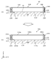
- FIG. 7 is a cross-sectional view showing the configuration of a power storage device 10a including power storage elements 100a according to Modification 2 of the present embodiment.
- FIG. 7 is a diagram corresponding to FIG.
- FIG. 8 is a diagram illustrating an example of the effects of power storage device 10a according to Modification 2 of the present embodiment.
- (a) of FIG. 8 is a cross-sectional view showing a configuration in which a cooling device 20 is arranged in the power storage device 10 in the above embodiment
- (b) of FIG. FIG. 3 is a cross-sectional view showing a configuration when a cooling device 20a is arranged in the power storage device 10a;
- a power storage device 10a in this modification includes a plurality of power storage elements 100a and a 1 and a tray 200a.
- Other configurations of this modified example are the same as those of the above-described embodiment, so detailed description thereof will be omitted.
- the power storage element 100a has a protrusion 114 that protrudes in the negative Z-axis direction (third direction) and is arranged between the pair of first bottom walls 230.
- the projecting portion 114 is a projection in the shape of a rectangular parallelepiped that extends in the X-axis direction and is flat in the Z-axis direction and protrudes in the negative Z-axis direction.
- the protrusion 114 has a shape corresponding to the opening 250a formed between the pair of first bottom walls 230 of the tray 200a.
- the container 110a of the power storage element 100a has a rectangular shape in which the short side surface 112a in the negative Z-axis direction is shorter in the X-axis direction than the short side surface 112 in the positive Z-axis direction.
- the direction end has a rectangular shape protruding in the negative direction of the Z axis.
- the protruding portion 114 protrudes in the negative Z-axis direction so that the tip end surface in the negative Z-axis direction is arranged at the same position in the Z-axis direction as the end surface of the pair of first bottom walls 230 in the negative Z-axis direction.
- the projecting portion 114 is inserted and fitted into the opening 250 a between the pair of first bottom walls 230 .
- the storage element 100a is restricted from moving in the X-axis direction.
- the power storage element 100a is provided with the projecting portion 114 arranged between the pair of first bottom walls 230 of the tray 200a, so that the power storage element 100a can be easily positioned with respect to the tray 200a. can be done.
- a configuration for weight reduction can be realized.
- the power storage device 10 in the above embodiment can be easily cooled.
- a cooling device 20 such as a water-cooled cooling plate or an air-cooled cooling plate using a heat sink
- a cooling device 20a such as a water-cooled cooling plate or an air-cooled cooling plate using a heat sink
- a plate-like cooling device is used.
- the device 20a may be brought into contact with the short side surface 112a of the storage element 100a.
- the cooling device 20a can be brought into contact with the short side surface 112a of the power storage element 100a without forming a protrusion in the cooling device 20a.
- the element 100a can be efficiently cooled.
- the protruding portion 114 of the power storage element 100a may be smaller than the opening 250a of the tray 200a, and the tip surface of the protruding portion 114 in the negative Z-axis direction is aligned with the Z-axis of the pair of first bottom walls 230. It does not have to be arranged at the same position in the Z-axis direction as the end face in the negative direction.
- tray 200 in the above embodiment may be arranged instead of tray 200a. good.
- the storage elements 100 and 100a (hereinafter referred to as the storage elements 100 and the like) have a pair of electrode terminals 120 projecting from both sides of the containers 110 and 110a (hereinafter referred to as the container 110 and the like) in the X-axis direction. It was assumed that However, a configuration in which a pair of electrode terminals 120 protrude from only one side of the container 110 or the like in the X-axis direction may be employed, or a configuration in which two electrode terminals 120 each protrude from both sides of the container 110 or the like in the X-axis direction may be employed.
- the electrode terminals 120 may protrude from the long side surfaces 111 and 111a (hereinafter referred to as the long side surfaces 111 and the like) or the short side surfaces 112 and 112a (hereinafter referred to as the short side surfaces 112 and the like) of the container 110 and the like.
- the arrangement position, projecting direction, number, etc. of the electrode terminals 120 are not particularly limited.
- both ends of the short side surfaces 112 and the like of the storage element 100 and the like are placed and fixed on the pair of first bottom walls 230 .
- the energy storage device 100 and the like may be fixed by placing both ends of the long side surfaces 111 and the like on the pair of first bottom walls 230 .
- all the power storage elements 100 and the like are placed and fixed on the pair of first bottom walls 230 .
- any storage element 100 or the like may not be fixed to any first bottom wall 230 .
- the power storage element 100 and the like are fixed to all of the pair of first side walls 210 and the pair of second side walls 220 .
- the storage device 100 and the like may not be fixed to any side wall or all of these side walls.
- the spacer 300 and the first adhesive 400 are arranged between every two adjacent power storage elements 100 .
- one or both of the spacer 300 and the first adhesive body 400 may not be arranged between any two storage elements 100 .
- the spacer 300 is an insulating double-sided tape having adhesive layers on both sides.
- the spacer 300 may be a hook-and-loop fastener structure called Velcro (registered trademark) or Velcro (registered trademark) tape or the like, which is detachably adhered.
- the spacer 300 may have an adhesive layer only on one side, or may be a resin spacer (holder) or the like that does not have an adhesive layer on both sides.
- the spacer 300 may be a conductive member having no insulation.
- the spacer 300 may have an uneven portion that forms a flow path or the like through which a coolant such as cooling air passes, on the surface facing the power storage element 100 .
- the first adhesive 400 is an insulating adhesive.
- the first adhesive 400 may be a non-insulating conductive adhesive, or may be an adhesive that does not have a so-called adhesive as long as it has a bonding function. Not limited.
- the fixing member 500 and the second adhesive body 600 may be a member such as a filler that does not have a bonding function.
- the present invention can be applied to a power storage device or the like having a power storage element such as a lithium ion secondary battery.
- Reference Signs List 10 10a power storage device 20, 20a cooling device 21, 114 protrusion 100, 100a power storage element 110, 110a container 111, 111a long side 112, 112a short side 113 terminal arrangement surface 120 electrode terminal 200, 200a tray 210 first side wall 220 Second side wall 230 First bottom wall 240 Second bottom wall 250, 250a Opening 300 Spacer 400 First adhesive 500 Fixing member 600 Second adhesive
Landscapes
- Engineering & Computer Science (AREA)
- Power Engineering (AREA)
- Chemical & Material Sciences (AREA)
- Chemical Kinetics & Catalysis (AREA)
- Electrochemistry (AREA)
- General Chemical & Material Sciences (AREA)
- Microelectronics & Electronic Packaging (AREA)
- Battery Mounting, Suspending (AREA)
Priority Applications (1)
| Application Number | Priority Date | Filing Date | Title |
|---|---|---|---|
| JP2022578425A JPWO2022163668A1 (https=) | 2021-01-29 | 2022-01-26 |
Applications Claiming Priority (2)
| Application Number | Priority Date | Filing Date | Title |
|---|---|---|---|
| JP2021012880 | 2021-01-29 | ||
| JP2021-012880 | 2021-01-29 |
Publications (1)
| Publication Number | Publication Date |
|---|---|
| WO2022163668A1 true WO2022163668A1 (ja) | 2022-08-04 |
Family
ID=82653566
Family Applications (1)
| Application Number | Title | Priority Date | Filing Date |
|---|---|---|---|
| PCT/JP2022/002746 Ceased WO2022163668A1 (ja) | 2021-01-29 | 2022-01-26 | 蓄電装置 |
Country Status (2)
| Country | Link |
|---|---|
| JP (1) | JPWO2022163668A1 (https=) |
| WO (1) | WO2022163668A1 (https=) |
Cited By (1)
| Publication number | Priority date | Publication date | Assignee | Title |
|---|---|---|---|---|
| JP2024126197A (ja) * | 2023-03-07 | 2024-09-20 | プライムプラネットエナジー&ソリューションズ株式会社 | 電池パックおよびその製造方法 |
Citations (2)
| Publication number | Priority date | Publication date | Assignee | Title |
|---|---|---|---|---|
| JP2008251471A (ja) * | 2007-03-30 | 2008-10-16 | Sanyo Electric Co Ltd | パック電池 |
| JP2015216071A (ja) * | 2014-05-13 | 2015-12-03 | 三菱自動車工業株式会社 | 電池パック |
Family Cites Families (1)
| Publication number | Priority date | Publication date | Assignee | Title |
|---|---|---|---|---|
| US12230820B2 (en) * | 2019-01-09 | 2025-02-18 | Byd Company Limited | Power battery pack and electric vehicle |
-
2022
- 2022-01-26 JP JP2022578425A patent/JPWO2022163668A1/ja active Pending
- 2022-01-26 WO PCT/JP2022/002746 patent/WO2022163668A1/ja not_active Ceased
Patent Citations (2)
| Publication number | Priority date | Publication date | Assignee | Title |
|---|---|---|---|---|
| JP2008251471A (ja) * | 2007-03-30 | 2008-10-16 | Sanyo Electric Co Ltd | パック電池 |
| JP2015216071A (ja) * | 2014-05-13 | 2015-12-03 | 三菱自動車工業株式会社 | 電池パック |
Cited By (2)
| Publication number | Priority date | Publication date | Assignee | Title |
|---|---|---|---|---|
| JP2024126197A (ja) * | 2023-03-07 | 2024-09-20 | プライムプラネットエナジー&ソリューションズ株式会社 | 電池パックおよびその製造方法 |
| JP7719113B2 (ja) | 2023-03-07 | 2025-08-05 | プライムプラネットエナジー&ソリューションズ株式会社 | 電池パックおよびその製造方法 |
Also Published As
| Publication number | Publication date |
|---|---|
| JPWO2022163668A1 (https=) | 2022-08-04 |
Similar Documents
| Publication | Publication Date | Title |
|---|---|---|
| JP7790356B2 (ja) | 蓄電装置 | |
| JP7484178B2 (ja) | 蓄電装置 | |
| WO2022255161A1 (ja) | 蓄電装置 | |
| JP7740024B2 (ja) | 蓄電装置 | |
| JP7392662B2 (ja) | 蓄電装置 | |
| JP7501370B2 (ja) | 蓄電装置 | |
| JP7286991B2 (ja) | 蓄電素子 | |
| WO2022163668A1 (ja) | 蓄電装置 | |
| JP7451915B2 (ja) | 蓄電素子 | |
| CN115298890A (zh) | 蓄电装置 | |
| WO2022255162A1 (ja) | 蓄電装置 | |
| JP7524551B2 (ja) | 蓄電装置 | |
| JP7427903B2 (ja) | 蓄電装置 | |
| JP2023149291A (ja) | 蓄電装置 | |
| JP2022143582A (ja) | 蓄電装置 | |
| US20260024862A1 (en) | Energy storage apparatus | |
| US20260005354A1 (en) | Energy storage apparatus | |
| JP2022029101A (ja) | 蓄電装置 | |
| US20240372197A1 (en) | Energy storage apparatus | |
| JP7786049B2 (ja) | 蓄電装置 | |
| JP2020107463A (ja) | 蓄電装置 | |
| EP4693667A1 (en) | Power storage device | |
| JP2020145118A (ja) | 蓄電素子 | |
| JP7552032B2 (ja) | 蓄電装置 | |
| WO2023171117A1 (ja) | 蓄電装置 |
Legal Events
| Date | Code | Title | Description |
|---|---|---|---|
| 121 | Ep: the epo has been informed by wipo that ep was designated in this application |
Ref document number: 22745888 Country of ref document: EP Kind code of ref document: A1 |
|
| ENP | Entry into the national phase |
Ref document number: 2022578425 Country of ref document: JP Kind code of ref document: A |
|
| NENP | Non-entry into the national phase |
Ref country code: DE |
|
| 122 | Ep: pct application non-entry in european phase |
Ref document number: 22745888 Country of ref document: EP Kind code of ref document: A1 |