WO2022162773A1 - 光アクセス網 - Google Patents
光アクセス網 Download PDFInfo
- Publication number
- WO2022162773A1 WO2022162773A1 PCT/JP2021/002780 JP2021002780W WO2022162773A1 WO 2022162773 A1 WO2022162773 A1 WO 2022162773A1 JP 2021002780 W JP2021002780 W JP 2021002780W WO 2022162773 A1 WO2022162773 A1 WO 2022162773A1
- Authority
- WO
- WIPO (PCT)
- Prior art keywords
- optical fiber
- fiber cable
- loop
- line
- core
- Prior art date
- Legal status (The legal status is an assumption and is not a legal conclusion. Google has not performed a legal analysis and makes no representation as to the accuracy of the status listed.)
- Ceased
Links
Images

Classifications
-
- H—ELECTRICITY
- H04—ELECTRIC COMMUNICATION TECHNIQUE
- H04B—TRANSMISSION
- H04B10/00—Transmission systems employing electromagnetic waves other than radio-waves, e.g. infrared, visible or ultraviolet light, or employing corpuscular radiation, e.g. quantum communication
- H04B10/27—Arrangements for networking
- H04B10/275—Ring-type networks
- H04B10/2755—Ring-type networks with a headend
-
- H—ELECTRICITY
- H04—ELECTRIC COMMUNICATION TECHNIQUE
- H04Q—SELECTING
- H04Q11/00—Selecting arrangements for multiplex systems
- H04Q11/0001—Selecting arrangements for multiplex systems using optical switching
- H04Q11/0005—Switch and router aspects
-
- H—ELECTRICITY
- H04—ELECTRIC COMMUNICATION TECHNIQUE
- H04B—TRANSMISSION
- H04B10/00—Transmission systems employing electromagnetic waves other than radio-waves, e.g. infrared, visible or ultraviolet light, or employing corpuscular radiation, e.g. quantum communication
- H04B10/03—Arrangements for fault recovery
-
- H—ELECTRICITY
- H04—ELECTRIC COMMUNICATION TECHNIQUE
- H04B—TRANSMISSION
- H04B10/00—Transmission systems employing electromagnetic waves other than radio-waves, e.g. infrared, visible or ultraviolet light, or employing corpuscular radiation, e.g. quantum communication
- H04B10/03—Arrangements for fault recovery
- H04B10/032—Arrangements for fault recovery using working and protection systems
-
- H—ELECTRICITY
- H04—ELECTRIC COMMUNICATION TECHNIQUE
- H04B—TRANSMISSION
- H04B10/00—Transmission systems employing electromagnetic waves other than radio-waves, e.g. infrared, visible or ultraviolet light, or employing corpuscular radiation, e.g. quantum communication
- H04B10/27—Arrangements for networking
-
- H—ELECTRICITY
- H04—ELECTRIC COMMUNICATION TECHNIQUE
- H04B—TRANSMISSION
- H04B10/00—Transmission systems employing electromagnetic waves other than radio-waves, e.g. infrared, visible or ultraviolet light, or employing corpuscular radiation, e.g. quantum communication
- H04B10/27—Arrangements for networking
- H04B10/271—Combination of different networks, e.g. star and ring configuration in the same network or two ring networks interconnected
-
- H—ELECTRICITY
- H04—ELECTRIC COMMUNICATION TECHNIQUE
- H04B—TRANSMISSION
- H04B10/00—Transmission systems employing electromagnetic waves other than radio-waves, e.g. infrared, visible or ultraviolet light, or employing corpuscular radiation, e.g. quantum communication
- H04B10/27—Arrangements for networking
- H04B10/275—Ring-type networks
-
- H—ELECTRICITY
- H04—ELECTRIC COMMUNICATION TECHNIQUE
- H04J—MULTIPLEX COMMUNICATION
- H04J14/00—Optical multiplex systems
- H04J14/02—Wavelength-division multiplex systems
- H04J14/0201—Add-and-drop multiplexing
-
- H—ELECTRICITY
- H04—ELECTRIC COMMUNICATION TECHNIQUE
- H04J—MULTIPLEX COMMUNICATION
- H04J14/00—Optical multiplex systems
- H04J14/02—Wavelength-division multiplex systems
- H04J14/0201—Add-and-drop multiplexing
- H04J14/0202—Arrangements therefor
- H04J14/021—Reconfigurable arrangements, e.g. reconfigurable optical add/drop multiplexers [ROADM] or tunable optical add/drop multiplexers [TOADM]
- H04J14/0212—Reconfigurable arrangements, e.g. reconfigurable optical add/drop multiplexers [ROADM] or tunable optical add/drop multiplexers [TOADM] using optical switches or wavelength selective switches [WSS]
-
- H—ELECTRICITY
- H04—ELECTRIC COMMUNICATION TECHNIQUE
- H04J—MULTIPLEX COMMUNICATION
- H04J14/00—Optical multiplex systems
- H04J14/02—Wavelength-division multiplex systems
- H04J14/0201—Add-and-drop multiplexing
- H04J14/0215—Architecture aspects
- H04J14/022—For interconnection of WDM optical networks
-
- H—ELECTRICITY
- H04—ELECTRIC COMMUNICATION TECHNIQUE
- H04J—MULTIPLEX COMMUNICATION
- H04J14/00—Optical multiplex systems
- H04J14/02—Wavelength-division multiplex systems
- H04J14/0278—WDM optical network architectures
- H04J14/0283—WDM ring architectures
-
- H—ELECTRICITY
- H04—ELECTRIC COMMUNICATION TECHNIQUE
- H04J—MULTIPLEX COMMUNICATION
- H04J14/00—Optical multiplex systems
- H04J14/02—Wavelength-division multiplex systems
- H04J14/0287—Protection in WDM systems
-
- H—ELECTRICITY
- H04—ELECTRIC COMMUNICATION TECHNIQUE
- H04Q—SELECTING
- H04Q11/00—Selecting arrangements for multiplex systems
- H04Q11/0001—Selecting arrangements for multiplex systems using optical switching
- H04Q11/0005—Switch and router aspects
- H04Q2011/0037—Operation
- H04Q2011/0041—Optical control
Definitions
- This disclosure relates to the technical field of designing an optical fiber cable network configuration in an access communication network.
- An optical access network is a communication facility network that connects telecommunication carrier base facilities (hereinafter referred to as “accommodation stations”) and multiple user bases with optical fiber cables, and requires high reliability in order to stably provide information and communication services. At the same time, it is required to efficiently meet the demand for optical fiber core wires scattered over the surface. Since the construction of an optical access network requires an enormous amount of equipment, time, and cost, it is important to design an appropriate network configuration in advance and build it in advance.
- the optical access network generally uses a network configuration based on a star-shaped wiring topology (see Non-Patent Document 1 for additional information).
- wiring sections are set in units of about several hundred users, and the accommodating stations and a plurality of wiring sections are connected with optical fiber cables in a tree-like manner.
- the required number of core wires calculated based on the demand forecast at the time of design is fixedly allocated, and the optical fiber cables are further arborized in the wiring section and connected to each user base.
- the star-shaped network configuration has two problems: it is difficult to ensure high reliability, and it is difficult to use core wires efficiently in response to fluctuations in demand.
- the present invention has been made in view of the above circumstances, and it is an object of the present invention to provide an optical access network that is highly reliable to support information communication services and that efficiently responds to unpredictable demand for fiber cores. do.
- the optical access network according to the present invention has a loop topology as a wiring topology, is composed of a plurality of looped optical fiber cables, and has a core switching function at the connection point between the loops.
- the optical access network is an upper loop optical fiber cable including a plurality of fixed office lines and at least one common line and laid in a looped path passing through telecommunications carrier base facilities; a lower loop optical fiber cable including at least one user line and at least one redundant line, laid in a looped path passing through a connection point with the upper loop optical fiber cable and the user base facility;
- An optical access network comprising a fixed connection line that connects the user line and the fixed office line in a 1:1 ratio at the connection point; and a core line switching function unit that exclusively connects the redundant line and the common line.
- the core line switching function unit is characterized by switching connection between the redundant line and the common line in accordance with fluctuations in demand for the lower loop optical fiber cable.
- this optical access network is composed of multiple looped optical fiber cables, it is possible to secure redundant routes and improve reliability. Furthermore, this optical access network can share core wires of some upper loop optical fiber cables with a plurality of lower loop optical fiber cables and switch connections according to demand, thereby efficiently meeting the demand. can be done.
- the present invention can provide an optical access network that has a high level of reliability that supports information communication services and that efficiently responds to core line demand that is difficult to predict.
- the optical access network according to the present invention preferably has the following conditions in order to reduce the frequency of construction work in response to demand fluctuations and to increase availability.
- the loop-shaped route of the upper loop optical fiber cable is a route from the communication carrier base facility to the connection point in the wiring section where the lower loop optical fiber cable is laid.
- the route is characterized by maximizing the availability improvement rate ⁇ when the upper loop optical fiber cable is used with respect to the availability when there is one.
- the improvement rate ⁇ is a number C1
- the loop-shaped route of the upper loop optical fiber cable is r loop that maximizes the improvement rate ⁇ .
- the shape of the area constructed by the upper loop optical fiber cable is a fan shape with a center angle ⁇ and a radius R with the telecommunications carrier base facility as the origin, and the r loop is from the telecommunications carrier base facility to the connection point is the demand density, C1 and C2 are constants.
- the number of core wires connecting the redundant line and the core switching function unit is a number that minimizes the number of core wires F total included in the upper loop optical fiber cable. It is characterized by
- the number of cores F total is calculated by the number C2.
- N is the number of the lower loop optical fiber cables connected to the upper loop optical fiber cable
- a i is the ratio of the number of the redundant lines among the core wires included in the i-th lower loop optical fiber cable ( hereinafter referred to as flexible fiber rate)
- f i is the core wire included in the i-th lower loop optical fiber cable
- Fc is the number of the common wires.
- x is the design value of the reliability per wiring section in which the lower loop optical fiber cable is laid
- p i,k is the probability that the number of demand generated in the i-th wiring section is k cores.
- q N,k is the probability that the sum of the number of demand exceeding the number of fixed station lines in the 1st to Nth wiring sections calculated by the number C5 is k cores.
- the present invention can provide an optical access network that has a high level of reliability that supports information communication services and that efficiently responds to core line demand that is difficult to predict.
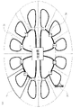
- FIG. 1 is a diagram illustrating the configuration of an optical access network according to the present invention
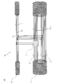
- FIG. FIG. 4 is a diagram for explaining fiber core connections at connection points that connect upper loops and lower loops of the optical access network according to the present invention
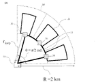
- FIG. 2 is a diagram explaining an example of an area model of an optical access network according to the present invention
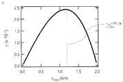
- FIG. 4 is a diagram illustrating the loop scale dependence of the availability improvement rate calculated in the optical access network according to the present invention
- FIG. 4 is a diagram for explaining dependence of the reliability per wiring section calculated in the optical access network according to the present invention on the number of lower loop cores
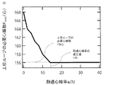
- FIG. 4 is a diagram for explaining the flexible core rate dependency of the required number of cores of upper loops calculated in the optical access network according to the present invention
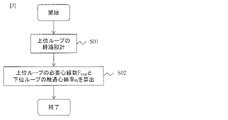
- FIG. 2 is a diagram explaining a design method for an optical access network according to the present invention
- FIG. 1 is a diagram for explaining the configuration of an optical access network according to this embodiment.
- FIG. 2 is a diagram for explaining fiber core connections at connection points that connect upper loops and lower loops of the optical access network of this embodiment.
- This optical access network is an upper loop optical fiber cable 11 including a plurality of fixed office lines 12 and at least one common line 13 and laid in a loop-shaped path passing through the communication carrier base facility 10;
- a lower loop optical fiber cable 21 including at least one user line 22 and at least one redundant line 23 and laid in a looped path passing through a connection point 30 with an upper loop optical fiber cable 11 and a user base facility 20
- An optical access network comprising At the connection point 30, a fixed connection line 32 that connects the user line 22 and the fixed office line 12 at 1:1, and a core line switching function unit 31 that exclusively connects the redundant line 23 and the common line 13 are provided.
- the core line switching function unit 31 is characterized by switching connection between the redundant line 23 and the common line 13 in accordance with fluctuations in demand for the lower loop optical fiber cable 21 .
- the wiring section 25 is an area where the lower loop optical fiber cable 21 is laid, and the user site 20 is installed.
- the communication carrier base facility 10 may be described as the "accommodating station 10".
- "Availability" is availability, and is a ratio obtained by dividing usable time (time excluding unusable time due to failure, construction, etc.) by total time.
- This optical access network configuration consists of optical fiber cables 11 (hereinafter referred to as upper loops) that connect wiring sections 25 and accommodation stations 10 in a loop, and optical fiber cables 21 (hereinafter referred to as loops) that are laid in each wiring section 25. a lower loop) and a fiber switching function unit 31 installed at a connection point 30 between the upper loop 11 and the lower loop 21 .
- the core switching function unit 31 is a wiring board or an optical switch that can be switched by connector connection.
- the wiring board or light switch may be remotely controllable.
- the wiring section 25 is designed to have a size that touches the upper loop 11 .
- the upper loop 11 is designed to have a size that maximizes the availability improvement rate ⁇ of the wiring section 25 connected thereto.
- the availability improvement rate ⁇ is obtained by the following equation, where ⁇ 1 is the availability when there is one route connecting the accommodation station 10 and the wiring section 25, and ⁇ 2 is the availability when there are two routes.
- ⁇ 1 and ⁇ 2 are obtained by the following equations.
- ⁇ is the failure rate indicating the number of failures per unit time
- ⁇ is the repair rate indicating the number of repairs per unit time.
- ⁇ and ⁇ are written as follows.
- a fan-shaped area having a center angle ⁇ and a radius R with the accommodating station 10 as the origin is assumed as the area shape for constructing the upper loop 11 and the wiring section 25 in contact with it.
- r loop is the distance from the accommodation station 10 to the far end of the upper loop 11
- ⁇ is the demand density (the number of core wires demanded per unit area)
- C1 and C2 are constants.
- equations (2) to (5) By substituting equations (2) to (5) into equation (1), the following equation is obtained as a derivation equation for the availability improvement rate.
- the size of the upper loop 11 is designed based on the condition of r loop that maximizes equation (6).
- the number of core wires required for the upper loop 11 (the total number of core wires included in the upper loop F total ) and the number of core wires connected to the core switching function unit 31 (the number of common wires 13 F c ) are determined as follows. .
- Number of core wires F total required to obtain a certain level of reliability (probability that expansion work is not required) in consideration of fluctuations in the number of demand generated in each wiring section 25 (the same as the above-mentioned “number of core wires demanded”) is obtained from the condition that minimizes
- the number of common lines Fc, the number of user lines 22 and the number of redundant lines 23 of the lower loop 21 are determined so that
- FIG. 2 is a core wire connection diagram at a connection point between the upper loop 11 and the lower loop 21.
- the core wires of the upper loop 11 are connected to the lower loop 21 via the core wire (fixed station line 12) directly connected to the lower loop 21 without being connected to the core switch function unit 31 and the core wire switching function unit 31.
- It is composed of a core wire (common line 13) that The common line 13 is shared by a plurality of lower loops 21 by connecting it to the core line switching function unit 31 of another lower loop 21, and is switched and connected by the core line switching function unit 31 so that it can be connected to any lower loop 21. Available.
- the required number of cores F total of the upper loop 11 is obtained by the following equation.
- N is the number of lower loops 21 connected to the upper loop 11
- a i is the number of core wires (redundant line 23) connected to the core switching function unit 31 among the required number of core wires f i of the i-th wiring section 25.
- flexible core rate f i is the number of required cores (the sum of the user line 22 and the redundant line 23) of the lower loop 21 in the i-th wiring section 25
- F c is the common line It is the number of thirteen.
- the i-th wiring section 25 accommodates the demand for a maximum of 2f i fibers with a cable with the number of cores f i . can. If x is the design value of the reliability per wiring section 25, it is necessary to design so that the probability that the number of demand generated in the i -th wiring section 25 is 2f i fibers or less is x or more. Design to satisfy the following formula. Note that x is described as "reliability per wiring section".
- p i,k is the probability that the number of demand generated in the i-th wiring section 25 is k cores.
- Fc must be designed so that the probability that the total number of demand exceeding that of the fixed station line 12 in the 1st to N -th wiring sections 25 is 2Fc cores or less is xN or more.
- q N,k is the probability that the total number of demand exceeding the number of fixed station lines 12 in the 1st to Nth wiring sections 25 is k cores, and is obtained by the following equation.
- the number of core wires connected to the core switching function unit 31 of the i-th wiring section 25 is designed so that the number of core wires on the upper loop 11 side is 2F c and the number of core wires on the lower loop 21 side is a i ⁇ 2f i . do.
- the flexible core rate ai at this time is designed so as to satisfy the condition that Ftotal is minimized in the ai dependency of Ftotal calculated from Equation (7).
- the upper loop 11 secures a redundant configuration on a different route between the accommodating station 10 and the wiring section 25, and also shares core line resources between the wiring sections 25.
- the lower loop 21 secures a redundant configuration in a different route between the connection point 30 with the upper loop 11 and the user site 20, and also shares the fiber core resources between the directions in the wiring section 25.
- the core line switching function unit 31 has the effect of reducing the required switching work operation when there is a demand imbalance between the wiring sections 25 connected to the upper loop 11 that differs from the prediction. Compared to the fusion splicing that is widely used in the conventional star network configuration, it is possible to reduce the construction operation time required for switching connection by preparing the core line switching function unit 31 using a wiring board or an optical switch in advance. If the wiring board or the optical switch can be remotely controlled, the on-site work itself can be reduced.
- Embodiments of the present invention will be described with reference to the accompanying drawings.
- the shape of the area is a sector with a center angle ⁇ of ⁇ /2 radians and a radius R of 2 km with the base station 10 as the origin.
- the three wiring sections 25 connected to the upper loop 11 have the same area.
- the present invention is not limited to this, and may be used under area conditions different from those of this embodiment.
- the size of the upper loop 11 is obtained from the r loop dependence of the availability improvement rate ⁇ calculated by Equation (6).
- FIG. 4 shows the calculation result of the r loop dependence of ⁇ .
- the upper loop 11 in this embodiment is designed so that the distance from the accommodation station 10 to the far end of the upper loop 11 is 1.2 km.
- the required number of cores f i of the lower loop 21 is designed so as to satisfy the condition of expression (8).
- r loop 1.2 km
- the area of each wiring section 25 connected to the upper loop 11 is 0.67 km 2
- the expected number of demand generated in each wiring section 25 is 67 fibers.
- FIG. 5 shows the calculation result of the dependence of the reliability x per wiring section 25 on the number of cores of the lower loop 21 in this embodiment.
- a normal distribution with an expected value of 67 cores and a standard deviation of ⁇ 67 cores is assumed as the probability density function of the number of demand generated per wiring section 25 .
- the required number of core wires for the lower loop 21 in this embodiment is 56 cores.
- the required number of cores F total and flexible fiber rate a i of the upper loop 11 are obtained from the flexible fiber rate dependency of F total calculated by the equation (7).
- FIG. 6 shows the calculation result of the flexibility fiber rate dependency of the required number of core wires of the upper loop 11 in this embodiment.
- calculation is performed with the same flexible core rate a for all wiring sections.
- F total converges to the minimum value of 156 fibers at a flexible fiber rate of 14% or more, so the required number of fibers for the upper loop 11 in this embodiment is 156 fibers.
- the flexible core wire rate is raised above 14%, the number of core wires required for the upper loop 11 does not change, and the number of connections of the core wire switching function unit 31 increases.
- the appropriate value of the flexible fiber ratio in this embodiment is 14%.
- the total number of core wires connected to the core switching function unit 31 (the connecting core wires 33 connected to the lower loop 11 and the clockwise and counterclockwise common wires 13 of the upper loop) is calculated as follows.
- the number of connecting cores on the upper loop side is not equal to the total number of cores connecting multiple lower loops and core switching function units, but is designed to be less than the total number.
- the total number is 48, but the number of connected core wires on the upper loop 11 side is more than that. 24 cores, which is also less.
- the 24 clockwise and counterclockwise 24 cores of the common line 13 of the upper loop 11 are shared by the 3 lower loops 21, and each lower loop 21 can use any 16 cores out of the 24 cores.
- the fiber switching function unit 31 treats the demand fluctuation of each of the lower loops 21 as the demand fluctuation of the three lower loops as a whole, so that the demand fluctuation can be handled with a smaller number of fiber cores than the total number. can produce.
- This optical access network can be designed as shown in FIG. (1)
- This optical access network is an upper loop optical fiber cable including a plurality of fixed office lines and at least one common line and laid in a looped path passing through telecommunications carrier base facilities; a lower loop optical fiber cable including at least one user line and at least one redundant line, laid in a looped path passing through a connection point with the upper loop optical fiber cable and the user base facility;
- An optical access network comprising a fixed connection line that connects the user line and the fixed office line in a 1:1 ratio at the connection point; and a core line switching function unit that exclusively connects the redundant line and the common line.
- the core line switching function unit is characterized by switching connection between the redundant line and the common line in accordance with fluctuations in demand for the lower loop optical fiber cable.
- This optical access network is designed by performing steps S01 and S02. (2) In step S01, Regarding the availability of the loop-shaped route of the upper loop optical fiber cable when there is only one route from the communication carrier base facility to the connection point in the wiring section where the lower loop optical fiber cable is laid Then, the path that maximizes the improvement rate ⁇ of availability when the upper loop optical fiber cable is used.
- the improvement rate ⁇ is a number C1
- the looped path of the upper loop optical fiber cable is r loop that maximizes the improvement rate ⁇ .
- the shape of the area constructed by the upper loop optical fiber cable is a fan shape with a center angle ⁇ and a radius R with the telecommunications carrier base facility as the origin, and the r loop is from the telecommunications carrier base facility to the connection point is the demand density, C1 and C2 are constants.
- step S02 The number of core wires connecting the redundant line and the core switching function unit is set to a number that minimizes the number of core wires F total included in the upper loop optical fiber cable.
- the number of cores F total is calculated by the number C2.
- N is the number of the lower loop optical fiber cables connected to the upper loop optical fiber cable
- a i is the ratio of the number of the redundant lines among the core wires included in the i-th lower loop optical fiber cable ( hereinafter referred to as flexible fiber rate)
- f i is the core wire included in the i-th lower loop optical fiber cable
- Fc is the number of the common wires.
- x is the design value of the reliability per wiring section in which the lower loop optical fiber cable is laid
- p i,k is the probability that the number of demand generated in the i-th wiring section is k cores.
- q N,k is the probability that the sum of the number of demand exceeding the number of fixed station lines in the 1st to Nth wiring sections calculated by the number C5 is k cores.
Landscapes
- Engineering & Computer Science (AREA)
- Computer Networks & Wireless Communication (AREA)
- Computing Systems (AREA)
- Physics & Mathematics (AREA)
- Electromagnetism (AREA)
- Signal Processing (AREA)
- Optical Communication System (AREA)
- Light Guides In General And Applications Therefor (AREA)
- Use Of Switch Circuits For Exchanges And Methods Of Control Of Multiplex Exchanges (AREA)
Priority Applications (3)
| Application Number | Priority Date | Filing Date | Title |
|---|---|---|---|
| JP2022577867A JP7540514B2 (ja) | 2021-01-27 | 2021-01-27 | 光アクセス網 |
| PCT/JP2021/002780 WO2022162773A1 (ja) | 2021-01-27 | 2021-01-27 | 光アクセス網 |
| US18/269,885 US12407416B2 (en) | 2021-01-27 | 2021-01-27 | Optical access network |
Applications Claiming Priority (1)
| Application Number | Priority Date | Filing Date | Title |
|---|---|---|---|
| PCT/JP2021/002780 WO2022162773A1 (ja) | 2021-01-27 | 2021-01-27 | 光アクセス網 |
Publications (1)
| Publication Number | Publication Date |
|---|---|
| WO2022162773A1 true WO2022162773A1 (ja) | 2022-08-04 |
Family
ID=82652766
Family Applications (1)
| Application Number | Title | Priority Date | Filing Date |
|---|---|---|---|
| PCT/JP2021/002780 Ceased WO2022162773A1 (ja) | 2021-01-27 | 2021-01-27 | 光アクセス網 |
Country Status (3)
| Country | Link |
|---|---|
| US (1) | US12407416B2 (cg-RX-API-DMAC7.html) |
| JP (1) | JP7540514B2 (cg-RX-API-DMAC7.html) |
| WO (1) | WO2022162773A1 (cg-RX-API-DMAC7.html) |
Citations (6)
| Publication number | Priority date | Publication date | Assignee | Title |
|---|---|---|---|---|
| JP2001313660A (ja) * | 2000-02-21 | 2001-11-09 | Nippon Telegr & Teleph Corp <Ntt> | 波長多重光ネットワーク |
| JP2002027512A (ja) * | 2000-07-10 | 2002-01-25 | Fujikura Ltd | 光回線切替方式 |
| JP2002057689A (ja) * | 2000-08-08 | 2002-02-22 | Nippon Telegr & Teleph Corp <Ntt> | 光伝達網及び光チャネル設定方法 |
| JP2002204511A (ja) * | 2000-10-25 | 2002-07-19 | Nippon Telegr & Teleph Corp <Ntt> | 通信媒体選定装置および方法と通信媒体選定プログラムを記録した記録媒体 |
| JP2003298517A (ja) * | 2002-04-02 | 2003-10-17 | Nippon Telegr & Teleph Corp <Ntt> | マルチレイヤ光ネットワーク |
| JP2005292447A (ja) * | 2004-03-31 | 2005-10-20 | Central Res Inst Of Electric Power Ind | アクティブ光クロージャおよびアクティブ光配線盤および光通信システム |
Family Cites Families (34)
| Publication number | Priority date | Publication date | Assignee | Title |
|---|---|---|---|---|
| SE9702688D0 (sv) * | 1997-07-11 | 1997-07-11 | Ericsson Telefon Ab L M | A method and system for interconnicting ring networks |
| US6295146B1 (en) * | 1998-01-14 | 2001-09-25 | Mci Communications Corporation | System and method for sharing a spare channel among two or more optical ring networks |
| US6616349B1 (en) * | 1999-12-20 | 2003-09-09 | Corning Incorporated | Two-fiber interconnected ring architecture |
| JP3703006B2 (ja) * | 2000-06-08 | 2005-10-05 | Kddi株式会社 | 放送型光ネットワークシステム |
| US6411412B1 (en) * | 2000-12-08 | 2002-06-25 | Seneca Networks | WDM optical communication network with data bridging plural optical channels between optical waveguides |
| JP2002271354A (ja) * | 2001-03-06 | 2002-09-20 | Fujitsu Ltd | 光路切替装置及び、これを用いる光波長多重ダイバシティ通信システム |
| WO2002075999A2 (en) * | 2001-03-16 | 2002-09-26 | Photuris, Inc. | Method and apparatus for interconnecting a plurality of optical transducers with a wavelength division multiplexed optical switch |
| KR100459572B1 (ko) * | 2002-10-15 | 2004-12-03 | 삼성전자주식회사 | 버스트 통신을 위한 다중 링형 광 네트워크 |
| US7356258B1 (en) * | 2002-11-26 | 2008-04-08 | Network Photonics, Inc. | Optical interconnection for traffic between a pair of DWDM rings |
| WO2004095779A1 (ja) * | 2003-04-24 | 2004-11-04 | Fujitsu Limited | リング間接続装置、及びデータ転送制御方法 |
| US20050019034A1 (en) * | 2003-07-25 | 2005-01-27 | Fujitsu Network Communications, Inc. | System and method for communicating optical traffic between ring networks |
| CN100508430C (zh) * | 2003-09-01 | 2009-07-01 | 烽火通信科技股份有限公司 | 光网络网间互通结构及其连接配置方法 |
| US20050196169A1 (en) * | 2004-03-03 | 2005-09-08 | Fujitsu Limited | System and method for communicating traffic between optical rings |
| JP4587792B2 (ja) * | 2004-11-30 | 2010-11-24 | 富士通株式会社 | リング状光伝送システムおよびこれに接続される光装置 |
| US7627245B2 (en) * | 2004-12-16 | 2009-12-01 | Tellabs Operations, Inc. | System and method for re-using wavelengths in an optical network |
| JP4593267B2 (ja) * | 2004-12-28 | 2010-12-08 | 富士通株式会社 | 光ノードおよび光分岐挿入装置 |
| US20060216029A1 (en) * | 2005-03-23 | 2006-09-28 | Fujitsu Limited | Method and system for improving upstream efficiency in extended broadcasting networks |
| US20060275035A1 (en) * | 2005-05-02 | 2006-12-07 | Way Winston I | Multiple interconnected broadcast and select optical ring networks with revertible protection switch |
| US7974533B2 (en) * | 2006-12-14 | 2011-07-05 | Verizon Patent And Licensing Inc. | Long reach optical network |
| JP4910893B2 (ja) * | 2007-06-07 | 2012-04-04 | 富士通株式会社 | タイムスロット入替装置 |
| KR100969741B1 (ko) * | 2008-07-11 | 2010-07-13 | 엘지노텔 주식회사 | 환형 혼성 성형망을 제공하기 위한 광통신 시스템 |
| US20100129076A1 (en) * | 2008-11-24 | 2010-05-27 | Giovanni Barbarossa | Method and apparatus for spectral band management |
| US8346089B2 (en) * | 2009-09-29 | 2013-01-01 | At&T Intellectual Property I, L.P. | Methods for expanding cross-connect capacity in a ROADM optical network |
| US8412042B2 (en) * | 2010-04-21 | 2013-04-02 | Cisco Technology, Inc. | Innovative architecture for fully non blocking service aggregation without O-E-O conversion in a DWDM multiring interconnection node |
| JP5617503B2 (ja) * | 2010-09-30 | 2014-11-05 | 富士通株式会社 | 光ネットワーク中継装置 |
| CN103797737B (zh) * | 2011-06-20 | 2017-02-15 | 普莱克希公司 | 使用用于数据中心网络交换的多光纤配置的光学架构和信道计划 |
| JP5397445B2 (ja) * | 2011-09-29 | 2014-01-22 | 沖電気工業株式会社 | 光中継装置 |
| EP2665212B1 (en) * | 2012-05-16 | 2016-11-30 | Alcatel Lucent | Optical data transmission system |
| US20140056565A1 (en) * | 2012-08-27 | 2014-02-27 | New Media Co., Ltd. | Optical fiber cable network and method of construction of an optical fiber cable network |
| WO2015066366A1 (en) * | 2013-10-30 | 2015-05-07 | Huawei Technologies Co., Ltd. | Network topology of hierarchical ring with gray code and binary code |
| CN105744385B (zh) * | 2014-12-10 | 2020-06-16 | 中兴通讯股份有限公司 | 一种光突发传送网的传输方法和系统 |
| EP3364568B1 (en) * | 2015-11-26 | 2020-04-15 | Nippon Telegraph and Telephone Corporation | Communication system and connector |
| US10931393B2 (en) * | 2018-06-11 | 2021-02-23 | Delta Electronics, Inc. | Intelligence-defined optical tunnel network system and network system control method |
| JP7529031B2 (ja) * | 2020-09-14 | 2024-08-06 | 日本電気株式会社 | 光ネットワーク、ネットワーク管理装置及びネットワーク管理方法 |
-
2021
- 2021-01-27 WO PCT/JP2021/002780 patent/WO2022162773A1/ja not_active Ceased
- 2021-01-27 US US18/269,885 patent/US12407416B2/en active Active
- 2021-01-27 JP JP2022577867A patent/JP7540514B2/ja active Active
Patent Citations (6)
| Publication number | Priority date | Publication date | Assignee | Title |
|---|---|---|---|---|
| JP2001313660A (ja) * | 2000-02-21 | 2001-11-09 | Nippon Telegr & Teleph Corp <Ntt> | 波長多重光ネットワーク |
| JP2002027512A (ja) * | 2000-07-10 | 2002-01-25 | Fujikura Ltd | 光回線切替方式 |
| JP2002057689A (ja) * | 2000-08-08 | 2002-02-22 | Nippon Telegr & Teleph Corp <Ntt> | 光伝達網及び光チャネル設定方法 |
| JP2002204511A (ja) * | 2000-10-25 | 2002-07-19 | Nippon Telegr & Teleph Corp <Ntt> | 通信媒体選定装置および方法と通信媒体選定プログラムを記録した記録媒体 |
| JP2003298517A (ja) * | 2002-04-02 | 2003-10-17 | Nippon Telegr & Teleph Corp <Ntt> | マルチレイヤ光ネットワーク |
| JP2005292447A (ja) * | 2004-03-31 | 2005-10-20 | Central Res Inst Of Electric Power Ind | アクティブ光クロージャおよびアクティブ光配線盤および光通信システム |
Also Published As
| Publication number | Publication date |
|---|---|
| JP7540514B2 (ja) | 2024-08-27 |
| US20240063911A1 (en) | 2024-02-22 |
| US12407416B2 (en) | 2025-09-02 |
| JPWO2022162773A1 (cg-RX-API-DMAC7.html) | 2022-08-04 |
Similar Documents
| Publication | Publication Date | Title |
|---|---|---|
| KR100901547B1 (ko) | 통신 메시들을 형성하기 위한 방법 및 장치 | |
| CN110740394B (zh) | 基于站点分级业务分类的电力光传输网络优化方法及系统 | |
| Savas et al. | Disaster-resilient control plane design and mapping in software-defined networks | |
| CN108809828A (zh) | 一种负载流量与业务风险联合均衡的电力通信网路由方法 | |
| CN110495143B (zh) | 提供冗余的分布式天线系统 | |
| Erbayat et al. | Fronthaul network architecture and design for optically powered passive optical networks | |
| Fujii et al. | Dynamic resource allocation with virtual grid for space division multiplexed elastic optical network | |
| US20140078888A1 (en) | Procedure, apparatus, system, and computer program for designing a virtual private network | |
| CN115361063A (zh) | 智慧光纤配线管理方法和系统 | |
| JP7540514B2 (ja) | 光アクセス網 | |
| Ambs et al. | Optimizing restoration capacity in the AT&T network | |
| TWI643478B (zh) | Sdn控制器及網路服務動態部署系統及方法 | |
| US20240259099A1 (en) | Optical access network and its design method | |
| JP7239932B2 (ja) | 網構築方法、網設計装置及び網設計プログラム | |
| JP7572653B2 (ja) | 予備機管理装置、予備機管理方法、及び、予備機管理プログラム | |
| JPWO2018074043A1 (ja) | 収容形態探索装置、収容形態探索方法及びプログラム | |
| JP2020123101A (ja) | クラスタリングシステムおよびクラスタリング方法 | |
| Anzola-Rojas et al. | Resilient planning for multi-access edge computing in sparsely populated areas | |
| Anzola-Rojas et al. | Improving joint planning of MEC and fiber deployment with duct and optical cable sharing | |
| JP5885293B2 (ja) | 加入者ユニット密度を考慮したネットワーク設備配置用のプログラム、装置及びシステム | |
| CN209929883U (zh) | 一种电源设备走线装置 | |
| Ferdousi et al. | Slice-aware service restoration with recovery trucks for optical metro-access networks | |
| Buysse et al. | On the impact of relocation on network dimensions in resilient optical Grids. | |
| Das et al. | Risk‐aware last‐minute data backup in inter‐datacenter networks | |
| WO2023095298A1 (ja) | 管理装置、管理方法、及び、管理プログラム |
Legal Events
| Date | Code | Title | Description |
|---|---|---|---|
| 121 | Ep: the epo has been informed by wipo that ep was designated in this application |
Ref document number: 21922797 Country of ref document: EP Kind code of ref document: A1 |
|
| ENP | Entry into the national phase |
Ref document number: 2022577867 Country of ref document: JP Kind code of ref document: A |
|
| WWE | Wipo information: entry into national phase |
Ref document number: 18269885 Country of ref document: US |
|
| NENP | Non-entry into the national phase |
Ref country code: DE |
|
| 122 | Ep: pct application non-entry in european phase |
Ref document number: 21922797 Country of ref document: EP Kind code of ref document: A1 |
|
| WWG | Wipo information: grant in national office |
Ref document number: 18269885 Country of ref document: US |