WO2022158171A1 - 基板洗浄装置、基板洗浄方法 - Google Patents
基板洗浄装置、基板洗浄方法 Download PDFInfo
- Publication number
- WO2022158171A1 WO2022158171A1 PCT/JP2021/045970 JP2021045970W WO2022158171A1 WO 2022158171 A1 WO2022158171 A1 WO 2022158171A1 JP 2021045970 W JP2021045970 W JP 2021045970W WO 2022158171 A1 WO2022158171 A1 WO 2022158171A1
- Authority
- WO
- WIPO (PCT)
- Prior art keywords
- substrate
- roll
- cleaning member
- roll cleaning
- motor
- Prior art date
- Legal status (The legal status is an assumption and is not a legal conclusion. Google has not performed a legal analysis and makes no representation as to the accuracy of the status listed.)
- Ceased
Links
Images




Classifications
-
- B—PERFORMING OPERATIONS; TRANSPORTING
- B08—CLEANING
- B08B—CLEANING IN GENERAL; PREVENTION OF FOULING IN GENERAL
- B08B1/00—Cleaning by methods involving the use of tools
- B08B1/20—Cleaning of moving articles, e.g. of moving webs or of objects on a conveyor
-
- B—PERFORMING OPERATIONS; TRANSPORTING
- B08—CLEANING
- B08B—CLEANING IN GENERAL; PREVENTION OF FOULING IN GENERAL
- B08B1/00—Cleaning by methods involving the use of tools
- B08B1/30—Cleaning by methods involving the use of tools by movement of cleaning members over a surface
- B08B1/32—Cleaning by methods involving the use of tools by movement of cleaning members over a surface using rotary cleaning members
-
- B—PERFORMING OPERATIONS; TRANSPORTING
- B08—CLEANING
- B08B—CLEANING IN GENERAL; PREVENTION OF FOULING IN GENERAL
- B08B1/00—Cleaning by methods involving the use of tools
- B08B1/30—Cleaning by methods involving the use of tools by movement of cleaning members over a surface
- B08B1/32—Cleaning by methods involving the use of tools by movement of cleaning members over a surface using rotary cleaning members
- B08B1/34—Cleaning by methods involving the use of tools by movement of cleaning members over a surface using rotary cleaning members rotating about an axis parallel to the surface
-
- B—PERFORMING OPERATIONS; TRANSPORTING
- B08—CLEANING
- B08B—CLEANING IN GENERAL; PREVENTION OF FOULING IN GENERAL
- B08B3/00—Cleaning by methods involving the use or presence of liquid or steam
- B08B3/02—Cleaning by the force of jets or sprays
-
- B—PERFORMING OPERATIONS; TRANSPORTING
- B08—CLEANING
- B08B—CLEANING IN GENERAL; PREVENTION OF FOULING IN GENERAL
- B08B3/00—Cleaning by methods involving the use or presence of liquid or steam
- B08B3/04—Cleaning involving contact with liquid
- B08B3/041—Cleaning travelling work
-
- H—ELECTRICITY
- H10—SEMICONDUCTOR DEVICES; ELECTRIC SOLID-STATE DEVICES NOT OTHERWISE PROVIDED FOR
- H10P—GENERIC PROCESSES OR APPARATUS FOR THE MANUFACTURE OR TREATMENT OF DEVICES COVERED BY CLASS H10
- H10P52/00—Grinding, lapping or polishing of wafers, substrates or parts of devices
-
- H—ELECTRICITY
- H10—SEMICONDUCTOR DEVICES; ELECTRIC SOLID-STATE DEVICES NOT OTHERWISE PROVIDED FOR
- H10P—GENERIC PROCESSES OR APPARATUS FOR THE MANUFACTURE OR TREATMENT OF DEVICES COVERED BY CLASS H10
- H10P72/00—Handling or holding of wafers, substrates or devices during manufacture or treatment thereof
- H10P72/04—Apparatus for manufacture or treatment
- H10P72/0402—Apparatus for fluid treatment
- H10P72/0406—Apparatus for fluid treatment for cleaning followed by drying, rinsing, stripping, blasting or the like
- H10P72/0411—Apparatus for fluid treatment for cleaning followed by drying, rinsing, stripping, blasting or the like for wet cleaning or washing
- H10P72/0412—Apparatus for fluid treatment for cleaning followed by drying, rinsing, stripping, blasting or the like for wet cleaning or washing using mainly scrubbing means, e.g. brushes
Definitions
- the present disclosure relates to a substrate cleaning apparatus and a substrate cleaning method.
- This apparatus includes a substrate rotation support that holds and rotates a semiconductor substrate to be cleaned, a roll sponge that rotates around an axis parallel to the surface of the substrate, and a cleaning liquid that supplies the cleaning liquid to the surface of the substrate to be cleaned. have a nozzle.
- the substrate rotation support part rotates while supporting the outer periphery of the substrate, and the rotational force thereof is transmitted to the outer surface of the substrate to rotate the substrate.
- the roll sponge rotates around its central axis and cleans the surface of the substrate while rubbing it.
- the length of the roll cleaning member is the length that spans the diameter of the substrate.
- the sliding directions of the sliding contact portions between the roll cleaning member and the substrate are the same in one radial region on the axis of the roll cleaning member.
- the rotating roll cleaning member receives particles on the substrate and acts to entwine them into the substrate, so it hardly contributes to the cleaning of the substrate, and on the contrary, roll cleaning This has the effect of redepositing particles from the component onto the substrate.
- Japanese Patent Application Laid-Open No. 2002-313767 discloses that the length of the roll cleaning member extending in the direction parallel to the substrate is the length covering the radius of the substrate, and the sliding directions of the sliding contact portions between the roll cleaning member and the substrate are opposite to each other. It is disclosed that However, the required specifications for cleaning performance are increasing year by year, and further improvement is required.
- a substrate cleaning apparatus includes a substrate rotation support that supports and rotates the substrate; a roll cleaning member holding portion rotatably holding a first roll cleaning member and a second roll cleaning member having a length substantially equal to the radius of the substrate; a roll rotation driving unit that rotates the first roll cleaning member and the second roll cleaning member around respective center axes parallel to the surface of the substrate; a roll pressing portion that causes the rotating first roll cleaning member and the second roll cleaning member to come into sliding contact with the surface of the substrate; with The first roll cleaning member and the second roll cleaning member are arranged to cover different radius portions of the surface of the substrate.
- a substrate processing method comprises arranging a first roll cleaning member and a second roll cleaning member having lengths approximately equal to the radius of the substrate to cover different radius portions of the surface of the substrate; While rotating the substrate, the first roll cleaning member and the second roll cleaning member are brought into sliding contact with the surface of the substrate while rotating around their respective center axes parallel to the surface of the substrate.
- FIG. 1 is a plan view showing the overall configuration of a substrate processing apparatus according to one embodiment.
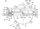
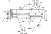
- FIG. 2 is a plan view showing a schematic configuration of the substrate cleaning apparatus according to one embodiment.
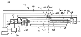
- FIG. 3 is a side view of the substrate cleaning apparatus according to the embodiment when viewed from the front direction in FIG.
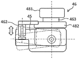
- FIG. 4 is a side view of the substrate cleaning apparatus according to the embodiment when viewed from the right side in FIG.
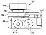
- FIG. 5 is a cross-sectional view of the substrate cleaning apparatus according to one embodiment taken along line AA shown in FIG.
- FIG. 6 is a cross-sectional view of the substrate cleaning apparatus according to one embodiment taken along the line BB shown in FIG.
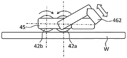
- FIG. 7 is a diagram for explaining the operation of the second pressing section.
- FIG. 1 is a plan view showing the overall configuration of a substrate processing apparatus according to one embodiment.
- FIG. 2 is a plan view showing a schematic configuration of the substrate cleaning apparatus according to one embodiment.
- FIG. 3 is a side view of the substrate cleaning apparatus according
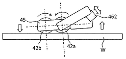
- FIG. 8 is a diagram for explaining the operation of the second pressing section.
- FIG. 9 is a diagram for explaining the operation of the roll translation unit.
- FIG. 10 is an enlarged view showing the configuration of the power transmission section of the roll rotation drive section.
- 11 is a diagram for explaining the operation of the power transmission unit shown in FIG. 10.
- FIG. 12 is a plan view showing the overall configuration of a substrate processing apparatus according to one modification of one embodiment.
- a substrate cleaning apparatus includes: a substrate rotation support that supports and rotates the substrate; a roll cleaning member holding portion rotatably holding a first roll cleaning member and a second roll cleaning member having a length substantially equal to the radius of the substrate; a roll rotation driving unit that rotates the first roll cleaning member and the second roll cleaning member around respective center axes parallel to the surface of the substrate; a roll pressing portion that causes the rotating first roll cleaning member and the second roll cleaning member to come into sliding contact with the surface of the substrate; with The first roll cleaning member and the second roll cleaning member are arranged to cover different radius portions of the surface of the substrate.
- the first roll cleaning member and the second roll cleaning member are brought into sliding contact with the surface of the substrate.
- the surface of the substrate is cleaned twice by the first roll cleaning member and the second roll cleaning member during one rotation, so that the particle removal capability can be doubled.
- a substrate cleaning apparatus is the substrate cleaning apparatus according to the first aspect, In the roll rotation driving portion, sliding directions in the sliding contact portion between the first roll cleaning member and the substrate are opposite to each other, and sliding in the sliding contact portion between the second roll cleaning member and the substrate is performed. The first roll cleaning member and the second roll cleaning member are rotated in opposite directions.
- the first roll cleaning member and the second roll cleaning member are applied to the cleaning member when cleaning the substrate while bringing the rotating substrate and the cleaning member rotating around the axis into contact with each other. Since it rotates so as to meet particles on the substrate that are relatively approaching and scrape them up, the ability to remove particles can be improved.
- a substrate cleaning apparatus is the substrate cleaning apparatus according to the first or second aspect,
- the central axis of the first roll cleaning member and the central axis of the second roll cleaning member are parallel to each other, and the first roll cleaning member and the second roll cleaning member are arranged so as to clean the surface of the substrate. They are arranged so as to cover radial portions on opposite sides of the substrate with the center of the substrate therebetween.
- the first roll cleaning member and the second roll cleaning member can be easily held by the same roll rotation holding portion, and the device configuration can be simplified.
- a substrate cleaning apparatus is the substrate cleaning apparatus according to any one of the first to third aspects,
- the roll rotation drive section rotates the first roll cleaning member and the second roll cleaning member at different rotation speeds.
- the relative speed at the sliding contact portion between the first roll cleaning member and the substrate can be made different from the relative speed at the sliding contact portion between the second roll cleaning member and the substrate.
- a substrate cleaning apparatus is the substrate cleaning apparatus according to any one of the first to fourth aspects,
- the roll rotation drive unit has a motor for rotating the first roll cleaning member and the second roll cleaning member,
- the substrate cleaning apparatus has a control device that controls the roll pressing section, The control device receives a signal of the load torque of the motor and, when the load torque of the motor exceeds a preset upper limit value, responds to the difference between the upper limit value and the load torque of the motor.
- the first roll cleaning member and the second roll cleaning member are separated from the substrate by a distance, and when the load torque of the motor falls below a preset lower limit value, the lower limit value and the motor
- the roll pressing section is controlled so that the first roll cleaning member and the second roll cleaning member are brought closer to the substrate by a distance corresponding to the difference from the load torque of .
- the state of pressing of the roll cleaning member against the substrate surface can be kept within a certain range, and stable cleaning performance can be achieved. can be maintained.
- a substrate cleaning apparatus is the substrate cleaning apparatus according to any one of the first to fifth aspects,
- the roll pressing part is By applying a load in a direction perpendicular to the surface of the substrate to the roll cleaning member holding portion, the first roll cleaning member and the second roll cleaning member are brought into sliding contact with the surface of the substrate.
- the size of the particles can be reduced by performing scrub cleaning using the first roll cleaning member and the second roll cleaning member after providing a difference in the pressing load of the plurality of roll cleaning members against the substrate. Since it is possible to realize a suitable removing action and immediately remove particles reattached to the substrate from the roll cleaning member, it is possible to improve the ability to remove particles.
- a substrate cleaning apparatus is the substrate cleaning apparatus according to any one of the first to sixth aspects,
- the roll rotation drive section has a first motor that rotates the first roll cleaning member and a second motor that rotates the second roll cleaning member.
- a substrate cleaning apparatus is the substrate cleaning apparatus according to the seventh aspect,
- the first The first roll cleaning member is separated from the substrate by a distance corresponding to the difference between the upper limit value and the load torque of the first motor, and the load torque of the first motor is the preset first is less than the lower limit, the first roll cleaning member is brought close to the substrate by a distance corresponding to the difference between the first lower limit and the load torque of the first motor,
- the second motor is moved by a distance corresponding to the difference between the second upper limit value and the load torque of the second motor.
- the state of pressing of the roll cleaning member against the substrate surface can be kept within a certain range, and stable cleaning performance can be achieved. can be maintained.
- a substrate cleaning apparatus is the substrate cleaning apparatus according to any one of the first to sixth aspects,
- the roll rotation drive section has a first motor that rotates the first roll cleaning member, and a power transmission section that transmits the rotation of the first roll cleaning member to the second roll cleaning member.
- power can be transmitted to the two roll cleaning members without installing two motors, so space can be saved, and the weight of the apparatus can be reduced.
- a substrate cleaning apparatus is the substrate cleaning apparatus according to any one of the first to ninth aspects, It further comprises a roll translation unit that moves the first roll cleaning member and the second roll cleaning member integrally in a direction parallel to the surface of the substrate.
- the roll cleaning member can be reciprocated in a direction orthogonal to the central axis of the roll cleaning member.
- the roll cleaning member can be brought into sliding contact with the central portion of the substrate, and the central portion of the substrate can be evenly cleaned.
- cleaning is performed only in an arrangement in which the central axis of the roll cleaning member overlaps the diameter of the substrate in a plan view. The position is a fixed position at a radial distance from the center of the substrate, and the number of contacts of the nodules is unevenly distributed depending on the radial position.
- the time until the end of cleaning is determined at a position where the number of times of nodule contact is small.
- cleaning is performed while reciprocating the roll cleaning member in a direction orthogonal to the central axis of the roll cleaning member, so that the surface of the roll cleaning member provided on the outer periphery of the surface of the roll cleaning member is cleaned.
- the position of the nodule becomes a variable position depending on the radial distance from the center of the substrate, and uneven distribution of the number of contact of the nodule due to the radial position is suppressed, and the time until the end of cleaning can be relatively shortened.
- a substrate cleaning apparatus is the substrate cleaning apparatus according to any one of the first to tenth aspects, A cleaning liquid nozzle for supplying a cleaning liquid to the surface of the substrate is further provided.
- a substrate cleaning apparatus is the substrate cleaning apparatus according to the eleventh aspect,
- the cleaning liquid nozzles supply a cleaning liquid to a sliding contact portion between the first roll cleaning member and the substrate, and a cleaning liquid to a sliding contact portion between the second roll cleaning member and the substrate. and a second cleaning liquid nozzle for cleaning.
- the cleaning liquid can be efficiently supplied to the sliding contact portion between each roll cleaning member and the substrate.
- a substrate cleaning apparatus is the substrate cleaning apparatus according to the twelfth aspect, the first cleaning liquid nozzle supplies a cleaning liquid from an upstream side in a rotation direction of the substrate to a sliding contact portion between the first roll cleaning member and the substrate; The second cleaning liquid nozzle supplies the cleaning liquid from the upstream side in the rotation direction of the substrate to the sliding contact portion between the second roll cleaning member and the substrate.
- the cleaning liquid can be more efficiently supplied to the sliding contact portion between each roll cleaning member and the substrate.
- a substrate cleaning apparatus is the substrate cleaning apparatus according to any one of the eleventh to thirteenth aspects,
- the cleaning liquid nozzle has a third cleaning liquid nozzle that supplies cleaning liquid to the central portion of the substrate.
- the cleaning liquid can be efficiently supplied to the central portion of the substrate.
- a substrate processing apparatus includes a substrate polishing apparatus for polishing a substrate; a substrate cleaning apparatus according to any one of aspects 1 to 14, which cleans the substrate after polishing; Prepare.
- a substrate processing method comprises arranging a first roll cleaning member and a second roll cleaning member having lengths approximately equal to the radius of the substrate to cover different radius portions of the surface of the substrate; While rotating the substrate, the first roll cleaning member and the second roll cleaning member are brought into sliding contact with the surface of the substrate while rotating around their respective center axes parallel to the surface of the substrate.
- FIG. 1 is a plan view showing the overall configuration of a substrate processing apparatus 1 equipped with a substrate cleaning apparatus according to one embodiment.
- the substrate processing apparatus 1 has a substantially rectangular housing 10 and a load port 12 on which a substrate cassette (not shown) for stocking a plurality of substrates W is mounted. .
- a load port 12 is positioned adjacent to the housing 10 .
- the load port 12 can be loaded with an open cassette, a SMIF (Standard Manufacturing Interface) pod, or a FOUP (Front Opening Unified Pod).
- SMIF pods and FOUPs are closed containers that contain substrate cassettes and are covered with partition walls to maintain an environment independent of the external space.
- the substrate W may be, for example, a semiconductor wafer.
- substrates to be processed are not limited to semiconductor wafers, and may be other types of substrates used in the manufacture of semiconductor devices, such as glass substrates and ceramic substrates.
- polishing units 14a to 14d for polishing the substrate W
- first cleaning unit 16 for cleaning the substrate W after polishing
- second cleaning unit 18 and a drying unit 20 for drying the substrate W after cleaning are accommodated.
- the polishing units 14 a - 14 d are arranged along the longitudinal direction of the housing 10
- the cleaning units 16 , 18 and the drying unit 20 are also arranged along the longitudinal direction of the housing 10 .
- the target is a substrate W having no trenches on the substrate surface.
- the substrate W whose surface is wet after being subjected to the chemical mechanical polishing process, which is a wet process, is transported to the first cleaning unit 16 as it is without drying the surface.
- the substrate W cleaned by the first cleaning unit 16 is transferred to the second cleaning unit 18 without being dried, and the substrate W cleaned by the second cleaning unit 18 is transferred to the drying unit 20 without being dried. , and the substrate W is dried in the drying unit 20 for the first time.
- a first transfer robot 22 is arranged in an area surrounded by the load port 12 , the polishing unit 14 a located on the load port 12 side, and the drying unit 20 . Between the area where the polishing units 14a to 14d are arranged and the area where the cleaning units 16 and 18 and the drying unit 20 are arranged, a transport unit 24 is arranged parallel to the longitudinal direction of the housing 10. there is The first transport robot 22 receives the substrate W before polishing from the load port 12 and transfers it to the transport unit 24 , or receives the substrate W after drying taken out from the drying unit 20 from the transport unit 24 .
- a second transport robot 26 for transferring the substrate W between the first cleaning unit 16 and the second cleaning unit 18 is arranged between the first cleaning unit 16 and the second cleaning unit 18 .
- a third transfer robot 28 is arranged between the second cleaning unit 18 and the drying unit 20 to transfer the substrate W between the second cleaning unit 18 and the drying unit 20 .
- the substrate processing apparatus 1 is provided with a control device 30 that controls the movements of the devices 14a to 14d, 16, 18, 20, 22, 24, 26, and .
- a programmable logic controller (PLC) for example, is used as the control device 30 .
- PLC programmable logic controller
- the control device 30 is arranged inside the housing 10 in the embodiment shown in FIG. 1 , the control device 30 may be arranged outside the housing 10 without being limited thereto.
- a horizontally extending roll cleaning member is brought into contact with the surface of the substrate W in the presence of cleaning liquid, and the surface of the substrate W is scrub-cleaned while rotating the roll cleaning member.
- a columnar pencil cleaning member extending in the vertical direction is brought into contact with the surface of the substrate W in the presence of cleaning liquid, and the substrate is cleaned while rotating the pencil cleaning member.
- a pencil cleaning device is used that scrubs and cleans the surface of the substrate W by moving it in one direction parallel to the surface of the substrate W.
- the drying unit 20 dries the substrate W by ejecting isopropyl alcohol (IPA) vapor from an ejection nozzle that moves in one direction parallel to the surface of the substrate W toward the rotating substrate W, and further dries the substrate W.
- IPA isopropyl alcohol
- a spin drying apparatus is used that spins the substrate W at high speed and dries it by centrifugal force.
- a roll cleaning device is used as the first cleaning unit 16, but a pencil cleaning device similar to the second cleaning unit 18 may be used as the first cleaning unit 16, or the presence of cleaning liquid may be used.
- a buff cleaning and polishing member having a rotation axis extending in the vertical direction is brought into contact with the surface of the substrate W, and the buff cleaning and polishing member is moved in one direction parallel to the surface of the substrate W while rotating on its axis.
- a buffing cleaning device that scrubs and polishes the surface of the substrate W may be used, or a two-fluid jet cleaning device that cleans the surface of the substrate W with a two-fluid jet may be used.
- a pencil cleaning device is used as the second cleaning unit 18, but a roll cleaning device similar to the first cleaning unit 16 may be used as the second cleaning unit 18, or a buffing cleaning device may be used.
- a device may be used, or a two-fluid jet cleaning device may be used.
- the cleaning liquid includes a rinse liquid such as pure water (DIW), an ammonia-hydrogen peroxide solution mixture (SC1), a hydrochloric acid-hydrogen peroxide solution mixture (SC2), a sulfuric acid-hydrogen peroxide solution (SPM), a sulfuric acid solution, and a hydrofluoric acid solution. and other chemical solutions.
- a rinse liquid such as pure water (DIW), an ammonia-hydrogen peroxide solution mixture (SC1), a hydrochloric acid-hydrogen peroxide solution mixture (SC2), a sulfuric acid-hydrogen peroxide solution (SPM), a sulfuric acid solution, and a hydrofluoric acid solution. and other chemical solutions.
- DIW pure water
- SC1 ammonia-hydrogen peroxide solution mixture
- SC2 hydrochloric acid-hydrogen peroxide solution mixture
- SPM sulfuric acid-hydrogen peroxide solution
- sulfuric acid solution sulfuric acid solution
- hydrofluoric acid solution Unless otherwise specified in this
- FIG. A substrate cleaning apparatus 40 according to one embodiment will be described with reference to FIGS. 2 to 4.
- FIG. A substrate cleaning apparatus 40 according to one embodiment can be applied to both the first cleaning unit 16 and the second cleaning unit 18 .
- FIG. 2 is a plan view showing a schematic configuration of a substrate cleaning apparatus 40 according to one embodiment.
- FIG. 3 is a side view of the substrate cleaning apparatus 40 according to one embodiment when viewed from the front direction in FIG.
- FIG. 4 is a side view of the substrate cleaning apparatus 40 according to one embodiment when viewed from the right side in FIG.
- the substrate cleaning apparatus 40 includes a substrate rotation support section 41 that supports and rotates the substrate W, a first roll cleaning member 42a having a length substantially equal to the radius of the substrate W, and a A roll holding portion 45 that rotatably holds the second roll cleaning member 42b, a roll rotation driving portion 43 that rotates the first roll cleaning member 42a and the second roll cleaning member 42b, and the first roll cleaning member.
- 42a and the second roll cleaning member 42b are pressed against the surface of the substrate W, and roll translation movement moves the first roll cleaning member 42a and the second roll cleaning member 42b parallel to the surface of the substrate W.
- a cleaning liquid nozzle 44 for supplying cleaning liquid to the surface of the substrate W.
- the substrate rotation support part 41 for example, a plurality of (four in the illustrated example) spin chucks that rotate while supporting the outer periphery of the substrate W are used.
- the substrate W is held by the substrate rotation support portion 41 with its surface facing up.
- the rotational force of the substrate rotation support part 41 is transmitted to the outer surface of the substrate W, and the substrate W moves along the surface of the substrate W through its central axis (center O). ) is the axis of rotation.
- the first roll cleaning member 42a and the second roll cleaning member 42b are, for example, cylindrical roll sponges made of PVA (polyvinyl alcohol). As shown in FIGS. 2 and 3, rotating shafts 42a1 and 42b1 extend coaxially with the central axes of the first roll cleaning member 42a and the second roll cleaning member 42b from both ends in the axial direction. , and both ends of the rotary shafts 42 a 1 and 42 b 1 are rotatably held by roll holding portions 45 . In the illustrated example, the first roll cleaning member 42a and the second roll cleaning member 42b are held by the same roll holding portion 45, but the present invention is not limited to this. The roll cleaning member 42a and the second roll cleaning member 42b may be held by different roll holding portions.
- PVA polyvinyl alcohol
- the first roll cleaning member 42a and the second roll cleaning member 42b each have a length approximately equal to the radius of the substrate W.
- the first roll cleaning member 42a and the second roll cleaning member 42b cover different radius portions of the surface of the substrate W with their central axes oriented parallel to the surface of the substrate W. configured to be arranged to
- the center axis of the first roll cleaning member 42a and the center axis of the second roll cleaning member 42b are parallel to each other, and the first roll cleaning member 42a and the second roll cleaning member 42b are , are arranged to cover opposite radial portions of the surface of the substrate W.
- the first roll cleaning member 42a and the second roll cleaning member 42b are parallel to each other, the first roll cleaning member 42a and the second roll cleaning member 42b can be attached to the same roll holding portion. 45 can be easily held, and the configuration of the device becomes simpler than a configuration in which different roll holding portions are held.
- the roll rotation drive unit 43 rotates the first roll cleaning member 42a and the second roll cleaning member 42b around their central axes parallel to the surface of the substrate W.
- the roll rotation driving section 43 may rotate the first roll cleaning member 42a and the second roll cleaning member 42b at different rotation speeds.
- the roll rotation driving section 43 includes a first motor 431 that rotates the first roll cleaning member 42a and a second roll cleaning member that rotates the first roll cleaning member 42a. 42b.
- the first motor 431 is connected to one end of the rotating shaft 42a1 of the first roll cleaning member 42a, and directly transmits the rotating force to the rotating shaft 42a1 of the first roll cleaning member 42a.
- the first roll cleaning member 42a is rotated around its central axis.
- FIG. 10 is an enlarged view showing the configuration of the power transmission section 432.
- FIG. 11 is a view of the power transmission unit 432 viewed from the right side in FIG. 10, and is a diagram for explaining the operation of the power transmission unit 432.
- FIG. 11 is a view of the power transmission unit 432 viewed from the right side in FIG. 10, and is a diagram for explaining the operation of the power transmission unit 432.
- the power transmission unit 432 includes first to third pulleys 41 to 53, a belt 50 stretched over the first to third pulleys 51 to 53, the first and It has second gears 54 , 55 .
- the first pulley 51 is provided coaxially with the rotating shaft 42a1 of the first roll cleaning member 42a, and is rotatable integrally with the first roll cleaning member 42a.
- the belt 50 is stretched over first to third pulleys 51-53.
- the first gear 54 is provided coaxially with the second pulley 52 and is rotatable together with the second pulley 52 .
- the second gear 55 is provided coaxially with the rotating shaft 42a1 of the second roll cleaning member 42a, and is rotatable integrally with the second roll cleaning member 42a. Also, the second gear 55 meshes with the first gear 54 .
- the roll rotation drive unit 43 has the first motor 431 and the power transmission unit 432, power can be transmitted to the two roll cleaning members 42a and 42b without installing two motors. , for example, the space can be saved, and the weight of the device can be reduced.
- the second pulley 52 is a variable speed pulley.
- the width of the V-groove of the second pulley 52 is movable, and when no load is applied, the width of the V-groove is narrowed by a spring force or the like, resulting in a substantially large diameter (the second pulley 52 and the belt 60 shown by broken lines in FIG. 11). shape).
- the third pulley 53 is a position-movable tensional pulley. When the third pulley 53 is displaced upward in FIG. 11, the belt 60 overcomes the spring force of the second pulley 52 and widens the width of the V groove, reducing the pulley diameter (solid line in FIG. 11). (see shape of second pulley 52 and belt 60 indicated by ).
- the reduction in the diameter of the second pulley 52 increases the number of rotations of the second pulley 52 and the first gear 54, thereby increasing the number of rotations of the second gear 55 and the second roll cleaning member 42b. increases (rotation speed increases). Therefore, the rotation speed of the first roll cleaning member 42a and the rotation speed of the second roll cleaning member 42b can be made different from each other.
- the roll rotation drive unit 43 includes a first motor 431 that rotates the first roll cleaning member 42a and a second motor 431b that rotates the second roll cleaning member 42b. and
- the first motor 431 is connected to one end of the rotating shaft 42a1 of the first roll cleaning member 42a, and directly transmits the rotational force to the rotating shaft 42a1 of the first roll cleaning member 42a to perform the first cleaning.
- the roll cleaning member 42a is rotated around its central axis.
- the second motor 431b is connected to one end of the rotating shaft 42b1 of the second roll cleaning member 42b, and directly transmits the rotational force to the rotating shaft 42b1 of the second roll cleaning member 42b.
- the second roll cleaning member 42b is rotated around its central axis. With such a configuration as well, it is possible to make the number of revolutions of the first roll cleaning member 42a and the number of revolutions of the second roll cleaning member 42b different from each other.
- the roll pressing part 46 brings the rotating first roll cleaning member 42a and the second roll cleaning member 42b into sliding contact with the surface of the substrate W.
- the roll pressing section 46 has a first pressing section 461 and a second pressing section 462.
- the first pressing part 461 applies a load in a direction perpendicular to the surface of the substrate W to the roll holding part 45 , thereby pressing the first roll cleaning member 42 a and the second roll cleaning member 42 b onto the surface of the substrate W. slide on.
- the first pressing portion 461 is an actuator and is connected to the base end portion of the horizontally extending first arm portion 481 .
- a second arm portion 482 is supported so as to be suspended from the tip portion of the first arm portion 481 , and the second arm portion 482 holds the roll holding portion 45 .
- the first pressing portion 461 applies a vertically downward load to the first arm portion 471, the load is transmitted from the first arm portion 481 to the roll holding portion 45 via the second arm portion 482, and the first roll cleaning is performed.
- the member 42a and the second roll cleaning member 42b are pressed against the surface of the substrate W and come into sliding contact therewith.
- a pressing load detection section 463 is provided between the first arm section 481 and the second arm section 482 .
- the pressing load detection unit 463 detects the pressing load of the first roll cleaning member 42a and the second roll cleaning member 42b against the surface of the substrate W.
- the control device 30 described above adjusts the pressing load of the first pressing portion 461 based on the detection result of the pressing load detection portion 463 .
- the second pressing part 462 tilts the roll holding part 45 with respect to the surface of the substrate W, so that the pressing load of the first roll cleaning member 42a and the pressing load of the second roll cleaning member 42b to the surface of the substrate W are reduced. be different from each other.
- FIG. 5 is a diagram showing a cross section of the substrate cleaning apparatus 40 taken along line AA shown in FIG.
- FIG. 6 is a diagram showing a cross section of the substrate cleaning apparatus 40 taken along line BB shown in FIG.
- the second pressing portion 462 is an extendable actuator, and can extend and retract vertically at a position displaced from the rotation axis of the first roll cleaning member 42a in the roll holding portion 45.
- the roll holding portion 45 is not tilted with respect to the surface of the substrate W, and the load received by the roll holding portion 45 from the first pressing portion 461 is are evenly distributed to the first roll cleaning member 42a and the second roll cleaning member 42b, and the first roll cleaning member 42a and the second roll cleaning member 42b are applied to the surface of the substrate W with the same pressing load. be pushed with
- FIG. 7 shows that the second pressing portion 462 contracts.
- tilting the roll holding part 45 with respect to the surface of the substrate W means increasing the distance of the right end or left end (first end) of the roll holding part 45 from the substrate. It refers to creating a state in which the distance of the other end (second end) of the roll holding portion 45 from the substrate is reduced.
- the controller 30 automatically adjusts the voltage applied to the motor so that the first motor 431 maintains the motor rotational speed constant even when the load torque fluctuates slightly. to control. Therefore, for example, the first motor 431 is provided with a torque calculator (not shown) that calculates the load torque of the motor from the drive current of the motor, and the control device 30 calculates the load torque of the motor output from the torque calculator. receive the signal of The control device 30 also includes a storage unit (not shown) that stores predetermined upper and lower limit values of the load torque of the first motor 431, and a calculation unit (not shown) that reads data from the storage unit and performs calculations.
- the controller 30 receives the signal of the load torque of the first motor 431 (from the torque calculator) and compares it with the upper and lower limits stored in the memory.
- the control device 30 sets a distance corresponding to the difference between the upper limit value and the load torque of the first motor 431 in advance. Calculation is performed according to a predetermined formula or table, and the roll pressing section 46 is controlled to separate the first roll cleaning member 42a and the second roll cleaning member 42b from the substrate W by the distance.
- the control device 30 sets a distance corresponding to the difference between the lower limit value and the load torque of the first motor 431 in advance.
- Calculation is performed according to a defined formula or table, and the roll pressing part 46 is controlled so that the first roll cleaning member 42a and the second roll cleaning member 42b are brought closer to the substrate W by the distance.
- the load torque of the first motor 431 within a certain range
- the pressing state of the roll cleaning members 42a and 42b against the surface of the substrate W can be kept within a certain range, and stable operation can be achieved. Maintains cleaning performance.
- the roll rotation drive unit 43 includes a first motor 431 that rotates the first roll cleaning member 42a and a second motor that rotates the second roll cleaning member 42b. 431b, each of the first motor 431 and the second motor 431b is provided with a torque calculator (not shown) for calculating the load torque of the motor from the drive current of the motor,
- the control device 30 stores a predetermined first upper limit value and a first lower limit value for the load torque of the first motor 431, and a second predetermined value for the load torque of the second motor 431b. It may have a storage unit (not shown) that stores the upper limit value and the second lower limit value, and a calculation unit (not shown) that reads data from the storage unit and performs calculations.
- the control device 30 receives the load torque signal of each of the first motor 431 and the second motor 431b (from the torque calculator) and stores the load torque of the first motor 431 in the storage unit.
- the load torque of the second motor 431b is compared with the second upper limit value and the second lower limit value stored in the storage unit.
- the control device 30 controls the difference between the first upper limit value and the load torque of the first motor 431. is calculated according to a predetermined calculation formula or table, and the roll pressing section 46 is controlled so as to separate the first roll cleaning member 42a from the substrate W by the calculated distance.
- the control device 30 determines the difference between the first lower limit value and the load torque of the first motor 431. is calculated according to a predetermined calculation formula or table, and the roll pressing section 46 is controlled so as to bring the first roll cleaning member 42a closer to the substrate W by the calculated distance. Further, when the load torque of the second motor 431b exceeds a preset second upper limit value, the control device 30 controls the difference between the second upper limit value and the load torque of the second motor 431b. is calculated according to a predetermined calculation formula or table, and the roll pressing section 46 is controlled so as to separate the second roll cleaning member 42b from the substrate W by the calculated distance.
- the control device 30 determines the difference between the second lower limit value and the load torque of the second motor 431b. is calculated according to a predetermined calculation formula or table, and the roll pressing section 46 is controlled so as to bring the second roll cleaning member 42b closer to the substrate W by that distance.
- a third roll cleaning member having a normal length (that is, approximately the same length as the diameter of the substrate W) is arranged on the back surface side of the substrate W, and the first roll cleaning member 42a and the third roll cleaning member 42a are arranged.
- the back surface of the substrate W may be contact-cleaned by a third roll cleaning member.
- the load may be adjusted based on the value of the load torque of the third motor that rotates the third roll cleaning member.
- the sliding directions of the first roll cleaning member 42a and the substrate W are opposite to each other in the sliding contact portion, and the second roll cleaning member 42b and the substrate W are slid in opposite directions.
- the first roll cleaning member 42a and the second roll cleaning member 42b are rotated in such a direction that the sliding directions of the sliding contact portions are opposite to each other.
- the roll rotation driving section 43 operates the first roll cleaning member 42a and the second roll cleaning member 42a.
- the member 42b is rotated clockwise about each center axis line when viewed from the center side of the substrate W.
- the roll rotation drive section 43 operates the first roll cleaning member 42a and the second roll cleaning member 42a.
- the roll cleaning member 42b is rotated counterclockwise around each center axis line when viewed from the center side of the substrate W. As shown in FIG.
- the roll cleaning member acts to scrape up particles on the substrate W that are moving away, Since the approaching particles on the substrate W are involved in the substrate, it hardly contributes to the cleaning of the substrate.
- the sliding directions of the sliding contact portions of the first roll cleaning member 42a and the substrate W are opposite to each other, and the sliding directions of the sliding contact portions of the second roll cleaning member 42b and the substrate W are mutually opposite. In the opposite direction, the first roll cleaning member 42a and the second roll cleaning member 42b act to receive the approaching particles on the substrate W and scrape them up, thus removing the particles. You can improve your abilities.
- the roll parallel movement unit 47 moves the first roll cleaning member 42a and the second roll cleaning member 42b together in a direction parallel to the surface of the substrate W. As shown in FIG.
- the roll parallel movement unit 47 may move the first roll cleaning member 42a and the second roll cleaning member 42b in a direction orthogonal to their central axes (vertical direction in FIGS. 2 and 9). , and may be moved in a direction parallel to each center axis (horizontal direction in FIGS. 2 and 9) or in a direction orthogonal to each center axis (vertical direction in FIGS. 2 and 9). It is also possible to move them in a circular motion by moving them in a direction parallel to their respective center axes (horizontal direction in FIGS. 2 and 9).
- the cleaning liquid nozzle 44 supplies the cleaning liquid to the surface of the substrate W.
- the cleaning liquid nozzles 44 include a first cleaning liquid nozzle 44a that supplies cleaning liquid to the sliding contact portion between the first roll cleaning member 42a and the substrate W, and a second roll cleaning member 42b and the substrate W. and a third cleaning liquid nozzle 44c for supplying cleaning liquid to the central portion of the substrate W.
- FIG. 1 the cleaning liquid nozzles 44 include a first cleaning liquid nozzle 44a that supplies cleaning liquid to the sliding contact portion between the first roll cleaning member 42a and the substrate W, and a second roll cleaning member 42b and the substrate W. and a third cleaning liquid nozzle 44c for supplying cleaning liquid to the central portion of the substrate W.
- the first cleaning liquid nozzle 44a may supply the cleaning liquid to the sliding contact portion between the first roll cleaning member 42a and the substrate W from the upstream side in the rotation direction of the substrate W.
- the second cleaning liquid nozzle 44b may supply the cleaning liquid to the sliding contact portion between the second roll cleaning member 42b and the substrate W from the upstream side of the substrate W in the rotation direction.
- the first cleaning liquid nozzles 44a include a first chemical liquid nozzle 44a1 that supplies the chemical liquid to the sliding contact portion between the first roll cleaning member 42a and the substrate W, and a first rinse liquid nozzle that supplies the rinse liquid. and a nozzle 44a2.
- the first chemical liquid nozzle 44a1 and the first rinse liquid nozzle 44a2 may each be a spray nozzle or a single tube nozzle.
- the second cleaning liquid nozzle 44b has a second chemical liquid nozzle 44b1 that supplies a chemical liquid to the sliding contact portion between the second roll cleaning member 42b and the substrate W, and a second rinse liquid nozzle 44b2 that supplies a rinse liquid. is doing.
- Each of the second chemical liquid nozzle 44b1 and the second rinse liquid nozzle 44b2 may be a spray nozzle or a single tube nozzle.
- the third cleaning liquid nozzle 44c has a third chemical liquid nozzle 44c1 that supplies the chemical liquid to the central portion of the substrate W, and a third rinse liquid nozzle 44c2 that supplies the rinse liquid.
- the third chemical liquid nozzle 44c1 and the third rinse liquid nozzle 44c2 may each be a spray nozzle or a single tube nozzle.
- the term "spray nozzle" refers to a nozzle that has a large number of supply ports and discharges the cleaning liquid so that it spreads spatially. A nozzle that has a single supply port and from which cleaning liquid is ejected in a relatively straight line.
- the substrate W which is an object to be cleaned, is held by the substrate rotation support portion 41 with its surface facing up.
- a first roll cleaning member 42a and a second roll cleaning member 42b are then arranged to cover portions of the surface of the substrate W with different radii. That is, in the present embodiment, as shown in FIG. 2, the central axis of the long first roll cleaning member having a length approximately corresponding to the radius of the substrate and the central axis of the long roll cleaning member having a length approximately corresponding to the radius of the substrate
- the angle formed by the central axis of the elongated second roll cleaning member is parallel (180 degrees), and the first roll cleaning member and the second roll cleaning member are on the same surface of the substrate and have different radii. are arranged so as to cover the
- the substrate rotation support part 41 rotates the substrate W around its central axis
- the roll rotation driving part 43 moves the first roll cleaning member 42a and the second roll cleaning member 42b against the surface of the substrate W. Rotate around their respective parallel central axes.
- the roll pressing section 46 presses the first roll cleaning member 42a and the second roll cleaning member 42b against the surface of the substrate W to bring them into sliding contact. Since the surface of the substrate W is cleaned twice by the first roll cleaning member 42a and the second roll cleaning member 42b during one rotation, compared to the configuration disclosed in Japanese Patent Application Laid-Open No. 2002-313767. Therefore, the particle removal capability can be greatly improved.
- the sliding directions in the sliding contact portion between the first roll cleaning member 42a and the substrate W are opposite to each other, and the sliding directions in the sliding contact portion between the second roll cleaning member 42b and the substrate W are opposite to each other.
- the first roll cleaning member 42a and the second roll cleaning member 42b may be rotated in opposite directions. In this case, the rotating first roll cleaning member 42a and the second roll cleaning member 42b act to pick up the approaching particles on the substrate W and scrape them up. can be further improved.
- the roll rotation driving section 43 may rotate the first roll cleaning member 42a and the second roll cleaning member 42b at different rotation speeds.
- the relative speed at the sliding contact portion between the first roll cleaning member 42a and the substrate W can be made different from the relative speed at the sliding contact portion between the second roll cleaning member 42b and the substrate W.
- the roll pressing part 46 tilts the roll holding part 42 with respect to the surface of the substrate W by the operation of the second pressing part 462, so that the pressing load of the first roll cleaning member 42a against the surface of the substrate W and the second roll
- the pressing load of the cleaning member 42b may be different from each other.
- the difference in the pressing load of the roll cleaning members 42a and 42b against the substrate W enables the removal of particles according to the size of the particles, and the particles reattached to the substrate W from the roll cleaning members 42a and 42b are immediately removed. Since it becomes possible to remove particles, the ability to remove particles can be further improved.
- the roll translation part 47 moves the first roll cleaning member 42a and the second roll cleaning member 42b. may be moved together in a direction parallel to the surface of the substrate.
- the roll cleaning members 42a and 42b are arranged in a direction orthogonal to the central axes of the roll cleaning members 42a and 42b.
- the roll parallel movement unit 47 cleans the roll cleaning members 42a and 42b while reciprocating the roll cleaning members 42a and 42b in a direction orthogonal to the central axis of the roll cleaning members 42a and 42b.
- the positions of the nodules provided on the outer periphery of the surfaces of the cleaning members 42a and 42b are variable depending on the radial distance from the center of the substrate W, and the uneven distribution of the number of contacts of the nodules depending on the radial position is suppressed.
- the time until the end of cleaning can be shortened relatively.
- the cleaning liquid nozzle 44 supplies the cleaning liquid to the surface of the substrate W
- the first cleaning liquid nozzle 44a is applied to the sliding contact portion between the first roll cleaning member 42a and the substrate W from the upstream side in the rotation direction of the substrate W.
- a cleaning liquid may be supplied, and the second cleaning liquid nozzle 44b may supply the cleaning liquid to the sliding contact portion between the second roll cleaning member 42b and the substrate W from the upstream side in the rotation direction of the substrate W.
- the cleaning liquid can be more efficiently supplied to the sliding contact portions between the roll cleaning members 42a and 42b and the substrate W, and the particle removal capability can be further improved.
- the controller 30 controls the roll pressing section 46 so as to separate the first roll cleaning member 42a and the second roll cleaning member 42b from the surface of the substrate W.
- the control device 30 first separates the roll cleaning member with the longer cumulative usage time from the first surface (surface) of the substrate W, out of the first roll cleaning member 42a and the second roll cleaning member 42b.
- the roll pressing section 46 is controlled so that the roll cleaning member with the shorter accumulated usage time is separated from the first surface (surface) of the substrate W next.
- the controller 30 controls the first roll cleaning member 42a and the second roll cleaning member 42a after cleaning is completed.
- the roll cleaning member with the longest accumulated usage time is first separated from the first surface (front surface) of the substrate W, and then the roll cleaning member for the second surface (rear surface) of the substrate W (the above-described third roll cleaning member) is moved.
- the roll cleaning member) is separated from the substrate W, and finally, the roll cleaning member having a relatively short accumulated usage time on the first surface (front surface) is separated from the first surface (surface) of the substrate. 46.
- the roll cleaning member having a relatively short accumulated usage time on the first surface (front surface) is separated from the first surface (surface) of the substrate. 46.
- the second pressing portion 462 of the roll pressing portion 46 may be extended or contracted. It can be realized by making
- the first roll cleaning member 42a is rotated at a relatively low speed and pressed against the substrate W with a relatively high load, and the substrate is cleaned while the second roll cleaning member 42b is rotated at a relatively high speed. It may be pressed against W with a relatively low load.
- contamination that generally has a large adhesive force for example, particles composed of highly adhesive components
- Back contamination from cleaning members can also be high.
- the second roll cleaning member 42b can remove particles that are about to reattach to the substrate W or that have reattached to the substrate W. . Furthermore, by first separating the first roll cleaning member 42a from the substrate W and then separating the second roll cleaning member 42b, cleaning can be completed under cleaning conditions with little risk of reattachment of particles, which is advantageous. is. Alternatively, before the roll cleaning members are separated from the substrate W at the end of the cleaning process, both roll cleaning members may be rotated at a high rotational speed and with a low pressing load for a short period of time to suppress reverse contamination.
- the first roll cleaning member 42a and the second roll cleaning member 42b which have lengths substantially equal to the radius of the substrate W, are arranged on the surface of the substrate W with different radii. Therefore, the substrate W and the first roll cleaning member 42a and the second roll cleaning member 42b are rotated while rotating the first roll cleaning member 42a and the second roll cleaning member 42b. is in sliding contact with the surface of the substrate W, the surface of the substrate W is cleaned twice by the first roll cleaning member 42a and the second roll cleaning member 42b during one rotation. Therefore, it is possible to improve the particle removal ability to a great extent.
- the sliding directions of the sliding contact portion between the first roll cleaning member 42a and the substrate W are opposite to each other, and the sliding contact portion between the second roll cleaning member 42b and the substrate W are opposite to each other.
- the first roll cleaning member 42a and the second roll cleaning member 42b acts to receive the approaching particles on the substrate W and scrape them up.
- the particle removal capability can be further improved.
- the sliding contact portion between the first roll cleaning member 42a and the substrate W is can be made different from the relative speed at the sliding contact portion between the second roll cleaning member 42b and the substrate W.
- it is possible to realize a removing action according to the size of the particles, and to immediately remove the particles reattached to the substrate W from the roll cleaning members 42a and 42b, thereby further improving the particle removing ability. can improve.
- the pressing load of the first roll cleaning member 42a against the surface of the substrate W and the load of the second roll cleaning member 42b are reduced. Scrub cleaning can be performed with the first roll cleaning member and the second roll cleaning member with different pressing loads. As a result, the difference in the pressing load of the roll cleaning members 42a and 42b against the substrate W makes it possible to realize a removing action according to the magnitude of the adhesion force of the particles on the substrate surface. In addition, it can be expected that the particles reattached to the substrate due to the strong pressing load of the first roll cleaning member can be removed by the second roll cleaning member having a lower pressing load than the first roll cleaning member. As a result, it is possible to immediately remove the particles that have reattached to the substrate W from the roll cleaning members 42a and 42b without providing another cleaning process. Able to achieve removal ability.
- cleaning is performed while the roll cleaning members 42a and 42b are reciprocally moved in a direction orthogonal to their central axes, so that the central axes of the roll cleaning members 42a and 42b are aligned with the substrate in plan view. Even if the roll cleaning members 42a and 42b are not arranged so as to overlap the diameter of the substrate W, the central portion of the substrate W can be brought into sliding contact with the roller cleaning members 42a and 42b, and the central portion of the substrate W can be evenly cleaned.
- the positions of the nodules provided on the outer periphery of the surfaces of the roll cleaning members 42a and 42b are variable depending on the radial distance from the center of the substrate W, the number of contact times of the nodules depends on the radial position. Uneven distribution is suppressed, and the time until the end of cleaning can be relatively shortened.
Landscapes
- Cleaning Or Drying Semiconductors (AREA)
- Cleaning In General (AREA)
- Cleaning By Liquid Or Steam (AREA)
Abstract
Description
基板を支持して回転させる基板回転支持部と、
前記基板の半径とほぼ同じ長さを有する第1のロール洗浄部材および第2のロール洗浄部材を回転可能に保持するロール洗浄部材保持部と、
前記第1のロール洗浄部材および第2のロール洗浄部材を前記基板の表面と平行な各々の中心軸線回りに回転させるロール回転駆動部と、
回転している前記第1のロール洗浄部材および第2のロール洗浄部材を前記基板の表面に摺接させるロール押付部と、
を備え、
前記第1のロール洗浄部材および前記第2のロール洗浄部材は、前記基板の表面のうち互いに異なる半径部分をカバーするように配置されるように構成されている。
基板の半径とほぼ同じ長さを有する第1のロール洗浄部材および第2のロール洗浄部材を、前記基板の表面のうち互いに異なる半径部分をカバーするように配置し、
前記基板を回転させるとともに、前記第1のロール洗浄部材および第2のロール洗浄部材を前記基板の表面と平行な各々の中心軸線回りに回転させながら、前記基板の表面に摺接させる。
基板を支持して回転させる基板回転支持部と、
前記基板の半径とほぼ同じ長さを有する第1のロール洗浄部材および第2のロール洗浄部材を回転可能に保持するロール洗浄部材保持部と、
前記第1のロール洗浄部材および第2のロール洗浄部材を前記基板の表面と平行な各々の中心軸線回りに回転させるロール回転駆動部と、
回転している前記第1のロール洗浄部材および第2のロール洗浄部材を前記基板の表面に摺接させるロール押付部と、
を備え、
前記第1のロール洗浄部材および前記第2のロール洗浄部材は、前記基板の表面のうち互いに異なる半径部分をカバーするように配置されるように構成されている。
前記ロール回転駆動部は、前記第1のロール洗浄部材と前記基板との摺接部における摺動方向が互いに反対方向となり、前記第2のロール洗浄部材と前記基板との摺接部における摺動方向が互いに反対方向となるような向きで、前記第1のロール洗浄部材および第2のロール洗浄部材を回転させる。
前記第1のロール洗浄部材の中心軸線と前記第2のロール洗浄部材の中心軸線は、互いに平行であり、前記第1のロール洗浄部材および前記第2のロール洗浄部材は、前記基板の表面のうち基板の中心を挟んで互いに反対側の半径部分をカバーするように配置される。
前記ロール回転駆動部は、前記第1のロール洗浄部材および前記第2のロール洗浄部材を互いに異なる回転数で回転させる。
前記ロール回転駆動部は、前記第1のロール洗浄部材および前記第2のロール洗浄部材を回転させるモータを有し、
前記基板洗浄装置は、前記ロール押付部を制御する制御装置を有し、
前記制御装置は、前記モータの負荷トルクの信号を受信するとともに、前記モータの負荷トルクが予め設定された上限値を超えた場合に、当該上限値と前記モータの負荷トルクとの差分に対応する距離だけ、前記第1のロール洗浄部材および前記第2のロール洗浄部材を基板に対して離間させ、前記モータの負荷トルクが予め設定された下限値を下回った場合に、当該下限値と前記モータの負荷トルクとの差分に対応する距離だけ、前記第1のロール洗浄部材および前記第2のロール洗浄部材を基板に対して近接させるよう、前記ロール押付部を制御する。
前記ロール押付部は、
前記ロール洗浄部材保持部に、前記基板の表面に対して垂直な方向の荷重を加えることで、前記第1のロール洗浄部材および第2のロール洗浄部材を前記基板の表面に摺接させる第1押付部と、
前記ロール保持部を前記基板の表面に対して傾けることで、前記基板の表面に対する前記第1のロール洗浄部材の押付荷重と前記第2のロール洗浄部材の押付荷重とを互いに異ならせる第2押付部と、
を有する。
前記ロール回転駆動部は、前記第1のロール洗浄部材を回転させる第1のモータと、前記第2のロール洗浄部材を回転させる第2のモータとを有する。
前記第1のモータおよび第2のモータの各々の負荷トルクの信号を受信するとともに、前記第1のモータの負荷トルクが予め設定された第1の上限値を上回った場合に、当該第1の上限値と前記第1のモータの負荷トルクとの差分に対応する距離だけ、前記第1のロール洗浄部材を基板に対して離間させ、前記第1のモータの負荷トルクが予め設定された第1の下限値を下回った場合に、当該第1の下限値と前記第1のモータの負荷トルクとの差分に対応する距離だけ、前記第1のロール洗浄部材を基板に対して近接させ、前記第2のモータの負荷トルクが予め設定された第2の上限値を上回った場合に、当該第2の上限値と前記第2のモータの負荷トルクとの差分に対応する距離だけ、前記第2のロール洗浄部材を基板に対して離間させ、前記第2のモータの負荷トルクが予め設定された第2の下限値を下回った場合に、当該第2の下限値と前記第2のモータの負荷トルクとの差分に対応する距離だけ、前記第2のロール洗浄部材を基板に対して近接させるよう、前記ロール押付部を制御する制御装置を備える。
前記ロール回転駆動部は、前記第1のロール洗浄部材を回転させる第1のモータと、前記第1のロール洗浄部材の回転を前記第2のロール洗浄部材へと伝達する動力伝達部とを有する。
前記第1のロール洗浄部材および第2のロール洗浄部材を一体に前記基板の表面と平行な向きに移動させるロール平行移動部をさらに備える。
前記基板の表面に洗浄液を供給する洗浄液ノズルをさらに備える。
前記洗浄液ノズルは、前記第1のロール洗浄部材と前記基板との摺接部に洗浄液を供給する第1洗浄液ノズルと、前記第2のロール洗浄部材と前記基板との摺接部に洗浄液を供給する第2洗浄液ノズルと、を有する。
前記第1洗浄液ノズルは、前記第1のロール洗浄部材と前記基板との摺接部に対して前記基板の回転方向の上流側から洗浄液を供給し、
前記第2洗浄液ノズルは、前記第2のロール洗浄部材と前記基板との摺接部に対して前記基板の回転方向の上流側から洗浄液を供給する。
前記洗浄液ノズルは、前記基板の中央部に洗浄液を供給する第3洗浄液ノズルを有する。
基板を研磨する基板研磨装置と、
研磨後の基板を洗浄する、第1~14のいずれかに態様に係る基板洗浄装置と、
を備える。
基板の半径とほぼ同じ長さを有する第1のロール洗浄部材および第2のロール洗浄部材を、前記基板の表面のうち互いに異なる半径部分をカバーするように配置し、
前記基板を回転させるとともに、前記第1のロール洗浄部材および第2のロール洗浄部材を前記基板の表面と平行な各々の中心軸線回りに回転させながら、前記基板の表面に摺接させる。
すなわち、発明者らは、比較的付着力の大きなパーティクルは高荷重・低回転速度条件で除去しやすく、比較的付着力の小さいパーティクルは、低荷重・高回転速度条件で除去しやすいことを見出した。なお、本明細書においてロール保持部45を基板Wの表面に対して傾けるとは、ロール保持部45の右側端部または左側端部(第1端部)の基板に対する距離を増大させると同時に、ロール保持部45の他端部(第2端部)の基板に対する距離を減少させる状態を作り出すことをいう。
Claims (16)
- 基板を支持して回転させる基板回転支持部と、
前記基板の半径とほぼ同じ長さを有する第1のロール洗浄部材および第2のロール洗浄部材を回転可能に保持するロール保持部と、
前記第1のロール洗浄部材および第2のロール洗浄部材を前記基板の表面と平行な各々の中心軸線回りに回転させるロール回転駆動部と、
回転している前記第1のロール洗浄部材および第2のロール洗浄部材を前記基板の表面に摺接させるロール押付部と、
を備え、
前記第1のロール洗浄部材および前記第2のロール洗浄部材は、前記基板の表面のうち互いに異なる半径部分をカバーするように配置されるように構成された
ことを特徴とする基板洗浄装置。 - 前記ロール回転駆動部は、前記第1のロール洗浄部材と前記基板との摺接部における摺動方向が互いに反対方向となり、前記第2のロール洗浄部材と前記基板との摺接部における摺動方向が互いに反対方向となるような向きで、前記第1のロール洗浄部材および第2のロール洗浄部材を回転させる、
ことを特徴とする請求項1に記載の基板洗浄装置。 - 前記第1のロール洗浄部材の中心軸線と前記第2のロール洗浄部材の中心軸線は、互いに平行であり、前記第1のロール洗浄部材および前記第2のロール洗浄部材は、前記基板の表面のうち基板の中心を挟んで互いに反対側の半径部分をカバーするように配置されることを特徴とする請求項1または2に記載の基板洗浄装置。
- 前記ロール回転駆動部は、前記第1のロール洗浄部材および前記第2のロール洗浄部材を互いに異なる回転数で回転させる
ことを特徴とする請求項1または2に記載の基板洗浄装置。 - 前記ロール回転駆動部は、前記第1のロール洗浄部材および前記第2のロール洗浄部材を回転させるモータを有し、
前記基板洗浄装置は、前記ロール押付部を制御する制御装置を有し、
前記制御装置は、前記モータの負荷トルクの信号を受信するとともに、前記モータの負荷トルクが予め設定された上限値を超えた場合に、当該上限値と前記モータの負荷トルクとの差分に対応する距離だけ、前記第1のロール洗浄部材および前記第2のロール洗浄部材を基板に対して離間させ、前記モータの負荷トルクが予め設定された下限値を下回った場合に、当該下限値と前記モータの負荷トルクとの差分に対応する距離だけ、前記第1のロール洗浄部材および前記第2のロール洗浄部材を基板に対して近接させるよう、前記ロール押付部を制御する
請求項1または2に記載の基板洗浄装置。 - 前記ロール押付部は、
前記ロール保持部に、前記基板の表面に対して垂直な方向の荷重を加えることで、前記第1のロール洗浄部材および第2のロール洗浄部材を前記基板の表面に摺接させる第1押付部と、
前記ロール保持部を前記基板の表面に対して傾けることで、前記基板の表面に対する前記第1のロール洗浄部材の押付荷重と前記第2のロール洗浄部材の押付荷重とを互いに異ならせる第2押付部と、
を有する
ことを特徴とする請求項1または2に記載の基板洗浄装置。 - 前記ロール回転駆動部は、前記第1のロール洗浄部材を回転させる第1のモータと、前記第2のロール洗浄部材を回転させる第2のモータとを有する、
ことを特徴とする請求項1または2に記載の基板洗浄装置。 - 前記第1のモータおよび第2のモータの各々の負荷トルクの信号を受信するとともに、前記第1のモータの負荷トルクが予め設定された第1の上限値を上回った場合に、当該第1の上限値と前記第1のモータの負荷トルクとの差分に対応する距離だけ、前記第1のロール洗浄部材を基板に対して離間させ、前記第1のモータの負荷トルクが予め設定された第1の下限値を下回った場合に、当該第1の下限値と前記第1のモータの負荷トルクとの差分に対応する距離だけ、前記第1のロール洗浄部材を基板に対して近接させ、前記第2のモータの負荷トルクが予め設定された第2の上限値を上回った場合に、当該第2の上限値と前記第2のモータの負荷トルクとの差分に対応する距離だけ、前記第2のロール洗浄部材を基板に対して離間させ、前記第2のモータの負荷トルクが予め設定された第2の下限値を下回った場合に、当該第2の下限値と前記第2のモータの負荷トルクとの差分に対応する距離だけ、前記第2のロール洗浄部材を基板に対して近接させるよう、前記ロール押付部を制御する制御装置を備える
ことを特徴とする請求項7に記載の基板洗浄装置。 - 前記ロール回転駆動部は、前記第1のロール洗浄部材を回転させる第1のモータと、前記第1のロール洗浄部材の回転を前記第2のロール洗浄部材へと伝達する動力伝達部とを有する、
ことを特徴とする請求項1または2に記載の基板洗浄装置。 - 前記第1のロール洗浄部材および第2のロール洗浄部材を一体に前記基板の表面と平行な向きに移動させるロール平行移動部をさらに備える
ことを特徴とする請求項1または2に記載の基板洗浄装置。 - 前記基板の表面に洗浄液を供給する洗浄液ノズルをさらに備える
ことを特徴とする請求項1または2に記載の基板洗浄装置。 - 前記洗浄液ノズルは、前記第1のロール洗浄部材と前記基板との摺接部に洗浄液を供給する第1洗浄液ノズルと、前記第2のロール洗浄部材と前記基板との摺接部に洗浄液を供給する第2洗浄液ノズルと、を有する、
ことを特徴とする請求項11に記載の基板洗浄装置。 - 前記第1洗浄液ノズルは、前記第1のロール洗浄部材と前記基板との摺接部に対して前記基板の回転方向の上流側から洗浄液を供給し、
前記第2洗浄液ノズルは、前記第2のロール洗浄部材と前記基板との摺接部に対して前記基板の回転方向の上流側から洗浄液を供給する、
ことを特徴とする請求項12に記載の基板洗浄装置。 - 前記洗浄液ノズルは、前記基板の中央部に洗浄液を供給する第3洗浄液ノズルを有する、
ことを特徴とする請求項11に記載の基板洗浄装置。 - 基板を研磨する基板研磨装置と、
研磨後の基板を洗浄する、請求項1または2に記載の基板洗浄装置と、
を備えた基板処理装置。 - 基板の半径とほぼ同じ長さを有する第1のロール洗浄部材および第2のロール洗浄部材を、前記基板の表面のうち互いに異なる半径部分をカバーするように配置し、
前記基板を回転させるとともに、前記第1のロール洗浄部材および第2のロール洗浄部材を前記基板の表面と平行な各々の中心軸線回りに回転させながら、前記基板の表面に摺接させる、
ことを特徴とする基板洗浄方法。
Priority Applications (1)
| Application Number | Priority Date | Filing Date | Title |
|---|---|---|---|
| US18/261,697 US12370578B2 (en) | 2021-01-25 | 2021-12-14 | Substrate cleaning apparatus and substrate cleaning method |
Applications Claiming Priority (2)
| Application Number | Priority Date | Filing Date | Title |
|---|---|---|---|
| JP2021-009240 | 2021-01-25 | ||
| JP2021009240A JP7679204B2 (ja) | 2021-01-25 | 2021-01-25 | 基板洗浄装置、基板洗浄方法 |
Publications (1)
| Publication Number | Publication Date |
|---|---|
| WO2022158171A1 true WO2022158171A1 (ja) | 2022-07-28 |
Family
ID=82548337
Family Applications (1)
| Application Number | Title | Priority Date | Filing Date |
|---|---|---|---|
| PCT/JP2021/045970 Ceased WO2022158171A1 (ja) | 2021-01-25 | 2021-12-14 | 基板洗浄装置、基板洗浄方法 |
Country Status (4)
| Country | Link |
|---|---|
| US (1) | US12370578B2 (ja) |
| JP (1) | JP7679204B2 (ja) |
| TW (1) | TWI905343B (ja) |
| WO (1) | WO2022158171A1 (ja) |
Citations (2)
| Publication number | Priority date | Publication date | Assignee | Title |
|---|---|---|---|---|
| JP2010212295A (ja) * | 2009-03-06 | 2010-09-24 | Elpida Memory Inc | 基板洗浄装置および基板洗浄方法 |
| JP2017147275A (ja) * | 2016-02-15 | 2017-08-24 | 株式会社荏原製作所 | 基板洗浄装置及び基板処理装置 |
Family Cites Families (6)
| Publication number | Priority date | Publication date | Assignee | Title |
|---|---|---|---|---|
| JP2002052370A (ja) * | 2000-08-09 | 2002-02-19 | Ebara Corp | 基板洗浄装置 |
| JP2002313767A (ja) | 2001-04-17 | 2002-10-25 | Ebara Corp | 基板処理装置 |
| JP4511591B2 (ja) * | 2004-09-28 | 2010-07-28 | 株式会社荏原製作所 | 基板洗浄装置及び洗浄部材の交換時期判定方法 |
| JP2008311481A (ja) * | 2007-06-15 | 2008-12-25 | Sony Corp | 基板洗浄方法、基板洗浄装置及び半導体製造方法 |
| JP6916623B2 (ja) * | 2017-01-30 | 2021-08-11 | 株式会社荏原製作所 | モータ取付用ブラケット、モータ取付構造、基板処理装置 |
| KR102788872B1 (ko) * | 2020-05-21 | 2025-03-31 | 삼성전자주식회사 | 틸팅 가능한 롤 브러쉬를 갖는 기판 세정 장치 |
-
2021
- 2021-01-25 JP JP2021009240A patent/JP7679204B2/ja active Active
- 2021-12-14 WO PCT/JP2021/045970 patent/WO2022158171A1/ja not_active Ceased
- 2021-12-14 US US18/261,697 patent/US12370578B2/en active Active
- 2021-12-16 TW TW110147186A patent/TWI905343B/zh active
Patent Citations (2)
| Publication number | Priority date | Publication date | Assignee | Title |
|---|---|---|---|---|
| JP2010212295A (ja) * | 2009-03-06 | 2010-09-24 | Elpida Memory Inc | 基板洗浄装置および基板洗浄方法 |
| JP2017147275A (ja) * | 2016-02-15 | 2017-08-24 | 株式会社荏原製作所 | 基板洗浄装置及び基板処理装置 |
Also Published As
| Publication number | Publication date |
|---|---|
| JP7679204B2 (ja) | 2025-05-19 |
| TWI905343B (zh) | 2025-11-21 |
| US20240075503A1 (en) | 2024-03-07 |
| JP2022113186A (ja) | 2022-08-04 |
| US12370578B2 (en) | 2025-07-29 |
| TW202230502A (zh) | 2022-08-01 |
Similar Documents
| Publication | Publication Date | Title |
|---|---|---|
| US11495475B2 (en) | Method of cleaning a substrate | |
| TWI705493B (zh) | 基板洗淨裝置 | |
| JP6917846B2 (ja) | 基板反転装置、基板処理装置および基板挟持装置 | |
| CN111868889B (zh) | 基板清洗装置及基板清洗方法 | |
| US20140158159A1 (en) | Substrate cleaning apparatus and substrate cleaning method | |
| TWI888460B (zh) | 清洗裝置及研磨裝置 | |
| US11894244B2 (en) | Cleaning member mounting mechanism and substrate cleaning apparatus | |
| JP6974067B2 (ja) | 基板を研磨する方法および装置 | |
| JP7290695B2 (ja) | 超音波洗浄装置および洗浄具のクリーニング装置 | |
| KR102794697B1 (ko) | 기판 세정 장치 및 기판 세정 방법 | |
| WO2022158171A1 (ja) | 基板洗浄装置、基板洗浄方法 | |
| US10315232B2 (en) | Cleaning member and substrate cleaning apparatus | |
| KR102812288B1 (ko) | 기판 지지 기구, 기판 세정 장치 및 기판 처리 방법 | |
| JP2015015284A (ja) | 基板洗浄装置および基板洗浄方法 | |
| CN120882340A (zh) | 使用周期性化学处理进行刷清洁的设备及方法 | |
| US20250312828A1 (en) | Wafer cleaning device, wafer polishing equipment and method for cleaning wafer | |
| US20240162052A1 (en) | Substrate processing apparatus, substrate processing method, and substrate | |
| KR20230127705A (ko) | 기판 세정 장치 및 기판 세정 방법 | |
| US20250319570A1 (en) | Contact cleaning units in cmp polisher | |
| JP7450385B2 (ja) | 洗浄装置、研磨装置 | |
| JP6431159B2 (ja) | 基板洗浄装置 | |
| JP2023156015A (ja) | 基板洗浄装置及び基板処理方法 | |
| KR20050113443A (ko) | 웨이퍼 세정장치 | |
| CN112582307A (zh) | 可动态调整姿态的晶圆清洗方法 | |
| KR20220048507A (ko) | 웨이퍼 세척 장치 및 웨이퍼 연마 장비 |
Legal Events
| Date | Code | Title | Description |
|---|---|---|---|
| 121 | Ep: the epo has been informed by wipo that ep was designated in this application |
Ref document number: 21921273 Country of ref document: EP Kind code of ref document: A1 |
|
| WWE | Wipo information: entry into national phase |
Ref document number: 18261697 Country of ref document: US |
|
| NENP | Non-entry into the national phase |
Ref country code: DE |
|
| 122 | Ep: pct application non-entry in european phase |
Ref document number: 21921273 Country of ref document: EP Kind code of ref document: A1 |
|
| WWG | Wipo information: grant in national office |
Ref document number: 18261697 Country of ref document: US |