WO2022157942A1 - 内視鏡用処置具 - Google Patents
内視鏡用処置具 Download PDFInfo
- Publication number
- WO2022157942A1 WO2022157942A1 PCT/JP2021/002302 JP2021002302W WO2022157942A1 WO 2022157942 A1 WO2022157942 A1 WO 2022157942A1 JP 2021002302 W JP2021002302 W JP 2021002302W WO 2022157942 A1 WO2022157942 A1 WO 2022157942A1
- Authority
- WO
- WIPO (PCT)
- Prior art keywords
- conduit
- distal end
- knife
- endoscopic treatment
- sheath
- Prior art date
- Legal status (The legal status is an assumption and is not a legal conclusion. Google has not performed a legal analysis and makes no representation as to the accuracy of the status listed.)
- Ceased
Links
Images








Classifications
-
- A—HUMAN NECESSITIES
- A61—MEDICAL OR VETERINARY SCIENCE; HYGIENE
- A61B—DIAGNOSIS; SURGERY; IDENTIFICATION
- A61B18/00—Surgical instruments, devices or methods for transferring non-mechanical forms of energy to or from the body
- A61B18/04—Surgical instruments, devices or methods for transferring non-mechanical forms of energy to or from the body by heating
- A61B18/12—Surgical instruments, devices or methods for transferring non-mechanical forms of energy to or from the body by heating by passing a current through the tissue to be heated, e.g. high-frequency current
Definitions
- the present invention relates to an endoscopic treatment instrument.
- endoscopic treatment instruments for incision and dissection
- high-frequency knives is used.
- the endoscopic treatment instrument can endoscopically incise and dissect biological tissue such as mucous membranes and submucosa, and can feed liquid medicine, physiological saline, etc. from a water supply hole at the distal end. It is configured.
- an endoscopic local injection needle is inserted through the channel formed in the insertion portion of the endoscope.
- Initial local injection is performed by injecting water such as a drug solution or physiological saline into a lesion formed in the lumen of the gastrointestinal tract while the needle at the tip is pierced, causing the lesion to swell.
- the endoscopic local injection needle is removed from the endoscope, and the endoscopic high-frequency treatment instrument is inserted.
- An incision is made around the lesion using an endoscopic high-frequency treatment instrument, and the lesion is resected by exfoliating the exposed submucosal layer.
- additional local injection is performed by appropriately supplying water while pressing the water supply port at the distal end against the submucosal layer.
- the endoscopic treatment tool described in Patent Document 1 is known.
- a conductive spiral tube is arranged on the proximal side of the high-frequency knife, and the spiral tube functions as an electrode and a water supply conduit.
- the tip of the high-frequency knife has a water supply hole, and the hole of the water supply hole is small. For this reason, if blood or mucus has entered the hole of the water supply hole and is repeatedly energized, the adhered matter will burn and stick, clogging the water supply pipe, and making it impossible to send chemicals, saline, etc. forward. . Therefore, if the clogging in the water supply pipe cannot be cleared, it is necessary to replace the high-frequency treatment instrument with a new one, which prolongs the operation time.
- the present invention has been devised in view of such problems, and is intended to dispense a liquid such as a drug solution or physiological saline with a strong water force from the distal end of a treatment instrument without using a high-performance water pump.
- An object of the present invention is to provide an endoscopic treatment instrument capable of supplying water.
- a treatment instrument for an endoscope includes a sheath, a tubular member extending in the sheath and having a first conduit, connected to a distal end of the tubular member, a second conduit communicating with the first conduit and a treatment section having a water supply port capable of supplying fluid, wherein the opening area is smaller than the opening area of the first conduit and the opening area of the second conduit.
- a third conduit is formed from the distal end of the tubular member to the water inlet.
- the distal end of the third conduit may be positioned further distally than the proximal end of the treatment section.
- the distal end of the third conduit is positioned closer to the proximal side than the distal end of the second conduit, and the distal end of the third conduit and the second A stepped portion may be formed between the pipeline.
- the stepped portion may be provided at the proximal end of the second conduit.
- the third conduit may be formed at the distal end of the tubular member.
- the distal end of the tubular member may be inserted into the second conduit.
- the above-described endoscopic treatment instrument may include a tubular body having the third conduit, and a distal end of the tubular body may be inserted into the second conduit of the treatment section.
- the third conduit may be formed on the proximal side of the second conduit of the treatment section.
- an inclined surface may be formed between the proximal end of the third conduit and the first conduit.
- the sheath has an insulating tip having heat resistance and insulating properties at its distal end, and the treatment section is inserted through the insulating tip and moves forward and backward with respect to the sheath. It may also be a possible high frequency knife.
- the endoscopic treatment instrument described above further includes a cylindrical body having the third conduit, and a connector connecting the cylindrical body and the high-frequency knife and formed of a conductive material, wherein the connector and A protruding position of the high-frequency knife with respect to the sheath may be positioned by abutment of the insulating tip.
- the endoscopic treatment instrument described above further includes a connector that connects the tube member and the high-frequency knife and is formed of a conductive material. A protruding position of the knife relative to the sheath may be positioned.
- the high-frequency knife includes a distal end member having insulating properties and having the water inlet formed thereon, and a proximal end of the distal end member having electrical conductivity. and a current-carrying part disposed on the distal end member, the outer edge of which is exposed to the proximal side of the distal end member.
- the treatment section has a pair of forceps members and a shaft member on which the pair of forceps members are provided on the distal side, and the shaft member is formed with the second conduit.
- liquids such as drug solutions and physiological saline can be supplied with a strong force from the distal end of the treatment section without using a high-performance water supply pump.
- the present invention there is no need to replace the high-frequency treatment instrument and the local injection needle each time local injection is performed, and it is possible to suppress prolongation of the procedure. Since the present invention does not require a high-pressure water pump or a large flow rate water pump, it is possible to suppress an increase in the size of the water pump and reduce the cost.
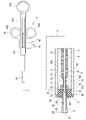
- FIG. 1 is an overall view of an endoscopic treatment instrument according to a first embodiment of the present invention
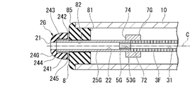
- FIG. 1 is a partial cross-sectional view of an endoscopic treatment instrument according to a first embodiment of the present invention
- FIG. 1 is a cross-sectional view of a main part of an endoscopic treatment instrument according to a first embodiment of the present invention
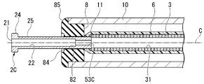
- FIG. 11 is a cross-sectional view of a main part of a modified endoscope treatment instrument
- FIG. 11 is a cross-sectional view of a main part of a modified endoscope treatment instrument
- FIG. 11 is a cross-sectional view of a main part of a modified endoscope treatment instrument
- FIG. 11 is a cross-sectional view of a main part of a modified endoscope treatment instrument
- FIG. 11 is a cross-sectional view of a main part of a modified endoscope treatment instrument
- FIG. 11 is a cross-sectional view of a main part of a modified endoscope treatment instrument
- FIG. 11
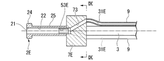
- FIG. 11 is a cross-sectional view of a main part of a modified endoscope treatment instrument;
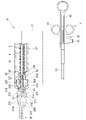
- FIG. 9 is a view seen from line IX-IX in FIG. 8; It is an overall view of an endoscopic treatment instrument according to a second embodiment of the present invention.
- FIG. 4 is a cross-sectional view of a main part of an endoscopic treatment instrument according to a second embodiment of the present invention;
- FIG. 11 is a cross-sectional view of a main part of a modified endoscope treatment instrument;
- FIG. 11 is a cross-sectional view of a main part of a modified endoscope treatment instrument;
- FIG. 11 is a cross-sectional view of a main part of a modified endoscope treatment instrument;
- FIG. 11 is a cross-sectional view of a main part of a modified endoscope treatment instrument;
- FIG. 1 is an overall view of an endoscope treatment instrument 1 according to this embodiment.
- FIG. 2 is a cross-sectional view of a main part of the endoscopic treatment instrument 1. As shown in FIG. In FIG. 2, the distal end portion is shown enlarged from the proximal portion.
- the endoscopic treatment instrument 1 is used by being inserted into a channel of an endoscope (not shown). As shown in FIG. 1, the endoscope treatment instrument 1 has a treatment section 2 at its distal end and an operation section 4 at its proximal end.
- the endoscopic treatment instrument 1 has a sheath 10, an operating wire 3, a high-frequency knife 2 (hereinafter simply referred to as "knife"), and an operating section 4.
- An operating portion 4 is provided at the proximal end of the flexible sheath 10 .
- a knife 2 is provided at the distal end of the operating wire 3 , and the operating wire 3 is passed through the inside of the sheath 10 .
- the knife 2 and the operation wire 3 are provided so as to be able to advance and retreat with respect to the sheath 10 as the operation portion 4 is operated.
- the knife 2 is energized with a high-frequency current through the operating portion 4 and the operating wire 3, and is configured to be able to incise tissue or the like.
- a water supply conduit is formed in the endoscope treatment instrument 1 from the operation portion 4 side to the distal end of the knife 2 .
- the endoscopic treatment instrument 1 is configured to supply liquid to a water supply conduit and supply water from the distal end of the knife 2 .
- the operation wire 3 is made of, for example, a conductive metal material such as stainless steel.
- a first conduit 31 is formed in the operation wire 3 over the entire length.
- the operation wire 3 is, for example, a close-wound coil.
- the operation wire 3 is covered with an insulating inner tube 6 over its entire length.
- the sheath 10 is made of an electrically insulating material such as tetrafluoroethylene.
- the outer diameter of the sheath 10 is set to a size that allows it to be inserted through a channel of an endoscope (not shown).
- An operating wire 3 is passed through the sheath 10 .
- the operation wire 3 can move forward and backward along the longitudinal axis C of the sheath 10 .
- the sheath 10 and the operation wire 3 constitute an insertion portion that is inserted through the channel of the endoscope.
- An insulating tip 8 is inserted into the distal opening of the sheath 10 .
- the insulating tip 8 is fixed to the distal end of the sheath 10 with an adhesive (not shown) or the like.
- the insulating chip 8 is made of, for example, a heat-resistant and insulating material such as ceramics or resin.
- the insulating tip 8 is formed with an insertion hole 82 communicating with the inner space of the sheath 10 and opening distally.
- a stepped portion 83 is formed by increasing the diameter of the opening of the insertion hole 82. As shown in FIG. It has a recess 84 recessed proximally from the distal end face of the insulating tip 8 .
- the outer diameter of the proximal portion of the insulating tip 8 is large enough to be inserted into the distal end of the sheath 10 .
- the distal end of the insulating tip 8 is formed with a large diameter portion 85 having a larger diameter than the proximal portion.
- the outer diameter of the large diameter portion 85 is approximately equal to the outer diameter of the sheath 10 .
- the outer peripheral portion on the distal side of the large diameter portion 85 has a curved surface.
- the operating section 4 is provided at the proximal portion of the sheath 10.
- the operation section 4 includes an operation main body 43 and a slider 44 .
- the slider 44 is slidably provided along the longitudinal axis C with respect to the operation body 43 . By moving the slider 44 back and forth with respect to the operation main body 43 , the knife 2 can be moved back and forth with respect to the sheath 10 .
- the operation body 43 is fixed to the proximal end of the sheath 10.
- a slit 431 is formed along the longitudinal axis C in the operating body 43 .
- the slider 44 can slide along the slit 431 with respect to the operation body 43 .
- the proximal end of the operation body 43 is provided with a ring 432 for finger hooking.
- a finger hook ring 442 is provided on the slider 44 .
- the slider 44 is provided with an electrical connector 42 .
- the electrical connector 42 is electrically connected to a high-frequency power supply (not shown).
- a proximal end of the operating wire 3 is electrically connected to an electrical connector 42 .
- FIG. 3 is a cross-sectional view of the distal end of slider 44 along longitudinal axis C.
- the slider 44 is formed with an insertion hole 441 for the operation wire 3 .
- a proximal end portion of the operation wire 3 is inserted into the insertion hole 441, and the proximal end of the operation wire 3 is fixed.
- a pair of projections 443 for fixing the operation wire 3 are formed in the insertion hole 441 .
- the protrusion 443 protrudes in a direction perpendicular to the longitudinal axis C from the inner surface of the insertion hole 441 .
- the convex portion 443 is a substantially cylindrical projection. The protrusions 443 protrude to such an extent that the outer peripheral surface of the proximal end portion of the operation wire 3 inserted into the insertion hole 441 contacts the pair of protrusions 443 .
- the slider 44 is provided with a liquid feed cap 41.
- the liquid-sending mouthpiece 41 is configured such that liquid-sending means such as a syringe or a water-sending tube extended from a water-sending pump can be detachably attached.
- the liquid feed mouthpiece 41 has an injection port 411 .
- the slider 44 is formed with an injection path 412 that communicates between the liquid feed cap 41 and the insertion hole 441 .
- An opening 33 for injecting liquid is formed at the proximal end of the operating wire 3 .
- the opening 33 is an opening that communicates with the inside and outside of the operation wire 3 .
- the operation wire 3 is fixed to the insertion hole 441 at a position where the insertion hole 441 and the opening 33 face each other. As a result, the liquid feed port 411 is communicated with the liquid feed conduit 31 of the operation wire 3 .
- An O-ring 444 is attached to each protrusion 443 .
- the O-ring 444 keeps the space between the operation wire 3 and the protrusion 443 watertight. The O-ring 444 prevents the liquid from leaking from the gap between the operation wire 3 and the convex portion 443 when the liquid is caused to flow from the liquid transfer nozzle 41 .
- a cylinder 5 is fixed to the distal end of the operation wire 3 .
- the cylindrical body 5 is, for example, a conductive cylindrical member such as stainless steel.
- a third conduit 53 is formed along the longitudinal axis C of the tubular body 5 .
- the opening area of the third conduit 53 is smaller than the opening area of the first conduit 31 of the operating wire 3 .
- a proximal end of the barrel 5 and a distal end of the operation wire 3 are fixed by a welded portion 11 .
- the distal end of the manipulating wire 3 , the proximal end of the tubular body 5 and the welded portion 11 are covered with the distal end of the inner tube 6 .
- a spiral groove 54 is formed on the outer peripheral surface of the cylindrical body 5 at an intermediate portion in the longitudinal axis C direction.
- the knife 2 is an electrode member. As shown in FIG. 2, knife 2 is connected to the distal end of manipulating wire 3 via barrel 5 and connector 7 .
- the knife 2 is made of a conductive material such as stainless steel.
- Knife 2 is a tubular member extending along longitudinal axis C. As shown in FIG. That is, the knife 2 is a tubular electrode with a second conduit 22 formed along the longitudinal axis C. As shown in FIG. Knife 2 has a large diameter portion 24 and a small diameter portion 25 .
- a large diameter portion 24 is located at the distal end of the knife 2 .
- the small diameter portion 25 is located in the region from the proximal end of the large diameter portion 24 to the proximal end 23 of the knife 2 .
- a second conduit 22 extending along the longitudinal axis C is formed inside the knife 2 .
- the second conduit 22 extends from the proximal end to the distal end of the knife 2 and opens at the proximal and distal ends of the knife 2 .
- the opening at the distal end of knife 2 is a water inlet 21 through which liquid is fed.
- the water supply port 21 opens to the large diameter portion 24 .
- the large diameter portion 24 is thicker in the radial direction than the small diameter portion 25 .
- the small diameter portion 25 is inserted through the insertion hole 82 of the insulating tip 8 .
- the outer diameter of the small diameter portion 25 is smaller than the inner diameter of the recess 84 on the distal side of the stepped portion 83 in the insertion hole 82 of the insulating tip 8 .
- the opening area of the recess 84 is larger than the area of the large diameter portion 24 .
- the knife 2 is inserted into the insulating tip 8 so as to be able to move forward and backward. When the knife 2 is retracted, the large diameter portion 24 enters the recess 84 .
- the distal end of the barrel 5 is inserted into the second conduit 22 of the knife 2.
- the cylindrical body 5 and the knife 2 are connected by a connector 7 .
- the connector 7 is made of a conductive metal material such as stainless steel.
- the connector 7 is formed with an insertion hole 72 penetrating along the longitudinal axis C. As shown in FIG. A spiral groove 71 is formed on the inner peripheral surface of the insertion hole 72 at the proximal end of the connector 7 .
- the inner peripheral surface of the distal end portion 721 of the insertion hole 72 of the connector 7 has an opening dimension capable of inserting the small-diameter portion 25 of the knife 2 described later.
- the proximal end portion of the knife 2 is inserted into the distal end portion 721 of the insertion hole 72, and the knife 2 and the connector 7 are fixed.
- the cylindrical body 5 is inserted into the insertion hole 72 from the proximal side of the connector 7 and screwed together by the spiral grooves 54 and 71 .
- the distal end of the tubular body 5 protrudes further distally than the distal end of the connector 7 .
- the proximal end 23 of the knife 2 is inserted into the distal end portion 721 of the insertion hole 72 while the connector 7 and the cylindrical body 5 are screwed together.
- the connector 7 and the cylindrical body 5 are fixed with screws is shown, but the method of connecting the connector and the cylindrical body is not limited to screwing.
- a configuration in which the connector and the cylindrical body are joined by an adhesive or welding may be used.
- the knife 2 is connected to the electrical connector 42 through the connector 7, the cylinder 5, the welded portion 11, and the operating wire 3. As a result, the knife 2 is energized through the operating wire 3 , welded portion 11 , connector 7 and barrel 5 from the high-frequency power supply connected to the electrical connector 42 .
- the opening area of the third conduit 53 of the barrel 5 is smaller than the opening areas of the first conduit 31 of the operating wire 3 and the second conduit 22 of the knife 2 . Therefore, the liquid flow path from the operating wire 3 to the water supply port 21 of the knife 2 is once narrowed by the third conduit 53 . As a result, the liquid supplied to the first pipeline 31 of the operating wire 3 passes through the third pipeline 53, thereby increasing the water pressure. The liquid with increased water pressure passes through the second conduit 22 and is sent from the water inlet 21 of the knife 2. - ⁇ As a result, even if the water pressure of the liquid supplied to the first pipeline 31 is low, the water force in the second pipeline 22 can be increased, and the water can be supplied from the water supply port 21 in a state of increasing the water force.
- a user such as an operator puts fingers into the ring 432 of the operation main body 31 and the ring 442 of the slider 44 to move the slider 44 with respect to the operation main body 43 in the direction along the longitudinal axis C. slide it with one hand to operate.
- the operation wire 3 is moved distally with respect to the sheath 10 by the operation of moving the slider 44 distally with respect to the operation main body 43 . Accordingly, the knife 2 protrudes distally beyond the insulating tip 8 .
- the distal end surface 74 of the connector 7 contacts the proximal end 81 of the insulating tip 8 as shown in FIG.
- the knife 2 is protruded to the maximum protruding position. That is, the projecting position of the knife 2 is determined by the contact of the connector 7 with the insulating tip 8 .
- a state in which the connector 7 abuts against the insulating tip 8 and the knife 2 protrudes most distally is referred to as a protruding state.
- the distal portion of the small diameter portion 25 of the knife 2 can be protruded distally beyond the sheath 10 through the insertion hole 82 of the insulating tip 8 .
- a liquid such as physiological saline is supplied to the first pipe line 31 from the injection port 411 of the liquid feed mouthpiece 41 .
- the liquid is fed distally from the water supply port 21 through the first conduit 31 of the operating wire 3 , the third conduit 53 of the barrel 5 , and the second conduit 22 of the knife 2 .
- the operation wire 3 is retracted proximally with respect to the sheath 10 by moving the slider 44 proximally with respect to the operation main body 43 .
- the large diameter portion 24 comes into contact with the concave portion 84 of the insulating tip 8 .
- the small-diameter portion 25 of the knife 2 is accommodated in the inner space 10S of the sheath 10, and positioned in a retracted state in which the operation wire 3 is retracted on the proximal side.
- the distal portion of the sheath 10 of the endoscopic treatment instrument 1 is protruded from the channel of the endoscope, and the knife 2 is opposed to the lesioned mucous membrane portion, which is the target site for treatment in the body cavity, for example.
- a syringe or water supply tube (not shown) is attached to the injection port 411 of the liquid supply mouthpiece 41 .
- the user presses the knife 2 against the mucous membrane of the lesion and supplies physiological saline contained in a syringe or a water pump to the first conduit 31 of the operating wire 3 .
- the knife 2 may be in a projected state or a retracted state.
- Physiological saline is supplied to the distal side from the water supply port 21 through the water supply conduit.
- the liquid supplied to the first conduit 31 passes through the third conduit 53 and then passes through the second conduit 22 and is sent from the water supply port 21 .
- the third pipeline 52 has a smaller opening area than the first pipeline 31 .
- the liquid supplied to the first pipeline 31 becomes stronger as it passes through the third pipeline 53 . Therefore, water can be fed from the water feed port 21 in a state where the water force is strong. As a result, water is supplied while pressing the water supply port 21 against the mucous membrane and submucosa of the lesion to raise the lesion.
- a high-frequency current is applied to the knife 2 through the electrical connector 42, the operating wire 3, and the connector 7 from a high-frequency power supply device (not shown) connected to the electrical connector 42 of the operation section 4.
- the mucosa (tissue) in contact with the knife 2 is incised.
- the knife 2 is brought into contact with the incision made around the lesioned mucous membrane to excise and peel the lesioned mucous membrane entirely.
- Body fluids such as mucus and blood may enter the second conduit 22 of the knife 2 from the water supply port 21 due to capillarity or the like when incising the mucosa or performing a procedure to coagulate the bleeding point.
- the mucus or blood adhering to the inside of the second conduit 22 due to the incision or peeling by the knife 2 may be scorched by the heat of the high-temperature knife 2 .
- the water supply conduit of the second conduit 22 narrows, making it difficult to supply water.
- the water is sent through the third pipe line 53 under a strong water force to remove the charred deposits in the second pipe line 22.
- the liquid that has been strengthened in the third conduit 53 is sent through the second conduit 22 and from the water supply port 21 .
- the charred deposits inside the second pipeline 22 are peeled off from the inner peripheral surface of the second pipeline 22 by the liquid pressure and discharged from the water supply port 21 .
- the third pipeline 53 is provided between the first pipeline 31 and the water supply port 21 .
- the opening area of the third pipeline 53 is smaller than the opening areas of the first pipeline 31 and the second pipeline 22 .
- the liquid supplied to the first pipeline 31 passes through the third pipeline 53, so that the force of the liquid can be increased, and the water can be supplied from the water supply port 21 with the force increased.
- the endoscopic treatment instrument 1 even if the output of the syringe or the water pump that supplies the liquid to the first conduit 31 is small, the water can be supplied from the water supply port 21 in a strong state.
- the third conduit 53 having an opening area smaller than that of the first conduit 31 and the second conduit 22 is connected from the distal end portion of the operation wire 3 to the water supply port 21 .
- the endoscopic treatment instrument 1 by feeding water from the third conduit 53 with a strong force, it is possible to easily remove charred deposits in the second conduit 22. Therefore, it is possible to prevent clogging of the second pipeline 22 with the deposits.
- the manner in which the third conduit 53 is provided is not limited to the above example.
- the endoscopic treatment instrument may be modified, for example, as shown in FIGS. 4 to 9 .
- the same parts as those of the first embodiment are denoted by the same reference numerals, and descriptions thereof are omitted, and only different points are described.
- the example shown in FIG. 4 is an example in which the configurations of the operation wire 3A, the connector 7A and the tubular body 5A are different from those of the first embodiment.
- the operating wire 3A is a flexible tube made of a conductive material.
- the inner tube 6 is not an essential component because the first pipeline 31 of the operation wire 3A can be kept watertight.
- the third pipeline 53A may be positioned between the distal end portion of the operation wire 3 and the water supply port 21 . For example, as shown in FIG.
- the barrel 5 is fixed to the operation wire 3
- the connector 7 is fixed to the proximal end of the knife 2, and the connector 7 and the barrel 5 are screwed together to connect the barrel.
- An example in which the knife 2 is connected is shown.
- the manner in which the operating wire 3 and the knife 2 are connected by the connector 7 is not limited to this example.
- the distal end of the operating wire 3A and the proximal end of the knife 2A may be inserted through the insertion hole 72 of the connector 7A and fixed.
- the operating wire 3A and the knife 2A can be energized by coming into contact with the connector 7A.
- the inner tube 6 of the first embodiment may not be provided.
- water can be supplied from the water supply port 21 in a state in which the water pressure of the liquid is increased in the third conduit 53A and the water force is increased.
- the example shown in FIG. 5 is an example different from the first embodiment in the configuration of the operation wire 3B, the connector 7B, the cylinder 5B, the insulating tip 8B, and the proximal end of the knife 2B.
- the configurations of the operation wire 3B, the connector 7B, and the cylindrical body 5B are the same as those of the modification shown in FIG.
- the proximal end 26 of knife 2B has a larger diameter than the smaller diameter portion 25 .
- a stepped portion 27 is formed between the small diameter portion 25 and the proximal end portion 26 . In the direction orthogonal to the longitudinal axis C, the thickness of the proximal end portion 26 is thicker than the thickness of the small diameter portion 25 .
- the second pipe line 22 of the proximal end portion 26 is formed with a housing portion for the tubular body 5B. At the proximal end portion 26, the opening area of the second pipe line 22 is slightly larger than that of the other regions, so that the tubular body 5B can be fitted therein.
- a recess 821 recessed toward the distal side is formed at the proximal end of the insulating tip 8B.
- the concave portion 821 has an opening dimension larger than that of the insertion hole 82 of the insulating chip 8, and a stepped portion 822 is formed.
- the step 27 of the proximal end 26 of the knife 2B abuts the step 822 of the recess 821 of the insulating tip 8B.
- the treatment instrument of the modified example shown in FIG. 5 can supply liquid from the water supply port 21 in a state in which the water pressure is increased in the third conduit 53B, as in the first embodiment.
- the connector 7 and cylinder 5 shown in the first embodiment are not essential components.
- the second pipeline 22 and the third pipeline 53C may be continuously formed in the knife 2C.
- the knife 2 ⁇ /b>C has a third conduit 53 ⁇ /b>C having an opening area smaller than that of the second conduit 22 and the first conduit 31 of the operating wire 3 on the proximal end side of the second conduit 22 .
- the proximal end portion of the knife 2 and the distal end portion of the operating wire 3 may be fixed by the welded portion 11 .
- the treatment instrument of the modification shown in FIG. 6 can supply liquid from the water supply port 21 in a state in which the force of the liquid is increased in the third conduit 53C.
- the third pipe line 53D is formed integrally with the knife 2D.
- the aspect of the third pipeline 53D is the same as the modification shown in FIG.
- An inclined surface 29 is formed between the proximal end of the third conduit 53D and the proximal end of the knife 2D.
- the inclined surface 29 is a tapered inclined surface that decreases in diameter from the proximal end of the knife 2D toward the proximal end of the third conduit 53D.
- the first pipeline 31 may be provided separately from the operation wire.
- the first pipeline and the third pipeline are not limited to one pipeline each.
- a plurality of liquid feeding tubes 9 may be provided independently of the operating wire 3 .
- three liquid-sending tubes 9 are arranged around the operation wire 3 .
- a distal end of the operating wire 3 is fixed to the connector 7E.
- the proximal end of knife 2E is fixed to connector 7E.
- a connection conduit 73 is formed in the connector 7E.
- connection pipes 73 are formed in the same number as the liquid-sending pipes 9 .
- a proximal end of each connection conduit 73 is connected to each liquid transfer tube 9 .
- the connecting conduit 73 has three openings spaced apart in the circumferential direction of the connector 7E at the proximal end of the connector 7E and slopes toward the distal end of the connector 7E.
- the three connecting lines 73 meet at the distal end of the connector 7E.
- the third pipe line 53E is formed on the distal side of the confluence of the three liquid feeding pipes 9. As shown in FIG.
- a third conduit 53E is formed at the connection between the connector 7E and the incision 2E.
- the opening area of the third pipeline 53E is smaller than the opening area of the confluence portion of the connection pipeline 73 .
- FIG. 10 An endoscope treatment instrument 1F according to a second embodiment will be described with reference to FIGS. 10 to 12.
- the endoscopic treatment instrument is not limited to a high-frequency knife, and can be applied to an endoscopic treatment instrument having the functions of supplying water and electricity.
- the endoscopic treatment instrument 1F according to the present embodiment is an example in which the treatment portion is forceps 2F.
- the configurations of the operating portion 4, the sheath 10, the operating wire 3, and the inner tube 6 are the same as in the first embodiment.
- the forceps 2F has a pair of forceps members 211, 212, a pair of link members 213, 214, a plurality of rotating shafts 216, 217, 218, a shaft member 215, a cover 228, and a stopper 227.
- the forceps 2F has a known link mechanism.
- the cover 228 and the stopper 227 are integrally formed.
- An insertion hole 229 is formed through the stopper 227 in the longitudinal axis C direction.
- a second pipe line 22 ⁇ /b>F is formed inside the shaft member 215 .
- a proximal end of the shaft member 215 is fixed to a distal end of the operating wire 3 .
- a cylindrical body 5F is inserted into the proximal end of the second conduit 22F.
- a third pipeline 53F of the cylindrical body 5F is arranged on the distal side of the first pipeline 31 of the operation wire 3, and a second pipeline 22F is formed on the distal side of the third pipeline 53F.
- the link members 213 and 214 are connected to the distal end of the shaft member 215 via the proximal rotation shaft 218 .
- the distal rotating shaft 216 is connected to the cover 228 through which the pair of forceps members 211 and 212 are inserted.
- a through hole 216 ⁇ /b>F passing through the distal pivot shaft 216 along the longitudinal axis C is formed.
- the through hole 216F has an opening area equivalent to that of the second pipeline 22F inside the shaft member 215, and functions as an extension pipeline of the second pipeline 22F. Therefore, the distal end of the through hole 216F functions as the water supply port 21F.
- An enlarged diameter portion 823 is formed in the middle portion of the insertion hole 82 in the direction of the longitudinal axis C of the insulating tip 8F.
- the stopper 227 is accommodated in the enlarged diameter portion 823 .
- the stopper 227 restricts the movement range of the cover 228 in the direction of the longitudinal axis C with respect to the insulating tip 8F.
- the shaft member 215 is advanced and retracted with respect to the cover 228.
- a pair of forceps members 211 , 212 are rotatably connected to cover 228 by distal rotation shaft 216 .
- the proximal rotation shaft 218 approaches the distal rotation shaft 216, and the pair of forceps members 211 and 212 are opened.
- the liquid is supplied through the liquid-sending mouthpiece 41 as in the first embodiment. Liquid is delivered from the distal end of shaft member 215 through first conduit 31, third conduit 53F, and second conduit 22F.
- the liquid supplied from the distal end of the shaft member 215 passes through the water supply port 21F provided at the distal end of the through hole 216F of the distal rotation shaft 216, and flows through the open forceps members 211 and 212. Water is sent from between to the distal side.
- the proximal pivot shaft 218 moves proximally and separates from the distal pivot shaft 216, closing the pair of forceps members 211 and 212 as shown in FIG.
- the liquid can be fed from the water feed port 21F in a state in which the force of the liquid is increased in the third conduit 53F.
- the cylindrical body of this embodiment is not limited to the above configuration.
- the modifications shown in FIGS. 12 and 13 may be adopted.
- the cylinder 5F is provided at the distal end of the shaft member 215.
- the third conduit 53F is positioned on the distal end side of the shaft member 215 .
- the distal end of the cylindrical body 5F protrudes further distally than the distal end of the shaft member 215.
- the third pipeline 53F is in a state where the water force is increased, and the water outlet 21F provided at the distal end of the through-hole 216F is opened. Water is fed to the distal side from between the pair of forceps members 211 and 212 that are in contact with each other.
- the liquid can be delivered with increased force at the distal portion of the device.
- the modification shown in FIG. 13 is an example in which a cylinder 5G is longer than the cylinder 5F of the modification shown in FIG.
- the elongated tubular body 5G may protrude to the vicinity of the distal rotation shaft 216.
- the pair of forceps members 211 and 212 are opened, the distal end of the tubular body 5G protrudes further to the distal side than the distal rotation shaft 216.
- water can be fed with a stronger water force on the more distal side.
- water can be fed from the water feed port 21G in a state in which the force of the liquid is increased in the third pipeline 53G.
- examples of the high-frequency knives 2A to 2E are shown as endoscope treatment tools, but the endoscope treatment tools are not limited to the above examples.
- it may be an endoscopic treatment tool illustrated in FIGS. 14 and 15 .
- a high-frequency treatment instrument 2G shown in FIGS. 14 and 15 differs from the above-described high-frequency knives 2A to 2E in the configuration of the distal end portion.
- a large-diameter portion 24G of the high-frequency treatment instrument 2G has a distal end member 244 and a conducting portion 241. As shown in FIG. Distal end member 244 is located at the distal end of large diameter portion 24G.
- the distal end member 244 is made of an insulating spherical member such as zirconia or ceramics.
- the conducting portion 241 is provided at the proximal end portion of the distal end member 244 .
- the conducting portion 241 is made of, for example, a conductive metal material such as stainless steel, and has an annular proximal end portion 242 and a tubular portion 243 .
- a tubular portion 243 projects distally from the proximal end 242 .
- a tubular portion 243 is inserted into and secured to the distal end member 244 .
- a distal end portion of the small diameter portion 25G is inserted into the cylindrical portion 243 and fixed.
- An outer peripheral edge (outer edge portion) 245 of the proximal end portion 242 of the conducting portion 241 is exposed along the outer peripheral surface of the proximal end portion of the distal end member 244 .
- High-frequency current is applied to the conducting portion 241 through the operating wire 3G, the connector 7G, and the small diameter portion 25G.
- the outer peripheral edge 245 of the proximal end portion 242 of the current-carrying portion 241 is configured to be in contact with tissue or the like to incise the tissue or the like when energized.
- the tubular body 5G is inserted into the proximal end portion of the small diameter portion 25G.
- the liquid that has passed through the first conduit 31 is conveyed through the third conduit 53G in a state where the water pressure is increased, and is then conveyed from the water supply port 21 through the second conduit 22G.
- the fluid was physiological saline, but the fluid is not limited to this, and may be a chemical solution or the like.
- the liquid can be fed from the water feed port 21 while the force of the liquid is increased in the third conduit 53 . Therefore, even if the water supply means connected to the liquid supply nozzle 41 of the operation unit 4 is a low-pressure or low-flow syringe, a low-performance water supply pump, or the like, the liquid can be supplied from the water supply port 21 with a strong water force. Therefore, it is not necessary to replace the high-frequency knife and the local injection needle to perform local injection, and the treatment time can be shortened.
- an endoscopic treatment instrument capable of supplying a liquid such as a drug solution or physiological saline with a strong water force from the distal end of the treatment instrument without using a high-performance water pump.
Landscapes
- Health & Medical Sciences (AREA)
- Surgery (AREA)
- Engineering & Computer Science (AREA)
- Life Sciences & Earth Sciences (AREA)
- Biomedical Technology (AREA)
- Molecular Biology (AREA)
- Nuclear Medicine, Radiotherapy & Molecular Imaging (AREA)
- Plasma & Fusion (AREA)
- Physics & Mathematics (AREA)
- Heart & Thoracic Surgery (AREA)
- Medical Informatics (AREA)
- Otolaryngology (AREA)
- Animal Behavior & Ethology (AREA)
- General Health & Medical Sciences (AREA)
- Public Health (AREA)
- Veterinary Medicine (AREA)
- Surgical Instruments (AREA)
- Endoscopes (AREA)
Priority Applications (4)
| Application Number | Priority Date | Filing Date | Title |
|---|---|---|---|
| PCT/JP2021/002302 WO2022157942A1 (ja) | 2021-01-22 | 2021-01-22 | 内視鏡用処置具 |
| JP2022576914A JP7473691B2 (ja) | 2021-01-22 | 2021-01-22 | 内視鏡用処置具 |
| CN202180090880.4A CN116710012A (zh) | 2021-01-22 | 2021-01-22 | 内窥镜用处置器具 |
| JP2024062997A JP7738124B2 (ja) | 2021-01-22 | 2024-04-09 | 内視鏡用処置具 |
Applications Claiming Priority (1)
| Application Number | Priority Date | Filing Date | Title |
|---|---|---|---|
| PCT/JP2021/002302 WO2022157942A1 (ja) | 2021-01-22 | 2021-01-22 | 内視鏡用処置具 |
Publications (1)
| Publication Number | Publication Date |
|---|---|
| WO2022157942A1 true WO2022157942A1 (ja) | 2022-07-28 |
Family
ID=82549621
Family Applications (1)
| Application Number | Title | Priority Date | Filing Date |
|---|---|---|---|
| PCT/JP2021/002302 Ceased WO2022157942A1 (ja) | 2021-01-22 | 2021-01-22 | 内視鏡用処置具 |
Country Status (3)
| Country | Link |
|---|---|
| JP (2) | JP7473691B2 (https=) |
| CN (1) | CN116710012A (https=) |
| WO (1) | WO2022157942A1 (https=) |
Citations (3)
| Publication number | Priority date | Publication date | Assignee | Title |
|---|---|---|---|---|
| WO2014061701A1 (ja) * | 2012-10-17 | 2014-04-24 | オリンパスメディカルシステムズ株式会社 | 高周波ナイフ |
| EP3639780A1 (en) * | 2017-06-13 | 2020-04-22 | Fine Medix Co., Ltd. | Endoscope hybrid knife |
| WO2020103350A1 (zh) * | 2018-11-21 | 2020-05-28 | 南微医学科技股份有限公司 | 一种医用连接装置 |
Family Cites Families (4)
| Publication number | Priority date | Publication date | Assignee | Title |
|---|---|---|---|---|
| US7763019B2 (en) * | 2006-12-04 | 2010-07-27 | Olympus Medical Systems Corp. | Electrosurgical instrument |
| JP5613518B2 (ja) * | 2010-09-30 | 2014-10-22 | 富士フイルム株式会社 | 内視鏡用処置具 |
| JP5775989B1 (ja) * | 2013-10-09 | 2015-09-09 | オリンパス株式会社 | 内視鏡用高周波処置具 |
| CN108601602B (zh) * | 2016-02-02 | 2021-04-13 | 奥林巴斯株式会社 | 内窥镜处置器具 |
-
2021
- 2021-01-22 WO PCT/JP2021/002302 patent/WO2022157942A1/ja not_active Ceased
- 2021-01-22 CN CN202180090880.4A patent/CN116710012A/zh active Pending
- 2021-01-22 JP JP2022576914A patent/JP7473691B2/ja active Active
-
2024
- 2024-04-09 JP JP2024062997A patent/JP7738124B2/ja active Active
Patent Citations (3)
| Publication number | Priority date | Publication date | Assignee | Title |
|---|---|---|---|---|
| WO2014061701A1 (ja) * | 2012-10-17 | 2014-04-24 | オリンパスメディカルシステムズ株式会社 | 高周波ナイフ |
| EP3639780A1 (en) * | 2017-06-13 | 2020-04-22 | Fine Medix Co., Ltd. | Endoscope hybrid knife |
| WO2020103350A1 (zh) * | 2018-11-21 | 2020-05-28 | 南微医学科技股份有限公司 | 一种医用连接装置 |
Also Published As
| Publication number | Publication date |
|---|---|
| JP2024074967A (ja) | 2024-05-31 |
| JPWO2022157942A1 (https=) | 2022-07-28 |
| JP7738124B2 (ja) | 2025-09-11 |
| JP7473691B2 (ja) | 2024-04-23 |
| CN116710012A (zh) | 2023-09-05 |
Similar Documents
| Publication | Publication Date | Title |
|---|---|---|
| CN105073049B (zh) | 内窥镜用高频处理器具 | |
| CN108272503B (zh) | 一种可双通道注液的双极高频电刀 | |
| CN104507406B (zh) | 高频刀 | |
| EP3965678B1 (en) | Medical device | |
| US20120245580A1 (en) | Medical ablation system and method of use | |
| CN108742832A (zh) | 医用电刀 | |
| JP2003052713A (ja) | 内視鏡用処置装置 | |
| CN111658128A (zh) | 一种具有多功能的高频刀具 | |
| US20230137591A1 (en) | Endoscope treatment tool, and treatment method | |
| CN100528095C (zh) | 高频处置工具 | |
| JP4690410B2 (ja) | 内視鏡用処置具 | |
| JP7794890B2 (ja) | 内視鏡用処置具 | |
| JP4965416B2 (ja) | 高周波処置具 | |
| CN101227864A (zh) | 内窥镜用处理器具 | |
| WO2022157942A1 (ja) | 内視鏡用処置具 | |
| CN112261913A (zh) | 用于组织凝结的系统和方法 | |
| CN116059509B (zh) | 内窥镜用处置器具 | |
| JP2025520473A (ja) | インターフェースジョイント | |
| CN209153964U (zh) | 一种用于切开刀的密封组件 | |
| JP7659037B2 (ja) | 内視鏡用処置具 | |
| JP2023067806A (ja) | 内視鏡用処置具 | |
| CN118453092A (zh) | 经尿道的前列腺组织消融系统 |
Legal Events
| Date | Code | Title | Description |
|---|---|---|---|
| 121 | Ep: the epo has been informed by wipo that ep was designated in this application |
Ref document number: 21921051 Country of ref document: EP Kind code of ref document: A1 |
|
| WWE | Wipo information: entry into national phase |
Ref document number: 202180090880.4 Country of ref document: CN |
|
| ENP | Entry into the national phase |
Ref document number: 2022576914 Country of ref document: JP Kind code of ref document: A |
|
| NENP | Non-entry into the national phase |
Ref country code: DE |
|
| 122 | Ep: pct application non-entry in european phase |
Ref document number: 21921051 Country of ref document: EP Kind code of ref document: A1 |