WO2022153785A1 - フィルムロール及びフィルムロールの製造方法 - Google Patents
フィルムロール及びフィルムロールの製造方法 Download PDFInfo
- Publication number
- WO2022153785A1 WO2022153785A1 PCT/JP2021/046677 JP2021046677W WO2022153785A1 WO 2022153785 A1 WO2022153785 A1 WO 2022153785A1 JP 2021046677 W JP2021046677 W JP 2021046677W WO 2022153785 A1 WO2022153785 A1 WO 2022153785A1
- Authority
- WO
- WIPO (PCT)
- Prior art keywords
- film
- optical film
- film roll
- roll
- stretching
- Prior art date
- Legal status (The legal status is an assumption and is not a legal conclusion. Google has not performed a legal analysis and makes no representation as to the accuracy of the status listed.)
- Ceased
Links
Images





Classifications
-
- B—PERFORMING OPERATIONS; TRANSPORTING
- B29—WORKING OF PLASTICS; WORKING OF SUBSTANCES IN A PLASTIC STATE IN GENERAL
- B29C—SHAPING OR JOINING OF PLASTICS; SHAPING OF MATERIAL IN A PLASTIC STATE, NOT OTHERWISE PROVIDED FOR; AFTER-TREATMENT OF THE SHAPED PRODUCTS, e.g. REPAIRING
- B29C55/00—Shaping by stretching, e.g. drawing through a die; Apparatus therefor
- B29C55/02—Shaping by stretching, e.g. drawing through a die; Apparatus therefor of plates or sheets
-
- C—CHEMISTRY; METALLURGY
- C08—ORGANIC MACROMOLECULAR COMPOUNDS; THEIR PREPARATION OR CHEMICAL WORKING-UP; COMPOSITIONS BASED THEREON
- C08J—WORKING-UP; GENERAL PROCESSES OF COMPOUNDING; AFTER-TREATMENT NOT COVERED BY SUBCLASSES C08B, C08C, C08F, C08G or C08H
- C08J5/00—Manufacture of articles or shaped materials containing macromolecular substances
- C08J5/18—Manufacture of films or sheets
-
- C—CHEMISTRY; METALLURGY
- C08—ORGANIC MACROMOLECULAR COMPOUNDS; THEIR PREPARATION OR CHEMICAL WORKING-UP; COMPOSITIONS BASED THEREON
- C08K—Use of inorganic or non-macromolecular organic substances as compounding ingredients
- C08K3/00—Use of inorganic substances as compounding ingredients
- C08K3/01—Use of inorganic substances as compounding ingredients characterized by their specific function
- C08K3/013—Fillers, pigments or reinforcing additives
-
- G—PHYSICS
- G02—OPTICS
- G02B—OPTICAL ELEMENTS, SYSTEMS OR APPARATUS
- G02B5/00—Optical elements other than lenses
- G02B5/30—Polarising elements
Definitions
- the present invention relates to a film roll and a method for producing a film roll. More specifically, the present invention relates to a film roll that has few winding failures during transportation and long-term storage and can maintain quality. The present invention also relates to a method for producing the film roll, which has a high production yield and a significantly reduced inspection load.
- optical protective films and optical functional films provided in image display devices such as liquid crystal displays (LCDs), organic electroluminescence displays (ELDs), and electronic papers are usually rolled. Since it is supplied to the next step, there is a demand for thinning the optical film as described above. Further, the optical film is also required to be longer and wider in order to improve production efficiency.
- LCDs liquid crystal displays
- ELDs organic electroluminescence displays
- electronic papers are usually rolled. Since it is supplied to the next step, there is a demand for thinning the optical film as described above. Further, the optical film is also required to be longer and wider in order to improve production efficiency.
- the air layer (air layer) taken into the film roll is deflated due to the air being released during product transportation or over time, and the film roll core is stuck. As a result, the core portion of the film roll becomes unusable waste, and the environmental load becomes large.
- the present inventor is in the process of examining the cause of the above problem in order to solve the above problem.
- the problem can be solved by controlling the film thickness of the optical film, the reflectance of the surface, and the like within a specific range, and have arrived at the present invention. That is, the above problem according to the present invention is solved by the following means.
- a film roll in which a single-layer optical film is wound The average maximum height difference (PV) ave1 of the film thickness within the range of 1000 mm in diameter is 0.15 to 0.40 ⁇ m around an arbitrary point in the optical film. Moreover, the film roll is characterized in that the ratio of the central portion to the end portion (outer diameter of the central portion / outer diameter of the end portion) of the film roll is 0.98 to 1.02.
- the average maximum height difference (PV) ave1 of the film thickness within the range of 1000 mm in diameter is 0.15 to 0.40 ⁇ m around an arbitrary point in the optical film.
- the a * value and the b * value defined by the CIE1976L * a * b * color system obtained from the reflectance of the surfaces of the central portion and the end portion of the film roll satisfy the following equation (1) (1). : -1.0 ⁇ (end a * -center a * ) + (end b * -center b * ) ⁇ 1.0
- the average maximum height difference (PV) ave2 of the film thickness measured in the following steps 1 to 3 diagonally with respect to the width direction of the optical film is 0.15 to 0.40 ⁇ m.
- Step 2 After the completion of the step 1, the same measurement as in the step 1 is performed until the total distance of the moving positions in the longitudinal direction reaches 1000 m, and the maximum film thickness in the oblique direction with respect to the width direction of the optical film is maximized. The height difference is further calculated.
- Step 3 From the maximum height difference of the thickness in the diagonal direction with respect to the width direction of the optical film obtained from steps 1 and 2, the average maximum height difference of the film thickness in the diagonal direction with respect to the width direction of the optical film ( PV) Calculate ave2 .
- Equation (2) in which d ave ⁇ m satisfies the following equation (2): 800 ⁇
- a method for producing a film roll which comprises flattening a film roll at a temperature as high as 50 to 200 ° C. with respect to the temperature inside the stretching furnace in the flattening treatment step.
- the flattening treatment is performed using an infrared (IR) heater, and Equation (3):
- the average value B of the amount of heat A at the center and the amount of heat at the end at a position 100 mm away from the infrared (IR) heater satisfies the following equation (3): 0.2 ⁇ (B / A) ⁇ 0.6
- Patent Document 1 when a person skilled in the art manufactures a film roll, the edge of the optical film is subjected to a nerling process from the viewpoint of industrial productivity, cost, etc., and an air layer (air) is formed. A means of winding the optical film while winding the layer) has been adopted.
- the main functions of the knurling processing portion are two functions, that is, the function of suppressing the sticking of the optical film by taking in the air layer (air layer) and the function of suppressing the unwinding of the film roll due to the physical unevenness. ..
- the above-mentioned air layer (air layer) suppresses the sticking of the optical films to each other, but during transportation by sea mail, truck, etc., or When stored in the customer's warehouse, the air in the air layer (air layer) is released over time, which interferes with the above two functions.
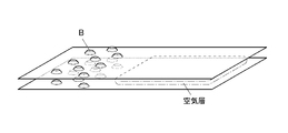
- FIG. 1A is a schematic view immediately after winding (immediately after manufacturing) of a conventional film roll whose end is knurled.
- FIG. 1B is an enlarged view of a part A of the end portion of the film roll in FIG. 1A.
- FIG. 1C is an enlarged cross-sectional view of the film of a part B of the uneven shape of the knurling process in FIG. 1B.
- FIG. 2 is a schematic view showing a state of deflection of the film roll after a lapse of a certain period of time.
- the film roll whose ends were knurled as shown in FIG. 1A was optically knurled.
- the end portion protrudes as shown in FIG. 1C, so that the roll diameter at the end portion is compared with the roll diameter at the center portion.
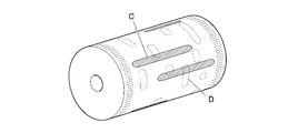
- FIG. 3 shows a schematic view showing the core side of the film roll of FIG. 2 on the film roll after a lapse of a certain period of time.
- the air in the air layer air layer
- the surface on the core side the surface on the core side
- several sticking parts sticking failure; part D in FIG. 3
- the length is added to the fine wrinkles (wrinkles) of the width as shown in FIG. Sticking in the width direction with a period (gradual failure; see part C in FIG. 3) occurs.
- the air layer (air layer) is appropriately taken into the film roll on which the single-layer optical film is wound, and the end portion is not subjected to nerling processing, and the entire contact surface where the optical films face each other is not applied.
- the problem was solved with the idea of reversing the conventional technique of dispersing the unwinding function by causing moderate and minute contact (at a level where sticking is not recognized).
- the average maximum height difference (PV) ave1 of the film thickness measured within the range of 1000 mm in diameter around an arbitrary point in the optical film is 0.15 to 0.
- This means is characterized in that it is 40 ⁇ m and the value (Dc / De) of the ratio of the outer diameter Dc of the central portion to the outer diameter De of the end portion of the film roll is 0.98 to 1.02.
- the film roll of the present invention is not subjected to the knurling process at the end portion, and the average maximum height difference of the film thickness of the entire surface of the film roll, that is, the film thickness difference is small. Therefore, the air layer (air layer) between the optical films becomes uniform, and the upper side of the film roll becomes flat. Although the lower side of the film roll is also affected by its own weight, the lower side can be suppressed by eliminating the upper side bending in the width direction.
- the stress in the circumferential direction (longitudinal direction) of the film roll becomes uniform, and in the width direction, the optical films stick to each other due to contact with each other centering on the convex portions of the optical films. Stress concentration due to is suppressed.
- the air layer (air layer) taken in at the time of winding does not suppress the contact of the entire width in the product part, but the edge of the optical film is not knurled.
- the unwinding function is also dispersed by controlling the average maximum height difference (PV) ave2 of the film thickness in the diagonal direction with respect to the width direction of the optical film in a specific range in consideration of the variation in the longitudinal direction. It is presumed that it was possible to provide a film roll that can maintain the quality with few winding failures during transportation and long-term storage. In addition, it is presumed that it was possible to provide a method for producing the film roll, which has a high production yield and a significantly reduced inspection load.
- the average maximum height difference (PV) ave2 of the film thickness in the diagonal direction with respect to the width direction of the optical film is less than 0.15, the sticking is recognized immediately after winding. If it is 0.40 or more, minute sticking due to variation occurs and the problem cannot be solved.
- FIG. 1A Schematic diagram of a film roll with knurled edges immediately after winding (immediately after manufacturing) An enlarged view of a part A of the end portion of the film roll in FIG. 1A.
- FIG. 1B is an enlarged cross-sectional view of the film of a part B of the uneven shape of the knurling process.
- Schematic diagram showing the state of deflection of a film roll after a certain period of time Schematic diagram showing how stress is applied to the surface on the core side of the film roll after a certain period of time has passed.
- Schematic of the film roll of the present invention Flow chart showing the flow of the manufacturing process of the solution casting film forming method
- Schematic diagram of an apparatus for manufacturing an optical film by a solution casting film forming method Top view schematically showing the internal configuration of the tenter stretching device Side view of three zones in the tenter stretching device Top view of the three zones in the tenter stretching device
- Schematic diagram of nozzle and heater installation parts when the three zones in the tenter stretching device are viewed from the front Schematic diagram showing the process of winding an optical film and the cross section of the film roll of the present invention after being wound.
- Flow chart showing the flow of the manufacturing process of the melt casting film forming method Schematic configuration diagram of an apparatus for manufacturing an optical film by the melt casting film forming method
- the film roll of the present invention is a film roll in which a single-layer optical film is wound, and has an average maximum height difference (P) of film thickness within a range of 1000 mm in diameter centered on an arbitrary point in the optical film.
- -V) ave1 is 0.15 to 0.40 ⁇ m, and the ratio of the central portion to the end portion (outer diameter of the central portion / outer diameter of the end portion) of the film roll is 0.98 to 1.02. It is characterized by that.
- the film roll of the present invention has a CIE1976L * a * b * a * value and b specified by the color system obtained from the reflectance of the surfaces of the central portion and the end portion of the film roll. * The value satisfies the above equation (1).
- the average maximum height difference (PV) ave2 of the film thickness measured in the order of steps 1 to 3 diagonally with respect to the width direction of the optical film is 0.15. It is preferably about 0.40 ⁇ m from the viewpoint of exhibiting the effect of the present invention.
- the average differential orientation angle ⁇ ave ° and the average differential film thickness d ave ⁇ m within the range of 1000 mm in diameter are calculated around an arbitrary point in the optical film, the average differential orientation angle ⁇ ave ° and the average differential film thickness are calculated. It is preferable that d ave ⁇ m satisfies the above formula (2) from the viewpoint of exhibiting the effect of the present invention.
- the optical film contains inorganic fine particles from the viewpoint of being able to adjust the surface of the optical film to an appropriate uneven state and imparting low birefringence, and from the viewpoint of improving heat resistance and storage stability and environmental stability. ..
- the width of the optical film is preferably 2400 to 3000 mm from the viewpoint of thinning and productivity.
- the length of the optical film is preferably 7500 to 10000 m from the viewpoint of thinning and productivity.
- the method for producing a film roll of the present invention is a method for producing a film roll for producing the film roll, and includes at least a stretching step of stretching an optical film in a stretching furnace and a flattening treatment step, and the flattening.
- the flattening treatment is performed at a temperature as high as 50 to 200 ° C. with respect to the temperature in the stretching furnace, and in the stretching step, the flattening treatment is performed using an infrared (IR) heater.
- IR infrared
- the film roll of the present invention is a film roll in which a single-layer optical film is wound, and has a film thickness within a range of 1000 mm in diameter centered on an arbitrary point in the optical film.
- Average maximum height difference (PV) ave1 is 0.15 to 0.40 ⁇ m, and the ratio of the center to the edge of the film roll (outer diameter of the center / outer diameter of the edge) is 0.98 to It is characterized by being 1.02.
- the "average maximum height difference (PV) ave1 of the film thickness of the optical film” is the maximum height of the peaks and valleys of the uneven shape of the thickness of the optical film measured and observed by the film thickness measurement described later.
- the average value of the differences is used to calculate the height difference between the highest part of the convex structure and the lowest part of the concave structure of the optical film by measuring the film thickness, and the average value is calculated as (P-).
- the "end” refers to a region within a range of 15 to 30 mm inside from the end of the optical film (roll) in the width direction.
- the "central portion” refers to the region portion of the optical film excluding both ends in the width direction.
- the "outer diameter” refers to the diameter of a circle formed at the outermost circumference of the roll, where the cross section perpendicular to the central axis (core) of the film roll is a circle. Therefore, the "outer diameter of the end portion” means the diameter (average value) of the circular cross section observed in the end region. Further, the “outer diameter of the central portion” means the diameter of the circular cross section observed at the central point of the central portion.
- the outer diameter at a position 30 mm from both ends in the width direction of the film roll was measured with a tape measure and used as the outer diameter of the end portion.
- the outer diameter of the end portion was taken as the average value of the outer diameters of both ends.
- Other methods can also be used to measure the outer diameter of the film roll.
- a laser of a laser displacement meter (LK-G5000 manufactured by Keyence) is placed outside the position 30 mm from both ends in the width direction of the film roll. It is also possible to measure the outer diameter by installing it so as to irradiate the diameter and the center position of the central part.
- the optical film of the present invention has an average maximum height difference (P-) of film thickness measured within a diameter of 1000 mm centered on an arbitrary point in the optical film.
- V) ave1 is 0.15 to 0.40 ⁇ m.
- the value (Dc / De) of the ratio of the outer diameter Dc of the central portion to the outer diameter De of the end portion of the film roll is 0.98 to 1.02.
- the film roll of the present invention is not subjected to the knurling process at the end portion, and the average maximum height difference of the film thickness of the entire surface of the film roll, that is, the film thickness difference is small. Therefore, the air layer (air layer) between the optical films becomes uniform, and the upper side of the film roll becomes flat. Although the lower side of the film roll is also affected by its own weight, the lower side can be suppressed by eliminating the upper side bending in the width direction.
- the stress in the circumferential direction (longitudinal direction) of the film roll becomes uniform, and in the width direction, the optical films stick to each other due to contact with each other centering on the convex portions of the optical films. Stress concentration due to is suppressed.
- the average maximum height difference (PV) ave2 of the film thickness measured in the following steps 1 to 3 diagonally with respect to the width direction of the optical film is 0.15 to 0.40 ⁇ m. It is preferable from the viewpoint of solving the problem according to the present invention by the above-mentioned action mechanism.
- Step 1 After measuring the film thickness at an arbitrary position on the end, measure the film thickness at a position moved 50 mm in the width direction and 620 mm in the longitudinal direction from the arbitrary position for each measurement, and repeat this until the other end. Calculate the maximum height difference in the diagonal direction.
- Step 2 After the completion of the step 1, the same measurement as in the step 1 is performed until the total distance of the moving positions in the longitudinal direction reaches 1000 m, and the maximum height difference in the oblique direction is further calculated.
- Step 3 From the maximum height difference in each oblique direction obtained from steps 1 and 2, the average maximum height difference (PV) ave2 of the film thickness in the diagonal direction is calculated.
- the average differential orientation angle ⁇ ave ° and the average differential film thickness d ave ⁇ m within the range of 1000 mm in diameter are calculated around an arbitrary point in the optical film, the average differential orientation angle ⁇ ave ° and the average differential film thickness are calculated. It is preferable that d ave ⁇ m satisfies the following formula (2) from the viewpoint of exhibiting the effect. Equation (2): 800 ⁇
- the "average differential orientation angle ⁇ ave" means a value obtained by measuring and calculating by the following method. That is, the value of the orientation angle at a position moved 5 mm in the width direction and 5 mm in the longitudinal direction from an arbitrary position at one end within a range of 1000 mm in diameter with an arbitrary point in the optical film as the center is measured. And it was measured repeatedly up to the other end. Next, the average value of the absolute values obtained by taking the difference between the values of the adjacent orientation angles was calculated and used as the average difference orientation angle ⁇ ave °. The timing of measurement was set at room temperature immediately before the winding step in both the solution casting film forming method and the melt casting film forming method.
- the “average differential film thickness dave” means a value obtained by measuring and calculating by the following method. That is, the value of the film thickness at a position moved 5 mm in the width direction and 5 mm in the longitudinal direction from an arbitrary position at one end within a range of 1000 mm in diameter with an arbitrary point in the optical film as the center is measured. And it was measured repeatedly up to the other end. Next, the average value of the absolute values obtained by taking the difference between the values of the adjacent film thicknesses was calculated and used as the average difference film thickness dave ⁇ m. The timing of measurement was set at room temperature immediately before the winding step in both the solution casting film forming method and the melt casting film forming method.
- the average maximum height difference (PV) ave1 of the film thickness has a slight height difference of 0.15 to 0.40 in the longitudinal direction, and
- having a large value to some extent as described above defines that the film is an optical film having a minute stress relaxation portion and a non-stress relaxation portion in adjacent regions. Therefore, it is presumed that the non-stress relaxation portion suppresses the local sticking by performing the local relaxation at the time of the local sticking due to the characteristics of the optical film.
- the optical film contains inorganic fine particles from the viewpoint of imparting low birefringence, and it is preferable from the viewpoint of improving heat resistance and storage stability and environmental stability.
- the width of the optical film is in the range of 2400 to 3000 mm from the viewpoint of thinning and productivity.
- the length of the film roll is in the range of 7500 to 10000 m from the viewpoint of thinning and productivity.
- Equation (1) -1.0 ⁇ (end a * -center a * ) + (end b * -center b * ) ⁇ 1.0
- a * value is a coordinate value indicating the hue and saturation in the color system and the position of the red-green transition line.
- the b * value is the coordinate value in the color system. It is a coordinate value that indicates the hue and saturation of, and indicates the position of the yellow-blue transition line.
- the a * value and the b * value can be measured using a colorimeter.
- a colorimeter For example, it can be measured by a pallet cube (Palette CUBE; manufactured by Palette Pty Ltd).
- thermoplastic resin material used for the optical film according to the present invention is not limited as long as it can be handled as a film roll after film formation.
- thermoplastic resins used for polarizing plates include cellulose ester-based resins such as triacetyl cellulose (TAC), cellulose acetate propionate (CAP), and diacetyl cellulose (DAC), and cycloolefin polymers (cycloolefin-based).
- Cyclic olefin resin such as resin (COP) (hereinafter, also referred to as cycloolefin resin), polypropylene resin such as polypropylene (PP), acrylic resin such as polymethylmethacrylate (PMMA), and polyethylene terefterate.
- a polyester resin such as (PET) can be applied.
- an optical film having a low elastic modulus for example, a resin having an elastic modulus of less than 3.0 GPa
- the above-mentioned optical film having a low elastic modulus is viewed from another viewpoint, if there is a height difference between the longitudinal direction and the longitudinal direction of the optical film, the expansion and contraction of the high part and the expansion and contraction of the low part of the optical film The difference will be large.
- the present invention it is possible to control the average maximum height difference (PV) ave1 of the film thickness in the oblique direction with respect to the width direction of the optical film in a specific range in consideration of the variation in the longitudinal direction.
- it is effective to apply a cycloolefin polymer (cycloolefin resin (COP)) or polymethylmethacrylate (acrylic resin (PMMA)), which is a resin having a low elasticity, to a film roll using the thermoplastic resin.
- cycloolefin-based resin can be used because it is easy to control the stretchability and crystallinity, and it is easy for the adhesive to penetrate and it is possible to secure better adhesion to the polarizer. desirable.
- the optical film may be surface-modified after production.
- the film thickness of the optical film is preferably in the range of 5 to 80 ⁇ m, more preferably in the range of 10 to 65 ⁇ m, and even more preferably in the range of 10 to 45 ⁇ m.
- the film thickness is 5 ⁇ m or more, the rigidity of the film roll is high, and it becomes easy to maintain the roll shape. If the film thickness is 80 ⁇ m or less, the mass does not increase too much, and it becomes easy to produce a long film roll.
- the cycloolefin-based resin contained in the film roll of the present invention is a polymer of a cycloolefin monomer, or a copolymer of a cycloolefin monomer and other copolymers. It is preferably a copolymer with the body.
- the cycloolefin monomer is preferably a cycloolefin monomer having a norbornene skeleton, and is a cycloolefin monomer having a structure represented by the following general formula (A-1) or (A-2). More preferably.
- R 1 to R 4 independently represent a hydrogen atom, a hydrocarbon group having 1 to 30 carbon atoms, or a polar group.
- p represents an integer of 0 to 2. However, all of R 1 to R 4 do not represent hydrogen atoms at the same time, R 1 and R 2 do not represent hydrogen atoms at the same time, and R 3 and R 4 do not represent hydrogen atoms at the same time. do.
- hydrocarbon group having 1 to 30 carbon atoms represented by R 1 to R 4 in the general formula (A-1) for example, a hydrocarbon group having 1 to 10 carbon atoms is preferable, and the hydrocarbon group has 1 to 10 carbon atoms. It is more preferably 1 to 5 hydrocarbon groups.
- the hydrocarbon group having 1 to 30 carbon atoms may further have a linking group containing, for example, a halogen atom, an oxygen atom, a nitrogen atom, a sulfur atom or a silicon atom.
- linking groups include divalent polar groups such as carbonyl groups, imino groups, ether bonds, silyl ether bonds, thioether bonds and the like.
- the hydrocarbon group having 1 to 30 carbon atoms include a methyl group, an ethyl group, a propyl group, a butyl group and the like.
- Examples of the polar groups represented by R 1 to R 4 in the general formula (A-1) include a carboxy group, a hydroxy group, an alkoxy group, an alkoxycarbonyl group, an aryloxycarbonyl group, an amino group, an amide group and a cyano group. Is included. Of these, a carboxy group, a hydroxy group, an alkoxycarbonyl group and an aryloxycarbonyl group are preferable, and an alkoxycarbonyl group and an aryloxycarbonyl group are preferable from the viewpoint of ensuring solubility during solution film formation.
- P in the general formula (A-1) is preferably 1 or 2 from the viewpoint of increasing the heat resistance of the optical film. This is because when p is 1 or 2, the obtained polymer becomes bulky and the glass transition temperature tends to be improved.
- R 5 represents an alkylsilyl group having a hydrogen atom, a hydrocarbon group having 1 to 5 carbon atoms, or an alkyl group having 1 to 5 carbon atoms.
- R 6 represents a carboxy group, a hydroxy group, an alkoxycarbonyl group, an aryloxycarbonyl group, an amino group, an amide group, a cyano group, or a halogen atom (fluorine atom, chlorine atom, bromine atom or iodine atom).
- p represents an integer of 0 to 2.
- R 5 in the general formula (A-2) preferably represents a hydrocarbon group having 1 to 5 carbon atoms, and more preferably represents a hydrocarbon group having 1 to 3 carbon atoms.
- R 6 in the general formula (A-2) preferably represents a carboxy group, a hydroxy group, an alkoxycarbonyl group and an aryloxycarbonyl group, and from the viewpoint of ensuring solubility during solution film formation, the alkoxycarbonyl group and aryl Oxycarbonyl groups are more preferred.
- P in the general formula (A-2) preferably represents 1 or 2 from the viewpoint of increasing the heat resistance of the optical film. This is because when p represents 1 or 2, the obtained polymer becomes bulky and the glass transition temperature tends to improve.
- a cycloolefin monomer having a structure represented by the general formula (A-2) is preferable from the viewpoint of improving the solubility in an organic solvent.
- an organic compound loses its symmetry and thus its crystallinity is lowered, so that its solubility in an organic solvent is improved.
- R 5 and R 6 in the general formula (A-2) are substituted with only the ring-constituting carbon atom on one side with respect to the axis of symmetry of the molecule, the symmetry of the molecule is low, that is, the general formula (A-). Since the cycloolefin monomer having the structure represented by 2) has high solubility, it is suitable for producing an optical film by a solution casting method.
- the content ratio of the cycloolefin monomer having the structure represented by the general formula (A-2) in the polymer of the cycloolefin monomer is the total of all the cycloolefin monomers constituting the cycloolefin resin. For example, it can be 70 mol% or more, preferably 80 mol% or more, and more preferably 100 mol%.
- a cycloolefin monomer having a structure represented by the general formula (A-2) is contained in a certain amount or more, the orientation of the resin is increased, so that the retardation value is likely to increase.
- ring-opening copolymerizable copolymerizable monomers examples include cycloolefins such as cyclobutene, cyclopentene, cycloheptene, cyclooctene and dicyclopentadiene.
- copolymerizable monomers examples include unsaturated double bond-containing compounds, vinyl-based cyclic hydrocarbon monomers, (meth) acrylates, and the like.
- unsaturated double bond-containing compounds include olefin compounds having 2 to 12 (preferably 2 to 8) carbon atoms, and examples thereof include ethylene, propylene and butene.
- vinyl-based cyclic hydrocarbon monomers examples include vinyl cyclopentene-based monomers such as 4-vinylcyclopentene and 2-methyl-4-isopropenylcyclopentene.
- Examples of (meth) acrylates include alkyl (meth) acrylates having 1 to 20 carbon atoms such as methyl (meth) acrylate, 2-ethylhexyl (meth) acrylate and cyclohexyl (meth) acrylate.
- the content ratio of the cycloolefin monomer in the copolymer of the cycloolefin monomer and the copolymerizable monomer is, for example, 20 to 80 mol% with respect to the total of all the monomers constituting the copolymer. It can be within the range, preferably within the range of 30 to 70 mol%.
- the cycloolefin-based resin is obtained by polymerizing a cycloolefin monomer having a norbornene skeleton, preferably a cycloolefin monomer having a structure represented by the general formula (A-1) or (A-2). It is a polymer obtained by copolymerization, and examples thereof include the following polymers (1) to (7).
- Ring-opening polymer of cycloolefin monomer (2) Ring-opening copolymer of cycloolefin monomer and copolymerizable monomer that can be ring-opened and copolymerized (3)
- the above (1) Alternatively, a hydrogenated product of the ring-opened (co) polymer of (2) (4) The ring-opened (co) polymer of (1) or (2) above was cyclized by the Friedelcrafts reaction, and then hydrogen was added.
- the polymers of (1) to (7) above can be obtained by known methods, for example, the methods described in JP-A-2008-107534 and JP-A-2005-227606.
- the catalyst and solvent used for the ring-opening copolymerization of (2) above those described in paragraphs 0019 to 0024 of JP-A-2008-107534 can be used.
- the catalyst used for the hydrogenated additives of (3) and (6) above for example, those described in paragraphs 0025 to 0028 of JP-A-2008-107534 can be used.
- the acidic compound used in the Friedel-Crafts reaction of (4) above for example, those described in paragraph 0029 of JP-A-2008-107534 can be used.
- the catalyst used for the addition polymerization of the above (5) to (7) for example, those described in paragraphs 0058 to 0063 of JP-A-2005-227606 can be used.
- the alternating copolymerization reaction of (7) above can be carried out, for example, by the method described in paragraphs 0071 and 0072 of JP-A-2005-227606.
- the polymers of the above (1) to (3) and (5) are preferable, and the polymers of the above (3) and (5) are more preferable.
- the cycloolefin-based resin has a structural unit represented by the following general formula (B-1) in that the glass transition temperature of the obtained cycloolefin-based resin can be raised and the light transmittance can be raised. It is preferable that at least one of the structural units represented by the following general formula (B-2) is included, and only the structural unit represented by the general formula (B-2) is included, or the general formula (B-1) is used. It is more preferable to include both the structural unit represented and the structural unit represented by the general formula (B-2).
- the structural unit represented by the general formula (B-1) is a structural unit derived from the cycloolefin monomer represented by the above-mentioned general formula (A-1), and is represented by the general formula (B-2).
- the structural unit is a structural unit derived from the cycloolefin monomer represented by the above-mentioned general formula (A-2).
- R 1 to R 4 and p are synonymous with R 1 to R 4 and p of the general formula (A-1), respectively.
- R5 to R6 and p are synonymous with R5 to R6 and p of the general formula ( A - 2 ), respectively.
- the cycloolefin-based resin according to the present invention may be a commercially available product.
- Examples of commercially available cycloolefin resins include Arton G (eg, G7810, etc.), Arton F, Arton R (eg, R4500, R4900, R5000, etc.), and Arton RX, manufactured by JSR Corporation. ..
- the intrinsic viscosity [ ⁇ ] inh of the cycloolefin resin is preferably in the range of 0.2 to 5 cm 3 / g, and preferably in the range of 0.3 to 3 cm 3 / g when measured at 30 ° C. Is more preferable, and more preferably in the range of 0.4 to 1.5 cm 3 / g.
- the number average molecular weight (Mn) of the cycloolefin resin is preferably in the range of 8000 to 100,000, more preferably in the range of 10,000 to 80,000, and further preferably in the range of 12,000 to 50,000. ..
- the weight average molecular weight (Mw) of the cycloolefin resin is preferably in the range of 20,000 to 300,000, more preferably in the range of 30,000 to 250,000, and further preferably in the range of 40,000 to 200,000. ..
- the number average molecular weight and weight average molecular weight of the cycloolefin resin can be measured by gel permeation chromatography (GPC) in terms of polystyrene.
- the number average molecular weight and the weight average molecular weight are within the above ranges, the heat resistance, water resistance, chemical resistance, mechanical properties, and molding processability as a film of the cycloolefin resin are good. Become.
- the glass transition temperature (Tg) of the cycloolefin resin is usually 110 ° C. or higher, preferably in the range of 110 to 350 ° C., more preferably in the range of 120 to 250 ° C., and 120 to 120 ° C. It is more preferably in the range of 220 ° C.
- the glass transition temperature (Tg) is 110 ° C. or higher, deformation under high temperature conditions can be easily suppressed.
- the glass transition temperature (Tg) is 350 ° C. or lower, the molding process is facilitated, and deterioration of the resin due to heat during the molding process is also easily suppressed.
- the content of the cycloolefin resin is preferably 70% by mass or more, more preferably 80% by mass or more with respect to the film.
- the acrylic resin according to the present invention is a polymer of an acrylic acid ester or a methacrylic acid ester, and also includes a copolymer with another monomer. Therefore, the acrylic resin according to the present invention also includes a methacrylic resin.
- the resin is not particularly limited, but the methyl methacrylate unit is in the range of 50 to 99% by mass, and other monomer units copolymerizable therewith are in the range of 1 to 50% by mass. Is preferable.
- Hydroxyalkyl acrylates such as hydroxyethyl acrylates, ⁇ , ⁇ -unsaturated acids such as acrylic acid and methacrylic acid, acrylamides such as acryloylmorpholine and N-hydroxyphenylmethacrylate, N-vinylpyrrolidone, maleic acid, fumaric acid, itaconic acid and the like.
- Unsaturated group-containing divalent carboxylic acid aromatic vinyl compounds such as styrene and ⁇ -methylstyrene, ⁇ , ⁇ -unsaturated nitriles such as acrylonitrile and methacrylic nitrile, maleic anhydride, maleimide, N-substituted maleimide, and glutal. Examples thereof include imide and glutaric acid anhydride.
- Examples of copolymerizable monomers that form units excluding glutarimide and glutaric anhydride from the above units include monomers corresponding to the above units.
- alkyl methacrylate having 2 to 18 carbon atoms of alkyl number alkyl acrylate having 1 to 18 carbon atoms of alkyl number
- hydroxyalkyl acrylate such as isobornyl methacrylate and 2-hydroxyethyl acrylate
- acrylic acid methacrylic acid and the like.
- Unsaturated group-containing divalent carboxylic acids such as ⁇ , ⁇ -unsaturated acid, acryloylmorpholine, acrylamide such as N-hydroxyphenylmethacrylate, N-vinylpyrrolidone, maleic acid, fumaric acid, and itaconic acid, styrene, ⁇ -methylstyrene.
- aromatic vinyl compounds such as, acrylonitrile, ⁇ , ⁇ -unsaturated nitriles such as methacrylonitrile, maleic anhydride, maleimide and N-substituted maleimide, and the like.
- the glutarimide unit can be formed, for example, by reacting an intermediate polymer having a (meth) acrylic acid ester unit with a primary amine (imidizing agent) to imidize it (see JP-A-2011-26563). ).
- the glutaric acid anhydride unit can be formed, for example, by heating an intermediate polymer having a (meth) acrylic acid ester unit (see Japanese Patent No. 4961164).
- the acrylic resin according to the present invention contains isobornyl methacrylate, acryloylmorpholine, N-hydroxyphenylmethacrylicamide, N-vinylpyrrolidone, styrene, hydroxyethylmethacrylate, and anhydride from the viewpoint of mechanical strength. It is particularly preferred that maleic acid, maleimide, N-substituted maleimide, glutaric anhydride or glutarimide are included.
- the acrylic resin according to the present invention has the viewpoint of controlling dimensional changes with respect to changes in the temperature and humidity atmosphere of the environment, peelability from a metal support during film production, drying properties of an organic solvent, heat resistance and mechanical strength.
- the weight average molecular weight (Mw) is preferably in the range of 50,000 to 1,000,000, more preferably in the range of 100,000 to 1,000,000, and particularly preferably in the range of 200,000 to 800,000.
- the heat resistance and mechanical strength are excellent, and if it is 1,000,000 or less, the peelability from the metal support and the drying property of the organic solvent are excellent.
- the method for producing the acrylic resin according to the present invention is not particularly limited, and any known method such as suspension polymerization, emulsion polymerization, bulk polymerization, or solution polymerization may be used.
- polymerization initiator ordinary peroxide-based and azo-based ones can be used, and redox-based ones can also be used.
- the polymerization temperature can be carried out within the range of 30 to 100 ° C. for suspension or emulsion polymerization, and within the range of 80 to 160 ° C. for massive or solution polymerization.
- polymerization can also be carried out using an alkyl mercaptan or the like as a chain transfer agent.
- the glass transition temperature (Tg) of the acrylic resin is preferably in the range of 80 to 120 ° C. from the viewpoint of maintaining the mechanical strength of the film.
- acrylic resin according to the present invention commercially available ones can also be used.
- Delpet 60N, 80N, 980N, SR8200 all manufactured by Asahi Kasei Chemicals Co., Ltd.
- Two or more kinds of acrylic resins can be used in combination.
- the acrylic resin according to the present invention preferably contains an additive, and as an example of the additive, the acrylic particles (rubber elastic particles) described in International Publication No. 2010/001668 are used as the mechanical strength of the film. It is preferably contained for improvement and adjustment of the dimensional change rate.
- Examples of commercially available products of such a multilayer structure acrylic granular composite are, for example, "Metabrene W-341” manufactured by Mitsubishi Rayon, “Kaneka” manufactured by Kaneka, “Paraloid” manufactured by Kureha, and Roam and Hearth.
- Examples include “Acryloid” manufactured by Aica, “Staphyroid” manufactured by Aica, Chemisnow MR-2G, MS-300X (above, manufactured by Soken Chemical Co., Ltd.) and "Parapet SA” manufactured by Kuraray. , Alone or two or more can be used.
- the volume average particle diameter of the acrylic particles is 0.35 ⁇ m or less, preferably in the range of 0.01 to 0.35 ⁇ m, and more preferably in the range of 0.05 to 0.30 ⁇ m.
- the particle size is above a certain level, the film can be easily stretched under heating, and when the particle size is below a certain level, the transparency of the obtained film is not easily impaired.
- the optical film of the present invention preferably has a flexural modulus (JIS K7171) of 10.5 GPa or less.
- This flexural modulus is more preferably 1.3 GPa or less, still more preferably 1.2 GPa or less.
- This flexural modulus varies depending on the type and amount of acrylic resin and rubber elastic particles in the film. For example, the larger the content of rubber elastic particles, the smaller the flexural modulus.
- the flexural modulus is generally smaller when a copolymer of alkyl methacrylate and alkyl acrylate or the like is used than when a homopolymer of alkyl methacrylate is used.
- the cellulose ester used in the present invention is a part or all of the hydrogen atoms of the hydroxy groups (-OH) at the 2-position, 3-position and 6-position in the ⁇ -1,4-bonded glucose unit constituting the cellulose.
- a cellulose acylate resin substituted with an acyl group Refers to a cellulose acylate resin substituted with an acyl group.
- the cellulose ester used is not particularly limited, but is preferably a linear or branched carboxylic acid ester having about 2 to 22 carbon atoms.
- the carboxylic acid constituting the ester may be an aliphatic carboxylic acid, may form a ring, or may be an aromatic carboxylic acid.
- the hydrogen atom of the hydroxy group portion of cellulose is an acyl group having 2 to 22 carbon atoms such as an acetyl group, a propionyl group, a butyryl group, an isobutyryl group, a valeryl group, a pivaloyl group, a hexanoyl group, an octanoyl group, a lauroyl group and a stearoyl group.
- Substituted cellulose esters can be mentioned.
- the carboxylic acid (acyl group) constituting the ester may have a substituent.
- the carboxylic acid constituting the ester is particularly preferably a lower fatty acid having 6 or less carbon atoms, and more preferably a lower fatty acid having 3 or less carbon atoms.
- the acyl group in the cellulose ester may be a single type or a combination of a plurality of acyl groups.
- preferable cellulose esters include cellulose acetates such as diacetyl cellulose (DAC) and triacetyl cellulose (TAC), as well as cellulose acetate propionate (CAP), cellulose acetate butyrate, and cellulose acetate propionate butyrate.
- DAC diacetyl cellulose
- TAC triacetyl cellulose
- CAP cellulose acetate propionate
- cellulose acetate butyrate cellulose acetate butyrate
- cellulose acetate propionate butyrate cellulose acetate propionate butyrate.
- a mixed fatty acid ester of cellulose to which a propionate group or a butyrate group is bonded can be mentioned.
- These cellulose esters may be used alone or in combination of two or more.
- the Rt humidity fluctuation which is the retardation (phase difference) in the thickness direction, is caused by the coordination of water molecules to the carbonyl group of cellulose, so that the degree of substitution of the acyl group is high, that is, the carbonyl group in the cellulose has a high degree of substitution. The larger the amount, the worse the Rt humidity fluctuation tends to be.
- the total degree of substitution of the cellulose ester is preferably in the range of 2.1 to 2.5. Within this range, environmental fluctuations (particularly Rt fluctuations due to humidity) can be suppressed and the uniformity of the film thickness can be improved. More preferably, it is in the range of 2.2 to 2.45 from the viewpoint of improving the ductility and stretchability during film formation and further improving the uniformity of the film thickness.
- the cellulose ester satisfies both the following formulas (a) and (b).
- X is the degree of substitution of an acetyl group
- Y is the degree of substitution of a propionyl group or a butyryl group, or a mixture thereof.
- CAP cellulose acetate propionate
- Cellulose acetate which is particularly preferably used, has 2.1 ⁇ X ⁇ 2.5 (more preferably 2.15 ⁇ X ⁇ 2.45) from the viewpoint of setting the desired range of phase difference expression, Rt humidity fluctuation, and film thickness variation. ) Cellulose diacetate (DAC).
- DAC Cellulose diacetate
- the cellulose acetate propionate (CAP) that is particularly preferably used is 0.95 ⁇ X ⁇ 2.25, 0.1 ⁇ Y ⁇ 1.2, 2.15 ⁇ X + Y ⁇ . It is 2.45.
- the degree of substitution of the acyl group indicates the average number of acyl groups per glucose unit, and how many hydrogen atoms of the hydroxy groups at the 2, 3, and 6 positions of the 1 glucose unit are substituted with the acyl group. Is shown. Therefore, the maximum degree of substitution is 3.0, which means that all the hydrogen atoms of the hydroxy groups at the 2-position, 3-position and 6-position are substituted with acyl groups. These acyl groups may be substituted at the 2-position, 3-position, and 6-position of the glucose unit on average, or may be substituted with a distribution. The degree of substitution is determined by the method specified in ASTM-D817-96.
- Cellulose acetates having different degrees of substitution may be mixed and used in order to obtain desired optical properties.
- the mixing ratio of different cellulose acetates is not particularly limited.
- the number average molecular weight (Mn) of the cellulose ester is in the range of 2 ⁇ 10 4 to 3 ⁇ 105, further in the range of 2 ⁇ 10 4 to 1.2 ⁇ 105, and further in the range of 4 ⁇ 10 4 to 4 .
- the range of 8 ⁇ 10 4 is preferable from the viewpoint of increasing the mechanical strength of the obtained film roll.
- the number average molecular weight Mn of the cellulose ester is calculated by measurement using gel permeation chromatography (GPC) under the above-mentioned measurement conditions.
- the weight average molecular weight (Mw) of the cellulose ester is in the range of 2 ⁇ 10 4 to 1 ⁇ 10 6 , further in the range of 2 ⁇ 10 4 to 1.2 ⁇ 105, and further in the range of 4 ⁇ 10 4 to 4 .
- the range of 8 ⁇ 10 4 is preferable from the viewpoint of increasing the mechanical strength of the obtained film roll.
- the raw material cellulose of the cellulose ester is not particularly limited, and examples thereof include cotton linter, wood pulp, and kenaf.
- the cellulose esters obtained from them can be mixed and used in any ratio.
- Cellulose esters such as cellulose acetate and cellulose acetate propionate can be produced by known methods.
- cellulose as a raw material is mixed with a predetermined organic acid (acetic acid, propionic acid, etc.), an acid anhydride (acetic acid anhydride, propionic anhydride, etc.), and a catalyst (sulfuric acid, etc.) to esterify the cellulose and carry out cellulose. Proceed with the reaction until the triester is formed.
- a predetermined organic acid acetic acid, propionic acid, etc.
- an acid anhydride acetic acid anhydride, propionic anhydride, etc.
- a catalyst sulfuric acid, etc.
- the three hydroxy groups of the glucose unit are replaced with the acyl acid of the organic acid.
- the cellulose ester is hydrolyzed to synthesize a cellulose ester resin having a desired degree of acyl substitution.
- the cellulose ester resin is completed through steps such as filtration, precipitation, washing with water, dehydration, and drying. Specifically, it can be synthesized with reference to the method described in JP-A No. 10-45804.
- the film roll of the present invention may contain the following as other additives in addition to the above-mentioned thermoplastic resin.
- the film roll of the present invention preferably contains at least one type of plasticizer for the purpose of imparting processability to, for example, a polarizing plate protective film. It is preferable to use the plasticizer alone or in combination of two or more.
- plasticizers containing at least one plasticizer selected from the group consisting of sugar esters, polyesters, and styrene-based compounds effectively controls the moisture permeability and is compatible with the base resin such as cellulose esters. It is preferable from the viewpoint that the solubility can be highly compatible.
- the plasticizer has a molecular weight of 15,000 or less, more preferably 10,000 or less, from the viewpoint of achieving both improvement in moisture and heat resistance and compatibility with a base resin such as a cellulose ester.
- the weight average molecular weight (Mw) is preferably 10,000 or less.
- the preferred weight average molecular weight (Mw) range is in the range of 100 to 10000, more preferably in the range of 400 to 8000.
- the compound having a molecular weight of 1500 or less is preferably contained in the range of 6 to 40 parts by mass with respect to 100 parts by mass of the base resin, and is preferably 10 to 20 parts by mass. It is more preferable to contain it within the range. By containing it within the above range, it is possible to achieve both effective control of moisture permeability and compatibility with the base resin, which is preferable.
- the film roll of the present invention may contain a sugar ester compound for the purpose of preventing hydrolysis.
- a sugar ester compound for the purpose of preventing hydrolysis.
- a sugar ester compound having at least one or more and 12 or less pyranose structures or at least one furanose structure and esterifying all or part of the OH groups having that structure can be used. can.
- the film roll of the present invention may also contain polyester.
- the polyester is not particularly limited, but for example, a polymer (polyester polyol) having a hydroxy group at the end, which can be obtained by a condensation reaction between a dicarboxylic acid or an ester-forming derivative thereof and glycol, or a hydroxy at the end of the polyester polyol.
- a polymer whose group is sealed with a monocarboxylic acid (end-sealed polyester) can be used.
- the ester-forming derivative referred to here is an esterified product of a dicarboxylic acid, a dicarboxylic acid chloride, or an anhydride of a dicarboxylic acid.
- a styrene-based compound may be used for the film roll of the present invention for the purpose of improving the water resistance of the optical film.
- the styrene-based compound may be a homopolymer of a styrene-based monomer, or may be a copolymer of a styrene-based monomer and another copolymerization monomer.
- the content ratio of the structural unit derived from the styrene-based monomer in the styrene-based compound is preferably in the range of 30 to 100 mol%, more preferably 50 to 100 mol% in order for the molecular structure to have a certain bulkiness or more. It can be within the range.
- styrene-based monomers examples include styrene; alkyl-substituted styrenes such as ⁇ -methylstyrene, ⁇ -methylstyrene, and p-methylstyrene; halogen-substituted styrenes such as 4-chlorostyrene and 4-bromostyrene; p-hydroxy.
- Hydroxystyrenes such as styrene, ⁇ -methyl-p-hydroxystyrene, 2-methyl-4-hydroxystyrene, 3,4-dihydroxystyrene; vinylbenzyl alcohols; p-methoxystyrene, p-tert-butoxystyrene, m -Alkoxy-substituted styrenes such as tert-butoxystyrene; vinyl benzoic acids such as 3-vinylbenzoic acid and 4-vinylbenzoic acid; 4-vinylbenzylacetrene;4-acetoxystyrene;2-butylamide styrene, 4-methylamide Amid styrenes such as styrene and p-sulfonamide styrene; aminostyrenes such as 3-aminostyrene, 4-aminostyrene, 2-isopropenylaniline and vinylbenzyldi
- Nitrostyrenes such as 3-cyanostyrene and 4-cyanostyrene; vinylphenylacetrene; arylstyrenes such as phenylstyrene, indens and the like are included.
- the styrene-based monomer may be one type or a combination of two or more types.
- the film roll of the present invention contains other optional components such as antioxidants, colorants, ultraviolet absorbers, matting agents, acrylic particles, hydrogen-bonding solvents and ionic surfactants.
- optional components such as antioxidants, colorants, ultraviolet absorbers, matting agents, acrylic particles, hydrogen-bonding solvents and ionic surfactants.
- antioxidants As the film roll of the present invention, commonly known antioxidants can be used.
- lactone-based, sulfur-based, phenol-based, double-bonded, hindered amine-based, and phosphorus-based compounds can be preferably used.
- antioxidants and the like are added in the range of 0.05 to 20% by mass, preferably in the range of 0.1 to 1% by mass, with respect to the resin which is the main raw material of the optical film.
- These antioxidants and the like can obtain a synergistic effect by using several kinds of compounds of different systems in combination rather than using only one kind. For example, the combined use of lactone-based, phosphorus-based, phenol-based and double-bonding compounds is preferable.
- the film roll of the present invention preferably contains a colorant for color tone adjustment within a range that does not impair the effects of the present invention.
- the colorant means a dye or a pigment, and in the present invention, it means a colorant having the effect of making the color tone of the liquid crystal screen blue, the adjustment of the yellow index, and the reduction of haze.
- dyes and pigments can be used as colorants, but anthraquinone dyes, azo dyes, phthalocyanine pigments, etc. are effective.
- UV absorber Since the film roll of the present invention can also be used on the visible side or the backlight side of the polarizing plate, it may contain an ultraviolet absorber for the purpose of imparting an ultraviolet absorbing function.
- the ultraviolet absorber is not particularly limited, and examples thereof include ultraviolet absorbers such as benzotriazole-based, 2-hydroxybenzophenone-based, and salicylic acid phenyl ester-based.
- ultraviolet absorbers such as benzotriazole-based, 2-hydroxybenzophenone-based, and salicylic acid phenyl ester-based.
- Benzophenones can be exemplified.
- the above-mentioned ultraviolet absorber may be used alone or in combination of
- the amount of the ultraviolet absorber used is not uniform depending on the type of the ultraviolet absorber, the conditions of use, etc., but is generally in the range of 0.05 to 10% by mass, preferably 0.1, based on the base resin. It is added in the range of ⁇ 5% by mass.
- Fine particles For the film roll of the present invention, it is preferable to add fine particles that impart slipperiness to the film roll. In particular, it is effective to add fine particles from the viewpoint of improving the slipperiness of the surface of the optical film according to the present invention, improving the slipperiness at the time of winding, and preventing the occurrence of scratches and blocking.
- the fine particles may be either inorganic fine particles or organic fine particles as long as they do not impair the transparency of the obtained film roll and have heat resistance at the time of melting, but inorganic fine particles are more preferable. These fine particles can be used alone or in combination of two or more.
- silicon dioxide having excellent transparency is particularly preferably used because it has a refractive index close to that of the cycloolefin resin, acrylic resin or cellulose ester resin.
- silicon dioxide examples include Aerodil (registered trademark) 200V, Aerodil (registered trademark) R972V, Aerodil (registered trademark) R972, R974, R812, 200, 300, R202, OX50, TT600, NAX50 (above Japan Aerozil Co., Ltd.) , Seahoster (registered trademark) KEP-10, Seahoster (registered trademark) KEP-30, Seahoster (registered trademark) KEP-50 (all manufactured by Nippon Catalyst Co., Ltd.), Silohobic (registered trademark) 100 (Fuji Silicia) Commercial products having trade names such as Nip Seal (registered trademark) E220A (manufactured by Nippon Silica Industry Co., Ltd.) and Admafine (registered trademark) SO (manufactured by Admatex Co., Ltd.) can be preferably used.
- Nip Seal registered trademark
- E220A manufactured by Nippon Silica Industry Co.
- the shape of the particles can be used without particular limitation such as amorphous, needle-shaped, flat, and spherical, but it is particularly preferable to use spherical particles because the transparency of the obtained film roll can be improved.
- the size of the particles is preferably smaller than the wavelength of visible light, and more preferably 1/2 or less of the wavelength of visible light. ..
- the particle size means the size of the agglomerates when the particles are agglomerates of primary particles. When the particles are not spherical, it means the diameter of a circle corresponding to the projected area.
- the fine particles are preferably added in the range of 0.05 to 10% by mass, preferably in the range of 0.1 to 5% by mass, with respect to the base resin.
- the optical film unwound from the film roll of the present invention is suitably used as a protective film for a polarizing plate as an optical film, and is used for various optical measuring devices and display devices such as liquid crystal display devices and organic electroluminescence display devices. Can be done.
- the method for producing a film roll of the present invention includes at least a stretching step of stretching an optical film in a stretching furnace and a flattening treatment step, and in the flattening treatment step, in the stretching furnace. It is characterized in that it is flattened at a high temperature within the range of 50 to 200 ° C. with respect to the temperature.
- the "film roll” as used in the present invention refers to an optical film wound in a roll shape.
- a usual production method such as an inflation method, a T-die method, a calendar method, a cutting method, a casting method, an emulsion method, a hot press method, etc. can be used, but color suppression and foreign matter can be formed.
- the solution casting film forming method and the melt casting film forming method are preferable, and the solution casting film forming method is particularly suitable for obtaining a uniform surface. More preferred.
- Film thickness control means The average maximum height difference (PV) ave1 of the film thickness of the optical film according to the present invention and the outer diameter of the central portion of the film roll.
- PV average maximum height difference
- a means for flattening the uneven shape of the optical film surface can be considered, for example, the following. Examples thereof include flattening treatments 1 to 4. Moreover, you may combine them.
- the film thickness is controlled by a method of controlling the pitch of pump pulsation.
- the dope discharge amount is controlled by increasing the rotation speed according to the gear ratio of the gear pump, the pulsation at the time of dope feeding (extrusion of resin in the case of melting) is controlled, and the pitch of the pump pulsation is controlled.
- the liquid feeding capacity of the pump will be supplementarily described.
- the pulsation will not increase due to the influence of the rotation speed of the pump, and if it is not too long, the pressure loss will be large. Not too much, it is possible to prevent the pump's liquid feeding capacity from dropping beyond the lower limit. Further, if the rotation speed of the pump is not too slow, it is possible to prevent the liquid feeding capacity from being lowered, and if it is not too fast, the pressure loss is not too large and it is possible to prevent the liquid feeding capacity from being lowered.
- the length of the pipe from the pump to the casting die should be within the range of 50 to 100 m, and the gear ratio of the gear pump used for dope feeding (extruding resin in the case of melting) should be adjusted to pump.
- the rotation speed of the above is preferably in the range of 10 to 50 rpm.
- performing the flattening process 1 means that the length of the pipe from the pump to the casting die is 60 m in the casting step described later, and the gear pump used for the dope feed is fed. It means adjusting the gear ratio and setting the rotation speed of the pump to 20 rpm. Further, not performing the flattening process 1 means that in the casting process described later, the length of the pipe from the pump to the casting die is set to 30 m, which is outside the range of 50 to 100 m, and the gear pump used for doping liquid feeding. The gear ratio of the pump is adjusted to 70 rpm, which is outside the range of 10 to 50 rpm.
- the initial discharge film thickness is controlled by the heat bolt of the casting die.
- the casting die is provided with a mechanism for adjusting the slit for discharging the dope (extruding the resin in the case of melting).
- a method of adjusting the gap between the widths of the slits for discharging the dope by using the heat bolt of the casting die to control the initial discharge film thickness of the casting film will be supplementarily described.
- the preparation can be performed relatively easily technically and it does not take much time.
- the gap between the widths of the slits for discharging the dope is too large, the initial discharge film thickness of the cast film cannot be flattened.
- the heat bolt of the casting die is used to reduce the gap between the widths of the slits that discharge the dope and the film thickness deviation immediately after discharge from 1.0 to the entire casting film. It is preferable to adjust the thickness within the range of 5.0% and control the initial discharge film thickness of the cast film.
- performing the flattening process 2 means that in the casting step described later, the heat bolt of the casting die is used to create a gap in the width of the slit for discharging the dope, and the film immediately after the discharge. It means that the thickness deviation is adjusted to 1.5% with respect to the entire casting film to control the initial discharge film thickness of the casting film.
- the width of the slit for discharging the dope is determined by the heat bolt of the casting die, and the film thickness deviation immediately after the ejection is determined as the casting film. It is defined as adjusting the initial discharge film thickness of the cast film to 5.5%, which is outside the range of 1.0 to 5.0% with respect to the whole.
- the film thickness deviation immediately after ejection in the definition of whether or not the flattening process 2 is performed can be appropriately changed depending on the film thickness required for the optical film to be produced.
- (Flatification process 3) Warm air is blown onto the flow film, and the heat flattens the protrusions to control the film thickness.
- Wind may be blown with the surface layer on the opposite side of the casting film forming a film, or warm air may be blown immediately after the casting film is peeled off from the belt. You may.
- the inside of the casting film is soft because it contains a solvent, in order to flatten the protrusions, the non-uniformity in the width direction of the casting film is measured online, and the temperature, wind speed, or air volume of the dry air is measured.
- the film thickness is controlled by adjusting and adjusting the amount of residual solvent.
- the temperature, air velocity or air volume of the dry air, and the residual solvent amount will be supplementarily described. If the temperature of the dry air is not too low, the wind speed is too low, or the air volume is not too small, the film thickness can be appropriately controlled. Also, unless the temperature is too high, the wind speed is too high, or the air volume is too high, the film thickness will not be locally uncontrollable.
- the amount of residual solvent is not too small, it will not occur that the film is not soft and cannot be flattened in a state closer to an optical film than in a cast film state. Further, if it is not too much, the film thickness does not vary when flattened.
- flattening 3 can be performed with a thin film formed on the surface layer by adjusting the amount of residual solvent to an appropriate level.
- the temperature of the dry air is preferably in the range of 10 to 80 ° C.
- the wind speed is preferably in the range of 5 to 40 m / sec.
- the amount of residual solvent is preferably 150 to 550% by mass.
- the film thickness is controlled by adjusting the temperature.
- to carry out the flattening treatment 3 means that the surface layer is coated by drying the casting film on the belt until the residual solvent amount becomes 200% by mass in the casting step described later. It is said that the protrusions are flattened by blowing warm air at a wind speed of 16 m / sec (40 ° C.) after the formation. Further, not performing the flattening treatment 3 means that in the casting step described later, the casting film on the belt is dried until it reaches 5% by mass, which is outside the range of 150 to 550% by mass. After the film is formed on the surface layer, warm air of 45 m / sec (40 ° C.), which is outside the range of wind speed of 5 to 40 m / sec, is blown to flatten the protrusions.
- the film thickness is controlled by changing the temperature inside the furnace in the tenter stretching device and the timing of heat treatment.
- the above heat treatment is performed by an infrared (IR) heater, but the heat treatment may be performed by another method.
- the flattening treatment 4 can be performed in a furnace of another step other than the stretching step by changing the corresponding environmental temperature and the timing of the heat treatment.
- the tenter stretching device is a device that stretches the optical film by grasping both ends of the optical film in the width direction with clips and widening the interval while running the clips together with the optical film, and is usually a plurality of zones (preheating zones).
- the timing of applying heat treatment among the above zones is (1-1) when passing through the preheating zone in the tenter stretching device, and (1-2) passing through the stretching zone. At the time, (1-3) at least one of the three when passing through the heat treatment zone is to be used.
- the inside of the stretching furnace defined in the present application refers to three zones, a preheating zone, a stretching zone and a heat fixing zone, and the temperature inside the stretching furnace is a stretching furnace in which the position 100 mm above the center of the optical film immediately before stretching is measured in the stretching zone. The temperature inside. If the temperature difference between the furnace temperature and the heat treatment is not too small or too large, the flattening process can be easily controlled.
- the temperature difference between the furnace temperature and the heat treatment is preferably in the range of 50 to 200 ° C.
- performing the flattening treatment 4 means that a required number of infrared (IR) heaters are installed and heat-treated in the stretching process described later. Further, not performing the flattening treatment 4 means that the infrared (IR) heater is not installed and the heat treatment is not performed in the stretching process described later.
- IR infrared
- the infrared (IR) heater that can be used in carrying out the present invention is designed so that the infrared irradiation range can be narrowed pinpointly by using a mirror that reflects infrared rays, unlike a general infrared (IR) heater. Is preferable.
- mirrors that reflect infrared rays include cold mirrors (manufactured by Sigma Kouki Co., Ltd.) and aluminum augmentation reflection mirrors for infrared rays (manufactured by Novo Optics Co., Ltd.).
- an aluminum brightening reflection mirror for infrared rays (manufactured by Novo Optics), which is a mirror using aluminum, was used.
- the infrared irradiation range of one current general infrared (IR) heater is, for example, MCHNNNS3, irradiation energy 400 W (manufactured by Misumi Co., Ltd.) and 500 mm in the width direction, whereas it was used in the practice of the present invention.
- the infrared irradiation range of one infrared (IR) heater is 100 to 150 mm in the width direction with an irradiation energy of 550 W (manufactured by Heat Tech Co., Ltd.).
- the flattening process is performed using an infrared (IR) heater, and the average value B of the heat amount A at the center and the heat amount B at the end at a position 100 mm away from the infrared (IR) heater is By satisfying the above formula (3), the flattening process can be effectively realized.
- the temperature distribution of the average value B of the heat quantity A at the center and the heat quantity B at the end at a position 100 mm away from the infrared (IR) heater is measured by a thermo-viewer (VIM-640G2ULC manufactured by Vision Sensing Co., Ltd.). , It was calculated by taking the average value, but when the heat treatment was performed by another method, it corresponded accordingly.
- the optical film is heated by the infrared (IR) heater.
- the heated parts are integrated in the longitudinal direction, the integrated value in the longitudinal direction of the central portion is defined as the calorific value A, and the integrated values in the longitudinal direction at a position 75 mm from the center are calculated on both sides of the optical film end.
- Let the average value be the average value B of the amount of heat at the end.
- (B / A) is calculated from the above values.
- the infrared (IR) heater is not designed to pinpoint the infrared irradiation range, but when (B / A) is too small, it is not designed.
- the range of the (B / A) value can be controlled by increasing the number of installed infrared (IR) heaters.
- FIG. 5 is a flowchart showing the flow of the manufacturing process of the solution casting film forming method.
- FIG. 6 is a schematic view of an apparatus for manufacturing an optical film by a solution casting film forming method.
- the method for producing an optical film by the solution casting film forming method is a dope preparation step (S1), a casting step (S2), a peeling step (S3), a shrinkage step (S4), a first drying step (S5), and a first.
- Stretching step (S6), first cutting step (S7), second stretching step (S8), second cutting step (S9), second drying step (S10), third cutting step (S11), and winding step. (S12) is included.
- the manufacturing method does not have to include both the first drying step (S5) and the second drying step (S10), and may include at least one of the steps. Further, the cutting step of any one of the first stretching step (S6), the second stretching step (S8), the first cutting step (S7), the second cutting step (S9), and the third cutting step (S11) is included. Just do it.
- Dope preparation (stirring preparation) step (S1) In the dope preparation (stirring preparation) step (S1), at least the resin and the solvent are agitated in the stirring tank 1a of the stirring device 1 to prepare a dope to be cast on the support 3 (endless belt).
- a mixed solvent of a good solvent and a poor solvent is used as the solvent.
- a dope preparation step will be described by taking as an example a case where a cycloolefin resin (hereinafter, also referred to as COP) is used as the thermoplastic resin, but the present invention is not limited thereto.
- COP cycloolefin resin
- This step is a step of dissolving the COP and, in some cases, other compounds in a solvent mainly containing a good solvent for the cycloolefin resin (COP) while stirring, or the COP solution.
- other compound solutions are mixed to form a dope which is a main solution.
- the concentration of the cycloolefin resin (COP) in the dope is preferably high because the drying load after casting on the support can be reduced. However, if the COP concentration is too high, the load during filtration increases and the accuracy deteriorates.
- concentration at which these are compatible is preferably in the range of 10 to 35% by mass, more preferably in the range of 15 to 30% by mass.
- the solvent used for doping may be used alone or in combination of two or more, but it is preferable to use a mixture of a good solvent and a poor solvent of cycloolefin resin (COP) in terms of production efficiency. , The one having a large amount of good solvent is preferable in terms of the solubility of COP.
- COP cycloolefin resin
- the preferable range of the mixing ratio of the good solvent and the poor solvent is in the range of 70 to 98% by mass for the good solvent and in the range of 2 to 30% by mass for the poor solvent.
- the good solvent and the poor solvent are defined as a good solvent in which the cycloolefin resin (COP) to be used is dissolved alone, and a poor solvent in which the cycloolefin resin (COP) used alone is swelled or not dissolved. Therefore, the good solvent and the poor solvent change depending on the average degree of substitution of COP.
- the good solvent used in the present invention is not particularly limited, and examples thereof include organic halogen compounds such as methylene chloride, dioxolanes, acetone, methyl acetate, and methyl acetoacetate. Particularly preferred are methylene chloride or methyl acetate.
- the poor solvent used in the present invention is not particularly limited, but for example, methanol, ethanol, n-butanol, cyclohexane, cyclohexanone and the like are preferably used. Further, it is preferable that the dope contains 0.01 to 2% by mass of water.
- the solvent used for dissolving the cycloolefin resin (COP) the solvent removed from the film by drying in the optical film film forming process is recovered and reused.
- the recovery solvent may contain a small amount of additives added to the COP, such as a plasticizer, an ultraviolet absorber, a polymer, and a monomer component, but even if these are contained, they are preferably reused. It can be purified and reused if necessary.
- additives added to the COP such as a plasticizer, an ultraviolet absorber, a polymer, and a monomer component, but even if these are contained, they are preferably reused. It can be purified and reused if necessary.
- a general method can be used. Specifically, a method performed at normal pressure, a method performed below the boiling point of the main solvent, and a method performed by pressurizing above the boiling point of the main solvent are preferable, and when heating and pressurization are combined, heating can be performed above the boiling point at normal pressure.
- a method of stirring and dissolving the solvent at a temperature above the boiling point at normal pressure and at a temperature within which the solvent does not boil under pressure is also preferable in order to prevent the generation of massive undissolved substances called gels and maco. ..
- a method in which a cycloolefin resin (COP) is mixed with a poor solvent to wet or swell, and then a good solvent is further added to dissolve the resin is also preferably used.
- COP cycloolefin resin
- the pressurization may be performed by a method of press-fitting an inert gas such as nitrogen gas or a method of increasing the vapor pressure of the solvent by heating.
- the heating is preferably performed from the outside, and for example, the jacket type is preferable because the temperature can be easily controlled.
- the heating temperature to which the solvent is added is high from the viewpoint of the solubility of the cycloolefin resin (COP), but if the heating temperature is too high, the required pressure increases and the productivity deteriorates.
- the preferred heating temperature is in the range of 30 to 120 ° C., more preferably in the range of 60 to 110 ° C., and even more preferably in the range of 70 to 105 ° C.
- the pressure is adjusted so that the solvent does not boil at the set temperature.
- a cooling dissolution method is also preferably used, whereby the cycloolefin resin (COP) can be dissolved in a solvent such as methyl acetate.
- COP cycloolefin resin
- the absolute filtration accuracy is small in order to remove insoluble matter and the like, but if the absolute filtration accuracy is too small, there is a problem that clogging of the filter material is likely to occur. Therefore, a filter medium having an absolute filtration accuracy of 0.008 mm or less is preferable, a filter medium in the range of 0.001 to 0.008 mm is more preferable, and a filter medium in the range of 0.003 to 0.006 mm is further preferable.
- the material of the filter medium is not particularly limited, and a normal filter medium can be used, but a plastic filter medium such as polypropylene or Teflon (registered trademark) or a metal filter medium such as stainless steel does not cause fibers to fall off. preferable.
- COP cycloolefin resin
- Bright spot foreign matter is the opposite when two polarizing plates are placed in a cross-nicoled state, a film or the like is placed between them, light is applied from the side of one polarizing plate, and observation is performed from the side of the other polarizing plate. It is a point (foreign matter) in which light from the side appears to leak, and it is preferable that the diameter is 0.01 mm or more and the number of bright spots is 200 / cm 2 or less. It is more preferably 100 pieces / cm 2 or less, further preferably 50 pieces / m 2 or less, and further preferably 0 to 10 pieces / cm 2 or less. Further, it is preferable that there are few bright spots of 0.01 mm or less.
- Dope filtration can be performed by a usual method, but the method of filtering while heating at a temperature above the boiling point of the solvent at normal pressure and within the range where the solvent does not boil under pressure is the method of filtering the filtration pressure before and after filtration.
- the increase in difference (called differential pressure) is small, which is preferable.
- the preferred temperature is in the range of 30 to 120 ° C, more preferably in the range of 45 to 70 ° C, and even more preferably in the range of 45 to 55 ° C.
- the filtration pressure is small. Specifically, it is preferably 1.6 MPa or less, more preferably 1.2 MPa or less, and even more preferably 1.0 MPa or less.
- the above evaporation is preferably carried out in an atmosphere in the range of 5 to 75 ° C.
- To evaporate the solvent there are a method of applying warm air to the upper surface of the casting film, and / or a method of transferring heat from the back surface of the support 3 with a liquid, and a method of transferring heat from the front and back surfaces by radiant heat.
- a method of transferring heat from the front and back is preferable because of its high drying efficiency.
- a method of combining them is also preferably used.
- the width of the cast is preferably 1.3 m or more from the viewpoint of productivity. More preferably, it is in the range of 1.3 to 4.0 m. If the width of the cast does not exceed 4.0 m, no stripes will be formed in the manufacturing process, and the stability in the subsequent conveying process will be high. From the viewpoint of transportability and productivity, the range of 1.3 to 3.0 m is more preferable.
- the support 3 in the casting step (S2) preferably has a mirror-finished surface, and the support 3 preferably uses a stainless steel belt or a drum whose surface is plated with a casting.
- the surface temperature of the support 3 in the casting step (S2) is in the range of ⁇ 50 ° C. to the boiling point of the solvent, and the higher the temperature, the faster the drying rate of the casting film is, which is preferable.
- the preferred support temperature is in the range of 0 to 55 ° C, more preferably in the range of 22 to 50 ° C.
- the method of controlling the temperature of the support 3 is not particularly limited, but there are a method of blowing hot air or cold air and a method of bringing hot water into contact with the back side of the support. It is preferable to use hot water because the heat transfer is more efficient and the time until the temperature of the support becomes constant is short.
- air with a temperature higher than the target temperature may be used.
- the dope prepared in the dope preparation step (S1) is fed to the casting die (casting die) 2 by a conduit through a pressurized metering gear pump or the like, and is transferred indefinitely.
- the dope is cast from the casting die 2 at the casting position on the support 3 made of stainless steel endless belt.
- Pulsation pitch control Controlling the pitch of the pump pulsation is one of the means for controlling the film thickness of the optical film according to the present invention (flattening process 1). It is known that a high-precision gear pump is used for the dope feed (extrusion of resin in the case of melting) in the pipe leading to the casting die, but the gear pump controls the rotation speed of the pump by its gear ratio. Therefore, the pitch of the pump pulsation can be controlled, and the pulsation at the time of liquid feeding greatly affects the longitudinal film thickness, that is, the average maximum height difference (PV) ave1 of the film thickness.
- PV average maximum height difference
- the length of the pipe from the pump to the flow die is preferably in the range of 50 to 100 m from the viewpoint of eliminating the influence of pressure loss and pulsation of the pump.
- the rotation speed of the pump is preferably in the range of 10 to 50 rpm from the viewpoint of preventing pressure loss and the like.
- Controlling the initial discharge film thickness with the heat bolt of the casting die is the film thickness control means for the optical film according to the present invention.
- the casting die is provided with a mechanism for adjusting the slit for discharging the dope (extruding the resin in the case of melting).
- the gap between the widths of the slits for discharging the dope is adjusted so that the film thickness deviation immediately after the ejection is within the range of 1.0 to 5.0% with respect to the entire casting film. It is preferable to control the initial discharge film thickness of the casting film.
- the place where the dope of the casting die slit appears is called a lip, and a casting die is preferable because the slit shape of the lip portion can be adjusted and the film thickness can be easily made uniform.
- the casting die include a coat hanger die and a T die, all of which are preferably used.
- the flow-cast film refers to a dope film cast from the lip portion.
- two or more of the above-mentioned casting dies may be provided on the support, and the doping amount may be divided and layered.
- a film roll having a laminated structure by a co-flow spreading method in which a plurality of dope is cast at the same time.
- two or more casting dies may be provided on the support, and the doping amount may be divided and layered.
- the slit can be narrowed by manually turning the heat bolt and pushed in to reduce the film thickness, or conversely open and thicken.
- a method of pushing by heat by applying a voltage to the heat bolt is also common, but it is usually used in combination. It is also possible to take a push-pull method. This greatly affects the average maximum height difference (PV) ave2 of the film thickness measured in the order of steps 1 to 3 diagonally with respect to the width direction.
- PV average maximum height difference
- the bolt pitch may not be narrowed, and in the case of a highly viscous dope (including melting), the pressure load is large on the lip when the casting die is discharged, and the load after discharge is rapid.
- the casting dope is dried on the support 3 to form the casting film 5.
- the inclination of the casting die 2, that is, the ejection direction of the dope from the casting die 2 to the support 3, is 0 to 90 at an angle with respect to the normal of the surface of the support 3 (the surface on which the dope is spread). It may be set appropriately so as to be within the range of °.
- the support 3 is composed of, for example, a stainless steel belt, and is held by a pair of rolls 3a and 3b and a plurality of rolls located between them. At this time, the surface of the support is preferably a mirror surface.
- One or both of the rolls 3a and 3b is provided with a driving device that applies tension to the support 3, whereby the support 3 is used in a tensioned state.
- the support 3 may be a drum.
- peeling step (S3) In this step, in the casting step (S2), the solvent is evaporated on the support 3 until the casting film 5 has a peelable film strength, and the support 3 is optically solidified or cooled and solidified. The optical film is peeled from the support 3 before the film goes around. That is, this step is a step of peeling the optical film in which the solvent has evaporated on the support 3 at the peeling position. At this time, from the viewpoint of surface quality, moisture permeability, and peelability, it is preferable to peel the optical film from the support within a range of 30 to 600 seconds. The position where the optical film is peeled from the support is called a peeling point, and the roll that assists the peeling is called a peeling roll.
- the optical film is peeled by the peeling roll 4 while maintaining self-supporting property.
- the temperature at the peeling position on the support is preferably in the range of ⁇ 50 to 40 ° C., more preferably in the range of 10 to 40 ° C., and most preferably in the range of 15 to 30 ° C.
- the amount of residual solvent of the optical film on the support 3 at the time of peeling is appropriately adjusted depending on the strength of the drying conditions, the length of the support 3, and the like. Although it depends on the thickness of the optical film, if the amount of residual solvent at the peeling point is too large, the optical film may be too soft and difficult to peel off, resulting in impaired flatness, horizontal steps due to peeling tension, slippage, and vertical length. Streaks may easily occur. On the contrary, if the amount of residual solvent is too small, a part of the optical film may be peeled off in the middle. In order for the optical film to exhibit good flatness, it is desirable that the amount of residual solvent is in the range of 10 to 50% by mass from the viewpoint of the balance between economic speed and quality.
- the temperature of the dry air is 10 to 80 ° C. when a film is formed on the surface layer in which the residual solvent amount of the casting film on the belt is in the range of 150 to 550% by mass. It is preferable to apply a wind having a wind speed of 5 to 40 m / sec within the range of 1 to flatten the protrusions from the viewpoint of preventing the occurrence of streaks.
- the film-forming speed can be increased because the film is peeled off while the amount of residual solvent is as large as possible
- a gel casting method that can peel off even if the amount of residual solvent is large.
- a poor solvent for cycloolefin resin (COP) is added to the dope, and after the dope casting, the casting film is gelled, and the casting film is gelled by cooling the support.
- COP cycloolefin resin
- There is also a method of adding a metal salt during doping As described above, by gelling the casting film on the support and strengthening the film, peeling can be accelerated and the film forming speed can be increased.
- Residual solvent amount (mass%) ⁇ (MN) / N ⁇ x 100
- M is the mass of the sample collected at any time during or after the casting film or optical film is being manufactured
- N is the mass after heating M at 115 ° C. for 1 hour.
- the peeling tension when peeling the support and the optical film is preferably 300 N / m or less. More preferably, it is in the range of 196 to 245 N / m, but when wrinkles are likely to occur during peeling, it is preferable to peel with a tension of 190 N / m or less.
- the shrinkage step is a step of shrinking the optical film in-plane. This shrinkage step is performed by stretching the optical film after peeling from the support in the transport direction (Machine Direction, hereinafter also referred to as "MD direction"). In this case, the optical film shrinks in the width direction (Transverse Direction, hereinafter also referred to as “TD direction”) orthogonal to the MD direction in the optical film plane.
- MD direction Machine Direction
- TD direction Transverse Direction
- the shrinkage step promotes entanglement between polymer molecules (matrix molecules) in the thickness direction of the optical film, so that even when the optical film is adhered to the optical film via an adhesive during the production of the polarizing plate, the above-mentioned adhesive Is more likely to penetrate into the optical film through the entangled portion (crosslinked portion) between the matrix molecules.
- the optical film can be firmly fixed to the polarizer via an adhesive, and the peel strength of the optical film with respect to the polarizer can be improved. That is, good adhesion between the optical film and the polarizer can be ensured.
- the shrinkage rate is defined by the following formula.
- Shrinkage rate [%] width of optical film at the end of shrinkage process [mm] / width of optical film at start of shrinkage process [mm] x 100
- the shrinkage rate of the optical film in the shrinkage step is preferably in the range of 1 to 40%, and more preferably in the range of 5 to 20%.
- the width of the optical film was measured with LS-9000 manufactured by KEYENCE CORPORATION.
- the shrinkage ratio of the optical film according to the present invention is determined by the above formula, where the average value of each value obtained by measuring the width of the optical film with the above measuring instrument for 5 minutes (300 seconds) every 1 second is taken as the width of the optical film.
- the width of the optical film may be used as the width of the optical film by using a value read from a ruler and substituted into the above formula.
- the optical film F is shrunk in the width direction.
- the method of shrinking the optical film include (1) high-temperature treatment without holding the width of the optical film to increase the density of the optical film, and (2) tension in the transport direction (MD direction) with respect to the optical film.
- the optical film is shrunk in the width direction (TD direction), and (3) the amount of residual solvent in the optical film is sharply reduced.
- First drying step (S5) The drying step is a step of heating the optical film on the support to evaporate the solvent.
- the optical film is conveyed by a plurality of conveying rolls arranged in a staggered pattern when viewed from the side surface, and the optical film is dried between them.
- the drying method in the drying device 6 is not particularly limited, and generally, the optical film is dried using hot air, infrared rays, heating rolls, microwaves, etc., but from the viewpoint of simplicity, the optical film is dried with hot air. The method is preferred. Also, a method of combining them is also preferable.
- the first drying step (S5) may be performed as needed.
- the film thickness of the optical film is thin, it dries quickly, but if it dries too rapidly, the flatness of the finished optical film tends to be impaired.
- the amount of the residual solvent is preferably about 30% by mass or less, and drying is generally carried out in the range of 30 to 250 ° C. throughout. In particular, it is preferable to dry in the range of 35 to 200 ° C., and the drying temperature is preferably gradually increased.
- the amount of residual solvent of the optical film on the support 3 at the time of peeling in the peeling step (S3) is appropriately adjusted according to the strength of the drying conditions, the length of the support 3, and the like, and is appropriately adjusted in the shrinking step (S4). Since the amount of the residual solvent is greatly affected by the film thickness, the resin, and the like, the peeling step (S3) and the shrinkage step (S4) have a range that overlaps with the preferable range of the residual solvent amount.
- the temperature of the support may be the same as a whole or may differ depending on the position.
- the optical film is peeled from the support by the drying device 6 and further dried.
- a roll drying method (a method in which the optical film is alternately passed through a large number of rolls arranged one above the other to dry) or a tenter method is adopted while the optical film is conveyed and dried.
- a tenter stretching device When a tenter stretching device is used, it is preferable to use a device that can independently control the gripping length (distance from the start of gripping to the end of gripping) of the optical film by the left and right gripping means of the tenter stretching device in the stretching step described later. Further, in the stretching step, it is also preferable to intentionally create sections having different temperatures in order to improve the flatness.
- the stretching step may be a step of stretching the optical film only in the MD direction in the plane of the optical film, a step of stretching only in the TD direction, or a step of stretching only in the MD direction and the TD direction. It may be a step of stretching in an oblique direction. Further, although the stretching direction is not limited, from the viewpoint of obtaining a wide optical film, it is preferable that there is a step including stretching at least in the width direction. Such stretching can be performed using the stretching device 7.
- the optical film In order to secure a high phase difference, secure a wide width, and promote the penetration of the adhesive when adhering to the polarizer, it is preferable to stretch the optical film at a high magnification in the stretching step. However, if the draw ratio is too high, the draw stress may cause crazes in the optical film or dissociate the entanglement between the matrix molecules that maintain the strength of the optical film, which may weaken the optical film. ..
- the stretching ratio in the stretching step is preferably in the range of 1.1 to 5.0 times, and more preferably in the range of 1.3 to 3.0 times.
- the stretching at the highest magnification which has the highest risk of dissociation of the matrix molecules
- stretching at the highest magnification is preferably performed in the second stretching step.
- the dissociation of the entanglement of the matrix molecules can be suppressed and the aggregation failure can be suppressed even if the stretching at the maximum magnification is performed.
- the optical film F is stretched by the tenter stretching device 7.
- a stretching method at this time a method of stretching in the transport direction (longitudinal direction of the optical film; film forming direction; casting direction; MD direction) by providing a difference in peripheral speed of the roll, or both side edges of the optical film F are stretched.
- the tenter method which is fixed with a clip or the like and stretched in the width direction (direction orthogonal to the optical film plane; TD direction), is preferable in order to improve the performance / productivity, flatness and dimensional stability of the film.
- These width holding or lateral stretching in the film forming step is preferably performed by a tenter stretching device, and may be a pin tenter or a clip tenter. In the tenter stretching device 7, drying may be performed in addition to stretching.
- FIG. 7 is a plan view schematically showing the internal configuration of the tenter stretching device, and is a cross-sectional view of the tenter stretching device as viewed from above with a plane perpendicular to the plane of the optical film. Note that FIG. 7 shows a state in which the cover is removed, and the cover is shown by a chain double-dashed line.
- the tenter stretching device 40 includes a large number of clips 42 that grip both ends of the optical film F in the width direction, and the clips 42 are attached to the endless chain 48 at regular intervals.
- the endless chains 48 are arranged on both sides of the optical film F, and each is hung between the driving sprocket 50 on the inlet side and the driven sprocket 52 on the outlet side.
- the driving sprocket 50 is connected to a motor (not shown), and the driving sprocket 50 is rotated by driving this motor. As a result, the endless chain 48 orbits between the driving sprocket 50 and the driven sprocket 52, so that the clip 42 attached to the endless chain 48 orbits.
- a rail 54 for guiding the endless chain 48 (or clip 42) is provided between the driving sprocket 50 and the driven sprocket 52.
- the rails 54 are arranged on both sides of the optical film F so that the distance between the rails 54 is wider on the downstream side than on the upstream side in the transport direction of the optical film F.
- An opening member 56 is attached to each of the driving sprocket 50 and the driven sprocket 52.
- the opening member 56 is a device that displaces the flapper (not shown) of the clip 42, which will be described later, from the gripping position to the opening position, and the opening member 56 automatically performs the gripping operation and the opening operation of the optical film F. ..
- the inside of the tenter stretching device 40 is provided with a preheating zone, a (horizontal) stretching zone, and a heat fixing zone.
- the zones are separated by a windbreak curtain (not shown) (not shown).
- hot air is supplied from above, below, or both of the optical film F.
- the hot air is uniformly blown out in the width direction of the optical film F in a state where the temperature is controlled to a predetermined temperature for each zone.
- the inside of each zone is controlled to a desired temperature.
- each zone will be described.
- the preheating zone is a zone for preheating the optical film F, and heats the optical film F without widening the interval between the clips 42.
- the optical film F preheated in the preheating zone moves to the transverse stretching zone.
- the laterally stretched zone is a zone in which the optical film F is laterally stretched in the width direction by increasing the distance between the clips 42.
- the stretching ratio in this transverse stretching treatment is preferably in the range of 1.0 to 2.5 times, more preferably in the range of 1.05 to 2.3 times, still more preferably in the range of 1.1 to 2 times. ..
- the optical film F laterally stretched in the transversely stretched zone moves to the heat fixing zone.
- the inside of the tenter 40 is divided into a preheating zone, a (horizontal) stretching zone, and a heat fixing zone, but the type and arrangement of the zones are not limited to this, for example, after the lateral stretching zone.
- a cooling zone for cooling the optical film F may be provided.
- a heat relaxation zone may be provided in the heat fixing zone.
- the stretching may be performed in the longitudinal direction at the same time.
- the pitch of the clips 42 (the distance between the clips 42 in the transport direction) may be changed.
- a mechanism for changing the pitch of the clip 42 for example, a pantograph mechanism or a linear guide mechanism can be used.
- a method of stretching the optical film As a method of stretching the optical film, a method of stretching in the longitudinal (longitudinal) direction (longitudinal stretching), a method of stretching in the lateral (width) direction (transverse stretching), and a method of sequentially performing longitudinal stretching and transverse stretching (sequential biaxial). (Stretching), a method of simultaneously performing longitudinal stretching and transverse stretching (simultaneous biaxial stretching), and among these, a tenter stretching apparatus is used in transverse stretching and simultaneous biaxial stretching (including diagonal stretching).
- the tenter stretching device is a device that stretches an optical film by grasping both ends of the optical film in the width direction with clips and widening the interval while running the clips together with the optical film.
- the tenter stretching device is usually divided into a plurality of zones, for example, a preheating zone for heating an optical film, a transverse stretching zone for stretching the optical film in the lateral direction, and a heat fixing zone for crystallizing the optical film as shown in FIG. , A relaxation zone for removing the thermal stress of the optical film is provided.
- the timing of the heat treatment in the stretching step in the tenter stretching apparatus is divided according to whether the heat treatment is applied when the optical film passes through any of the following zones, and is combined with the temperature inside the furnace. It is used as a means for controlling the film thickness.
- (1-1) When passing through the preheating zone in the tenter stretching device (1-2) When passing through the stretching zone in the tenter stretching device (1-3) When passing through the heat fixing zone in the tenter stretching device
- Infrared (IR) heaters are used for the heat treatment, and a necessary number of infrared (IR) heaters are appropriately installed in each zone.
- FIG. 8 shows a side view of the three zones in the tenter stretching device when the infrared (IR) heater is installed in the preheating zone.
- the temperature inside the furnace is preferably in the range of 120 to 200 ° C, more preferably in the range of 120 to 180 ° C.
- the temperature inside the furnace in the present invention is a temperature (see FIG. 8) measured at a position 100 mm above the center of the film immediately before stretching in the stretching zone of the tenter stretching device described later, and each of them is taken every minute. The temperature value was measured for 1 hour, and the average value thereof was calculated.
- the temperature inside the furnace is preferably in the range of 120 to 200 ° C, more preferably in the range of 120 to 180 ° C.
- the heat treatment compartment is targeted.
- the temperature inside the furnace differs depending on whether the heat treatment is performed in the stretching zone or not, but when the heat treatment is performed in the stretching zone, the temperature inside the furnace is in the stretching zone before the heat treatment is performed. It shall mean the temperature inside the furnace.
- the amount of residual solvent in the optical film at the time of stretching is preferably 20% by mass or less, and more preferably 15% by mass or less.
- FIG. 9 is a plan view of the three zones in the tenter stretching device
- FIG. 10 is a schematic view of a nozzle and a heater installation portion when the three zones in the tenter stretching device are viewed from the front.
- the infrared (IR) heater is arranged only on the upper side of the nozzle so that the optical film does not come into contact with the infrared (IR) heater when the optical film is broken.
- the radiant energy generated by the infrared (IR) heater can be concentrated in a narrower range. Bring the infrared (IR) heater as close as possible.
- FIG. 10 mainly shows the heat treatment from the central nozzle, and although the heat treatment by the end nozzle is not performed in this embodiment, it can be used together in this embodiment.
- infrared (IR) heater when the infrared (IR) heater is emitted from the nozzle gap as shown in FIG. 8, the radiant energy can be transmitted to the optical film without waste.
- infrared (IR) heaters were arranged in a row so that the entire width could be heated even in the optical film before stretching.
- the heaters may be arranged in a staggered manner in the longitudinal direction.
- First cutting step (S7) In the first cutting step (S7), the cutting portion 8 made of a slitter cuts both ends of the optical film F stretched by the first stretching step (S6) in the width direction. In the optical film F, the portion remaining after cutting both ends constitutes a product portion to be an optical film product. On the other hand, the portion cut from the optical film F may be recovered and reused as a part of the raw material for film formation of the optical film.
- Second stretching step (S8) In the second stretching step (S8), the optical film F is stretched by the stretching device 9 in the same manner as in the first stretching step (S6).
- a stretching method is provided in the transport direction (MD direction) by providing a difference in peripheral speed of the roll, or both side edges of the optical film F are fixed with clips or the like and stretched in the width direction (TD direction).
- the tenter method is preferable in order to improve the performance / productivity, flatness and dimensional stability of the film.
- drying may be performed in addition to stretching.
- Second cutting step (S9) In the second cutting step (S9), similarly to the first cutting step (S7), the cutting portion 10 made of a slitter cuts both ends of the formed optical film F in the width direction.
- the gripped portions of the clips at both ends of the optical film are usually cut because the optical film is deformed and cannot be used as a product. If the material has not deteriorated due to heat, it will be reused after recovery.
- the portion remaining after cutting both ends constitutes a product portion to be an optical film product.
- the portion cut from the optical film F is recovered and reused as a part of the raw material for film formation of the optical film.
- Second drying step (S10) In the second drying step (S10), the optical film F is dried by the drying device 11 in the same manner as in the first drying step (S5).
- the drying device 11 In the drying device 11, the optical film F is conveyed by a plurality of conveying rolls arranged in a staggered pattern when viewed from the side surface, and the optical film F is dried between them.
- the drying method in the drying device 6 is not particularly limited, and generally includes hot air, infrared rays, heating rolls, microwaves, and the like. Among the above drying methods, the method of drying the optical film F with hot air is preferable from the viewpoint of simplicity.
- the second drying step (S10) may be performed as needed.
- Winding process (S12) Finally, in the winding step (S12), the optical film F is wound by the winding device 13 to obtain a film roll. That is, in the winding step, a film roll is manufactured by winding the optical film F around the winding core while conveying it.
- the preferable range of the initial tension when winding the optical film in the winding step is in the range of 20 to 300 N / m.
- (Amount of residual solvent) More specifically, it is a step of winding the optical film as an optical film by the winding device 12 after the residual solvent amount in the optical film becomes 2% by mass or less, and by reducing the residual solvent amount to 0.4% by mass or less. An optical film having good dimensional stability can be obtained. In particular, it is preferable to wind up the residual solvent amount in the range of 0.00 to 0.20% by mass.
- a commonly used winder may be used, and there are methods for controlling the tension such as a constant torque method, a constant tension method, a taper tension method, and a program tension control method with a constant internal stress. You can use them properly.
- edges Before winding, the edges may be slit to the width of the product and cut off, and surface modification treatment may be applied to both ends of the optical film to prevent sticking and scratches during winding.
- the film roll of the present invention is preferably a long film, specifically, one in the range of about 100 to 10,000 m, and usually provided in the form of a roll.
- the optical film according to the present invention is preferably wound by the following winding method.
- the winding method includes a straight winding step of winding the optical film around the winding core so that the side edges of the optical film are aligned, and after the straight winding step, the side edges have a certain range with respect to the width direction of the optical film. It is preferable to have an oscillating winding step of winding the optical film around the winding core by periodically vibrating the optical film or the winding core in the width direction of the optical film so as to periodically shift the optical film.
- the straight winding step is changed to the oscillating winding step. It is preferable to switch.
- the optical film winding device includes an optical film winding unit that rotates the winding core to wind the optical film around the winding core, and the optical film is placed on the winding core within a certain range in the width direction of the optical film.
- the oscillating portion that vibrates the optical film or the winding core in the width direction of the optical film in conjunction with the winding of the optical film and the winding length of the optical film are set in advance so that the oscillating winding is periodically deviated. It is preferable to include a switching portion for switching the winding of the optical film from the straight winding to the oscillating winding when the predetermined winding length at the time of switching is reached. Details of the oscillating winding will be omitted below.
- FIG. 11 is a schematic view showing a process in which an optical film is wound and a cross section of the film roll of the present invention after being wound.
- the film-formed optical film 31 is wound by a roll 32 and a touch roll 33, and is wound as a film roll 30.
- the optical film according to the present invention can also be filmed by the melt casting method.
- the "melt film forming method” is a method in which a composition containing a thermoplastic resin and the above-mentioned additives is heated and melted to a temperature indicating fluidity, and then a melt containing the fluid thermoplastic resin is cast. To say.
- the molding method for heating and melting can be specifically classified into a melt extrusion molding method, a press molding method, an inflation method, an injection molding method, a blow molding method, a stretch molding method and the like.
- the melt extrusion method is preferable from the viewpoint of mechanical strength, surface accuracy and the like.
- FIG. 12 is a flowchart showing the flow of the manufacturing process of the melt casting film forming method.
- FIG. 13 is a schematic view of an apparatus for manufacturing an optical film by a melt casting film forming method.
- the method for producing a film roll by the melt casting film forming method is an extrusion step (M1), a casting / molding step (M2), a first stretching step (M3), a first cutting step (M4), and a second stretching step (M4).
- M5, a second cutting step (M6), and a winding step (M7) are included.
- the manufacturing method does not have to include both the first stretching step (M3) and the second stretching step (M5), and may include at least one of the steps. Further, the first cutting step (M4) and the second cutting step (M6) may also include at least one of the steps.
- Extrusion step (M1) In the extrusion step (M1), at least the resin is melt-extruded by the extruder 14 and formed on the cast drum 16. Details of the above resin that can be used in the present invention will be described later.
- the resin is kneaded in advance and pelletized.
- Pelletization may be carried out by a known method.
- dry resin, plasticizer, and other additives are supplied to the extruder with a feeder, kneaded using a single-screw or twin-screw extruder, extruded into strands from a casting die, water-cooled or air-cooled, and cut. It can be pelletized.
- the additive may be mixed with the resin before being supplied to the extruder, or the additive and the resin may be supplied to the extruder by separate feeders. Further, since a small amount of additives such as particles and antioxidants are mixed uniformly, it is preferable to mix them with the resin in advance.
- the extruder can be pelletized and processed at a low temperature as much as possible so as to suppress the shearing force and prevent the resin from deteriorating (reducing molecular weight, coloring, gel formation, etc.).
- a twin-screw extruder it is preferable to use a deep groove type screw to rotate in the same direction.
- the meshing type is preferable because of the uniformity of kneading.
- Film formation is performed using the pellets obtained as described above.
- the raw material resin powder or the like
- the inclination of the casting die 15, that is, the discharge direction of the molten resin / pellet from the casting die 15 to the support 16 is the surface of the cast drum 16 (the surface on which the molten resin / pellet is cast).
- the angle with respect to the normal may be appropriately set so as to be within the range of 0 to 90 °.
- the optical film F may be formed by appropriately using the touch roll 16a and the cooling drum 17 assisting the cast drum 16 alone or in combination.
- the method for improving the uniformity of the film thickness in the casting / molding process (M2), the pitch control of the pump pulsation, the initial discharge film thickness control by the heat bolt of the casting die, and other matters are described above. Similar to the casting step (S2) in the film roll manufacturing step by the solution casting film forming method, the amount of residual solvent in the peeling step (S3), the shrinkage rate in the shrinkage step (S4), and the drying step (S5). Since the description of the drying method and the like is duplicated, it is omitted.
- First stretching step (M3) In the first stretching step (M3), the optical film F is stretched by the stretching device 19.
- a stretching method in the MD direction by providing a difference in peripheral speed of the rolls and a tenter method in which both side edges of the optical film F are fixed with clips or the like and stretched in the TD direction are used to perform the optical film.
- drying may be performed in addition to stretching.
- First cutting step (M4) In the first cutting step (M4), the cutting portion 20 made of a slitter cuts both ends of the formed optical film F in the width direction. In the optical film F, the portion remaining after cutting both ends constitutes a product portion to be an optical film product. On the other hand, the portion cut from the optical film F may be recovered and reused as a part of the raw material for film formation of the optical film.
- Second stretching step (M5) In the second stretching step (M5), the optical film F is stretched by the stretching device 21 in the same manner as in the first stretching step (M3).
- a stretching method in the MD direction by providing a difference in peripheral speed of the roll, and a tenter method in which both side edges of the optical film F are fixed with clips or the like and stretched in the TD direction are used to perform the optical film.
- drying may be performed in addition to stretching.
- Second cutting step (M6) In the second cutting step (M6), similarly to the first cutting step (M4), the cutting portion 22 made of a slitter cuts both ends of the formed optical film F in the width direction. In the optical film F, the portion remaining after cutting both ends constitutes a product portion to be an optical film product. On the other hand, the portion cut from the optical film F may be recovered and reused as a part of the raw material for film formation of the optical film.
- Winding process (M7) Finally, in the winding step (M7), the optical film F is wound by the winding device 23 to obtain a film roll. That is, in the winding step, a film roll is manufactured by winding the optical film F around the winding core while conveying it.
- a winding method of the optical film F a commonly used winder may be used, and there are methods for controlling the tension such as a constant torque method, a constant tension method, a taper tension method, and a program tension control method with a constant internal stress. You can use them properly.
- composition 1 was put into a mixing tank, stirred to dissolve each component, and then filtered through a filter paper having an average pore size of 34 ⁇ m and a sintered metal filter having an average pore size of 10 ⁇ m to prepare a dope.
- composition 1 Cyclic polyolefin polymer (P-1) 150 parts by mass Dichloromethane 380 parts by mass Methanol 70 parts by mass Next, the following composition 2 containing the cyclic polyolefin solution (dope) prepared by the above method was put into a disperser, and fine particles were added as additives. A dispersion (M-1) was prepared.
- composition 2 Fine particles (Aerosil R812: manufactured by Nippon Aerosil Co., Ltd., primary average particle size: 7 nm, apparent specific gravity 50 g / L) 4 parts by mass dichloromethane 76 parts by mass Methanol 10 parts by mass Cyclic polyolefin solution (dope D-1) 10 parts by mass The above cyclic polyolefin solution 100 parts by mass and 0.75 parts by mass of the fine particle dispersion were mixed to prepare a dope for film formation (resin composition cycloolefin resin COP1).
- Discharging step (S2) A rotary drive stainless steel endless belt in which the dope (resin composition cycloolefin resin COP1) prepared in the dope preparation step (S1) is sent to a casting die by a conduit through a pressurized metering gear pump and transferred indefinitely.
- Dope is cast from the casting die to the casting position on the support with a width of 1800 mm on the film forming line, heated on the support until the dope is self-supporting, and flowed from the support by a peeling roll. The film was dried by evaporating the solvent until the film could be peeled off to form a cast film.
- the length of the pipe from the pump to the casting die was set to 30 m, the gear ratio of the gear pump used for dope feeding was adjusted, and the rotation speed of the pump was set to 70 rpm (flattening process 1 not performed).
- the heat bolt of the casting die adjusts the gap between the widths of the slits that discharge the dope to 5.5% of the film thickness deviation immediately after discharge with respect to the entire casting film, and the initial discharge film thickness of the casting film. Was controlled (flattening process 2 was not performed).
- the amount of residual solvent was mass-analyzed as follows by gas chromatography. That is, a piece of film was collected at an arbitrary location, and in order to prevent volatilization of the solvent remaining in the film, it was promptly secured in a vial and plugged. Next, a needle was inserted into the vial and mass spectrometry was performed using a gas chromatograph (manufactured by Agilent Technologies).
- Residual solvent amount (mass%) ⁇ (MN) / N ⁇ x 100
- M in the above formula is the mass (g) of the sample collected at an arbitrary time point during or after the production of the casting film or film
- N in the above formula is 1 for the above sample at 115 ° C. The mass (g) after heating for hours.
- Winding process (S12) The above optical film was wound up.
- the initial tension was 50 N, 70% taper, and 25% corner.
- TR touch roll
- the average air layer (air layer) thickness contained in the film roll was suppressed to 0.8 ⁇ m.
- the film roll width was 2000 mm and the winding length was 3900 m.
- the line speed for transporting the optical film was 60 m / min.
- Dope preparation step (S1) Film roll No.
- a film-forming dope (resin composition cycloolefin-based resin COP1) was prepared in the same procedure as in 101.
- the formation of the casting film in the casting step is performed by the film roll No.
- the procedure was the same as that for 101.
- the length of the pipe from the pump to the casting die was set to 60 m
- the gear ratio of the gear pump used for dope feeding was adjusted
- the rotation speed of the pump was set to 20 rpm (flattening process 1). implementation).
- Flattening treatments 2 and 3 were not performed.
- Winding process (S12) The above optical film was wound up.
- the initial tension was 50 N, 70% taper, and 25% corner.
- TR touch roll
- the average air layer (air layer) thickness contained in the film roll was suppressed to 0.6 ⁇ m.
- the film roll width was 2000 mm and the winding length was 3900 m.
- the line speed for transporting the optical film was 60 m / min.
- Winding process (S12) The above optical film was wound up.
- the initial tension was 50 N, 70% taper, and 25% corner.
- TR touch roll
- the average air layer (air layer) thickness contained in the film roll was suppressed to 0.4 ⁇ m.
- the film roll width was 2000 mm and the winding length was 3900 m.
- the line speed for transporting the optical film was 60 m / min.
- Winding process (S12) The above optical film was wound up.
- the initial tension was 50 N, 70% taper, and 25% corner.
- TR touch roll
- the average air layer (air layer) thickness contained in the film roll was suppressed to 0.5 ⁇ m.
- the film roll width was 2000 mm and the winding length was 3900 m.
- the line speed for transporting the optical film was 60 m / min.
- the formation of the casting film in the casting step is performed by the film roll No.
- the procedure was the same as that for 101.
- the length of the pipe from the pump to the casting die was set to 60 m
- the gear ratio of the gear pump used for dope feeding was adjusted
- the rotation speed of the pump was set to 20 rpm (flattening process 1). implementation).
- the heat bolt of the casting die adjusts the gap between the widths of the slits that discharge the dope to 1.5% of the film thickness deviation immediately after discharge with respect to the entire casting film, and the initial discharge film thickness of the casting film. (Implementation of flattening process 2).
- Winding process (S12) The above optical film was wound up.
- the initial tension was 50 N, 70% taper, and 25% corner.
- TR touch roll
- the average air layer (air layer) thickness contained in the film roll was suppressed to 0.4 ⁇ m.
- the film roll width was 2000 mm and the winding length was 3900 m.
- the line speed for transporting the optical film was 60 m / min.
- the film roll No. 105 was prepared.
- the formation of the casting film in the casting step is performed by the film roll No.
- the procedure was the same as that for 101.
- the length of the pipe from the pump to the casting die was set to 60 m
- the gear ratio of the gear pump used for dope feeding was adjusted
- the rotation speed of the pump was set to 20 rpm (flattening process 1). implementation).
- the heat bolt of the casting die adjusts the gap between the widths of the slits that discharge the dope to 1.5% of the film thickness deviation immediately after discharge with respect to the entire casting film, and the initial discharge film thickness of the casting film. (Implementation of flattening process 2).
- Winding process (S12) The above optical film was wound up.
- the initial tension was 50 N, 70% taper, and 25% corner.
- TR touch roll
- the average air layer (air layer) thickness contained in the film roll was suppressed to 0.4 ⁇ m.
- the film roll width was 2000 mm and the winding length was 3900 m.
- the line speed for transporting the optical film was 60 m / min.
- the film roll No. 106 was prepared.
- Winding process (S12) The above optical film was wound up.
- the initial tension was 50 N, 70% taper, and 25% corner.
- TR touch roll
- the average air layer (air layer) thickness contained in the film roll was suppressed to 0.2 ⁇ m.
- the film roll width was 2000 mm and the winding length was 3900 m.
- the line speed for transporting the optical film was 60 m / min.
- Winding process (S12) The above optical film was wound up.
- the initial tension was 50 N, 70% taper, and 25% corner.
- TR touch roll
- the average air layer (air layer) thickness contained in the film roll was suppressed to 0.2 ⁇ m.
- the film roll width was 2000 mm and the winding length was 3900 m.
- the line speed for transporting the optical film was 60 m / min.
- Winding process (S12) The above optical film was wound up.
- the initial tension was 50 N, 70% taper, and 25% corner.
- TR touch roll
- the average air layer (air layer) thickness contained in the film roll was suppressed to 0.3 ⁇ m.
- the film roll width was 2000 mm and the winding length was 3900 m.
- the line speed for transporting the optical film was 60 m / min.
- Winding process (S12) The above optical film was wound up.
- the initial tension was 50 N, 70% taper, and 25% corner.
- TR touch roll
- the average air layer (air layer) thickness contained in the film roll was suppressed to 0.4 ⁇ m.
- the film roll width was 2900 mm and the winding length was 3900 m.
- the line speed for transporting the optical film was 60 m / min.
- Winding process (S12) The above optical film was wound up.
- the initial tension was 50 N
- the taper was 70%
- the corner was 25%.
- TR touch roll
- the average air layer (air layer) thickness contained in the film roll was suppressed to 0.3 ⁇ m.
- the film roll width was 2000 mm and the winding length was 9100 m.
- the line speed for transporting the optical film was 60 m / min.
- Winding process (S12) The above optical film was wound up.
- the initial tension was 50 N, 70% taper, and 25% corner.
- TR touch roll
- the average air layer (air layer) thickness contained in the film roll was suppressed to 0.3 ⁇ m.
- the film roll width was 2000 mm and the winding length was 3900 m.
- the line speed for transporting the optical film was 60 m / min.
- Winding process (S12) The above optical film was wound up.
- the initial tension was 50 N, 70% taper, and 25% corner.
- TR touch roll
- the average air layer (air layer) thickness contained in the film roll was suppressed to 0.5 ⁇ m.
- the film roll width was 2000 mm and the winding length was 3900 m.
- the line speed for transporting the optical film was 60 m / min.
- a solution casting film forming method was used for forming the optical film.
- Dope preparation step (S1) Film Roll No. 1 except that fine particles (Aerosil R812: manufactured by Nippon Aerosil Co., Ltd., primary average particle size: 7 nm, apparent specific gravity 50 g / L) are not used as additives.
- a film-forming dope (resin composition cycloolefin-based resin COP1) was prepared in the same procedure as in 101.
- Winding process (S12) The above optical film was wound up.
- the initial tension was 50 N, 70% taper, and 25% corner.
- TR touch roll
- the average air layer (air layer) thickness contained in the film roll was suppressed to 0.5 ⁇ m.
- the film roll width was 2000 mm and the winding length was 3900 m.
- the line speed for transporting the optical film was 60 m / min.
- the heat bolt of the casting die adjusts the gap between the widths of the slits that discharge the dope to 1.5% of the film thickness deviation immediately after discharge with respect to the entire casting film, and the initial discharge film thickness of the casting film. (Implementation of flattening process 2).
- the flattening treatment 3 was not carried out.
- the extruded resin was molded by cooling with a cooling drum to form a cast film.
- Winding process (M7) The above optical film was wound up.
- the initial tension was 50 N, 70% taper, and 25% corner.
- TR touch roll
- the average air layer (air layer) thickness contained in the film roll was suppressed to 0.5 ⁇ m.
- the film roll width was 2000 mm and the winding length was 3900 m.
- the line speed for transporting the optical film was 60 m / min.
- Winding process (M7) The above optical film was wound up.
- the initial tension was 50 N, 70% taper, and 25% corner.
- TR touch roll
- the average air layer (air layer) thickness contained in the film roll was suppressed to 0.5 ⁇ m.
- the film roll width was 2000 mm and the winding length was 3900 m.
- the line speed for transporting the optical film was 60 m / min.
- the film roll No. 116 was prepared.
- Winding process (S12) The above optical film was wound up.
- the initial tension was 50 N, 70% taper, and 25% corner.
- TR touch roll
- the average air layer (air layer) thickness contained in the film roll was suppressed to 0.5 ⁇ m.
- the film roll width was 2000 mm and the winding length was 3900 m.
- the line speed for transporting the optical film was 60 m / min.
- Winding process (S12) The above optical film was wound up.
- the initial tension was 50 N, 70% taper, and 25% corner.
- TR touch roll
- the average air layer (air layer) thickness contained in the film roll was suppressed to 0.3 ⁇ m.
- the film roll width was 2000 mm and the winding length was 3900 m.
- the line speed for transporting the optical film was 60 m / min.
- Winding process (S12) The above optical film was wound up.
- the initial tension was 50 N, 70% taper, and 25% corner.
- TR touch roll
- the average air layer (air layer) thickness contained in the film roll was suppressed to 0.5 ⁇ m.
- the film roll width was 2000 mm and the winding length was 3900 m.
- the line speed for transporting the optical film was 60 m / min.
- Winding process (S12) The above optical film was wound up.
- the initial tension was 50 N, 70% taper, and 25% corner.
- TR touch roll
- the average air layer (air layer) thickness contained in the film roll was suppressed to 0.8 ⁇ m.
- the film roll width was 2000 mm and the winding length was 3900 m.
- the line speed for transporting the optical film was 60 m / min.
- Winding process (S12) The above optical film was wound up.
- the initial tension was 50 N, 70% taper, and 25% corner.
- TR touch roll
- the average air layer (air layer) thickness contained in the film roll was suppressed to 0.5 ⁇ m.
- the film roll width was 2000 mm and the winding length was 3900 m.
- the line speed for transporting the optical film was 60 m / min.
- Winding process (S12) The above optical film was wound up.
- the initial tension was 50 N, 70% taper, and 25% corner.
- TR touch roll
- the average air layer (air layer) thickness contained in the film roll was suppressed to 1.9 ⁇ m.
- the film roll width was 2000 mm and the winding length was 3900 m.
- the line speed for transporting the optical film was 60 m / min.
- the knurling width at both ends was 15 mm from the film edge.
- the line speed for transporting the optical film was 60 m / min.
- a carbon dioxide laser device As a laser device, a carbon dioxide laser device was used, the output of the laser device was 20 W, the center wavelength of the emission wavelength was 9.4 ⁇ m, and the emission wavelength range was ⁇ 0.01 ⁇ m or less centered on the center wavelength.
- the parallel beam emitted from the carbon dioxide gas laser device is reflected by two galvanometer mirrors, and the surface of the optical film is conveyed via an f ⁇ lens (focal length 200 mm). It was done by condensing the light on the surface.
- the angle of the galvanometer mirror the condensing position was moved in the plane direction of the optical film, thereby controlling the trajectory of laser light irradiation on the surface of the optical film.
- AGP-500 manufactured by Kasuga Electric Co., Ltd. was installed on the back surface side of the knurled portion of the optical film and irradiated with 0.5 kW.
- the distance between the probe that emits atmospheric pressure plasma and the optical film was 5 mm.
- the installation position of the atmospheric pressure plasma to be irradiated was set so that it could be irradiated to a width of 110% of the knurling width on the back surface side of the optical film facing the knurling portion.
- Winding process (S12) The above optical film was wound up.
- the initial tension was 50 N, 70% taper, and 25% corner.
- TR touch roll
- the average air layer (air layer) thickness contained in the film roll was suppressed to 1.7 ⁇ m.
- the film roll width was 2000 mm and the winding length was 3900 m.
- the line speed for transporting the optical film was 60 m / min.
- the film roll No. 125 was prepared.
- the optical film obtained above is continuously conveyed via an expander roll, and a long protective film [Toray Film Processing Co., Ltd. Tretec 7832C total thickness: 30 ⁇ m] is continuously conveyed and stacked.
- a laminated film with a protective film was produced by pressing the laminate of the protective film and the optical film from above and below and laminating them by passing them between the bonding rolls.
- Winding process (S12) The above laminated film was wound up.
- the initial tension was 50 N, 70% taper, and 25% corner.
- TR touch roll
- the average air layer (air layer) thickness contained in the film roll was suppressed to 0.7 ⁇ m.
- the film roll width was 2000 mm and the winding length was 3900 m.
- the line speed for transporting the optical film was 60 m / min.
- Binder resin Arrow base SE1030N manufactured by Unitica Co., Ltd .: Aqueous dispersion of modified polyolefin resin (modified polyethylene) Cross-linking agent: Epocross WS700 manufactured by Nippon Catalytic Chemical Industry Co., Ltd .: Aqueous dispersion of polyoxazoline compound Particle B: Nippon Catalyst ( Seahoster KE-P30 manufactured by Co., Ltd .: Powder of silica particles, number of primary particles Average particle size: 300 nm Dispersion medium: water
- composition for anti-blocking layer ⁇ Preparation of composition for anti-blocking layer> Arrow base SE1030N, Epocross WS700, particle B dispersion, and pure water were combined to prepare a composition for an anti-blocking layer. Prepared so that the solid content concentration in the composition is 2.5% by mass, the proportion of each component in the solid content is 91% by mass of the binder resin, 5.0% by mass of the cross-linking agent, and 4.0% by mass of the particles B, respectively. did.
- Winding process (S12) The above laminated film was wound up.
- the initial tension was 50 N, 70% taper, and 25% corner.
- TR touch roll
- the average air layer (air layer) thickness contained in the film roll was suppressed to 0.7 ⁇ m.
- the film roll width was 2000 mm and the winding length was 3900 m.
- the line speed for transporting the optical film was 60 m / min.
- the measurement was performed in the following steps 1 to 3 in an oblique direction with respect to the width direction of the produced optical film.
- the data used to calculate the average maximum height difference (PV) ave2 in step 3 is the measured value at 1612 points.
- Step 1 After measuring the film thickness at an arbitrary position on the end, measure the film thickness at a position moved 50 mm in the width direction and 620 mm in the longitudinal direction from the arbitrary position for each measurement, and transfer it to the other end. The maximum height difference in the diagonal direction is calculated repeatedly.
- Step 2 After the end of step 1, the same measurement as in step 1 is performed until the total distance of the moving positions in the longitudinal direction reaches 1000 m, and the maximum height difference in the oblique direction is further calculated.
- Step 3 The average maximum height difference (PV) ave2 of the film thickness in the diagonal direction is calculated from the maximum height difference in each diagonal direction obtained from steps 1 and 2.
- the average differential orientation angle was measured and calculated by the following method. The timing of measurement was set at room temperature immediately before the winding step in both the solution casting film forming method and the melt casting film forming method.
- ⁇ Measuring method> Measure the value of the orientation angle at a position moved 5 mm in the width direction and 5 mm in the longitudinal direction from an arbitrary position at the end within a range of 1000 mm in diameter around an arbitrary point in the optical film, and measure it. The measurement was repeated up to the other end.
- E. Average differential film thickness The detailed definition of the average differential film thickness is as described above.
- ⁇ Measuring method> Measure the film thickness value at a position moved 5 mm in the width direction and 5 mm in the longitudinal direction from an arbitrary position at the end within a range of 1000 mm in diameter around an arbitrary point in the optical film, and measure it. The measurement was repeated up to the other end. The timing of measurement was set at room temperature immediately before the winding step in both the solution casting film forming method and the melt casting film forming method.
- Average air layer The average air layer thickness [ ⁇ m] was calculated by subtracting the value obtained by multiplying the film roll diameter by the core diameter and the thickness of the optical film by the number of layers of the optical film and doubling the value.
- Ratio (B / A) of the amount of heat A at the center of the optical film and the average value B of the amount of heat at the edges (B / A)
- the ratio (B / A) of the amount of heat A at the center of the optical film and the average value B of the amount of heat at the edges in the stretching zone is explained in (Relationship between the amount of heat A at the center and the average value B of the amount of heat at the edges). I did, so I will omit it.
- a liquid crystal display device (8K, BRAVIA KJ-85Z9H (manufactured by Sony Corporation [85 inches]) was turned on continuously for one week in an environment of 23 ° C. and 55% RH, and then the front contrast was measured. rice field. In the measurement of the front contrast, the unevenness of the brightness in the white display (500 cd / m 2 ) state of the liquid crystal display device was visually evaluated from the normal direction.
- Table I shows the measurement results of the film-forming means, the resin composition, the additive, the flattening treatment of the uneven shape of the surface, the layer structure of the film roll, the width, the length, etc. of the optical film prepared from the above.
- Table II shows the values and evaluation results of Examples and Comparative Examples calculated using the above film rolls.
Landscapes
- Chemical & Material Sciences (AREA)
- Engineering & Computer Science (AREA)
- Manufacturing & Machinery (AREA)
- Physics & Mathematics (AREA)
- Organic Chemistry (AREA)
- Chemical Kinetics & Catalysis (AREA)
- Medicinal Chemistry (AREA)
- Polymers & Plastics (AREA)
- Health & Medical Sciences (AREA)
- Materials Engineering (AREA)
- General Physics & Mathematics (AREA)
- Optics & Photonics (AREA)
- Mechanical Engineering (AREA)
- Polarising Elements (AREA)
- Moulding By Coating Moulds (AREA)
- Shaping By String And By Release Of Stress In Plastics And The Like (AREA)
- Controlling Rewinding, Feeding, Winding, Or Abnormalities Of Webs (AREA)
Priority Applications (4)
| Application Number | Priority Date | Filing Date | Title |
|---|---|---|---|
| KR1020237021273A KR20230111231A (ko) | 2021-01-15 | 2021-12-17 | 필름 롤 및 필름 롤의 제조 방법 |
| JP2022575157A JPWO2022153785A1 (https=) | 2021-01-15 | 2021-12-17 | |
| CN202180090136.4A CN116745662A (zh) | 2021-01-15 | 2021-12-17 | 膜卷以及膜卷的制造方法 |
| JP2025140807A JP2025179100A (ja) | 2021-01-15 | 2025-08-26 | フィルムロール及びフィルムロールの製造方法 |
Applications Claiming Priority (2)
| Application Number | Priority Date | Filing Date | Title |
|---|---|---|---|
| JP2021-004782 | 2021-01-15 | ||
| JP2021004782 | 2021-01-15 |
Publications (1)
| Publication Number | Publication Date |
|---|---|
| WO2022153785A1 true WO2022153785A1 (ja) | 2022-07-21 |
Family
ID=82447239
Family Applications (1)
| Application Number | Title | Priority Date | Filing Date |
|---|---|---|---|
| PCT/JP2021/046677 Ceased WO2022153785A1 (ja) | 2021-01-15 | 2021-12-17 | フィルムロール及びフィルムロールの製造方法 |
Country Status (4)
| Country | Link |
|---|---|
| JP (2) | JPWO2022153785A1 (https=) |
| KR (1) | KR20230111231A (https=) |
| CN (1) | CN116745662A (https=) |
| WO (1) | WO2022153785A1 (https=) |
Cited By (2)
| Publication number | Priority date | Publication date | Assignee | Title |
|---|---|---|---|---|
| KR20240158789A (ko) | 2023-04-27 | 2024-11-05 | 코니카 미놀타 가부시키가이샤 | 필름 롤 |
| TWI920509B (zh) | 2023-03-30 | 2026-04-01 | 日商柯尼卡美能達股份有限公司 | 檢測裝置,製造管理系統,檢測方法及控制程式 |
Citations (14)
| Publication number | Priority date | Publication date | Assignee | Title |
|---|---|---|---|---|
| JPH0339332A (ja) * | 1989-06-27 | 1991-02-20 | Dow Chem Co:The | 二軸配向フィルム |
| JPH0691748A (ja) * | 1992-09-11 | 1994-04-05 | Toyobo Co Ltd | オーバーヘッドプロジェクター用シンジオタクチックポリスチレン系二軸延伸フィルム |
| US20020033556A1 (en) * | 2000-03-16 | 2002-03-21 | Mitsubishi Polyester Film, Llc | White, biaxially oriented polyester film with cycloolefin copolymer and process for producing the film |
| JP2004009552A (ja) * | 2002-06-06 | 2004-01-15 | Toyobo Co Ltd | 白色熱収縮性ポリスチレン系樹脂フィルムロールおよびその製造方法 |
| JP2009083322A (ja) * | 2007-09-28 | 2009-04-23 | Fujifilm Corp | 環状オレフィン系樹脂フィルム及びその製造方法 |
| WO2013065587A1 (ja) * | 2011-10-31 | 2013-05-10 | コニカミノルタアドバンストレイヤー株式会社 | 粘着層付き有機エレクトロルミネッセンス用円偏光板、それを具備する有機エレクトロルミネッセンス表示装置 |
| WO2013161581A1 (ja) * | 2012-04-25 | 2013-10-31 | コニカミノルタ株式会社 | 斜め延伸フィルムの製造方法 |
| WO2014073020A1 (ja) * | 2012-11-06 | 2014-05-15 | コニカミノルタ株式会社 | 長尺斜め延伸フィルム、該長尺斜め延伸フィルムを用いた円偏光板および有機elディスプレイ |
| WO2017022706A1 (ja) * | 2015-08-03 | 2017-02-09 | 東レ株式会社 | オレフィン系積層フィルムおよびフィルムコンデンサ |
| JP2017122856A (ja) * | 2016-01-08 | 2017-07-13 | コニカミノルタ株式会社 | 光学フィルム、偏光板、画像表示装置及び光学フィルムの製造方法 |
| WO2018021212A1 (ja) * | 2016-07-27 | 2018-02-01 | 東洋紡株式会社 | 熱収縮性フィルム、熱収縮ラベル、および包装体 |
| WO2018159424A1 (ja) * | 2017-02-28 | 2018-09-07 | 富士フイルム株式会社 | 熱可塑性樹脂フィルム及び熱可塑性樹脂フィルムの製造方法 |
| JP2019174636A (ja) * | 2018-03-28 | 2019-10-10 | コニカミノルタ株式会社 | 斜め延伸フィルム、偏光板、異形表示装置および斜め延伸フィルムの製造方法 |
| WO2020149206A1 (ja) * | 2019-01-15 | 2020-07-23 | コニカミノルタ株式会社 | アクリル樹脂フィルムの製造方法 |
Family Cites Families (1)
| Publication number | Priority date | Publication date | Assignee | Title |
|---|---|---|---|---|
| JP2007254699A (ja) | 2005-08-26 | 2007-10-04 | Fujifilm Corp | ポリマーフィルム及びその製造方法 |
-
2021
- 2021-12-17 CN CN202180090136.4A patent/CN116745662A/zh active Pending
- 2021-12-17 WO PCT/JP2021/046677 patent/WO2022153785A1/ja not_active Ceased
- 2021-12-17 KR KR1020237021273A patent/KR20230111231A/ko active Pending
- 2021-12-17 JP JP2022575157A patent/JPWO2022153785A1/ja active Pending
-
2025
- 2025-08-26 JP JP2025140807A patent/JP2025179100A/ja active Pending
Patent Citations (14)
| Publication number | Priority date | Publication date | Assignee | Title |
|---|---|---|---|---|
| JPH0339332A (ja) * | 1989-06-27 | 1991-02-20 | Dow Chem Co:The | 二軸配向フィルム |
| JPH0691748A (ja) * | 1992-09-11 | 1994-04-05 | Toyobo Co Ltd | オーバーヘッドプロジェクター用シンジオタクチックポリスチレン系二軸延伸フィルム |
| US20020033556A1 (en) * | 2000-03-16 | 2002-03-21 | Mitsubishi Polyester Film, Llc | White, biaxially oriented polyester film with cycloolefin copolymer and process for producing the film |
| JP2004009552A (ja) * | 2002-06-06 | 2004-01-15 | Toyobo Co Ltd | 白色熱収縮性ポリスチレン系樹脂フィルムロールおよびその製造方法 |
| JP2009083322A (ja) * | 2007-09-28 | 2009-04-23 | Fujifilm Corp | 環状オレフィン系樹脂フィルム及びその製造方法 |
| WO2013065587A1 (ja) * | 2011-10-31 | 2013-05-10 | コニカミノルタアドバンストレイヤー株式会社 | 粘着層付き有機エレクトロルミネッセンス用円偏光板、それを具備する有機エレクトロルミネッセンス表示装置 |
| WO2013161581A1 (ja) * | 2012-04-25 | 2013-10-31 | コニカミノルタ株式会社 | 斜め延伸フィルムの製造方法 |
| WO2014073020A1 (ja) * | 2012-11-06 | 2014-05-15 | コニカミノルタ株式会社 | 長尺斜め延伸フィルム、該長尺斜め延伸フィルムを用いた円偏光板および有機elディスプレイ |
| WO2017022706A1 (ja) * | 2015-08-03 | 2017-02-09 | 東レ株式会社 | オレフィン系積層フィルムおよびフィルムコンデンサ |
| JP2017122856A (ja) * | 2016-01-08 | 2017-07-13 | コニカミノルタ株式会社 | 光学フィルム、偏光板、画像表示装置及び光学フィルムの製造方法 |
| WO2018021212A1 (ja) * | 2016-07-27 | 2018-02-01 | 東洋紡株式会社 | 熱収縮性フィルム、熱収縮ラベル、および包装体 |
| WO2018159424A1 (ja) * | 2017-02-28 | 2018-09-07 | 富士フイルム株式会社 | 熱可塑性樹脂フィルム及び熱可塑性樹脂フィルムの製造方法 |
| JP2019174636A (ja) * | 2018-03-28 | 2019-10-10 | コニカミノルタ株式会社 | 斜め延伸フィルム、偏光板、異形表示装置および斜め延伸フィルムの製造方法 |
| WO2020149206A1 (ja) * | 2019-01-15 | 2020-07-23 | コニカミノルタ株式会社 | アクリル樹脂フィルムの製造方法 |
Cited By (4)
| Publication number | Priority date | Publication date | Assignee | Title |
|---|---|---|---|---|
| TWI920509B (zh) | 2023-03-30 | 2026-04-01 | 日商柯尼卡美能達股份有限公司 | 檢測裝置,製造管理系統,檢測方法及控制程式 |
| KR20240158789A (ko) | 2023-04-27 | 2024-11-05 | 코니카 미놀타 가부시키가이샤 | 필름 롤 |
| JP2024158107A (ja) * | 2023-04-27 | 2024-11-08 | コニカミノルタ株式会社 | フィルムロール |
| JP7845264B2 (ja) | 2023-04-27 | 2026-04-14 | コニカミノルタ株式会社 | フィルムロール |
Also Published As
| Publication number | Publication date |
|---|---|
| JPWO2022153785A1 (https=) | 2022-07-21 |
| CN116745662A (zh) | 2023-09-12 |
| KR20230111231A (ko) | 2023-07-25 |
| JP2025179100A (ja) | 2025-12-09 |
Similar Documents
| Publication | Publication Date | Title |
|---|---|---|
| KR102444730B1 (ko) | 필름 롤 및 그의 제조 방법 | |
| JP2025179100A (ja) | フィルムロール及びフィルムロールの製造方法 | |
| TWI822053B (zh) | 薄膜卷的製造方法及用於薄膜卷的製造之凸部調整系統 | |
| TWI900855B (zh) | 膜卷及其製造方法,以及偏光板 | |
| TWI900831B (zh) | 薄膜輥、其製造方法、偏光板及顯示裝置 | |
| JP7757874B2 (ja) | フィルムロール、その製造方法、偏光板、及び表示装置 | |
| CN117142201B (zh) | 膜卷及其制造方法 | |
| TWI922796B (zh) | 薄膜卷、其製造方法、偏光板及顯示裝置 | |
| TWI863278B (zh) | 薄膜滾輪保持裝置、薄膜滾輪的故障抑制方法、及控制程式 | |
| WO2023248896A1 (ja) | フィルムロール及びフィルムロールの製造方法 | |
| KR20240158789A (ko) | 필름 롤 | |
| WO2023248894A1 (ja) | フィルムロール及びフィルムロールの製造方法 | |
| JP2024154106A (ja) | 光学フィルムの製造管理システム、光学フィルムの製造管理プログラム及び光学フィルムの製造方法 |
Legal Events
| Date | Code | Title | Description |
|---|---|---|---|
| 121 | Ep: the epo has been informed by wipo that ep was designated in this application |
Ref document number: 21919673 Country of ref document: EP Kind code of ref document: A1 |
|
| ENP | Entry into the national phase |
Ref document number: 20237021273 Country of ref document: KR Kind code of ref document: A |
|
| ENP | Entry into the national phase |
Ref document number: 2022575157 Country of ref document: JP Kind code of ref document: A |
|
| WWE | Wipo information: entry into national phase |
Ref document number: 202180090136.4 Country of ref document: CN |
|
| NENP | Non-entry into the national phase |
Ref country code: DE |
|
| 122 | Ep: pct application non-entry in european phase |
Ref document number: 21919673 Country of ref document: EP Kind code of ref document: A1 |