WO2022153785A1 - Film roll and method for manufacturing film roll - Google Patents
Film roll and method for manufacturing film roll Download PDFInfo
- Publication number
- WO2022153785A1 WO2022153785A1 PCT/JP2021/046677 JP2021046677W WO2022153785A1 WO 2022153785 A1 WO2022153785 A1 WO 2022153785A1 JP 2021046677 W JP2021046677 W JP 2021046677W WO 2022153785 A1 WO2022153785 A1 WO 2022153785A1
- Authority
- WO
- WIPO (PCT)
- Prior art keywords
- film
- optical film
- film roll
- roll
- stretching
- Prior art date
Links
- 238000004519 manufacturing process Methods 0.000 title claims abstract description 59
- 238000000034 method Methods 0.000 title abstract description 316
- 239000010408 film Substances 0.000 claims abstract description 693
- 239000012788 optical film Substances 0.000 claims abstract description 486
- 239000002356 single layer Substances 0.000 claims abstract description 8
- 238000011282 treatment Methods 0.000 claims description 55
- 238000005259 measurement Methods 0.000 claims description 23
- 239000010419 fine particle Substances 0.000 claims description 20
- 238000004804 winding Methods 0.000 abstract description 133
- 238000003860 storage Methods 0.000 abstract description 9
- 230000007774 longterm Effects 0.000 abstract description 7
- 238000007689 inspection Methods 0.000 abstract description 6
- 238000005266 casting Methods 0.000 description 217
- 238000005520 cutting process Methods 0.000 description 120
- 238000001035 drying Methods 0.000 description 100
- 239000010410 layer Substances 0.000 description 97
- 229920005989 resin Polymers 0.000 description 97
- 239000011347 resin Substances 0.000 description 97
- 230000008569 process Effects 0.000 description 76
- 150000001925 cycloalkenes Chemical class 0.000 description 75
- 238000010438 heat treatment Methods 0.000 description 75
- 238000002360 preparation method Methods 0.000 description 70
- 239000013557 residual solvent Substances 0.000 description 59
- 239000002904 solvent Substances 0.000 description 53
- 239000000178 monomer Substances 0.000 description 52
- 239000000243 solution Substances 0.000 description 50
- 229920002678 cellulose Polymers 0.000 description 37
- PPBRXRYQALVLMV-UHFFFAOYSA-N Styrene Chemical compound C=CC1=CC=CC=C1 PPBRXRYQALVLMV-UHFFFAOYSA-N 0.000 description 35
- 239000002245 particle Substances 0.000 description 31
- 208000028659 discharge Diseases 0.000 description 29
- 239000000047 product Substances 0.000 description 28
- 230000015572 biosynthetic process Effects 0.000 description 27
- -1 polypropylene Polymers 0.000 description 25
- 229920000642 polymer Polymers 0.000 description 22
- 238000007599 discharging Methods 0.000 description 20
- 125000004432 carbon atom Chemical group C* 0.000 description 19
- 125000002252 acyl group Chemical group 0.000 description 18
- 150000001875 compounds Chemical class 0.000 description 17
- 239000000155 melt Substances 0.000 description 17
- 239000011342 resin composition Substances 0.000 description 17
- 229920000178 Acrylic resin Polymers 0.000 description 16
- 239000004925 Acrylic resin Substances 0.000 description 16
- 239000000654 additive Substances 0.000 description 16
- 230000035882 stress Effects 0.000 description 16
- 238000006467 substitution reaction Methods 0.000 description 16
- 102000015347 COP1 Human genes 0.000 description 15
- 108060001826 COP1 Proteins 0.000 description 15
- YMWUJEATGCHHMB-UHFFFAOYSA-N Dichloromethane Chemical compound ClCCl YMWUJEATGCHHMB-UHFFFAOYSA-N 0.000 description 15
- 229920001577 copolymer Polymers 0.000 description 14
- 229920008347 Cellulose acetate propionate Polymers 0.000 description 12
- 238000011156 evaluation Methods 0.000 description 12
- 238000001125 extrusion Methods 0.000 description 12
- 230000006870 function Effects 0.000 description 12
- 125000002887 hydroxy group Chemical group [H]O* 0.000 description 12
- 230000001681 protective effect Effects 0.000 description 12
- VYPSYNLAJGMNEJ-UHFFFAOYSA-N Silicium dioxide Chemical compound O=[Si]=O VYPSYNLAJGMNEJ-UHFFFAOYSA-N 0.000 description 11
- 230000000052 comparative effect Effects 0.000 description 11
- 230000000694 effects Effects 0.000 description 11
- 239000000203 mixture Substances 0.000 description 11
- 238000000465 moulding Methods 0.000 description 11
- FFBHFFJDDLITSX-UHFFFAOYSA-N benzyl N-[2-hydroxy-4-(3-oxomorpholin-4-yl)phenyl]carbamate Chemical compound OC1=C(NC(=O)OCC2=CC=CC=C2)C=CC(=C1)N1CCOCC1=O FFBHFFJDDLITSX-UHFFFAOYSA-N 0.000 description 10
- 239000001913 cellulose Substances 0.000 description 10
- 150000002430 hydrocarbons Chemical group 0.000 description 10
- 230000010349 pulsation Effects 0.000 description 10
- 239000002994 raw material Substances 0.000 description 10
- XLYOFNOQVPJJNP-UHFFFAOYSA-N water Substances O XLYOFNOQVPJJNP-UHFFFAOYSA-N 0.000 description 10
- OKKJLVBELUTLKV-UHFFFAOYSA-N Methanol Chemical compound OC OKKJLVBELUTLKV-UHFFFAOYSA-N 0.000 description 9
- YXFVVABEGXRONW-UHFFFAOYSA-N Toluene Chemical compound CC1=CC=CC=C1 YXFVVABEGXRONW-UHFFFAOYSA-N 0.000 description 9
- 150000002148 esters Chemical class 0.000 description 9
- 238000001914 filtration Methods 0.000 description 9
- 125000004435 hydrogen atom Chemical group [H]* 0.000 description 9
- 239000007788 liquid Substances 0.000 description 9
- 238000003756 stirring Methods 0.000 description 9
- 239000002344 surface layer Substances 0.000 description 9
- 229910002012 Aerosil® Inorganic materials 0.000 description 8
- 238000004364 calculation method Methods 0.000 description 8
- 229920002301 cellulose acetate Polymers 0.000 description 8
- 238000001816 cooling Methods 0.000 description 8
- 238000010586 diagram Methods 0.000 description 8
- 239000006185 dispersion Substances 0.000 description 8
- 230000007246 mechanism Effects 0.000 description 8
- 238000002844 melting Methods 0.000 description 8
- 230000008018 melting Effects 0.000 description 8
- 239000008188 pellet Substances 0.000 description 8
- 239000004014 plasticizer Substances 0.000 description 8
- 229920005992 thermoplastic resin Polymers 0.000 description 8
- OFOBLEOULBTSOW-UHFFFAOYSA-N Propanedioic acid Natural products OC(=O)CC(O)=O OFOBLEOULBTSOW-UHFFFAOYSA-N 0.000 description 7
- 230000009477 glass transition Effects 0.000 description 7
- 239000000463 material Substances 0.000 description 7
- 239000011159 matrix material Substances 0.000 description 7
- 239000002609 medium Substances 0.000 description 7
- NIXOWILDQLNWCW-UHFFFAOYSA-N 2-Propenoic acid Natural products OC(=O)C=C NIXOWILDQLNWCW-UHFFFAOYSA-N 0.000 description 6
- 125000004453 alkoxycarbonyl group Chemical group 0.000 description 6
- 125000000217 alkyl group Chemical group 0.000 description 6
- 239000003963 antioxidant agent Substances 0.000 description 6
- 125000005161 aryl oxy carbonyl group Chemical group 0.000 description 6
- 230000000903 blocking effect Effects 0.000 description 6
- 238000009835 boiling Methods 0.000 description 6
- 239000003086 colorant Substances 0.000 description 6
- 125000004122 cyclic group Chemical group 0.000 description 6
- 230000007613 environmental effect Effects 0.000 description 6
- 229920003229 poly(methyl methacrylate) Polymers 0.000 description 6
- 229920000728 polyester Polymers 0.000 description 6
- 239000004926 polymethyl methacrylate Substances 0.000 description 6
- 229910001220 stainless steel Inorganic materials 0.000 description 6
- 239000010935 stainless steel Substances 0.000 description 6
- 239000006097 ultraviolet radiation absorber Substances 0.000 description 6
- 229920002284 Cellulose triacetate Polymers 0.000 description 5
- NNLVGZFZQQXQNW-ADJNRHBOSA-N [(2r,3r,4s,5r,6s)-4,5-diacetyloxy-3-[(2s,3r,4s,5r,6r)-3,4,5-triacetyloxy-6-(acetyloxymethyl)oxan-2-yl]oxy-6-[(2r,3r,4s,5r,6s)-4,5,6-triacetyloxy-2-(acetyloxymethyl)oxan-3-yl]oxyoxan-2-yl]methyl acetate Chemical compound O([C@@H]1O[C@@H]([C@H]([C@H](OC(C)=O)[C@H]1OC(C)=O)O[C@H]1[C@@H]([C@@H](OC(C)=O)[C@H](OC(C)=O)[C@@H](COC(C)=O)O1)OC(C)=O)COC(=O)C)[C@@H]1[C@@H](COC(C)=O)O[C@@H](OC(C)=O)[C@H](OC(C)=O)[C@H]1OC(C)=O NNLVGZFZQQXQNW-ADJNRHBOSA-N 0.000 description 5
- 230000000996 additive effect Effects 0.000 description 5
- 239000000853 adhesive Substances 0.000 description 5
- 230000001070 adhesive effect Effects 0.000 description 5
- 239000003054 catalyst Substances 0.000 description 5
- 238000005227 gel permeation chromatography Methods 0.000 description 5
- 125000002791 glucosyl group Chemical group C1([C@H](O)[C@@H](O)[C@H](O)[C@H](O1)CO)* 0.000 description 5
- 239000004973 liquid crystal related substance Substances 0.000 description 5
- 238000000691 measurement method Methods 0.000 description 5
- 229910052751 metal Inorganic materials 0.000 description 5
- 239000002184 metal Substances 0.000 description 5
- 230000003287 optical effect Effects 0.000 description 5
- 229920000098 polyolefin Polymers 0.000 description 5
- 239000000523 sample Substances 0.000 description 5
- 239000000126 substance Substances 0.000 description 5
- VZCYOOQTPOCHFL-UHFFFAOYSA-N trans-butenedioic acid Natural products OC(=O)C=CC(O)=O VZCYOOQTPOCHFL-UHFFFAOYSA-N 0.000 description 5
- NIXOWILDQLNWCW-UHFFFAOYSA-M Acrylate Chemical compound [O-]C(=O)C=C NIXOWILDQLNWCW-UHFFFAOYSA-M 0.000 description 4
- CURLTUGMZLYLDI-UHFFFAOYSA-N Carbon dioxide Chemical compound O=C=O CURLTUGMZLYLDI-UHFFFAOYSA-N 0.000 description 4
- LFQSCWFLJHTTHZ-UHFFFAOYSA-N Ethanol Chemical compound CCO LFQSCWFLJHTTHZ-UHFFFAOYSA-N 0.000 description 4
- VZCYOOQTPOCHFL-OWOJBTEDSA-N Fumaric acid Chemical compound OC(=O)\C=C\C(O)=O VZCYOOQTPOCHFL-OWOJBTEDSA-N 0.000 description 4
- CERQOIWHTDAKMF-UHFFFAOYSA-N Methacrylic acid Chemical compound CC(=C)C(O)=O CERQOIWHTDAKMF-UHFFFAOYSA-N 0.000 description 4
- 239000004743 Polypropylene Substances 0.000 description 4
- 125000003178 carboxy group Chemical group [H]OC(*)=O 0.000 description 4
- 150000001732 carboxylic acid derivatives Chemical class 0.000 description 4
- HKQOBOMRSSHSTC-UHFFFAOYSA-N cellulose acetate Chemical compound OC1C(O)C(O)C(CO)OC1OC1C(CO)OC(O)C(O)C1O.CC(=O)OCC1OC(OC(C)=O)C(OC(C)=O)C(OC(C)=O)C1OC1C(OC(C)=O)C(OC(C)=O)C(OC(C)=O)C(COC(C)=O)O1.CCC(=O)OCC1OC(OC(=O)CC)C(OC(=O)CC)C(OC(=O)CC)C1OC1C(OC(=O)CC)C(OC(=O)CC)C(OC(=O)CC)C(COC(=O)CC)O1 HKQOBOMRSSHSTC-UHFFFAOYSA-N 0.000 description 4
- 238000006243 chemical reaction Methods 0.000 description 4
- 238000007334 copolymerization reaction Methods 0.000 description 4
- 238000009826 distribution Methods 0.000 description 4
- 238000005516 engineering process Methods 0.000 description 4
- VANNPISTIUFMLH-UHFFFAOYSA-N glutaric anhydride Chemical compound O=C1CCCC(=O)O1 VANNPISTIUFMLH-UHFFFAOYSA-N 0.000 description 4
- 230000005484 gravity Effects 0.000 description 4
- 230000006872 improvement Effects 0.000 description 4
- 238000009434 installation Methods 0.000 description 4
- 239000003960 organic solvent Substances 0.000 description 4
- 230000002093 peripheral effect Effects 0.000 description 4
- 229920001155 polypropylene Polymers 0.000 description 4
- 150000003440 styrenes Chemical class 0.000 description 4
- XLPJNCYCZORXHG-UHFFFAOYSA-N 1-morpholin-4-ylprop-2-en-1-one Chemical compound C=CC(=O)N1CCOCC1 XLPJNCYCZORXHG-UHFFFAOYSA-N 0.000 description 3
- QTBSBXVTEAMEQO-UHFFFAOYSA-N Acetic acid Chemical compound CC(O)=O QTBSBXVTEAMEQO-UHFFFAOYSA-N 0.000 description 3
- PEEHTFAAVSWFBL-UHFFFAOYSA-N Maleimide Chemical compound O=C1NC(=O)C=C1 PEEHTFAAVSWFBL-UHFFFAOYSA-N 0.000 description 3
- WHNWPMSKXPGLAX-UHFFFAOYSA-N N-Vinyl-2-pyrrolidone Chemical compound C=CN1CCCC1=O WHNWPMSKXPGLAX-UHFFFAOYSA-N 0.000 description 3
- 239000004793 Polystyrene Substances 0.000 description 3
- XBDQKXXYIPTUBI-UHFFFAOYSA-M Propionate Chemical compound CCC([O-])=O XBDQKXXYIPTUBI-UHFFFAOYSA-M 0.000 description 3
- XBDQKXXYIPTUBI-UHFFFAOYSA-N Propionic acid Chemical group CCC(O)=O XBDQKXXYIPTUBI-UHFFFAOYSA-N 0.000 description 3
- IAXXETNIOYFMLW-COPLHBTASA-N [(1s,3s,4s)-4,7,7-trimethyl-3-bicyclo[2.2.1]heptanyl] 2-methylprop-2-enoate Chemical compound C1C[C@]2(C)[C@@H](OC(=O)C(=C)C)C[C@H]1C2(C)C IAXXETNIOYFMLW-COPLHBTASA-N 0.000 description 3
- 238000011101 absolute filtration Methods 0.000 description 3
- 239000006096 absorbing agent Substances 0.000 description 3
- KXKVLQRXCPHEJC-UHFFFAOYSA-N acetic acid trimethyl ester Natural products COC(C)=O KXKVLQRXCPHEJC-UHFFFAOYSA-N 0.000 description 3
- 125000002777 acetyl group Chemical group [H]C([H])([H])C(*)=O 0.000 description 3
- 239000002253 acid Substances 0.000 description 3
- 150000001252 acrylic acid derivatives Chemical class 0.000 description 3
- 125000005250 alkyl acrylate group Chemical group 0.000 description 3
- XYLMUPLGERFSHI-UHFFFAOYSA-N alpha-Methylstyrene Chemical compound CC(=C)C1=CC=CC=C1 XYLMUPLGERFSHI-UHFFFAOYSA-N 0.000 description 3
- 229910052782 aluminium Inorganic materials 0.000 description 3
- XAGFODPZIPBFFR-UHFFFAOYSA-N aluminium Chemical compound [Al] XAGFODPZIPBFFR-UHFFFAOYSA-N 0.000 description 3
- 239000012298 atmosphere Substances 0.000 description 3
- 238000005452 bending Methods 0.000 description 3
- 239000011230 binding agent Substances 0.000 description 3
- 238000007664 blowing Methods 0.000 description 3
- 125000002915 carbonyl group Chemical group [*:2]C([*:1])=O 0.000 description 3
- 230000008859 change Effects 0.000 description 3
- 125000000753 cycloalkyl group Chemical group 0.000 description 3
- 235000014113 dietary fatty acids Nutrition 0.000 description 3
- 230000001747 exhibiting effect Effects 0.000 description 3
- 229930195729 fatty acid Natural products 0.000 description 3
- 239000000194 fatty acid Substances 0.000 description 3
- 239000000499 gel Substances 0.000 description 3
- 230000001771 impaired effect Effects 0.000 description 3
- 229940119545 isobornyl methacrylate Drugs 0.000 description 3
- VZCYOOQTPOCHFL-UPHRSURJSA-N maleic acid Chemical compound OC(=O)\C=C/C(O)=O VZCYOOQTPOCHFL-UPHRSURJSA-N 0.000 description 3
- 239000011976 maleic acid Substances 0.000 description 3
- 238000002156 mixing Methods 0.000 description 3
- 150000007524 organic acids Chemical class 0.000 description 3
- 230000035699 permeability Effects 0.000 description 3
- 239000000049 pigment Substances 0.000 description 3
- KNCYXPMJDCCGSJ-UHFFFAOYSA-N piperidine-2,6-dione Chemical compound O=C1CCCC(=O)N1 KNCYXPMJDCCGSJ-UHFFFAOYSA-N 0.000 description 3
- 229920002223 polystyrene Polymers 0.000 description 3
- 238000012545 processing Methods 0.000 description 3
- 125000001501 propionyl group Chemical group O=C([*])C([H])([H])C([H])([H])[H] 0.000 description 3
- 238000007142 ring opening reaction Methods 0.000 description 3
- 239000000377 silicon dioxide Substances 0.000 description 3
- 125000000391 vinyl group Chemical group [H]C([*])=C([H])[H] 0.000 description 3
- 229920002554 vinyl polymer Polymers 0.000 description 3
- 239000002699 waste material Substances 0.000 description 3
- 230000037303 wrinkles Effects 0.000 description 3
- HJIAMFHSAAEUKR-UHFFFAOYSA-N (2-hydroxyphenyl)-phenylmethanone Chemical compound OC1=CC=CC=C1C(=O)C1=CC=CC=C1 HJIAMFHSAAEUKR-UHFFFAOYSA-N 0.000 description 2
- UAJRSHJHFRVGMG-UHFFFAOYSA-N 1-ethenyl-4-methoxybenzene Chemical compound COC1=CC=C(C=C)C=C1 UAJRSHJHFRVGMG-UHFFFAOYSA-N 0.000 description 2
- SMZOUWXMTYCWNB-UHFFFAOYSA-N 2-(2-methoxy-5-methylphenyl)ethanamine Chemical compound COC1=CC=C(C)C=C1CCN SMZOUWXMTYCWNB-UHFFFAOYSA-N 0.000 description 2
- JAHNSTQSQJOJLO-UHFFFAOYSA-N 2-(3-fluorophenyl)-1h-imidazole Chemical compound FC1=CC=CC(C=2NC=CN=2)=C1 JAHNSTQSQJOJLO-UHFFFAOYSA-N 0.000 description 2
- OMIGHNLMNHATMP-UHFFFAOYSA-N 2-hydroxyethyl prop-2-enoate Chemical class OCCOC(=O)C=C OMIGHNLMNHATMP-UHFFFAOYSA-N 0.000 description 2
- FBTSUTGMWBDAAC-UHFFFAOYSA-N 3,4-Dihydroxystyrene Chemical compound OC1=CC=C(C=C)C=C1O FBTSUTGMWBDAAC-UHFFFAOYSA-N 0.000 description 2
- WFDIJRYMOXRFFG-UHFFFAOYSA-N Acetic anhydride Chemical compound CC(=O)OC(C)=O WFDIJRYMOXRFFG-UHFFFAOYSA-N 0.000 description 2
- CSCPPACGZOOCGX-UHFFFAOYSA-N Acetone Chemical compound CC(C)=O CSCPPACGZOOCGX-UHFFFAOYSA-N 0.000 description 2
- NLHHRLWOUZZQLW-UHFFFAOYSA-N Acrylonitrile Chemical compound C=CC#N NLHHRLWOUZZQLW-UHFFFAOYSA-N 0.000 description 2
- 229920000089 Cyclic olefin copolymer Polymers 0.000 description 2
- LYCAIKOWRPUZTN-UHFFFAOYSA-N Ethylene glycol Chemical compound OCCO LYCAIKOWRPUZTN-UHFFFAOYSA-N 0.000 description 2
- 238000005727 Friedel-Crafts reaction Methods 0.000 description 2
- LRHPLDYGYMQRHN-UHFFFAOYSA-N N-Butanol Chemical compound CCCCO LRHPLDYGYMQRHN-UHFFFAOYSA-N 0.000 description 2
- 240000007594 Oryza sativa Species 0.000 description 2
- 235000007164 Oryza sativa Nutrition 0.000 description 2
- ISWSIDIOOBJBQZ-UHFFFAOYSA-N Phenol Chemical compound OC1=CC=CC=C1 ISWSIDIOOBJBQZ-UHFFFAOYSA-N 0.000 description 2
- OAICVXFJPJFONN-UHFFFAOYSA-N Phosphorus Chemical compound [P] OAICVXFJPJFONN-UHFFFAOYSA-N 0.000 description 2
- 239000004698 Polyethylene Substances 0.000 description 2
- 229920000297 Rayon Polymers 0.000 description 2
- QAOWNCQODCNURD-UHFFFAOYSA-N Sulfuric acid Chemical compound OS(O)(=O)=O QAOWNCQODCNURD-UHFFFAOYSA-N 0.000 description 2
- 150000007513 acids Chemical class 0.000 description 2
- 125000003368 amide group Chemical group 0.000 description 2
- 125000003277 amino group Chemical group 0.000 description 2
- 150000008064 anhydrides Chemical class 0.000 description 2
- QRUDEWIWKLJBPS-UHFFFAOYSA-N benzotriazole Chemical compound C1=CC=C2N[N][N]C2=C1 QRUDEWIWKLJBPS-UHFFFAOYSA-N 0.000 description 2
- 239000012964 benzotriazole Substances 0.000 description 2
- 125000004063 butyryl group Chemical group O=C([*])C([H])([H])C([H])([H])C([H])([H])[H] 0.000 description 2
- 238000011088 calibration curve Methods 0.000 description 2
- 239000001569 carbon dioxide Substances 0.000 description 2
- 229910002092 carbon dioxide Inorganic materials 0.000 description 2
- 229920006217 cellulose acetate butyrate Polymers 0.000 description 2
- 238000012993 chemical processing Methods 0.000 description 2
- 230000008602 contraction Effects 0.000 description 2
- 239000003431 cross linking reagent Substances 0.000 description 2
- 125000004093 cyano group Chemical group *C#N 0.000 description 2
- JHIVVAPYMSGYDF-UHFFFAOYSA-N cyclohexanone Chemical compound O=C1CCCCC1 JHIVVAPYMSGYDF-UHFFFAOYSA-N 0.000 description 2
- LPIQUOYDBNQMRZ-UHFFFAOYSA-N cyclopentene Chemical compound C1CC=CC1 LPIQUOYDBNQMRZ-UHFFFAOYSA-N 0.000 description 2
- 230000007423 decrease Effects 0.000 description 2
- 230000007547 defect Effects 0.000 description 2
- 230000006866 deterioration Effects 0.000 description 2
- 229920005994 diacetyl cellulose Polymers 0.000 description 2
- 238000010494 dissociation reaction Methods 0.000 description 2
- 230000005593 dissociations Effects 0.000 description 2
- 239000000975 dye Substances 0.000 description 2
- 229920001971 elastomer Polymers 0.000 description 2
- 238000005401 electroluminescence Methods 0.000 description 2
- 238000007720 emulsion polymerization reaction Methods 0.000 description 2
- 125000001495 ethyl group Chemical group [H]C([H])([H])C([H])([H])* 0.000 description 2
- 238000001704 evaporation Methods 0.000 description 2
- 150000004665 fatty acids Chemical class 0.000 description 2
- 238000010528 free radical solution polymerization reaction Methods 0.000 description 2
- 239000001530 fumaric acid Substances 0.000 description 2
- 239000007789 gas Substances 0.000 description 2
- 125000005843 halogen group Chemical group 0.000 description 2
- 229920001519 homopolymer Polymers 0.000 description 2
- 239000011261 inert gas Substances 0.000 description 2
- 150000002596 lactones Chemical class 0.000 description 2
- 125000005647 linker group Chemical group 0.000 description 2
- FPYJFEHAWHCUMM-UHFFFAOYSA-N maleic anhydride Chemical compound O=C1OC(=O)C=C1 FPYJFEHAWHCUMM-UHFFFAOYSA-N 0.000 description 2
- 125000002496 methyl group Chemical group [H]C([H])([H])* 0.000 description 2
- LVHBHZANLOWSRM-UHFFFAOYSA-N methylenebutanedioic acid Natural products OC(=O)CC(=C)C(O)=O LVHBHZANLOWSRM-UHFFFAOYSA-N 0.000 description 2
- 230000004048 modification Effects 0.000 description 2
- 238000012986 modification Methods 0.000 description 2
- 150000002825 nitriles Chemical class 0.000 description 2
- 125000003518 norbornenyl group Chemical group C12(C=CC(CC1)C2)* 0.000 description 2
- 238000005453 pelletization Methods 0.000 description 2
- ZQBAKBUEJOMQEX-UHFFFAOYSA-N phenyl salicylate Chemical compound OC1=CC=CC=C1C(=O)OC1=CC=CC=C1 ZQBAKBUEJOMQEX-UHFFFAOYSA-N 0.000 description 2
- 229910052698 phosphorus Inorganic materials 0.000 description 2
- 239000011574 phosphorus Substances 0.000 description 2
- 229920005906 polyester polyol Polymers 0.000 description 2
- 229920000573 polyethylene Polymers 0.000 description 2
- 238000006116 polymerization reaction Methods 0.000 description 2
- 229920005672 polyolefin resin Polymers 0.000 description 2
- 239000011148 porous material Substances 0.000 description 2
- 239000000843 powder Substances 0.000 description 2
- 239000002244 precipitate Substances 0.000 description 2
- 239000011164 primary particle Substances 0.000 description 2
- 238000011084 recovery Methods 0.000 description 2
- 235000009566 rice Nutrition 0.000 description 2
- 235000012239 silicon dioxide Nutrition 0.000 description 2
- 239000007787 solid Substances 0.000 description 2
- 230000003595 spectral effect Effects 0.000 description 2
- 229910052717 sulfur Inorganic materials 0.000 description 2
- 238000010557 suspension polymerization reaction Methods 0.000 description 2
- 239000010409 thin film Substances 0.000 description 2
- 238000012546 transfer Methods 0.000 description 2
- 230000007704 transition Effects 0.000 description 2
- 150000005691 triesters Chemical class 0.000 description 2
- JAMNSIXSLVPNLC-UHFFFAOYSA-N (4-ethenylphenyl) acetate Chemical compound CC(=O)OC1=CC=C(C=C)C=C1 JAMNSIXSLVPNLC-UHFFFAOYSA-N 0.000 description 1
- 229920002818 (Hydroxyethyl)methacrylate Polymers 0.000 description 1
- ODIGIKRIUKFKHP-UHFFFAOYSA-N (n-propan-2-yloxycarbonylanilino) acetate Chemical compound CC(C)OC(=O)N(OC(C)=O)C1=CC=CC=C1 ODIGIKRIUKFKHP-UHFFFAOYSA-N 0.000 description 1
- VXNZUUAINFGPBY-UHFFFAOYSA-N 1-Butene Chemical compound CCC=C VXNZUUAINFGPBY-UHFFFAOYSA-N 0.000 description 1
- WGGLDBIZIQMEGH-UHFFFAOYSA-N 1-bromo-4-ethenylbenzene Chemical compound BrC1=CC=C(C=C)C=C1 WGGLDBIZIQMEGH-UHFFFAOYSA-N 0.000 description 1
- KTZVZZJJVJQZHV-UHFFFAOYSA-N 1-chloro-4-ethenylbenzene Chemical compound ClC1=CC=C(C=C)C=C1 KTZVZZJJVJQZHV-UHFFFAOYSA-N 0.000 description 1
- SYZVQXIUVGKCBJ-UHFFFAOYSA-N 1-ethenyl-3-nitrobenzene Chemical compound [O-][N+](=O)C1=CC=CC(C=C)=C1 SYZVQXIUVGKCBJ-UHFFFAOYSA-N 0.000 description 1
- GRFNSWBVXHLTCI-UHFFFAOYSA-N 1-ethenyl-4-[(2-methylpropan-2-yl)oxy]benzene Chemical compound CC(C)(C)OC1=CC=C(C=C)C=C1 GRFNSWBVXHLTCI-UHFFFAOYSA-N 0.000 description 1
- YFZHODLXYNDBSM-UHFFFAOYSA-N 1-ethenyl-4-nitrobenzene Chemical compound [O-][N+](=O)C1=CC=C(C=C)C=C1 YFZHODLXYNDBSM-UHFFFAOYSA-N 0.000 description 1
- ISSYTHPTTMFJKL-UHFFFAOYSA-N 1-ethenylcyclopentene Chemical compound C=CC1=CCCC1 ISSYTHPTTMFJKL-UHFFFAOYSA-N 0.000 description 1
- NZOUVKQMNUZMHI-UHFFFAOYSA-N 1-methyl-4-prop-1-en-2-ylcyclopentene Chemical compound CC(=C)C1CC=C(C)C1 NZOUVKQMNUZMHI-UHFFFAOYSA-N 0.000 description 1
- HECLRDQVFMWTQS-RGOKHQFPSA-N 1755-01-7 Chemical compound C1[C@H]2[C@@H]3CC=C[C@@H]3[C@@H]1C=C2 HECLRDQVFMWTQS-RGOKHQFPSA-N 0.000 description 1
- MEZZCSHVIGVWFI-UHFFFAOYSA-N 2,2'-Dihydroxy-4-methoxybenzophenone Chemical compound OC1=CC(OC)=CC=C1C(=O)C1=CC=CC=C1O MEZZCSHVIGVWFI-UHFFFAOYSA-N 0.000 description 1
- MEKOFIRRDATTAG-UHFFFAOYSA-N 2,2,5,8-tetramethyl-3,4-dihydrochromen-6-ol Chemical compound C1CC(C)(C)OC2=C1C(C)=C(O)C=C2C MEKOFIRRDATTAG-UHFFFAOYSA-N 0.000 description 1
- YQTCQNIPQMJNTI-UHFFFAOYSA-N 2,2-dimethylpropan-1-one Chemical group CC(C)(C)[C]=O YQTCQNIPQMJNTI-UHFFFAOYSA-N 0.000 description 1
- FXRQXYSJYZPGJZ-UHFFFAOYSA-N 2-[(2-methylpropan-2-yl)oxy]ethenylbenzene Chemical compound CC(C)(C)OC=CC1=CC=CC=C1 FXRQXYSJYZPGJZ-UHFFFAOYSA-N 0.000 description 1
- XUDBVJCTLZTSDC-UHFFFAOYSA-N 2-ethenylbenzoic acid Chemical class OC(=O)C1=CC=CC=C1C=C XUDBVJCTLZTSDC-UHFFFAOYSA-N 0.000 description 1
- PIAOLBVUVDXHHL-UHFFFAOYSA-N 2-nitroethenylbenzene Chemical class [O-][N+](=O)C=CC1=CC=CC=C1 PIAOLBVUVDXHHL-UHFFFAOYSA-N 0.000 description 1
- UWRZIZXBOLBCON-UHFFFAOYSA-N 2-phenylethenamine Chemical class NC=CC1=CC=CC=C1 UWRZIZXBOLBCON-UHFFFAOYSA-N 0.000 description 1
- XLLXMBCBJGATSP-UHFFFAOYSA-N 2-phenylethenol Chemical class OC=CC1=CC=CC=C1 XLLXMBCBJGATSP-UHFFFAOYSA-N 0.000 description 1
- HEDYZFYQYPWWCC-UHFFFAOYSA-N 2-prop-1-en-2-ylaniline Chemical compound CC(=C)C1=CC=CC=C1N HEDYZFYQYPWWCC-UHFFFAOYSA-N 0.000 description 1
- IFSSSYDVRQSDSG-UHFFFAOYSA-N 3-ethenylaniline Chemical compound NC1=CC=CC(C=C)=C1 IFSSSYDVRQSDSG-UHFFFAOYSA-N 0.000 description 1
- VWXZFDWVWMQRQR-UHFFFAOYSA-N 3-ethenylbenzoic acid Chemical compound OC(=O)C1=CC=CC(C=C)=C1 VWXZFDWVWMQRQR-UHFFFAOYSA-N 0.000 description 1
- FDIHXBYYQCPWDX-UHFFFAOYSA-N 3-ethenylbenzonitrile Chemical compound C=CC1=CC=CC(C#N)=C1 FDIHXBYYQCPWDX-UHFFFAOYSA-N 0.000 description 1
- ZWKNLRXFUTWSOY-UHFFFAOYSA-N 3-phenylprop-2-enenitrile Chemical class N#CC=CC1=CC=CC=C1 ZWKNLRXFUTWSOY-UHFFFAOYSA-N 0.000 description 1
- JLBJTVDPSNHSKJ-UHFFFAOYSA-N 4-Methylstyrene Chemical compound CC1=CC=C(C=C)C=C1 JLBJTVDPSNHSKJ-UHFFFAOYSA-N 0.000 description 1
- LBSXSAXOLABXMF-UHFFFAOYSA-N 4-Vinylaniline Chemical compound NC1=CC=C(C=C)C=C1 LBSXSAXOLABXMF-UHFFFAOYSA-N 0.000 description 1
- RYRGGXUPGWTAPZ-UHFFFAOYSA-N 4-ethenyl-3-methylphenol Chemical compound CC1=CC(O)=CC=C1C=C RYRGGXUPGWTAPZ-UHFFFAOYSA-N 0.000 description 1
- IRQWEODKXLDORP-UHFFFAOYSA-N 4-ethenylbenzoic acid Chemical compound OC(=O)C1=CC=C(C=C)C=C1 IRQWEODKXLDORP-UHFFFAOYSA-N 0.000 description 1
- SNTUCKQYWGHZPK-UHFFFAOYSA-N 4-ethenylbenzonitrile Chemical compound C=CC1=CC=C(C#N)C=C1 SNTUCKQYWGHZPK-UHFFFAOYSA-N 0.000 description 1
- SBAMFAXGFRIYFD-UHFFFAOYSA-N 4-ethenylcyclopentene Chemical compound C=CC1CC=CC1 SBAMFAXGFRIYFD-UHFFFAOYSA-N 0.000 description 1
- JAGRUUPXPPLSRX-UHFFFAOYSA-N 4-prop-1-en-2-ylphenol Chemical compound CC(=C)C1=CC=C(O)C=C1 JAGRUUPXPPLSRX-UHFFFAOYSA-N 0.000 description 1
- ZCYVEMRRCGMTRW-UHFFFAOYSA-N 7553-56-2 Chemical group [I] ZCYVEMRRCGMTRW-UHFFFAOYSA-N 0.000 description 1
- HRPVXLWXLXDGHG-UHFFFAOYSA-N Acrylamide Chemical compound NC(=O)C=C HRPVXLWXLXDGHG-UHFFFAOYSA-N 0.000 description 1
- 101100282455 Arabidopsis thaliana AMP1 gene Proteins 0.000 description 1
- IJGRMHOSHXDMSA-UHFFFAOYSA-N Atomic nitrogen Chemical compound N#N IJGRMHOSHXDMSA-UHFFFAOYSA-N 0.000 description 1
- WKBOTKDWSSQWDR-UHFFFAOYSA-N Bromine atom Chemical group [Br] WKBOTKDWSSQWDR-UHFFFAOYSA-N 0.000 description 1
- FERIUCNNQQJTOY-UHFFFAOYSA-N Butyric acid Chemical group CCCC(O)=O FERIUCNNQQJTOY-UHFFFAOYSA-N 0.000 description 1
- 229920001747 Cellulose diacetate Polymers 0.000 description 1
- 229920000742 Cotton Polymers 0.000 description 1
- XDTMQSROBMDMFD-UHFFFAOYSA-N Cyclohexane Chemical compound C1CCCCC1 XDTMQSROBMDMFD-UHFFFAOYSA-N 0.000 description 1
- 101100218464 Haloarcula sp. (strain arg-2 / Andes heights) cop2 gene Proteins 0.000 description 1
- 240000000797 Hibiscus cannabinus Species 0.000 description 1
- UFHFLCQGNIYNRP-UHFFFAOYSA-N Hydrogen Chemical compound [H][H] UFHFLCQGNIYNRP-UHFFFAOYSA-N 0.000 description 1
- WOBHKFSMXKNTIM-UHFFFAOYSA-N Hydroxyethyl methacrylate Chemical compound CC(=C)C(=O)OCCO WOBHKFSMXKNTIM-UHFFFAOYSA-N 0.000 description 1
- VVQNEPGJFQJSBK-UHFFFAOYSA-N Methyl methacrylate Chemical group COC(=O)C(C)=C VVQNEPGJFQJSBK-UHFFFAOYSA-N 0.000 description 1
- WRQNANDWMGAFTP-UHFFFAOYSA-N Methylacetoacetic acid Chemical compound COC(=O)CC(C)=O WRQNANDWMGAFTP-UHFFFAOYSA-N 0.000 description 1
- GYCMBHHDWRMZGG-UHFFFAOYSA-N Methylacrylonitrile Chemical compound CC(=C)C#N GYCMBHHDWRMZGG-UHFFFAOYSA-N 0.000 description 1
- YCGHKCVYWCWZDA-UHFFFAOYSA-N N-hydroxy-2-methyl-3-phenylprop-2-enamide Chemical compound ONC(C(=CC1=CC=CC=C1)C)=O YCGHKCVYWCWZDA-UHFFFAOYSA-N 0.000 description 1
- 229920001131 Pulp (paper) Polymers 0.000 description 1
- 206010039424 Salivary hypersecretion Diseases 0.000 description 1
- 208000008630 Sialorrhea Diseases 0.000 description 1
- XUIMIQQOPSSXEZ-UHFFFAOYSA-N Silicon Chemical group [Si] XUIMIQQOPSSXEZ-UHFFFAOYSA-N 0.000 description 1
- NINIDFKCEFEMDL-UHFFFAOYSA-N Sulfur Chemical compound [S] NINIDFKCEFEMDL-UHFFFAOYSA-N 0.000 description 1
- 239000004809 Teflon Substances 0.000 description 1
- 229920006362 Teflon® Polymers 0.000 description 1
- 235000010724 Wisteria floribunda Nutrition 0.000 description 1
- QROGIFZRVHSFLM-QHHAFSJGSA-N [(e)-prop-1-enyl]benzene Chemical compound C\C=C\C1=CC=CC=C1 QROGIFZRVHSFLM-QHHAFSJGSA-N 0.000 description 1
- PNXNSVYZNGNYIN-UHFFFAOYSA-N acetic acid;butanoic acid;propanoic acid Chemical compound CC(O)=O.CCC(O)=O.CCCC(O)=O PNXNSVYZNGNYIN-UHFFFAOYSA-N 0.000 description 1
- 150000008065 acid anhydrides Chemical class 0.000 description 1
- 150000003926 acrylamides Chemical class 0.000 description 1
- 125000005396 acrylic acid ester group Chemical group 0.000 description 1
- 229920000800 acrylic rubber Polymers 0.000 description 1
- 230000009471 action Effects 0.000 description 1
- 238000012644 addition polymerization Methods 0.000 description 1
- 238000004220 aggregation Methods 0.000 description 1
- 230000002776 aggregation Effects 0.000 description 1
- 150000007933 aliphatic carboxylic acids Chemical class 0.000 description 1
- 125000003545 alkoxy group Chemical group 0.000 description 1
- 125000005103 alkyl silyl group Chemical group 0.000 description 1
- 229920005603 alternating copolymer Polymers 0.000 description 1
- 238000012648 alternating copolymerization Methods 0.000 description 1
- 150000001412 amines Chemical class 0.000 description 1
- 239000001000 anthraquinone dye Substances 0.000 description 1
- 230000003078 antioxidant effect Effects 0.000 description 1
- 230000003416 augmentation Effects 0.000 description 1
- 239000000987 azo dye Substances 0.000 description 1
- WPYMKLBDIGXBTP-UHFFFAOYSA-N benzoic acid Chemical compound OC(=O)C1=CC=CC=C1 WPYMKLBDIGXBTP-UHFFFAOYSA-N 0.000 description 1
- 239000012965 benzophenone Substances 0.000 description 1
- 150000008366 benzophenones Chemical class 0.000 description 1
- 238000000071 blow moulding Methods 0.000 description 1
- 238000005282 brightening Methods 0.000 description 1
- 238000012662 bulk polymerization Methods 0.000 description 1
- IAQRGUVFOMOMEM-UHFFFAOYSA-N butene Natural products CC=CC IAQRGUVFOMOMEM-UHFFFAOYSA-N 0.000 description 1
- 125000000484 butyl group Chemical group [H]C([*])([H])C([H])([H])C([H])([H])C([H])([H])[H] 0.000 description 1
- 229910052799 carbon Inorganic materials 0.000 description 1
- 150000001733 carboxylic acid esters Chemical class 0.000 description 1
- 150000001735 carboxylic acids Chemical class 0.000 description 1
- 230000003197 catalytic effect Effects 0.000 description 1
- 239000012986 chain transfer agent Substances 0.000 description 1
- 239000003795 chemical substances by application Substances 0.000 description 1
- 229910052801 chlorine Inorganic materials 0.000 description 1
- 125000001309 chloro group Chemical group Cl* 0.000 description 1
- 238000004581 coalescence Methods 0.000 description 1
- 238000004040 coloring Methods 0.000 description 1
- 239000002131 composite material Substances 0.000 description 1
- 238000006482 condensation reaction Methods 0.000 description 1
- 239000000470 constituent Substances 0.000 description 1
- 238000011109 contamination Methods 0.000 description 1
- 238000007796 conventional method Methods 0.000 description 1
- 238000003851 corona treatment Methods 0.000 description 1
- CFBGXYDUODCMNS-UHFFFAOYSA-N cyclobutene Chemical compound C1CC=C1 CFBGXYDUODCMNS-UHFFFAOYSA-N 0.000 description 1
- ZXIJMRYMVAMXQP-UHFFFAOYSA-N cycloheptene Chemical compound C1CCC=CCC1 ZXIJMRYMVAMXQP-UHFFFAOYSA-N 0.000 description 1
- 125000000113 cyclohexyl group Chemical group [H]C1([H])C([H])([H])C([H])([H])C([H])(*)C([H])([H])C1([H])[H] 0.000 description 1
- URYYVOIYTNXXBN-UPHRSURJSA-N cyclooctene Chemical compound C1CCC\C=C/CC1 URYYVOIYTNXXBN-UPHRSURJSA-N 0.000 description 1
- 239000004913 cyclooctene Substances 0.000 description 1
- 230000018044 dehydration Effects 0.000 description 1
- 238000006297 dehydration reaction Methods 0.000 description 1
- 238000013461 design Methods 0.000 description 1
- 230000002542 deteriorative effect Effects 0.000 description 1
- 229910001873 dinitrogen Inorganic materials 0.000 description 1
- 150000004862 dioxolanes Chemical class 0.000 description 1
- 239000002612 dispersion medium Substances 0.000 description 1
- 238000006073 displacement reaction Methods 0.000 description 1
- 238000004090 dissolution Methods 0.000 description 1
- 238000011978 dissolution method Methods 0.000 description 1
- MCPKSFINULVDNX-UHFFFAOYSA-N drometrizole Chemical compound CC1=CC=C(O)C(N2N=C3C=CC=CC3=N2)=C1 MCPKSFINULVDNX-UHFFFAOYSA-N 0.000 description 1
- 238000010894 electron beam technology Methods 0.000 description 1
- 238000004945 emulsification Methods 0.000 description 1
- RTZKZFJDLAIYFH-UHFFFAOYSA-N ether Chemical group CCOCC RTZKZFJDLAIYFH-UHFFFAOYSA-N 0.000 description 1
- 230000008020 evaporation Effects 0.000 description 1
- 239000000835 fiber Substances 0.000 description 1
- 239000012530 fluid Substances 0.000 description 1
- 229910052731 fluorine Inorganic materials 0.000 description 1
- 125000001153 fluoro group Chemical group F* 0.000 description 1
- 238000005187 foaming Methods 0.000 description 1
- 125000003843 furanosyl group Chemical group 0.000 description 1
- 238000004817 gas chromatography Methods 0.000 description 1
- 238000007429 general method Methods 0.000 description 1
- 125000003104 hexanoyl group Chemical group O=C([*])C([H])([H])C([H])([H])C([H])([H])C([H])([H])C([H])([H])[H] 0.000 description 1
- 229910052739 hydrogen Inorganic materials 0.000 description 1
- 239000001257 hydrogen Substances 0.000 description 1
- 230000007062 hydrolysis Effects 0.000 description 1
- 238000006460 hydrolysis reaction Methods 0.000 description 1
- WGCNASOHLSPBMP-UHFFFAOYSA-N hydroxyacetaldehyde Natural products OCC=O WGCNASOHLSPBMP-UHFFFAOYSA-N 0.000 description 1
- 150000003949 imides Chemical class 0.000 description 1
- 125000001841 imino group Chemical group [H]N=* 0.000 description 1
- 239000012535 impurity Substances 0.000 description 1
- 238000001746 injection moulding Methods 0.000 description 1
- 229910052740 iodine Inorganic materials 0.000 description 1
- 239000002563 ionic surfactant Substances 0.000 description 1
- 238000004898 kneading Methods 0.000 description 1
- 238000010030 laminating Methods 0.000 description 1
- 125000000400 lauroyl group Chemical group O=C([*])C([H])([H])C([H])([H])C([H])([H])C([H])([H])C([H])([H])C([H])([H])C([H])([H])C([H])([H])C([H])([H])C([H])([H])C([H])([H])[H] 0.000 description 1
- 239000002346 layers by function Substances 0.000 description 1
- 238000004949 mass spectrometry Methods 0.000 description 1
- 239000006224 matting agent Substances 0.000 description 1
- 230000010534 mechanism of action Effects 0.000 description 1
- 125000005397 methacrylic acid ester group Chemical group 0.000 description 1
- 239000000113 methacrylic resin Substances 0.000 description 1
- RNWDNEVYZAPIBG-UHFFFAOYSA-N methyl bicyclo[2.2.1]hept-2-ene-4-carboxylate Chemical compound C1CC2C=CC1(C(=O)OC)C2 RNWDNEVYZAPIBG-UHFFFAOYSA-N 0.000 description 1
- 239000012046 mixed solvent Substances 0.000 description 1
- 150000002762 monocarboxylic acid derivatives Chemical class 0.000 description 1
- DZRKBPWATCKLKY-UHFFFAOYSA-N n-benzyl-n-methylprop-2-en-1-amine Chemical compound C=CCN(C)CC1=CC=CC=C1 DZRKBPWATCKLKY-UHFFFAOYSA-N 0.000 description 1
- 230000007935 neutral effect Effects 0.000 description 1
- 229910052757 nitrogen Inorganic materials 0.000 description 1
- 125000004433 nitrogen atom Chemical group N* 0.000 description 1
- QUAMTGJKVDWJEQ-UHFFFAOYSA-N octabenzone Chemical compound OC1=CC(OCCCCCCCC)=CC=C1C(=O)C1=CC=CC=C1 QUAMTGJKVDWJEQ-UHFFFAOYSA-N 0.000 description 1
- 125000002801 octanoyl group Chemical group C(CCCCCCC)(=O)* 0.000 description 1
- JRZJOMJEPLMPRA-UHFFFAOYSA-N olefin Natural products CCCCCCCC=C JRZJOMJEPLMPRA-UHFFFAOYSA-N 0.000 description 1
- 235000005985 organic acids Nutrition 0.000 description 1
- 150000002894 organic compounds Chemical class 0.000 description 1
- 150000002896 organic halogen compounds Chemical class 0.000 description 1
- 238000006864 oxidative decomposition reaction Methods 0.000 description 1
- DXGLGDHPHMLXJC-UHFFFAOYSA-N oxybenzone Chemical compound OC1=CC(OC)=CC=C1C(=O)C1=CC=CC=C1 DXGLGDHPHMLXJC-UHFFFAOYSA-N 0.000 description 1
- 125000004430 oxygen atom Chemical group O* 0.000 description 1
- 230000035515 penetration Effects 0.000 description 1
- RGSFGYAAUTVSQA-UHFFFAOYSA-N pentamethylene Natural products C1CCCC1 RGSFGYAAUTVSQA-UHFFFAOYSA-N 0.000 description 1
- 150000002978 peroxides Chemical class 0.000 description 1
- 125000001997 phenyl group Chemical group [H]C1=C([H])C([H])=C(*)C([H])=C1[H] 0.000 description 1
- IEQIEDJGQAUEQZ-UHFFFAOYSA-N phthalocyanine Chemical compound N1C(N=C2C3=CC=CC=C3C(N=C3C4=CC=CC=C4C(=N4)N3)=N2)=C(C=CC=C2)C2=C1N=C1C2=CC=CC=C2C4=N1 IEQIEDJGQAUEQZ-UHFFFAOYSA-N 0.000 description 1
- 238000009832 plasma treatment Methods 0.000 description 1
- 229920003023 plastic Polymers 0.000 description 1
- 239000004033 plastic Substances 0.000 description 1
- 229920000765 poly(2-oxazolines) Polymers 0.000 description 1
- 229920000058 polyacrylate Polymers 0.000 description 1
- 229920001225 polyester resin Polymers 0.000 description 1
- 239000004645 polyester resin Substances 0.000 description 1
- 239000003505 polymerization initiator Substances 0.000 description 1
- 230000000379 polymerizing effect Effects 0.000 description 1
- 238000001556 precipitation Methods 0.000 description 1
- 238000003825 pressing Methods 0.000 description 1
- 150000003141 primary amines Chemical class 0.000 description 1
- 230000001737 promoting effect Effects 0.000 description 1
- 235000019260 propionic acid Nutrition 0.000 description 1
- WYVAMUWZEOHJOQ-UHFFFAOYSA-N propionic anhydride Chemical compound CCC(=O)OC(=O)CC WYVAMUWZEOHJOQ-UHFFFAOYSA-N 0.000 description 1
- 125000001436 propyl group Chemical group [H]C([*])([H])C([H])([H])C([H])([H])[H] 0.000 description 1
- 150000003214 pyranose derivatives Chemical group 0.000 description 1
- IUVKMZGDUIUOCP-BTNSXGMBSA-N quinbolone Chemical compound O([C@H]1CC[C@H]2[C@H]3[C@@H]([C@]4(C=CC(=O)C=C4CC3)C)CC[C@@]21C)C1=CCCC1 IUVKMZGDUIUOCP-BTNSXGMBSA-N 0.000 description 1
- 239000002964 rayon Substances 0.000 description 1
- 239000011541 reaction mixture Substances 0.000 description 1
- 230000009467 reduction Effects 0.000 description 1
- 238000007151 ring opening polymerisation reaction Methods 0.000 description 1
- 150000003839 salts Chemical class 0.000 description 1
- 229920006395 saturated elastomer Polymers 0.000 description 1
- 230000001932 seasonal effect Effects 0.000 description 1
- 238000010008 shearing Methods 0.000 description 1
- 229910052710 silicon Inorganic materials 0.000 description 1
- 239000012798 spherical particle Substances 0.000 description 1
- 238000003892 spreading Methods 0.000 description 1
- 230000007480 spreading Effects 0.000 description 1
- 125000003696 stearoyl group Chemical group O=C([*])C([H])([H])C([H])([H])C([H])([H])C([H])([H])C([H])([H])C([H])([H])C([H])([H])C([H])([H])C([H])([H])C([H])([H])C([H])([H])C([H])([H])C([H])([H])C([H])([H])C([H])([H])C([H])([H])C([H])([H])[H] 0.000 description 1
- PJANXHGTPQOBST-UHFFFAOYSA-N stilbene Chemical compound C=1C=CC=CC=1C=CC1=CC=CC=C1 PJANXHGTPQOBST-UHFFFAOYSA-N 0.000 description 1
- 238000005728 strengthening Methods 0.000 description 1
- 125000001424 substituent group Chemical group 0.000 description 1
- 229940124530 sulfonamide Drugs 0.000 description 1
- 239000011593 sulfur Substances 0.000 description 1
- 125000004434 sulfur atom Chemical group 0.000 description 1
- 230000001629 suppression Effects 0.000 description 1
- 239000000725 suspension Substances 0.000 description 1
- 230000002195 synergetic effect Effects 0.000 description 1
- 238000003786 synthesis reaction Methods 0.000 description 1
- 230000008646 thermal stress Effects 0.000 description 1
- 238000002834 transmittance Methods 0.000 description 1
- 150000003852 triazoles Chemical class 0.000 description 1
- VOITXYVAKOUIBA-UHFFFAOYSA-N triethylaluminium Chemical compound CC[Al](CC)CC VOITXYVAKOUIBA-UHFFFAOYSA-N 0.000 description 1
- OBAJXDYVZBHCGT-UHFFFAOYSA-N tris(pentafluorophenyl)borane Chemical compound FC1=C(F)C(F)=C(F)C(F)=C1B(C=1C(=C(F)C(F)=C(F)C=1F)F)C1=C(F)C(F)=C(F)C(F)=C1F OBAJXDYVZBHCGT-UHFFFAOYSA-N 0.000 description 1
- 238000011144 upstream manufacturing Methods 0.000 description 1
- 125000003774 valeryl group Chemical group O=C([*])C([H])([H])C([H])([H])C([H])([H])C([H])([H])[H] 0.000 description 1
- 238000005406 washing Methods 0.000 description 1
Images


Classifications
-
- B—PERFORMING OPERATIONS; TRANSPORTING
- B29—WORKING OF PLASTICS; WORKING OF SUBSTANCES IN A PLASTIC STATE IN GENERAL
- B29C—SHAPING OR JOINING OF PLASTICS; SHAPING OF MATERIAL IN A PLASTIC STATE, NOT OTHERWISE PROVIDED FOR; AFTER-TREATMENT OF THE SHAPED PRODUCTS, e.g. REPAIRING
- B29C55/00—Shaping by stretching, e.g. drawing through a die; Apparatus therefor
- B29C55/02—Shaping by stretching, e.g. drawing through a die; Apparatus therefor of plates or sheets
-
- C—CHEMISTRY; METALLURGY
- C08—ORGANIC MACROMOLECULAR COMPOUNDS; THEIR PREPARATION OR CHEMICAL WORKING-UP; COMPOSITIONS BASED THEREON
- C08J—WORKING-UP; GENERAL PROCESSES OF COMPOUNDING; AFTER-TREATMENT NOT COVERED BY SUBCLASSES C08B, C08C, C08F, C08G or C08H
- C08J5/00—Manufacture of articles or shaped materials containing macromolecular substances
- C08J5/18—Manufacture of films or sheets
-
- C—CHEMISTRY; METALLURGY
- C08—ORGANIC MACROMOLECULAR COMPOUNDS; THEIR PREPARATION OR CHEMICAL WORKING-UP; COMPOSITIONS BASED THEREON
- C08K—Use of inorganic or non-macromolecular organic substances as compounding ingredients
- C08K3/00—Use of inorganic substances as compounding ingredients
- C08K3/01—Use of inorganic substances as compounding ingredients characterized by their specific function
- C08K3/013—Fillers, pigments or reinforcing additives
-
- G—PHYSICS
- G02—OPTICS
- G02B—OPTICAL ELEMENTS, SYSTEMS OR APPARATUS
- G02B5/00—Optical elements other than lenses
- G02B5/30—Polarising elements
Definitions
- the present invention relates to a film roll and a method for producing a film roll. More specifically, the present invention relates to a film roll that has few winding failures during transportation and long-term storage and can maintain quality. The present invention also relates to a method for producing the film roll, which has a high production yield and a significantly reduced inspection load.
- optical protective films and optical functional films provided in image display devices such as liquid crystal displays (LCDs), organic electroluminescence displays (ELDs), and electronic papers are usually rolled. Since it is supplied to the next step, there is a demand for thinning the optical film as described above. Further, the optical film is also required to be longer and wider in order to improve production efficiency.
- LCDs liquid crystal displays
- ELDs organic electroluminescence displays
- electronic papers are usually rolled. Since it is supplied to the next step, there is a demand for thinning the optical film as described above. Further, the optical film is also required to be longer and wider in order to improve production efficiency.
- the air layer (air layer) taken into the film roll is deflated due to the air being released during product transportation or over time, and the film roll core is stuck. As a result, the core portion of the film roll becomes unusable waste, and the environmental load becomes large.
- the present inventor is in the process of examining the cause of the above problem in order to solve the above problem.
- the problem can be solved by controlling the film thickness of the optical film, the reflectance of the surface, and the like within a specific range, and have arrived at the present invention. That is, the above problem according to the present invention is solved by the following means.
- a film roll in which a single-layer optical film is wound The average maximum height difference (PV) ave1 of the film thickness within the range of 1000 mm in diameter is 0.15 to 0.40 ⁇ m around an arbitrary point in the optical film. Moreover, the film roll is characterized in that the ratio of the central portion to the end portion (outer diameter of the central portion / outer diameter of the end portion) of the film roll is 0.98 to 1.02.
- the average maximum height difference (PV) ave1 of the film thickness within the range of 1000 mm in diameter is 0.15 to 0.40 ⁇ m around an arbitrary point in the optical film.
- the a * value and the b * value defined by the CIE1976L * a * b * color system obtained from the reflectance of the surfaces of the central portion and the end portion of the film roll satisfy the following equation (1) (1). : -1.0 ⁇ (end a * -center a * ) + (end b * -center b * ) ⁇ 1.0
- the average maximum height difference (PV) ave2 of the film thickness measured in the following steps 1 to 3 diagonally with respect to the width direction of the optical film is 0.15 to 0.40 ⁇ m.
- Step 2 After the completion of the step 1, the same measurement as in the step 1 is performed until the total distance of the moving positions in the longitudinal direction reaches 1000 m, and the maximum film thickness in the oblique direction with respect to the width direction of the optical film is maximized. The height difference is further calculated.
- Step 3 From the maximum height difference of the thickness in the diagonal direction with respect to the width direction of the optical film obtained from steps 1 and 2, the average maximum height difference of the film thickness in the diagonal direction with respect to the width direction of the optical film ( PV) Calculate ave2 .
- Equation (2) in which d ave ⁇ m satisfies the following equation (2): 800 ⁇
- a method for producing a film roll which comprises flattening a film roll at a temperature as high as 50 to 200 ° C. with respect to the temperature inside the stretching furnace in the flattening treatment step.
- the flattening treatment is performed using an infrared (IR) heater, and Equation (3):
- the average value B of the amount of heat A at the center and the amount of heat at the end at a position 100 mm away from the infrared (IR) heater satisfies the following equation (3): 0.2 ⁇ (B / A) ⁇ 0.6
- Patent Document 1 when a person skilled in the art manufactures a film roll, the edge of the optical film is subjected to a nerling process from the viewpoint of industrial productivity, cost, etc., and an air layer (air) is formed. A means of winding the optical film while winding the layer) has been adopted.
- the main functions of the knurling processing portion are two functions, that is, the function of suppressing the sticking of the optical film by taking in the air layer (air layer) and the function of suppressing the unwinding of the film roll due to the physical unevenness. ..
- the above-mentioned air layer (air layer) suppresses the sticking of the optical films to each other, but during transportation by sea mail, truck, etc., or When stored in the customer's warehouse, the air in the air layer (air layer) is released over time, which interferes with the above two functions.
- FIG. 1A is a schematic view immediately after winding (immediately after manufacturing) of a conventional film roll whose end is knurled.
- FIG. 1B is an enlarged view of a part A of the end portion of the film roll in FIG. 1A.
- FIG. 1C is an enlarged cross-sectional view of the film of a part B of the uneven shape of the knurling process in FIG. 1B.
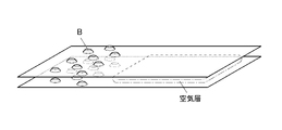
- FIG. 2 is a schematic view showing a state of deflection of the film roll after a lapse of a certain period of time.
- the film roll whose ends were knurled as shown in FIG. 1A was optically knurled.
- the end portion protrudes as shown in FIG. 1C, so that the roll diameter at the end portion is compared with the roll diameter at the center portion.
- FIG. 3 shows a schematic view showing the core side of the film roll of FIG. 2 on the film roll after a lapse of a certain period of time.
- the air in the air layer air layer
- the surface on the core side the surface on the core side
- several sticking parts sticking failure; part D in FIG. 3
- the length is added to the fine wrinkles (wrinkles) of the width as shown in FIG. Sticking in the width direction with a period (gradual failure; see part C in FIG. 3) occurs.
- the air layer (air layer) is appropriately taken into the film roll on which the single-layer optical film is wound, and the end portion is not subjected to nerling processing, and the entire contact surface where the optical films face each other is not applied.
- the problem was solved with the idea of reversing the conventional technique of dispersing the unwinding function by causing moderate and minute contact (at a level where sticking is not recognized).
- the average maximum height difference (PV) ave1 of the film thickness measured within the range of 1000 mm in diameter around an arbitrary point in the optical film is 0.15 to 0.
- This means is characterized in that it is 40 ⁇ m and the value (Dc / De) of the ratio of the outer diameter Dc of the central portion to the outer diameter De of the end portion of the film roll is 0.98 to 1.02.
- the film roll of the present invention is not subjected to the knurling process at the end portion, and the average maximum height difference of the film thickness of the entire surface of the film roll, that is, the film thickness difference is small. Therefore, the air layer (air layer) between the optical films becomes uniform, and the upper side of the film roll becomes flat. Although the lower side of the film roll is also affected by its own weight, the lower side can be suppressed by eliminating the upper side bending in the width direction.
- the stress in the circumferential direction (longitudinal direction) of the film roll becomes uniform, and in the width direction, the optical films stick to each other due to contact with each other centering on the convex portions of the optical films. Stress concentration due to is suppressed.
- the air layer (air layer) taken in at the time of winding does not suppress the contact of the entire width in the product part, but the edge of the optical film is not knurled.
- the unwinding function is also dispersed by controlling the average maximum height difference (PV) ave2 of the film thickness in the diagonal direction with respect to the width direction of the optical film in a specific range in consideration of the variation in the longitudinal direction. It is presumed that it was possible to provide a film roll that can maintain the quality with few winding failures during transportation and long-term storage. In addition, it is presumed that it was possible to provide a method for producing the film roll, which has a high production yield and a significantly reduced inspection load.
- the average maximum height difference (PV) ave2 of the film thickness in the diagonal direction with respect to the width direction of the optical film is less than 0.15, the sticking is recognized immediately after winding. If it is 0.40 or more, minute sticking due to variation occurs and the problem cannot be solved.
- FIG. 1A Schematic diagram of a film roll with knurled edges immediately after winding (immediately after manufacturing) An enlarged view of a part A of the end portion of the film roll in FIG. 1A.
- FIG. 1B is an enlarged cross-sectional view of the film of a part B of the uneven shape of the knurling process.
- Schematic diagram showing the state of deflection of a film roll after a certain period of time Schematic diagram showing how stress is applied to the surface on the core side of the film roll after a certain period of time has passed.
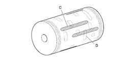
- Schematic of the film roll of the present invention Flow chart showing the flow of the manufacturing process of the solution casting film forming method
- Schematic diagram of an apparatus for manufacturing an optical film by a solution casting film forming method Top view schematically showing the internal configuration of the tenter stretching device Side view of three zones in the tenter stretching device Top view of the three zones in the tenter stretching device
- Schematic diagram of nozzle and heater installation parts when the three zones in the tenter stretching device are viewed from the front Schematic diagram showing the process of winding an optical film and the cross section of the film roll of the present invention after being wound.
- Flow chart showing the flow of the manufacturing process of the melt casting film forming method Schematic configuration diagram of an apparatus for manufacturing an optical film by the melt casting film forming method
- the film roll of the present invention is a film roll in which a single-layer optical film is wound, and has an average maximum height difference (P) of film thickness within a range of 1000 mm in diameter centered on an arbitrary point in the optical film.
- -V) ave1 is 0.15 to 0.40 ⁇ m, and the ratio of the central portion to the end portion (outer diameter of the central portion / outer diameter of the end portion) of the film roll is 0.98 to 1.02. It is characterized by that.
- the film roll of the present invention has a CIE1976L * a * b * a * value and b specified by the color system obtained from the reflectance of the surfaces of the central portion and the end portion of the film roll. * The value satisfies the above equation (1).
- the average maximum height difference (PV) ave2 of the film thickness measured in the order of steps 1 to 3 diagonally with respect to the width direction of the optical film is 0.15. It is preferably about 0.40 ⁇ m from the viewpoint of exhibiting the effect of the present invention.
- the average differential orientation angle ⁇ ave ° and the average differential film thickness d ave ⁇ m within the range of 1000 mm in diameter are calculated around an arbitrary point in the optical film, the average differential orientation angle ⁇ ave ° and the average differential film thickness are calculated. It is preferable that d ave ⁇ m satisfies the above formula (2) from the viewpoint of exhibiting the effect of the present invention.
- the optical film contains inorganic fine particles from the viewpoint of being able to adjust the surface of the optical film to an appropriate uneven state and imparting low birefringence, and from the viewpoint of improving heat resistance and storage stability and environmental stability. ..
- the width of the optical film is preferably 2400 to 3000 mm from the viewpoint of thinning and productivity.
- the length of the optical film is preferably 7500 to 10000 m from the viewpoint of thinning and productivity.
- the method for producing a film roll of the present invention is a method for producing a film roll for producing the film roll, and includes at least a stretching step of stretching an optical film in a stretching furnace and a flattening treatment step, and the flattening.
- the flattening treatment is performed at a temperature as high as 50 to 200 ° C. with respect to the temperature in the stretching furnace, and in the stretching step, the flattening treatment is performed using an infrared (IR) heater.
- IR infrared
- the film roll of the present invention is a film roll in which a single-layer optical film is wound, and has a film thickness within a range of 1000 mm in diameter centered on an arbitrary point in the optical film.
- Average maximum height difference (PV) ave1 is 0.15 to 0.40 ⁇ m, and the ratio of the center to the edge of the film roll (outer diameter of the center / outer diameter of the edge) is 0.98 to It is characterized by being 1.02.
- the "average maximum height difference (PV) ave1 of the film thickness of the optical film” is the maximum height of the peaks and valleys of the uneven shape of the thickness of the optical film measured and observed by the film thickness measurement described later.
- the average value of the differences is used to calculate the height difference between the highest part of the convex structure and the lowest part of the concave structure of the optical film by measuring the film thickness, and the average value is calculated as (P-).
- the "end” refers to a region within a range of 15 to 30 mm inside from the end of the optical film (roll) in the width direction.
- the "central portion” refers to the region portion of the optical film excluding both ends in the width direction.
- the "outer diameter” refers to the diameter of a circle formed at the outermost circumference of the roll, where the cross section perpendicular to the central axis (core) of the film roll is a circle. Therefore, the "outer diameter of the end portion” means the diameter (average value) of the circular cross section observed in the end region. Further, the “outer diameter of the central portion” means the diameter of the circular cross section observed at the central point of the central portion.
- the outer diameter at a position 30 mm from both ends in the width direction of the film roll was measured with a tape measure and used as the outer diameter of the end portion.
- the outer diameter of the end portion was taken as the average value of the outer diameters of both ends.
- Other methods can also be used to measure the outer diameter of the film roll.
- a laser of a laser displacement meter (LK-G5000 manufactured by Keyence) is placed outside the position 30 mm from both ends in the width direction of the film roll. It is also possible to measure the outer diameter by installing it so as to irradiate the diameter and the center position of the central part.
- the optical film of the present invention has an average maximum height difference (P-) of film thickness measured within a diameter of 1000 mm centered on an arbitrary point in the optical film.
- V) ave1 is 0.15 to 0.40 ⁇ m.
- the value (Dc / De) of the ratio of the outer diameter Dc of the central portion to the outer diameter De of the end portion of the film roll is 0.98 to 1.02.
- the film roll of the present invention is not subjected to the knurling process at the end portion, and the average maximum height difference of the film thickness of the entire surface of the film roll, that is, the film thickness difference is small. Therefore, the air layer (air layer) between the optical films becomes uniform, and the upper side of the film roll becomes flat. Although the lower side of the film roll is also affected by its own weight, the lower side can be suppressed by eliminating the upper side bending in the width direction.
- the stress in the circumferential direction (longitudinal direction) of the film roll becomes uniform, and in the width direction, the optical films stick to each other due to contact with each other centering on the convex portions of the optical films. Stress concentration due to is suppressed.
- the average maximum height difference (PV) ave2 of the film thickness measured in the following steps 1 to 3 diagonally with respect to the width direction of the optical film is 0.15 to 0.40 ⁇ m. It is preferable from the viewpoint of solving the problem according to the present invention by the above-mentioned action mechanism.
- Step 1 After measuring the film thickness at an arbitrary position on the end, measure the film thickness at a position moved 50 mm in the width direction and 620 mm in the longitudinal direction from the arbitrary position for each measurement, and repeat this until the other end. Calculate the maximum height difference in the diagonal direction.
- Step 2 After the completion of the step 1, the same measurement as in the step 1 is performed until the total distance of the moving positions in the longitudinal direction reaches 1000 m, and the maximum height difference in the oblique direction is further calculated.
- Step 3 From the maximum height difference in each oblique direction obtained from steps 1 and 2, the average maximum height difference (PV) ave2 of the film thickness in the diagonal direction is calculated.
- the average differential orientation angle ⁇ ave ° and the average differential film thickness d ave ⁇ m within the range of 1000 mm in diameter are calculated around an arbitrary point in the optical film, the average differential orientation angle ⁇ ave ° and the average differential film thickness are calculated. It is preferable that d ave ⁇ m satisfies the following formula (2) from the viewpoint of exhibiting the effect. Equation (2): 800 ⁇
- the "average differential orientation angle ⁇ ave" means a value obtained by measuring and calculating by the following method. That is, the value of the orientation angle at a position moved 5 mm in the width direction and 5 mm in the longitudinal direction from an arbitrary position at one end within a range of 1000 mm in diameter with an arbitrary point in the optical film as the center is measured. And it was measured repeatedly up to the other end. Next, the average value of the absolute values obtained by taking the difference between the values of the adjacent orientation angles was calculated and used as the average difference orientation angle ⁇ ave °. The timing of measurement was set at room temperature immediately before the winding step in both the solution casting film forming method and the melt casting film forming method.
- the “average differential film thickness dave” means a value obtained by measuring and calculating by the following method. That is, the value of the film thickness at a position moved 5 mm in the width direction and 5 mm in the longitudinal direction from an arbitrary position at one end within a range of 1000 mm in diameter with an arbitrary point in the optical film as the center is measured. And it was measured repeatedly up to the other end. Next, the average value of the absolute values obtained by taking the difference between the values of the adjacent film thicknesses was calculated and used as the average difference film thickness dave ⁇ m. The timing of measurement was set at room temperature immediately before the winding step in both the solution casting film forming method and the melt casting film forming method.
- the average maximum height difference (PV) ave1 of the film thickness has a slight height difference of 0.15 to 0.40 in the longitudinal direction, and
- having a large value to some extent as described above defines that the film is an optical film having a minute stress relaxation portion and a non-stress relaxation portion in adjacent regions. Therefore, it is presumed that the non-stress relaxation portion suppresses the local sticking by performing the local relaxation at the time of the local sticking due to the characteristics of the optical film.
- the optical film contains inorganic fine particles from the viewpoint of imparting low birefringence, and it is preferable from the viewpoint of improving heat resistance and storage stability and environmental stability.
- the width of the optical film is in the range of 2400 to 3000 mm from the viewpoint of thinning and productivity.
- the length of the film roll is in the range of 7500 to 10000 m from the viewpoint of thinning and productivity.
- Equation (1) -1.0 ⁇ (end a * -center a * ) + (end b * -center b * ) ⁇ 1.0
- a * value is a coordinate value indicating the hue and saturation in the color system and the position of the red-green transition line.
- the b * value is the coordinate value in the color system. It is a coordinate value that indicates the hue and saturation of, and indicates the position of the yellow-blue transition line.
- the a * value and the b * value can be measured using a colorimeter.
- a colorimeter For example, it can be measured by a pallet cube (Palette CUBE; manufactured by Palette Pty Ltd).
- thermoplastic resin material used for the optical film according to the present invention is not limited as long as it can be handled as a film roll after film formation.
- thermoplastic resins used for polarizing plates include cellulose ester-based resins such as triacetyl cellulose (TAC), cellulose acetate propionate (CAP), and diacetyl cellulose (DAC), and cycloolefin polymers (cycloolefin-based).
- Cyclic olefin resin such as resin (COP) (hereinafter, also referred to as cycloolefin resin), polypropylene resin such as polypropylene (PP), acrylic resin such as polymethylmethacrylate (PMMA), and polyethylene terefterate.
- a polyester resin such as (PET) can be applied.
- an optical film having a low elastic modulus for example, a resin having an elastic modulus of less than 3.0 GPa
- the above-mentioned optical film having a low elastic modulus is viewed from another viewpoint, if there is a height difference between the longitudinal direction and the longitudinal direction of the optical film, the expansion and contraction of the high part and the expansion and contraction of the low part of the optical film The difference will be large.
- the present invention it is possible to control the average maximum height difference (PV) ave1 of the film thickness in the oblique direction with respect to the width direction of the optical film in a specific range in consideration of the variation in the longitudinal direction.
- it is effective to apply a cycloolefin polymer (cycloolefin resin (COP)) or polymethylmethacrylate (acrylic resin (PMMA)), which is a resin having a low elasticity, to a film roll using the thermoplastic resin.
- cycloolefin-based resin can be used because it is easy to control the stretchability and crystallinity, and it is easy for the adhesive to penetrate and it is possible to secure better adhesion to the polarizer. desirable.
- the optical film may be surface-modified after production.
- the film thickness of the optical film is preferably in the range of 5 to 80 ⁇ m, more preferably in the range of 10 to 65 ⁇ m, and even more preferably in the range of 10 to 45 ⁇ m.
- the film thickness is 5 ⁇ m or more, the rigidity of the film roll is high, and it becomes easy to maintain the roll shape. If the film thickness is 80 ⁇ m or less, the mass does not increase too much, and it becomes easy to produce a long film roll.
- the cycloolefin-based resin contained in the film roll of the present invention is a polymer of a cycloolefin monomer, or a copolymer of a cycloolefin monomer and other copolymers. It is preferably a copolymer with the body.
- the cycloolefin monomer is preferably a cycloolefin monomer having a norbornene skeleton, and is a cycloolefin monomer having a structure represented by the following general formula (A-1) or (A-2). More preferably.
- R 1 to R 4 independently represent a hydrogen atom, a hydrocarbon group having 1 to 30 carbon atoms, or a polar group.
- p represents an integer of 0 to 2. However, all of R 1 to R 4 do not represent hydrogen atoms at the same time, R 1 and R 2 do not represent hydrogen atoms at the same time, and R 3 and R 4 do not represent hydrogen atoms at the same time. do.
- hydrocarbon group having 1 to 30 carbon atoms represented by R 1 to R 4 in the general formula (A-1) for example, a hydrocarbon group having 1 to 10 carbon atoms is preferable, and the hydrocarbon group has 1 to 10 carbon atoms. It is more preferably 1 to 5 hydrocarbon groups.
- the hydrocarbon group having 1 to 30 carbon atoms may further have a linking group containing, for example, a halogen atom, an oxygen atom, a nitrogen atom, a sulfur atom or a silicon atom.
- linking groups include divalent polar groups such as carbonyl groups, imino groups, ether bonds, silyl ether bonds, thioether bonds and the like.
- the hydrocarbon group having 1 to 30 carbon atoms include a methyl group, an ethyl group, a propyl group, a butyl group and the like.
- Examples of the polar groups represented by R 1 to R 4 in the general formula (A-1) include a carboxy group, a hydroxy group, an alkoxy group, an alkoxycarbonyl group, an aryloxycarbonyl group, an amino group, an amide group and a cyano group. Is included. Of these, a carboxy group, a hydroxy group, an alkoxycarbonyl group and an aryloxycarbonyl group are preferable, and an alkoxycarbonyl group and an aryloxycarbonyl group are preferable from the viewpoint of ensuring solubility during solution film formation.
- P in the general formula (A-1) is preferably 1 or 2 from the viewpoint of increasing the heat resistance of the optical film. This is because when p is 1 or 2, the obtained polymer becomes bulky and the glass transition temperature tends to be improved.
- R 5 represents an alkylsilyl group having a hydrogen atom, a hydrocarbon group having 1 to 5 carbon atoms, or an alkyl group having 1 to 5 carbon atoms.
- R 6 represents a carboxy group, a hydroxy group, an alkoxycarbonyl group, an aryloxycarbonyl group, an amino group, an amide group, a cyano group, or a halogen atom (fluorine atom, chlorine atom, bromine atom or iodine atom).
- p represents an integer of 0 to 2.
- R 5 in the general formula (A-2) preferably represents a hydrocarbon group having 1 to 5 carbon atoms, and more preferably represents a hydrocarbon group having 1 to 3 carbon atoms.
- R 6 in the general formula (A-2) preferably represents a carboxy group, a hydroxy group, an alkoxycarbonyl group and an aryloxycarbonyl group, and from the viewpoint of ensuring solubility during solution film formation, the alkoxycarbonyl group and aryl Oxycarbonyl groups are more preferred.
- P in the general formula (A-2) preferably represents 1 or 2 from the viewpoint of increasing the heat resistance of the optical film. This is because when p represents 1 or 2, the obtained polymer becomes bulky and the glass transition temperature tends to improve.
- a cycloolefin monomer having a structure represented by the general formula (A-2) is preferable from the viewpoint of improving the solubility in an organic solvent.
- an organic compound loses its symmetry and thus its crystallinity is lowered, so that its solubility in an organic solvent is improved.
- R 5 and R 6 in the general formula (A-2) are substituted with only the ring-constituting carbon atom on one side with respect to the axis of symmetry of the molecule, the symmetry of the molecule is low, that is, the general formula (A-). Since the cycloolefin monomer having the structure represented by 2) has high solubility, it is suitable for producing an optical film by a solution casting method.
- the content ratio of the cycloolefin monomer having the structure represented by the general formula (A-2) in the polymer of the cycloolefin monomer is the total of all the cycloolefin monomers constituting the cycloolefin resin. For example, it can be 70 mol% or more, preferably 80 mol% or more, and more preferably 100 mol%.
- a cycloolefin monomer having a structure represented by the general formula (A-2) is contained in a certain amount or more, the orientation of the resin is increased, so that the retardation value is likely to increase.
- ring-opening copolymerizable copolymerizable monomers examples include cycloolefins such as cyclobutene, cyclopentene, cycloheptene, cyclooctene and dicyclopentadiene.
- copolymerizable monomers examples include unsaturated double bond-containing compounds, vinyl-based cyclic hydrocarbon monomers, (meth) acrylates, and the like.
- unsaturated double bond-containing compounds include olefin compounds having 2 to 12 (preferably 2 to 8) carbon atoms, and examples thereof include ethylene, propylene and butene.
- vinyl-based cyclic hydrocarbon monomers examples include vinyl cyclopentene-based monomers such as 4-vinylcyclopentene and 2-methyl-4-isopropenylcyclopentene.
- Examples of (meth) acrylates include alkyl (meth) acrylates having 1 to 20 carbon atoms such as methyl (meth) acrylate, 2-ethylhexyl (meth) acrylate and cyclohexyl (meth) acrylate.
- the content ratio of the cycloolefin monomer in the copolymer of the cycloolefin monomer and the copolymerizable monomer is, for example, 20 to 80 mol% with respect to the total of all the monomers constituting the copolymer. It can be within the range, preferably within the range of 30 to 70 mol%.
- the cycloolefin-based resin is obtained by polymerizing a cycloolefin monomer having a norbornene skeleton, preferably a cycloolefin monomer having a structure represented by the general formula (A-1) or (A-2). It is a polymer obtained by copolymerization, and examples thereof include the following polymers (1) to (7).
- Ring-opening polymer of cycloolefin monomer (2) Ring-opening copolymer of cycloolefin monomer and copolymerizable monomer that can be ring-opened and copolymerized (3)
- the above (1) Alternatively, a hydrogenated product of the ring-opened (co) polymer of (2) (4) The ring-opened (co) polymer of (1) or (2) above was cyclized by the Friedelcrafts reaction, and then hydrogen was added.
- the polymers of (1) to (7) above can be obtained by known methods, for example, the methods described in JP-A-2008-107534 and JP-A-2005-227606.
- the catalyst and solvent used for the ring-opening copolymerization of (2) above those described in paragraphs 0019 to 0024 of JP-A-2008-107534 can be used.
- the catalyst used for the hydrogenated additives of (3) and (6) above for example, those described in paragraphs 0025 to 0028 of JP-A-2008-107534 can be used.
- the acidic compound used in the Friedel-Crafts reaction of (4) above for example, those described in paragraph 0029 of JP-A-2008-107534 can be used.
- the catalyst used for the addition polymerization of the above (5) to (7) for example, those described in paragraphs 0058 to 0063 of JP-A-2005-227606 can be used.
- the alternating copolymerization reaction of (7) above can be carried out, for example, by the method described in paragraphs 0071 and 0072 of JP-A-2005-227606.
- the polymers of the above (1) to (3) and (5) are preferable, and the polymers of the above (3) and (5) are more preferable.
- the cycloolefin-based resin has a structural unit represented by the following general formula (B-1) in that the glass transition temperature of the obtained cycloolefin-based resin can be raised and the light transmittance can be raised. It is preferable that at least one of the structural units represented by the following general formula (B-2) is included, and only the structural unit represented by the general formula (B-2) is included, or the general formula (B-1) is used. It is more preferable to include both the structural unit represented and the structural unit represented by the general formula (B-2).
- the structural unit represented by the general formula (B-1) is a structural unit derived from the cycloolefin monomer represented by the above-mentioned general formula (A-1), and is represented by the general formula (B-2).
- the structural unit is a structural unit derived from the cycloolefin monomer represented by the above-mentioned general formula (A-2).
- R 1 to R 4 and p are synonymous with R 1 to R 4 and p of the general formula (A-1), respectively.
- R5 to R6 and p are synonymous with R5 to R6 and p of the general formula ( A - 2 ), respectively.
- the cycloolefin-based resin according to the present invention may be a commercially available product.
- Examples of commercially available cycloolefin resins include Arton G (eg, G7810, etc.), Arton F, Arton R (eg, R4500, R4900, R5000, etc.), and Arton RX, manufactured by JSR Corporation. ..
- the intrinsic viscosity [ ⁇ ] inh of the cycloolefin resin is preferably in the range of 0.2 to 5 cm 3 / g, and preferably in the range of 0.3 to 3 cm 3 / g when measured at 30 ° C. Is more preferable, and more preferably in the range of 0.4 to 1.5 cm 3 / g.
- the number average molecular weight (Mn) of the cycloolefin resin is preferably in the range of 8000 to 100,000, more preferably in the range of 10,000 to 80,000, and further preferably in the range of 12,000 to 50,000. ..
- the weight average molecular weight (Mw) of the cycloolefin resin is preferably in the range of 20,000 to 300,000, more preferably in the range of 30,000 to 250,000, and further preferably in the range of 40,000 to 200,000. ..
- the number average molecular weight and weight average molecular weight of the cycloolefin resin can be measured by gel permeation chromatography (GPC) in terms of polystyrene.
- the number average molecular weight and the weight average molecular weight are within the above ranges, the heat resistance, water resistance, chemical resistance, mechanical properties, and molding processability as a film of the cycloolefin resin are good. Become.
- the glass transition temperature (Tg) of the cycloolefin resin is usually 110 ° C. or higher, preferably in the range of 110 to 350 ° C., more preferably in the range of 120 to 250 ° C., and 120 to 120 ° C. It is more preferably in the range of 220 ° C.
- the glass transition temperature (Tg) is 110 ° C. or higher, deformation under high temperature conditions can be easily suppressed.
- the glass transition temperature (Tg) is 350 ° C. or lower, the molding process is facilitated, and deterioration of the resin due to heat during the molding process is also easily suppressed.
- the content of the cycloolefin resin is preferably 70% by mass or more, more preferably 80% by mass or more with respect to the film.
- the acrylic resin according to the present invention is a polymer of an acrylic acid ester or a methacrylic acid ester, and also includes a copolymer with another monomer. Therefore, the acrylic resin according to the present invention also includes a methacrylic resin.
- the resin is not particularly limited, but the methyl methacrylate unit is in the range of 50 to 99% by mass, and other monomer units copolymerizable therewith are in the range of 1 to 50% by mass. Is preferable.
- Hydroxyalkyl acrylates such as hydroxyethyl acrylates, ⁇ , ⁇ -unsaturated acids such as acrylic acid and methacrylic acid, acrylamides such as acryloylmorpholine and N-hydroxyphenylmethacrylate, N-vinylpyrrolidone, maleic acid, fumaric acid, itaconic acid and the like.
- Unsaturated group-containing divalent carboxylic acid aromatic vinyl compounds such as styrene and ⁇ -methylstyrene, ⁇ , ⁇ -unsaturated nitriles such as acrylonitrile and methacrylic nitrile, maleic anhydride, maleimide, N-substituted maleimide, and glutal. Examples thereof include imide and glutaric acid anhydride.
- Examples of copolymerizable monomers that form units excluding glutarimide and glutaric anhydride from the above units include monomers corresponding to the above units.
- alkyl methacrylate having 2 to 18 carbon atoms of alkyl number alkyl acrylate having 1 to 18 carbon atoms of alkyl number
- hydroxyalkyl acrylate such as isobornyl methacrylate and 2-hydroxyethyl acrylate
- acrylic acid methacrylic acid and the like.
- Unsaturated group-containing divalent carboxylic acids such as ⁇ , ⁇ -unsaturated acid, acryloylmorpholine, acrylamide such as N-hydroxyphenylmethacrylate, N-vinylpyrrolidone, maleic acid, fumaric acid, and itaconic acid, styrene, ⁇ -methylstyrene.
- aromatic vinyl compounds such as, acrylonitrile, ⁇ , ⁇ -unsaturated nitriles such as methacrylonitrile, maleic anhydride, maleimide and N-substituted maleimide, and the like.
- the glutarimide unit can be formed, for example, by reacting an intermediate polymer having a (meth) acrylic acid ester unit with a primary amine (imidizing agent) to imidize it (see JP-A-2011-26563). ).
- the glutaric acid anhydride unit can be formed, for example, by heating an intermediate polymer having a (meth) acrylic acid ester unit (see Japanese Patent No. 4961164).
- the acrylic resin according to the present invention contains isobornyl methacrylate, acryloylmorpholine, N-hydroxyphenylmethacrylicamide, N-vinylpyrrolidone, styrene, hydroxyethylmethacrylate, and anhydride from the viewpoint of mechanical strength. It is particularly preferred that maleic acid, maleimide, N-substituted maleimide, glutaric anhydride or glutarimide are included.
- the acrylic resin according to the present invention has the viewpoint of controlling dimensional changes with respect to changes in the temperature and humidity atmosphere of the environment, peelability from a metal support during film production, drying properties of an organic solvent, heat resistance and mechanical strength.
- the weight average molecular weight (Mw) is preferably in the range of 50,000 to 1,000,000, more preferably in the range of 100,000 to 1,000,000, and particularly preferably in the range of 200,000 to 800,000.
- the heat resistance and mechanical strength are excellent, and if it is 1,000,000 or less, the peelability from the metal support and the drying property of the organic solvent are excellent.
- the method for producing the acrylic resin according to the present invention is not particularly limited, and any known method such as suspension polymerization, emulsion polymerization, bulk polymerization, or solution polymerization may be used.
- polymerization initiator ordinary peroxide-based and azo-based ones can be used, and redox-based ones can also be used.
- the polymerization temperature can be carried out within the range of 30 to 100 ° C. for suspension or emulsion polymerization, and within the range of 80 to 160 ° C. for massive or solution polymerization.
- polymerization can also be carried out using an alkyl mercaptan or the like as a chain transfer agent.
- the glass transition temperature (Tg) of the acrylic resin is preferably in the range of 80 to 120 ° C. from the viewpoint of maintaining the mechanical strength of the film.
- acrylic resin according to the present invention commercially available ones can also be used.
- Delpet 60N, 80N, 980N, SR8200 all manufactured by Asahi Kasei Chemicals Co., Ltd.
- Two or more kinds of acrylic resins can be used in combination.
- the acrylic resin according to the present invention preferably contains an additive, and as an example of the additive, the acrylic particles (rubber elastic particles) described in International Publication No. 2010/001668 are used as the mechanical strength of the film. It is preferably contained for improvement and adjustment of the dimensional change rate.
- Examples of commercially available products of such a multilayer structure acrylic granular composite are, for example, "Metabrene W-341” manufactured by Mitsubishi Rayon, “Kaneka” manufactured by Kaneka, “Paraloid” manufactured by Kureha, and Roam and Hearth.
- Examples include “Acryloid” manufactured by Aica, “Staphyroid” manufactured by Aica, Chemisnow MR-2G, MS-300X (above, manufactured by Soken Chemical Co., Ltd.) and "Parapet SA” manufactured by Kuraray. , Alone or two or more can be used.
- the volume average particle diameter of the acrylic particles is 0.35 ⁇ m or less, preferably in the range of 0.01 to 0.35 ⁇ m, and more preferably in the range of 0.05 to 0.30 ⁇ m.
- the particle size is above a certain level, the film can be easily stretched under heating, and when the particle size is below a certain level, the transparency of the obtained film is not easily impaired.
- the optical film of the present invention preferably has a flexural modulus (JIS K7171) of 10.5 GPa or less.
- This flexural modulus is more preferably 1.3 GPa or less, still more preferably 1.2 GPa or less.
- This flexural modulus varies depending on the type and amount of acrylic resin and rubber elastic particles in the film. For example, the larger the content of rubber elastic particles, the smaller the flexural modulus.
- the flexural modulus is generally smaller when a copolymer of alkyl methacrylate and alkyl acrylate or the like is used than when a homopolymer of alkyl methacrylate is used.
- the cellulose ester used in the present invention is a part or all of the hydrogen atoms of the hydroxy groups (-OH) at the 2-position, 3-position and 6-position in the ⁇ -1,4-bonded glucose unit constituting the cellulose.
- a cellulose acylate resin substituted with an acyl group Refers to a cellulose acylate resin substituted with an acyl group.
- the cellulose ester used is not particularly limited, but is preferably a linear or branched carboxylic acid ester having about 2 to 22 carbon atoms.
- the carboxylic acid constituting the ester may be an aliphatic carboxylic acid, may form a ring, or may be an aromatic carboxylic acid.
- the hydrogen atom of the hydroxy group portion of cellulose is an acyl group having 2 to 22 carbon atoms such as an acetyl group, a propionyl group, a butyryl group, an isobutyryl group, a valeryl group, a pivaloyl group, a hexanoyl group, an octanoyl group, a lauroyl group and a stearoyl group.
- Substituted cellulose esters can be mentioned.
- the carboxylic acid (acyl group) constituting the ester may have a substituent.
- the carboxylic acid constituting the ester is particularly preferably a lower fatty acid having 6 or less carbon atoms, and more preferably a lower fatty acid having 3 or less carbon atoms.
- the acyl group in the cellulose ester may be a single type or a combination of a plurality of acyl groups.
- preferable cellulose esters include cellulose acetates such as diacetyl cellulose (DAC) and triacetyl cellulose (TAC), as well as cellulose acetate propionate (CAP), cellulose acetate butyrate, and cellulose acetate propionate butyrate.
- DAC diacetyl cellulose
- TAC triacetyl cellulose
- CAP cellulose acetate propionate
- cellulose acetate butyrate cellulose acetate butyrate
- cellulose acetate propionate butyrate cellulose acetate propionate butyrate.
- a mixed fatty acid ester of cellulose to which a propionate group or a butyrate group is bonded can be mentioned.
- These cellulose esters may be used alone or in combination of two or more.
- the Rt humidity fluctuation which is the retardation (phase difference) in the thickness direction, is caused by the coordination of water molecules to the carbonyl group of cellulose, so that the degree of substitution of the acyl group is high, that is, the carbonyl group in the cellulose has a high degree of substitution. The larger the amount, the worse the Rt humidity fluctuation tends to be.
- the total degree of substitution of the cellulose ester is preferably in the range of 2.1 to 2.5. Within this range, environmental fluctuations (particularly Rt fluctuations due to humidity) can be suppressed and the uniformity of the film thickness can be improved. More preferably, it is in the range of 2.2 to 2.45 from the viewpoint of improving the ductility and stretchability during film formation and further improving the uniformity of the film thickness.
- the cellulose ester satisfies both the following formulas (a) and (b).
- X is the degree of substitution of an acetyl group
- Y is the degree of substitution of a propionyl group or a butyryl group, or a mixture thereof.
- CAP cellulose acetate propionate
- Cellulose acetate which is particularly preferably used, has 2.1 ⁇ X ⁇ 2.5 (more preferably 2.15 ⁇ X ⁇ 2.45) from the viewpoint of setting the desired range of phase difference expression, Rt humidity fluctuation, and film thickness variation. ) Cellulose diacetate (DAC).
- DAC Cellulose diacetate
- the cellulose acetate propionate (CAP) that is particularly preferably used is 0.95 ⁇ X ⁇ 2.25, 0.1 ⁇ Y ⁇ 1.2, 2.15 ⁇ X + Y ⁇ . It is 2.45.
- the degree of substitution of the acyl group indicates the average number of acyl groups per glucose unit, and how many hydrogen atoms of the hydroxy groups at the 2, 3, and 6 positions of the 1 glucose unit are substituted with the acyl group. Is shown. Therefore, the maximum degree of substitution is 3.0, which means that all the hydrogen atoms of the hydroxy groups at the 2-position, 3-position and 6-position are substituted with acyl groups. These acyl groups may be substituted at the 2-position, 3-position, and 6-position of the glucose unit on average, or may be substituted with a distribution. The degree of substitution is determined by the method specified in ASTM-D817-96.
- Cellulose acetates having different degrees of substitution may be mixed and used in order to obtain desired optical properties.
- the mixing ratio of different cellulose acetates is not particularly limited.
- the number average molecular weight (Mn) of the cellulose ester is in the range of 2 ⁇ 10 4 to 3 ⁇ 105, further in the range of 2 ⁇ 10 4 to 1.2 ⁇ 105, and further in the range of 4 ⁇ 10 4 to 4 .
- the range of 8 ⁇ 10 4 is preferable from the viewpoint of increasing the mechanical strength of the obtained film roll.
- the number average molecular weight Mn of the cellulose ester is calculated by measurement using gel permeation chromatography (GPC) under the above-mentioned measurement conditions.
- the weight average molecular weight (Mw) of the cellulose ester is in the range of 2 ⁇ 10 4 to 1 ⁇ 10 6 , further in the range of 2 ⁇ 10 4 to 1.2 ⁇ 105, and further in the range of 4 ⁇ 10 4 to 4 .
- the range of 8 ⁇ 10 4 is preferable from the viewpoint of increasing the mechanical strength of the obtained film roll.
- the raw material cellulose of the cellulose ester is not particularly limited, and examples thereof include cotton linter, wood pulp, and kenaf.
- the cellulose esters obtained from them can be mixed and used in any ratio.
- Cellulose esters such as cellulose acetate and cellulose acetate propionate can be produced by known methods.
- cellulose as a raw material is mixed with a predetermined organic acid (acetic acid, propionic acid, etc.), an acid anhydride (acetic acid anhydride, propionic anhydride, etc.), and a catalyst (sulfuric acid, etc.) to esterify the cellulose and carry out cellulose. Proceed with the reaction until the triester is formed.
- a predetermined organic acid acetic acid, propionic acid, etc.
- an acid anhydride acetic acid anhydride, propionic anhydride, etc.
- a catalyst sulfuric acid, etc.
- the three hydroxy groups of the glucose unit are replaced with the acyl acid of the organic acid.
- the cellulose ester is hydrolyzed to synthesize a cellulose ester resin having a desired degree of acyl substitution.
- the cellulose ester resin is completed through steps such as filtration, precipitation, washing with water, dehydration, and drying. Specifically, it can be synthesized with reference to the method described in JP-A No. 10-45804.
- the film roll of the present invention may contain the following as other additives in addition to the above-mentioned thermoplastic resin.
- the film roll of the present invention preferably contains at least one type of plasticizer for the purpose of imparting processability to, for example, a polarizing plate protective film. It is preferable to use the plasticizer alone or in combination of two or more.
- plasticizers containing at least one plasticizer selected from the group consisting of sugar esters, polyesters, and styrene-based compounds effectively controls the moisture permeability and is compatible with the base resin such as cellulose esters. It is preferable from the viewpoint that the solubility can be highly compatible.
- the plasticizer has a molecular weight of 15,000 or less, more preferably 10,000 or less, from the viewpoint of achieving both improvement in moisture and heat resistance and compatibility with a base resin such as a cellulose ester.
- the weight average molecular weight (Mw) is preferably 10,000 or less.
- the preferred weight average molecular weight (Mw) range is in the range of 100 to 10000, more preferably in the range of 400 to 8000.
- the compound having a molecular weight of 1500 or less is preferably contained in the range of 6 to 40 parts by mass with respect to 100 parts by mass of the base resin, and is preferably 10 to 20 parts by mass. It is more preferable to contain it within the range. By containing it within the above range, it is possible to achieve both effective control of moisture permeability and compatibility with the base resin, which is preferable.
- the film roll of the present invention may contain a sugar ester compound for the purpose of preventing hydrolysis.
- a sugar ester compound for the purpose of preventing hydrolysis.
- a sugar ester compound having at least one or more and 12 or less pyranose structures or at least one furanose structure and esterifying all or part of the OH groups having that structure can be used. can.
- the film roll of the present invention may also contain polyester.
- the polyester is not particularly limited, but for example, a polymer (polyester polyol) having a hydroxy group at the end, which can be obtained by a condensation reaction between a dicarboxylic acid or an ester-forming derivative thereof and glycol, or a hydroxy at the end of the polyester polyol.
- a polymer whose group is sealed with a monocarboxylic acid (end-sealed polyester) can be used.
- the ester-forming derivative referred to here is an esterified product of a dicarboxylic acid, a dicarboxylic acid chloride, or an anhydride of a dicarboxylic acid.
- a styrene-based compound may be used for the film roll of the present invention for the purpose of improving the water resistance of the optical film.
- the styrene-based compound may be a homopolymer of a styrene-based monomer, or may be a copolymer of a styrene-based monomer and another copolymerization monomer.
- the content ratio of the structural unit derived from the styrene-based monomer in the styrene-based compound is preferably in the range of 30 to 100 mol%, more preferably 50 to 100 mol% in order for the molecular structure to have a certain bulkiness or more. It can be within the range.
- styrene-based monomers examples include styrene; alkyl-substituted styrenes such as ⁇ -methylstyrene, ⁇ -methylstyrene, and p-methylstyrene; halogen-substituted styrenes such as 4-chlorostyrene and 4-bromostyrene; p-hydroxy.
- Hydroxystyrenes such as styrene, ⁇ -methyl-p-hydroxystyrene, 2-methyl-4-hydroxystyrene, 3,4-dihydroxystyrene; vinylbenzyl alcohols; p-methoxystyrene, p-tert-butoxystyrene, m -Alkoxy-substituted styrenes such as tert-butoxystyrene; vinyl benzoic acids such as 3-vinylbenzoic acid and 4-vinylbenzoic acid; 4-vinylbenzylacetrene;4-acetoxystyrene;2-butylamide styrene, 4-methylamide Amid styrenes such as styrene and p-sulfonamide styrene; aminostyrenes such as 3-aminostyrene, 4-aminostyrene, 2-isopropenylaniline and vinylbenzyldi
- Nitrostyrenes such as 3-cyanostyrene and 4-cyanostyrene; vinylphenylacetrene; arylstyrenes such as phenylstyrene, indens and the like are included.
- the styrene-based monomer may be one type or a combination of two or more types.
- the film roll of the present invention contains other optional components such as antioxidants, colorants, ultraviolet absorbers, matting agents, acrylic particles, hydrogen-bonding solvents and ionic surfactants.
- optional components such as antioxidants, colorants, ultraviolet absorbers, matting agents, acrylic particles, hydrogen-bonding solvents and ionic surfactants.
- antioxidants As the film roll of the present invention, commonly known antioxidants can be used.
- lactone-based, sulfur-based, phenol-based, double-bonded, hindered amine-based, and phosphorus-based compounds can be preferably used.
- antioxidants and the like are added in the range of 0.05 to 20% by mass, preferably in the range of 0.1 to 1% by mass, with respect to the resin which is the main raw material of the optical film.
- These antioxidants and the like can obtain a synergistic effect by using several kinds of compounds of different systems in combination rather than using only one kind. For example, the combined use of lactone-based, phosphorus-based, phenol-based and double-bonding compounds is preferable.
- the film roll of the present invention preferably contains a colorant for color tone adjustment within a range that does not impair the effects of the present invention.
- the colorant means a dye or a pigment, and in the present invention, it means a colorant having the effect of making the color tone of the liquid crystal screen blue, the adjustment of the yellow index, and the reduction of haze.
- dyes and pigments can be used as colorants, but anthraquinone dyes, azo dyes, phthalocyanine pigments, etc. are effective.
- UV absorber Since the film roll of the present invention can also be used on the visible side or the backlight side of the polarizing plate, it may contain an ultraviolet absorber for the purpose of imparting an ultraviolet absorbing function.
- the ultraviolet absorber is not particularly limited, and examples thereof include ultraviolet absorbers such as benzotriazole-based, 2-hydroxybenzophenone-based, and salicylic acid phenyl ester-based.
- ultraviolet absorbers such as benzotriazole-based, 2-hydroxybenzophenone-based, and salicylic acid phenyl ester-based.
- Benzophenones can be exemplified.
- the above-mentioned ultraviolet absorber may be used alone or in combination of
- the amount of the ultraviolet absorber used is not uniform depending on the type of the ultraviolet absorber, the conditions of use, etc., but is generally in the range of 0.05 to 10% by mass, preferably 0.1, based on the base resin. It is added in the range of ⁇ 5% by mass.
- Fine particles For the film roll of the present invention, it is preferable to add fine particles that impart slipperiness to the film roll. In particular, it is effective to add fine particles from the viewpoint of improving the slipperiness of the surface of the optical film according to the present invention, improving the slipperiness at the time of winding, and preventing the occurrence of scratches and blocking.
- the fine particles may be either inorganic fine particles or organic fine particles as long as they do not impair the transparency of the obtained film roll and have heat resistance at the time of melting, but inorganic fine particles are more preferable. These fine particles can be used alone or in combination of two or more.
- silicon dioxide having excellent transparency is particularly preferably used because it has a refractive index close to that of the cycloolefin resin, acrylic resin or cellulose ester resin.
- silicon dioxide examples include Aerodil (registered trademark) 200V, Aerodil (registered trademark) R972V, Aerodil (registered trademark) R972, R974, R812, 200, 300, R202, OX50, TT600, NAX50 (above Japan Aerozil Co., Ltd.) , Seahoster (registered trademark) KEP-10, Seahoster (registered trademark) KEP-30, Seahoster (registered trademark) KEP-50 (all manufactured by Nippon Catalyst Co., Ltd.), Silohobic (registered trademark) 100 (Fuji Silicia) Commercial products having trade names such as Nip Seal (registered trademark) E220A (manufactured by Nippon Silica Industry Co., Ltd.) and Admafine (registered trademark) SO (manufactured by Admatex Co., Ltd.) can be preferably used.
- Nip Seal registered trademark
- E220A manufactured by Nippon Silica Industry Co.
- the shape of the particles can be used without particular limitation such as amorphous, needle-shaped, flat, and spherical, but it is particularly preferable to use spherical particles because the transparency of the obtained film roll can be improved.
- the size of the particles is preferably smaller than the wavelength of visible light, and more preferably 1/2 or less of the wavelength of visible light. ..
- the particle size means the size of the agglomerates when the particles are agglomerates of primary particles. When the particles are not spherical, it means the diameter of a circle corresponding to the projected area.
- the fine particles are preferably added in the range of 0.05 to 10% by mass, preferably in the range of 0.1 to 5% by mass, with respect to the base resin.
- the optical film unwound from the film roll of the present invention is suitably used as a protective film for a polarizing plate as an optical film, and is used for various optical measuring devices and display devices such as liquid crystal display devices and organic electroluminescence display devices. Can be done.
- the method for producing a film roll of the present invention includes at least a stretching step of stretching an optical film in a stretching furnace and a flattening treatment step, and in the flattening treatment step, in the stretching furnace. It is characterized in that it is flattened at a high temperature within the range of 50 to 200 ° C. with respect to the temperature.
- the "film roll” as used in the present invention refers to an optical film wound in a roll shape.
- a usual production method such as an inflation method, a T-die method, a calendar method, a cutting method, a casting method, an emulsion method, a hot press method, etc. can be used, but color suppression and foreign matter can be formed.
- the solution casting film forming method and the melt casting film forming method are preferable, and the solution casting film forming method is particularly suitable for obtaining a uniform surface. More preferred.
- Film thickness control means The average maximum height difference (PV) ave1 of the film thickness of the optical film according to the present invention and the outer diameter of the central portion of the film roll.
- PV average maximum height difference
- a means for flattening the uneven shape of the optical film surface can be considered, for example, the following. Examples thereof include flattening treatments 1 to 4. Moreover, you may combine them.
- the film thickness is controlled by a method of controlling the pitch of pump pulsation.
- the dope discharge amount is controlled by increasing the rotation speed according to the gear ratio of the gear pump, the pulsation at the time of dope feeding (extrusion of resin in the case of melting) is controlled, and the pitch of the pump pulsation is controlled.
- the liquid feeding capacity of the pump will be supplementarily described.
- the pulsation will not increase due to the influence of the rotation speed of the pump, and if it is not too long, the pressure loss will be large. Not too much, it is possible to prevent the pump's liquid feeding capacity from dropping beyond the lower limit. Further, if the rotation speed of the pump is not too slow, it is possible to prevent the liquid feeding capacity from being lowered, and if it is not too fast, the pressure loss is not too large and it is possible to prevent the liquid feeding capacity from being lowered.
- the length of the pipe from the pump to the casting die should be within the range of 50 to 100 m, and the gear ratio of the gear pump used for dope feeding (extruding resin in the case of melting) should be adjusted to pump.
- the rotation speed of the above is preferably in the range of 10 to 50 rpm.
- performing the flattening process 1 means that the length of the pipe from the pump to the casting die is 60 m in the casting step described later, and the gear pump used for the dope feed is fed. It means adjusting the gear ratio and setting the rotation speed of the pump to 20 rpm. Further, not performing the flattening process 1 means that in the casting process described later, the length of the pipe from the pump to the casting die is set to 30 m, which is outside the range of 50 to 100 m, and the gear pump used for doping liquid feeding. The gear ratio of the pump is adjusted to 70 rpm, which is outside the range of 10 to 50 rpm.
- the initial discharge film thickness is controlled by the heat bolt of the casting die.
- the casting die is provided with a mechanism for adjusting the slit for discharging the dope (extruding the resin in the case of melting).
- a method of adjusting the gap between the widths of the slits for discharging the dope by using the heat bolt of the casting die to control the initial discharge film thickness of the casting film will be supplementarily described.
- the preparation can be performed relatively easily technically and it does not take much time.
- the gap between the widths of the slits for discharging the dope is too large, the initial discharge film thickness of the cast film cannot be flattened.
- the heat bolt of the casting die is used to reduce the gap between the widths of the slits that discharge the dope and the film thickness deviation immediately after discharge from 1.0 to the entire casting film. It is preferable to adjust the thickness within the range of 5.0% and control the initial discharge film thickness of the cast film.
- performing the flattening process 2 means that in the casting step described later, the heat bolt of the casting die is used to create a gap in the width of the slit for discharging the dope, and the film immediately after the discharge. It means that the thickness deviation is adjusted to 1.5% with respect to the entire casting film to control the initial discharge film thickness of the casting film.
- the width of the slit for discharging the dope is determined by the heat bolt of the casting die, and the film thickness deviation immediately after the ejection is determined as the casting film. It is defined as adjusting the initial discharge film thickness of the cast film to 5.5%, which is outside the range of 1.0 to 5.0% with respect to the whole.
- the film thickness deviation immediately after ejection in the definition of whether or not the flattening process 2 is performed can be appropriately changed depending on the film thickness required for the optical film to be produced.
- (Flatification process 3) Warm air is blown onto the flow film, and the heat flattens the protrusions to control the film thickness.
- Wind may be blown with the surface layer on the opposite side of the casting film forming a film, or warm air may be blown immediately after the casting film is peeled off from the belt. You may.
- the inside of the casting film is soft because it contains a solvent, in order to flatten the protrusions, the non-uniformity in the width direction of the casting film is measured online, and the temperature, wind speed, or air volume of the dry air is measured.
- the film thickness is controlled by adjusting and adjusting the amount of residual solvent.
- the temperature, air velocity or air volume of the dry air, and the residual solvent amount will be supplementarily described. If the temperature of the dry air is not too low, the wind speed is too low, or the air volume is not too small, the film thickness can be appropriately controlled. Also, unless the temperature is too high, the wind speed is too high, or the air volume is too high, the film thickness will not be locally uncontrollable.
- the amount of residual solvent is not too small, it will not occur that the film is not soft and cannot be flattened in a state closer to an optical film than in a cast film state. Further, if it is not too much, the film thickness does not vary when flattened.
- flattening 3 can be performed with a thin film formed on the surface layer by adjusting the amount of residual solvent to an appropriate level.
- the temperature of the dry air is preferably in the range of 10 to 80 ° C.
- the wind speed is preferably in the range of 5 to 40 m / sec.
- the amount of residual solvent is preferably 150 to 550% by mass.
- the film thickness is controlled by adjusting the temperature.
- to carry out the flattening treatment 3 means that the surface layer is coated by drying the casting film on the belt until the residual solvent amount becomes 200% by mass in the casting step described later. It is said that the protrusions are flattened by blowing warm air at a wind speed of 16 m / sec (40 ° C.) after the formation. Further, not performing the flattening treatment 3 means that in the casting step described later, the casting film on the belt is dried until it reaches 5% by mass, which is outside the range of 150 to 550% by mass. After the film is formed on the surface layer, warm air of 45 m / sec (40 ° C.), which is outside the range of wind speed of 5 to 40 m / sec, is blown to flatten the protrusions.
- the film thickness is controlled by changing the temperature inside the furnace in the tenter stretching device and the timing of heat treatment.
- the above heat treatment is performed by an infrared (IR) heater, but the heat treatment may be performed by another method.
- the flattening treatment 4 can be performed in a furnace of another step other than the stretching step by changing the corresponding environmental temperature and the timing of the heat treatment.
- the tenter stretching device is a device that stretches the optical film by grasping both ends of the optical film in the width direction with clips and widening the interval while running the clips together with the optical film, and is usually a plurality of zones (preheating zones).
- the timing of applying heat treatment among the above zones is (1-1) when passing through the preheating zone in the tenter stretching device, and (1-2) passing through the stretching zone. At the time, (1-3) at least one of the three when passing through the heat treatment zone is to be used.
- the inside of the stretching furnace defined in the present application refers to three zones, a preheating zone, a stretching zone and a heat fixing zone, and the temperature inside the stretching furnace is a stretching furnace in which the position 100 mm above the center of the optical film immediately before stretching is measured in the stretching zone. The temperature inside. If the temperature difference between the furnace temperature and the heat treatment is not too small or too large, the flattening process can be easily controlled.
- the temperature difference between the furnace temperature and the heat treatment is preferably in the range of 50 to 200 ° C.
- performing the flattening treatment 4 means that a required number of infrared (IR) heaters are installed and heat-treated in the stretching process described later. Further, not performing the flattening treatment 4 means that the infrared (IR) heater is not installed and the heat treatment is not performed in the stretching process described later.
- IR infrared
- the infrared (IR) heater that can be used in carrying out the present invention is designed so that the infrared irradiation range can be narrowed pinpointly by using a mirror that reflects infrared rays, unlike a general infrared (IR) heater. Is preferable.
- mirrors that reflect infrared rays include cold mirrors (manufactured by Sigma Kouki Co., Ltd.) and aluminum augmentation reflection mirrors for infrared rays (manufactured by Novo Optics Co., Ltd.).
- an aluminum brightening reflection mirror for infrared rays (manufactured by Novo Optics), which is a mirror using aluminum, was used.
- the infrared irradiation range of one current general infrared (IR) heater is, for example, MCHNNNS3, irradiation energy 400 W (manufactured by Misumi Co., Ltd.) and 500 mm in the width direction, whereas it was used in the practice of the present invention.
- the infrared irradiation range of one infrared (IR) heater is 100 to 150 mm in the width direction with an irradiation energy of 550 W (manufactured by Heat Tech Co., Ltd.).
- the flattening process is performed using an infrared (IR) heater, and the average value B of the heat amount A at the center and the heat amount B at the end at a position 100 mm away from the infrared (IR) heater is By satisfying the above formula (3), the flattening process can be effectively realized.
- the temperature distribution of the average value B of the heat quantity A at the center and the heat quantity B at the end at a position 100 mm away from the infrared (IR) heater is measured by a thermo-viewer (VIM-640G2ULC manufactured by Vision Sensing Co., Ltd.). , It was calculated by taking the average value, but when the heat treatment was performed by another method, it corresponded accordingly.
- the optical film is heated by the infrared (IR) heater.
- the heated parts are integrated in the longitudinal direction, the integrated value in the longitudinal direction of the central portion is defined as the calorific value A, and the integrated values in the longitudinal direction at a position 75 mm from the center are calculated on both sides of the optical film end.
- Let the average value be the average value B of the amount of heat at the end.
- (B / A) is calculated from the above values.
- the infrared (IR) heater is not designed to pinpoint the infrared irradiation range, but when (B / A) is too small, it is not designed.
- the range of the (B / A) value can be controlled by increasing the number of installed infrared (IR) heaters.
- FIG. 5 is a flowchart showing the flow of the manufacturing process of the solution casting film forming method.
- FIG. 6 is a schematic view of an apparatus for manufacturing an optical film by a solution casting film forming method.
- the method for producing an optical film by the solution casting film forming method is a dope preparation step (S1), a casting step (S2), a peeling step (S3), a shrinkage step (S4), a first drying step (S5), and a first.
- Stretching step (S6), first cutting step (S7), second stretching step (S8), second cutting step (S9), second drying step (S10), third cutting step (S11), and winding step. (S12) is included.
- the manufacturing method does not have to include both the first drying step (S5) and the second drying step (S10), and may include at least one of the steps. Further, the cutting step of any one of the first stretching step (S6), the second stretching step (S8), the first cutting step (S7), the second cutting step (S9), and the third cutting step (S11) is included. Just do it.
- Dope preparation (stirring preparation) step (S1) In the dope preparation (stirring preparation) step (S1), at least the resin and the solvent are agitated in the stirring tank 1a of the stirring device 1 to prepare a dope to be cast on the support 3 (endless belt).
- a mixed solvent of a good solvent and a poor solvent is used as the solvent.
- a dope preparation step will be described by taking as an example a case where a cycloolefin resin (hereinafter, also referred to as COP) is used as the thermoplastic resin, but the present invention is not limited thereto.
- COP cycloolefin resin
- This step is a step of dissolving the COP and, in some cases, other compounds in a solvent mainly containing a good solvent for the cycloolefin resin (COP) while stirring, or the COP solution.
- other compound solutions are mixed to form a dope which is a main solution.
- the concentration of the cycloolefin resin (COP) in the dope is preferably high because the drying load after casting on the support can be reduced. However, if the COP concentration is too high, the load during filtration increases and the accuracy deteriorates.
- concentration at which these are compatible is preferably in the range of 10 to 35% by mass, more preferably in the range of 15 to 30% by mass.
- the solvent used for doping may be used alone or in combination of two or more, but it is preferable to use a mixture of a good solvent and a poor solvent of cycloolefin resin (COP) in terms of production efficiency. , The one having a large amount of good solvent is preferable in terms of the solubility of COP.
- COP cycloolefin resin
- the preferable range of the mixing ratio of the good solvent and the poor solvent is in the range of 70 to 98% by mass for the good solvent and in the range of 2 to 30% by mass for the poor solvent.
- the good solvent and the poor solvent are defined as a good solvent in which the cycloolefin resin (COP) to be used is dissolved alone, and a poor solvent in which the cycloolefin resin (COP) used alone is swelled or not dissolved. Therefore, the good solvent and the poor solvent change depending on the average degree of substitution of COP.
- the good solvent used in the present invention is not particularly limited, and examples thereof include organic halogen compounds such as methylene chloride, dioxolanes, acetone, methyl acetate, and methyl acetoacetate. Particularly preferred are methylene chloride or methyl acetate.
- the poor solvent used in the present invention is not particularly limited, but for example, methanol, ethanol, n-butanol, cyclohexane, cyclohexanone and the like are preferably used. Further, it is preferable that the dope contains 0.01 to 2% by mass of water.
- the solvent used for dissolving the cycloolefin resin (COP) the solvent removed from the film by drying in the optical film film forming process is recovered and reused.
- the recovery solvent may contain a small amount of additives added to the COP, such as a plasticizer, an ultraviolet absorber, a polymer, and a monomer component, but even if these are contained, they are preferably reused. It can be purified and reused if necessary.
- additives added to the COP such as a plasticizer, an ultraviolet absorber, a polymer, and a monomer component, but even if these are contained, they are preferably reused. It can be purified and reused if necessary.
- a general method can be used. Specifically, a method performed at normal pressure, a method performed below the boiling point of the main solvent, and a method performed by pressurizing above the boiling point of the main solvent are preferable, and when heating and pressurization are combined, heating can be performed above the boiling point at normal pressure.
- a method of stirring and dissolving the solvent at a temperature above the boiling point at normal pressure and at a temperature within which the solvent does not boil under pressure is also preferable in order to prevent the generation of massive undissolved substances called gels and maco. ..
- a method in which a cycloolefin resin (COP) is mixed with a poor solvent to wet or swell, and then a good solvent is further added to dissolve the resin is also preferably used.
- COP cycloolefin resin
- the pressurization may be performed by a method of press-fitting an inert gas such as nitrogen gas or a method of increasing the vapor pressure of the solvent by heating.
- the heating is preferably performed from the outside, and for example, the jacket type is preferable because the temperature can be easily controlled.
- the heating temperature to which the solvent is added is high from the viewpoint of the solubility of the cycloolefin resin (COP), but if the heating temperature is too high, the required pressure increases and the productivity deteriorates.
- the preferred heating temperature is in the range of 30 to 120 ° C., more preferably in the range of 60 to 110 ° C., and even more preferably in the range of 70 to 105 ° C.
- the pressure is adjusted so that the solvent does not boil at the set temperature.
- a cooling dissolution method is also preferably used, whereby the cycloolefin resin (COP) can be dissolved in a solvent such as methyl acetate.
- COP cycloolefin resin
- the absolute filtration accuracy is small in order to remove insoluble matter and the like, but if the absolute filtration accuracy is too small, there is a problem that clogging of the filter material is likely to occur. Therefore, a filter medium having an absolute filtration accuracy of 0.008 mm or less is preferable, a filter medium in the range of 0.001 to 0.008 mm is more preferable, and a filter medium in the range of 0.003 to 0.006 mm is further preferable.
- the material of the filter medium is not particularly limited, and a normal filter medium can be used, but a plastic filter medium such as polypropylene or Teflon (registered trademark) or a metal filter medium such as stainless steel does not cause fibers to fall off. preferable.
- COP cycloolefin resin
- Bright spot foreign matter is the opposite when two polarizing plates are placed in a cross-nicoled state, a film or the like is placed between them, light is applied from the side of one polarizing plate, and observation is performed from the side of the other polarizing plate. It is a point (foreign matter) in which light from the side appears to leak, and it is preferable that the diameter is 0.01 mm or more and the number of bright spots is 200 / cm 2 or less. It is more preferably 100 pieces / cm 2 or less, further preferably 50 pieces / m 2 or less, and further preferably 0 to 10 pieces / cm 2 or less. Further, it is preferable that there are few bright spots of 0.01 mm or less.
- Dope filtration can be performed by a usual method, but the method of filtering while heating at a temperature above the boiling point of the solvent at normal pressure and within the range where the solvent does not boil under pressure is the method of filtering the filtration pressure before and after filtration.
- the increase in difference (called differential pressure) is small, which is preferable.
- the preferred temperature is in the range of 30 to 120 ° C, more preferably in the range of 45 to 70 ° C, and even more preferably in the range of 45 to 55 ° C.
- the filtration pressure is small. Specifically, it is preferably 1.6 MPa or less, more preferably 1.2 MPa or less, and even more preferably 1.0 MPa or less.
- the above evaporation is preferably carried out in an atmosphere in the range of 5 to 75 ° C.
- To evaporate the solvent there are a method of applying warm air to the upper surface of the casting film, and / or a method of transferring heat from the back surface of the support 3 with a liquid, and a method of transferring heat from the front and back surfaces by radiant heat.
- a method of transferring heat from the front and back is preferable because of its high drying efficiency.
- a method of combining them is also preferably used.
- the width of the cast is preferably 1.3 m or more from the viewpoint of productivity. More preferably, it is in the range of 1.3 to 4.0 m. If the width of the cast does not exceed 4.0 m, no stripes will be formed in the manufacturing process, and the stability in the subsequent conveying process will be high. From the viewpoint of transportability and productivity, the range of 1.3 to 3.0 m is more preferable.
- the support 3 in the casting step (S2) preferably has a mirror-finished surface, and the support 3 preferably uses a stainless steel belt or a drum whose surface is plated with a casting.
- the surface temperature of the support 3 in the casting step (S2) is in the range of ⁇ 50 ° C. to the boiling point of the solvent, and the higher the temperature, the faster the drying rate of the casting film is, which is preferable.
- the preferred support temperature is in the range of 0 to 55 ° C, more preferably in the range of 22 to 50 ° C.
- the method of controlling the temperature of the support 3 is not particularly limited, but there are a method of blowing hot air or cold air and a method of bringing hot water into contact with the back side of the support. It is preferable to use hot water because the heat transfer is more efficient and the time until the temperature of the support becomes constant is short.
- air with a temperature higher than the target temperature may be used.
- the dope prepared in the dope preparation step (S1) is fed to the casting die (casting die) 2 by a conduit through a pressurized metering gear pump or the like, and is transferred indefinitely.
- the dope is cast from the casting die 2 at the casting position on the support 3 made of stainless steel endless belt.
- Pulsation pitch control Controlling the pitch of the pump pulsation is one of the means for controlling the film thickness of the optical film according to the present invention (flattening process 1). It is known that a high-precision gear pump is used for the dope feed (extrusion of resin in the case of melting) in the pipe leading to the casting die, but the gear pump controls the rotation speed of the pump by its gear ratio. Therefore, the pitch of the pump pulsation can be controlled, and the pulsation at the time of liquid feeding greatly affects the longitudinal film thickness, that is, the average maximum height difference (PV) ave1 of the film thickness.
- PV average maximum height difference
- the length of the pipe from the pump to the flow die is preferably in the range of 50 to 100 m from the viewpoint of eliminating the influence of pressure loss and pulsation of the pump.
- the rotation speed of the pump is preferably in the range of 10 to 50 rpm from the viewpoint of preventing pressure loss and the like.
- Controlling the initial discharge film thickness with the heat bolt of the casting die is the film thickness control means for the optical film according to the present invention.
- the casting die is provided with a mechanism for adjusting the slit for discharging the dope (extruding the resin in the case of melting).
- the gap between the widths of the slits for discharging the dope is adjusted so that the film thickness deviation immediately after the ejection is within the range of 1.0 to 5.0% with respect to the entire casting film. It is preferable to control the initial discharge film thickness of the casting film.
- the place where the dope of the casting die slit appears is called a lip, and a casting die is preferable because the slit shape of the lip portion can be adjusted and the film thickness can be easily made uniform.
- the casting die include a coat hanger die and a T die, all of which are preferably used.
- the flow-cast film refers to a dope film cast from the lip portion.
- two or more of the above-mentioned casting dies may be provided on the support, and the doping amount may be divided and layered.
- a film roll having a laminated structure by a co-flow spreading method in which a plurality of dope is cast at the same time.
- two or more casting dies may be provided on the support, and the doping amount may be divided and layered.
- the slit can be narrowed by manually turning the heat bolt and pushed in to reduce the film thickness, or conversely open and thicken.
- a method of pushing by heat by applying a voltage to the heat bolt is also common, but it is usually used in combination. It is also possible to take a push-pull method. This greatly affects the average maximum height difference (PV) ave2 of the film thickness measured in the order of steps 1 to 3 diagonally with respect to the width direction.
- PV average maximum height difference
- the bolt pitch may not be narrowed, and in the case of a highly viscous dope (including melting), the pressure load is large on the lip when the casting die is discharged, and the load after discharge is rapid.
- the casting dope is dried on the support 3 to form the casting film 5.
- the inclination of the casting die 2, that is, the ejection direction of the dope from the casting die 2 to the support 3, is 0 to 90 at an angle with respect to the normal of the surface of the support 3 (the surface on which the dope is spread). It may be set appropriately so as to be within the range of °.
- the support 3 is composed of, for example, a stainless steel belt, and is held by a pair of rolls 3a and 3b and a plurality of rolls located between them. At this time, the surface of the support is preferably a mirror surface.
- One or both of the rolls 3a and 3b is provided with a driving device that applies tension to the support 3, whereby the support 3 is used in a tensioned state.
- the support 3 may be a drum.
- peeling step (S3) In this step, in the casting step (S2), the solvent is evaporated on the support 3 until the casting film 5 has a peelable film strength, and the support 3 is optically solidified or cooled and solidified. The optical film is peeled from the support 3 before the film goes around. That is, this step is a step of peeling the optical film in which the solvent has evaporated on the support 3 at the peeling position. At this time, from the viewpoint of surface quality, moisture permeability, and peelability, it is preferable to peel the optical film from the support within a range of 30 to 600 seconds. The position where the optical film is peeled from the support is called a peeling point, and the roll that assists the peeling is called a peeling roll.
- the optical film is peeled by the peeling roll 4 while maintaining self-supporting property.
- the temperature at the peeling position on the support is preferably in the range of ⁇ 50 to 40 ° C., more preferably in the range of 10 to 40 ° C., and most preferably in the range of 15 to 30 ° C.
- the amount of residual solvent of the optical film on the support 3 at the time of peeling is appropriately adjusted depending on the strength of the drying conditions, the length of the support 3, and the like. Although it depends on the thickness of the optical film, if the amount of residual solvent at the peeling point is too large, the optical film may be too soft and difficult to peel off, resulting in impaired flatness, horizontal steps due to peeling tension, slippage, and vertical length. Streaks may easily occur. On the contrary, if the amount of residual solvent is too small, a part of the optical film may be peeled off in the middle. In order for the optical film to exhibit good flatness, it is desirable that the amount of residual solvent is in the range of 10 to 50% by mass from the viewpoint of the balance between economic speed and quality.
- the temperature of the dry air is 10 to 80 ° C. when a film is formed on the surface layer in which the residual solvent amount of the casting film on the belt is in the range of 150 to 550% by mass. It is preferable to apply a wind having a wind speed of 5 to 40 m / sec within the range of 1 to flatten the protrusions from the viewpoint of preventing the occurrence of streaks.
- the film-forming speed can be increased because the film is peeled off while the amount of residual solvent is as large as possible
- a gel casting method that can peel off even if the amount of residual solvent is large.
- a poor solvent for cycloolefin resin (COP) is added to the dope, and after the dope casting, the casting film is gelled, and the casting film is gelled by cooling the support.
- COP cycloolefin resin
- There is also a method of adding a metal salt during doping As described above, by gelling the casting film on the support and strengthening the film, peeling can be accelerated and the film forming speed can be increased.
- Residual solvent amount (mass%) ⁇ (MN) / N ⁇ x 100
- M is the mass of the sample collected at any time during or after the casting film or optical film is being manufactured
- N is the mass after heating M at 115 ° C. for 1 hour.
- the peeling tension when peeling the support and the optical film is preferably 300 N / m or less. More preferably, it is in the range of 196 to 245 N / m, but when wrinkles are likely to occur during peeling, it is preferable to peel with a tension of 190 N / m or less.
- the shrinkage step is a step of shrinking the optical film in-plane. This shrinkage step is performed by stretching the optical film after peeling from the support in the transport direction (Machine Direction, hereinafter also referred to as "MD direction"). In this case, the optical film shrinks in the width direction (Transverse Direction, hereinafter also referred to as “TD direction”) orthogonal to the MD direction in the optical film plane.
- MD direction Machine Direction
- TD direction Transverse Direction
- the shrinkage step promotes entanglement between polymer molecules (matrix molecules) in the thickness direction of the optical film, so that even when the optical film is adhered to the optical film via an adhesive during the production of the polarizing plate, the above-mentioned adhesive Is more likely to penetrate into the optical film through the entangled portion (crosslinked portion) between the matrix molecules.
- the optical film can be firmly fixed to the polarizer via an adhesive, and the peel strength of the optical film with respect to the polarizer can be improved. That is, good adhesion between the optical film and the polarizer can be ensured.
- the shrinkage rate is defined by the following formula.
- Shrinkage rate [%] width of optical film at the end of shrinkage process [mm] / width of optical film at start of shrinkage process [mm] x 100
- the shrinkage rate of the optical film in the shrinkage step is preferably in the range of 1 to 40%, and more preferably in the range of 5 to 20%.
- the width of the optical film was measured with LS-9000 manufactured by KEYENCE CORPORATION.
- the shrinkage ratio of the optical film according to the present invention is determined by the above formula, where the average value of each value obtained by measuring the width of the optical film with the above measuring instrument for 5 minutes (300 seconds) every 1 second is taken as the width of the optical film.
- the width of the optical film may be used as the width of the optical film by using a value read from a ruler and substituted into the above formula.
- the optical film F is shrunk in the width direction.
- the method of shrinking the optical film include (1) high-temperature treatment without holding the width of the optical film to increase the density of the optical film, and (2) tension in the transport direction (MD direction) with respect to the optical film.
- the optical film is shrunk in the width direction (TD direction), and (3) the amount of residual solvent in the optical film is sharply reduced.
- First drying step (S5) The drying step is a step of heating the optical film on the support to evaporate the solvent.
- the optical film is conveyed by a plurality of conveying rolls arranged in a staggered pattern when viewed from the side surface, and the optical film is dried between them.
- the drying method in the drying device 6 is not particularly limited, and generally, the optical film is dried using hot air, infrared rays, heating rolls, microwaves, etc., but from the viewpoint of simplicity, the optical film is dried with hot air. The method is preferred. Also, a method of combining them is also preferable.
- the first drying step (S5) may be performed as needed.
- the film thickness of the optical film is thin, it dries quickly, but if it dries too rapidly, the flatness of the finished optical film tends to be impaired.
- the amount of the residual solvent is preferably about 30% by mass or less, and drying is generally carried out in the range of 30 to 250 ° C. throughout. In particular, it is preferable to dry in the range of 35 to 200 ° C., and the drying temperature is preferably gradually increased.
- the amount of residual solvent of the optical film on the support 3 at the time of peeling in the peeling step (S3) is appropriately adjusted according to the strength of the drying conditions, the length of the support 3, and the like, and is appropriately adjusted in the shrinking step (S4). Since the amount of the residual solvent is greatly affected by the film thickness, the resin, and the like, the peeling step (S3) and the shrinkage step (S4) have a range that overlaps with the preferable range of the residual solvent amount.
- the temperature of the support may be the same as a whole or may differ depending on the position.
- the optical film is peeled from the support by the drying device 6 and further dried.
- a roll drying method (a method in which the optical film is alternately passed through a large number of rolls arranged one above the other to dry) or a tenter method is adopted while the optical film is conveyed and dried.
- a tenter stretching device When a tenter stretching device is used, it is preferable to use a device that can independently control the gripping length (distance from the start of gripping to the end of gripping) of the optical film by the left and right gripping means of the tenter stretching device in the stretching step described later. Further, in the stretching step, it is also preferable to intentionally create sections having different temperatures in order to improve the flatness.
- the stretching step may be a step of stretching the optical film only in the MD direction in the plane of the optical film, a step of stretching only in the TD direction, or a step of stretching only in the MD direction and the TD direction. It may be a step of stretching in an oblique direction. Further, although the stretching direction is not limited, from the viewpoint of obtaining a wide optical film, it is preferable that there is a step including stretching at least in the width direction. Such stretching can be performed using the stretching device 7.
- the optical film In order to secure a high phase difference, secure a wide width, and promote the penetration of the adhesive when adhering to the polarizer, it is preferable to stretch the optical film at a high magnification in the stretching step. However, if the draw ratio is too high, the draw stress may cause crazes in the optical film or dissociate the entanglement between the matrix molecules that maintain the strength of the optical film, which may weaken the optical film. ..
- the stretching ratio in the stretching step is preferably in the range of 1.1 to 5.0 times, and more preferably in the range of 1.3 to 3.0 times.
- the stretching at the highest magnification which has the highest risk of dissociation of the matrix molecules
- stretching at the highest magnification is preferably performed in the second stretching step.
- the dissociation of the entanglement of the matrix molecules can be suppressed and the aggregation failure can be suppressed even if the stretching at the maximum magnification is performed.
- the optical film F is stretched by the tenter stretching device 7.
- a stretching method at this time a method of stretching in the transport direction (longitudinal direction of the optical film; film forming direction; casting direction; MD direction) by providing a difference in peripheral speed of the roll, or both side edges of the optical film F are stretched.
- the tenter method which is fixed with a clip or the like and stretched in the width direction (direction orthogonal to the optical film plane; TD direction), is preferable in order to improve the performance / productivity, flatness and dimensional stability of the film.
- These width holding or lateral stretching in the film forming step is preferably performed by a tenter stretching device, and may be a pin tenter or a clip tenter. In the tenter stretching device 7, drying may be performed in addition to stretching.
- FIG. 7 is a plan view schematically showing the internal configuration of the tenter stretching device, and is a cross-sectional view of the tenter stretching device as viewed from above with a plane perpendicular to the plane of the optical film. Note that FIG. 7 shows a state in which the cover is removed, and the cover is shown by a chain double-dashed line.
- the tenter stretching device 40 includes a large number of clips 42 that grip both ends of the optical film F in the width direction, and the clips 42 are attached to the endless chain 48 at regular intervals.
- the endless chains 48 are arranged on both sides of the optical film F, and each is hung between the driving sprocket 50 on the inlet side and the driven sprocket 52 on the outlet side.
- the driving sprocket 50 is connected to a motor (not shown), and the driving sprocket 50 is rotated by driving this motor. As a result, the endless chain 48 orbits between the driving sprocket 50 and the driven sprocket 52, so that the clip 42 attached to the endless chain 48 orbits.
- a rail 54 for guiding the endless chain 48 (or clip 42) is provided between the driving sprocket 50 and the driven sprocket 52.
- the rails 54 are arranged on both sides of the optical film F so that the distance between the rails 54 is wider on the downstream side than on the upstream side in the transport direction of the optical film F.
- An opening member 56 is attached to each of the driving sprocket 50 and the driven sprocket 52.
- the opening member 56 is a device that displaces the flapper (not shown) of the clip 42, which will be described later, from the gripping position to the opening position, and the opening member 56 automatically performs the gripping operation and the opening operation of the optical film F. ..
- the inside of the tenter stretching device 40 is provided with a preheating zone, a (horizontal) stretching zone, and a heat fixing zone.
- the zones are separated by a windbreak curtain (not shown) (not shown).
- hot air is supplied from above, below, or both of the optical film F.
- the hot air is uniformly blown out in the width direction of the optical film F in a state where the temperature is controlled to a predetermined temperature for each zone.
- the inside of each zone is controlled to a desired temperature.
- each zone will be described.
- the preheating zone is a zone for preheating the optical film F, and heats the optical film F without widening the interval between the clips 42.
- the optical film F preheated in the preheating zone moves to the transverse stretching zone.
- the laterally stretched zone is a zone in which the optical film F is laterally stretched in the width direction by increasing the distance between the clips 42.
- the stretching ratio in this transverse stretching treatment is preferably in the range of 1.0 to 2.5 times, more preferably in the range of 1.05 to 2.3 times, still more preferably in the range of 1.1 to 2 times. ..
- the optical film F laterally stretched in the transversely stretched zone moves to the heat fixing zone.
- the inside of the tenter 40 is divided into a preheating zone, a (horizontal) stretching zone, and a heat fixing zone, but the type and arrangement of the zones are not limited to this, for example, after the lateral stretching zone.
- a cooling zone for cooling the optical film F may be provided.
- a heat relaxation zone may be provided in the heat fixing zone.
- the stretching may be performed in the longitudinal direction at the same time.
- the pitch of the clips 42 (the distance between the clips 42 in the transport direction) may be changed.
- a mechanism for changing the pitch of the clip 42 for example, a pantograph mechanism or a linear guide mechanism can be used.
- a method of stretching the optical film As a method of stretching the optical film, a method of stretching in the longitudinal (longitudinal) direction (longitudinal stretching), a method of stretching in the lateral (width) direction (transverse stretching), and a method of sequentially performing longitudinal stretching and transverse stretching (sequential biaxial). (Stretching), a method of simultaneously performing longitudinal stretching and transverse stretching (simultaneous biaxial stretching), and among these, a tenter stretching apparatus is used in transverse stretching and simultaneous biaxial stretching (including diagonal stretching).
- the tenter stretching device is a device that stretches an optical film by grasping both ends of the optical film in the width direction with clips and widening the interval while running the clips together with the optical film.
- the tenter stretching device is usually divided into a plurality of zones, for example, a preheating zone for heating an optical film, a transverse stretching zone for stretching the optical film in the lateral direction, and a heat fixing zone for crystallizing the optical film as shown in FIG. , A relaxation zone for removing the thermal stress of the optical film is provided.
- the timing of the heat treatment in the stretching step in the tenter stretching apparatus is divided according to whether the heat treatment is applied when the optical film passes through any of the following zones, and is combined with the temperature inside the furnace. It is used as a means for controlling the film thickness.
- (1-1) When passing through the preheating zone in the tenter stretching device (1-2) When passing through the stretching zone in the tenter stretching device (1-3) When passing through the heat fixing zone in the tenter stretching device
- Infrared (IR) heaters are used for the heat treatment, and a necessary number of infrared (IR) heaters are appropriately installed in each zone.
- FIG. 8 shows a side view of the three zones in the tenter stretching device when the infrared (IR) heater is installed in the preheating zone.
- the temperature inside the furnace is preferably in the range of 120 to 200 ° C, more preferably in the range of 120 to 180 ° C.
- the temperature inside the furnace in the present invention is a temperature (see FIG. 8) measured at a position 100 mm above the center of the film immediately before stretching in the stretching zone of the tenter stretching device described later, and each of them is taken every minute. The temperature value was measured for 1 hour, and the average value thereof was calculated.
- the temperature inside the furnace is preferably in the range of 120 to 200 ° C, more preferably in the range of 120 to 180 ° C.
- the heat treatment compartment is targeted.
- the temperature inside the furnace differs depending on whether the heat treatment is performed in the stretching zone or not, but when the heat treatment is performed in the stretching zone, the temperature inside the furnace is in the stretching zone before the heat treatment is performed. It shall mean the temperature inside the furnace.
- the amount of residual solvent in the optical film at the time of stretching is preferably 20% by mass or less, and more preferably 15% by mass or less.
- FIG. 9 is a plan view of the three zones in the tenter stretching device
- FIG. 10 is a schematic view of a nozzle and a heater installation portion when the three zones in the tenter stretching device are viewed from the front.
- the infrared (IR) heater is arranged only on the upper side of the nozzle so that the optical film does not come into contact with the infrared (IR) heater when the optical film is broken.
- the radiant energy generated by the infrared (IR) heater can be concentrated in a narrower range. Bring the infrared (IR) heater as close as possible.
- FIG. 10 mainly shows the heat treatment from the central nozzle, and although the heat treatment by the end nozzle is not performed in this embodiment, it can be used together in this embodiment.
- infrared (IR) heater when the infrared (IR) heater is emitted from the nozzle gap as shown in FIG. 8, the radiant energy can be transmitted to the optical film without waste.
- infrared (IR) heaters were arranged in a row so that the entire width could be heated even in the optical film before stretching.
- the heaters may be arranged in a staggered manner in the longitudinal direction.
- First cutting step (S7) In the first cutting step (S7), the cutting portion 8 made of a slitter cuts both ends of the optical film F stretched by the first stretching step (S6) in the width direction. In the optical film F, the portion remaining after cutting both ends constitutes a product portion to be an optical film product. On the other hand, the portion cut from the optical film F may be recovered and reused as a part of the raw material for film formation of the optical film.
- Second stretching step (S8) In the second stretching step (S8), the optical film F is stretched by the stretching device 9 in the same manner as in the first stretching step (S6).
- a stretching method is provided in the transport direction (MD direction) by providing a difference in peripheral speed of the roll, or both side edges of the optical film F are fixed with clips or the like and stretched in the width direction (TD direction).
- the tenter method is preferable in order to improve the performance / productivity, flatness and dimensional stability of the film.
- drying may be performed in addition to stretching.
- Second cutting step (S9) In the second cutting step (S9), similarly to the first cutting step (S7), the cutting portion 10 made of a slitter cuts both ends of the formed optical film F in the width direction.
- the gripped portions of the clips at both ends of the optical film are usually cut because the optical film is deformed and cannot be used as a product. If the material has not deteriorated due to heat, it will be reused after recovery.
- the portion remaining after cutting both ends constitutes a product portion to be an optical film product.
- the portion cut from the optical film F is recovered and reused as a part of the raw material for film formation of the optical film.
- Second drying step (S10) In the second drying step (S10), the optical film F is dried by the drying device 11 in the same manner as in the first drying step (S5).
- the drying device 11 In the drying device 11, the optical film F is conveyed by a plurality of conveying rolls arranged in a staggered pattern when viewed from the side surface, and the optical film F is dried between them.
- the drying method in the drying device 6 is not particularly limited, and generally includes hot air, infrared rays, heating rolls, microwaves, and the like. Among the above drying methods, the method of drying the optical film F with hot air is preferable from the viewpoint of simplicity.
- the second drying step (S10) may be performed as needed.
- Winding process (S12) Finally, in the winding step (S12), the optical film F is wound by the winding device 13 to obtain a film roll. That is, in the winding step, a film roll is manufactured by winding the optical film F around the winding core while conveying it.
- the preferable range of the initial tension when winding the optical film in the winding step is in the range of 20 to 300 N / m.
- (Amount of residual solvent) More specifically, it is a step of winding the optical film as an optical film by the winding device 12 after the residual solvent amount in the optical film becomes 2% by mass or less, and by reducing the residual solvent amount to 0.4% by mass or less. An optical film having good dimensional stability can be obtained. In particular, it is preferable to wind up the residual solvent amount in the range of 0.00 to 0.20% by mass.
- a commonly used winder may be used, and there are methods for controlling the tension such as a constant torque method, a constant tension method, a taper tension method, and a program tension control method with a constant internal stress. You can use them properly.
- edges Before winding, the edges may be slit to the width of the product and cut off, and surface modification treatment may be applied to both ends of the optical film to prevent sticking and scratches during winding.
- the film roll of the present invention is preferably a long film, specifically, one in the range of about 100 to 10,000 m, and usually provided in the form of a roll.
- the optical film according to the present invention is preferably wound by the following winding method.
- the winding method includes a straight winding step of winding the optical film around the winding core so that the side edges of the optical film are aligned, and after the straight winding step, the side edges have a certain range with respect to the width direction of the optical film. It is preferable to have an oscillating winding step of winding the optical film around the winding core by periodically vibrating the optical film or the winding core in the width direction of the optical film so as to periodically shift the optical film.
- the straight winding step is changed to the oscillating winding step. It is preferable to switch.
- the optical film winding device includes an optical film winding unit that rotates the winding core to wind the optical film around the winding core, and the optical film is placed on the winding core within a certain range in the width direction of the optical film.
- the oscillating portion that vibrates the optical film or the winding core in the width direction of the optical film in conjunction with the winding of the optical film and the winding length of the optical film are set in advance so that the oscillating winding is periodically deviated. It is preferable to include a switching portion for switching the winding of the optical film from the straight winding to the oscillating winding when the predetermined winding length at the time of switching is reached. Details of the oscillating winding will be omitted below.
- FIG. 11 is a schematic view showing a process in which an optical film is wound and a cross section of the film roll of the present invention after being wound.
- the film-formed optical film 31 is wound by a roll 32 and a touch roll 33, and is wound as a film roll 30.
- the optical film according to the present invention can also be filmed by the melt casting method.
- the "melt film forming method” is a method in which a composition containing a thermoplastic resin and the above-mentioned additives is heated and melted to a temperature indicating fluidity, and then a melt containing the fluid thermoplastic resin is cast. To say.
- the molding method for heating and melting can be specifically classified into a melt extrusion molding method, a press molding method, an inflation method, an injection molding method, a blow molding method, a stretch molding method and the like.
- the melt extrusion method is preferable from the viewpoint of mechanical strength, surface accuracy and the like.
- FIG. 12 is a flowchart showing the flow of the manufacturing process of the melt casting film forming method.
- FIG. 13 is a schematic view of an apparatus for manufacturing an optical film by a melt casting film forming method.
- the method for producing a film roll by the melt casting film forming method is an extrusion step (M1), a casting / molding step (M2), a first stretching step (M3), a first cutting step (M4), and a second stretching step (M4).
- M5, a second cutting step (M6), and a winding step (M7) are included.
- the manufacturing method does not have to include both the first stretching step (M3) and the second stretching step (M5), and may include at least one of the steps. Further, the first cutting step (M4) and the second cutting step (M6) may also include at least one of the steps.
- Extrusion step (M1) In the extrusion step (M1), at least the resin is melt-extruded by the extruder 14 and formed on the cast drum 16. Details of the above resin that can be used in the present invention will be described later.
- the resin is kneaded in advance and pelletized.
- Pelletization may be carried out by a known method.
- dry resin, plasticizer, and other additives are supplied to the extruder with a feeder, kneaded using a single-screw or twin-screw extruder, extruded into strands from a casting die, water-cooled or air-cooled, and cut. It can be pelletized.
- the additive may be mixed with the resin before being supplied to the extruder, or the additive and the resin may be supplied to the extruder by separate feeders. Further, since a small amount of additives such as particles and antioxidants are mixed uniformly, it is preferable to mix them with the resin in advance.
- the extruder can be pelletized and processed at a low temperature as much as possible so as to suppress the shearing force and prevent the resin from deteriorating (reducing molecular weight, coloring, gel formation, etc.).
- a twin-screw extruder it is preferable to use a deep groove type screw to rotate in the same direction.
- the meshing type is preferable because of the uniformity of kneading.
- Film formation is performed using the pellets obtained as described above.
- the raw material resin powder or the like
- the inclination of the casting die 15, that is, the discharge direction of the molten resin / pellet from the casting die 15 to the support 16 is the surface of the cast drum 16 (the surface on which the molten resin / pellet is cast).
- the angle with respect to the normal may be appropriately set so as to be within the range of 0 to 90 °.
- the optical film F may be formed by appropriately using the touch roll 16a and the cooling drum 17 assisting the cast drum 16 alone or in combination.
- the method for improving the uniformity of the film thickness in the casting / molding process (M2), the pitch control of the pump pulsation, the initial discharge film thickness control by the heat bolt of the casting die, and other matters are described above. Similar to the casting step (S2) in the film roll manufacturing step by the solution casting film forming method, the amount of residual solvent in the peeling step (S3), the shrinkage rate in the shrinkage step (S4), and the drying step (S5). Since the description of the drying method and the like is duplicated, it is omitted.
- First stretching step (M3) In the first stretching step (M3), the optical film F is stretched by the stretching device 19.
- a stretching method in the MD direction by providing a difference in peripheral speed of the rolls and a tenter method in which both side edges of the optical film F are fixed with clips or the like and stretched in the TD direction are used to perform the optical film.
- drying may be performed in addition to stretching.
- First cutting step (M4) In the first cutting step (M4), the cutting portion 20 made of a slitter cuts both ends of the formed optical film F in the width direction. In the optical film F, the portion remaining after cutting both ends constitutes a product portion to be an optical film product. On the other hand, the portion cut from the optical film F may be recovered and reused as a part of the raw material for film formation of the optical film.
- Second stretching step (M5) In the second stretching step (M5), the optical film F is stretched by the stretching device 21 in the same manner as in the first stretching step (M3).
- a stretching method in the MD direction by providing a difference in peripheral speed of the roll, and a tenter method in which both side edges of the optical film F are fixed with clips or the like and stretched in the TD direction are used to perform the optical film.
- drying may be performed in addition to stretching.
- Second cutting step (M6) In the second cutting step (M6), similarly to the first cutting step (M4), the cutting portion 22 made of a slitter cuts both ends of the formed optical film F in the width direction. In the optical film F, the portion remaining after cutting both ends constitutes a product portion to be an optical film product. On the other hand, the portion cut from the optical film F may be recovered and reused as a part of the raw material for film formation of the optical film.
- Winding process (M7) Finally, in the winding step (M7), the optical film F is wound by the winding device 23 to obtain a film roll. That is, in the winding step, a film roll is manufactured by winding the optical film F around the winding core while conveying it.
- a winding method of the optical film F a commonly used winder may be used, and there are methods for controlling the tension such as a constant torque method, a constant tension method, a taper tension method, and a program tension control method with a constant internal stress. You can use them properly.
- composition 1 was put into a mixing tank, stirred to dissolve each component, and then filtered through a filter paper having an average pore size of 34 ⁇ m and a sintered metal filter having an average pore size of 10 ⁇ m to prepare a dope.
- composition 1 Cyclic polyolefin polymer (P-1) 150 parts by mass Dichloromethane 380 parts by mass Methanol 70 parts by mass Next, the following composition 2 containing the cyclic polyolefin solution (dope) prepared by the above method was put into a disperser, and fine particles were added as additives. A dispersion (M-1) was prepared.
- composition 2 Fine particles (Aerosil R812: manufactured by Nippon Aerosil Co., Ltd., primary average particle size: 7 nm, apparent specific gravity 50 g / L) 4 parts by mass dichloromethane 76 parts by mass Methanol 10 parts by mass Cyclic polyolefin solution (dope D-1) 10 parts by mass The above cyclic polyolefin solution 100 parts by mass and 0.75 parts by mass of the fine particle dispersion were mixed to prepare a dope for film formation (resin composition cycloolefin resin COP1).
- Discharging step (S2) A rotary drive stainless steel endless belt in which the dope (resin composition cycloolefin resin COP1) prepared in the dope preparation step (S1) is sent to a casting die by a conduit through a pressurized metering gear pump and transferred indefinitely.
- Dope is cast from the casting die to the casting position on the support with a width of 1800 mm on the film forming line, heated on the support until the dope is self-supporting, and flowed from the support by a peeling roll. The film was dried by evaporating the solvent until the film could be peeled off to form a cast film.
- the length of the pipe from the pump to the casting die was set to 30 m, the gear ratio of the gear pump used for dope feeding was adjusted, and the rotation speed of the pump was set to 70 rpm (flattening process 1 not performed).
- the heat bolt of the casting die adjusts the gap between the widths of the slits that discharge the dope to 5.5% of the film thickness deviation immediately after discharge with respect to the entire casting film, and the initial discharge film thickness of the casting film. Was controlled (flattening process 2 was not performed).
- the amount of residual solvent was mass-analyzed as follows by gas chromatography. That is, a piece of film was collected at an arbitrary location, and in order to prevent volatilization of the solvent remaining in the film, it was promptly secured in a vial and plugged. Next, a needle was inserted into the vial and mass spectrometry was performed using a gas chromatograph (manufactured by Agilent Technologies).
- Residual solvent amount (mass%) ⁇ (MN) / N ⁇ x 100
- M in the above formula is the mass (g) of the sample collected at an arbitrary time point during or after the production of the casting film or film
- N in the above formula is 1 for the above sample at 115 ° C. The mass (g) after heating for hours.
- Winding process (S12) The above optical film was wound up.
- the initial tension was 50 N, 70% taper, and 25% corner.
- TR touch roll
- the average air layer (air layer) thickness contained in the film roll was suppressed to 0.8 ⁇ m.
- the film roll width was 2000 mm and the winding length was 3900 m.
- the line speed for transporting the optical film was 60 m / min.
- Dope preparation step (S1) Film roll No.
- a film-forming dope (resin composition cycloolefin-based resin COP1) was prepared in the same procedure as in 101.
- the formation of the casting film in the casting step is performed by the film roll No.
- the procedure was the same as that for 101.
- the length of the pipe from the pump to the casting die was set to 60 m
- the gear ratio of the gear pump used for dope feeding was adjusted
- the rotation speed of the pump was set to 20 rpm (flattening process 1). implementation).
- Flattening treatments 2 and 3 were not performed.
- Winding process (S12) The above optical film was wound up.
- the initial tension was 50 N, 70% taper, and 25% corner.
- TR touch roll
- the average air layer (air layer) thickness contained in the film roll was suppressed to 0.6 ⁇ m.
- the film roll width was 2000 mm and the winding length was 3900 m.
- the line speed for transporting the optical film was 60 m / min.
- Winding process (S12) The above optical film was wound up.
- the initial tension was 50 N, 70% taper, and 25% corner.
- TR touch roll
- the average air layer (air layer) thickness contained in the film roll was suppressed to 0.4 ⁇ m.
- the film roll width was 2000 mm and the winding length was 3900 m.
- the line speed for transporting the optical film was 60 m / min.
- Winding process (S12) The above optical film was wound up.
- the initial tension was 50 N, 70% taper, and 25% corner.
- TR touch roll
- the average air layer (air layer) thickness contained in the film roll was suppressed to 0.5 ⁇ m.
- the film roll width was 2000 mm and the winding length was 3900 m.
- the line speed for transporting the optical film was 60 m / min.
- the formation of the casting film in the casting step is performed by the film roll No.
- the procedure was the same as that for 101.
- the length of the pipe from the pump to the casting die was set to 60 m
- the gear ratio of the gear pump used for dope feeding was adjusted
- the rotation speed of the pump was set to 20 rpm (flattening process 1). implementation).
- the heat bolt of the casting die adjusts the gap between the widths of the slits that discharge the dope to 1.5% of the film thickness deviation immediately after discharge with respect to the entire casting film, and the initial discharge film thickness of the casting film. (Implementation of flattening process 2).
- Winding process (S12) The above optical film was wound up.
- the initial tension was 50 N, 70% taper, and 25% corner.
- TR touch roll
- the average air layer (air layer) thickness contained in the film roll was suppressed to 0.4 ⁇ m.
- the film roll width was 2000 mm and the winding length was 3900 m.
- the line speed for transporting the optical film was 60 m / min.
- the film roll No. 105 was prepared.
- the formation of the casting film in the casting step is performed by the film roll No.
- the procedure was the same as that for 101.
- the length of the pipe from the pump to the casting die was set to 60 m
- the gear ratio of the gear pump used for dope feeding was adjusted
- the rotation speed of the pump was set to 20 rpm (flattening process 1). implementation).
- the heat bolt of the casting die adjusts the gap between the widths of the slits that discharge the dope to 1.5% of the film thickness deviation immediately after discharge with respect to the entire casting film, and the initial discharge film thickness of the casting film. (Implementation of flattening process 2).
- Winding process (S12) The above optical film was wound up.
- the initial tension was 50 N, 70% taper, and 25% corner.
- TR touch roll
- the average air layer (air layer) thickness contained in the film roll was suppressed to 0.4 ⁇ m.
- the film roll width was 2000 mm and the winding length was 3900 m.
- the line speed for transporting the optical film was 60 m / min.
- the film roll No. 106 was prepared.
- Winding process (S12) The above optical film was wound up.
- the initial tension was 50 N, 70% taper, and 25% corner.
- TR touch roll
- the average air layer (air layer) thickness contained in the film roll was suppressed to 0.2 ⁇ m.
- the film roll width was 2000 mm and the winding length was 3900 m.
- the line speed for transporting the optical film was 60 m / min.
- Winding process (S12) The above optical film was wound up.
- the initial tension was 50 N, 70% taper, and 25% corner.
- TR touch roll
- the average air layer (air layer) thickness contained in the film roll was suppressed to 0.3 ⁇ m.
- the film roll width was 2000 mm and the winding length was 3900 m.
- the line speed for transporting the optical film was 60 m / min.
- Winding process (S12) The above optical film was wound up.
- the initial tension was 50 N, 70% taper, and 25% corner.
- TR touch roll
- the average air layer (air layer) thickness contained in the film roll was suppressed to 0.4 ⁇ m.
- the film roll width was 2900 mm and the winding length was 3900 m.
- the line speed for transporting the optical film was 60 m / min.
- Winding process (S12) The above optical film was wound up.
- the initial tension was 50 N
- the taper was 70%
- the corner was 25%.
- TR touch roll
- the average air layer (air layer) thickness contained in the film roll was suppressed to 0.3 ⁇ m.
- the film roll width was 2000 mm and the winding length was 9100 m.
- the line speed for transporting the optical film was 60 m / min.
- Winding process (S12) The above optical film was wound up.
- the initial tension was 50 N, 70% taper, and 25% corner.
- TR touch roll
- the average air layer (air layer) thickness contained in the film roll was suppressed to 0.3 ⁇ m.
- the film roll width was 2000 mm and the winding length was 3900 m.
- the line speed for transporting the optical film was 60 m / min.
- Winding process (S12) The above optical film was wound up.
- the initial tension was 50 N, 70% taper, and 25% corner.
- TR touch roll
- the average air layer (air layer) thickness contained in the film roll was suppressed to 0.5 ⁇ m.
- the film roll width was 2000 mm and the winding length was 3900 m.
- the line speed for transporting the optical film was 60 m / min.
- a solution casting film forming method was used for forming the optical film.
- Dope preparation step (S1) Film Roll No. 1 except that fine particles (Aerosil R812: manufactured by Nippon Aerosil Co., Ltd., primary average particle size: 7 nm, apparent specific gravity 50 g / L) are not used as additives.
- a film-forming dope (resin composition cycloolefin-based resin COP1) was prepared in the same procedure as in 101.
- Winding process (S12) The above optical film was wound up.
- the initial tension was 50 N, 70% taper, and 25% corner.
- TR touch roll
- the average air layer (air layer) thickness contained in the film roll was suppressed to 0.5 ⁇ m.
- the film roll width was 2000 mm and the winding length was 3900 m.
- the line speed for transporting the optical film was 60 m / min.
- the heat bolt of the casting die adjusts the gap between the widths of the slits that discharge the dope to 1.5% of the film thickness deviation immediately after discharge with respect to the entire casting film, and the initial discharge film thickness of the casting film. (Implementation of flattening process 2).
- the flattening treatment 3 was not carried out.
- the extruded resin was molded by cooling with a cooling drum to form a cast film.
- Winding process (M7) The above optical film was wound up.
- the initial tension was 50 N, 70% taper, and 25% corner.
- TR touch roll
- the average air layer (air layer) thickness contained in the film roll was suppressed to 0.5 ⁇ m.
- the film roll width was 2000 mm and the winding length was 3900 m.
- the line speed for transporting the optical film was 60 m / min.
- the film roll No. 116 was prepared.
- Winding process (S12) The above optical film was wound up.
- the initial tension was 50 N, 70% taper, and 25% corner.
- TR touch roll
- the average air layer (air layer) thickness contained in the film roll was suppressed to 0.5 ⁇ m.
- the film roll width was 2000 mm and the winding length was 3900 m.
- the line speed for transporting the optical film was 60 m / min.
- Winding process (S12) The above optical film was wound up.
- the initial tension was 50 N, 70% taper, and 25% corner.
- TR touch roll
- the average air layer (air layer) thickness contained in the film roll was suppressed to 0.3 ⁇ m.
- the film roll width was 2000 mm and the winding length was 3900 m.
- the line speed for transporting the optical film was 60 m / min.
- Winding process (S12) The above optical film was wound up.
- the initial tension was 50 N, 70% taper, and 25% corner.
- TR touch roll
- the average air layer (air layer) thickness contained in the film roll was suppressed to 0.5 ⁇ m.
- the film roll width was 2000 mm and the winding length was 3900 m.
- the line speed for transporting the optical film was 60 m / min.
- Winding process (S12) The above optical film was wound up.
- the initial tension was 50 N, 70% taper, and 25% corner.
- TR touch roll
- the average air layer (air layer) thickness contained in the film roll was suppressed to 0.8 ⁇ m.
- the film roll width was 2000 mm and the winding length was 3900 m.
- the line speed for transporting the optical film was 60 m / min.
- Winding process (S12) The above optical film was wound up.
- the initial tension was 50 N, 70% taper, and 25% corner.
- TR touch roll
- the average air layer (air layer) thickness contained in the film roll was suppressed to 0.5 ⁇ m.
- the film roll width was 2000 mm and the winding length was 3900 m.
- the line speed for transporting the optical film was 60 m / min.
- Winding process (S12) The above optical film was wound up.
- the initial tension was 50 N, 70% taper, and 25% corner.
- TR touch roll
- the average air layer (air layer) thickness contained in the film roll was suppressed to 1.9 ⁇ m.
- the film roll width was 2000 mm and the winding length was 3900 m.
- the line speed for transporting the optical film was 60 m / min.
- the knurling width at both ends was 15 mm from the film edge.
- the line speed for transporting the optical film was 60 m / min.
- a carbon dioxide laser device As a laser device, a carbon dioxide laser device was used, the output of the laser device was 20 W, the center wavelength of the emission wavelength was 9.4 ⁇ m, and the emission wavelength range was ⁇ 0.01 ⁇ m or less centered on the center wavelength.
- the parallel beam emitted from the carbon dioxide gas laser device is reflected by two galvanometer mirrors, and the surface of the optical film is conveyed via an f ⁇ lens (focal length 200 mm). It was done by condensing the light on the surface.
- the angle of the galvanometer mirror the condensing position was moved in the plane direction of the optical film, thereby controlling the trajectory of laser light irradiation on the surface of the optical film.
- AGP-500 manufactured by Kasuga Electric Co., Ltd. was installed on the back surface side of the knurled portion of the optical film and irradiated with 0.5 kW.
- the distance between the probe that emits atmospheric pressure plasma and the optical film was 5 mm.
- the installation position of the atmospheric pressure plasma to be irradiated was set so that it could be irradiated to a width of 110% of the knurling width on the back surface side of the optical film facing the knurling portion.
- Winding process (S12) The above optical film was wound up.
- the initial tension was 50 N, 70% taper, and 25% corner.
- TR touch roll
- the average air layer (air layer) thickness contained in the film roll was suppressed to 1.7 ⁇ m.
- the film roll width was 2000 mm and the winding length was 3900 m.
- the line speed for transporting the optical film was 60 m / min.
- the film roll No. 125 was prepared.
- the optical film obtained above is continuously conveyed via an expander roll, and a long protective film [Toray Film Processing Co., Ltd. Tretec 7832C total thickness: 30 ⁇ m] is continuously conveyed and stacked.
- a laminated film with a protective film was produced by pressing the laminate of the protective film and the optical film from above and below and laminating them by passing them between the bonding rolls.
- Winding process (S12) The above laminated film was wound up.
- the initial tension was 50 N, 70% taper, and 25% corner.
- TR touch roll
- the average air layer (air layer) thickness contained in the film roll was suppressed to 0.7 ⁇ m.
- the film roll width was 2000 mm and the winding length was 3900 m.
- the line speed for transporting the optical film was 60 m / min.
- Binder resin Arrow base SE1030N manufactured by Unitica Co., Ltd .: Aqueous dispersion of modified polyolefin resin (modified polyethylene) Cross-linking agent: Epocross WS700 manufactured by Nippon Catalytic Chemical Industry Co., Ltd .: Aqueous dispersion of polyoxazoline compound Particle B: Nippon Catalyst ( Seahoster KE-P30 manufactured by Co., Ltd .: Powder of silica particles, number of primary particles Average particle size: 300 nm Dispersion medium: water
- composition for anti-blocking layer ⁇ Preparation of composition for anti-blocking layer> Arrow base SE1030N, Epocross WS700, particle B dispersion, and pure water were combined to prepare a composition for an anti-blocking layer. Prepared so that the solid content concentration in the composition is 2.5% by mass, the proportion of each component in the solid content is 91% by mass of the binder resin, 5.0% by mass of the cross-linking agent, and 4.0% by mass of the particles B, respectively. did.
- Winding process (S12) The above laminated film was wound up.
- the initial tension was 50 N, 70% taper, and 25% corner.
- TR touch roll
- the average air layer (air layer) thickness contained in the film roll was suppressed to 0.7 ⁇ m.
- the film roll width was 2000 mm and the winding length was 3900 m.
- the line speed for transporting the optical film was 60 m / min.
- the measurement was performed in the following steps 1 to 3 in an oblique direction with respect to the width direction of the produced optical film.
- the data used to calculate the average maximum height difference (PV) ave2 in step 3 is the measured value at 1612 points.
- Step 1 After measuring the film thickness at an arbitrary position on the end, measure the film thickness at a position moved 50 mm in the width direction and 620 mm in the longitudinal direction from the arbitrary position for each measurement, and transfer it to the other end. The maximum height difference in the diagonal direction is calculated repeatedly.
- Step 2 After the end of step 1, the same measurement as in step 1 is performed until the total distance of the moving positions in the longitudinal direction reaches 1000 m, and the maximum height difference in the oblique direction is further calculated.
- Step 3 The average maximum height difference (PV) ave2 of the film thickness in the diagonal direction is calculated from the maximum height difference in each diagonal direction obtained from steps 1 and 2.
- the average differential orientation angle was measured and calculated by the following method. The timing of measurement was set at room temperature immediately before the winding step in both the solution casting film forming method and the melt casting film forming method.
- ⁇ Measuring method> Measure the value of the orientation angle at a position moved 5 mm in the width direction and 5 mm in the longitudinal direction from an arbitrary position at the end within a range of 1000 mm in diameter around an arbitrary point in the optical film, and measure it. The measurement was repeated up to the other end.
- E. Average differential film thickness The detailed definition of the average differential film thickness is as described above.
- ⁇ Measuring method> Measure the film thickness value at a position moved 5 mm in the width direction and 5 mm in the longitudinal direction from an arbitrary position at the end within a range of 1000 mm in diameter around an arbitrary point in the optical film, and measure it. The measurement was repeated up to the other end. The timing of measurement was set at room temperature immediately before the winding step in both the solution casting film forming method and the melt casting film forming method.
- Average air layer The average air layer thickness [ ⁇ m] was calculated by subtracting the value obtained by multiplying the film roll diameter by the core diameter and the thickness of the optical film by the number of layers of the optical film and doubling the value.
- Ratio (B / A) of the amount of heat A at the center of the optical film and the average value B of the amount of heat at the edges (B / A)
- the ratio (B / A) of the amount of heat A at the center of the optical film and the average value B of the amount of heat at the edges in the stretching zone is explained in (Relationship between the amount of heat A at the center and the average value B of the amount of heat at the edges). I did, so I will omit it.
- a liquid crystal display device (8K, BRAVIA KJ-85Z9H (manufactured by Sony Corporation [85 inches]) was turned on continuously for one week in an environment of 23 ° C. and 55% RH, and then the front contrast was measured. rice field. In the measurement of the front contrast, the unevenness of the brightness in the white display (500 cd / m 2 ) state of the liquid crystal display device was visually evaluated from the normal direction.
- Table I shows the measurement results of the film-forming means, the resin composition, the additive, the flattening treatment of the uneven shape of the surface, the layer structure of the film roll, the width, the length, etc. of the optical film prepared from the above.
- Table II shows the values and evaluation results of Examples and Comparative Examples calculated using the above film rolls.
Landscapes
- Chemical & Material Sciences (AREA)
- Engineering & Computer Science (AREA)
- Physics & Mathematics (AREA)
- Manufacturing & Machinery (AREA)
- Health & Medical Sciences (AREA)
- Chemical Kinetics & Catalysis (AREA)
- Medicinal Chemistry (AREA)
- Polymers & Plastics (AREA)
- Organic Chemistry (AREA)
- Materials Engineering (AREA)
- General Physics & Mathematics (AREA)
- Optics & Photonics (AREA)
- Mechanical Engineering (AREA)
- Polarising Elements (AREA)
Abstract
Description
より詳しくは、輸送時や長期保管時に巻き故障が少なく、かつ品質を保持できるフィルムロールに関する。
また、生産収率が高く、検査負荷も大幅に軽減した当該フィルムロールの製造方法に関する。 The present invention relates to a film roll and a method for producing a film roll.
More specifically, the present invention relates to a film roll that has few winding failures during transportation and long-term storage and can maintain quality.
The present invention also relates to a method for producing the film roll, which has a high production yield and a significantly reduced inspection load.
さらに、光学フィルムには、生産効率を上げるために長尺化及び広幅化も要望されている。 Recently, there has been a demand for thinning of image display devices, and optical protective films and optical functional films provided in image display devices such as liquid crystal displays (LCDs), organic electroluminescence displays (ELDs), and electronic papers are usually rolled. Since it is supplied to the next step, there is a demand for thinning the optical film as described above.
Further, the optical film is also required to be longer and wider in order to improve production efficiency.
(1)光学フィルムを、貼りつき抑制機能を有するプロテクトフィルムと一緒に巻き取る技術
(2)光学フィルムを、一方の面に貼りつきを抑制するアンチブロッキング層を設けて巻き取る技術
(3)あらかじめ光学フィルムの端部にナーリング加工を行ったものを巻き取ることで、光学フィルムを巻き取る際に、一緒にエアー層(空気層)を取り込むことで、製品部品の光学フィルムの貼りつきを抑制する技術 Since an optical film is usually manufactured and then wound into a roll and stored or transported as a film roll, the following techniques are generally known as a technique for winding the film into a roll. ..
(1) Technology for winding the optical film together with a protective film having a sticking suppressing function (2) Technology for winding the optical film with an anti-blocking layer that suppresses sticking on one surface (3) In advance By winding the edge of the optical film that has been nerled, the air layer (air layer) is taken in when the optical film is wound, which suppresses the sticking of the optical film on the product parts. Technology
また、プロテクトフィルムには、粒子等によるアンチブロッキング機能が付与されているため、当該粒子等による製品部分への押し込みにより光学フィルムに凹みや傷ができてしまうことが問題となっている。 Regarding the technique (1), there is a problem that a customer who uses a film roll generates waste due to a protective film in the manufacturing process of a product to which an optical film is applied.
Further, since the protective film is provided with an anti-blocking function by particles or the like, there is a problem that the optical film is dented or scratched by being pushed into the product portion by the particles or the like.
また、上記以外にもフィルムロールを利用する顧客が光学フィルムを適用する製品の製造工程において搬送に伴った工程汚染が問題となっている。 Regarding the technique (2), there is a problem that the optical film is dented or scratched by being pushed into the product part by particles or the like, as in the case of the protective film.
In addition to the above, there is a problem of process contamination associated with transportation in the manufacturing process of a product to which a customer who uses a film roll applies an optical film.
上記問題に関して、光学フィルムの端部にナーリング加工を施し、エアー層(空気層)を取り込み、光学フィルム面内の均一性をよくすることで位相差のバラつきを抑制し、表示品質を改善する発明が開示されている(特許文献1参照。)。
ただ、上記の発明では、フィルムロールの端部にナーリング加工が施されていることにより、端部のロール径が中央部のロール径に比べて大きくなってしまい、製品輸送時や経時でエアー層(空気層)の空気が抜けることとナーリングが支柱となってロールがたわむことにより、ロールの周方向(長手)の応力に差異が生じてしまい、品質が劣化してしまうといった問題が残されていた。 Since there are problems with the winding techniques (1) to (3) above, various improvements are required for the film roll.
Regarding the above problem, an invention in which the edge of the optical film is subjected to a nerling process, an air layer (air layer) is taken in, and the uniformity in the surface of the optical film is improved to suppress the variation in the phase difference and improve the display quality. Is disclosed (see Patent Document 1).
However, in the above invention, since the end portion of the film roll is knurled, the roll diameter at the end portion becomes larger than the roll diameter at the center portion, and the air layer is formed during product transportation or over time. There remains a problem that the quality deteriorates due to the difference in stress in the circumferential direction (longitudinal direction) of the roll due to the release of air from the (air layer) and the bending of the roll with the knurling as a support. rice field.
光学フィルムの膜厚や表面の反射率等を特定の範囲内に制御することにより課題が解決できることを見出し本発明に至った。
すなわち、本発明に係る上記課題は、以下の手段により解決される。 The present inventor is in the process of examining the cause of the above problem in order to solve the above problem.
We have found that the problem can be solved by controlling the film thickness of the optical film, the reflectance of the surface, and the like within a specific range, and have arrived at the present invention.
That is, the above problem according to the present invention is solved by the following means.
前記光学フィルム内の任意の点を中心として、直径1000mmの範囲内の膜厚の平均最大高低差(P-V)ave1が0.15~0.40μm、
かつ前記フィルムロールの中央部と端部の比(中央部の外径/端部の外径)が0.98~1.02である
ことを特徴とするフィルムロール。 1. 1. A film roll in which a single-layer optical film is wound.
The average maximum height difference (PV) ave1 of the film thickness within the range of 1000 mm in diameter is 0.15 to 0.40 μm around an arbitrary point in the optical film.
Moreover, the film roll is characterized in that the ratio of the central portion to the end portion (outer diameter of the central portion / outer diameter of the end portion) of the film roll is 0.98 to 1.02.
前記光学フィルム内の任意の点を中心として、直径1000mmの範囲内の膜厚の平均最大高低差(P-V)ave1が0.15~0.40μm、
かつ前記フィルムロールの中央部と端部の表面の反射率より求めたCIE1976L*a*b*表色系により規定されるa*値及びb*値が下記式(1)を満たす
式(1):
-1.0<(端部a*-中央部a*)+(端部b*-中央部b*)<1.0
ことを特徴とするフィルムロール。 2. A film roll in which a single-layer optical film is wound.
The average maximum height difference (PV) ave1 of the film thickness within the range of 1000 mm in diameter is 0.15 to 0.40 μm around an arbitrary point in the optical film.
Moreover, the a * value and the b * value defined by the CIE1976L * a * b * color system obtained from the reflectance of the surfaces of the central portion and the end portion of the film roll satisfy the following equation (1) (1). :
-1.0 <(end a * -center a * ) + (end b * -center b * ) <1.0
A film roll characterized by that.
ことを特徴とする第1項又は第2項に記載のフィルムロール。
ステップ1:
端部の任意の位置における膜厚測定後、測定毎に前記任意の位置から幅手方向に50mm、かつ長手方向に620mm移動させた位置の膜厚を測定し、それを他方の端部まで繰り返して、光学フィルムの幅手方向に対して斜め方向の膜厚のそれぞれの最大高低差を算出する。
ステップ2:
前記ステップ1の終了後に、長手方向の移動位置の合計の距離が1000mに到達するまで前記ステップ1と同様の測定を行い、光学フィルムの幅手方向に対して斜め方向の膜厚のそれぞれの最大高低差をさらに算出する。
ステップ3:
前記ステップ1及び2から得られた光学フィルムの幅手方向に対して斜め方向の膜厚のそれぞれの最大高低差から光学フィルムの幅手方向に対して斜め方向の膜厚の平均最大高低差(P-V)ave2を算出する。 3. 3. The average maximum height difference (PV) ave2 of the film thickness measured in the following steps 1 to 3 diagonally with respect to the width direction of the optical film is 0.15 to 0.40 μm. The film roll according to the
Step 1:
After measuring the film thickness at an arbitrary position on the end, measure the film thickness at a position moved 50 mm in the width direction and 620 mm in the longitudinal direction from the arbitrary position for each measurement, and repeat this until the other end. Then, the maximum height difference of each of the film thicknesses in the diagonal direction with respect to the width direction of the optical film is calculated.
Step 2:
After the completion of the step 1, the same measurement as in the step 1 is performed until the total distance of the moving positions in the longitudinal direction reaches 1000 m, and the maximum film thickness in the oblique direction with respect to the width direction of the optical film is maximized. The height difference is further calculated.
Step 3:
From the maximum height difference of the thickness in the diagonal direction with respect to the width direction of the optical film obtained from
式(2):
800<|平均差分配向角θave/平均差分膜厚dave×10-3|<10000
ことを特徴とする第1項から第3項までのいずれか一項に記載のフィルムロール。 4. When the average differential orientation angle θ ave ° and the average differential film thickness d ave μm within the range of 1000 mm in diameter are calculated around an arbitrary point in the optical film, the average differential orientation angle θ ave ° and the average differential film thickness are calculated. Equation (2): in which d ave μm satisfies the following equation (2):
800 << | Average differential orientation angle θ ave / Average differential film thickness d ave × 10 -3 | <10000
The film roll according to any one of the items 1 to 3, wherein the film roll is characterized by the above.
ことを特徴とする第1項から第4項までのいずれか一項に記載のフィルムロール。 5. The film roll according to any one of items 1 to 4, wherein the optical film contains inorganic fine particles.
ことを特徴とする第1項から第5項までのいずれか一項に記載のフィルムロール。 6. The film roll according to any one of items 1 to 5, wherein the width of the optical film is 2400 to 3000 mm.
ことを特徴とする第1項から第6項までのいずれか一項に記載のフィルムロール。 7. The film roll according to any one of items 1 to 6, wherein the length of the film roll is 7500 to 10000 m.
少なくとも光学フィルムを延伸炉内で延伸する延伸工程、及び平坦化処理工程を有し、
前記平坦化処理工程において、前記延伸炉内の温度に対して50~200℃の高い温度にて平坦化処理する
ことを特徴とするフィルムロールの製造方法。 8. The method for producing a film roll according to any one of paragraphs 1 to 7.
It has at least a stretching step of stretching the optical film in a stretching furnace and a flattening treatment step.
A method for producing a film roll, which comprises flattening a film roll at a temperature as high as 50 to 200 ° C. with respect to the temperature inside the stretching furnace in the flattening treatment step.
前記赤外線(IR)ヒーターの100mm離れた位置の中央部の熱量Aと端部の熱量の平均値Bが下記式(3)を満たす
式(3):
0.2<(B/A)<0.6
ことを特徴とする第8項に記載のフィルムロールの製造方法。 9. In the stretching step, the flattening treatment is performed using an infrared (IR) heater, and
Equation (3): The average value B of the amount of heat A at the center and the amount of heat at the end at a position 100 mm away from the infrared (IR) heater satisfies the following equation (3):
0.2 <(B / A) <0.6
The method for producing a film roll according to
また、生産収率が高く、検査負荷も大幅に軽減した当該フィルムロールの製造方法を提供することができる。 According to the above means of the present invention, it is possible to provide a film roll capable of maintaining quality with few winding failures during transportation and long-term storage.
Further, it is possible to provide a method for producing the film roll, which has a high production yield and a significantly reduced inspection load.
当該ナーリング加工されたフィルムロールの巻き上がり直後(製造直後)においては、前述のエアー層(空気層)が光学フィルム同士の貼りつきを抑制しているが、船便、トラック等での輸送中、又は顧客の倉庫にて保管される際に、経時とともにエアー層(空気層)の空気が抜けていくことにより、上記の二つの機能に支障をきたしてしまう。 By the way, it is considered that the main functions of the knurling processing portion are two functions, that is, the function of suppressing the sticking of the optical film by taking in the air layer (air layer) and the function of suppressing the unwinding of the film roll due to the physical unevenness. ..
Immediately after the narrated film roll is rolled up (immediately after manufacturing), the above-mentioned air layer (air layer) suppresses the sticking of the optical films to each other, but during transportation by sea mail, truck, etc., or When stored in the customer's warehouse, the air in the air layer (air layer) is released over time, which interferes with the above two functions.
図1Bは、図1Aにおけるフィルムロールの端部の一部分Aの拡大図である。
図1Cは、図1Bにおけるナーリング加工の凹凸形状の一部分Bのフィルムの断面拡大図である。 FIG. 1A is a schematic view immediately after winding (immediately after manufacturing) of a conventional film roll whose end is knurled.
FIG. 1B is an enlarged view of a part A of the end portion of the film roll in FIG. 1A.
FIG. 1C is an enlarged cross-sectional view of the film of a part B of the uneven shape of the knurling process in FIG. 1B.
ここで、本発明者らが、端部がナーリング加工された光学フィルム同士が貼りつくステップを解析してみたところ、図1Aのように端部がナーリング加工されたフィルムロールは、巻取りにより光学フィルムが何層にも重なることでナーリング高さが積層(図1B参照。)された分、図1Cのように端部が突出することで端部のロール径が中央部のロール径に比べて大きくなり、巻外側の面では図2のように、時間経過とともにエアー層(空気層)の空気が徐々に抜ける一方、ナーリングされた端部のフィルム同士は摩擦により巻きずれが生じない。
しかしながら、当該環境下、フィルムロール自身の自重によりフィルムロール自身の自重によりフィルムロールの上側と下側でたわみが発生し貼りつきが起こり始めることがわかった。 FIG. 2 is a schematic view showing a state of deflection of the film roll after a lapse of a certain period of time.
Here, when the present inventors analyzed the step of sticking optical films whose ends were knurled, the film roll whose ends were knurled as shown in FIG. 1A was optically knurled. As the knurling height is laminated by stacking multiple layers of film (see FIG. 1B), the end portion protrudes as shown in FIG. 1C, so that the roll diameter at the end portion is compared with the roll diameter at the center portion. As shown in FIG. 2, on the outer surface of the winding, the air in the air layer (air layer) gradually escapes with the passage of time, while the films at the knurled ends do not shift due to friction.
However, it was found that under the environment, the weight of the film roll itself causes deflection on the upper and lower sides of the film roll due to the weight of the film roll itself, and sticking begins to occur.
フィルムロールにした際に、フィルム同士が接触する面のうち巻芯側の面(以下巻芯側の面ともいう。)では、時間経過とともにエアー層(空気層)の空気がさらに徐々に抜けることによって、図3のように貼りつき部分(貼りつき故障;図3におけるDの部分。)が数点重なり、力を逃がすために図3のように幅手の微小しわ(皺)に加えて長手周期を有する幅手方向の貼りつき(段々故障;図3におけるCの部分参照。)が生じてしまう。 Next, FIG. 3 shows a schematic view showing the core side of the film roll of FIG. 2 on the film roll after a lapse of a certain period of time.
When a film roll is made, the air in the air layer (air layer) gradually escapes with the passage of time on the surface on the core side (hereinafter, also referred to as the surface on the core side) among the surfaces in which the films come into contact with each other. As a result, several sticking parts (sticking failure; part D in FIG. 3) overlap as shown in FIG. 3, and in order to release the force, the length is added to the fine wrinkles (wrinkles) of the width as shown in FIG. Sticking in the width direction with a period (gradual failure; see part C in FIG. 3) occurs.
このため、光学フィルム間のエアー層(空気層)が均一になり、フィルムロールの上側がフラットな状態となる。
フィルムロール下側も自重の影響はあるものの、上側の幅手方向のたわみがなくなることで下側のたわみが抑えられる。 That is, as shown in FIG. 4, the film roll of the present invention is not subjected to the knurling process at the end portion, and the average maximum height difference of the film thickness of the entire surface of the film roll, that is, the film thickness difference is small.
Therefore, the air layer (air layer) between the optical films becomes uniform, and the upper side of the film roll becomes flat.
Although the lower side of the film roll is also affected by its own weight, the lower side can be suppressed by eliminating the upper side bending in the width direction.
また、生産収率が高く、検査負荷も大幅に軽減した当該フィルムロールの製造方法を提供することができたと推察される。 Furthermore, unlike the conventional optical film, the air layer (air layer) taken in at the time of winding does not suppress the contact of the entire width in the product part, but the edge of the optical film is not knurled. The unwinding function is also dispersed by controlling the average maximum height difference (PV) ave2 of the film thickness in the diagonal direction with respect to the width direction of the optical film in a specific range in consideration of the variation in the longitudinal direction. It is presumed that it was possible to provide a film roll that can maintain the quality with few winding failures during transportation and long-term storage.
In addition, it is presumed that it was possible to provide a method for producing the film roll, which has a high production yield and a significantly reduced inspection load.
上記の特徴により、本発明の課題を解決できる。 The film roll of the present invention is a film roll in which a single-layer optical film is wound, and has an average maximum height difference (P) of film thickness within a range of 1000 mm in diameter centered on an arbitrary point in the optical film. -V) ave1 is 0.15 to 0.40 μm, and the ratio of the central portion to the end portion (outer diameter of the central portion / outer diameter of the end portion) of the film roll is 0.98 to 1.02. It is characterized by that.
With the above features, the problem of the present invention can be solved.
上記の特徴により、本発明の課題解決を解決できるとともに、光学フィルムの表示装置への適用性を高め、特にコントラスト等が良好となる。 Further, in addition to the above characteristics, the film roll of the present invention has a CIE1976L * a * b * a * value and b specified by the color system obtained from the reflectance of the surfaces of the central portion and the end portion of the film roll. * The value satisfies the above equation (1).
With the above features, it is possible to solve the problem of the present invention, enhance the applicability of the optical film to the display device, and particularly improve the contrast and the like.
本発明のフィルムロールは、単層の光学フィルムが巻き取られたフィルムロールであって、前記光学フィルム内の任意の点を中心として、直径1000mmの範囲内の膜厚の平均最大高低差(P-V)ave1が0.15~0.40μm、かつ前記フィルムロールの中央部と端部の比(中央部の外径/端部の外径)が0.98~1.02であることを特徴とする。 1. 1. Outline of the Film Roll of the Present Invention The film roll of the present invention is a film roll in which a single-layer optical film is wound, and has a film thickness within a range of 1000 mm in diameter centered on an arbitrary point in the optical film. Average maximum height difference (PV) ave1 is 0.15 to 0.40 μm, and the ratio of the center to the edge of the film roll (outer diameter of the center / outer diameter of the edge) is 0.98 to It is characterized by being 1.02.
まず、以下において、本発明に係る主要な用語の意義について説明する。
「光学フィルムの膜厚の平均最大高低差(P-V)ave1」とは、後述する膜厚測定によって測定・観察される光学フィルムの厚さの凹凸形状の山と谷の高さの最大高低差を平均した値をいい、膜厚を測定することにより光学フィルムの凸部構造の最も高い部分と、凹部構造の最も低い部分との高さの差を算出し、その平均値を(P-V)ave1とした。 (Definition of terms)
First, the meanings of the main terms according to the present invention will be described below.
The "average maximum height difference (PV) ave1 of the film thickness of the optical film" is the maximum height of the peaks and valleys of the uneven shape of the thickness of the optical film measured and observed by the film thickness measurement described later. The average value of the differences is used to calculate the height difference between the highest part of the convex structure and the lowest part of the concave structure of the optical film by measuring the film thickness, and the average value is calculated as (P-). V) It was set to ave1 .
したがって、「端部の外径」とは、端部領域で観察される円形断面の直径(平均値)をいう。
また、「中央部の外径」とは、中央部の中心点で観察される円形断面の直径をいう。 The "outer diameter" refers to the diameter of a circle formed at the outermost circumference of the roll, where the cross section perpendicular to the central axis (core) of the film roll is a circle.
Therefore, the "outer diameter of the end portion" means the diameter (average value) of the circular cross section observed in the end region.
Further, the "outer diameter of the central portion" means the diameter of the circular cross section observed at the central point of the central portion.
なお、端部の外径は、両端部の外径の平均値とした。
上記フィルムロールの外径の測定には、他の方法も用いることができ、例えばレーザー変位計(Keyence社製LK-G5000)のレーザーをフィルムロールの幅手方向の両末端から30mmの位置の外径と中央部の中心位置に照射するように設置して外径を測定することもできる。 In the embodiment of the present invention, the outer diameter at a
The outer diameter of the end portion was taken as the average value of the outer diameters of both ends.
Other methods can also be used to measure the outer diameter of the film roll. For example, a laser of a laser displacement meter (LK-G5000 manufactured by Keyence) is placed outside the
本発明の光学フィルムは、前記光学フィルム内の任意の点を中心として、直径1000mmの範囲内で測定した膜厚の平均最大高低差(P-V)ave1が、0.15~0.40μmである。
また、前記フィルムロールの中央部の外径Dcと端部の外径Deとの比の値(Dc/De)が、0.98~1.02である。 (1.1) Shape of Optical Film of the Present Invention, etc. The optical film of the present invention has an average maximum height difference (P-) of film thickness measured within a diameter of 1000 mm centered on an arbitrary point in the optical film. V) ave1 is 0.15 to 0.40 μm.
Further, the value (Dc / De) of the ratio of the outer diameter Dc of the central portion to the outer diameter De of the end portion of the film roll is 0.98 to 1.02.
このため、光学フィルム間のエアー層(空気層)が均一になり、フィルムロールの上側がフラットな状態となる。
フィルムロール下側も自重の影響はあるものの、上側の幅手方向のたわみがなくなることで下側のたわみが抑えられる。 That is, as shown in FIG. 4, the film roll of the present invention is not subjected to the knurling process at the end portion, and the average maximum height difference of the film thickness of the entire surface of the film roll, that is, the film thickness difference is small.
Therefore, the air layer (air layer) between the optical films becomes uniform, and the upper side of the film roll becomes flat.
Although the lower side of the film roll is also affected by its own weight, the lower side can be suppressed by eliminating the upper side bending in the width direction.
ステップ1:
端部の任意の位置における膜厚測定後、測定毎に前記任意の位置から幅手方向に50mm、かつ長手方向に620mm移動させた位置の膜厚を測定し、それを他方の端部まで繰り返して斜め方向の最大高低差を算出する。
ステップ2:
前記ステップ1の終了後に、長手方向の移動位置の合計の距離が1000mに到達するまで前記ステップ1と同様の測定を行い、斜め方向の最大高低差をさらに算出する。
ステップ3:
前記ステップ1及び2から得られた各斜め方向の最大高低差から斜め方向の膜厚の平均最大高低差(P-V)ave2を算出する。 The average maximum height difference (PV) ave2 of the film thickness measured in the following steps 1 to 3 diagonally with respect to the width direction of the optical film is 0.15 to 0.40 μm. It is preferable from the viewpoint of solving the problem according to the present invention by the above-mentioned action mechanism.
Step 1:
After measuring the film thickness at an arbitrary position on the end, measure the film thickness at a position moved 50 mm in the width direction and 620 mm in the longitudinal direction from the arbitrary position for each measurement, and repeat this until the other end. Calculate the maximum height difference in the diagonal direction.
Step 2:
After the completion of the step 1, the same measurement as in the step 1 is performed until the total distance of the moving positions in the longitudinal direction reaches 1000 m, and the maximum height difference in the oblique direction is further calculated.
Step 3:
From the maximum height difference in each oblique direction obtained from
式(2):
800<|平均差分配向角θave/平均差分膜厚dave×10-3|<10000 When the average differential orientation angle θ ave ° and the average differential film thickness d ave μm within the range of 1000 mm in diameter are calculated around an arbitrary point in the optical film, the average differential orientation angle θ ave ° and the average differential film thickness are calculated. It is preferable that d ave μm satisfies the following formula (2) from the viewpoint of exhibiting the effect.
Equation (2):
800 << | Average differential orientation angle θ ave / Average differential film thickness d ave × 10 -3 | <10000
すなわち、光学フィルム内の任意の点を中心として、直径1000mmの範囲内を一方の端部の任意の位置から幅手方向に5mm、かつ長手方向に5mm移動させた位置の配向角の値を測定し、それを他方の端部まで繰り返し測定した。
次に、隣り合う配向角の値の差分をとった絶対値の平均値を算出し、平均差分配向角θave°とした。
なお、測定のタイミングは、溶液流延製膜法、溶融流延製膜法いずれの工程においても、常温にて巻取り工程直前とした。 Here, the "average differential orientation angle θ ave " means a value obtained by measuring and calculating by the following method.
That is, the value of the orientation angle at a position moved 5 mm in the width direction and 5 mm in the longitudinal direction from an arbitrary position at one end within a range of 1000 mm in diameter with an arbitrary point in the optical film as the center is measured. And it was measured repeatedly up to the other end.
Next, the average value of the absolute values obtained by taking the difference between the values of the adjacent orientation angles was calculated and used as the average difference orientation angle θ ave °.
The timing of measurement was set at room temperature immediately before the winding step in both the solution casting film forming method and the melt casting film forming method.
すなわち、光学フィルム内の任意の点を中心として、直径1000mmの範囲内を一方の端部の任意の位置から幅手方向に5mm、かつ長手方向に5mm移動させた位置の膜厚の値を測定し、それを他方の端部まで繰り返し測定した。
次に、隣り合う膜厚の値の差分をとった絶対値の平均値を算出し、平均差分膜厚daveμmとした。
なお、測定のタイミングは、溶液流延製膜法、溶融流延製膜法いずれの工程においても、常温にて巻取り工程直前とした。 The "average differential film thickness dave " means a value obtained by measuring and calculating by the following method.
That is, the value of the film thickness at a position moved 5 mm in the width direction and 5 mm in the longitudinal direction from an arbitrary position at one end within a range of 1000 mm in diameter with an arbitrary point in the optical film as the center is measured. And it was measured repeatedly up to the other end.
Next, the average value of the absolute values obtained by taking the difference between the values of the adjacent film thicknesses was calculated and used as the average difference film thickness dave μm.
The timing of measurement was set at room temperature immediately before the winding step in both the solution casting film forming method and the melt casting film forming method.
なお、上記所定の範囲内にする処理を「平坦化処理」といい、それについては、後述する。 Although the average film thickness of the optical film decreases in the heat-treated portion, the orientation angle is slightly disturbed, and it is presumed that this results in an optical film having a minute stress relaxation portion and a non-stress relaxation portion. Therefore, it is considered that some kind of heat treatment is required when a person skilled in the art manufactures a film roll having a reduced film thickness deviation.
The process of setting the temperature within the predetermined range is called "flattening process", which will be described later.
本発明のフィルムロールの実施形態の別の例としては、中央部と端部の表面の分光反射率より求めたCIE1976L*a*b*表色系により規定されるa*値及びb*値が下記式(1)を満たすことを特徴とする。
このような特性を満たすことは、光学フィルムの場所による色相及び彩度の差異が少なく、光学フィルムの色調が全体として均一であることから、光学フィルム表面の凹凸状態が均一であり、本発明に係る課題解決の観点及び光学フィルムを表示装置に適用した場合、コントラストが良好な画像を得やすい。 (1.2) Uniformity of Color Tone of Optical Film As another example of the embodiment of the film roll of the present invention, CIE1976L * a * b * color system obtained from the spectral reflectance of the surfaces of the central portion and the edge portion. The a * value and the b * value defined by the above satisfy the following equation (1).
Satisfying such characteristics means that there is little difference in hue and saturation depending on the location of the optical film, and the color tone of the optical film is uniform as a whole. From the viewpoint of solving the problem and when the optical film is applied to the display device, it is easy to obtain an image with good contrast.
-1.0<(端部a*-中央部a*)+(端部b*-中央部b*)<1.0
(上記式中、a*値は、前記表色系の中の色相と彩度とを表し、赤-緑推移線の位置を示す座標値である。b*値は、前記表色系の中の色相と彩度とを表し、黄-青推移線の位置を示す座標値である。) Equation (1):
-1.0 <(end a * -center a * ) + (end b * -center b * ) <1.0
(In the above formula, the a * value is a coordinate value indicating the hue and saturation in the color system and the position of the red-green transition line. The b * value is the coordinate value in the color system. It is a coordinate value that indicates the hue and saturation of, and indicates the position of the yellow-blue transition line.)
(2.1)熱可塑性樹脂
本発明に係る光学フィルムに用いられる熱可塑性樹脂材料としては、製膜後フィルムロールとして扱えるものであれば限定はない。 2. Resin Constituting an Optical Film (2.1) Thermoplastic Resin The thermoplastic resin material used for the optical film according to the present invention is not limited as long as it can be handled as a film roll after film formation.
また、上記の低弾性率の光学フィルムを別の観点から見ると、当該光学フィルムの長手方向及び長手方向で高低差があると、当該光学フィルムの高いところの伸び縮みと低いところの伸び縮みの差が大きくなってしまう。
したがって、本発明の実施形態において、長手方向のバラつきを考慮した上で、光学フィルムの幅手方向に対する斜め方向の膜厚の平均最大高低差(P-V)ave1を特定範囲に制御することが好ましく、低弾性率の樹脂であるシクロオレフィンポリマー(シクロオレフィン系樹脂(COP))やポリメチルメタクリレート(アクリル系樹脂(PMMA))を熱可塑性樹脂として用いたフィルムロールに適用することが効果的である。 In particular, in an optical film having a low elastic modulus, for example, a resin having an elastic modulus of less than 3.0 GPa, it is difficult to relieve stress related to a plurality of parts of the film when forming a film roll. This makes it difficult to expand and contract, and when the optical film is in a roll state, stress cannot be completely absorbed on the surface, and winding misalignment is likely to occur.
Further, when the above-mentioned optical film having a low elastic modulus is viewed from another viewpoint, if there is a height difference between the longitudinal direction and the longitudinal direction of the optical film, the expansion and contraction of the high part and the expansion and contraction of the low part of the optical film The difference will be large.
Therefore, in the embodiment of the present invention, it is possible to control the average maximum height difference (PV) ave1 of the film thickness in the oblique direction with respect to the width direction of the optical film in a specific range in consideration of the variation in the longitudinal direction. Preferably, it is effective to apply a cycloolefin polymer (cycloolefin resin (COP)) or polymethylmethacrylate (acrylic resin (PMMA)), which is a resin having a low elasticity, to a film roll using the thermoplastic resin. be.
なお、上記光学フィルムは、製造後に表面改質処理を施しても良い。 However, cycloolefin-based resin (COP) can be used because it is easy to control the stretchability and crystallinity, and it is easy for the adhesive to penetrate and it is possible to secure better adhesion to the polarizer. desirable.
The optical film may be surface-modified after production.
光学フィルムの膜厚としては5~80μmの範囲内が好ましく、10~65μmの範囲内がより好ましく、10~45μmの範囲内がさらに好ましい。
膜厚が5μm以上であれば、フィルムロールの剛性が高く、ロール形状を保つことが容易となる。
膜厚が80μm以下であれば質量が増えすぎず、長尺のフィルムロールを作製し易くなる。 Moreover, the effect of the present invention increases in value in the thin film region.
The film thickness of the optical film is preferably in the range of 5 to 80 μm, more preferably in the range of 10 to 65 μm, and even more preferably in the range of 10 to 45 μm.
When the film thickness is 5 μm or more, the rigidity of the film roll is high, and it becomes easy to maintain the roll shape.
If the film thickness is 80 μm or less, the mass does not increase too much, and it becomes easy to produce a long film roll.
本発明のフィルムロールに含有されるシクロオレフィン系樹脂は、シクロオレフィン単量体の重合体、又はシクロオレフィン単量体とそれ以外の共重合性単量体との共重合体であることが好ましい。 (2.1.1) Cycloolefin-based resin The cycloolefin-based resin contained in the film roll of the present invention is a polymer of a cycloolefin monomer, or a copolymer of a cycloolefin monomer and other copolymers. It is preferably a copolymer with the body.

炭素原子数1~30の炭化水素基は、例えばハロゲン原子、酸素原子、窒素原子、硫黄原子又はケイ素原子を含む連結基を更に有していても良い。
そのような連結基の例には、カルボニル基、イミノ基、エーテル結合、シリルエーテル結合、チオエーテル結合等の二価の極性基が含まれる。
炭素原子数1~30の炭化水素基の例には、メチル基、エチル基、プロピル基及びブチル基等が含まれる。 As the hydrocarbon group having 1 to 30 carbon atoms represented by R 1 to R 4 in the general formula (A-1), for example, a hydrocarbon group having 1 to 10 carbon atoms is preferable, and the hydrocarbon group has 1 to 10 carbon atoms. It is more preferably 1 to 5 hydrocarbon groups.
The hydrocarbon group having 1 to 30 carbon atoms may further have a linking group containing, for example, a halogen atom, an oxygen atom, a nitrogen atom, a sulfur atom or a silicon atom.
Examples of such linking groups include divalent polar groups such as carbonyl groups, imino groups, ether bonds, silyl ether bonds, thioether bonds and the like.
Examples of the hydrocarbon group having 1 to 30 carbon atoms include a methyl group, an ethyl group, a propyl group, a butyl group and the like.
中でも、カルボキシ基、ヒドロキシ基、アルコキシカルボニル基及びアリールオキシカルボニル基が好ましく、溶液製膜時の溶解性を確保する観点から、アルコキシカルボニル基及びアリールオキシカルボニル基が好ましい。 Examples of the polar groups represented by R 1 to R 4 in the general formula (A-1) include a carboxy group, a hydroxy group, an alkoxy group, an alkoxycarbonyl group, an aryloxycarbonyl group, an amino group, an amide group and a cyano group. Is included.
Of these, a carboxy group, a hydroxy group, an alkoxycarbonyl group and an aryloxycarbonyl group are preferable, and an alkoxycarbonyl group and an aryloxycarbonyl group are preferable from the viewpoint of ensuring solubility during solution film formation.
pが1又は2であると、得られる重合体がかさ高くなり、ガラス転移温度が向上しやすいためである。 P in the general formula (A-1) is preferably 1 or 2 from the viewpoint of increasing the heat resistance of the optical film.
This is because when p is 1 or 2, the obtained polymer becomes bulky and the glass transition temperature tends to be improved.

pが1又は2を表すと、得られる重合体がかさ高くなり、ガラス転移温度が向上しやすいためである。 P in the general formula (A-2) preferably represents 1 or 2 from the viewpoint of increasing the heat resistance of the optical film.
This is because when p represents 1 or 2, the obtained polymer becomes bulky and the glass transition temperature tends to improve.
一般的に有機化合物は対称性を崩すことによって結晶性が低下するため、有機溶媒への溶解性が向上する。
一般式(A-2)におけるR5及びR6は、分子の対称軸に対して片側の環構成炭素原子のみに置換されているので、分子の対称性が低く、すなわち、一般式(A-2)で表される構造を有するシクロオレフィン単量体は溶解性が高いため、光学フィルムを溶液流延法によって製造する場合に適している。 A cycloolefin monomer having a structure represented by the general formula (A-2) is preferable from the viewpoint of improving the solubility in an organic solvent.
In general, an organic compound loses its symmetry and thus its crystallinity is lowered, so that its solubility in an organic solvent is improved.
Since R 5 and R 6 in the general formula (A-2) are substituted with only the ring-constituting carbon atom on one side with respect to the axis of symmetry of the molecule, the symmetry of the molecule is low, that is, the general formula (A-). Since the cycloolefin monomer having the structure represented by 2) has high solubility, it is suitable for producing an optical film by a solution casting method.
一般式(A-2)で表される構造を有するシクロオレフィン単量体を一定以上含むと、樹脂の配向性が高まるため、位相差(リターデーション)値が上昇しやすい。 The content ratio of the cycloolefin monomer having the structure represented by the general formula (A-2) in the polymer of the cycloolefin monomer is the total of all the cycloolefin monomers constituting the cycloolefin resin. For example, it can be 70 mol% or more, preferably 80 mol% or more, and more preferably 100 mol%.
When a cycloolefin monomer having a structure represented by the general formula (A-2) is contained in a certain amount or more, the orientation of the resin is increased, so that the retardation value is likely to increase.

(2)シクロオレフィン単量体と、それと開環共重合可能な共重合性単量体との開環共重合体
(3)上記(1)又は(2)の開環(共)重合体の水素添加物
(4)上記(1)又は(2)の開環(共)重合体をフリーデルクラフツ反応により環化した後、水素を添加した(共)重合体
(5)シクロオレフィン単量体と、不飽和二重結合含有化合物との飽和共重合体
(6)シクロオレフィン単量体のビニル系環状炭化水素単量体との付加共重合体及びその水素添加物
(7)シクロオレフィン単量体と、(メタ)アクリレートとの交互共重合体 (1) Ring-opening polymer of cycloolefin monomer (2) Ring-opening copolymer of cycloolefin monomer and copolymerizable monomer that can be ring-opened and copolymerized (3) The above (1) Alternatively, a hydrogenated product of the ring-opened (co) polymer of (2) (4) The ring-opened (co) polymer of (1) or (2) above was cyclized by the Friedelcrafts reaction, and then hydrogen was added. (Co) polymer (5) Saturated copolymer of cycloolefin monomer and unsaturated double bond-containing compound (6) Addition copolymer of vinyl-based cyclic hydrocarbon monomer of cycloolefin monomer Coalescence and its hydrogenated product (7) Alternating copolymer of cycloolefin monomer and (meth) acrylate
上記(3)及び(6)の水素添加物に用いられる触媒は、例えば特開2008-107534号公報の段落0025~0028に記載のものを使用できる。
上記(4)のフリーデルクラフツ反応に用いられる酸性化合物は、例えば特開2008-107534号公報の段落0029に記載のものを使用できる。
上記(5)~(7)の付加重合に用いられる触媒は、例えば特開2005-227606号公報の段落0058~0063に記載のものを使用できる。
上記(7)の交互共重合反応は、例えば特開2005-227606号公報の段落0071及び0072に記載の方法で行うことができる。 For example, as the catalyst and solvent used for the ring-opening copolymerization of (2) above, those described in paragraphs 0019 to 0024 of JP-A-2008-107534 can be used.
As the catalyst used for the hydrogenated additives of (3) and (6) above, for example, those described in paragraphs 0025 to 0028 of JP-A-2008-107534 can be used.
As the acidic compound used in the Friedel-Crafts reaction of (4) above, for example, those described in paragraph 0029 of JP-A-2008-107534 can be used.
As the catalyst used for the addition polymerization of the above (5) to (7), for example, those described in paragraphs 0058 to 0063 of JP-A-2005-227606 can be used.
The alternating copolymerization reaction of (7) above can be carried out, for example, by the method described in paragraphs 0071 and 0072 of JP-A-2005-227606.


シクロオレフィン系樹脂の市販品の例には、JSR(株)製のアートン(Arton)G(例えばG7810等)、アートンF、アートンR(例えばR4500、R4900及びR5000等)、及びアートンRXが含まれる。 The cycloolefin-based resin according to the present invention may be a commercially available product.
Examples of commercially available cycloolefin resins include Arton G (eg, G7810, etc.), Arton F, Arton R (eg, R4500, R4900, R5000, etc.), and Arton RX, manufactured by JSR Corporation. ..
溶媒: メチレンクロライド
カラム: Shodex K806、K805、K803G(昭和電工(株)製を3本接続して使用した)
カラム温度:25℃
試料濃度: 0.1質量%
検出器: RI Model 504(GLサイエンス社製)
ポンプ: L6000(日立製作所(株)製)
流量: 1.0ml/min
校正曲線: 標準ポリスチレンSTK standard ポリスチレン(東ソー(株)製)Mw=500~2800000の範囲内の13サンプルによる校正曲線を使用した。13サンプルは、ほぼ等間隔に用いることが好ましい。 (Gel Permeation Chromatography)
Solvent: Methylene chloride Column: Shodex K806, K805, K803G (Three made by Showa Denko KK were connected and used)
Column temperature: 25 ° C
Sample concentration: 0.1% by mass
Detector: RI Model 504 (manufactured by GL Science)
Pump: L6000 (manufactured by Hitachi, Ltd.)
Flow rate: 1.0 ml / min
Calibration curve: Standard polystyrene STK standard polystyrene (manufactured by Tosoh Corporation) A calibration curve with 13 samples in the range of Mw = 500 to 2800000 was used. The 13 samples are preferably used at approximately equal intervals.
一方、ガラス転移温度(Tg)が350℃以下であると、成形加工が容易となり、成形加工時の熱による樹脂の劣化も抑制しやすい。 When the glass transition temperature (Tg) is 110 ° C. or higher, deformation under high temperature conditions can be easily suppressed.
On the other hand, when the glass transition temperature (Tg) is 350 ° C. or lower, the molding process is facilitated, and deterioration of the resin due to heat during the molding process is also easily suppressed.
本発明に係るアクリル系樹脂は、アクリル酸エステル又はメタアクリル酸エステルの重合体であって、他のモノマーとの共重合体も含まれる。
したがって、本発明に係るアクリル系樹脂には、メタクリル樹脂も含まれる。 (2.1.2) Acrylic Resin The acrylic resin according to the present invention is a polymer of an acrylic acid ester or a methacrylic acid ester, and also includes a copolymer with another monomer.
Therefore, the acrylic resin according to the present invention also includes a methacrylic resin.
例えばデルペット60N、80N、980N、SR8200(以上、旭化成ケミカルズ(株)製)、ダイヤナールBR52、BR80、BR83、BR85、BR88、EMB-143、EMB-159、EMB-160、EMB-161、EMB-218、EMB-229、EMB-270、EMB-273(以上、三菱レイヨン(株)製)、KT75、TX400S及びIPX012(以上、電気化学工業(株)製)等が挙げられる。
アクリル系樹脂は二種以上を併用することもできる。 As the acrylic resin according to the present invention, commercially available ones can also be used.
For example, Delpet 60N, 80N, 980N, SR8200 (all manufactured by Asahi Kasei Chemicals Co., Ltd.), Diamondal BR52, BR80, BR83, BR85, BR88, EMB-143, EMB-159, EMB-160, EMB-161, EMB. -218, EMB-229, EMB-270, EMB-273 (all manufactured by Mitsubishi Rayon Co., Ltd.), KT75, TX400S and IPX012 (all manufactured by Denki Kagaku Kogyo Co., Ltd.) and the like.
Two or more kinds of acrylic resins can be used in combination.
粒子径が一定以上であれば、フィルムを加熱下で伸びやすくでき、粒子径が一定以下であれば、得られるフィルムの透明性を損ないにくい。 The volume average particle diameter of the acrylic particles is 0.35 μm or less, preferably in the range of 0.01 to 0.35 μm, and more preferably in the range of 0.05 to 0.30 μm.
When the particle size is above a certain level, the film can be easily stretched under heating, and when the particle size is below a certain level, the transparency of the obtained film is not easily impaired.
この曲げ弾性率は、より好ましくは1.3GPa以下であり、更に好ましくは1.2GPa以下である。
この曲げ弾性率は、フィルム中のアクリル系樹脂やゴム弾性体粒子の種類や量等によって変動し、例えばゴム弾性体粒子の含有量が多いほど、一般に曲げ弾性率は小さくなる。 From the viewpoint of flexibility, the optical film of the present invention preferably has a flexural modulus (JIS K7171) of 10.5 GPa or less.
This flexural modulus is more preferably 1.3 GPa or less, still more preferably 1.2 GPa or less.
This flexural modulus varies depending on the type and amount of acrylic resin and rubber elastic particles in the film. For example, the larger the content of rubber elastic particles, the smaller the flexural modulus.
本発明のフィルムロールにおいては、セルロースエステル系樹脂を用いることも好ましい。 (2.1.3) Cellulose ester resin In the film roll of the present invention, it is also preferable to use a cellulosic ester resin.
エステルを構成するカルボン酸は脂肪族カルボン酸でもよいし、環を形成してもよく、芳香族カルボン酸でもよい。 The cellulose ester used is not particularly limited, but is preferably a linear or branched carboxylic acid ester having about 2 to 22 carbon atoms.
The carboxylic acid constituting the ester may be an aliphatic carboxylic acid, may form a ring, or may be an aromatic carboxylic acid.
エステルを構成するカルボン酸は、特に炭素数が6以下の低級脂肪酸であることが好ましく、炭素数が3以下の低級脂肪酸であることがさらに好ましい。
なお、セルロースエステル中のアシル基は単一種であってもよいし、複数のアシル基の組み合わせであってもよい。 The carboxylic acid (acyl group) constituting the ester may have a substituent.
The carboxylic acid constituting the ester is particularly preferably a lower fatty acid having 6 or less carbon atoms, and more preferably a lower fatty acid having 3 or less carbon atoms.
The acyl group in the cellulose ester may be a single type or a combination of a plurality of acyl groups.
これらのセルロースエステルは単一種を使用してもよいし、複数種を組み合わせて用いてもよい。 Specific examples of preferable cellulose esters include cellulose acetates such as diacetyl cellulose (DAC) and triacetyl cellulose (TAC), as well as cellulose acetate propionate (CAP), cellulose acetate butyrate, and cellulose acetate propionate butyrate. In addition to such an acetyl group, a mixed fatty acid ester of cellulose to which a propionate group or a butyrate group is bonded can be mentioned.
These cellulose esters may be used alone or in combination of two or more.
セルロースエステルのアシル基の種類及び置換度を調節することによって位相差の湿度変動を所望の範囲に制御することができ、膜厚の均一性を向上させることができる。 (Type of acyl group / degree of substitution)
By adjusting the type and degree of substitution of the acyl group of the cellulose ester, the humidity fluctuation of the phase difference can be controlled within a desired range, and the uniformity of the film thickness can be improved.
一方で、アシル基の置換度が小さすぎると、耐久性が悪化するおそれがあり好ましくない。 The smaller the degree of substitution of the acyl group of the cellulose ester, the better the phase difference expression, so that the film can be thinned.
On the other hand, if the degree of substitution of the acyl group is too small, the durability may deteriorate, which is not preferable.
また、厚さ方向のリターデーション(位相差)であるRt湿度変動はセルロースのカルボニル基に水分子が配位することで生じるため、アシル基の置換度が高い、すなわち、セルロース中のカルボニル基が多いほど、Rt湿度変動が悪くなる傾向がある。 On the other hand, the larger the degree of substitution of the acyl group of the cellulose ester, the less the phase difference appears. Therefore, it is necessary to increase the stretching ratio at the time of film formation, but it is difficult to uniformly stretch at a high stretching ratio. The variation in film thickness becomes large (worse).
Further, the Rt humidity fluctuation, which is the retardation (phase difference) in the thickness direction, is caused by the coordination of water molecules to the carbonyl group of cellulose, so that the degree of substitution of the acyl group is high, that is, the carbonyl group in the cellulose has a high degree of substitution. The larger the amount, the worse the Rt humidity fluctuation tends to be.
当該範囲とすることによって、環境変動(特に湿度によるRt変動)を抑制するとともに、膜厚の均一性が向上しうる。
より好ましくは、製膜の際の流延性及び延伸性を向上させ、膜厚の均一性が一層向上する観点から、2.2~2.45の範囲内である。 The total degree of substitution of the cellulose ester is preferably in the range of 2.1 to 2.5.
Within this range, environmental fluctuations (particularly Rt fluctuations due to humidity) can be suppressed and the uniformity of the film thickness can be improved.
More preferably, it is in the range of 2.2 to 2.45 from the viewpoint of improving the ductility and stretchability during film formation and further improving the uniformity of the film thickness.
式(b): 0≦Y≦1.5 Equation (a): 2.1 ≤ X + Y ≤ 2.5
Equation (b): 0 ≤ Y ≤ 1.5
従って、最大の置換度は3.0であり、この場合には2位、3位及び6位のヒドロキシ基の水素原子が全てアシル基で置換されていることを意味する。
これらアシル基は、グルコース単位の2位、3位、6位に平均的に置換していてもよいし、分布をもって置換していてもよい。
置換度は、ASTM-D817-96に規定の方法により求められる。 The degree of substitution of the acyl group indicates the average number of acyl groups per glucose unit, and how many hydrogen atoms of the hydroxy groups at the 2, 3, and 6 positions of the 1 glucose unit are substituted with the acyl group. Is shown.
Therefore, the maximum degree of substitution is 3.0, which means that all the hydrogen atoms of the hydroxy groups at the 2-position, 3-position and 6-position are substituted with acyl groups.
These acyl groups may be substituted at the 2-position, 3-position, and 6-position of the glucose unit on average, or may be substituted with a distribution.
The degree of substitution is determined by the method specified in ASTM-D817-96.
上記の場合、異なるセルロースアセテートの混合比率は特に限定されない。 Cellulose acetates having different degrees of substitution may be mixed and used in order to obtain desired optical properties.
In the above case, the mixing ratio of different cellulose acetates is not particularly limited.
また、それらから得られたセルロースエステルは、それぞれ任意の割合で混合使用することができる。 The raw material cellulose of the cellulose ester is not particularly limited, and examples thereof include cotton linter, wood pulp, and kenaf.
In addition, the cellulose esters obtained from them can be mixed and used in any ratio.
その後、ろ過、沈殿、水洗、脱水、乾燥等の工程を経て、セルロースエステル樹脂ができあがる。具体的には特開平10-45804号に記載の方法を参考にして合成することができる。 Then, the cellulose ester is hydrolyzed to synthesize a cellulose ester resin having a desired degree of acyl substitution.
After that, the cellulose ester resin is completed through steps such as filtration, precipitation, washing with water, dehydration, and drying. Specifically, it can be synthesized with reference to the method described in JP-A No. 10-45804.
本発明のフィルムロールは、その他の添加剤として上記熱可塑性樹脂の他に以下のものを含有していてもよい。 (2.2) Other Additives The film roll of the present invention may contain the following as other additives in addition to the above-mentioned thermoplastic resin.
本発明のフィルムロールは、例えば偏光板保護フィルム等に加工性を付与する目的で少なくとも1種の可塑剤を含むことが好ましい。
可塑剤は単独で又は二種以上混合して用いることが好ましい。 (2.2.1) Plasticizer The film roll of the present invention preferably contains at least one type of plasticizer for the purpose of imparting processability to, for example, a polarizing plate protective film.
It is preferable to use the plasticizer alone or in combination of two or more.
好ましい重量平均分子量(Mw)の範囲は100~10000の範囲内であり、更に好ましくは、400~8000の範囲内である。 When the compound having a molecular weight of 10,000 or less is a polymer, the weight average molecular weight (Mw) is preferably 10,000 or less.
The preferred weight average molecular weight (Mw) range is in the range of 100 to 10000, more preferably in the range of 400 to 8000.
上記範囲内で含有させることにより、透湿性の効果的な制御と基材樹脂との相溶性を両立することができ、好ましい。 In particular, in order to obtain the effects of the present invention, the compound having a molecular weight of 1500 or less is preferably contained in the range of 6 to 40 parts by mass with respect to 100 parts by mass of the base resin, and is preferably 10 to 20 parts by mass. It is more preferable to contain it within the range.
By containing it within the above range, it is possible to achieve both effective control of moisture permeability and compatibility with the base resin, which is preferable.
本発明のフィルムロールには、加水分解防止を目的として、糖エステル化合物を含有させてもよい。
具体的には、糖エステル化合物として、ピラノース構造又はフラノース構造の少なくとも1種を1個以上12個以下有し、その構造のOH基の全て若しくは一部をエステル化した糖エステルを使用することができる。 <Sugar ester>
The film roll of the present invention may contain a sugar ester compound for the purpose of preventing hydrolysis.
Specifically, as the sugar ester compound, a sugar ester having at least one or more and 12 or less pyranose structures or at least one furanose structure and esterifying all or part of the OH groups having that structure can be used. can.
本発明のフィルムロールには、ポリエステルを含有させることもできる。 <polyester>
The film roll of the present invention may also contain polyester.
ここでいうエステル形成性誘導体とは、ジカルボン酸のエステル化物、ジカルボン酸クロライド、ジカルボン酸の無水物のことである。 The polyester is not particularly limited, but for example, a polymer (polyester polyol) having a hydroxy group at the end, which can be obtained by a condensation reaction between a dicarboxylic acid or an ester-forming derivative thereof and glycol, or a hydroxy at the end of the polyester polyol. A polymer whose group is sealed with a monocarboxylic acid (end-sealed polyester) can be used.
The ester-forming derivative referred to here is an esterified product of a dicarboxylic acid, a dicarboxylic acid chloride, or an anhydride of a dicarboxylic acid.
本発明のフィルムロールには、上記糖エステル、ポリエステルに加えて又はこれに代えて、光学フィルムの耐水性改善を目的として、スチレン系化合物を用いることもできる。 <Styrene compound>
In addition to or instead of the above-mentioned sugar ester and polyester, a styrene-based compound may be used for the film roll of the present invention for the purpose of improving the water resistance of the optical film.
スチレン系化合物におけるスチレン系モノマー由来の構成単位の含有割合は、分子構造が一定以上の嵩高さを有するためには、好ましくは30~100モル%の範囲内、より好ましくは50~100モル%の範囲内でありうる。 The styrene-based compound may be a homopolymer of a styrene-based monomer, or may be a copolymer of a styrene-based monomer and another copolymerization monomer.
The content ratio of the structural unit derived from the styrene-based monomer in the styrene-based compound is preferably in the range of 30 to 100 mol%, more preferably 50 to 100 mol% in order for the molecular structure to have a certain bulkiness or more. It can be within the range.
スチレン系モノマーは、一種類であっても、二種類以上を組み合わせてもよい。 Examples of styrene-based monomers include styrene; alkyl-substituted styrenes such as α-methylstyrene, β-methylstyrene, and p-methylstyrene; halogen-substituted styrenes such as 4-chlorostyrene and 4-bromostyrene; p-hydroxy. Hydroxystyrenes such as styrene, α-methyl-p-hydroxystyrene, 2-methyl-4-hydroxystyrene, 3,4-dihydroxystyrene; vinylbenzyl alcohols; p-methoxystyrene, p-tert-butoxystyrene, m -Alkoxy-substituted styrenes such as tert-butoxystyrene; vinyl benzoic acids such as 3-vinylbenzoic acid and 4-vinylbenzoic acid; 4-vinylbenzylacetrene;4-acetoxystyrene;2-butylamide styrene, 4-methylamide Amid styrenes such as styrene and p-sulfonamide styrene; aminostyrenes such as 3-aminostyrene, 4-aminostyrene, 2-isopropenylaniline and vinylbenzyldimethylamine; 3-nitrostyrene, 4-nitrostyrene and the like. Nitrostyrenes; cyanostyrenes such as 3-cyanostyrene and 4-cyanostyrene; vinylphenylacetrene; arylstyrenes such as phenylstyrene, indens and the like are included.
The styrene-based monomer may be one type or a combination of two or more types.
本発明のフィルムロールは、酸化防止剤、着色剤、紫外線吸収剤、マット剤、アクリル粒子、水素結合性溶媒及びイオン性界面活性剤等の他の任意成分を含みうる。
これらの成分は、基材樹脂100質量部に対して0.01~20質量部の範囲内で添加することができる。 (2.2.2) Optional components The film roll of the present invention contains other optional components such as antioxidants, colorants, ultraviolet absorbers, matting agents, acrylic particles, hydrogen-bonding solvents and ionic surfactants. Can include.
These components can be added in the range of 0.01 to 20 parts by mass with respect to 100 parts by mass of the base resin.
本発明のフィルムロールは、酸化防止剤としては、通常知られているものを使用することができる。
特に、ラクトン系、イオウ系、フェノール系、二重結合系、ヒンダードアミン系、リン系の各化合物を好ましく用いることができる。 (Antioxidant)
As the film roll of the present invention, commonly known antioxidants can be used.
In particular, lactone-based, sulfur-based, phenol-based, double-bonded, hindered amine-based, and phosphorus-based compounds can be preferably used.
これらの酸化防止剤等は、1種のみを用いるよりも数種の異なった系の化合物を併用することで相乗効果を得ることができる。
例えばラクトン系、リン系、フェノール系及び二重結合系化合物の併用は好ましい。 These antioxidants and the like are added in the range of 0.05 to 20% by mass, preferably in the range of 0.1 to 1% by mass, with respect to the resin which is the main raw material of the optical film.
These antioxidants and the like can obtain a synergistic effect by using several kinds of compounds of different systems in combination rather than using only one kind.
For example, the combined use of lactone-based, phosphorus-based, phenol-based and double-bonding compounds is preferable.
本発明のフィルムロールは、本発明の効果を損なわない範囲内で、色味調整のために、着色剤を含むことが好ましい。 (Colorant)
The film roll of the present invention preferably contains a colorant for color tone adjustment within a range that does not impair the effects of the present invention.
本発明のフィルムロールは、偏光板の視認側やバックライト側に用いられることもできることから、紫外線吸収機能を付与することを目的として、紫外線吸収剤を含有してもよい。 (UV absorber)
Since the film roll of the present invention can also be used on the visible side or the backlight side of the polarizing plate, it may contain an ultraviolet absorber for the purpose of imparting an ultraviolet absorbing function.
例えば2-(5-メチル-2-ヒドロキシフェニル)ベンゾトリアゾール、2-[2-ヒドロキシ-3,5-ビス(α,α-ジメチルベンジル)フェニル]-2H-ベンゾトリアゾール、2-(3,5-ジ-t-ブチル-2-ヒドロキシフェニル)ベンゾトリアゾール等のトリアゾール類、2-ヒドロキシ-4-メトキシベンゾフェノン、2-ヒドロキシ-4-オクトキシベンゾフェノン及び2,2′-ジヒドロキシ-4-メトキシベンゾフェノン等のベンゾフェノン類を例示することができる。
上記紫外線吸収剤は、1種単独で又は二種以上組み合わせて用いることができる。 The ultraviolet absorber is not particularly limited, and examples thereof include ultraviolet absorbers such as benzotriazole-based, 2-hydroxybenzophenone-based, and salicylic acid phenyl ester-based.
For example, 2- (5-methyl-2-hydroxyphenyl) benzotriazole, 2- [2-hydroxy-3,5-bis (α, α-dimethylbenzyl) phenyl] -2H-benzotriazole, 2- (3,5) Triazoles such as -di-t-butyl-2-hydroxyphenyl) benzotriazole, 2-hydroxy-4-methoxybenzophenone, 2-hydroxy-4-octoxybenzophenone, 2,2'-dihydroxy-4-methoxybenzophenone, etc. Benzophenones can be exemplified.
The above-mentioned ultraviolet absorber may be used alone or in combination of two or more.
本発明のフィルムロールは、フィルムロールに滑り性を付与する微粒子を添加することが好ましい。
特に、本発明に係る光学フィルム表面の滑り性を向上し、巻取り時の滑り性を向上し、傷の発生やブロッキングの発生を防止する観点からも、微粒子を添加することは有効である。 (Fine particles)
For the film roll of the present invention, it is preferable to add fine particles that impart slipperiness to the film roll.
In particular, it is effective to add fine particles from the viewpoint of improving the slipperiness of the surface of the optical film according to the present invention, improving the slipperiness at the time of winding, and preventing the occurrence of scratches and blocking.
これらの微粒子は、単独でも二種以上併用しても使用できる。 The fine particles may be either inorganic fine particles or organic fine particles as long as they do not impair the transparency of the obtained film roll and have heat resistance at the time of melting, but inorganic fine particles are more preferable.
These fine particles can be used alone or in combination of two or more.
なお、粒子の大きさとは、粒子が1次粒子の凝集体の場合は凝集体の大きさを意味する。
また、粒子が球状でない場合は、その投影面積に相当する円の直径を意味する。 If the particle size is too small, the slipperiness may not be improved, so the range of 80 to 180 nm is particularly preferable.
The particle size means the size of the agglomerates when the particles are agglomerates of primary particles.
When the particles are not spherical, it means the diameter of a circle corresponding to the projected area.
本発明のフィルムロールから繰り出された光学フィルムは、光学フィルムとして偏光板の保護フィルム等に好適に利用され、種々の光学測定装置及び液晶表示装置や有機エレクトロルミネッセンス表示装置等の表示装置に用いることができる。 (Use of optical film)
The optical film unwound from the film roll of the present invention is suitably used as a protective film for a polarizing plate as an optical film, and is used for various optical measuring devices and display devices such as liquid crystal display devices and organic electroluminescence display devices. Can be done.
本発明のフィルムロールの製造方法としては、少なくとも光学フィルムを延伸炉内で延伸する延伸工程、及び平坦化処理工程を有し、前記平坦化処理工程において、前記延伸炉内の温度に対して50~200℃の範囲内で高い温度にて平坦化処理することを特徴とする。 3. 3. Method for Producing Film Roll The method for producing a film roll of the present invention includes at least a stretching step of stretching an optical film in a stretching furnace and a flattening treatment step, and in the flattening treatment step, in the stretching furnace. It is characterized in that it is flattened at a high temperature within the range of 50 to 200 ° C. with respect to the temperature.
本発明に係る光学フィルムの製膜は、通常のインフレーション法、T-ダイ法、カレンダー法、切削法、流延法、エマルジョン法、ホットプレス法等の製造法が使用できるが、着色抑制、異物欠点の抑制、ダイライン等の光学欠点の抑制等の観点から、溶液流延製膜法と溶融流延製膜法が好ましく、特に溶液流延製膜法であることが、均一な表面を得るためにより好ましい。 The "film roll" as used in the present invention refers to an optical film wound in a roll shape.
For the film formation of the optical film according to the present invention, a usual production method such as an inflation method, a T-die method, a calendar method, a cutting method, a casting method, an emulsion method, a hot press method, etc. can be used, but color suppression and foreign matter can be formed. From the viewpoint of suppressing defects and suppressing optical defects such as die lines, the solution casting film forming method and the melt casting film forming method are preferable, and the solution casting film forming method is particularly suitable for obtaining a uniform surface. More preferred.
本発明に係る光学フィルムの膜厚の平均最大高低差(P-V)ave1や、フィルムロールの中央部の外径Dcと端部の外径Deとの比(Dc/De)の値を所望の値になるように調節するためには、光学フィルム表面の凹凸形状を平坦化する手段が考えられ、例えば以下の平坦化処理1~4が挙げられる。
また、それらを組み合わせても良い。 (3.1) Flattening of uneven shape on the surface of the optical film: Film thickness control means The average maximum height difference (PV) ave1 of the film thickness of the optical film according to the present invention and the outer diameter of the central portion of the film roll. In order to adjust the value of the ratio (Dc / De) of Dc to the outer diameter De of the end portion to a desired value, a means for flattening the uneven shape of the optical film surface can be considered, for example, the following. Examples thereof include flattening treatments 1 to 4.
Moreover, you may combine them.
ポンプ脈動のピッチを制御する方法により膜厚を制御する。
ギアポンプのギア比により回転数を上げることでドープ吐出量を制御し、ドープ送液(溶融の場合は樹脂の押出し)時の脈動をコントロールし、ポンプ脈動のピッチを制御する。 (Flatification process 1)
The film thickness is controlled by a method of controlling the pitch of pump pulsation.
The dope discharge amount is controlled by increasing the rotation speed according to the gear ratio of the gear pump, the pulsation at the time of dope feeding (extrusion of resin in the case of melting) is controlled, and the pitch of the pump pulsation is controlled.
後述する流延工程において、ポンプから流延ダイに至るまでの配管の長さが短すぎなければポンプの回転速度の影響を受けて脈動が大きくなることもなく、長すぎなければ圧力損失が大きすぎず、ポンプの送液能力が下限を超えて低下することを防ぐことができる。
また、ポンプの回転速度は遅すぎなければ送液能力が低下することを防ぐことができ、速すぎなければ圧力損失が大きくなりすぎず、送液能力が低下することを防ぐことができる。 Here, the liquid feeding capacity of the pump will be supplementarily described.
In the casting process described later, if the length of the pipe from the pump to the casting die is not too short, the pulsation will not increase due to the influence of the rotation speed of the pump, and if it is not too long, the pressure loss will be large. Not too much, it is possible to prevent the pump's liquid feeding capacity from dropping beyond the lower limit.
Further, if the rotation speed of the pump is not too slow, it is possible to prevent the liquid feeding capacity from being lowered, and if it is not too fast, the pressure loss is not too large and it is possible to prevent the liquid feeding capacity from being lowered.
本発明の実施例及び比較例において、平坦化処理1を実施するとは、後述する流延工程において、ポンプから流延ダイに至るまでの配管の長さを60mとし、ドープ送液に用いるギアポンプのギア比を調整し、ポンプの回転速度を20rpmとすることをいうものとする。
また、平坦化処理1を実施しないとは、後述する流延工程において、ポンプから流延ダイに至るまでの配管の長さを50~100mの範囲外である30mとし、ドープ送液に用いるギアポンプのギア比を調節し、ポンプの回転速度を10~50rpmの範囲外である70rpmとすることをいうものとする <Definition of whether or not flattening process 1 is performed>
In the examples and comparative examples of the present invention, performing the flattening process 1 means that the length of the pipe from the pump to the casting die is 60 m in the casting step described later, and the gear pump used for the dope feed is fed. It means adjusting the gear ratio and setting the rotation speed of the pump to 20 rpm.
Further, not performing the flattening process 1 means that in the casting process described later, the length of the pipe from the pump to the casting die is set to 30 m, which is outside the range of 50 to 100 m, and the gear pump used for doping liquid feeding. The gear ratio of the pump is adjusted to 70 rpm, which is outside the range of 10 to 50 rpm.
流延ダイのヒートボルトにより初期吐出膜厚を制御する。
流延ダイにはドープを吐出(溶融の場合は樹脂の押出し)するスリットを幅手に調節する機構が設けられている。 (Flattening process 2)
The initial discharge film thickness is controlled by the heat bolt of the casting die.
The casting die is provided with a mechanism for adjusting the slit for discharging the dope (extruding the resin in the case of melting).
後述する流延工程において、流延ダイのヒートボルトにより、ドープを吐出するスリットの幅手の間隙が小さすぎなければ技術的にも比較的容易に調製が行うことができ、時間がかからない。
また、ドープを吐出するスリットの幅手の間隙が大きすぎると流延膜の初期吐出膜厚が平坦化できない。 Here, a method of adjusting the gap between the widths of the slits for discharging the dope by using the heat bolt of the casting die to control the initial discharge film thickness of the casting film will be supplementarily described.
In the casting step described later, if the gap between the widths of the slits for discharging the dope is not too small by the heat bolt of the casting die, the preparation can be performed relatively easily technically and it does not take much time.
Further, if the gap between the widths of the slits for discharging the dope is too large, the initial discharge film thickness of the cast film cannot be flattened.
本発明の実施例及び比較例において、平坦化処理2を実施するとは、後述する流延工程において、流延ダイのヒートボルトにより、ドープを吐出するスリットの幅手の間隙を、吐出直後の膜厚偏差を流延膜全体に対して1.5%に調整し、流延膜の初期吐出膜厚の制御を行うことをいうものとする。
また、平坦化処理2を実施しないとは、後述する流延工程において、流延ダイのヒートボルトにより、ドープを吐出するスリットの幅手の長さを、吐出直後の膜厚偏差を流延膜全体に対して1.0~5.0%の範囲外である5.5%に調整し、流延膜の初期吐出膜厚の制御を行うことをいうものとする。 <Definition of whether or not flattening
In the examples and comparative examples of the present invention, performing the
Further, not performing the
ただし、上記平坦化処理2の実施の有無の定義における吐出直後の膜厚偏差については、作製しようとする光学フィルムで要望される膜厚によって適宜変更可能である。 <Capturing the definition of whether or not the
However, the film thickness deviation immediately after ejection in the definition of whether or not the
流延膜に温風を吹きつけ、その熱により突起部を平坦化することで膜厚を制御する。
流延工程(S2)のベルト上にて、流延膜の反ベルト側の表層が膜になった状態で風を当ててもいいし、流延膜をベルトから剥離した直後に温風を吹き付けても良い。
このとき、流延膜の内部は溶媒を含んで柔らかいため突起を平坦化して行うために、流延膜の幅手方向の不均一性をオンラインで測定し、乾燥風の温度や風速あるいは風量を調整し、残留溶媒量を調整することにより膜厚を制御する。 (Flatification process 3)
Warm air is blown onto the flow film, and the heat flattens the protrusions to control the film thickness.
On the belt in the casting step (S2), wind may be blown with the surface layer on the opposite side of the casting film forming a film, or warm air may be blown immediately after the casting film is peeled off from the belt. You may.
At this time, since the inside of the casting film is soft because it contains a solvent, in order to flatten the protrusions, the non-uniformity in the width direction of the casting film is measured online, and the temperature, wind speed, or air volume of the dry air is measured. The film thickness is controlled by adjusting and adjusting the amount of residual solvent.
乾燥風の温度が低すぎたり、風速が小さすぎたり、あるいは風量が少なすぎたりしなければ、適切に膜厚を制御することができる。
また、温度が高すぎたり、風速が大きすぎたり、あるいは風量が多なすぎたりしなければ、膜厚が局所的に制御できなくなることはない Here, the temperature, air velocity or air volume of the dry air, and the residual solvent amount will be supplementarily described.
If the temperature of the dry air is not too low, the wind speed is too low, or the air volume is not too small, the film thickness can be appropriately controlled.
Also, unless the temperature is too high, the wind speed is too high, or the air volume is too high, the film thickness will not be locally uncontrollable.
また、多すぎなければ、平坦化するときに膜厚にバラつきが生じない。 If the amount of residual solvent is not too small, it will not occur that the film is not soft and cannot be flattened in a state closer to an optical film than in a cast film state.
Further, if it is not too much, the film thickness does not vary when flattened.
また、残留溶媒量は、150~550質量%であることが好ましい。 From the above viewpoint, the temperature of the dry air is preferably in the range of 10 to 80 ° C., and the wind speed is preferably in the range of 5 to 40 m / sec.
The amount of residual solvent is preferably 150 to 550% by mass.
流延工程(S2)のベルト上にて、流延膜の膜厚偏差の幅手方向の不均一性をオンラインで測定し、その不均一性を減少させるように温風を吹付ける際に、温度を調節することにより、膜厚を制御する。 If the above operation is performed while the surface layer on the opposite side of the casting film is not a film, it becomes streaks and it is not preferable that the inside is dry.
When measuring the non-uniformity of the film thickness deviation of the casting film in the width direction online on the belt of the casting step (S2) and blowing warm air to reduce the non-uniformity, The film thickness is controlled by adjusting the temperature.
本発明の実施例及び比較例において、平坦化処理3を実施するとは、後述する流延工程において、ベルト上の流延膜の残留溶媒量が200質量%になるまで乾燥させることにより表層に被膜ができた後に、風速16m/sec(40℃)の温風を吹き付けて突起を平坦化することをいうものとする。
また、平坦化処理3を実施しないとは、後述する流延工程において、ベルト上の流延膜の残留溶媒量が150~550質量%の範囲外である5質量%になるまで乾燥させることにより表層に被膜ができた後に、風速5~40m/secの範囲外である45m/sec(40℃)の温風を吹き付けて突起を平坦化することをいうものとする。 <Definition of whether or not flattening
In the examples and comparative examples of the present invention, to carry out the flattening
Further, not performing the flattening
延伸工程において、テンター延伸装置内の炉内温度や熱処理のタイミングを変えることにより膜厚を制御する。
なお、本発明においては、上記熱処理は赤外線(IR)ヒーターにより行ったが、他の方法により熱処理を行ってもよい。
また、平坦化処理4は延伸工程以外でも、別の工程の炉内、該当の環境温度や熱処理のタイミングを変えることによって行うこともできる。
テンター延伸装置は、光学フィルムの幅方向の両端部をクリップで把持し、このクリップを光学フィルムとともに走行させながら間隔を拡げることによって、光学フィルムを延伸する装置であり、通常、複数ゾーン(予熱ゾーン、延伸ゾーン及び熱固定ゾーン)に分けられており、本発明では上記のゾーンのうち熱処理を加えるタイミングを(1-1)テンター延伸装置内の予熱ゾーン通過時、(1-2)延伸ゾーン通過時、(1-3)熱固定ゾーン通過時の三つうち少なくとも一つを使用するとしている。 (Flattening process 4)
In the stretching step, the film thickness is controlled by changing the temperature inside the furnace in the tenter stretching device and the timing of heat treatment.
In the present invention, the above heat treatment is performed by an infrared (IR) heater, but the heat treatment may be performed by another method.
Further, the flattening
The tenter stretching device is a device that stretches the optical film by grasping both ends of the optical film in the width direction with clips and widening the interval while running the clips together with the optical film, and is usually a plurality of zones (preheating zones). , Stretching zone and heat fixing zone), and in the present invention, the timing of applying heat treatment among the above zones is (1-1) when passing through the preheating zone in the tenter stretching device, and (1-2) passing through the stretching zone. At the time, (1-3) at least one of the three when passing through the heat treatment zone is to be used.
本願で規定する延伸炉内は、予熱ゾーン、延伸ゾーン及び熱固定ゾーンの3つのゾーンをいい、炉内温度とは、延伸ゾーンにおいて延伸直前の光学フィルム中央から100mm上側の位置を測定した延伸炉内の温度をいう。
炉内温度と熱処理の温度差が、小さすぎたり、大きすぎたりしなければ平坦化処理の制御が容易となる。 Here, the temperature difference between the furnace temperature and the heat treatment will be supplementarily described.
The inside of the stretching furnace defined in the present application refers to three zones, a preheating zone, a stretching zone and a heat fixing zone, and the temperature inside the stretching furnace is a stretching furnace in which the position 100 mm above the center of the optical film immediately before stretching is measured in the stretching zone. The temperature inside.
If the temperature difference between the furnace temperature and the heat treatment is not too small or too large, the flattening process can be easily controlled.
本発明の実施例及び比較例において、平坦化処理4を実施するとは、後述する延伸行程において、赤外線(IR)ヒーターを必要数設置して熱処理を施すことをいうものとする。
また、平坦化処理4を実施しないとは、後述する延伸行程において、赤外線(IR)ヒーターを設置して熱処理を施すことを行わないものとする。 <Definition of whether or not flattening
In the examples and comparative examples of the present invention, performing the flattening
Further, not performing the flattening
本発明に用いる赤外線(IR)ヒーターの詳細について説明する。
本発明の実施に用いることのできる赤外線(IR)ヒーターとしては、一般の赤外線(IR)ヒーターと異なり、赤外線を反射させるミラーを用いることによりピンポイントで赤外線の照射範囲を狭くできるように設計されていることが好ましい。
赤外線を反射させるミラーとしては、例えばコールドミラー(シグマ光機株式会社製)や、赤外用アルミ増反射ミラー(ノヴォ・オプティクス社製)等多数挙げられる。
本発明の実施に用いたミラーはアルミニウムを用いたミラーである赤外用アルミ増反射ミラー(ノヴォ・オプティクス社製)を用いた。
現行の一般的な赤外線(IR)ヒーター1個の赤外線の照射範囲は、例えばMCHNNS3、照射エネルギー400W(ミスミ株式会社製)で幅手方向に500mmであるのに対し、本発明の実施において用いた赤外線(IR)ヒーター1個の赤外線の照射範囲は、照射エネルギー550W(株式会社ヒートテック社製)で幅手方向に100~150mmである。 (Infrared (IR) heater)
Details of the infrared (IR) heater used in the present invention will be described.
The infrared (IR) heater that can be used in carrying out the present invention is designed so that the infrared irradiation range can be narrowed pinpointly by using a mirror that reflects infrared rays, unlike a general infrared (IR) heater. Is preferable.
Examples of mirrors that reflect infrared rays include cold mirrors (manufactured by Sigma Kouki Co., Ltd.) and aluminum augmentation reflection mirrors for infrared rays (manufactured by Novo Optics Co., Ltd.).
As the mirror used in carrying out the present invention, an aluminum brightening reflection mirror for infrared rays (manufactured by Novo Optics), which is a mirror using aluminum, was used.
The infrared irradiation range of one current general infrared (IR) heater is, for example, MCHNNNS3, irradiation energy 400 W (manufactured by Misumi Co., Ltd.) and 500 mm in the width direction, whereas it was used in the practice of the present invention. The infrared irradiation range of one infrared (IR) heater is 100 to 150 mm in the width direction with an irradiation energy of 550 W (manufactured by Heat Tech Co., Ltd.).
前記延伸工程において、赤外線(IR)ヒーターを用いて前記平坦化処理が行われ、かつ、前記赤外線(IR)ヒーターの100mm離れた位置の中央部の熱量Aと端部の熱量の平均値Bが前記式(3)を満たすことにより効果的に平坦化処理を実現できる。
本発明においては、赤外線(IR)ヒーターの100mm離れた位置の中央部の熱量Aと端部の熱量の平均値Bは、サーモビューアー(株式会社ビジョンセンシング製VIM-640G2ULC)で温度分布を測定し、その平均値をとることにより算出したが、他の方法により熱処理を行った場合は、それに応じた。 (Relationship between the amount of heat A in the center and the average value B of the amount of heat at the edges)
In the stretching step, the flattening process is performed using an infrared (IR) heater, and the average value B of the heat amount A at the center and the heat amount B at the end at a position 100 mm away from the infrared (IR) heater is By satisfying the above formula (3), the flattening process can be effectively realized.
In the present invention, the temperature distribution of the average value B of the heat quantity A at the center and the heat quantity B at the end at a position 100 mm away from the infrared (IR) heater is measured by a thermo-viewer (VIM-640G2ULC manufactured by Vision Sensing Co., Ltd.). , It was calculated by taking the average value, but when the heat treatment was performed by another method, it corresponded accordingly.
上記赤外線(IR)ヒーターにより光学フィルムが熱せられる。
熱せられた部分を長手方向に積算し、中央部の長手方向の積算値を熱量Aとし、中央から75mmの位置の長手方向の積算値の光学フィルム端部の両側における値を算出し、それらの平均値を端部熱量の平均値Bとする。
上記の値より(B/A)を算出する。
このとき、(B/A)が大すぎる時は、上記赤外線(IR)ヒーターはピンポイントで赤外線の照射範囲を狭くできるように設計されていないが、(B/A)が小さすぎるときは、上記赤外線(IR)ヒーターの幅手の設置台数を増やすことで(B/A)の値の範囲を制御することができる。 The principle and calculation method are shown in detail below.
The optical film is heated by the infrared (IR) heater.
The heated parts are integrated in the longitudinal direction, the integrated value in the longitudinal direction of the central portion is defined as the calorific value A, and the integrated values in the longitudinal direction at a position 75 mm from the center are calculated on both sides of the optical film end. Let the average value be the average value B of the amount of heat at the end.
(B / A) is calculated from the above values.
At this time, when (B / A) is too large, the infrared (IR) heater is not designed to pinpoint the infrared irradiation range, but when (B / A) is too small, it is not designed. The range of the (B / A) value can be controlled by increasing the number of installed infrared (IR) heaters.
図5は、溶液流延製膜法の製造工程の流れを示すフローチャートである。
また、図6は、溶液流延製膜法によって光学フィルムを製造する装置の概略図である。 (3.2) Manufacturing process of a film roll by the solution casting film forming method FIG. 5 is a flowchart showing the flow of the manufacturing process of the solution casting film forming method.
Further, FIG. 6 is a schematic view of an apparatus for manufacturing an optical film by a solution casting film forming method.
溶液流延製膜法による光学フィルムの製造方法は、ドープ調製工程(S1)、流延工程(S2)、剥離工程(S3)、収縮工程(S4)、第1乾燥工程(S5)、第1延伸工程(S6)、第1切断工程(S7)、第2延伸工程(S8)、第2切断工程(S9)、第2乾燥工程(S10)、第3切断工程(S11)、及び巻取工程(S12)を含む。 Hereinafter, the solution casting film forming method will be described with reference to FIGS. 5 and 6.
The method for producing an optical film by the solution casting film forming method is a dope preparation step (S1), a casting step (S2), a peeling step (S3), a shrinkage step (S4), a first drying step (S5), and a first. Stretching step (S6), first cutting step (S7), second stretching step (S8), second cutting step (S9), second drying step (S10), third cutting step (S11), and winding step. (S12) is included.
また、第1延伸工程(S6)、第2延伸工程(S8)並び第1切断工程(S7)、第2切断工程(S9)及び第3切断工程(S11)いずれかの切断工程を含んでいればよい。 The manufacturing method does not have to include both the first drying step (S5) and the second drying step (S10), and may include at least one of the steps.
Further, the cutting step of any one of the first stretching step (S6), the second stretching step (S8), the first cutting step (S7), the second cutting step (S9), and the third cutting step (S11) is included. Just do it.
ドープ調製(撹拌調製)工程(S1)では、攪拌装置1の攪拌槽1aにて、少なくとも樹脂及び溶媒を攪拌し、支持体3(エンドレスベルト)上に流延するドープを調製する。 (3.2.1) Dope preparation (stirring preparation) step (S1)
In the dope preparation (stirring preparation) step (S1), at least the resin and the solvent are agitated in the stirring tank 1a of the stirring device 1 to prepare a dope to be cast on the support 3 (endless belt).
以下、本発明の一実施形態として、熱可塑性樹脂としてシクロオレフィン系樹脂(以下、COPともいう。)を使用する場合を一例としてドープ調製工程を説明するが、本発明はこれに限定されない。 As the solvent, a mixed solvent of a good solvent and a poor solvent is used.
Hereinafter, as an embodiment of the present invention, a dope preparation step will be described by taking as an example a case where a cycloolefin resin (hereinafter, also referred to as COP) is used as the thermoplastic resin, but the present invention is not limited thereto.
ただし、COPの濃度が濃過ぎると、ろ過時の負荷が増えて精度が悪くなる。
これらを両立する濃度としては、10~35質量%の範囲内が好ましく、更に好ましくは、15~30質量%の範囲内である。 The concentration of the cycloolefin resin (COP) in the dope is preferably high because the drying load after casting on the support can be reduced.
However, if the COP concentration is too high, the load during filtration increases and the accuracy deteriorates.
The concentration at which these are compatible is preferably in the range of 10 to 35% by mass, more preferably in the range of 15 to 30% by mass.
良溶媒、貧溶媒とは、使用するシクロオレフィン系樹脂(COP)を単独で溶解するものを良溶媒、単独で膨潤するか又は溶解しないものを貧溶媒と定義している。
そのため、COPの平均置換度によって良溶媒、貧溶媒が変わる。 The preferable range of the mixing ratio of the good solvent and the poor solvent is in the range of 70 to 98% by mass for the good solvent and in the range of 2 to 30% by mass for the poor solvent.
The good solvent and the poor solvent are defined as a good solvent in which the cycloolefin resin (COP) to be used is dissolved alone, and a poor solvent in which the cycloolefin resin (COP) used alone is swelled or not dissolved.
Therefore, the good solvent and the poor solvent change depending on the average degree of substitution of COP.
特に好ましくはメチレンクロライド又は酢酸メチルが挙げられる。 The good solvent used in the present invention is not particularly limited, and examples thereof include organic halogen compounds such as methylene chloride, dioxolanes, acetone, methyl acetate, and methyl acetoacetate.
Particularly preferred are methylene chloride or methyl acetate.
また、ドープ中には水が、0.01~2質量%含有されていることが好ましい。 The poor solvent used in the present invention is not particularly limited, but for example, methanol, ethanol, n-butanol, cyclohexane, cyclohexanone and the like are preferably used.
Further, it is preferable that the dope contains 0.01 to 2% by mass of water.
具体的には、常圧で行う方法、主溶媒の沸点以下で行う方法、主溶媒の沸点以上で加圧して行う方法が好ましく、加熱と加圧を組み合わせると常圧における沸点以上に加熱できる。 As the above-mentioned method for dissolving COP when preparing a dope, a general method can be used.
Specifically, a method performed at normal pressure, a method performed below the boiling point of the main solvent, and a method performed by pressurizing above the boiling point of the main solvent are preferable, and when heating and pressurization are combined, heating can be performed above the boiling point at normal pressure.
加熱は外部から行うことが好ましく、例えばジャケットタイプのものは温度コントロールが容易で好ましい。 The pressurization may be performed by a method of press-fitting an inert gas such as nitrogen gas or a method of increasing the vapor pressure of the solvent by heating.
The heating is preferably performed from the outside, and for example, the jacket type is preferable because the temperature can be easily controlled.
また、圧力は設定温度で溶媒が沸騰しないように調整される。 The preferred heating temperature is in the range of 30 to 120 ° C., more preferably in the range of 60 to 110 ° C., and even more preferably in the range of 70 to 105 ° C.
In addition, the pressure is adjusted so that the solvent does not boil at the set temperature.
このため絶対ろ過精度0.008mm以下の濾材が好ましく、0.001~0.008mmの範囲内の濾材がより好ましく、0.003~0.006mmの範囲内の濾材が更に好ましい。 As the filter material, it is preferable that the absolute filtration accuracy is small in order to remove insoluble matter and the like, but if the absolute filtration accuracy is too small, there is a problem that clogging of the filter material is likely to occur.
Therefore, a filter medium having an absolute filtration accuracy of 0.008 mm or less is preferable, a filter medium in the range of 0.001 to 0.008 mm is more preferable, and a filter medium in the range of 0.003 to 0.006 mm is further preferable.
より好ましくは100個/cm2以下であり、更に好ましくは50個/m2以下であり、更に好ましくは0~10個/cm2以下である。
また、0.01mm以下の輝点も少ない方が好ましい。 Bright spot foreign matter is the opposite when two polarizing plates are placed in a cross-nicoled state, a film or the like is placed between them, light is applied from the side of one polarizing plate, and observation is performed from the side of the other polarizing plate. It is a point (foreign matter) in which light from the side appears to leak, and it is preferable that the diameter is 0.01 mm or more and the number of bright spots is 200 / cm 2 or less.
It is more preferably 100 pieces / cm 2 or less, further preferably 50 pieces / m 2 or less, and further preferably 0 to 10 pieces / cm 2 or less.
Further, it is preferable that there are few bright spots of 0.01 mm or less.
具体的には1.6MPa以下であることが好ましく、1.2MPa以下であることがより好ましく、1.0MPa以下であることが更に好ましい。 It is preferable that the filtration pressure is small.
Specifically, it is preferably 1.6 MPa or less, more preferably 1.2 MPa or less, and even more preferably 1.0 MPa or less.
流延工程(S2)では、支持体3上に流延されたドープにより形成された流延膜5を、支持体3上で加熱し、支持体3から剥離ロール4によって流延膜5が剥離可能になるまで溶媒を蒸発させる。 (3.2.2) Hypersalivation step (S2)
In the casting step (S2), the
溶媒を蒸発させるには、温風を流延膜上面に当てる方法や及び/又は支持体3の裏面から液体により伝熱させる方法、及び輻射熱により表裏から伝熱する方法等があるが、輻射熱により表裏から伝熱する方法が、乾燥効率が良く好ましい。
また、それらを組み合わせる方法も好ましく用いられる。 The above evaporation is preferably carried out in an atmosphere in the range of 5 to 75 ° C.
To evaporate the solvent, there are a method of applying warm air to the upper surface of the casting film, and / or a method of transferring heat from the back surface of the
In addition, a method of combining them is also preferably used.
より好ましくは1.3~4.0mの範囲内である。
流延(キャスト)の幅が4.0mを超えなければ、製造工程で縞が入らず、その後の搬送工程での安定性が高くなる。
搬送性、生産性の観点では、1.3~3.0mの範囲内がさらに好ましい。 The width of the cast is preferably 1.3 m or more from the viewpoint of productivity.
More preferably, it is in the range of 1.3 to 4.0 m.
If the width of the cast does not exceed 4.0 m, no stripes will be formed in the manufacturing process, and the stability in the subsequent conveying process will be high.
From the viewpoint of transportability and productivity, the range of 1.3 to 3.0 m is more preferable.
温水を用いる方が熱の伝達が効率的に行われるため、支持体の温度が一定になるまでの時間が短く好ましい。
温風を用いる場合は目的の温度よりも高い温度の風を使う場合がある。 The method of controlling the temperature of the
It is preferable to use hot water because the heat transfer is more efficient and the time until the temperature of the support becomes constant is short.
When using warm air, air with a temperature higher than the target temperature may be used.
例えば粘度の高いドープ(メルト含む)を押し出す際には、上記スリットギャップの幅手のバラつきが生じるが、このことを防ぐために幅手でヒートボルトを複数本設置してスリットギャップを制御する方法である。
ただし、この方法はヒートボルト数の物理的な設置限界があるという問題がある。
また、上記スリットギャップの幅手のバラつきを生じさせる幅手での圧力変動を抑制するために流延ダイの内部構造を幅手で変化させる方法があるが、生産品種ごとに流延ダイを切り替えなくてはならず、時間及びコストがかかるという問題がある。 In order for those skilled in the art to improve the uniformity of the film thickness in the casting process, there is a method of controlling the slit gap of the lip portion of the casting die in both the solution casting film forming method and the melt casting film forming method. Be done.
For example, when extruding a highly viscous dope (including melt), the width of the slit gap varies. To prevent this, a method of installing multiple heat bolts with the width to control the slit gap is used. be.
However, this method has a problem that there is a physical installation limit of the number of heat bolts.
In addition, there is a method of changing the internal structure of the casting die by the width in order to suppress the pressure fluctuation in the width that causes the variation in the width of the slit gap, but the casting die is switched for each production type. There is a problem that it is indispensable and takes time and cost.
上記ポンプ脈動のピッチを制御することが、本発明に係る光学フィルムの膜厚の制御手段の1つである(平坦化処理1)。
流延ダイに至るまでの配管内のドープ送液(溶融の場合は樹脂の押出し)において高精度のギアポンプを用いることは知られているが、ギアポンプはそのギア比によりポンプの回転速度を制御することでポンプ脈動のピッチを制御することができ、その送液時の脈動が長手の膜厚、即ち膜厚の平均最大高低差(P-V)ave1に大きく影響する。 (Pump pulsation pitch control)
Controlling the pitch of the pump pulsation is one of the means for controlling the film thickness of the optical film according to the present invention (flattening process 1).
It is known that a high-precision gear pump is used for the dope feed (extrusion of resin in the case of melting) in the pipe leading to the casting die, but the gear pump controls the rotation speed of the pump by its gear ratio. Therefore, the pitch of the pump pulsation can be controlled, and the pulsation at the time of liquid feeding greatly affects the longitudinal film thickness, that is, the average maximum height difference (PV) ave1 of the film thickness.
ポンプの回転速度は、圧力損失防止等の観点から、10~50rpmの範囲内が好ましい。 At this time, the length of the pipe from the pump to the flow die is preferably in the range of 50 to 100 m from the viewpoint of eliminating the influence of pressure loss and pulsation of the pump.
The rotation speed of the pump is preferably in the range of 10 to 50 rpm from the viewpoint of preventing pressure loss and the like.
上記流延ダイのヒートボルトにより初期吐出膜厚を制御することが、本発明に係る光学フィルムの膜厚制御手段である。
流延ダイにはドープを吐出(溶融の場合は樹脂の押出し)するスリットを幅手に調整する機構が設けられている。
上記流延ダイのヒートボルトにより、ドープを吐出するスリットの幅手の間隙を、吐出直後の膜厚偏差を流延膜全体に対して1.0~5.0%の範囲内に調整し、流延膜の初期吐出膜厚の制御を行うことが好ましい。 (Initial discharge film thickness control by heat bolt of casting die)
Controlling the initial discharge film thickness with the heat bolt of the casting die is the film thickness control means for the optical film according to the present invention.
The casting die is provided with a mechanism for adjusting the slit for discharging the dope (extruding the resin in the case of melting).
By using the heat bolt of the casting die, the gap between the widths of the slits for discharging the dope is adjusted so that the film thickness deviation immediately after the ejection is within the range of 1.0 to 5.0% with respect to the entire casting film. It is preferable to control the initial discharge film thickness of the casting film.
ここで、流延ダイスリットのドープの出るところをリップと呼ぶが、リップ部分のスリット形状を調整することができ、膜厚を均一にしやすい流延ダイが好ましい。
流延ダイには、コートハンガーダイやTダイ等があるが、いずれも好ましく用いられる。
なお、本発明において、流延膜とは、上記のリップ部分から流延されるドープ膜のことをいう。
本発明に係る光学フィルムの製膜速度を上げるために、上記の流延ダイを支持体上に2基以上設け、ドープ量を分割して重層してもよい。
あるいは複数のドープを同時に流延する共流延法によって積層構造のフィルムロールを得ることも好ましい。
製膜速度を上げるために流延ダイを支持体上に2基以上設け、ドープ量を分割して重層してもよい。 (others)
Here, the place where the dope of the casting die slit appears is called a lip, and a casting die is preferable because the slit shape of the lip portion can be adjusted and the film thickness can be easily made uniform.
Examples of the casting die include a coat hanger die and a T die, all of which are preferably used.
In the present invention, the flow-cast film refers to a dope film cast from the lip portion.
In order to increase the film forming speed of the optical film according to the present invention, two or more of the above-mentioned casting dies may be provided on the support, and the doping amount may be divided and layered.
Alternatively, it is also preferable to obtain a film roll having a laminated structure by a co-flow spreading method in which a plurality of dope is cast at the same time.
In order to increase the film forming speed, two or more casting dies may be provided on the support, and the doping amount may be divided and layered.
ヒートボルトに電圧をかけることで、熱による押し込みをする方式も一般的であるが、通常は組み合わせて使用する。
また、押し引きをする方式をとることも可能である。
こちらは幅手方向に対して斜め方向に前記ステップ1~ステップ3の順で測定した膜厚の平均最大高低差(P-V)ave2に大きく影響する。
ただし、ボルトのピッチが流延ダイの機構上、狭くできなかったりすることがあり、粘度が高いドープ(溶融含む)の場合は流延ダイ吐出時のリップに圧力負荷が大きく吐出後負荷が急激に低下して膜厚が大きくなったりする(バラス効果)といった幅手膜厚にバラつきが生じることがある。
従って、流延ダイ内部の構造により流延ダイのリップに負荷がかかり過ぎないような設計が必要となる。 The slit can be narrowed by manually turning the heat bolt and pushed in to reduce the film thickness, or conversely open and thicken.
A method of pushing by heat by applying a voltage to the heat bolt is also common, but it is usually used in combination.
It is also possible to take a push-pull method.
This greatly affects the average maximum height difference (PV) ave2 of the film thickness measured in the order of steps 1 to 3 diagonally with respect to the width direction.
However, due to the mechanism of the casting die, the bolt pitch may not be narrowed, and in the case of a highly viscous dope (including melting), the pressure load is large on the lip when the casting die is discharged, and the load after discharge is rapid. There may be variations in the width film thickness, such as a decrease in film thickness and an increase in film thickness (ballas effect).
Therefore, it is necessary to design the lip of the casting die so that the lip of the casting die is not overloaded due to the internal structure of the casting die.
その際、流延ダイ2の傾き、すなわち流延ダイ2から支持体3へのドープの吐出方向は、支持体3の面(ドープが流延される面)の法線に対する角度で0~90°の範囲内となるように適宜設定されればよい。 In the casting step (S2), the casting dope is dried on the
At that time, the inclination of the casting die 2, that is, the ejection direction of the dope from the casting die 2 to the
このとき、支持体の表面は鏡面となっていることが好ましい。 The
At this time, the surface of the support is preferably a mirror surface.
なお、支持体3は、ドラムであってもよい。 One or both of the
The
本工程では、流延工程(S2)にて、支持体3上で流延膜5が剥離可能な膜強度となるまで溶媒を蒸発させ、乾燥固化あるいは冷却凝固させた後、支持体3を光学フィルムが一周する前に光学フィルムを支持体3から剥離する。
すなわち、本工程は支持体3上で溶媒が蒸発した光学フィルムを、剥離位置で剥離する工程である。
このとき、面品質、透湿性、剥離性の観点から、30~600秒の範囲内で該光学フィルムを支持体から剥離することが好ましい。
なお、支持体から光学フィルムを剥離する位置のことを剥離点といい、また、剥離を助けるロールを剥離ロールという。
剥離工程(S3)では、光学フィルムを、自己支持性を持たせたまま剥離ロール4によって剥離する。
支持体上の剥離位置における温度は-50~40℃の範囲内とするのが好ましく、10~40℃の範囲内がより好ましく、15~30℃の範囲内とするのが最も好ましい。 (3.2.3) Peeling step (S3)
In this step, in the casting step (S2), the solvent is evaporated on the
That is, this step is a step of peeling the optical film in which the solvent has evaporated on the
At this time, from the viewpoint of surface quality, moisture permeability, and peelability, it is preferable to peel the optical film from the support within a range of 30 to 600 seconds.
The position where the optical film is peeled from the support is called a peeling point, and the roll that assists the peeling is called a peeling roll.
In the peeling step (S3), the optical film is peeled by the peeling
The temperature at the peeling position on the support is preferably in the range of −50 to 40 ° C., more preferably in the range of 10 to 40 ° C., and most preferably in the range of 15 to 30 ° C.
剥離時での支持体3上での光学フィルムの残留溶媒量は、乾燥の条件の強弱、支持体3の長さ等によって適宜調節される。
光学フィルムの厚さにもよるが、剥離点での残留溶媒量が多すぎると光学フィルムが柔らかすぎて剥離しにくくなることがあり、平面性を損なったり、剥離張力による横段、ツレや縦スジが発生しやすくなることがある。
逆に、残留溶媒量が少なすぎると、途中で光学フィルムの一部が剥がれたりすることがある。
光学フィルムが良好な平面性を示すためには、経済速度と品質との兼ね合いの観点から残留溶媒量が10~50質量%の範囲内であることが望ましい。 (Amount of residual solvent)
The amount of residual solvent of the optical film on the
Although it depends on the thickness of the optical film, if the amount of residual solvent at the peeling point is too large, the optical film may be too soft and difficult to peel off, resulting in impaired flatness, horizontal steps due to peeling tension, slippage, and vertical length. Streaks may easily occur.
On the contrary, if the amount of residual solvent is too small, a part of the optical film may be peeled off in the middle.
In order for the optical film to exhibit good flatness, it is desirable that the amount of residual solvent is in the range of 10 to 50% by mass from the viewpoint of the balance between economic speed and quality.
その方法としては、ドープ中にシクロオレフィン系樹脂(COP)に対する貧溶媒を加えて、ドープ流延後、流延膜をゲル化する方法、支持体を冷却することによって流延膜をゲル化させて残留溶媒を多く含んだ状態で剥離する方法等がある。
また、ドープ中に金属塩を加える方法もある。
上記のように、支持体上で流延膜をゲル化させ、膜を強くすることによって剥離を早め製膜速度を上げることができる。 As a method of increasing the film-forming speed (the film-forming speed can be increased because the film is peeled off while the amount of residual solvent is as large as possible), there is a gel casting method that can peel off even if the amount of residual solvent is large.
As the method, a poor solvent for cycloolefin resin (COP) is added to the dope, and after the dope casting, the casting film is gelled, and the casting film is gelled by cooling the support. There is a method of peeling off with a large amount of residual solvent.
There is also a method of adding a metal salt during doping.
As described above, by gelling the casting film on the support and strengthening the film, peeling can be accelerated and the film forming speed can be increased.
残留溶媒量(質量%)={(M-N)/N}×100
なお、Mは流延膜又は光学フィルムを製造中又は製造後の任意の時点で採取した試料の質量で、NはMを115℃で1時間の加熱後の質量である。 The amount of residual solvent is defined by the following formula.
Residual solvent amount (mass%) = {(MN) / N} x 100
In addition, M is the mass of the sample collected at any time during or after the casting film or optical film is being manufactured, and N is the mass after heating M at 115 ° C. for 1 hour.
支持体と光学フィルムを剥離する際の剥離張力は、300N/m以下とすることが好ましい。
より好ましくは、196~245N/mの範囲内であるが、剥離の際に皺が入りやすい場合、190N/m以下の張力で剥離することが好ましい。 (Peeling tension)
The peeling tension when peeling the support and the optical film is preferably 300 N / m or less.
More preferably, it is in the range of 196 to 245 N / m, but when wrinkles are likely to occur during peeling, it is preferable to peel with a tension of 190 N / m or less.
収縮工程は、光学フィルムを面内で収縮させる工程である。
この収縮工程は、支持体から剥離後の光学フィルムを搬送方向(Machine Direction、以下「MD方向」ともいう。)に延伸することによって行われる。
この場合、光学フィルムは、光学フィルム面内でMD方向と直交する幅手方向(Traverse Direction、以下「TD方向」ともいう。)に収縮する。 (3.2.4) Shrinkage step (S4)
The shrinkage step is a step of shrinking the optical film in-plane.
This shrinkage step is performed by stretching the optical film after peeling from the support in the transport direction (Machine Direction, hereinafter also referred to as "MD direction").
In this case, the optical film shrinks in the width direction (Transverse Direction, hereinafter also referred to as “TD direction”) orthogonal to the MD direction in the optical film plane.
その結果、光学フィルムを接着剤を介して偏光子に強固に固定することができ、偏光子に対する光学フィルムの剥離強度を向上させることができる。
つまり、光学フィルムと偏光子との良好な接着性を確保することできる。 The shrinkage step promotes entanglement between polymer molecules (matrix molecules) in the thickness direction of the optical film, so that even when the optical film is adhered to the optical film via an adhesive during the production of the polarizing plate, the above-mentioned adhesive Is more likely to penetrate into the optical film through the entangled portion (crosslinked portion) between the matrix molecules.
As a result, the optical film can be firmly fixed to the polarizer via an adhesive, and the peel strength of the optical film with respect to the polarizer can be improved.
That is, good adhesion between the optical film and the polarizer can be ensured.
本発明において収縮率とは、下記式にて定義される。 (Definition of shrinkage rate)
In the present invention, the shrinkage rate is defined by the following formula.
このため、収縮工程における光学フィルムの収縮率は、1~40%の範囲内であることが好ましく、5~20%の範囲内であることがより好ましい。 Here, in the shrinkage step, if the shrinkage rate of the optical film is too small, the effect of promoting entanglement between matrix molecules is insufficient, and if it is too large, there is a concern that the production efficiency of the optical film (stretched film) is lowered. Will be done.
Therefore, the shrinkage rate of the optical film in the shrinkage step is preferably in the range of 1 to 40%, and more preferably in the range of 5 to 20%.
本発明においては、光学フィルムの幅を株式会社キーエンス製のLS-9000にて測定した。
なお、本発明にかかる光学フィルムの収縮率は、光学フィルムの幅を上記の測定器により1秒毎で5分間(300秒)測定した各値の平均値を光学フィルムの幅とし、上記式に代入することにより求めたが、上記の方法に限る必要はなく、例えば光学フィルムの幅を定規から読み取った値を用いて光学フィルムの幅とし、上記式に代入してもよい。 (Measurement method and calculation method of shrinkage rate)
In the present invention, the width of the optical film was measured with LS-9000 manufactured by KEYENCE CORPORATION.
The shrinkage ratio of the optical film according to the present invention is determined by the above formula, where the average value of each value obtained by measuring the width of the optical film with the above measuring instrument for 5 minutes (300 seconds) every 1 second is taken as the width of the optical film. Although it was obtained by substituting, it is not limited to the above method. For example, the width of the optical film may be used as the width of the optical film by using a value read from a ruler and substituted into the above formula.
光学フィルムを収縮させる方法としては、例えば(1)光学フィルムを幅手保持しない状態で高温処理して、光学フィルムの密度を高める、(2)光学フィルムに対して搬送方向(MD方向)に張力をかけて、光学フィルムを幅手方向(TD方向)に収縮させる、及び(3)急峻に光学フィルムの残留溶媒量を減少させる、等の方法がある。 In the shrinking step (S4), the optical film F is shrunk in the width direction.
Examples of the method of shrinking the optical film include (1) high-temperature treatment without holding the width of the optical film to increase the density of the optical film, and (2) tension in the transport direction (MD direction) with respect to the optical film. The optical film is shrunk in the width direction (TD direction), and (3) the amount of residual solvent in the optical film is sharply reduced.
乾燥工程は、光学フィルムを支持体上で加熱し、溶媒を蒸発させる工程である。 (3.2.5) First drying step (S5)
The drying step is a step of heating the optical film on the support to evaporate the solvent.
乾燥装置6での乾燥方法は、特に制限はなく、一般的に熱風、赤外線、加熱ロール、マイクロ波等を用いて光学フィルムを乾燥させるが、簡便さの点から、熱風で光学フィルムを乾燥させる方法が好ましい。
また、それらを組み合わせる方法も好ましい。
なお、第1乾燥工程(S5)は、必要に応じて行われればよい。 In the
The drying method in the
Also, a method of combining them is also preferable.
The first drying step (S5) may be performed as needed.
高温による乾燥を行う際には、残留溶媒量を考慮する必要があるが、残留溶媒量は、多すぎないことで溶媒の発泡による故障を防ぐことができる。
上記残留溶媒量は、30質量%以下くらいから行うのがよく、全体を通して乾燥はおおむね30~250℃の範囲内で行われる。
特に35~200℃の範囲内で乾燥させることが好ましく、乾燥温度は、段階的に高くしていくことが好ましい。
なお、剥離工程(S3)における剥離時での支持体3上での光学フィルムの残留溶媒量は、乾燥の条件の強弱、支持体3の長さ等によって適宜調節され、収縮工程(S4)における上記の残留溶媒量は、膜厚、樹脂等が大きく影響するため、剥離工程(S3)と収縮工程(S4)では、残留溶媒量の好ましい範囲に重複する範囲がある。 If the film thickness of the optical film is thin, it dries quickly, but if it dries too rapidly, the flatness of the finished optical film tends to be impaired.
When drying at a high temperature, it is necessary to consider the amount of residual solvent, but if the amount of residual solvent is not too large, failure due to foaming of the solvent can be prevented.
The amount of the residual solvent is preferably about 30% by mass or less, and drying is generally carried out in the range of 30 to 250 ° C. throughout.
In particular, it is preferable to dry in the range of 35 to 200 ° C., and the drying temperature is preferably gradually increased.
The amount of residual solvent of the optical film on the
第1乾燥工程(S5)では、乾燥装置6により、光学フィルムを支持体より剥離し、更に乾燥する。 The temperature of the support may be the same as a whole or may differ depending on the position.
In the first drying step (S5), the optical film is peeled from the support by the
また、延伸工程において、平面性を改善するため意図的に異なる温度を持つ区画を作ることも好ましい。 When a tenter stretching device is used, it is preferable to use a device that can independently control the gripping length (distance from the start of gripping to the end of gripping) of the optical film by the left and right gripping means of the tenter stretching device in the stretching step described later.
Further, in the stretching step, it is also preferable to intentionally create sections having different temperatures in order to improve the flatness.
延伸工程は、光学フィルムを光学フィルム面内でMD方向にのみ延伸する工程であってもよいし、TD方向にのみ延伸する工程であってもよいし、MD方向及びTD方向の両方に対してであってもよいし、斜め方向に延伸する工程であってもよい。
また、延伸方向に限定はないが、広幅の光学フィルムを得る観点では、少なくとも幅手方向の延伸を含む工程があることが好ましい。
このような延伸は、延伸装置7を用いて行うことができる。 (3.2.6) First stretching step (S6)
The stretching step may be a step of stretching the optical film only in the MD direction in the plane of the optical film, a step of stretching only in the TD direction, or a step of stretching only in the MD direction and the TD direction. It may be a step of stretching in an oblique direction.
Further, although the stretching direction is not limited, from the viewpoint of obtaining a wide optical film, it is preferable that there is a step including stretching at least in the width direction.
Such stretching can be performed using the
ただし、延伸倍率が高すぎると、延伸応力により、光学フィルム内にクレーズが発生したり、光学フィルム強度を保っているマトリックス分子間の絡み合いが解離して、光学フィルムが脆弱化する場合があり得る。 In order to secure a high phase difference, secure a wide width, and promote the penetration of the adhesive when adhering to the polarizer, it is preferable to stretch the optical film at a high magnification in the stretching step.
However, if the draw ratio is too high, the draw stress may cause crazes in the optical film or dissociate the entanglement between the matrix molecules that maintain the strength of the optical film, which may weaken the optical film. ..
例えば図5において、最高倍率の延伸は、第2延伸工程にて行われることが好ましい。
この場合、最高倍率の延伸までに、マトリックス分子の絡み合いを強固にできるため、最高倍率の延伸を行っても、マトリックス分子の絡み合いの解離を抑えて、凝集破壊を抑えることができる。 When the stretching is performed a plurality of times, it is preferable that the stretching at the highest magnification, which has the highest risk of dissociation of the matrix molecules, is performed in the final stretching.
For example, in FIG. 5, stretching at the highest magnification is preferably performed in the second stretching step.
In this case, since the entanglement of the matrix molecules can be strengthened by the stretching at the maximum magnification, the dissociation of the entanglement of the matrix molecules can be suppressed and the aggregation failure can be suppressed even if the stretching at the maximum magnification is performed.
このときの延伸方法としては、ロールの周速差を設けて搬送方向(光学フィルムの長手方向;製膜方向;流延方向;MD方向)に延伸する方式や、光学フィルムFの両側縁部をクリップ等で固定して幅手方向(光学フィルム面内で直交する方向;TD方向)に延伸するテンター方式が、フィルムの性能・生産性、平面性や寸法安定性を向上させるために好ましい。 In the first stretching step (S6), the optical film F is stretched by the
As a stretching method at this time, a method of stretching in the transport direction (longitudinal direction of the optical film; film forming direction; casting direction; MD direction) by providing a difference in peripheral speed of the roll, or both side edges of the optical film F are stretched. The tenter method, which is fixed with a clip or the like and stretched in the width direction (direction orthogonal to the optical film plane; TD direction), is preferable in order to improve the performance / productivity, flatness and dimensional stability of the film.
なお、テンター延伸装置7内では、延伸に加えて乾燥を行ってもよい。 These width holding or lateral stretching in the film forming step is preferably performed by a tenter stretching device, and may be a pin tenter or a clip tenter.
In the
以下、図7、図8、図9及び図10を参照しながらテンター延伸装置7として用いられる装置を説明する。
図7は、テンター延伸装置の内部構成を模式的に表す平面図であり、テンター延伸装置を光学フィルムの面に垂直な面を上側から見た断面図である。
なお、図7は、カバーを取り外した状態を示しており、カバーは二点鎖線で示している。 (Tenter stretching device)
Hereinafter, the device used as the
FIG. 7 is a plan view schematically showing the internal configuration of the tenter stretching device, and is a cross-sectional view of the tenter stretching device as viewed from above with a plane perpendicular to the plane of the optical film.
Note that FIG. 7 shows a state in which the cover is removed, and the cover is shown by a chain double-dashed line.
無端チェーン48は、光学フィルムFを挟んで両側に配置されており、それぞれが入口側の原動スプロケット50と出口側の従動スプロケット52との間に掛け渡される。
原動スプロケット50は不図示のモータに接続されており、このモータを駆動することによって原動スプロケット50が回転される。
これにより、無端チェーン48が原動スプロケット50と従動スプロケット52との間を周回走行するので、無端チェーン48に取り付けたクリップ42が周回走行される。 The
The
The driving
As a result, the
レール54は、光学フィルムFを挟んで両側に配置されており、レール54同士の間隔は光学フィルムFの搬送方向の上流側よりも下流側が広くなるように構成される。
これにより、クリップ42が周回走行する際に、クリップ42同士の間隔が拡げられるので、クリップ42に把持された光学フィルムFを幅方向に横延伸することができる。 A
The
As a result, when the
開放部材56は、後述するクリップ42のフラッパ(図示せず)を把持位置から開放位置に変位させる装置であり、この開放部材56によって、光学フィルムFの把持動作と開放動作が自動的に行われる。 An opening
The opening
ゾーン同士の間は、不図示の遮風カーテン(不図示)によって仕切られている。
また、各ゾーンの内部では、光学フィルムFに対して上方又は下方、若しくはその両方から、熱風が給気される。
熱風は、ゾーン毎に所定の温度に管理された状態で、光学フィルムFの幅方向に均一に吹き出される。
これにより、各ゾーンの内部が所望の温度に制御される。以下、各ゾーンについて説明する。 By the way, as shown in FIG. 7, the inside of the
The zones are separated by a windbreak curtain (not shown) (not shown).
Further, inside each zone, hot air is supplied from above, below, or both of the optical film F.
The hot air is uniformly blown out in the width direction of the optical film F in a state where the temperature is controlled to a predetermined temperature for each zone.
As a result, the inside of each zone is controlled to a desired temperature. Hereinafter, each zone will be described.
横延伸ゾーンは、クリップ42の間隔を広げることによって光学フィルムFを幅方向に横延伸するゾーンである。
この横延伸処理における延伸倍率は、1.0~2.5倍の範囲内が好ましく、1.05~2.3倍の範囲内がより好ましく、1.1~2倍の範囲内がさらに好ましい。 The optical film F preheated in the preheating zone moves to the transverse stretching zone.
The laterally stretched zone is a zone in which the optical film F is laterally stretched in the width direction by increasing the distance between the
The stretching ratio in this transverse stretching treatment is preferably in the range of 1.0 to 2.5 times, more preferably in the range of 1.05 to 2.3 times, still more preferably in the range of 1.1 to 2 times. ..
また、熱固定ゾーンの中に熱緩和ゾーンを設けてもよい。 In the present embodiment, the inside of the
Further, a heat relaxation zone may be provided in the heat fixing zone.
この場合、クリップ42の移動時に、クリップ42のピッチ(搬送方向におけるクリップ42同士の間隔)を変化させればよい。
クリップ42のピッチを変化させる機構としては、例えばパンタグラフ機構やリニアガイド機構を利用することができる。 In the present embodiment, only the transverse stretching is performed by the
In this case, when the
As a mechanism for changing the pitch of the
テンター延伸装置は、光学フィルムの幅方向の両端部をクリップで把持し、このクリップを光学フィルムとともに走行させながら間隔を拡げることによって、光学フィルムを延伸する装置である。 As a method of stretching the optical film, a method of stretching in the longitudinal (longitudinal) direction (longitudinal stretching), a method of stretching in the lateral (width) direction (transverse stretching), and a method of sequentially performing longitudinal stretching and transverse stretching (sequential biaxial). (Stretching), a method of simultaneously performing longitudinal stretching and transverse stretching (simultaneous biaxial stretching), and among these, a tenter stretching apparatus is used in transverse stretching and simultaneous biaxial stretching (including diagonal stretching).
The tenter stretching device is a device that stretches an optical film by grasping both ends of the optical film in the width direction with clips and widening the interval while running the clips together with the optical film.
テンター延伸装置は通常、複数ゾーンに分けられており、例えば図7のように光学フィルムを加熱する予熱ゾーン、光学フィルムを横方向に延伸する横延伸ゾーン、光学フィルムの結晶化を行う熱固定ゾーン、光学フィルムの熱応力を取り除く緩和ゾーン等が設けられている。 (Heat treatment timing)
The tenter stretching device is usually divided into a plurality of zones, for example, a preheating zone for heating an optical film, a transverse stretching zone for stretching the optical film in the lateral direction, and a heat fixing zone for crystallizing the optical film as shown in FIG. , A relaxation zone for removing the thermal stress of the optical film is provided.
(1-1)テンター延伸装置内の予熱ゾーン通過時
(1-2)テンター延伸装置内の延伸ゾーン通過時
(1-3)テンター延伸装置内の熱固定ゾーン通過時
なお、上記3つのゾーンにおける熱処理には、赤外線(IR)ヒーターを用いており、赤外線(IR)ヒーターは必要に応じた個数が各ゾーンに適宜設置される。
各ゾーンに赤外線(IR)ヒーターが設置された場合における一例として、赤外線(IR)ヒーターが予熱ゾーンに設置された場合のテンター延伸装置内の3つのゾーンの側面図を図8に示す。 The timing of the heat treatment in the stretching step in the tenter stretching apparatus (flattening
(1-1) When passing through the preheating zone in the tenter stretching device (1-2) When passing through the stretching zone in the tenter stretching device (1-3) When passing through the heat fixing zone in the tenter stretching device In addition, in the above three zones Infrared (IR) heaters are used for the heat treatment, and a necessary number of infrared (IR) heaters are appropriately installed in each zone.
As an example of the case where the infrared (IR) heater is installed in each zone, FIG. 8 shows a side view of the three zones in the tenter stretching device when the infrared (IR) heater is installed in the preheating zone.
通常、炉内温度は120~200℃の範囲内が好ましく、さらに好ましくは120~180℃の範囲内である。
ここで、本発明における炉内温度とは、後述するテンター延伸装置の延伸ゾーンにおいて、延伸直前のフィルム中央から100mm上側の位置を測定した温度(図8参照。)であり、1分間ごとの各温度の値を1時間測定し、それらの平均値を算出したものである。
通常、炉内温度は120~200℃の範囲内が好ましく、さらに好ましくは120~180℃の範囲内である。
ここで、複数の区画で長手に温度勾配をつけている際は、熱処理の区画を対象とするものとする。
また、本発明において、延伸ゾーンにおいて熱処理を実施する場合としない場合とで炉内温度は異なるが、延伸ゾーンにおいて熱処理を実施する場合は、当該炉内温度は熱処理を実施する前の延伸ゾーンにおける炉内温度をいうものとする。 (Temperature in the furnace)
Generally, the temperature inside the furnace is preferably in the range of 120 to 200 ° C, more preferably in the range of 120 to 180 ° C.
Here, the temperature inside the furnace in the present invention is a temperature (see FIG. 8) measured at a position 100 mm above the center of the film immediately before stretching in the stretching zone of the tenter stretching device described later, and each of them is taken every minute. The temperature value was measured for 1 hour, and the average value thereof was calculated.
Generally, the temperature inside the furnace is preferably in the range of 120 to 200 ° C, more preferably in the range of 120 to 180 ° C.
Here, when a temperature gradient is provided in the longitudinal direction in a plurality of compartments, the heat treatment compartment is targeted.
Further, in the present invention, the temperature inside the furnace differs depending on whether the heat treatment is performed in the stretching zone or not, but when the heat treatment is performed in the stretching zone, the temperature inside the furnace is in the stretching zone before the heat treatment is performed. It shall mean the temperature inside the furnace.
延伸時における光学フィルム中の残留溶媒量は20質量%以下が好ましく、さらに好ましくは15質量%以下で延伸するのが好ましい。 (Amount of residual solvent)
The amount of residual solvent in the optical film at the time of stretching is preferably 20% by mass or less, and more preferably 15% by mass or less.
図10のように、赤外線(IR)ヒーターは、光学フィルム破断時に赤外線(IR)ヒーターに光学フィルムが接触しないようにノズルの上側にのみ配置されている。
また、光学フィルムに赤外線(IR)ヒーターを近づけた方が、赤外線(IR)ヒーターによる放射エネルギーをより狭い範囲に集中させることができるため、クリップによる幅だし動作に干渉しない範囲で、光学フィルムに赤外線(IR)ヒーターをなるべく近づける。 FIG. 9 is a plan view of the three zones in the tenter stretching device, and FIG. 10 is a schematic view of a nozzle and a heater installation portion when the three zones in the tenter stretching device are viewed from the front.
As shown in FIG. 10, the infrared (IR) heater is arranged only on the upper side of the nozzle so that the optical film does not come into contact with the infrared (IR) heater when the optical film is broken.
In addition, when the infrared (IR) heater is brought closer to the optical film, the radiant energy generated by the infrared (IR) heater can be concentrated in a narrower range. Bring the infrared (IR) heater as close as possible.
図9のように、延伸前の光学フィルムにおいても、全ての幅を加熱できるように赤外線(IR)ヒーターは列に配置した。
なお、ヒーターは、長手方向に千鳥状に配置しても良い。 In the stretching device, when the infrared (IR) heater is emitted from the nozzle gap as shown in FIG. 8, the radiant energy can be transmitted to the optical film without waste.
As shown in FIG. 9, infrared (IR) heaters were arranged in a row so that the entire width could be heated even in the optical film before stretching.
The heaters may be arranged in a staggered manner in the longitudinal direction.
第1切断工程(S7)では、スリッターからなる切断部8が、第1延伸工程(S6)によって延伸された光学フィルムFの幅手方向の両端部を切断する。
光学フィルムFにおいて、両端部の切断後に残った部分は、光学フィルム製品となる製品部を構成する。
一方、光学フィルムFから切断された部分は、回収され、再び原材料の一部として光学フィルムの製膜に再利用してもよい。 (3.2.7) First cutting step (S7)
In the first cutting step (S7), the cutting
In the optical film F, the portion remaining after cutting both ends constitutes a product portion to be an optical film product.
On the other hand, the portion cut from the optical film F may be recovered and reused as a part of the raw material for film formation of the optical film.
第2延伸工程(S8)では、第1延伸工程(S6)と同様に光学フィルムFを延伸装置9によって延伸する。
このときの延伸方法としては、ロールの周速差を設けて搬送方向(MD方向)に延伸方式や、光学フィルムFの両側縁部をクリップ等で固定して幅手方向(TD方向)に延伸するテンター方式が、フィルムの性能・生産性、平面性や寸法安定性を向上させるために好ましい。
なお、延伸装置9内では、延伸に加えて乾燥を行ってもよい。 (3.2.8) Second stretching step (S8)
In the second stretching step (S8), the optical film F is stretched by the stretching
As a stretching method at this time, a stretching method is provided in the transport direction (MD direction) by providing a difference in peripheral speed of the roll, or both side edges of the optical film F are fixed with clips or the like and stretched in the width direction (TD direction). The tenter method is preferable in order to improve the performance / productivity, flatness and dimensional stability of the film.
In the stretching
第2切断工程(S9)では、第1切断工程(S7)と同様にスリッターからなる切断部10が、製膜された光学フィルムFの幅手方向の両端部を切断する。
なお、光学フィルム両端部のクリップの把持部分は、通常は光学フィルムが変形しており、製品として使用できないので切除される。
熱による材料の劣化が起こっていない場合は、回収後に再利用される。
光学フィルムFにおいて、両端部の切断後に残った部分は、光学フィルム製品となる製品部を構成する。
一方、光学フィルムFから切断された部分は、回収され、再び原材料の一部として光学フィルムの製膜に再利用される。 (3.2.9) Second cutting step (S9)
In the second cutting step (S9), similarly to the first cutting step (S7), the cutting
The gripped portions of the clips at both ends of the optical film are usually cut because the optical film is deformed and cannot be used as a product.
If the material has not deteriorated due to heat, it will be reused after recovery.
In the optical film F, the portion remaining after cutting both ends constitutes a product portion to be an optical film product.
On the other hand, the portion cut from the optical film F is recovered and reused as a part of the raw material for film formation of the optical film.
第2乾燥工程(S10)では、第1乾燥工程(S5)と同様に光学フィルムFが、乾燥装置11にて乾燥される。
乾燥装置11内では、側面から見て千鳥状に配置された複数の搬送ロールによって光学フィルムFが搬送され、その間に光学フィルムFが乾燥される。
乾燥装置6での乾燥方法は、特に制限はなく、一般的に熱風、赤外線、加熱ロール、及びマイクロ波等が挙げられる。
上記の乾燥方法の中でも、簡便さの点から、熱風で光学フィルムFを乾燥させる方法が好ましい。
なお、第2乾燥工程(S10)は、必要に応じて行われればよい。 (3.2.10) Second drying step (S10)
In the second drying step (S10), the optical film F is dried by the drying
In the
The drying method in the
Among the above drying methods, the method of drying the optical film F with hot air is preferable from the viewpoint of simplicity.
The second drying step (S10) may be performed as needed.
第3切断工程(S11)では、第1切断工程(S7)、第2切断工程(S9)と同様にスリッターからなる切断部12が、製膜された光学フィルムFの幅手方向の両端部を切断する。
光学フィルムFにおいて、両端部の切断後に残った部分は、光学フィルム製品となる製品部を構成する。
一方、光学フィルムFから切断された部分は、回収され、再び原材料の一部として光学フィルムの製膜に再利用される。 (3.2.11) Third cutting step (S11)
In the third cutting step (S11), similarly to the first cutting step (S7) and the second cutting step (S9), the cutting
In the optical film F, the portion remaining after cutting both ends constitutes a product portion to be an optical film product.
On the other hand, the portion cut from the optical film F is recovered and reused as a part of the raw material for film formation of the optical film.
最後に、巻取工程(S12)にて、光学フィルムFを、巻取装置13によって巻取り、フィルムロールを得る。
すなわち、巻取工程では、光学フィルムFを搬送しながら巻芯に巻き取ることにより、フィルムロールが製造される。
巻取工程における光学フィルムを巻取る際の初期張力の好ましい範囲は、20~300N/mの範囲内である。 (3.2.12) Winding process (S12)
Finally, in the winding step (S12), the optical film F is wound by the winding
That is, in the winding step, a film roll is manufactured by winding the optical film F around the winding core while conveying it.
The preferable range of the initial tension when winding the optical film in the winding step is in the range of 20 to 300 N / m.
より具体的には、光学フィルム中の残留溶媒量が2質量%以下となってから光学フィルムとして巻取装置12により巻き取る工程であり、残留溶媒量を0.4質量%以下にすることにより寸法安定性の良好な光学フィルムを得ることができる。
特に、残留溶媒量が、0.00~0.20質量%の範囲内で巻き取ることが好ましい。 (Amount of residual solvent)
More specifically, it is a step of winding the optical film as an optical film by the winding
In particular, it is preferable to wind up the residual solvent amount in the range of 0.00 to 0.20% by mass.
光学フィルムFの巻取り方法は、一般に使用されているワインダーを用いればよく、定トルク法、定テンション法、テーパーテンション法、内部応力一定のプログラムテンションコントロール法等の張力をコントロールする方法があり、それらを使い分ければよい。 (How to wind)
As the winding method of the optical film F, a commonly used winder may be used, and there are methods for controlling the tension such as a constant torque method, a constant tension method, a taper tension method, and a program tension control method with a constant internal stress. You can use them properly.
本発明のフィルムロールは、長尺フィルムであることが好ましく、具体的には、100~10000m程度の範囲内のものを示し、通常、ロール状で提供される形態のものである。 (After winding)
The film roll of the present invention is preferably a long film, specifically, one in the range of about 100 to 10,000 m, and usually provided in the form of a roll.
本発明に係る光学フィルムは以下の巻取方法で巻取ることが好ましい。
巻取方法は、光学フィルムの側縁が揃うように前記光学フィルムを巻芯に巻き取るストレート巻き工程と、前記ストレート巻き工程の後に、前記側縁が前記光学フィルムの幅方向に対して一定範囲で周期的にずれるように、前記光学フィルムの幅方向に前記光学フィルム又は前記巻芯を周期的に振動させて前記光学フィルムを前記巻芯に巻き取るオシレート巻き工程とを有することが好ましい。 <Details of optical film winding method>
The optical film according to the present invention is preferably wound by the following winding method.
The winding method includes a straight winding step of winding the optical film around the winding core so that the side edges of the optical film are aligned, and after the straight winding step, the side edges have a certain range with respect to the width direction of the optical film. It is preferable to have an oscillating winding step of winding the optical film around the winding core by periodically vibrating the optical film or the winding core in the width direction of the optical film so as to periodically shift the optical film.
以下オシレート巻きについての詳細は、省略する。 The optical film winding device includes an optical film winding unit that rotates the winding core to wind the optical film around the winding core, and the optical film is placed on the winding core within a certain range in the width direction of the optical film. The oscillating portion that vibrates the optical film or the winding core in the width direction of the optical film in conjunction with the winding of the optical film and the winding length of the optical film are set in advance so that the oscillating winding is periodically deviated. It is preferable to include a switching portion for switching the winding of the optical film from the straight winding to the oscillating winding when the predetermined winding length at the time of switching is reached.
Details of the oscillating winding will be omitted below.
図11では、製膜された光学フィルム31はロール32及びタッチロール33によって巻き回され、フィルムロール30として巻き取られる。 FIG. 11 is a schematic view showing a process in which an optical film is wound and a cross section of the film roll of the present invention after being wound.
In FIG. 11, the film-formed
本発明に係る光学フィルムは、溶融流延法により製膜することもできる。
「溶融製膜法」とは、熱可塑性樹脂及び上述した添加剤を含む組成物を、流動性を示す温度まで加熱溶融し、その後、流動性の熱可塑性樹脂を含む溶融物を流延する方法をいう。 (3.3) Manufacturing Process of Film Roll by Melt Casting Method The optical film according to the present invention can also be filmed by the melt casting method.
The "melt film forming method" is a method in which a composition containing a thermoplastic resin and the above-mentioned additives is heated and melted to a temperature indicating fluidity, and then a melt containing the fluid thermoplastic resin is cast. To say.
これらの成形法の中では、機械的強度及び表面精度等の点から、溶融押出し法が好ましい。 The molding method for heating and melting can be specifically classified into a melt extrusion molding method, a press molding method, an inflation method, an injection molding method, a blow molding method, a stretch molding method and the like.
Among these molding methods, the melt extrusion method is preferable from the viewpoint of mechanical strength, surface accuracy and the like.
また、図13は、溶融流延製膜法によって光学フィルムを製造する装置の概略図である。
以下溶液流延製膜法において、図12及び図13を参照しながら説明する。
溶融流延製膜法によるフィルムロールの製造方法は、押出し工程(M1)、流延・成形工程(M2)、第1延伸工程(M3)、第1切断工程(M4)、第2延伸工程(M5)、第2切断工程(M6)、及び巻取工程(M7)を含む。 FIG. 12 is a flowchart showing the flow of the manufacturing process of the melt casting film forming method.
Further, FIG. 13 is a schematic view of an apparatus for manufacturing an optical film by a melt casting film forming method.
Hereinafter, the solution casting film forming method will be described with reference to FIGS. 12 and 13.
The method for producing a film roll by the melt casting film forming method is an extrusion step (M1), a casting / molding step (M2), a first stretching step (M3), a first cutting step (M4), and a second stretching step (M4). M5), a second cutting step (M6), and a winding step (M7) are included.
また、第1切断工程(M4)、第2切断工程(M6)も同様に少なくともいずれか一方の工程を含んでいればよい。 The manufacturing method does not have to include both the first stretching step (M3) and the second stretching step (M5), and may include at least one of the steps.
Further, the first cutting step (M4) and the second cutting step (M6) may also include at least one of the steps.
押出し工程(M1)では、押出し機14にて、少なくとも樹脂を溶融押出しして、キャストドラム16上に成形する。
本発明に用いることのできる上記樹脂についての詳細は後述する。 (3.3.1) Extrusion step (M1)
In the extrusion step (M1), at least the resin is melt-extruded by the
Details of the above resin that can be used in the present invention will be described later.
ペレット化は、公知の方法で行えばよい。 Further, it is preferable that the resin is kneaded in advance and pelletized.
Pelletization may be carried out by a known method.
また、粒子や酸化防止剤等の少量の添加剤は、均一に混合するため、事前に樹脂に混合しておくことが好ましい。 The additive may be mixed with the resin before being supplied to the extruder, or the additive and the resin may be supplied to the extruder by separate feeders.
Further, since a small amount of additives such as particles and antioxidants are mixed uniformly, it is preferable to mix them with the resin in advance.
混錬の均一性から、噛み合いタイプが好ましい。
樹脂・ペレットは溶融時に、リーフディスクタイプのフィルター等でろ過して異物を除去することが好ましい。 For example, in the case of a twin-screw extruder, it is preferable to use a deep groove type screw to rotate in the same direction.
The meshing type is preferable because of the uniformity of kneading.
When the resin / pellet is melted, it is preferable to filter it with a leaf disk type filter or the like to remove foreign substances.
勿論、ペレット化せず、原材料の樹脂(粉末等)をそのままフィーダーで押出し機に供給し、そのままフィルム製膜することも可能である。 Film formation is performed using the pellets obtained as described above.
Of course, it is also possible to supply the raw material resin (powder or the like) to the extruder as it is with a feeder without pelletizing it, and to form a film as it is.
流延・成形工程(M2)では、押出し工程で溶融した樹脂・ペレットを、加圧型定量ギアポンプ等を通して、導管によって流延ダイ15からフィルム状に流延し、無限に移送する回転駆動ステンレス鋼製エンドレスキャストドラム16上の流延位置に流延ダイ15から溶融した樹脂・ペレットを流延する。
そして、流延した溶融状態の樹脂・ペレットをキャストドラム16上で成形させて、流延膜18を形成する。 (3.3.2) Casting / molding process (M2)
In the casting / forming step (M2), the resin / pellet melted in the extrusion step is cast in a film form from the casting die 15 by a conduit through a pressure type metering gear pump or the like, and is made of rotary drive stainless steel to be transferred indefinitely. The resin / pellet melted from the casting die 15 is cast at the casting position on the
Then, the cast resin / pellet in the molten state is formed on the
第1延伸工程(M3)では、光学フィルムFを延伸装置19によって延伸する。
このときの延伸方法としては、ロールの周速差を設けてMD方向に延伸方式や、光学フィルムFの両側縁部をクリップ等で固定してTD方向に延伸するテンター方式が、光学フィルムの性能・生産性、平面性や寸法安定性を向上させるために好ましい。
なお、延伸装置19内では、延伸に加えて乾燥を行ってもよい。 (3.3.3) First stretching step (M3)
In the first stretching step (M3), the optical film F is stretched by the stretching
As the stretching method at this time, a stretching method in the MD direction by providing a difference in peripheral speed of the rolls and a tenter method in which both side edges of the optical film F are fixed with clips or the like and stretched in the TD direction are used to perform the optical film. -Preferable for improving productivity, flatness and dimensional stability.
In the stretching
第1切断工程(M4)では、スリッターからなる切断部20が、製膜された光学フィルムFの幅手方向の両端部を切断する。
光学フィルムFにおいて、両端部の切断後に残った部分は、光学フィルム製品となる製品部を構成する。
一方、光学フィルムFから切断された部分は、回収され、再び原材料の一部として光学フィルムの製膜に再利用してもよい。 (3.3.4) First cutting step (M4)
In the first cutting step (M4), the cutting
In the optical film F, the portion remaining after cutting both ends constitutes a product portion to be an optical film product.
On the other hand, the portion cut from the optical film F may be recovered and reused as a part of the raw material for film formation of the optical film.
第2延伸工程(M5)では、第1延伸工程(M3)と同様に光学フィルムFを延伸装置21によって延伸する。
このときの延伸方法としては、ロールの周速差を設けてMD方向に延伸方式や、光学フィルムFの両側縁部をクリップ等で固定してTD方向に延伸するテンター方式が、光学フィルムの性能・生産性、平面性や寸法安定性を向上させるために好ましい。
なお、延伸装置21内では、延伸に加えて乾燥を行ってもよい。 (3.3.5) Second stretching step (M5)
In the second stretching step (M5), the optical film F is stretched by the stretching
As the stretching method at this time, a stretching method in the MD direction by providing a difference in peripheral speed of the roll, and a tenter method in which both side edges of the optical film F are fixed with clips or the like and stretched in the TD direction are used to perform the optical film. -Preferable for improving productivity, flatness and dimensional stability.
In the stretching
第2切断工程(M6)では、第1切断工程(M4)と同様にスリッターからなる切断部22が、製膜された光学フィルムFの幅手方向の両端部を切断する。
光学フィルムFにおいて、両端部の切断後に残った部分は、光学フィルム製品となる製品部を構成する。
一方、光学フィルムFから切断された部分は、回収され、再び原材料の一部として光学フィルムの製膜に再利用してもよい。 (3.3.6) Second cutting step (M6)
In the second cutting step (M6), similarly to the first cutting step (M4), the cutting
In the optical film F, the portion remaining after cutting both ends constitutes a product portion to be an optical film product.
On the other hand, the portion cut from the optical film F may be recovered and reused as a part of the raw material for film formation of the optical film.
最後に、巻取工程(M7)にて、光学フィルムFを、巻取装置23によって巻取り、フィルムロールを得る。
すなわち、巻取工程では、光学フィルムFを搬送しながら巻芯に巻き取ることにより、フィルムロールが製造される。
光学フィルムFの巻取り方法は、一般に使用されているワインダーを用いればよく、定トルク法、定テンション法、テーパーテンション法、内部応力一定のプログラムテンションコントロール法等の張力をコントロールする方法があり、それらを使い分ければよい。 (3.3.7) Winding process (M7)
Finally, in the winding step (M7), the optical film F is wound by the winding
That is, in the winding step, a film roll is manufactured by winding the optical film F around the winding core while conveying it.
As the winding method of the optical film F, a commonly used winder may be used, and there are methods for controlling the tension such as a constant torque method, a constant tension method, a taper tension method, and a program tension control method with a constant internal stress. You can use them properly.
(フィルムロールNo.101の作製)
光学フィルムの製膜には、溶液流延製膜法を用いた。 <Making a film roll>
(Preparation of Film Roll No. 101)
A solution casting film forming method was used for forming the optical film.
〈環状ポリオレフィン重合体P-1の合成〉
精製トルエン100質量部とノルボルネンカルボン酸メチルエステル100質量部を撹拌装置に投入した。
次いでトルエン中に溶解したエチルヘキサノエート-Ni25mmol%(対モノマー質量)、トリ(ペンタフルオロフェニル)ボロン0.225mol%(対モノマー質量)及びトルエンに溶解したトリエチルアルミニウム0.25mol%(対モノマー質量)を撹拌装置に投入した。
室温で撹拌しながら18時間反応させた。
反応終了後過剰のエタノール中に反応混合物を投入し、重合物沈殿を生成させた。
沈殿を精製し得られた重合体(P-1)を真空乾燥で65℃にて24時間乾燥した。 (Dope preparation step (S1))
<Synthesis of cyclic polyolefin polymer P-1>
100 parts by mass of purified toluene and 100 parts by mass of norbornene carboxylic acid methyl ester were put into a stirrer.
Then, ethyl hexanoate-Ni dissolved in toluene (25 mmol% with respect to monomer), tri (pentafluorophenyl) boron 0.225 mol% (mass with respect to monomer) and triethylaluminum dissolved in toluene (0.25 mol% with respect to monomer (mass)). ) Was put into the stirring device.
The reaction was carried out for 18 hours with stirring at room temperature.
After completion of the reaction, the reaction mixture was put into excess ethanol to form a polymer precipitate.
The polymer (P-1) obtained by purifying the precipitate was vacuum dried at 65 ° C. for 24 hours.
下記組成物1をミキシングタンクに投入し、撹拌して各成分を溶解した後、平均孔径34μmの濾紙及び平均孔径10μmの焼結金属フィルターでろ過してドープを調製した。 <Preparation of Dope D-1>
The following composition 1 was put into a mixing tank, stirred to dissolve each component, and then filtered through a filter paper having an average pore size of 34 μm and a sintered metal filter having an average pore size of 10 μm to prepare a dope.
環状ポリオレフィン重合体(P-1) 150質量部
ジクロロメタン 380質量部
メタノール 70質量部
次に上記方法で調製した環状ポリオレフィン溶液(ドープ)を含む下記組成物2を分散機に投入し、添加剤として微粒子分散液(M-1)を調製した。 (Composition 1)
Cyclic polyolefin polymer (P-1) 150 parts by mass Dichloromethane 380 parts by mass Methanol 70 parts by mass Next, the following
微粒子(アエロジルR812:日本アエロジル社製、一次平均粒子径:7nm、見掛け比重50g/L) 4質量部
ジクロロメタン 76質量部
メタノール 10質量部
環状ポリオレフィン溶液(ドープD-1) 10質量部
上記環状ポリオレフィン溶液を100質量部、微粒子分散液を0.75質量部を混合し、製膜用ドープ(樹脂組成物シクロオレフィン系樹脂COP1)を調製した。 (Composition 2)
Fine particles (Aerosil R812: manufactured by Nippon Aerosil Co., Ltd., primary average particle size: 7 nm, apparent specific gravity 50 g / L) 4 parts by mass dichloromethane 76 parts by
ドープ調製工程(S1)で調製されたドープ(樹脂組成物シクロオレフィン系樹脂COP1)を、加圧型定量ギアポンプを通して、導管によって流延ダイに送液し、無限に移送する回転駆動ステンレス鋼製エンドレスベルトよりなる支持体上の流延位置に流延ダイからドープを製膜ラインで1800mm幅で流延し、ドープが自己支持性を持つまで、支持体上で加熱し、支持体から剥離ロールによって流延膜が剥離可能になるまで溶媒を蒸発させることにより乾燥させ、流延膜を形成した。 (Discharging step (S2))
A rotary drive stainless steel endless belt in which the dope (resin composition cycloolefin resin COP1) prepared in the dope preparation step (S1) is sent to a casting die by a conduit through a pressurized metering gear pump and transferred indefinitely. Dope is cast from the casting die to the casting position on the support with a width of 1800 mm on the film forming line, heated on the support until the dope is self-supporting, and flowed from the support by a peeling roll. The film was dried by evaporating the solvent until the film could be peeled off to form a cast film.
流延工程(S2)にて、流延膜を形成した後、流延膜を支持体から剥離ロールによって自己支持性をもたせたまま剥離した。 (Peeling step (S3))
In the casting step (S2), after forming the casting film, the casting film was peeled from the support by a peeling roll while maintaining self-supporting property.
光学フィルムを幅手保持しない状態で高温処理して、光学フィルムの密度を高めることにより光学フィルムを幅手方向に収縮率7%で収縮させた。 (Shrinkage step (S4))
The optical film was subjected to high temperature treatment without holding the width of the optical film to increase the density of the optical film, so that the optical film was shrunk in the width direction at a shrinkage rate of 7%.
その後、光学フィルムを支持体上で加熱し、溶媒を蒸発させた。
光学フィルムの残留溶媒量を下記の方法により測定したところ、5質量%以下であった。 (First drying step (S5))
The optical film was then heated on the support to evaporate the solvent.
The amount of residual solvent in the optical film was measured by the following method and found to be 5% by mass or less.
残留溶媒量は、ガスクロマトグラフィーにより下記のように質量分析した。
すなわち、任意の場所のフィルム片を採取し、フィルム中に残留している溶媒の揮発を防ぐため、速やかにバイアル瓶に確保して栓をした。
次に、バイアル瓶に針を差し込み、ガスクロマトグラフ(アジレント・テクノロジー(株)製)を用いて質量分析した。 (Measurement of residual solvent amount)
The amount of residual solvent was mass-analyzed as follows by gas chromatography.
That is, a piece of film was collected at an arbitrary location, and in order to prevent volatilization of the solvent remaining in the film, it was promptly secured in a vial and plugged.
Next, a needle was inserted into the vial and mass spectrometry was performed using a gas chromatograph (manufactured by Agilent Technologies).
残留溶媒量(質量%)={(M-N)/N}×100
なお、上記式中のMは、流延膜又はフィルムを製造中又は製造後の任意の時点で採取した試料の質量(g)であり、上記式中のNは、上記試料を115℃で1時間の加熱した後の質量(g)である。 The amount of residual solvent is defined by the following formula.
Residual solvent amount (mass%) = {(MN) / N} x 100
In addition, M in the above formula is the mass (g) of the sample collected at an arbitrary time point during or after the production of the casting film or film, and N in the above formula is 1 for the above sample at 115 ° C. The mass (g) after heating for hours.
その後、光学フィルムをテンター延伸装置内で搬送させ、横延伸した。
表Iに記載した条件で、赤外線(IR)ヒーターを必要数設置して熱処理を施した(平坦化処理4の実施)。 (First stretching step (S6))
Then, the optical film was conveyed in the tenter stretching device and stretched laterally.
Under the conditions shown in Table I, a required number of infrared (IR) heaters were installed and heat-treated (implementation of flattening treatment 4).
延伸された光学フィルムの幅手方向の両端部を切断した。 (First cutting step (S7))
Both ends of the stretched optical film in the width direction were cut.
第1延伸工程と同様に、光学フィルムをテンター延伸装置により延伸した。
光学フィルムの残留溶媒量を下記の方法により測定したところ、1~5質量%であった。 (Second stretching step (S8))
Similar to the first stretching step, the optical film was stretched by a tenter stretching device.
The amount of residual solvent in the optical film was measured by the following method and found to be 1 to 5% by mass.
第1切断工程と同様に、延伸された光学フィルムの幅手方向の両端部を切断した。 (Second cutting step (S9))
Similar to the first cutting step, both ends of the stretched optical film in the width direction were cut.
第1乾燥工程と同様に、光学フィルムを支持体上で加熱し、溶媒を蒸発させた。
光学フィルムの残留溶媒量を測定したところ、0.1~2質量%であった。 (Second drying step (S10))
Similar to the first drying step, the optical film was heated on the support to evaporate the solvent.
The amount of residual solvent in the optical film was measured and found to be 0.1 to 2% by mass.
第1切断工程及び第2切断工程と同様に、延伸された光学フィルムの幅手方向の両端部を切断した。 (Third cutting step (S11))
Similar to the first cutting step and the second cutting step, both ends of the stretched optical film in the width direction were cut.
上記の光学フィルムを巻き取った。
初期張力は50N、テーパー70%、及びコーナー25%にて実施した。
TR(タッチロール)を使用して、フィルムロールに含まれる平均エアー層(空気層)厚さを0.8μmに抑えた。
フィルムロール幅は2000mm、巻長は3900mで実施した。
光学フィルムを搬送するラインスピードは60m/分とした。
以上の工程により、フィルムロールNo.101の作製を行った。 (Winding process (S12))
The above optical film was wound up.
The initial tension was 50 N, 70% taper, and 25% corner.
Using TR (touch roll), the average air layer (air layer) thickness contained in the film roll was suppressed to 0.8 μm.
The film roll width was 2000 mm and the winding length was 3900 m.
The line speed for transporting the optical film was 60 m / min.
By the above steps, the film roll No. 101 was produced.
光学フィルムの製膜には、溶液流延製膜法を用いた。 (Preparation of Film Roll No. 102)
A solution casting film forming method was used for forming the optical film.
フィルムロールNo.101と同様の手順にて製膜用ドープ(樹脂組成物シクロオレフィン系樹脂COP1)を調製した。 (Dope preparation step (S1))
Film roll No. A film-forming dope (resin composition cycloolefin-based resin COP1) was prepared in the same procedure as in 101.
流延工程における流延膜の形成は、フィルムロールNo.101と同様の手順にて行った。
上記流延工程において、ポンプから流延ダイに至るまでの配管の長さを60mとし、ドープ送液に用いるギアポンプのギア比を調節し、ポンプの回転速度を20rpmとした(平坦化処理1の実施)。
平坦化処理2及び3は実施しなかった。 (Discharging step (S2))
The formation of the casting film in the casting step is performed by the film roll No. The procedure was the same as that for 101.
In the casting step, the length of the pipe from the pump to the casting die was set to 60 m, the gear ratio of the gear pump used for dope feeding was adjusted, and the rotation speed of the pump was set to 20 rpm (flattening process 1). implementation).
Flattening
剥離工程(S3)~第1乾燥工程(S5)は、フィルムロールNo.101と同様の手順にて行った。
第1乾燥工程(S5)での光学フィルムの残留溶媒量を測定したところ、5質量%以下であった。 (Peeling step (S3) to first drying step (S5))
In the peeling step (S3) to the first drying step (S5), the film roll No. The procedure was the same as that for 101.
When the amount of residual solvent in the optical film in the first drying step (S5) was measured, it was 5% by mass or less.
その後、光学フィルムをテンター延伸装置内で搬送させ、横延伸した。
炉内温度は175℃で、光学フィルムに赤外線(IR)ヒーターを設置せず熱処理を施さなかった(平坦化処理4不実施:熱処理なし)。 (First stretching step (S6))
Then, the optical film was conveyed in the tenter stretching device and stretched laterally.
The temperature inside the furnace was 175 ° C., and no heat treatment was performed without installing an infrared (IR) heater on the optical film (flattening
第1切断工程(S7)~第3切断工程(S11)は、フィルムロールNo.101と同様の手順にて行った。 (First cutting step (S7)) to (Third cutting step (S11))
In the first cutting step (S7) to the third cutting step (S11), the film roll No. The procedure was the same as that for 101.
上記の光学フィルムを巻き取った。
初期張力は50N、テーパー70%、及びコーナー25%にて実施した。
TR(タッチロール)を使用して、フィルムロールに含まれる平均エアー層(空気層)厚さを0.6μmに抑えた。
フィルムロール幅は2000mm、巻長は3900mで実施した。
光学フィルムを搬送するラインスピードは60m/分とした。
以上の工程により、フィルムロールNo.102の作製を行った。 (Winding process (S12))
The above optical film was wound up.
The initial tension was 50 N, 70% taper, and 25% corner.
Using TR (touch roll), the average air layer (air layer) thickness contained in the film roll was suppressed to 0.6 μm.
The film roll width was 2000 mm and the winding length was 3900 m.
The line speed for transporting the optical film was 60 m / min.
By the above steps, the film roll No. 102 was produced.
光学フィルムの製膜には、溶液流延製膜法を用いた。
(ドープ調製工程(S1))
フィルムロールNo.101と同様の手順にて製膜用ドープ(樹脂組成物シクロオレフィン系樹脂COP1)を調製した。 (Preparation of Film Roll No. 103)
A solution casting film forming method was used for forming the optical film.
(Dope preparation step (S1))
Film roll No. A film-forming dope (resin composition cycloolefin-based resin COP1) was prepared in the same procedure as in 101.
流延工程における流延膜の形成は、フィルムロールNo.101と同様の手順にて行った。
流延ダイのヒートボルトにより、ドープを吐出するスリットの幅手の吐出直後の膜厚偏差を1.5%に調節し、流延膜の初期吐出膜厚の制御を行った(平坦化処理2の実施)。
平坦化処理1及び3は実施しなかった。 (Discharging step (S2))
The formation of the casting film in the casting step is performed by the film roll No. The procedure was the same as that for 101.
The film thickness deviation immediately after ejection of the width of the slit for ejecting the dope was adjusted to 1.5% by the heat bolt of the casting die, and the initial ejection film thickness of the casting film was controlled (flattening process 2). Implementation).
Flattening processes 1 and 3 were not performed.
剥離工程(S3)~第1乾燥工程(S5)は、フィルムロールNo.101と同様の手順にて行った。
第1乾燥工程(S5)での光学フィルムの残留溶媒量を測定したところ、5質量%以下であった。 (Peeling step (S3) to first drying step (S5))
In the peeling step (S3) to the first drying step (S5), the film roll No. The procedure was the same as that for 101.
When the amount of residual solvent in the optical film in the first drying step (S5) was measured, it was 5% by mass or less.
その後、光学フィルムをテンター延伸装置内で搬送させ、横延伸した。
炉内温度は175℃で、光学フィルムに赤外線(IR)ヒーターを設置せず熱処理を施さなかった(平坦化処理4不実施:熱処理なし)。 (First stretching step (S6))
Then, the optical film was conveyed in the tenter stretching device and stretched laterally.
The temperature inside the furnace was 175 ° C., and no heat treatment was performed without installing an infrared (IR) heater on the optical film (flattening
第1切断工程(S7))~(第3切断工程(S11)は、フィルムロールNo.101と同様の手順にて行った。 (First cutting step (S7)) to (Third cutting step (S11))
The first cutting step (S7)) to (third cutting step (S11) were performed in the same procedure as the film roll No. 101.
上記の光学フィルムを巻き取った。
初期張力は50N、テーパー70%、及びコーナー25%にて実施した。
TR(タッチロール)を使用して、フィルムロールに含まれる平均エアー層(空気層)厚さを0.4μmに抑えた。
フィルムロール幅は2000mm、巻長は3900mで実施した。
光学フィルムを搬送するラインスピードは60m/分とした。
以上の工程により、フィルムロールNo.103の作製を行った。 (Winding process (S12))
The above optical film was wound up.
The initial tension was 50 N, 70% taper, and 25% corner.
Using TR (touch roll), the average air layer (air layer) thickness contained in the film roll was suppressed to 0.4 μm.
The film roll width was 2000 mm and the winding length was 3900 m.
The line speed for transporting the optical film was 60 m / min.
By the above steps, the film roll No. 103 was produced.
光学フィルムの製膜には、溶液流延製膜法を用いた。
(ドープ調製工程(S1))
フィルムロールNo.101と同様の手順にて製膜用ドープ(樹脂組成物シクロオレフィン系樹脂COP1)を調製した。 (Preparation of Film Roll No. 104)
A solution casting film forming method was used for forming the optical film.
(Dope preparation step (S1))
Film roll No. A film-forming dope (resin composition cycloolefin-based resin COP1) was prepared in the same procedure as in 101.
流延工程における流延膜の形成は、フィルムロールNo.101と同様の手順にて行った。
ベルト上の流延膜の残留溶媒量が200質量%になるまで乾燥させることにより表層に被膜ができた後に、風速16m/sec(40℃)の温風を吹き付けて突起を平坦化した(平坦化処理3の実施)。
平坦化処理1及び2は実施しなかった。 (Discharging step (S2))
The formation of the casting film in the casting step is performed by the film roll No. The procedure was the same as that for 101.
After the surface layer was formed by drying the cast film on the belt until the residual solvent amount reached 200% by mass, warm air at a wind speed of 16 m / sec (40 ° C.) was blown to flatten the protrusions (flatness). Implementation of chemical processing 3).
Flattening processes 1 and 2 were not performed.
剥離工程(S3)~第1乾燥工程(S5)は、フィルムロールNo.101と同様の手順にて行った。
第1乾燥工程(S5)での光学フィルムの残留溶媒量を測定したところ、5~15質量%であった。 (Peeling step (S3) to first drying step (S5))
In the peeling step (S3) to the first drying step (S5), the film roll No. The procedure was the same as that for 101.
The amount of residual solvent in the optical film in the first drying step (S5) was measured and found to be 5 to 15% by mass.
その後、光学フィルムをテンター延伸装置内で搬送させ、横延伸した。
炉内温度は175℃で、光学フィルムに赤外線(IR)ヒーターを設置せず熱処理を施さなかった(平坦化処理4不実施:熱処理なし)。 (First stretching step (S6))
Then, the optical film was conveyed in the tenter stretching device and stretched laterally.
The temperature inside the furnace was 175 ° C., and no heat treatment was performed without installing an infrared (IR) heater on the optical film (flattening
第1切断工程(S7))~(第3切断工程(S11)は、フィルムロールNo.101と同様の手順にて行った。 (First cutting step (S7)) to (Third cutting step (S11))
The first cutting step (S7)) to (third cutting step (S11) were performed in the same procedure as the film roll No. 101.
上記の光学フィルムを巻き取った。
初期張力は50N、テーパー70%、及びコーナー25%にて実施した。
TR(タッチロール)を使用して、フィルムロールに含まれる平均エアー層(空気層)厚さを0.5μmに抑えた。
フィルムロール幅は2000mm、巻長は3900mで実施した。
光学フィルムを搬送するラインスピードは60m/分とした。
以上の工程により、フィルムロールNo.104の作製を行った。 (Winding process (S12))
The above optical film was wound up.
The initial tension was 50 N, 70% taper, and 25% corner.
Using TR (touch roll), the average air layer (air layer) thickness contained in the film roll was suppressed to 0.5 μm.
The film roll width was 2000 mm and the winding length was 3900 m.
The line speed for transporting the optical film was 60 m / min.
By the above steps, the film roll No. 104 was produced.
光学フィルムの製膜には、溶液流延製膜法を用いた。
(ドープ調製工程(S1))
フィルムロールNo.101と同様の手順にて製膜用ドープ(樹脂組成物シクロオレフィン系樹脂COP1)を調製した。 (Preparation of Film Roll No. 105)
A solution casting film forming method was used for forming the optical film.
(Dope preparation step (S1))
Film roll No. A film-forming dope (resin composition cycloolefin-based resin COP1) was prepared in the same procedure as in 101.
流延工程における流延膜の形成は、フィルムロールNo.101と同様の手順にて行った。
上記流延工程において、ポンプから流延ダイに至るまでの配管の長さを60mとし、ドープ送液に用いるギアポンプのギア比を調節し、ポンプの回転速度を20rpmとした(平坦化処理1の実施)。
流延ダイのヒートボルトにより、ドープを吐出するスリットの幅手の間隙を、吐出直後の膜厚偏差を流延膜全体に対して1.5%に調整し、流延膜の初期吐出膜厚の制御を行った(平坦化処理2の実施)。 (Discharging step (S2))
The formation of the casting film in the casting step is performed by the film roll No. The procedure was the same as that for 101.
In the casting step, the length of the pipe from the pump to the casting die was set to 60 m, the gear ratio of the gear pump used for dope feeding was adjusted, and the rotation speed of the pump was set to 20 rpm (flattening process 1). implementation).
The heat bolt of the casting die adjusts the gap between the widths of the slits that discharge the dope to 1.5% of the film thickness deviation immediately after discharge with respect to the entire casting film, and the initial discharge film thickness of the casting film. (Implementation of flattening process 2).
剥離工程(S3)~第1乾燥工程(S5)は、フィルムロールNo.101と同様の手順にて行った。
第1乾燥工程(S5)での光学フィルムの残留溶媒量を測定したところ、5質量%以下であった。 (Peeling step (S3) to first drying step (S5))
In the peeling step (S3) to the first drying step (S5), the film roll No. The procedure was the same as that for 101.
When the amount of residual solvent in the optical film in the first drying step (S5) was measured, it was 5% by mass or less.
その後、光学フィルムをテンター延伸装置内で搬送させ、横延伸した。
炉内温度は175℃で、光学フィルムに赤外線(IR)ヒーターを設置せず熱処理を施さなかった(平坦化処理4不実施:熱処理なし)。 (First stretching step (S6))
Then, the optical film was conveyed in the tenter stretching device and stretched laterally.
The temperature inside the furnace was 175 ° C., and no heat treatment was performed without installing an infrared (IR) heater on the optical film (flattening
第1切断工程(S7))~(第3切断工程(S11)は、フィルムロールNo.101と同様の手順にて行った。 (First cutting step (S7)) to (Third cutting step (S11))
The first cutting step (S7)) to (third cutting step (S11) were performed in the same procedure as the film roll No. 101.
上記の光学フィルムを巻き取った。
初期張力は50N、テーパー70%、及びコーナー25%にて実施した。
TR(タッチロール)を使用して、フィルムロールに含まれる平均エアー層(空気層)厚さを0.4μmに抑えた。
フィルムロール幅は2000mm、巻長は3900mで実施した。
光学フィルムを搬送するラインスピードは60m/分とした。
以上の工程により、フィルムロールNo.105の作製を行った。 (Winding process (S12))
The above optical film was wound up.
The initial tension was 50 N, 70% taper, and 25% corner.
Using TR (touch roll), the average air layer (air layer) thickness contained in the film roll was suppressed to 0.4 μm.
The film roll width was 2000 mm and the winding length was 3900 m.
The line speed for transporting the optical film was 60 m / min.
By the above steps, the film roll No. 105 was prepared.
光学フィルムの製膜には、溶液流延製膜法を用いた。
(ドープ調製工程(S1))
フィルムロールNo.101と同様の手順にて製膜用ドープ(樹脂組成物シクロオレフィン系樹脂COP1)を調製した。 (Preparation of Film Roll No. 106)
A solution casting film forming method was used for forming the optical film.
(Dope preparation step (S1))
Film roll No. A film-forming dope (resin composition cycloolefin-based resin COP1) was prepared in the same procedure as in 101.
流延工程における流延膜の形成は、フィルムロールNo.101と同様の手順にて行った。
上記流延工程において、ポンプから流延ダイに至るまでの配管の長さを60mとし、ドープ送液に用いるギアポンプのギア比を調節し、ポンプの回転速度を20rpmとした(平坦化処理1の実施)。
流延ダイのヒートボルトにより、ドープを吐出するスリットの幅手の間隙を、吐出直後の膜厚偏差を流延膜全体に対して1.5%に調整し、流延膜の初期吐出膜厚の制御を行った(平坦化処理2の実施)。
ベルト上の流延膜の残留溶媒量が200質量%になるまで乾燥させることにより表層に被膜ができた後に、風速16m/sec(40℃)の温風を吹き付けて突起を平坦化した(平坦化処理3の実施) (Discharging step (S2))
The formation of the casting film in the casting step is performed by the film roll No. The procedure was the same as that for 101.
In the casting step, the length of the pipe from the pump to the casting die was set to 60 m, the gear ratio of the gear pump used for dope feeding was adjusted, and the rotation speed of the pump was set to 20 rpm (flattening process 1). implementation).
The heat bolt of the casting die adjusts the gap between the widths of the slits that discharge the dope to 1.5% of the film thickness deviation immediately after discharge with respect to the entire casting film, and the initial discharge film thickness of the casting film. (Implementation of flattening process 2).
After the surface layer was formed by drying the cast film on the belt until the residual solvent amount reached 200% by mass, warm air at a wind speed of 16 m / sec (40 ° C.) was blown to flatten the protrusions (flatness). Implementation of chemical processing 3)
剥離工程(S3)~第1乾燥工程(S5)は、フィルムロールNo.101と同様の手順にて行った。
第1乾燥工程(S5)での光学フィルムの残留溶媒量を測定したところ、5~15質量%であった。 (Peeling step (S3) to first drying step (S5))
In the peeling step (S3) to the first drying step (S5), the film roll No. The procedure was the same as that for 101.
The amount of residual solvent in the optical film in the first drying step (S5) was measured and found to be 5 to 15% by mass.
その後、光学フィルムをテンター延伸装置内で搬送させ、横延伸した。
炉内温度は175℃で、光学フィルムに炉内温度との差が60℃となるように赤外線(IR)ヒーターを予熱ゾーンに必要数設置して熱処理を施した(平坦化処理4の実施:熱処理のタイミングが予熱ゾーン。)。 (First stretching step (S6))
Then, the optical film was conveyed in the tenter stretching device and stretched laterally.
The temperature inside the furnace was 175 ° C, and heat treatment was performed by installing the required number of infrared (IR) heaters in the preheating zone so that the difference from the temperature inside the furnace was 60 ° C on the optical film (implementation of flattening treatment 4: The timing of heat treatment is the preheating zone.).
上記の光学フィルムを巻き取った。
初期張力は50N、テーパー70%、及びコーナー25%にて実施した。
TR(タッチロール)を使用して、フィルムロールに含まれる平均エアー層(空気層)厚さを0.4μmに抑えた。
フィルムロール幅は2000mm、巻長は3900mで実施した。
光学フィルムを搬送するラインスピードは60m/分とした。
以上の工程により、フィルムロールNo.106の作製を行った。 (Winding process (S12))
The above optical film was wound up.
The initial tension was 50 N, 70% taper, and 25% corner.
Using TR (touch roll), the average air layer (air layer) thickness contained in the film roll was suppressed to 0.4 μm.
The film roll width was 2000 mm and the winding length was 3900 m.
The line speed for transporting the optical film was 60 m / min.
By the above steps, the film roll No. 106 was prepared.
光学フィルムの製膜には、溶液流延製膜法を用いた。
(ドープ調製工程(S1))
フィルムロールNo.101と同様の手順にて製膜用ドープ(樹脂組成物シクロオレフィン系樹脂COP1)を調製した。 (Preparation of Film Roll No. 107)
A solution casting film forming method was used for forming the optical film.
(Dope preparation step (S1))
Film roll No. A film-forming dope (resin composition cycloolefin-based resin COP1) was prepared in the same procedure as in 101.
流延工程における流延膜の形成は、フィルムロールNo.101と同様の手順にて行った。
フィルムロールNo.106と同様に、平坦化処理1~3を全て実施した。 (Discharging step (S2))
The formation of the casting film in the casting step is performed by the film roll No. The procedure was the same as that for 101.
Film roll No. In the same manner as in 106, all the flattening treatments 1 to 3 were carried out.
剥離工程(S3)~第1乾燥工程(S5)は、フィルムロールNo.101と同様の手順にて行った。
第1乾燥工程(S5)での光学フィルムの残留溶媒量を測定したところ、5~15質量%であった。 (Peeling step (S3) to first drying step (S5))
In the peeling step (S3) to the first drying step (S5), the film roll No. The procedure was the same as that for 101.
The amount of residual solvent in the optical film in the first drying step (S5) was measured and found to be 5 to 15% by mass.
その後、光学フィルムをテンター延伸装置内で搬送させ、横延伸した。
炉内温度は175℃で、光学フィルムに炉内温度との差が190℃となるように赤外線(IR)ヒーターを予熱ゾーンに必要数設置して熱処理を施した(平坦化処理4の実施:熱処理のタイミングが予熱ゾーン。)。 (First stretching step (S6))
Then, the optical film was conveyed in the tenter stretching device and stretched laterally.
The temperature inside the furnace was 175 ° C, and heat treatment was performed by installing the required number of infrared (IR) heaters in the preheating zone so that the difference from the temperature inside the furnace was 190 ° C on the optical film (implementation of flattening treatment 4: The timing of heat treatment is the preheating zone.).
第1切断工程(S7))~(第3切断工程(S11)は、フィルムロールNo.101と同様の手順にて行った。 (First cutting step (S7)) to (Third cutting step (S11))
The first cutting step (S7)) to (third cutting step (S11) were performed in the same procedure as the film roll No. 101.
上記の光学フィルムを巻き取った。
初期張力は50N、テーパー70%、及びコーナー25%にて実施した。
TR(タッチロール)を使用して、フィルムロールに含まれる平均エアー層(空気層)厚さを0.2μmに抑えた。
フィルムロール幅は2000mm、巻長は3900mで実施した。
光学フィルムを搬送するラインスピードは60m/分とした。
以上の工程により、フィルムロールNo.107の作製を行った。 (Winding process (S12))
The above optical film was wound up.
The initial tension was 50 N, 70% taper, and 25% corner.
Using TR (touch roll), the average air layer (air layer) thickness contained in the film roll was suppressed to 0.2 μm.
The film roll width was 2000 mm and the winding length was 3900 m.
The line speed for transporting the optical film was 60 m / min.
By the above steps, the film roll No. 107 was produced.
光学フィルムの製膜には、溶液流延製膜法を用いた。
(ドープ調製工程(S1))
フィルムロールNo.101と同様の手順にて製膜用ドープ(樹脂組成物シクロオレフィン系樹脂COP1)を調製した。 (Preparation of Film Roll No. 108)
A solution casting film forming method was used for forming the optical film.
(Dope preparation step (S1))
Film roll No. A film-forming dope (resin composition cycloolefin-based resin COP1) was prepared in the same procedure as in 101.
流延工程における流延膜の形成は、フィルムロールNo.101と同様の手順にて行った。
フィルムロールNo.106と同様に、平坦化処理1~3を全て実施した。 (Discharging step (S2))
The formation of the casting film in the casting step is performed by the film roll No. The procedure was the same as that for 101.
Film roll No. In the same manner as in 106, all the flattening treatments 1 to 3 were carried out.
剥離工程(S3)~第1乾燥工程(S5)は、フィルムロールNo.101と同様の手順にて行った。
第1乾燥工程(S5)での光学フィルムの残留溶媒量を測定したところ、5~15質量%であった。 (Peeling step (S3) to first drying step (S5))
In the peeling step (S3) to the first drying step (S5), the film roll No. The procedure was the same as that for 101.
The amount of residual solvent in the optical film in the first drying step (S5) was measured and found to be 5 to 15% by mass.
その後、光学フィルムをテンター延伸装置内で搬送させ、横延伸した。
炉内温度は175℃で、光学フィルムに炉内温度との差が60℃となるように赤外線(IR)ヒーターを延伸ゾーンに必要数設置して熱処理を施した(平坦化処理4の実施:熱処理のタイミングが延伸ゾーン。)。 (First stretching step (S6))
Then, the optical film was conveyed in the tenter stretching device and stretched laterally.
The temperature inside the furnace was 175 ° C., and heat treatment was performed by installing the required number of infrared (IR) heaters in the stretching zone so that the difference from the temperature inside the furnace was 60 ° C. on the optical film (implementation of flattening treatment 4: The timing of heat treatment is the stretching zone.).
第1切断工程(S7))~(第3切断工程(S11)までは、フィルムロールNo.101と同様の手順にて行った。 (First cutting step (S7)) to (Third cutting step (S11))
The first cutting step (S7)) to (third cutting step (S11) were carried out in the same procedure as the film roll No. 101.
上記の光学フィルムを巻き取った。
初期張力は50N、テーパー70%、及びコーナー25%にて実施した。
TR(タッチロール)を使用して、フィルムロールに含まれる平均エアー層(空気層)厚さを0.2μmに抑えた。
フィルムロール幅は2000mm、巻長は3900mで実施した。
光学フィルムを搬送するラインスピードは60m/分とした。
以上の工程により、フィルムロールNo.108の作製を行った。 (Winding process (S12))
The above optical film was wound up.
The initial tension was 50 N, 70% taper, and 25% corner.
Using TR (touch roll), the average air layer (air layer) thickness contained in the film roll was suppressed to 0.2 μm.
The film roll width was 2000 mm and the winding length was 3900 m.
The line speed for transporting the optical film was 60 m / min.
By the above steps, the film roll No. 108 was prepared.
光学フィルムの製膜には、溶液流延製膜法を用いた。
(ドープ調製工程(S1))
フィルムロールNo.101と同様の手順にて製膜用ドープ(樹脂組成物シクロオレフィン系樹脂COP1)を調製した。 (Preparation of Film Roll No. 109)
A solution casting film forming method was used for forming the optical film.
(Dope preparation step (S1))
Film roll No. A film-forming dope (resin composition cycloolefin-based resin COP1) was prepared in the same procedure as in 101.
流延工程における流延膜の形成は、フィルムロールNo.101と同様の手順にて行った。
フィルムロールNo.106と同様に、平坦化処理1~3を全て実施した。 (Discharging step (S2))
The formation of the casting film in the casting step is performed by the film roll No. The procedure was the same as that for 101.
Film roll No. In the same manner as in 106, all the flattening treatments 1 to 3 were carried out.
剥離工程(S3)~第1乾燥工程(S5)は、フィルムロールNo.101と同様の手順にて行った。
第1乾燥工程(S5)での光学フィルムの残留溶媒量を測定したところ、5~15質量%であった。 (Peeling step (S3) to first drying step (S5))
In the peeling step (S3) to the first drying step (S5), the film roll No. The procedure was the same as that for 101.
The amount of residual solvent in the optical film in the first drying step (S5) was measured and found to be 5 to 15% by mass.
その後、光学フィルムをテンター延伸装置内で搬送させ、横延伸した。
炉内温度は175℃で、光学フィルムに炉内温度との差が60℃となるように赤外線(IR)ヒーターを熱固定ゾーンに必要数設置して熱処理を施した(平坦化処理4の実施:熱処理のタイミングが熱固定ゾーン。)。 (First stretching step (S6))
Then, the optical film was conveyed in the tenter stretching device and stretched laterally.
The temperature inside the furnace was 175 ° C, and the optical film was heat-treated by installing the required number of infrared (IR) heaters in the heat-fixing zone so that the difference from the temperature inside the furnace was 60 ° C (implementation of flattening treatment 4). : The timing of heat treatment is the heat fixing zone.).
第1切断工程(S7))~(第3切断工程(S11)までは、フィルムロールNo.101と同様の手順にて行った。 (First cutting step (S7)) to (Third cutting step (S11))
The first cutting step (S7)) to (third cutting step (S11) were carried out in the same procedure as the film roll No. 101.
上記の光学フィルムを巻き取った。
初期張力は50N、テーパー70%、及びコーナー25%にて実施した。
TR(タッチロール)を使用して、フィルムロールに含まれる平均エアー層(空気層)厚さを0.3μmに抑えた。
フィルムロール幅は2000mm、巻長は3900mで実施した。
光学フィルムを搬送するラインスピードは60m/分とした。
以上の工程により、フィルムロールNo.109の作製を行った。 (Winding process (S12))
The above optical film was wound up.
The initial tension was 50 N, 70% taper, and 25% corner.
Using TR (touch roll), the average air layer (air layer) thickness contained in the film roll was suppressed to 0.3 μm.
The film roll width was 2000 mm and the winding length was 3900 m.
The line speed for transporting the optical film was 60 m / min.
By the above steps, the film roll No. 109 was produced.
光学フィルムの製膜には、溶液流延製膜法を用いた。 (Preparation of Film Roll No. 110)
A solution casting film forming method was used for forming the optical film.
ドープ調製工程(S1)~第3切断工程(S11)は、フィルムロールNo.106と同様の手順で流延ダイの幅又は流延ダイの時点で厚さを厚くする等の平坦化処理2を実施するにあたって一部条件を変えて行った。 (Dope preparation step (S1) to third cutting step (S11))
In the dope preparation step (S1) to the third cutting step (S11), the film roll No. In carrying out the flattening
上記の光学フィルムを巻き取った。
初期張力は50N、テーパー70%、及びコーナー25%にて実施した。
TR(タッチロール)を使用して、フィルムロールに含まれる平均エアー層(空気層)厚さを0.4μmに抑えた。
フィルムロール幅は2900mm、巻長は3900mで実施した。
光学フィルムを搬送するラインスピードは60m/分とした。
以上の工程により、フィルムロールNo.110の作製を行った。 (Winding process (S12))
The above optical film was wound up.
The initial tension was 50 N, 70% taper, and 25% corner.
Using TR (touch roll), the average air layer (air layer) thickness contained in the film roll was suppressed to 0.4 μm.
The film roll width was 2900 mm and the winding length was 3900 m.
The line speed for transporting the optical film was 60 m / min.
By the above steps, the film roll No. 110 was produced.
光学フィルムの製膜には、溶液流延製膜法を用いた。 (Preparation of Film Roll No. 111)
A solution casting film forming method was used for forming the optical film.
ドープ調製工程(S1)~第3切断工程(S11)は、フィルムロールNo.106と同様の手順にて行った。 (Dope preparation step (S1) to third cutting step (S11))
In the dope preparation step (S1) to the third cutting step (S11), the film roll No. The procedure was the same as in 106.
上記の光学フィルムを巻き取った。
初期張力50N、テーパー70%、及びコーナー25%にて実施した。
TR(タッチロール)を使用して、フィルムロールに含まれる平均エアー層(空気層)厚さを0.3μmに抑えた。
フィルムロール幅は2000mm、巻長は9100mで実施した。
光学フィルムを搬送するラインスピードは60m/分とした。
以上の工程により、フィルムロールNo.111の作製を行った。 (Winding process (S12))
The above optical film was wound up.
The initial tension was 50 N, the taper was 70%, and the corner was 25%.
Using TR (touch roll), the average air layer (air layer) thickness contained in the film roll was suppressed to 0.3 μm.
The film roll width was 2000 mm and the winding length was 9100 m.
The line speed for transporting the optical film was 60 m / min.
By the above steps, the film roll No. 111 was produced.
光学フィルムの製膜には、溶液流延製膜法を用いた。
(ドープ調製工程(S1))
フィルムロールNo.101と同様の手順にて製膜用ドープ(樹脂組成物シクロオレフィン系樹脂COP1)を調製した。 (Preparation of Film Roll No. 112)
A solution casting film forming method was used for forming the optical film.
(Dope preparation step (S1))
Film roll No. A film-forming dope (resin composition cycloolefin-based resin COP1) was prepared in the same procedure as in 101.
流延工程における流延膜の形成は、フィルムロールNo.101と同様の手順にて行った。
フィルムロールNo.106と同様に、平坦化処理1~3を全て実施した。 (Discharging step (S2))
The formation of the casting film in the casting step is performed by the film roll No. The procedure was the same as that for 101.
Film roll No. In the same manner as in 106, all the flattening treatments 1 to 3 were carried out.
剥離工程(S3)~第1乾燥工程(S5)は、フィルムロールNo.101と同様の手順にて行った。
第1乾燥工程(S5)での光学フィルムの残留溶媒量を測定したところ、5~15質量%であった。 (Peeling step (S3) to first drying step (S5))
In the peeling step (S3) to the first drying step (S5), the film roll No. The procedure was the same as that for 101.
The amount of residual solvent in the optical film in the first drying step (S5) was measured and found to be 5 to 15% by mass.
その後、光学フィルムをテンター延伸装置内で搬送させ、横延伸した。
炉内温度は175℃で、光学フィルムに炉内温度との差が140℃となるように赤外線(IR)ヒーターを予熱ゾーンに必要数設置して熱処理を施した(平坦化処理4の実施:熱処理のタイミングが予熱ゾーン。)。 (First stretching step (S6))
Then, the optical film was conveyed in the tenter stretching device and stretched laterally.
The temperature inside the furnace was 175 ° C, and heat treatment was performed by installing the required number of infrared (IR) heaters in the preheating zone so that the difference from the temperature inside the furnace was 140 ° C on the optical film (implementation of flattening treatment 4: The timing of heat treatment is the preheating zone.).
第1切断工程(S7)~第3切断工程(S11)は、フィルムロールNo.101と同様の手順にて行った。 (First cutting step (S7)) to (Third cutting step (S11))
In the first cutting step (S7) to the third cutting step (S11), the film roll No. The procedure was the same as that for 101.
上記の光学フィルムを巻き取った。
初期張力は50N、テーパー70%、及びコーナー25%にて実施した。
TR(タッチロール)を使用して、フィルムロールに含まれる平均エアー層(空気層)厚さを0.3μmに抑えた。
フィルムロール幅は2000mm、巻長は3900mで実施した。
光学フィルムを搬送するラインスピードは60m/分とした。
以上の工程により、フィルムロールNo.112の作製を行った。 (Winding process (S12))
The above optical film was wound up.
The initial tension was 50 N, 70% taper, and 25% corner.
Using TR (touch roll), the average air layer (air layer) thickness contained in the film roll was suppressed to 0.3 μm.
The film roll width was 2000 mm and the winding length was 3900 m.
The line speed for transporting the optical film was 60 m / min.
By the above steps, the film roll No. 112 was produced.
光学フィルムの製膜には、溶液流延製膜法を用いた。
(ドープ調製工程(S1))
フィルムロールNo.101と同様の手順にて製膜用ドープ(樹脂組成物シクロオレフィン系樹脂COP1)を調製した。 (Preparation of Film Roll No. 113)
A solution casting film forming method was used for forming the optical film.
(Dope preparation step (S1))
Film roll No. A film-forming dope (resin composition cycloolefin-based resin COP1) was prepared in the same procedure as in 101.
流延工程における流延膜の形成は、フィルムロールNo.101と同様の手順にて行った。
フィルムロールNo.106と同様に、平坦化処理1~3を全て実施した。 (Discharging step (S2))
The formation of the casting film in the casting step is performed by the film roll No. The procedure was the same as that for 101.
Film roll No. In the same manner as in 106, all the flattening treatments 1 to 3 were carried out.
剥離工程(S3)~第1乾燥工程(S5)は、フィルムロールNo.101と同様の手順にて行った。
第1乾燥工程(S5)での光学フィルムの残留溶媒量を測定したところ、5~15質量%であった。 (Peeling step (S3) to first drying step (S5))
In the peeling step (S3) to the first drying step (S5), the film roll No. The procedure was the same as that for 101.
The amount of residual solvent in the optical film in the first drying step (S5) was measured and found to be 5 to 15% by mass.
その後、光学フィルムをテンター延伸装置内で搬送させ、横延伸した。
炉内温度は165℃で、光学フィルムに炉内温度との差が30℃となるように赤外線(IR)ヒーターを予熱ゾーンに必要数設置して熱処理を施した(平坦化処理4の実施:熱処理のタイミングが予熱ゾーン。)。 (First stretching step (S6))
Then, the optical film was conveyed in the tenter stretching device and stretched laterally.
The temperature inside the furnace was 165 ° C, and heat treatment was performed by installing the required number of infrared (IR) heaters in the preheating zone so that the difference from the temperature inside the furnace was 30 ° C on the optical film (implementation of flattening treatment 4: The timing of heat treatment is the preheating zone.).
第1切断工程(S7)~第3切断工程(S11)は、フィルムロールNo.101と同様の手順にて行った。 (First cutting step (S7)) to (Third cutting step (S11))
In the first cutting step (S7) to the third cutting step (S11), the film roll No. The procedure was the same as that for 101.
上記の光学フィルムを巻き取った。
初期張力は50N、テーパー70%、及びコーナー25%にて実施した。
TR(タッチロール)を使用して、フィルムロールに含まれる平均エアー層(空気層)厚さを0.5μmに抑えた。
フィルムロール幅は2000mm、巻長は3900mで実施した。
光学フィルムを搬送するラインスピードは60m/分とした。
以上の工程により、フィルムロールNo.113の作製を行った。 (Winding process (S12))
The above optical film was wound up.
The initial tension was 50 N, 70% taper, and 25% corner.
Using TR (touch roll), the average air layer (air layer) thickness contained in the film roll was suppressed to 0.5 μm.
The film roll width was 2000 mm and the winding length was 3900 m.
The line speed for transporting the optical film was 60 m / min.
By the above steps, the film roll No. 113 was produced.
光学フィルムの製膜には、溶液流延製膜法を用いた。
(ドープ調製工程(S1))
添加剤として、微粒子(アエロジルR812:日本アエロジル社製、一次平均粒子径:7nm、見掛け比重50g/L)を用いないこと以外は、フィルムロールNo.101と同様の手順にて製膜用ドープ(樹脂組成物シクロオレフィン系樹脂COP1)を調製した。 (Preparation of Film Roll No. 114)
A solution casting film forming method was used for forming the optical film.
(Dope preparation step (S1))
Film Roll No. 1 except that fine particles (Aerosil R812: manufactured by Nippon Aerosil Co., Ltd., primary average particle size: 7 nm, apparent specific gravity 50 g / L) are not used as additives. A film-forming dope (resin composition cycloolefin-based resin COP1) was prepared in the same procedure as in 101.
流延工程における流延膜の形成は、フィルムロールNo.101と同様の手順にて行った。
フィルムロールNo.106と同様に、平坦化処理1~3を全て実施した。 (Discharging step (S2))
The formation of the casting film in the casting step is performed by the film roll No. The procedure was the same as that for 101.
Film roll No. In the same manner as in 106, all the flattening treatments 1 to 3 were carried out.
剥離工程(S3)~第1乾燥工程(S5)は、フィルムロールNo.101と同様の手順にて行った。
第1乾燥工程(S5)での光学フィルムの残留溶媒量を測定したところ、5~15質量%であった。 (Peeling step (S3) to first drying step (S5))
In the peeling step (S3) to the first drying step (S5), the film roll No. The procedure was the same as that for 101.
The amount of residual solvent in the optical film in the first drying step (S5) was measured and found to be 5 to 15% by mass.
その後、光学フィルムをテンター延伸装置内で搬送させ、横延伸した。
炉内温度は165℃で、光学フィルムに炉内温度との差が30℃となるように赤外線(IR)ヒーターを予熱ゾーンに必要数設置して熱処理を施した(平坦化処理4の実施:熱処理のタイミングが予熱ゾーン。)。 (First stretching step (S6))
Then, the optical film was conveyed in the tenter stretching device and stretched laterally.
The temperature inside the furnace was 165 ° C, and heat treatment was performed by installing the required number of infrared (IR) heaters in the preheating zone so that the difference from the temperature inside the furnace was 30 ° C on the optical film (implementation of flattening treatment 4: The timing of heat treatment is the preheating zone.).
第1切断工程(S7))~(第3切断工程(S11)は、フィルムロールNo.101と同様の手順にて行った。 (First cutting step (S7)) to (Third cutting step (S11))
The first cutting step (S7)) to (third cutting step (S11) were performed in the same procedure as the film roll No. 101.
上記の光学フィルムを巻き取った。
初期張力は50N、テーパー70%、及びコーナー25%にて実施した。
TR(タッチロール)を使用して、フィルムロールに含まれる平均エアー層(空気層)厚さを0.5μmに抑えた。
フィルムロール幅は2000mm、巻長は3900mで実施した。
光学フィルムを搬送するラインスピードは60m/分とした。
以上の工程により、フィルムロールNo.114の作製を行った。 (Winding process (S12))
The above optical film was wound up.
The initial tension was 50 N, 70% taper, and 25% corner.
Using TR (touch roll), the average air layer (air layer) thickness contained in the film roll was suppressed to 0.5 μm.
The film roll width was 2000 mm and the winding length was 3900 m.
The line speed for transporting the optical film was 60 m / min.
By the above steps, the film roll No. 114 was prepared.
光学フィルムの製膜には、溶融流延製膜法を用いた。
(押出し工程(M1))
フィルムロールNo.101と同様の手順にて樹脂(樹脂組成物シクロオレフィン系樹脂COP2)を調製し、ペレット化したものと添加剤(微粒子(アエロジルR812:日本アエロジル社製、一次平均粒子径:7nm、見掛け比重50g/L))を押出機に供給し、押出機内で溶融させ、加圧型定量ギアポンプを通して、流延ダイからキャストドラム上にフィルム状に押し出した。 (Preparation of Film Roll No. 115)
A melt casting film forming method was used for forming the optical film.
(Extrusion process (M1))
Film roll No. A resin (resin composition cycloolefin resin COP2) was prepared by the same procedure as 101, pelletized and additives (fine particles (Aerosil R812: manufactured by Nippon Aerosil Co., Ltd., primary average particle size: 7 nm, apparent specific gravity 50 g). / L)) was supplied to the extruder, melted in the extruder, and extruded into a film from the casting die onto the cast drum through a pressurized metering gear pump.
上記押出し工程において、ポンプから流延ダイに至るまでの配管の長さを60mとし、送液に用いるギアポンプのギア比を調節し、ポンプの回転速度を20rpmとした(平坦化処理1の実施)。 (Collapse / molding process (M2))
In the above extrusion step, the length of the pipe from the pump to the casting die was set to 60 m, the gear ratio of the gear pump used for liquid feeding was adjusted, and the rotation speed of the pump was set to 20 rpm (implementation of flattening process 1). ..
押し出された樹脂は、冷却ドラムにて冷却することで成形し、流延膜を形成した。 The flattening
The extruded resin was molded by cooling with a cooling drum to form a cast film.
その後、光学フィルムをテンター延伸装置内で搬送させ、横延伸した。
炉内温度は150℃で、光学フィルムに炉内温度との差が100℃となるように赤外線(IR)ヒーターを予熱ゾーンに必要数設置して熱処理を施した(平坦化処理4の実施:熱処理のタイミングが予熱ゾーン。)。 (First stretching step (M3))
Then, the optical film was conveyed in the tenter stretching device and stretched laterally.
The temperature inside the furnace was 150 ° C, and heat treatment was performed by installing the required number of infrared (IR) heaters in the preheating zone so that the difference from the temperature inside the furnace was 100 ° C on the optical film (implementation of flattening treatment 4: The timing of heat treatment is the preheating zone.).
延伸された光学フィルムの幅手方向の両端部を切断した。 (First cutting step (M4))
Both ends of the stretched optical film in the width direction were cut.
第1延伸工程と同様に、光学フィルムをテンター延伸装置により延伸した。 (Second stretching step (M5))
Similar to the first stretching step, the optical film was stretched by a tenter stretching device.
第1切断工程と同様に、延伸された光学フィルムの幅手方向の両端部を切断した。 (Second cutting step (M6))
Similar to the first cutting step, both ends of the stretched optical film in the width direction were cut.
上記の光学フィルムを巻き取った。
初期張力は50N、テーパー70%、及びコーナー25%にて実施した。
TR(タッチロール)を使用して、フィルムロールに含まれる平均エアー層(空気層)厚さを0.5μmに抑えた。
フィルムロール幅は2000mm、巻長は3900mで実施した。
光学フィルムを搬送するラインスピードは60m/分とした。
以上の工程により、フィルムロールNo.115の作製を行った。 (Winding process (M7))
The above optical film was wound up.
The initial tension was 50 N, 70% taper, and 25% corner.
Using TR (touch roll), the average air layer (air layer) thickness contained in the film roll was suppressed to 0.5 μm.
The film roll width was 2000 mm and the winding length was 3900 m.
The line speed for transporting the optical film was 60 m / min.
By the above steps, the film roll No. 115 was prepared.
光学フィルムの製膜には、溶融流延製膜法を用いた。
(押出し工程(M1)~第2切断工程(M6))
添加剤として微粒子(アエロジルR812:日本アエロジル社製、一次平均粒子径:7nm、見掛け比重50g/L)を用いないこと以外はフィルムロールNo.115と同様の手順にて押出し工程(M1)~第2切断工程(M6)を行った。 (Preparation of Film Roll No. 116)
A melt casting film forming method was used for forming the optical film.
(Extrusion step (M1) to second cutting step (M6))
Film Roll No. 1 except that fine particles (Aerosil R812: manufactured by Nippon Aerosil Co., Ltd., primary average particle size: 7 nm, apparent specific gravity 50 g / L) are not used as additives. The extrusion step (M1) to the second cutting step (M6) were carried out in the same procedure as in 115.
上記の光学フィルムを巻き取った。
初期張力は50N、テーパー70%、及びコーナー25%にて実施した。
TR(タッチロール)を使用して、フィルムロールに含まれる平均エアー層(空気層)厚さを0.5μmに抑えた。
フィルムロール幅は2000mm、巻長は3900mで実施した。
光学フィルムを搬送するラインスピードは60m/分とした。
以上の工程により、フィルムロールNo.116の作製を行った。 (Winding process (M7))
The above optical film was wound up.
The initial tension was 50 N, 70% taper, and 25% corner.
Using TR (touch roll), the average air layer (air layer) thickness contained in the film roll was suppressed to 0.5 μm.
The film roll width was 2000 mm and the winding length was 3900 m.
The line speed for transporting the optical film was 60 m / min.
By the above steps, the film roll No. 116 was prepared.
光学フィルムの製膜には、溶液流延製膜法を用いた。
(ドープ調製工程(S1))
樹脂組成物としてCOP1の代わりにTACを用いること以外は、フィルムロールNo.101と同様の手順にて製膜用ドープを調製した。 (Preparation of Film Roll No. 117)
A solution casting film forming method was used for forming the optical film.
(Dope preparation step (S1))
Film Roll No. 1 except that TAC is used instead of COP1 as the resin composition. A film-forming dope was prepared in the same procedure as in 101.
流延工程(S2)~第1乾燥工程(S5)は、光学フィルムNo.106と同様の手順にて行った。
第1乾燥工程(S5)での光学フィルムの残留溶媒量を測定したところ、5~15質量%であった。 (Collecting step (S2) to first drying step (S5))
In the casting step (S2) to the first drying step (S5), the optical film No. The procedure was the same as in 106.
The amount of residual solvent in the optical film in the first drying step (S5) was measured and found to be 5 to 15% by mass.
その後、光学フィルムをテンター延伸装置内で搬送させ、横延伸した。
炉内温度は150℃で、光学フィルムに炉内温度との差が140℃となるように赤外線(IR)ヒーターを予熱ゾーンに必要数設置して熱処理を施した(平坦化処理4の実施:熱処理のタイミングが予熱ゾーン。)。 (First stretching step (S6))
Then, the optical film was conveyed in the tenter stretching device and stretched laterally.
The temperature inside the furnace was 150 ° C, and heat treatment was performed by installing the required number of infrared (IR) heaters in the preheating zone so that the difference from the temperature inside the furnace was 140 ° C on the optical film (implementation of flattening treatment 4: The timing of heat treatment is the preheating zone.).
第1切断工程(S7))~(第3切断工程(S11)までは、フィルムロールNo.101と同様の手順にて行った。 (First cutting step (S7)) to (Third cutting step (S11))
The first cutting step (S7)) to (third cutting step (S11) were carried out in the same procedure as the film roll No. 101.
上記の光学フィルムを巻き取った。
初期張力は50N、テーパー70%、及びコーナー25%にて実施した。
TR(タッチロール)を使用して、フィルムロールに含まれる平均エアー層(空気層)厚さを0.5μmに抑えた。
フィルムロール幅は2000mm、巻長は3900mで実施した。
光学フィルムを搬送するラインスピードは60m/分とした。
以上の工程により、フィルムロールNo.117の作製を行った。 (Winding process (S12))
The above optical film was wound up.
The initial tension was 50 N, 70% taper, and 25% corner.
Using TR (touch roll), the average air layer (air layer) thickness contained in the film roll was suppressed to 0.5 μm.
The film roll width was 2000 mm and the winding length was 3900 m.
The line speed for transporting the optical film was 60 m / min.
By the above steps, the film roll No. 117 was prepared.
光学フィルムの製膜には、溶液流延製膜法を用いた。
(ドープ調製工程(S1))
樹脂組成物として、COP1の代わりにポリメチルメタクリレート(PMMA)を用いること以外は、フィルムロールNo.101と同様にして製膜用ドープを調製した。 (Preparation of film roll No. 118)
A solution casting film forming method was used for forming the optical film.
(Dope preparation step (S1))
Film Roll No. 1 except that polymethylmethacrylate (PMMA) was used instead of COP1 as the resin composition. A film-forming dope was prepared in the same manner as in 101.
流延工程(S2)~第1乾燥工程(S5)は、光学フィルムNo.106と同様の手順にて行った。
第1乾燥工程(S5)での流延膜の残留溶媒量を測定したところ、5~15質量%であった。 (Collecting step (S2) to first drying step (S5))
In the casting step (S2) to the first drying step (S5), the optical film No. The procedure was the same as in 106.
The amount of residual solvent in the cast film in the first drying step (S5) was measured and found to be 5 to 15% by mass.
その後、光学フィルムをテンター延伸装置内で搬送させ、横延伸した。
炉内温度は115℃で、光学フィルムに炉内温度との差が120℃となるように赤外線(IR)ヒーターを予熱ゾーンに必要数設置して熱処理を施した(平坦化処理4の実施:熱処理のタイミングが予熱ゾーン。)。 (First stretching step (S6))
Then, the optical film was conveyed in the tenter stretching device and stretched laterally.
The temperature inside the furnace was 115 ° C, and heat treatment was performed by installing the required number of infrared (IR) heaters in the preheating zone so that the difference from the temperature inside the furnace was 120 ° C on the optical film (implementation of flattening treatment 4: The timing of heat treatment is the preheating zone.).
上記の光学フィルムを巻き取った。
初期張力は50N、テーパー70%、及びコーナー25%にて実施した。
TR(タッチロール)を使用して、フィルムロールに含まれる平均エアー層(空気層)厚さを0.3μmに抑えた。
フィルムロール幅は2000mm、巻長は3900mで実施した。
光学フィルムを搬送するラインスピードは60m/分とした。
以上の工程により、フィルムロールNo.118の作製を行った。 (Winding process (S12))
The above optical film was wound up.
The initial tension was 50 N, 70% taper, and 25% corner.
Using TR (touch roll), the average air layer (air layer) thickness contained in the film roll was suppressed to 0.3 μm.
The film roll width was 2000 mm and the winding length was 3900 m.
The line speed for transporting the optical film was 60 m / min.
By the above steps, the film roll No. 118 was prepared.
巻取工程において(S12)においてフィルムロール幅を2400mmで実施する以外はフィルムロールNo.106と同様の手順にて行った。
なお、TR(タッチロール)を使用して、フィルムロールに含まれる平均エアー層(空気層)厚さを0.4μmに抑えた。
光学フィルムを搬送するラインスピードは60m/分とした。
以上の工程により、フィルムロールNo.119の作製を行った。 (Preparation of Film Roll No. 119)
In the winding step (S12), the film roll No. 1 was used except that the film roll width was 2400 mm. The procedure was the same as in 106.
By using TR (touch roll), the average thickness of the air layer (air layer) contained in the film roll was suppressed to 0.4 μm.
The line speed for transporting the optical film was 60 m / min.
By the above steps, the film roll No. 119 was prepared.
巻取工程において(S12)において巻長を7500mで実施する以外はフィルムロールNo.106と同様の手順にて行った。
なお、TR(タッチロール)を使用して、フィルムロールに含まれる平均エアー層(空気層)厚さを0.3μmに抑えた。
光学フィルムを搬送するラインスピードは60m/分とした。
以上の工程により、フィルムロールNo.120の作製を行った。 (Preparation of Film Roll No. 120)
In the winding step (S12), the film roll No. 1 was used except that the winding length was 7500 m. The procedure was the same as in 106.
By using TR (touch roll), the average thickness of the air layer (air layer) contained in the film roll was suppressed to 0.3 μm.
The line speed for transporting the optical film was 60 m / min.
By the above steps, the film roll No. 120 were made.
光学フィルムの製膜には、溶液流延製膜法を用いた。 (Preparation of Film Roll No. 121)
A solution casting film forming method was used for forming the optical film.
ドープ調製工程(S1)~第1乾燥工程(S5)は、フィルムロールNo.101と同様の手順にて行った。
流延膜の残留溶媒量を測定したところ、5質量%以下であった。 (Dope preparation step (S1) to first drying step (S5))
In the dope preparation step (S1) to the first drying step (S5), the film roll No. The procedure was the same as that for 101.
The amount of residual solvent in the casting film was measured and found to be 5% by mass or less.
その後、光学フィルムをテンター延伸装置内で搬送させ、横延伸した。
炉内温度は165℃で、光学フィルムに炉内温度との差が60℃となるように赤外線(IR)ヒーターを予熱ゾーンに必要数設置して熱処理を施した(平坦化処理4の実施:熱処理のタイミングが予熱ゾーン。)。 (First stretching step (S6))
Then, the optical film was conveyed in the tenter stretching device and stretched laterally.
The temperature inside the furnace was 165 ° C, and heat treatment was performed by installing the required number of infrared (IR) heaters in the preheating zone so that the difference from the temperature inside the furnace was 60 ° C on the optical film (implementation of flattening treatment 4: The timing of heat treatment is the preheating zone.).
上記の光学フィルムを巻き取った。
初期張力は50N、テーパー70%、及びコーナー25%にて実施した。
TR(タッチロール)を使用して、フィルムロールに含まれる平均エアー層(空気層)厚さを0.5μmに抑えた。
フィルムロール幅は2000mm、巻長は3900mで実施した。
光学フィルムを搬送するラインスピードは60m/分とした。
以上の工程により、フィルムロールNo.121の作製を行った。 (Winding process (S12))
The above optical film was wound up.
The initial tension was 50 N, 70% taper, and 25% corner.
Using TR (touch roll), the average air layer (air layer) thickness contained in the film roll was suppressed to 0.5 μm.
The film roll width was 2000 mm and the winding length was 3900 m.
The line speed for transporting the optical film was 60 m / min.
By the above steps, the film roll No. 121 was produced.
光学フィルムの製膜には、溶液流延製膜法を用いた。 (Preparation of Film Roll No. 122)
A solution casting film forming method was used for forming the optical film.
ドープ調製工程(S1)~第1乾燥工程(S5)は、フィルムロールNo.101と同様の手順にて行った。
流延膜の残留溶媒量を測定したところ、5質量%以下であった。 (Dope preparation step (S1) to first drying step (S5))
In the dope preparation step (S1) to the first drying step (S5), the film roll No. The procedure was the same as that for 101.
The amount of residual solvent in the casting film was measured and found to be 5% by mass or less.
その後、光学フィルムをテンター延伸装置内で搬送させ、横延伸した。
炉内温度は175℃で、光学フィルムに炉内温度との差が140℃となるように赤外線(IR)ヒーターを予熱ゾーンに必要数設置して熱処理を施した(平坦化処理4の実施:熱処理のタイミングが予熱ゾーン。)。 (First stretching step (S6))
Then, the optical film was conveyed in the tenter stretching device and stretched laterally.
The temperature inside the furnace was 175 ° C, and heat treatment was performed by installing the required number of infrared (IR) heaters in the preheating zone so that the difference from the temperature inside the furnace was 140 ° C on the optical film (implementation of flattening treatment 4: The timing of heat treatment is the preheating zone.).
上記の光学フィルムを巻き取った。
初期張力は50N、テーパー70%、及びコーナー25%にて実施した。
TR(タッチロール)を使用して、フィルムロールに含まれる平均エアー層(空気層)厚さを0.8μmに抑えた。
フィルムロール幅は2000mm、巻長は3900mで実施した。
光学フィルムを搬送するラインスピードは60m/分とした。
以上の工程により、フィルムロールNo.122の作製を行った。 (Winding process (S12))
The above optical film was wound up.
The initial tension was 50 N, 70% taper, and 25% corner.
Using TR (touch roll), the average air layer (air layer) thickness contained in the film roll was suppressed to 0.8 μm.
The film roll width was 2000 mm and the winding length was 3900 m.
The line speed for transporting the optical film was 60 m / min.
By the above steps, the film roll No. 122 was produced.
光学フィルムの製膜には、溶液流延製膜法を用いた。 (Preparation of film roll No. 123)
A solution casting film forming method was used for forming the optical film.
ドープ調製工程(S1)~第1乾燥工程(S5)は、フィルムロールNo.101と同様の手順にて行った。
流延膜の残留溶媒量を測定したところ、5質量%以下であった。 (Dope preparation step (S1) to first drying step (S5))
In the dope preparation step (S1) to the first drying step (S5), the film roll No. The procedure was the same as that for 101.
The amount of residual solvent in the casting film was measured and found to be 5% by mass or less.
その後、光学フィルムをテンター延伸装置内で搬送させ、横延伸した。
炉内温度は165℃で、光学フィルムに炉内温度との差が60℃となるように赤外線(IR)ヒーターを予熱ゾーンに必要数設置して熱処理を施した(平坦化処理4の実施:熱処理のタイミングが予熱ゾーン。)。 (First stretching step (S6))
Then, the optical film was conveyed in the tenter stretching device and stretched laterally.
The temperature inside the furnace was 165 ° C, and heat treatment was performed by installing the required number of infrared (IR) heaters in the preheating zone so that the difference from the temperature inside the furnace was 60 ° C on the optical film (implementation of flattening treatment 4: The timing of heat treatment is the preheating zone.).
上記の光学フィルムを巻き取った。
初期張力は50N、テーパー70%、及びコーナー25%にて実施した。
TR(タッチロール)を使用して、フィルムロールに含まれる平均エアー層(空気層)厚さを0.5μmに抑えた。
フィルムロール幅は2000mm、巻長は3900mで実施した。
光学フィルムを搬送するラインスピードは60m/分とした。
以上の工程により、フィルムロールNo.123の作製を行った。 (Winding process (S12))
The above optical film was wound up.
The initial tension was 50 N, 70% taper, and 25% corner.
Using TR (touch roll), the average air layer (air layer) thickness contained in the film roll was suppressed to 0.5 μm.
The film roll width was 2000 mm and the winding length was 3900 m.
The line speed for transporting the optical film was 60 m / min.
By the above steps, the film roll No. 123 was produced.
光学フィルムの製膜には、溶液流延製膜法を用いた。 (Preparation of film roll No. 124) (for Comparative Example 1)
A solution casting film forming method was used for forming the optical film.
ドープ調製工程(S1)~第1乾燥工程(S5)は、フィルムロールNo.101と同様の手順にて行った。
流延膜の残留溶媒量を測定したところ、5~15質量%であった。 (Dope preparation step (S1) to first drying step (S5))
In the dope preparation step (S1) to the first drying step (S5), the film roll No. The procedure was the same as that for 101.
The amount of residual solvent in the casting film was measured and found to be 5 to 15% by mass.
その後、光学フィルムをテンター延伸装置内で搬送させ、横延伸した。
炉内温度は175℃で、光学フィルムに赤外線(IR)ヒーターを設置せず熱処理を施さなかった(平坦化処理4不実施:熱処理なし)。 (First stretching step (S6))
Then, the optical film was conveyed in the tenter stretching device and stretched laterally.
The temperature inside the furnace was 175 ° C., and no heat treatment was performed without installing an infrared (IR) heater on the optical film (flattening
第1切断工程(S7)~第3切断工程(S11)は、フィルムロールNo.101と同様の手順にて行った。 (First cutting step (S7) to third cutting step (S11))
In the first cutting step (S7) to the third cutting step (S11), the film roll No. The procedure was the same as that for 101.
上記の光学フィルムを巻き取った。
初期張力は50N、テーパー70%、及びコーナー25%にて実施した。
TR(タッチロール)を使用して、フィルムロールに含まれる平均エアー層(空気層)厚さを1.9μmに抑えた。
フィルムロール幅は2000mm、巻長は3900mで実施した。
光学フィルムを搬送するラインスピードは60m/分とした。
以上の工程により、フィルムロールNo.124の作製を行った。 (Winding process (S12))
The above optical film was wound up.
The initial tension was 50 N, 70% taper, and 25% corner.
Using TR (touch roll), the average air layer (air layer) thickness contained in the film roll was suppressed to 1.9 μm.
The film roll width was 2000 mm and the winding length was 3900 m.
The line speed for transporting the optical film was 60 m / min.
By the above steps, the film roll No. 124 was prepared.
光学フィルムの製膜には、溶液流延製膜法を用いた。 (Preparation of film roll No. 125) (for Comparative Example 2)
A solution casting film forming method was used for forming the optical film.
ドープ調製工程(S1)~第3切断工程(S11)は、フィルムロールNo.101と同様の手順にて行った。 (Dope preparation step (S1) to third cutting step (S11))
In the dope preparation step (S1) to the third cutting step (S11), the film roll No. The procedure was the same as that for 101.
その後光学フィルムに、レーザー光を照射し、ナーリング加工部(部位A)を形成した。 (Knurling process)
After that, the optical film was irradiated with laser light to form a knurling processed portion (site A).
光学フィルムを搬送するラインスピードは60m/分とした。 The knurling width at both ends was 15 mm from the film edge.
The line speed for transporting the optical film was 60 m / min.
ガルバノミラーの角度を制御することで、集光位置を、光学フィルム平面方向に移動させ、それにより、光学フィルム表面上へのレーザー光の照射の軌跡を制御した。 To irradiate the optical film with laser light, the parallel beam emitted from the carbon dioxide gas laser device is reflected by two galvanometer mirrors, and the surface of the optical film is conveyed via an fθ lens (focal length 200 mm). It was done by condensing the light on the surface.
By controlling the angle of the galvanometer mirror, the condensing position was moved in the plane direction of the optical film, thereby controlling the trajectory of laser light irradiation on the surface of the optical film.
春日電機製AGP-500を光学フィルムのナーリング加工部の裏面側に設置し、0.5kW照射した。
大気圧プラズマを発するプローブと光学フィルムとの距離は5mmで実施した。
照射する大気圧プラズマは、ナーリング加工部に対向する光学フィルム裏面側で、ナーリング加工幅の110%の幅に照射できるよう設置位置を設定した。 (Atmospheric pressure plasma treatment process: surface modification treatment)
AGP-500 manufactured by Kasuga Electric Co., Ltd. was installed on the back surface side of the knurled portion of the optical film and irradiated with 0.5 kW.
The distance between the probe that emits atmospheric pressure plasma and the optical film was 5 mm.
The installation position of the atmospheric pressure plasma to be irradiated was set so that it could be irradiated to a width of 110% of the knurling width on the back surface side of the optical film facing the knurling portion.
上記の光学フィルムを巻き取った。
初期張力は50N、テーパー70%、及びコーナー25%にて実施した。
TR(タッチロール)を使用して、フィルムロールに含まれる平均エアー層(空気層)厚さを1.7μmに抑えた。
フィルムロール幅は2000mm、巻長は3900mで実施した。
光学フィルムを搬送するラインスピードは60m/分とした。
以上の工程により、フィルムロールNo.125の作製を行った。 (Winding process (S12))
The above optical film was wound up.
The initial tension was 50 N, 70% taper, and 25% corner.
Using TR (touch roll), the average air layer (air layer) thickness contained in the film roll was suppressed to 1.7 μm.
The film roll width was 2000 mm and the winding length was 3900 m.
The line speed for transporting the optical film was 60 m / min.
By the above steps, the film roll No. 125 was prepared.
光学フィルムの製膜には、溶液流延製膜法を用いた。 (Production of film roll No. 126) (For Comparative Example 3: With protective film)
A solution casting film forming method was used for forming the optical film.
ドープ調製工程(S1)~第3切断工程(S11)は、フィルムロールNo.101と同様の手順にて行った。 (Dope preparation step (S1) to third cutting step (S11))
In the dope preparation step (S1) to the third cutting step (S11), the film roll No. The procedure was the same as that for 101.
上記で得られた光学フィルムをエキスパンダーロールを介して連続的に搬送するとともに、長尺のプロテクトフィルム〔東レフィルム加工株式会社製トレテック7832C総厚さ:30μm〕を連続的に搬送し、これらを重ねて貼合ロール間に通すことによりプロテクトフィルムと光学フィルムとの積層体を上下から押圧し貼合して、プロテクトフィルム付積層フィルムを作製した。 (Manufacturing process of optical film with protective film)
The optical film obtained above is continuously conveyed via an expander roll, and a long protective film [Toray Film Processing Co., Ltd. Tretec 7832C total thickness: 30 μm] is continuously conveyed and stacked. A laminated film with a protective film was produced by pressing the laminate of the protective film and the optical film from above and below and laminating them by passing them between the bonding rolls.
上記の積層フィルムを巻き取った。
初期張力は50N、テーパー70%、及びコーナー25%にて実施した。
TR(タッチロール)を使用して、フィルムロールに含まれる平均エアー層(空気層)厚さを0.7μmに抑えた。
フィルムロール幅は2000mm、巻長は3900mで実施した。
光学フィルムを搬送するラインスピードは60m/分とした。
以上の工程により、フィルムロールNo.126の作製を行った。 (Winding process (S12))
The above laminated film was wound up.
The initial tension was 50 N, 70% taper, and 25% corner.
Using TR (touch roll), the average air layer (air layer) thickness contained in the film roll was suppressed to 0.7 μm.
The film roll width was 2000 mm and the winding length was 3900 m.
The line speed for transporting the optical film was 60 m / min.
By the above steps, the film roll No. 126 was prepared.
光学フィルムの製膜には、溶液流延製膜法を用いた。 (Preparation of Film Roll No. 127) (For Comparative Example 4: Anti-blocking film)
A solution casting film forming method was used for forming the optical film.
ドープ調製工程(S1)~第3切断工程(S11)までは、フィルムロールNo.101と同様の手順にて行った。 (Dope preparation step (S1) to third cutting step (S11))
From the dope preparation step (S1) to the third cutting step (S11), the film roll No. The procedure was the same as that for 101.
アンチブロッキング層の形成に当たって以下の材料を用いた。 (Making process of optical film with anti-blocking layer)
The following materials were used to form the anti-blocking layer.
架橋剤:日本触媒化学工業(株)製エポクロスWS700:ポリオキサゾリン化合物の水分散液
粒子B:日本触媒(株)製シーホスターKE-P30:シリカ粒子の粉体、一次粒子の個数平均粒径:300nm
分散媒体:水 Binder resin: Arrow base SE1030N manufactured by Unitica Co., Ltd .: Aqueous dispersion of modified polyolefin resin (modified polyethylene) Cross-linking agent: Epocross WS700 manufactured by Nippon Catalytic Chemical Industry Co., Ltd .: Aqueous dispersion of polyoxazoline compound Particle B: Nippon Catalyst ( Seahoster KE-P30 manufactured by Co., Ltd .: Powder of silica particles, number of primary particles Average particle size: 300 nm
Dispersion medium: water
シーホスターKE-P30と水を合わせ、超音波分散し、水分散体を調製した。分散濃度は5質量%となるように調製した。 <Preparation of particle B dispersion liquid>
Seahoster KE-P30 and water were combined and ultrasonically dispersed to prepare an aqueous dispersion. The dispersion concentration was adjusted to be 5% by mass.
アローベースSE1030N、エポクロスWS700及び粒子B分散液、純水を合わせ、アンチブロッキング層用組成物を調製した。組成物中の固形分濃度が2.5質量%、固形分中の各成分の割合がそれぞれバインダー樹脂91質量%、架橋剤質量5.0質量%、粒子B4.0質量%となるように調製した。 <Preparation of composition for anti-blocking layer>
Arrow base SE1030N, Epocross WS700, particle B dispersion, and pure water were combined to prepare a composition for an anti-blocking layer. Prepared so that the solid content concentration in the composition is 2.5% by mass, the proportion of each component in the solid content is 91% by mass of the binder resin, 5.0% by mass of the cross-linking agent, and 4.0% by mass of the particles B, respectively. did.
上記作製した光学フィルムの片面に、コロナ放電処理を施した。
コロナ放電における電子照射量は500W/m2/minとした。
得られた光学フィルムのコロナ処理を施した部分に、調製したアンチブロッキング層用組成物を、乾燥後のバインダー樹脂による厚さが100nmとなるようにバーコーターにて塗布した後、100℃で3分間乾燥させて機能層を形成した。
それにより、光学フィルムとアンチブロッキング層とを含む積層フィルムを得た。 <Manufacturing of laminated film>
One side of the optical film produced above was subjected to a corona discharge treatment.
The electron beam beam in the corona discharge was 500 W / m 2 / min.
The prepared composition for an anti-blocking layer was applied to the corona-treated portion of the obtained optical film with a bar coater so that the thickness of the binder resin after drying was 100 nm, and then 3 at 100 ° C. It was dried for minutes to form a functional layer.
As a result, a laminated film containing an optical film and an anti-blocking layer was obtained.
上記の積層フィルムを巻き取った。
初期張力は50N、テーパー70%、及びコーナー25%にて実施した。
TR(タッチロール)を使用して、フィルムロールに含まれる平均エアー層(空気層)厚さを0.7μmに抑えた。
フィルムロール幅は2000mm、巻長は3900mで実施した。
光学フィルムを搬送するラインスピードは60m/分とした。
以上の工程により、フィルムロールNo.127の作製を行った。 (Winding process (S12))
The above laminated film was wound up.
The initial tension was 50 N, 70% taper, and 25% corner.
Using TR (touch roll), the average air layer (air layer) thickness contained in the film roll was suppressed to 0.7 μm.
The film roll width was 2000 mm and the winding length was 3900 m.
The line speed for transporting the optical film was 60 m / min.
By the above steps, the film roll No. 127 was prepared.
上記各種フィルムロールの外径等の特性の測定・算出方法及び評価方法を以下に示す。 (Various measurements and evaluations)
The measurement / calculation method and evaluation method of the characteristics such as the outer diameter of the various film rolls are shown below.
〈測定方法〉
作製したフィルムロールを40℃・80%RH下で1週間保存した後、フィルムロールの幅手方向の両末端から30mmの位置の外径と中央部の中心位置の外径を巻尺によって測定し、それぞれ端部及び中央部の外径とした。
なお、端部の外径は、両端部の外径の平均値とした。 A. Outer diameter of film roll <Measurement method>
After storing the prepared film roll at 40 ° C. and 80% RH for one week, the outer diameter at a
The outer diameter of the end portion was taken as the average value of the outer diameters of both ends.
(P-V)ave1及び(P-V)ave2を下記のように測定した。 B. The average maximum height difference (PV) ave1 and (PV) ave2 of the film thickness (height of peaks and valleys of uneven shape) were measured as follows.
〈測定方法及び算出方法〉
膜厚の測定は、インラインリターデーション・膜厚測定装置RE-200L2T-Rth+膜厚(大塚電子(株)製)によって1612箇所測定することにより実施した。
このとき、トラバース移動速度は100mm/secで行った。 (B.1) Average maximum height difference of film thickness (PV) ave1
<Measurement method and calculation method>
The film thickness was measured by measuring 1612 points with an in-line retardation / film thickness measuring device RE-200L2T-Rth + film thickness (manufactured by Otsuka Electronics Co., Ltd.).
At this time, the traverse moving speed was 100 mm / sec.
〈測定方法及び算出方法〉
膜厚の平均最大高低差(P-V)ave2の測定は、インラインリターデーション・膜厚測定装置RE-200L2T-Rth+膜厚(大塚電子(株)製)によって実施した。
このとき、トラバース移動速度は100mm/secで行った。 (B.2) Average maximum height difference of film thickness (PV) ave2
<Measurement method and calculation method>
The average maximum height difference (PV) ave2 of the film thickness was measured by an in-line retardation / film thickness measuring device RE-200L2T-Rth + film thickness (manufactured by Otsuka Electronics Co., Ltd.).
At this time, the traverse moving speed was 100 mm / sec.
なお、ステップ3にて平均最大高低差(P-V)ave2を算出するために用いられたデータは1612箇所についての測定値である。 The measurement was performed in the following steps 1 to 3 in an oblique direction with respect to the width direction of the produced optical film.
The data used to calculate the average maximum height difference (PV) ave2 in
端部の任意の位置における膜厚測定後、測定毎に前記任意の位置から幅手方向に50mm、かつ、長手方向に620mm移動させた位置の膜厚を測定し、それを他方の端部まで繰り返して斜め方向の最大高低差を算出する。
ステップ2:
ステップ1の終了後に、長手方向の移動位置の合計の距離が1000mに到達するまでステップ1と同様の測定を行い、斜め方向の最大高低差をさらに算出する。
ステップ3:
ステップ1及び2から得られた各斜め方向の最大高低差から斜め方向の膜厚の平均最大高低差(P-V)ave2を算出する。 Step 1:
After measuring the film thickness at an arbitrary position on the end, measure the film thickness at a position moved 50 mm in the width direction and 620 mm in the longitudinal direction from the arbitrary position for each measurement, and transfer it to the other end. The maximum height difference in the diagonal direction is calculated repeatedly.
Step 2:
After the end of step 1, the same measurement as in step 1 is performed until the total distance of the moving positions in the longitudinal direction reaches 1000 m, and the maximum height difference in the oblique direction is further calculated.
Step 3:
The average maximum height difference (PV) ave2 of the film thickness in the diagonal direction is calculated from the maximum height difference in each diagonal direction obtained from
フィルムロールの中央部と端部の表面の分光反射率より求めたCIE1976L*a*b*表色系により規定されるa*値及びb*値を求めフィルムの色調の均一性を評価した。
すなわち、フィルムの色調をL*a*b*色空間色度図に基づいて光学フィルムの端部と中央部の色相及び彩度を表すa*値及びb*の差異を算出することにより色調の均一性を評価した。 C. Evaluation of color tone uniformity of optical film CIE1976L * a * b * CIE1976L * a * b * determined from the spectral reflectance of the surface at the center and edge of the film roll . The uniformity of color tone was evaluated.
That is, the color tone of the film is calculated by calculating the difference between the a * value and b * representing the hue and saturation of the edge and the center of the optical film based on the L * a * b * color space chromaticity diagram. The uniformity was evaluated.
フィルムロールの幅手方向の両末端から30mmの位置における各値(L*、a*、b*)と中央部の中心の位置における各値(L*、a*、b*)は、フィルムロールを40℃・80%RH下で1週間保存した後、Palette Pty Ltd製Palette CUBEによって測定した。
なお、端部のa*及びb*の値は、両端部おける各値の平均値とした。 <Measuring method>
Each value (L * , a * , b * ) at a
The values of a * and b * at the ends were taken as the average value of the values at both ends.
上記の測定値から(端部a*-中央部a*)+(端部b*-中央部b*)の値を算出した。 <Calculation method>
From the above measured values, the value of (end a * -center a * ) + (end b * -center b * ) was calculated.
平均差分配向角を下記方法により測定・算出した。
なお、測定のタイミングは、溶液流延製膜法、溶融流延製膜法いずれの工程においても、常温にて巻取り工程直前とした。 D. Average differential orientation angle The average differential orientation angle was measured and calculated by the following method.
The timing of measurement was set at room temperature immediately before the winding step in both the solution casting film forming method and the melt casting film forming method.
光学フィルム内の任意の点を中心として、直径1000mmの範囲内を端部の任意の位置から幅手方向に5mm、かつ長手方向に5mm移動させた位置の配向角の値を測定し、それを他方の端部まで繰り返し測定した。 <Measuring method>
Measure the value of the orientation angle at a position moved 5 mm in the width direction and 5 mm in the longitudinal direction from an arbitrary position at the end within a range of 1000 mm in diameter around an arbitrary point in the optical film, and measure it. The measurement was repeated up to the other end.
隣り合う配向角の値の差分をとった絶対値の平均値を算出し、平均差分配向角θave°とした。 <Calculation method>
The average value of the absolute values obtained by taking the difference between the values of the adjacent orientation angles was calculated and used as the average difference orientation angle θ ave °.
平均差分膜厚の詳細な定義については、前述した通りである。 E. Average differential film thickness The detailed definition of the average differential film thickness is as described above.
光学フィルム内の任意の点を中心として、直径1000mmの範囲内を端部の任意の位置から幅手方向に5mm、かつ長手方向に5mm移動させた位置の膜厚の値を測定し、それを他方の端部まで繰り返し測定した。
なお、測定のタイミングは、溶液流延製膜法、溶融流延製膜法いずれの工程においても、常温にて巻取り工程直前とした。 <Measuring method>
Measure the film thickness value at a position moved 5 mm in the width direction and 5 mm in the longitudinal direction from an arbitrary position at the end within a range of 1000 mm in diameter around an arbitrary point in the optical film, and measure it. The measurement was repeated up to the other end.
The timing of measurement was set at room temperature immediately before the winding step in both the solution casting film forming method and the melt casting film forming method.
隣り合う膜厚の値の差分をとった絶対値の平均値を算出し、平均差分膜厚daveμmとした。 <Calculation method>
The average value of the absolute values obtained by taking the difference between the values of adjacent film thicknesses was calculated and used as the average difference film thickness dave μm.
平均エアー層厚さ[μm]は、フィルムロール直径からコアの直径と、光学フィルムの膜厚に光学フィルムの層数をかけて2倍した値を引いた値より算出した。 F. Average air layer The average air layer thickness [μm] was calculated by subtracting the value obtained by multiplying the film roll diameter by the core diameter and the thickness of the optical film by the number of layers of the optical film and doubling the value.
延伸ゾーンにおける光学フィルム中央部の熱量Aと端部の熱量の平均値Bとの比率(B/A)は(中央部の熱量Aと端部熱量の平均値Bとの関係性)にて説明したので省略する。 G. Ratio (B / A) of the amount of heat A at the center of the optical film and the average value B of the amount of heat at the edges (B / A)
The ratio (B / A) of the amount of heat A at the center of the optical film and the average value B of the amount of heat at the edges in the stretching zone is explained in (Relationship between the amount of heat A at the center and the average value B of the amount of heat at the edges). I did, so I will omit it.
(貼りつき評価方法)
貼りつき故障は、フィルムロールを40℃・80%RH下で1週間保存した後、フィルムをロールから繰り出し、重なり合うフィルム同士の貼りつき(以下、ブロッキング)状態を目視観察して、以下の基準に基づいて評価した。 [evaluation]
(Attachment evaluation method)
For sticking failure, after storing the film roll at 40 ° C. and 80% RH for one week, the film is unwound from the roll, and the sticking state of the overlapping films (hereinafter, blocking) is visually observed and the following criteria are met. Evaluated based on.
◎:ブロッキングなし
○:ブロッキングが弱いレベルで時折にあるが、実用上問題ない
△:ブロッキングが弱いレベルであるが、実用上問題ない
×:ブロッキングが上記以外のレベルであり(ユーザーにてクレームがでるレベル)
(なお、上記評価基準における弱いレベルとは、貼りついているか貼りついていないかを判断することが難しいレベルとする。) (Attachment evaluation criteria)
⊚: No blocking ○: Occasionally at a weak blocking level, but there is no problem in practical use △: Blocking is weak, but there is no problem in practical use ×: Blocking is at a level other than the above (complaints by users) Level to go out)
(The weak level in the above evaluation criteria is a level where it is difficult to judge whether it is stuck or not.)
液晶表示装置(8K,BRAVIA KJ-85Z9H (SONY株式会社製[85インチ])を、23℃・55%RHの環境下で、バックライトを1週間連続点灯させた後、正面コントラストの測定を行った。
正面コントラストの測定は、液晶表示装置の白表示(500cd/m2)状態での輝度のムラを目視にて法線方向から評価を実施した。 (Contrast evaluation method)
A liquid crystal display device (8K, BRAVIA KJ-85Z9H (manufactured by Sony Corporation [85 inches]) was turned on continuously for one week in an environment of 23 ° C. and 55% RH, and then the front contrast was measured. rice field.
In the measurement of the front contrast, the unevenness of the brightness in the white display (500 cd / m 2 ) state of the liquid crystal display device was visually evaluated from the normal direction.
◎:発生なし
〇:コントラストの弱い小さなムラが時折発生
◇:コントラストの弱い大きなムラが時折発生
△:コントラストの弱い細長いムラが時折発生
×:上記以外のムラが発生(ユーザーにてクレームがでるレベル) (Contrast evaluation standard)
◎: No occurrence 〇: Small unevenness with weak contrast occasionally occurs ◇: Large unevenness with weak contrast occasionally occurs △: Elongated unevenness with weak contrast occasionally occurs ×: Unevenness other than the above occurs (level at which users complain) )
以上より作製した光学フィルムの製膜手段、樹脂組成物、添加剤、表面の凹凸形状の平坦化処理及びフィルムロールの層構成、幅、長さの各値等の測定結果を表Iに示す。
また、上記フィルムロールを用いて算出された実施例及び比較例の各値と評価の結果を表IIに示す。 [Evaluation results of Examples 1 to 20 and Comparative Examples 1 to 4]
Table I shows the measurement results of the film-forming means, the resin composition, the additive, the flattening treatment of the uneven shape of the surface, the layer structure of the film roll, the width, the length, etc. of the optical film prepared from the above.
Table II shows the values and evaluation results of Examples and Comparative Examples calculated using the above film rolls.


また、生産収率が高く、検査負荷も大幅に軽減した当該フィルムロールの製造方法を提供することができる。 It is possible to provide a film roll that can maintain quality with few winding failures during transportation and long-term storage.
Further, it is possible to provide a method for producing the film roll, which has a high production yield and a significantly reduced inspection load.
2 流延ダイ
3 支持体(エンドレスベルト、ドラム)
3a、3b ロール
4 剥離ロール
5 流延膜
6 乾燥装置
7 延伸装置(テンター延伸装置、斜め延伸装置)
8 切断部
9 延伸装置(テンター延伸装置)
10 切断部
11 乾燥装置
12 切断部
13 巻取装置
14 押出し機
15 流延ダイ
16 キャストドラム、支持体
16a タッチロール
17 冷却ドラム
19 延伸装置(テンター延伸装置)
20 切断部
21 延伸装置(テンター延伸装置)
22 切断部
23 巻取装置
30 フィルムロール
31 光学フィルム
32 ロール
33 タッチロール
40 テンター(延伸装置)
42 クリップ
46 カバー
48 無端チェーン
50 原動スプロケット
52 従動スプロケット
54 レール
56 開放部材
80 温度分布センサ
101 ノズル固定部分
102 ノズル
103 流延膜
104 端部ノズル
105 中央ノズル
106 クリップカバー
A フィルムロールの端部の一部分
B ナーリング加工の凹凸形状の一部分
C 幅手方向の貼りつき部分
D 長手方向の貼りつき部分
F 光学フィルム
HA、HB 幅
Q 熱電対、赤外線(IR)ヒーター 1,1a Stirrer (stirring tank)
2 Flowing die 3 Support (endless belt, drum)
3a,
8 Cutting
10 Cutting
20 Cutting
22 Cutting
42
Claims (9)
- 単層の光学フィルムが巻き取られたフィルムロールであって、
前記光学フィルム内の任意の点を中心として、直径1000mmの範囲内の膜厚の平均最大高低差(P-V)ave1が0.15~0.40μm、
かつ前記フィルムロールの中央部と端部の比(中央部の外径/端部の外径)が0.98~1.02である
ことを特徴とするフィルムロール。 A film roll in which a single-layer optical film is wound.
The average maximum height difference (PV) ave1 of the film thickness within the range of 1000 mm in diameter is 0.15 to 0.40 μm around an arbitrary point in the optical film.
Moreover, the film roll is characterized in that the ratio of the central portion to the end portion (outer diameter of the central portion / outer diameter of the end portion) of the film roll is 0.98 to 1.02. - 単層の光学フィルムが巻き取られたフィルムロールであって、
前記光学フィルム内の任意の点を中心として、直径1000mmの範囲内の膜厚の平均最大高低差(P-V)ave1が0.15~0.40μm、
かつ前記フィルムロールの中央部と端部の表面の反射率より求めたCIE1976L*a*b*表色系により規定されるa*値及びb*値が下記式(1)を満たす
式(1):
-1.0<(端部a*-中央部a*)+(端部b*-中央部b*)<1.0
ことを特徴とするフィルムロール。 A film roll in which a single-layer optical film is wound.
The average maximum height difference (PV) ave1 of the film thickness within the range of 1000 mm in diameter is 0.15 to 0.40 μm around an arbitrary point in the optical film.
Moreover, the a * value and the b * value defined by the CIE1976L * a * b * color system obtained from the reflectance of the surfaces of the central portion and the end portion of the film roll satisfy the following equation (1) (1). :
-1.0 <(end a * -center a * ) + (end b * -center b * ) <1.0
A film roll characterized by that. - 前記光学フィルムの幅手方向に対して斜め方向に下記ステップ1~ステップ3の順で測定した膜厚の平均最大高低差(P-V)ave2が、0.15~0.40μmである
ことを特徴とする請求項1又は請求項2に記載のフィルムロール。
ステップ1:
端部の任意の位置における膜厚測定後、測定毎に前記任意の位置から幅手方向に50mm、かつ長手方向に620mm移動させた位置の膜厚を測定し、それを他方の端部まで繰り返して、光学フィルムの幅手方向に対して斜め方向の膜厚のそれぞれの最大高低差を算出する。
ステップ2:
前記ステップ1の終了後に、長手方向の移動位置の合計の距離が1000mに到達するまで前記ステップ1と同様の測定を行い、光学フィルムの幅手方向に対して斜め方向の膜厚のそれぞれの最大高低差をさらに算出する。
ステップ3:
前記ステップ1及び2から得られた光学フィルムの幅手方向に対して斜め方向の膜厚のそれぞれの最大高低差から光学フィルムの幅手方向に対して斜め方向の膜厚の平均最大高低差(P-V)ave2を算出する。 The average maximum height difference (PV) ave2 of the film thickness measured in the following steps 1 to 3 diagonally with respect to the width direction of the optical film is 0.15 to 0.40 μm. The film roll according to claim 1 or 2.
Step 1:
After measuring the film thickness at an arbitrary position on the end, measure the film thickness at a position moved 50 mm in the width direction and 620 mm in the longitudinal direction from the arbitrary position for each measurement, and repeat this until the other end. Then, the maximum height difference of each of the film thicknesses in the diagonal direction with respect to the width direction of the optical film is calculated.
Step 2:
After the completion of the step 1, the same measurement as in the step 1 is performed until the total distance of the moving positions in the longitudinal direction reaches 1000 m, and the maximum film thickness in the oblique direction with respect to the width direction of the optical film is maximized. The height difference is further calculated.
Step 3:
From the maximum height difference of the thickness in the diagonal direction with respect to the width direction of the optical film obtained from steps 1 and 2, the average maximum height difference of the film thickness in the diagonal direction with respect to the width direction of the optical film ( PV) Calculate ave2 . - 前記光学フィルム内の任意の点を中心として、直径1000mmの範囲内の平均差分配向角θave°及び平均差分膜厚daveμmを算出したとき、平均差分配向角θave°と平均差分膜厚daveμmとが下記式(2)を満たす
式(2):
800<|平均差分配向角θave/平均差分膜厚dave×10-3|<10000
ことを特徴とする請求項1から請求項3までのいずれか一項に記載のフィルムロール。 When the average differential orientation angle θ ave ° and the average differential film thickness d ave μm within the range of 1000 mm in diameter are calculated around an arbitrary point in the optical film, the average differential orientation angle θ ave ° and the average differential film thickness are calculated. Equation (2): in which d ave μm satisfies the following equation (2):
800 << | Average differential orientation angle θ ave / Average differential film thickness d ave × 10 -3 | <10000
The film roll according to any one of claims 1 to 3, wherein the film roll. - 前記光学フィルムが、無機微粒子を含有する
ことを特徴とする請求項1から請求項4までのいずれか一項に記載のフィルムロール。 The film roll according to any one of claims 1 to 4, wherein the optical film contains inorganic fine particles. - 前記光学フィルムの幅が、2400~3000mmである
ことを特徴とする請求項1から請求項5までのいずれか一項に記載のフィルムロール。 The film roll according to any one of claims 1 to 5, wherein the width of the optical film is 2400 to 3000 mm. - 前記フィルムロールの長さが、7500~10000mである
ことを特徴とする請求項1から請求項6までのいずれか一項に記載のフィルムロール。 The film roll according to any one of claims 1 to 6, wherein the length of the film roll is 7500 to 10000 m. - 請求項1から請求項7までのいずれか一項に記載のフィルムロールの製造方法であって、
少なくとも光学フィルムを延伸炉内で延伸する延伸工程、及び平坦化処理工程を有し、
前記平坦化処理工程において、前記延伸炉内の温度に対して50~200℃の高い温度にて平坦化処理する
ことを特徴とするフィルムロールの製造方法。 The method for producing a film roll according to any one of claims 1 to 7.
It has at least a stretching step of stretching the optical film in a stretching furnace and a flattening treatment step.
A method for producing a film roll, which comprises flattening a film roll at a temperature as high as 50 to 200 ° C. with respect to the temperature inside the stretching furnace in the flattening treatment step. - 前記延伸工程において、赤外線(IR)ヒーターを用いて前記平坦化処理が行われ、かつ、
前記赤外線(IR)ヒーターの100mm離れた位置の中央部の熱量Aと端部の熱量の平均値Bが下記式(3)を満たす
式(3):
0.2<(B/A)<0.6
ことを特徴とする請求項8に記載のフィルムロールの製造方法。 In the stretching step, the flattening treatment is performed using an infrared (IR) heater, and
Equation (3): The average value B of the amount of heat A at the center and the amount of heat at the end at a position 100 mm away from the infrared (IR) heater satisfies the following equation (3):
0.2 <(B / A) <0.6
The method for producing a film roll according to claim 8.
Priority Applications (3)
| Application Number | Priority Date | Filing Date | Title |
|---|---|---|---|
| CN202180090136.4A CN116745662A (en) | 2021-01-15 | 2021-12-17 | Film roll and method for producing film roll |
| JP2022575157A JPWO2022153785A1 (en) | 2021-01-15 | 2021-12-17 | |
| KR1020237021273A KR20230111231A (en) | 2021-01-15 | 2021-12-17 | Film rolls and methods of manufacturing film rolls |
Applications Claiming Priority (2)
| Application Number | Priority Date | Filing Date | Title |
|---|---|---|---|
| JP2021-004782 | 2021-01-15 | ||
| JP2021004782 | 2021-01-15 |
Publications (1)
| Publication Number | Publication Date |
|---|---|
| WO2022153785A1 true WO2022153785A1 (en) | 2022-07-21 |
Family
ID=82447239
Family Applications (1)
| Application Number | Title | Priority Date | Filing Date |
|---|---|---|---|
| PCT/JP2021/046677 WO2022153785A1 (en) | 2021-01-15 | 2021-12-17 | Film roll and method for manufacturing film roll |
Country Status (4)
| Country | Link |
|---|---|
| JP (1) | JPWO2022153785A1 (en) |
| KR (1) | KR20230111231A (en) |
| CN (1) | CN116745662A (en) |
| WO (1) | WO2022153785A1 (en) |
Citations (14)
| Publication number | Priority date | Publication date | Assignee | Title |
|---|---|---|---|---|
| JPH0339332A (en) * | 1989-06-27 | 1991-02-20 | Dow Chem Co:The | Biaxially oriented film |
| JPH0691748A (en) * | 1992-09-11 | 1994-04-05 | Toyobo Co Ltd | Syndiotactic polystyrene biaxially drawn film for overhead projector |
| US20020033556A1 (en) * | 2000-03-16 | 2002-03-21 | Mitsubishi Polyester Film, Llc | White, biaxially oriented polyester film with cycloolefin copolymer and process for producing the film |
| JP2004009552A (en) * | 2002-06-06 | 2004-01-15 | Toyobo Co Ltd | White heat-shrinkable polystyrene resin film roll and its manufacturing method |
| JP2009083322A (en) * | 2007-09-28 | 2009-04-23 | Fujifilm Corp | Cycloolefin resin film and process for producing the same |
| WO2013065587A1 (en) * | 2011-10-31 | 2013-05-10 | コニカミノルタアドバンストレイヤー株式会社 | Circular polarizing plate for organic electroluminescence provided with adhesive layer, and organic electroluminescence display device equipped with same |
| WO2013161581A1 (en) * | 2012-04-25 | 2013-10-31 | コニカミノルタ株式会社 | Process for manufacturing obliquely stretched film |
| WO2014073020A1 (en) * | 2012-11-06 | 2014-05-15 | コニカミノルタ株式会社 | Long obliquely-stretched film, and circularly polarising plate and organic el display using long obliquely-stretched film |
| WO2017022706A1 (en) * | 2015-08-03 | 2017-02-09 | 東レ株式会社 | Olefin multilayer film and film capacitor |
| JP2017122856A (en) * | 2016-01-08 | 2017-07-13 | コニカミノルタ株式会社 | Optical film, polarizing plate, image display device, and method for manufacturing optical film |
| WO2018021212A1 (en) * | 2016-07-27 | 2018-02-01 | 東洋紡株式会社 | Heat-shrinkable film, heat shrink label, and packaging body |
| WO2018159424A1 (en) * | 2017-02-28 | 2018-09-07 | 富士フイルム株式会社 | Thermoplastic resin film and method for producing thermoplastic resin film |
| JP2019174636A (en) * | 2018-03-28 | 2019-10-10 | コニカミノルタ株式会社 | Oblique stretched film, polarizer, irregular shaped display and method for manufacturing oblique stretched film |
| WO2020149206A1 (en) * | 2019-01-15 | 2020-07-23 | コニカミノルタ株式会社 | Method for producing acrylic resin film |
Family Cites Families (1)
| Publication number | Priority date | Publication date | Assignee | Title |
|---|---|---|---|---|
| JP2007254699A (en) | 2005-08-26 | 2007-10-04 | Fujifilm Corp | Polymer film and method for producing the same |
-
2021
- 2021-12-17 WO PCT/JP2021/046677 patent/WO2022153785A1/en active Application Filing
- 2021-12-17 CN CN202180090136.4A patent/CN116745662A/en active Pending
- 2021-12-17 KR KR1020237021273A patent/KR20230111231A/en unknown
- 2021-12-17 JP JP2022575157A patent/JPWO2022153785A1/ja active Pending
Patent Citations (14)
| Publication number | Priority date | Publication date | Assignee | Title |
|---|---|---|---|---|
| JPH0339332A (en) * | 1989-06-27 | 1991-02-20 | Dow Chem Co:The | Biaxially oriented film |
| JPH0691748A (en) * | 1992-09-11 | 1994-04-05 | Toyobo Co Ltd | Syndiotactic polystyrene biaxially drawn film for overhead projector |
| US20020033556A1 (en) * | 2000-03-16 | 2002-03-21 | Mitsubishi Polyester Film, Llc | White, biaxially oriented polyester film with cycloolefin copolymer and process for producing the film |
| JP2004009552A (en) * | 2002-06-06 | 2004-01-15 | Toyobo Co Ltd | White heat-shrinkable polystyrene resin film roll and its manufacturing method |
| JP2009083322A (en) * | 2007-09-28 | 2009-04-23 | Fujifilm Corp | Cycloolefin resin film and process for producing the same |
| WO2013065587A1 (en) * | 2011-10-31 | 2013-05-10 | コニカミノルタアドバンストレイヤー株式会社 | Circular polarizing plate for organic electroluminescence provided with adhesive layer, and organic electroluminescence display device equipped with same |
| WO2013161581A1 (en) * | 2012-04-25 | 2013-10-31 | コニカミノルタ株式会社 | Process for manufacturing obliquely stretched film |
| WO2014073020A1 (en) * | 2012-11-06 | 2014-05-15 | コニカミノルタ株式会社 | Long obliquely-stretched film, and circularly polarising plate and organic el display using long obliquely-stretched film |
| WO2017022706A1 (en) * | 2015-08-03 | 2017-02-09 | 東レ株式会社 | Olefin multilayer film and film capacitor |
| JP2017122856A (en) * | 2016-01-08 | 2017-07-13 | コニカミノルタ株式会社 | Optical film, polarizing plate, image display device, and method for manufacturing optical film |
| WO2018021212A1 (en) * | 2016-07-27 | 2018-02-01 | 東洋紡株式会社 | Heat-shrinkable film, heat shrink label, and packaging body |
| WO2018159424A1 (en) * | 2017-02-28 | 2018-09-07 | 富士フイルム株式会社 | Thermoplastic resin film and method for producing thermoplastic resin film |
| JP2019174636A (en) * | 2018-03-28 | 2019-10-10 | コニカミノルタ株式会社 | Oblique stretched film, polarizer, irregular shaped display and method for manufacturing oblique stretched film |
| WO2020149206A1 (en) * | 2019-01-15 | 2020-07-23 | コニカミノルタ株式会社 | Method for producing acrylic resin film |
Also Published As
| Publication number | Publication date |
|---|---|
| KR20230111231A (en) | 2023-07-25 |
| CN116745662A (en) | 2023-09-12 |
| JPWO2022153785A1 (en) | 2022-07-21 |
Similar Documents
| Publication | Publication Date | Title |
|---|---|---|
| WO2015076101A1 (en) | Polarizing plate and liquid crystal display device using same | |
| KR102444730B1 (en) | Film roll and method for manufacturing the same | |
| KR101431999B1 (en) | CONTINUOUS POLYMER FILM PRODUCTION METHOD, POLYMER FILM, λ/4 PLATE, POLARIZING PLATE, AND LIQUID CRYSTAL DISPLAY DEVICE | |
| JP2007261052A (en) | Multilayered structural cycloolefinic resin film, polarization plate and liquid crystal display device | |
| KR20110126127A (en) | Process for producing polarizing plate, polarizing plate produced by the process, and liquid crystal display device using the polarizing plate | |
| WO2022153785A1 (en) | Film roll and method for manufacturing film roll | |
| JP2008213324A (en) | Thermoplastic film, its manufacturing method, polarizing plate, optical compensation film, antireflection film, and liquid crystal display | |
| JP2011162588A (en) | Roll-like film and method for producing roll-like film | |
| JP2009108286A (en) | Cyclic polyolefin film, and polarizing plate and liquid crystal display using the same | |
| WO2022259668A1 (en) | Method for manufacturing film roll, and projection adjustment system used in method for manufacturing film roll | |
| WO2023223903A1 (en) | Film roll holding device, method of preventing failure in film roll, and control program | |
| WO2023248896A1 (en) | Film roll and method for manufacturing film roll | |
| JP2011161657A (en) | Rolled film and method for manufacturing the same | |
| JP2021012331A (en) | Method for manufacturing polarizing plate and polarizing plate | |
| WO2023248894A1 (en) | Film roll and method for manufacturing film roll | |
| KR20230167314A (en) | Film roll and method for manufacturing the same | |
| JP2023173151A (en) | Film roll, method for manufacture thereof, polarizer, and display device | |
| WO2011093222A1 (en) | Optical control film and manufacturing method therefor | |
| TW202408915A (en) | Film roll, method for producing same, polarizing plate, and display device | |
| WO2010119732A1 (en) | Polarizer protective film, polarizing plate using same and method for production thereof | |
| CN114761472B (en) | Film roll and method for manufacturing same | |
| JP2009083308A (en) | Manufacturing method of cycloolefin film |
Legal Events
| Date | Code | Title | Description |
|---|---|---|---|
| 121 | Ep: the epo has been informed by wipo that ep was designated in this application |
Ref document number: 21919673 Country of ref document: EP Kind code of ref document: A1 |
|
| ENP | Entry into the national phase |
Ref document number: 20237021273 Country of ref document: KR Kind code of ref document: A |
|
| ENP | Entry into the national phase |
Ref document number: 2022575157 Country of ref document: JP Kind code of ref document: A |
|
| WWE | Wipo information: entry into national phase |
Ref document number: 202180090136.4 Country of ref document: CN |
|
| NENP | Non-entry into the national phase |
Ref country code: DE |
|
| 122 | Ep: pct application non-entry in european phase |
Ref document number: 21919673 Country of ref document: EP Kind code of ref document: A1 |