KR20230111231A - Film rolls and methods of manufacturing film rolls - Google Patents
Film rolls and methods of manufacturing film rolls Download PDFInfo
- Publication number
- KR20230111231A KR20230111231A KR1020237021273A KR20237021273A KR20230111231A KR 20230111231 A KR20230111231 A KR 20230111231A KR 1020237021273 A KR1020237021273 A KR 1020237021273A KR 20237021273 A KR20237021273 A KR 20237021273A KR 20230111231 A KR20230111231 A KR 20230111231A
- Authority
- KR
- South Korea
- Prior art keywords
- film
- optical film
- roll
- film roll
- stretching
- Prior art date
Links
Images


Classifications
-
- C—CHEMISTRY; METALLURGY
- C08—ORGANIC MACROMOLECULAR COMPOUNDS; THEIR PREPARATION OR CHEMICAL WORKING-UP; COMPOSITIONS BASED THEREON
- C08J—WORKING-UP; GENERAL PROCESSES OF COMPOUNDING; AFTER-TREATMENT NOT COVERED BY SUBCLASSES C08B, C08C, C08F, C08G or C08H
- C08J5/00—Manufacture of articles or shaped materials containing macromolecular substances
- C08J5/18—Manufacture of films or sheets
-
- B—PERFORMING OPERATIONS; TRANSPORTING
- B29—WORKING OF PLASTICS; WORKING OF SUBSTANCES IN A PLASTIC STATE IN GENERAL
- B29C—SHAPING OR JOINING OF PLASTICS; SHAPING OF MATERIAL IN A PLASTIC STATE, NOT OTHERWISE PROVIDED FOR; AFTER-TREATMENT OF THE SHAPED PRODUCTS, e.g. REPAIRING
- B29C55/00—Shaping by stretching, e.g. drawing through a die; Apparatus therefor
- B29C55/02—Shaping by stretching, e.g. drawing through a die; Apparatus therefor of plates or sheets
-
- C—CHEMISTRY; METALLURGY
- C08—ORGANIC MACROMOLECULAR COMPOUNDS; THEIR PREPARATION OR CHEMICAL WORKING-UP; COMPOSITIONS BASED THEREON
- C08K—Use of inorganic or non-macromolecular organic substances as compounding ingredients
- C08K3/00—Use of inorganic substances as compounding ingredients
- C08K3/01—Use of inorganic substances as compounding ingredients characterized by their specific function
- C08K3/013—Fillers, pigments or reinforcing additives
-
- G—PHYSICS
- G02—OPTICS
- G02B—OPTICAL ELEMENTS, SYSTEMS OR APPARATUS
- G02B5/00—Optical elements other than lenses
- G02B5/30—Polarising elements
Landscapes
- Chemical & Material Sciences (AREA)
- Engineering & Computer Science (AREA)
- Manufacturing & Machinery (AREA)
- Physics & Mathematics (AREA)
- Medicinal Chemistry (AREA)
- Chemical Kinetics & Catalysis (AREA)
- Health & Medical Sciences (AREA)
- Polymers & Plastics (AREA)
- Organic Chemistry (AREA)
- Materials Engineering (AREA)
- General Physics & Mathematics (AREA)
- Optics & Photonics (AREA)
- Mechanical Engineering (AREA)
- Polarising Elements (AREA)
Abstract
본 발명의 과제는 수송 시나 장기 보관 시에 감기 불량이 적고, 또한 품질을 유지할 수 있는 필름 롤을 제공하는 것이다. 또한, 생산 수율이 높고, 검사 부하도 대폭 경감시킨 당해 필름 롤의 제조 방법을 제공하는 것이다. 본 발명의 필름 롤은, 단층의 광학 필름이 권취된 필름 롤이며, 상기 광학 필름 내의 임의의 점을 중심으로 하여, 직경 1000㎜의 범위 내에서 측정한 막 두께의 평균 최대 고저차 (P-V)ave1이 0.15 내지 0.40㎛이고, 또한 상기 필름 롤의 중앙부의 외경 Dc와 단부의 외경 De의 비(Dc/De)가 0.98 내지 1.02인 것을 특징으로 한다.An object of the present invention is to provide a film roll capable of maintaining quality with less winding defects during transportation or long-term storage. Moreover, it is providing the manufacturing method of the said film roll which has a high production yield and significantly reduced the inspection load. The film roll of the present invention is a film roll in which a single-layer optical film is wound, and the average maximum height difference (PV) ave1 of the film thickness measured within a range of 1000 mm in diameter centered at an arbitrary point in the optical film is 0.15 to 0.40 μm, and the ratio (Dc/De) of the outer diameter Dc of the central portion and the outer diameter De of the end portion of the film roll is 0.98 to 1.02.
Description
본 발명은 필름 롤 및 필름 롤의 제조 방법에 관한 것이다.The present invention relates to film rolls and methods of making film rolls.
보다 상세하게는, 수송 시나 장기 보관 시에 감기 불량이 적고, 또한 품질을 유지할 수 있는 필름 롤에 관한 것이다.More specifically, it relates to a film roll capable of maintaining quality with less winding defects during transportation or long-term storage.
또한, 생산 수율이 높고, 검사 부하도 대폭 경감시킨 당해 필름 롤의 제조 방법에 관한 것이다.Moreover, it is related with the manufacturing method of the said film roll which has a high production yield and significantly reduced the inspection load.
작금, 화상 표시 장치의 박막화가 요망되고, 액정 디스플레이(LCD), 유기 일렉트로 루미네센스 디스플레이(ELD) 및 전자 페이퍼 등의 화상 표시 장치에 구비되는 광학 보호 필름이나 광학 기능성 필름은, 통상 롤로 다음 공정에 공급되기 때문에, 상기와 같은 광학 필름에 대해서도 박막화가 요망되고 있다.Recently, thinning of image display devices is desired, and optical protective films and optical functional films provided in image display devices such as liquid crystal displays (LCDs), organic electroluminescent displays (ELDs), and electronic paper are usually supplied in rolls to the next step. Therefore, thinning is also desired for the above optical films.
또한, 광학 필름에는 생산 효율을 높이기 위해서 장척화 및 광폭화도 요망되고 있다.Moreover, lengthening and widening are also requested|required of an optical film in order to raise production efficiency.
광학 필름은 통상 제조된 후 롤상으로 권취되어, 필름 롤로서 보관이나 수송이 되는 점에서, 필름을 롤상으로 권취하는 기술로서는, 일반적으로는 하기 기술이 알려져 있다.Since an optical film is usually manufactured and then wound into a roll shape and stored or transported as a film roll, as a technique of winding a film into a roll shape, the following techniques are generally known.
(1) 광학 필름을, 첩부 억제 기능을 갖는 프로텍트 필름과 함께 권취하는 기술(1) Technology of winding an optical film together with a protection film having an adhesion inhibitory function
(2) 광학 필름을, 한쪽 면에 첩부를 억제하는 안티블로킹층을 마련해서 권취하는 기술(2) A technique of providing an optical film with an anti-blocking layer that suppresses sticking on one side and winding it up
(3) 미리 광학 필름의 단부에 널링 가공을 행한 것을 권취함으로써, 광학 필름을 권취할 때에, 함께 에어층(공기층)을 도입하는 것으로, 제품 부품의 광학 필름의 첩부를 억제하는 기술(3) A technique of suppressing the sticking of the optical film of product parts by introducing an air layer (air layer) together when winding an optical film by winding what has been subjected to knurling processing to the end of the optical film in advance
상기 (1)의 기술에 관해서는 필름 롤을 이용하는 고객이 광학 필름을 적용하는 제품의 제조 공정에 있어서 프로텍트 필름에 의한 폐기물이 발생하는 것이 문제가 되었다.Regarding the technique of the above (1), generation of waste due to the protection film in the manufacturing process of a product to which a customer using a film roll applies an optical film has become a problem.
또한, 프로텍트 필름에는, 입자 등에 의한 안티블로킹 기능이 부여되고 있기 때문에, 당해 입자 등에 의한 제품 부분에의 압입에 의해 광학 필름에 오목부나 흠집이 생겨버리는 것이 문제가 되었다.In addition, since the protection film is provided with an antiblocking function by particles or the like, it has become a problem that concave portions and scratches are formed in the optical film due to press-fitting of the particles or the like into the product portion.
상기 (2)의 기술에 관해서는, 프로텍트 필름과 마찬가지로, 입자 등에 의한 제품 부분에의 압입에 의해 광학 필름에 오목부나 흠집이 생겨버리는 것이 문제가 되었다.Regarding the technique of the above (2), as with the protection film, it has become a problem that concave portions and flaws are formed in the optical film due to press-fitting into the product portion by particles or the like.
또한, 상기 이외에도 필름 롤을 이용하는 고객이 광학 필름을 적용하는 제품의 제조 공정에 있어서 반송에 수반한 공정 오염이 문제가 되었다.In addition to the above, in the manufacturing process of products to which optical films are applied by customers using film rolls, process contamination accompanying conveyance has become a problem.
(3)의 기술에 관해서는, 제품 수송 시나 경시로, 필름 롤 중에 도입된 에어층(공기층)의 공기가 빠지는 것에 의해 휨이 발생하는 것이나, 필름 롤의 권취 코어에서 첩부가 발생함으로써, 필름 롤의 권취 코어 부분을 사용할 수 없는 불필요한 폐기물이 되어버려, 환경 부하가 커진다고 하는 것이 문제가 되었다.Regarding the technique of (3), it has become a problem that warpage occurs due to the release of air in the air layer (air layer) introduced into the film roll during product transportation or over time, and sticking occurs at the winding core of the film roll, resulting in the winding core portion of the film roll becoming unusable waste and increasing environmental load.
상기 (1) 내지 (3)의 권취 기술에 문제점이 있는 점에서, 필름 롤에는 여러가지 개선이 요구되고 있다.Since there is a problem in the winding technology of the above (1) to (3), various improvements are required for the film roll.
상기 문제에 관해서, 광학 필름의 단부에 널링 가공을 실시하고, 에어층(공기층)을 도입하고, 광학 필름 면 내의 균일성을 좋게 하는 것으로 위상차의 변동을 억제하여, 표시 품질을 개선하는 발명이 개시되어 있다(특허문헌 1 참조.).Regarding the above problem, an invention for improving display quality by subjecting an edge of an optical film to knurling, introducing an air layer (air layer), and improving uniformity within the surface of the optical film to suppress fluctuations in retardation and improve display quality is disclosed (see Patent Document 1).
단, 상기의 발명에서는 필름 롤의 단부에 널링 가공이 실시되어 있는 것에 의해, 단부의 롤 직경이 중앙부의 롤 직경에 비해서 커져버려서, 제품 수송 시나 경시로 에어층(공기층)의 공기가 빠지는 것과 널링이 지주가 되어 롤이 휘는 것에 의해, 롤의 둘레 방향(길이)의 응력에 차이가 발생해버려, 품질이 열화되어버린다고 하는 문제가 남겨져 있었다.However, in the above invention, the knurling process is applied to the end of the film roll, so that the roll diameter at the end becomes larger than the roll diameter at the center, and the air in the air layer (air layer) is released during product transportation or over time, and the knurling becomes a support and the roll bends, resulting in a difference in stress in the circumferential direction (length) of the roll and deterioration of quality.
이상의 점에서, 트럭이나 배 등의 수송에 의한 진동 열화나 시간 경과와 같은 외부 환경에 강하고, 제품 발송 시점의 품질과 거의 변함없이 제공할 수 있어, 장기간의 제품 보관을 상정한 조달을 실현하고, 물류 비용도 억제하고, 또한 권취 코어로부터 권외(卷外)에 이르기까지 고품질의 필름 롤을 제공할 것이 요구되고 있다.From the above, it is required to provide a film roll that is resistant to external environments such as vibration deterioration and time lapse due to transportation by trucks or ships, can be provided with almost no change in quality at the time of product shipment, realizes procurement assuming long-term product storage, suppresses logistics costs, and provides high-quality film rolls from winding cores to out-of-bounds areas.
본 발명은 상기 문제·상황을 감안하여 이루어진 것으로, 그 해결 과제는, 수송 시나 장기 보관 시에 감기 불량이 적고, 또한 품질을 유지할 수 있는 필름 롤을 제공하는 것이다. 또한, 생산 수율이 높고, 검사 부하도 대폭 경감시킨 당해 필름 롤의 제조 방법을 제공하는 것이다.The present invention has been made in view of the above problems and circumstances, and the problem to be solved is to provide a film roll that is less prone to winding defects during transport or long-term storage and can maintain quality. Moreover, it is providing the manufacturing method of the said film roll which has a high production yield and significantly reduced the inspection load.
본 발명자는, 상기 과제를 해결하기 위해, 상기 문제의 원인 등에 대해서 검토하는 과정에 있어서,In order to solve the above problem, the present inventor, in the process of examining the cause of the above problem,
광학 필름의 막 두께나 표면의 반사율 등을 특정의 범위 내로 제어함으로써 과제를 해결할 수 있는 것을 알아내어 본 발명에 이르렀다.It was discovered that the subject could be solved by controlling the film thickness of the optical film, the reflectance of the surface, and the like within a specific range, and reached the present invention.
즉, 본 발명에 관한 상기 과제는, 이하의 수단에 의해 해결된다.That is, the said subject concerning this invention is solved by the following means.
1. 단층의 광학 필름이 권취된 필름 롤이며,1. A film roll on which a single-layer optical film is wound;
상기 광학 필름 내의 임의의 점을 중심으로 하여, 직경 1000㎜의 범위 내의 막 두께의 평균 최대 고저차 (P-V)ave1이 0.15 내지 0.40㎛,With an arbitrary point in the optical film as the center, an average maximum height difference (PV) ave1 of film thickness within a range of 1000 mm in diameter is 0.15 to 0.40 μm;
또한 상기 필름 롤의 중앙부와 단부의 비(중앙부의 외경/단부의 외경)가 0.98 내지 1.02인In addition, the ratio of the center portion and the end portion of the film roll (outer diameter of the center portion / outer diameter of the end portion) is 0.98 to 1.02.
것을 특징으로 하는 필름 롤.Film roll, characterized in that.
2. 단층의 광학 필름이 권취된 필름 롤이며,2. A film roll on which a single layer of optical film is wound;
상기 광학 필름 내의 임의의 점을 중심으로 하여, 직경 1000㎜의 범위 내의 막 두께의 평균 최대 고저차 (P-V)ave1이 0.15 내지 0.40㎛,With an arbitrary point in the optical film as the center, an average maximum height difference (PV) ave1 of film thickness within a range of 1000 mm in diameter is 0.15 to 0.40 μm;
또한 상기 필름 롤의 중앙부와 단부의 표면의 반사율로부터 구한 CIE1976L*a*b* 표색계에 의해 규정되는 a*값 및 b*값이 하기 식 (1)을 충족하는In addition, the a * value and the b * value defined by the CIE1976L * a * b * color system obtained from the reflectance of the surface of the central and end portions of the film roll satisfy the following formula (1)
식 (1):Equation (1):
-1.0<(단부 a*-중앙부 a*)+(단부 b*-중앙부 b*)<1.0-1.0<(end a * -center a * )+(end b * -center b * )<1.0
인 것을 특징으로 하는 필름 롤.A film roll, characterized in that.
3. 상기 광학 필름의 폭 방향에 대하여 경사 방향으로 하기 스텝 1 내지 스텝 3의 순으로 측정한 막 두께의 평균 최대 고저차 (P-V)ave2가 0.15 내지 0.40㎛인3. The average maximum height difference (PV) ave2 of the film thickness measured in the order of steps 1 to 3 in an oblique direction with respect to the width direction of the optical film is 0.15 to 0.40 μm.
것을 특징으로 하는 제1항 또는 제2항에 기재된 필름 롤.The film roll according to
스텝 1:Step 1:
단부의 임의의 위치에 있어서의 막 두께 측정 후, 측정마다 상기 임의의 위치로부터 폭 방향으로 50㎜, 또한 길이 방향으로 620㎜ 이동시킨 위치의 막 두께를 측정하고, 그것을 다른 쪽 단부까지 반복하여, 광학 필름의 폭 방향에 대하여 경사 방향의 막 두께의 각각의 최대 고저차를 산출한다.After measuring the film thickness at an arbitrary position of the end, for each measurement, the film thickness is measured at a position moved by 50 mm in the width direction and 620 mm in the longitudinal direction from the arbitrary position, and repeated to the other end. The maximum height difference of each film thickness in the oblique direction with respect to the width direction of the optical film is calculated.
스텝 2:Step 2:
상기 스텝 1의 종료 후에, 길이 방향의 이동 위치의 합계의 거리가 1000m에 도달할 때까지 상기 스텝 1과 마찬가지의 측정을 행하여, 광학 필름의 폭 방향에 대하여 경사 방향의 막 두께의 각각의 최대 고저차를 더 산출한다.After the completion of step 1, the same measurement as in step 1 is performed until the total distance of the moving positions in the longitudinal direction reaches 1000 m, and the maximum height difference of each of the film thicknesses in the oblique direction with respect to the width direction of the optical film is further calculated.
스텝 3:Step 3:
상기 스텝 1 및 2에서 얻어진 광학 필름의 폭 방향에 대하여 경사 방향의 막 두께의 각각의 최대 고저차로부터 광학 필름의 폭 방향에 대하여 경사 방향의 막 두께의 평균 최대 고저차 (P-V)ave2를 산출한다.An average maximum height difference (PV) ave2 of film thicknesses in an oblique direction with respect to the width direction of the optical film is calculated from each maximum height difference of film thicknesses in an oblique direction with respect to the width direction of the optical film obtained in
4. 상기 광학 필름 내의 임의의 점을 중심으로 하여, 직경 1000㎜의 범위 내의 평균 차분 배향각 θave° 및 평균 차분 막 두께 dave㎛를 산출했을 때, 평균 차분 배향각 θave°와 평균 차분 막 두께 dave㎛가 하기 식 (2)를 충족하는4. When the average differential orientation angle θ ave ° and the average differential film thickness d ave μm are calculated with an arbitrary point in the optical film as the center, within a range of 1000 mm in diameter, the average differential orientation angle θ ave ° and the average differential film thickness d ave μm satisfy the following formula (2)
식 (2):Equation (2):
800<|평균 차분 배향각 θave/평균 차분 막 두께 dave×10-3|<10000800<|average difference orientation angle θ ave /average difference film thickness d ave ×10 -3 |<10000
인 것을 특징으로 하는 제1항 내지 제3항 중 어느 한 항에 기재된 필름 롤.The film roll according to any one of claims 1 to 3, characterized in that
5. 상기 광학 필름이 무기 미립자를 함유하는5. The optical film contains inorganic fine particles
것을 특징으로 하는 제1항 내지 제4항 중 어느 한 항에 기재된 필름 롤.The film roll according to any one of claims 1 to 4, characterized in that:
6. 상기 광학 필름의 폭이 2400 내지 3000㎜인6. The width of the optical film is 2400 to 3000 mm
것을 특징으로 하는 제1항 내지 제5항 중 어느 한 항에 기재된 필름 롤.The film roll according to any one of claims 1 to 5 characterized by the above.
7. 상기 필름 롤의 길이가 7500 내지 10000m인7. The length of the film roll is 7500 to 10000 m
것을 특징으로 하는 제1항 내지 제6항 중 어느 한 항에 기재된 필름 롤.The film roll according to any one of claims 1 to 6, characterized in that:
8. 제1항 내지 제7항 중 어느 한 항에 기재된 필름 롤의 제조 방법이며,8. A method for producing the film roll according to any one of Items 1 to 7,
적어도 광학 필름을 연신로 내에서 연신하는 연신 공정 및 평탄화 처리 공정을 갖고,At least, it has a stretching step of stretching the optical film in a stretching furnace and a flattening treatment step;
상기 평탄화 처리 공정에 있어서, 상기 연신로 내의 온도에 대하여 50 내지 200℃의 높은 온도에서 평탄화 처리하는In the flattening process, flattening at a high temperature of 50 to 200 ° C. with respect to the temperature in the stretching furnace
것을 특징으로 하는 필름 롤의 제조 방법.Method for producing a film roll, characterized in that.
9. 상기 연신 공정에 있어서, 적외선(IR) 히터를 사용해서 상기 평탄화 처리가 행해지고, 또한,9. In the stretching step, the flattening process is performed using an infrared (IR) heater, and
상기 적외선(IR) 히터의 100㎜ 이격된 위치의 중앙부의 열량 A와 단부의 열량의 평균값 B가 하기 식 (3)을 충족하는The average value B of the heat amount A and the heat amount of the end portion of the infrared (IR) heater at a distance of 100 mm from the center satisfies the following equation (3)
식 (3):Equation (3):
0.2<(B/A)<0.60.2<(B/A)<0.6
인 것을 특징으로 하는 제8항에 기재된 필름 롤의 제조 방법.The method for producing a film roll according to
본 발명의 상기 수단에 의해, 수송 시나 장기 보관 시에 감기 불량이 적고, 또한 품질을 유지할 수 있는 필름 롤을 제공할 수 있다.According to the above means of the present invention, it is possible to provide a film roll that has fewer winding defects during transportation or long-term storage and can maintain quality.
또한, 생산 수율이 높고, 검사 부하도 대폭 경감시킨 당해 필름 롤의 제조 방법을 제공할 수 있다.Moreover, the production yield is high and the manufacturing method of the said film roll which also reduced the inspection load significantly can be provided.
본 발명의 효과의 발현 기구 내지 작용 기구에 대해서는, 명확하게는 되어 있지 않지만, 이하와 같이 추정하고 있다.Although the expression mechanism or action mechanism of the effects of the present invention has not been clarified, it is estimated as follows.
종래, 특허문헌 1에 개시되어 있는 바와 같이 당업자가 필름 롤을 제작할 때에는, 공업적 생산성이나 비용 등의 관점에서, 광학 필름의 단부에 널링 가공을 실시하고, 에어층(공기층)을 말려들게 하면서 광학 필름을 권취하는 수단이 채용되고 있었다.Conventionally, as disclosed in Patent Document 1, when a person skilled in the art produces a film roll, from the viewpoint of industrial productivity or cost, a knurling process is performed on the end of the optical film, and an air layer (air layer). Means for winding the optical film have been employed.
그런데, 상기 널링 가공부의 주 기능은, 에어층(공기층)의 도입에 의한 광학 필름의 첩부 억제 기능과 물리적인 요철에 의한 필름 롤의 권취 어긋남 억제 기능의 두가지로 생각되고 있다.By the way, the main functions of the knurling processing unit are considered to be two functions: a function of suppressing the sticking of the optical film by introducing an air layer (air layer) and a function of suppressing the winding deviation of the film roll by physical irregularities.
당해 널링 가공된 필름 롤의 감기 완료 직후(제조 직후)에 있어서는, 전술한 에어층(공기층)이 광학 필름끼리의 첩부를 억제하고 있지만, 배편, 트럭 등에 의한 수송 중, 또는 고객의 창고에서 보관될 때에, 경시와 함께 에어층(공기층)의 공기가 빠져 감으로써, 상기 두가지 기능에 지장을 초래해버린다.Immediately after completion of winding of the knurled film roll (immediately after manufacture), the above-described air layer (air layer) suppresses the sticking of the optical films to each other, but during transport by ship, truck, etc., or when stored in a customer's warehouse, the air escapes from the air layer (air layer) over time, which hinders the above two functions.
수송 중은 물론, 고객은 창고에 보존한 롤을 사용해서 바로 생산을 개시하는 케이스는 적고, 창고에서 장기 보관되는 케이스도 있어 첩부 타이밍을 예측할 수 없는 것이 문제가 되고 있었다.In addition to being transported, there are few cases in which customers immediately start production using rolls stored in the warehouse, and in some cases, the rolls are stored for a long time in the warehouse, making it difficult to predict the timing of pasting.
도 1a는 종래의 단부가 널링 가공된 필름 롤의 감기 완료 직후(제조 직후)의 개략도이다.1A is a schematic diagram immediately after completion of winding (immediately after manufacture) of a conventional end-knurled film roll.
도 1b는 도 1a에 있어서의 필름 롤의 단부의 일부분 A의 확대도이다.FIG. 1B is an enlarged view of a portion A of the end portion of the film roll in FIG. 1A.
도 1c는 도 1b에 있어서의 널링 가공의 요철 형상의 일부분 B의 필름의 단면 확대도이다.1C is a cross-sectional enlarged view of a film of a part B of the concave-convex shape of the knurling process in FIG. 1B.
도 2는 일정 시간 경과 후의 필름 롤의 휨의 상태를 나타내는 개략도이다.Fig. 2 is a schematic diagram showing the state of warping of a film roll after a lapse of a certain period of time.
여기서, 본 발명자들이 단부가 널링 가공된 광학 필름끼리가 첩부되는 스텝을 해석해 본바, 도 1a와 같이 단부가 널링 가공된 필름 롤은, 권취에 의해 광학 필름이 몇층이나 겹치는 것으로 널링 높이가 적층(도 1b 참조.)된 만큼, 도 1c와 같이 단부가 돌출되는 것으로 단부의 롤 직경이 중앙부의 롤 직경에 비해 커지고, 권외측의 면에서는 도 2와 같이, 시간 경과와 함께 에어층(공기층)의 공기가 조금씩 빠지는 한편, 널링된 단부의 필름끼리는 마찰에 의해 권취 어긋남이 발생하지 않는다.Here, when the present inventors have analyzed the step of attaching the optical films with knurled edges, as shown in FIG. 1A, the film roll with knurled edges is overlapped with several layers of optical films by winding, and the knurling height is stacked (see FIG. 1B). As shown in FIG. While falling off little by little, the films at the knurled end do not cause winding deviation due to friction.
그러나, 당해 환경 하, 필름 롤 자신의 자중에 의해 필름 롤의 상측과 하측에서 휨이 발생해서 첩부가 일어나기 시작하는 것을 알 수 있다.However, it turns out that warpage occurs on the upper and lower sides of the film roll due to the weight of the film roll itself under the said environment, and sticking begins to occur.
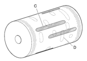
이어서, 도 3은 도 2의 필름 롤의 일정 시간 경과 후의 필름 롤에 대한 권취 코어측을 나타내는 개략도를 나타낸다.Next, FIG. 3 shows a schematic diagram showing the winding core side of the film roll of FIG. 2 after a certain period of time has elapsed.
필름 롤로 했을 때에, 필름끼리가 접촉하는 면 중 권취 코어측의 면(이하 권취 코어측의 면이라고도 한다.)에서는, 시간 경과와 함께 에어층(공기층)의 공기가 더 조금씩 빠짐으로써, 도 3과 같이 첩부 부분(첩부 불량; 도 3에 있어서의 D의 부분.)이 여러점 겹쳐, 힘을 빠지게 하기 때문에 도 3과 같이 폭의 미소 주름(주름)에 더하여 길이 주기를 갖는 폭 방향의 첩부(점차 불량; 도 3에 있어서의 C의 부분 참조.)가 발생해버린다.When using a film roll, on the surface on the winding core side (hereinafter also referred to as the surface on the winding core side) of the surfaces where the films come into contact with each other, the air in the air layer (air layer) is released little by little with the passage of time, and as shown in FIG. See the part of C in 3.) will occur.
또한, 단부에 널링 가공한 광학 필름에 있어서, 에어층(공기층)의 도입에 의한 광학 필름의 첩부 억제 기능이나, 물리적인 요철에 의한 권취 어긋남 억제 기능을 우선하면, 트럭 등에 의한 수송 시에 발생하는 진동에 대하여, 에어층(공기층)의 영향에 의해 필름 롤에 강한 충격을 주게 되어, 오히려 필름 롤의 권취 어긋남이 일어나기 쉬워지거나, 계절 변동의 영향도 받기 쉬워져서, 제어가 매우 곤란해져서 문제 해결에 이르지 못하였다고 추정된다.In addition, in the optical film with knurling at the end, if priority is given to the function of suppressing the sticking of the optical film by introducing an air layer (air layer) or the function of suppressing winding misalignment due to physical irregularities, a strong impact is given to the film roll due to the influence of the air layer (air layer) against vibration generated during transport by a truck or the like, and rather, the winding misalignment of the film roll easily occurs or is easily affected by seasonal fluctuations, and control becomes very difficult, and the problem has not been solved. It is estimated.
한편, 본 발명에서는, 단층의 광학 필름이 권취된 필름 롤에 에어층(공기층)을 적절하게 도입하고, 또한 단부에는 널링 가공을 실시하지 않고, 광학 필름끼리가 대향하는 접촉면 전체면에서 적당하고 미소한 접촉을 발생시키는 것에 의해(첩부가 인식되지 않는 레벨) 권취 어긋남의 기능을 분산시킨다고 하는 종래의 기술과는 역전의 발상으로 과제 해결에 이르렀다.On the other hand, in the present invention, an air layer (air layer) is appropriately introduced into a film roll on which a single-layer optical film is wound, and an end portion is not knurled, and an appropriate and minute contact is generated over the entire surface of the contact surface where the optical films face each other (a level where sticking is not recognized).
즉, 본 발명의 광학 필름은, 상기 광학 필름 내의 임의의 점을 중심으로 하여, 직경 1000㎜의 범위 내에서 측정한 막 두께의 평균 최대 고저차 (P-V)ave1이, 0.15 내지 0.40㎛이고, 또한 상기 필름 롤의 중앙부의 외경 Dc와 단부의 외경 De의 비의 값(Dc/De)이, 0.98 내지 1.02인 것을 특징으로 하고, 이 수단에 의해 과제를 해결할 수 있다.That is, the optical film of the present invention is based on any point in the optical film, the average maximum high and low difference (PV) Ave1 of the membrane thickness measured within a range of 1000 mm in diameter, 0.15 to 0.40 μm, and the value of the outer diameter DC of the center of the film roll and the ratio of the outer diameter de of the end of the end of the film roll is 0.98 to 1.02. It is characterized by this means and can be solved by this means.
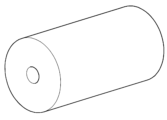
즉, 본 발명의 필름 롤은, 도 4에 도시한 바와 같이, 단부에 널링 가공이 실시되어 있지 않고, 필름 롤 전체면의 막 두께의 평균 최대 고저차, 즉 막 두께 차는 작다.That is, as shown in FIG. 4, the film roll of this invention is not knurled at the edge part, and the average maximum height difference of the film thickness of the whole surface of a film roll, ie, a film thickness difference, is small.
이 때문에, 광학 필름간의 에어층(공기층)이 균일해져서, 필름 롤의 상측이 편평한 상태가 된다.For this reason, the air layer (air layer) between optical films becomes uniform, and the upper side of a film roll becomes a flat state.
필름 롤 하측도 자중의 영향은 있기는 하지만, 상측의 폭 방향의 휨이 없어지는 것으로 하측의 휨이 억제된다.Although the lower side of the film roll is also affected by its own weight, the lower side warpage is suppressed by the disappearance of the upper side warpage in the width direction.
또한, 광학 필름의 권취 코어측의 면에서는 필름 롤의 둘레 방향(길이 방향)의 응력이 균일해지고, 폭 방향에서는, 광학 필름끼리의 볼록부를 중심으로 해서 광학 필름끼리가 접하는 것에 의한 첩부에 의한 응력 집중이 억제된다.In addition, on the surface of the winding core side of the optical film, the stress in the circumferential direction (longitudinal direction) of the film roll becomes uniform, and in the width direction, stress concentration due to sticking caused by optical films contacting each other centering on the convex portion of the optical films is suppressed.
또한, 종래의 광학 필름과 같이 권취 시에 도입되는 에어층(공기층)에 의해 제품부에서의 폭 전체의 접촉을 억제하는 것이 아니고, 광학 필름의 단부에 널링 가공을 하지 않고, 길이 방향의 변동을 고려한 다음, 광학 필름의 폭 방향에 대한 경사 방향의 막 두께의 평균 최대 고저차 (P-V)ave2를 특정 범위로 제어하는 것에 의해서도, 권취 어긋남의 기능을 분산해서 부여함으로써, 수송 시나 장기 보관 시에 감기 불량이 적고, 또한 품질을 유지할 수 있는 필름 롤을 제공할 수 있었다고 추정된다.In addition, instead of suppressing contact across the entire width of the product part by an air layer (air layer) introduced during winding as in the case of a conventional optical film, knurling is not performed on the end of the optical film, variation in the longitudinal direction is taken into account, and then the average maximum height difference (PV) ave2 of the film thickness in the oblique direction with respect to the width direction of the optical film is controlled within a specific range. It is estimated that it was possible to provide a roll of film capable of
또한, 생산 수율이 높고, 검사 부하도 대폭 경감시킨 당해 필름 롤의 제조 방법을 제공할 수 있었다고 추정된다.Moreover, it is estimated that the production yield was high and the manufacturing method of the said film roll which also reduced the inspection load significantly was able to be provided.
또한, 광학 필름의 폭 방향에 대한 경사 방향의 막 두께의 평균 최대 고저차 (P-V)ave2가, 0.15 미만이면 권취 직후부터 첩부가 인식되는 레벨로 되고 있고, 0.40 이상이면 변동에 기인한 미소한 첩부가 발생해서 과제 해결에는 이르지 못하였다.In addition, if the average maximum height difference (PV) ave2 of the film thickness in the oblique direction with respect to the width direction of the optical film is less than 0.15, it is a level at which sticking is recognized immediately after winding, and if it is 0.40 or more, slight sticking due to fluctuation occurs, and the problem has not been solved.
도 1a는 단부가 널링 가공된 필름 롤의 감기 완료 직후(제조 직후)의 개략도
도 1b는 도 1a에 있어서의 필름 롤의 단부의 일부분 A의 확대도
도 1c는 도 1b에 있어서의 널링 가공의 요철 형상의 일부분 B의 필름의 단면 확대도
도 2는 일정 시간 경과 후의 필름 롤의 휨의 상태를 나타내는 개략도
도 3은 일정 시간 경과 후의 필름 롤에 대한 권취 코어측의 면에의 응력이 걸리는 방법을 나타내는 개략도
도 4는 본 발명의 필름 롤 개략도
도 5는 용액 유연 제막법의 제조 공정의 흐름을 나타내는 흐름도
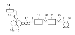
도 6은 용액 유연 제막법에 의해 광학 필름을 제조하는 장치의 개략도
도 7은 텐터 연신 장치의 내부 구성을 모식적으로 나타내는 평면도
도 8은 텐터 연신 장치 내의 3개의 존의 측면도
도 9는 텐터 연신 장치 내의 3개의 존의 평면도
도 10은 텐터 연신 장치 내의 3개의 존을 정면으로부터 보았을 때의 노즐과 히터 설치 부분의 개략도
도 11은 광학 필름이 권취되는 공정과, 권취된 후의 본 발명의 필름 롤 단면을 도시하는 개략도
도 12는 용융 유연 제막법의 제조 공정의 흐름을 나타내는 흐름도
도 13은 용융 유연 제막법에 의해 광학 필름을 제조하는 장치의 개략 구성도1A is a schematic diagram immediately after completion of winding (immediately after manufacture) of a film roll with knurled ends.
Fig. 1B is an enlarged view of a portion A of the end of the film roll in Fig. 1A.
Fig. 1c is an enlarged cross-sectional view of a film of a part B of the concave-convex shape of the knurling process in Fig. 1b.
2 is a schematic diagram showing the state of warping of a film roll after a certain period of time has elapsed.
Fig. 3 is a schematic view showing how stress is applied to the surface of the winding core of the film roll after a certain period of time has elapsed.
4 is a schematic diagram of a film roll of the present invention
5 is a flow chart showing the flow of the manufacturing process of the solution cast film forming method
Figure 6 is a schematic diagram of an apparatus for producing an optical film by a solution cast film forming method
Fig. 7 is a plan view schematically showing the internal configuration of a tenter stretching device;
8 is a side view of three zones in a tenter stretching device;
9 is a plan view of three zones in a tenter stretching device;
Fig. 10 is a schematic view of a nozzle and heater installation portion when three zones in the tenter stretching device are viewed from the front;
Fig. 11 is a schematic view showing a step in which an optical film is wound, and a cross-section of a film roll of the present invention after being wound up;
12 is a flow chart showing the flow of the manufacturing process of the melt casting film forming method
13 is a schematic configuration diagram of an apparatus for manufacturing an optical film by a melt casting film forming method;
본 발명의 필름 롤은, 단층의 광학 필름이 권취된 필름 롤이며, 상기 광학 필름 내의 임의의 점을 중심으로 하여, 직경 1000㎜의 범위 내의 막 두께의 평균 최대 고저차 (P-V)ave1이, 0.15 내지 0.40㎛, 또한 상기 필름 롤의 중앙부와 단부의 비(중앙부의 외경/단부의 외경)가, 0.98 내지 1.02인 것을 특징으로 한다.The film roll of the present invention is a film roll in which a single-layer optical film is wound, and the average maximum height difference (PV) ave1 of the film thickness within the range of 1000 mm in diameter is 0.15 to 0.40 μm, centered at an arbitrary point in the optical film, and the ratio between the central portion and the end portion (outer diameter of the central portion / outer diameter of the end portion) is 0.98 to 1.02.
상기의 특징에 의해, 본 발명의 과제를 해결할 수 있다.The above characteristics can solve the problem of the present invention.
또한, 본 발명의 필름 롤은, 상기 특징에 더하여 상기 필름 롤의 중앙부와 단부의 표면의 반사율로부터 구한 CIE1976L*a*b* 표색계에 의해 규정되는 a*값 및 b*값이 상기 식 (1)을 충족하는 것을 특징으로 한다.In addition to the above characteristics, the film roll of the present invention is characterized in that the a * value and the b * value specified by the CIE1976L * a * b * colorimetric system obtained from the reflectance of the surface of the central and end portions of the film roll satisfy the above formula (1).
상기의 특징에 의해, 본 발명의 과제를 해결할 수 있음과 함께, 광학 필름의 표시 장치에의 적용성을 높이고, 특히 콘트라스트 등이 양호해진다.While being able to solve the subject of this invention by said characteristic, the applicability to the display apparatus of an optical film is improved, and especially contrast etc. become favorable.
상기 두가지 특징은, 하기 실시 양태에 공통되거나 또는 대응하는 기술적 특징이다.The above two features are technical features common to or corresponding to the following embodiments.
본 발명의 실시 형태로서는, 상기 광학 필름의 폭 방향에 대하여 경사 방향으로 상기 스텝 1 내지 스텝 3의 순으로 측정한 막 두께의 평균 최대 고저차 (P-V)ave2가, 0.15 내지 0.40㎛인 것이, 본 발명의 효과 발현의 관점에서 바람직하다.As an embodiment of the present invention, it is preferable from the viewpoint of effect expression of the present invention that the average maximum height difference (PV) ave2 of the film thickness measured in the order of steps 1 to 3 in an oblique direction with respect to the width direction of the optical film is 0.15 to 0.40 μm.
상기 광학 필름 내의 임의의 점을 중심으로 하여, 직경 1000㎜의 범위 내의 평균 차분 배향각 θave° 및 평균 차분 막 두께 dave㎛를 산출했을 때, 평균 차분 배향각 θave°와 평균 차분 막 두께 dave㎛가 상기 식 (2)를 충족하는 것이 본 발명의 효과 발현의 관점에서 바람직하다.When calculating the average differential orientation angle θ ave ° and the average differential film thickness d ave μm within a range of 1000 mm in diameter with an arbitrary point in the optical film as the center, it is preferable from the viewpoint of effect expression of the present invention that the average differential orientation angle θ ave ° and the average differential film thickness d ave μm satisfy the above expression (2).
상기 광학 필름이 무기 미립자를 함유하는 것이, 광학 필름 표면을 적절한 요철 상태로 조정할 수 있는 것 및 저복굴절을 부여하는 관점에서 바람직하고, 내열 보관성의 향상, 환경 안정성의 향상의 관점에서 바람직하다.It is preferable that the optical film contain inorganic fine particles from the viewpoints of being able to adjust the surface of the optical film to an appropriate concavo-convex state and imparting low birefringence, and from the viewpoint of improving heat resistance and environmental stability.
상기 광학 필름의 폭이 2400 내지 3000㎜인 것이 박막화 및 생산성의 관점에서 바람직하다.It is preferable from the viewpoint of thinning and productivity that the width of the optical film is 2400 to 3000 mm.
상기 광학 필름의 길이가 7500 내지 10000m인 것이 박막화 및 생산성의 관점에서 바람직하다.It is preferable from the viewpoint of thinning and productivity that the length of the optical film is 7500 to 10000 m.
본 발명의 필름 롤의 제조 방법은, 상기 필름 롤을 제조하는 필름 롤의 제조 방법이며, 적어도 광학 필름을 연신로 내에서 연신하는 연신 공정 및 평탄화 처리 공정을 갖고, 상기 평탄화 처리 공정에 있어서, 상기 연신로 내의 온도에 대하여 50 내지 200℃의 높은 온도에서 평탄화 처리하는 것, 또한 상기 연신 공정에 있어서, 적외선(IR) 히터를 사용해서 상기 평탄화 처리가 행해지고, 또한, 상기 적외선(IR) 히터의 100㎜ 이격된 위치의 중앙부의 열량 A와 단부의 열량의 평균값 B가 상기 식 (3)을 충족하는 것이, 평탄화의 효과 관점에서 바람직하다.The film roll manufacturing method of the present invention is a film roll manufacturing method for manufacturing the film roll, and includes at least a stretching step of stretching an optical film in a stretching furnace and a flattening treatment step, wherein in the flattening treatment step, the flattening treatment is performed at a high temperature of 50 to 200 ° C. relative to the temperature in the stretching furnace, and in the stretching step, the flattening treatment is performed using an infrared (IR) heater, and the infrared (IR) heater is spaced 100 mm apart From the viewpoint of the flattening effect, it is preferable that the average value B of the heat amount A of the central portion and the heat amount B of the end portion of the position satisfy the above expression (3).
이하, 본 발명과 그 구성 요소 및 본 발명을 실시하기 위한 형태·양태에 대해서 상세한 설명을 한다. 또한, 본원에 있어서, 「내지」는 그 전후에 기재되는 수치를 하한값 및 상한값으로서 포함하는 의미로 사용한다.Hereinafter, detailed explanation is given about the form and aspect for implementing this invention, its component, and this invention. In addition, in this application, "to" is used by the meaning which includes the numerical value described before and after that as a lower limit value and an upper limit value.
1. 본 발명의 필름 롤의 개요1. Outline of the film roll of the present invention
본 발명의 필름 롤은, 단층의 광학 필름이 권취된 필름 롤이며, 상기 광학 필름 내의 임의의 점을 중심으로 하여, 직경 1000㎜의 범위 내의 막 두께의 평균 최대 고저차 (P-V)ave1이 0.15 내지 0.40㎛, 또한 상기 필름 롤의 중앙부와 단부의 비(중앙부의 외경/단부의 외경)가 0.98 내지 1.02인 것을 특징으로 한다.The film roll of the present invention is a film roll on which a single-layer optical film is wound, and is characterized in that the average maximum height difference (PV) ave1 of the film thickness within the range of 1000 mm in diameter is 0.15 to 0.40 μm, centered at an arbitrary point in the optical film, and the ratio between the central portion and the end portion (outer diameter of the central portion / outer diameter of the end portion) is 0.98 to 1.02.
(용어의 정의)(Definition of Terms)
먼저, 이하에 있어서, 본 발명에 관한 주요한 용어의 의의에 대해서 설명한다.First, in the following, the meaning of the main terms related to the present invention will be explained.
「광학 필름의 막 두께의 평균 최대 고저차 (P-V)ave1」란, 후술하는 막 두께 측정에 의해 측정·관찰되는 광학 필름의 두께의 요철 형상의 산과 골의 높이의 최대 고저차를 평균한 값을 말하며, 막 두께를 측정함으로써 광학 필름의 볼록부 구조의 가장 높은 부분과, 오목부 구조의 가장 낮은 부분의 높이의 차를 산출하여, 그 평균값을 (P-V)ave1이라 하였다."Average maximum height difference (PV) ave1 of the film thickness of the optical film" refers to the average value of the maximum height difference of the peaks and valleys of the concavo-convex shape of the thickness of the optical film measured and observed by the film thickness measurement described later. By measuring the film thickness, the difference between the heights of the highest part of the convex structure of the optical film and the lowest part of the concave structure was calculated, and the average value was set as (PV) ave1 .
「단부」란, 광학 필름(롤)의 폭 방향의 말단으로부터 15 내지 30㎜ 내측의 범위 내의 영역 부분을 말한다.The "end" refers to a region portion within a range of 15 to 30 mm from the end of the optical film (roll) in the width direction.
「중앙부」란, 광학 필름의 폭 방향의 양단부를 제외한 영역 부분을 말한다.A "center part" means the area|region part except the both ends of the width direction of an optical film.
「외경」이란, 필름 롤의 중심축(코어)에 수직인 단면을 원으로 했을 때, 롤의 최외주에서 형성되는 원의 직경을 말한다.The "outer diameter" refers to the diameter of a circle formed at the outermost periphery of the roll when a cross section perpendicular to the central axis (core) of the film roll is made into a circle.
따라서, 「단부의 외경」이란, 단부 영역에서 관찰되는 원형의 단면의 직경(평균값)을 말한다.Therefore, the "outer diameter of the end" refers to the diameter (average value) of the circular cross section observed in the end region.
또한, 「중앙부의 외경」이란, 중앙부의 중심점에서 관찰되는 원형의 단면의 직경을 말한다.In addition, the "outer diameter of the central portion" refers to the diameter of the circular cross section observed at the central point of the central portion.
본 발명의 실시예에서는 필름 롤의 폭 방향의 양 말단으로부터 30㎜의 위치의 외경을 줄자에 의해 측정하고, 단부의 외경으로 하였다.In Examples of the present invention, the outer diameter at a position of 30 mm from both ends in the width direction of the film roll was measured with a tape measure, and it was set as the outer diameter of the end.
또한, 단부의 외경은, 양단부의 외경 평균값으로 하였다.In addition, the outer diameter of the end was made into the average value of the outer diameter of both ends.
상기 필름 롤의 외경의 측정에는, 다른 방법도 사용할 수 있고, 예를 들어 레이저 변위계(Keyence사제 LK-G5000)의 레이저를 필름 롤의 폭 방향의 양 말단으로부터 30㎜의 위치의 외경과 중앙부의 중심 위치에 조사하도록 설치해서 외경을 측정할 수도 있다.Other methods can also be used to measure the outer diameter of the film roll. For example, the outer diameter can be measured by installing a laser of a laser displacement meter (LK-G5000 manufactured by Keyence) so as to irradiate the outer diameter at a position of 30 mm from both ends in the width direction of the film roll and the central position of the central portion.
(1.1) 본 발명의 광학 필름의 형상 등(1.1) shape of the optical film of the present invention, etc.
본 발명의 광학 필름은, 상기 광학 필름 내의 임의의 점을 중심으로 하여, 직경 1000㎜의 범위 내에서 측정한 막 두께의 평균 최대 고저차 (P-V)ave1이, 0.15 내지 0.40㎛이다.The optical film of the present invention has an average maximum vertical difference (PV) ave1 of 0.15 to 0.40 µm in film thickness measured within a range of 1000 mm in diameter with an arbitrary point in the optical film as the center.
또한, 상기 필름 롤의 중앙부의 외경 Dc와 단부의 외경 De의 비의 값(Dc/De)이 0.98 내지 1.02이다.In addition, the value of the ratio (Dc/De) of the outer diameter Dc of the central portion and the outer diameter De of the end portion of the film roll is 0.98 to 1.02.
즉, 본 발명의 필름 롤은, 도 4에 도시한 바와 같이, 단부에 널링 가공이 실시되어 있지 않고, 필름 롤 전체면의 막 두께의 평균 최대 고저차, 즉 막 두께 차는 작다.That is, as shown in FIG. 4, the film roll of this invention is not knurled at the edge part, and the average maximum height difference of the film thickness of the whole surface of a film roll, ie, a film thickness difference, is small.
이 때문에, 광학 필름간의 에어층(공기층)이 균일해져서, 필름 롤의 상측이 편평한 상태가 된다.For this reason, the air layer (air layer) between optical films becomes uniform, and the upper side of a film roll becomes a flat state.
필름 롤 하측도 자중의 영향은 있기는 하지만, 상측의 폭 방향의 휨이 없어지는 것으로 하측의 휨이 억제된다.Although the lower side of the film roll is also affected by its own weight, the lower side warpage is suppressed by the disappearance of the upper side warpage in the width direction.
또한, 광학 필름의 권취 코어측의 면에서는 필름 롤의 둘레 방향(길이 방향)의 응력이 균일해지고, 폭 방향에서는, 광학 필름끼리의 볼록부를 중심으로 해서 광학 필름끼리가 접하는 것에 의한 첩부에 의한 응력 집중이 억제된다.In addition, on the surface of the winding core side of the optical film, the stress in the circumferential direction (longitudinal direction) of the film roll becomes uniform, and in the width direction, stress concentration due to sticking caused by optical films contacting each other centering on the convex portion of the optical films is suppressed.
또한, 상기 광학 필름의 폭 방향에 대하여 경사 방향으로 하기 스텝 1 내지 스텝 3의 순으로 측정한 막 두께의 평균 최대 고저차 (P-V)ave2가 0.15 내지 0.40㎛인 것이 상기 작용 기구에 의한 본 발명에 관한 과제 해결의 관점에서 바람직하다.In addition, the average maximum height difference (PV) ave2 of the film thickness measured in the order of steps 1 to 3 below in an oblique direction with respect to the width direction of the optical film is 0.15 to 0.40 μm. It is preferable from the viewpoint of solving the problems related to the present invention by the mechanism.
스텝 1:Step 1:
단부의 임의의 위치에 있어서의 막 두께 측정 후, 측정마다 상기 임의의 위치로부터 폭 방향으로 50㎜, 또한 길이 방향으로 620㎜ 이동시킨 위치의 막 두께를 측정하고, 그것을 다른 쪽 단부까지 반복해서 경사 방향의 최대 고저차를 산출한다.After measuring the film thickness at an arbitrary position at the end, for each measurement, the film thickness at a position moved 50 mm in the width direction and 620 mm in the longitudinal direction from the arbitrary position is measured, and it is repeated to the other end to calculate the maximum height difference in the oblique direction.
스텝 2:Step 2:
상기 스텝 1의 종료 후에, 길이 방향의 이동 위치의 합계의 거리가 1000m에 도달할 때까지 상기 스텝 1과 마찬가지의 측정을 행하여, 경사 방향의 최대 고저차를 더 산출한다.After the completion of step 1, the same measurement as in step 1 is performed until the total distance of the moving positions in the longitudinal direction reaches 1000 m, and the maximum height difference in the oblique direction is further calculated.
스텝 3:Step 3:
상기 스텝 1 및 2에서 얻어진 각 경사 방향의 최대 고저차로부터 경사 방향의 막 두께의 평균 최대 고저차 (P-V)ave2를 산출한다.The average maximum height difference (PV) ave2 of the film thickness in the oblique direction is calculated from the maximum elevation difference in each oblique direction obtained in the
상기 광학 필름 내의 임의의 점을 중심으로 하여, 직경 1000㎜의 범위 내의 평균 차분 배향각 θave° 및 평균 차분 막 두께 dave㎛를 산출했을 때, 평균 차분 배향각 θave°와 평균 차분 막 두께 dave㎛가 하기 식 (2)를 충족하는 것이 효과 발현의 관점에서 바람직하다.When calculating the average differential orientation angle θ ave ° and the average differential film thickness d ave μm within a range of 1000 mm in diameter with an arbitrary point in the optical film as the center, it is preferable from the viewpoint of effect expression that the average differential orientation angle θ ave ° and the average differential film thickness d ave μm satisfy the following expression (2).
식 (2):Equation (2):
800<|평균 차분 배향각 θave/평균 차분 막 두께 dave×10-3|<10000800<|average difference orientation angle θ ave /average difference film thickness d ave ×10 -3 |<10000
여기서, 「평균 차분 배향각 θave」란, 하기 방법으로 측정·산출하여 얻은 값을 말한다.Here, "average difference orientation angle θ ave " refers to a value obtained by measuring and calculating by the following method.
즉, 광학 필름 내의 임의의 점을 중심으로 하여, 직경 1000㎜의 범위 내를 한쪽 단부의 임의의 위치로부터 폭 방향으로 5㎜, 또한 길이 방향으로 5㎜ 이동시킨 위치의 배향각의 값을 측정하고, 그것을 다른 쪽 단부까지 반복해서 측정했다.That is, with an arbitrary point in the optical film as the center, the value of the orientation angle at a position moved by 5 mm in the width direction and 5 mm in the longitudinal direction from an arbitrary position at one end within the range of 1000 mm in diameter was measured, and it was measured repeatedly to the other end.
이어서, 인접하는 배향각의 값의 차분을 취한 절댓값의 평균값을 산출하여, 평균 차분 배향각 θave°라 하였다.Then, the average value of the absolute value obtained by taking the difference between the values of adjacent orientation angles was calculated, and it was set as the average difference orientation angle θ ave °.
또한, 측정의 타이밍은, 용액 유연 제막법, 용융 유연 제막법의 어느 것의 공정에 있어서도, 상온에서 권취 공정 직전으로 하였다.In addition, the timing of the measurement was made just before the winding-up step at room temperature also in any process of the solution cast film forming method and the melt cast film forming method.
「평균 차분 막 두께 dave」란, 하기 방법으로 측정·산출하여 얻은 값을 말한다."Average differential film thickness d ave " refers to a value obtained by measuring and calculating by the method described below.
즉, 광학 필름 내의 임의의 점을 중심으로 하여, 직경 1000㎜의 범위 내를 한쪽 단부의 임의의 위치로부터 폭 방향으로 5㎜, 또한 길이 방향으로 5㎜ 이동시킨 위치의 막 두께의 값을 측정하고, 그것을 다른 쪽 단부까지 반복해서 측정했다.That is, with an arbitrary point in the optical film as the center, the value of the film thickness at a position moved 5 mm in the width direction and 5 mm in the longitudinal direction from an arbitrary position at one end within the range of 1000 mm in diameter was measured, and it was measured repeatedly to the other end.
이어서, 인접하는 막 두께의 값의 차분을 취한 절댓값의 평균값을 산출하여, 평균 차분 막 두께 dave㎛라 하였다.Next, the average value of the absolute value obtained by taking the difference between the adjacent film thickness values was calculated, and it was set as the average difference film thickness d ave μm.
또한, 측정의 타이밍은 용액 유연 제막법, 용융 유연 제막법의 어느 것의 공정에 있어서도, 상온에서 권취 공정 직전으로 하였다.In addition, the timing of the measurement was made just before the winding-up step at normal temperature in either of the solution casting film forming method and the melt casting film forming method.
본 발명에서는, 막 두께의 평균 최대 고저차 (P-V)ave1이, 0.15 내지 0.40과 길이 방향에서 약간의 고저차를 갖고, 또한 |평균 차분 배향각 θave/평균 차분 막 두께 dave×10-3|이 상기와 같이 어느 정도 큰 값을 갖는 필름 롤인 것으로, 인접하는 영역에 있어서 미소한 응력 완화 부분과 비응력 완화 부분을 갖는 광학 필름인 것을 규정하게 되고, 당해 광학 필름 특성에 의해, 국소적인 첩부 시에, 비응력 완화 부분이 국소 완화를 행함으로써 국소적인 첩부를 억제하고 있다는 추측이 성립된다.In the present invention, a film roll having an average maximum height difference (PV) ave1 of film thickness of 0.15 to 0.40 and a slight difference in height in the longitudinal direction, and |average difference orientation angle θ ave /average difference film thickness da ave × 10 -3 | has a large value to some extent as described above, stipulates that it is an optical film having a minute stress relaxation portion and a non-stress relaxation portion in adjacent regions, and localized sticking due to the optical film properties At this time, it is conjectured that the non-stress relieved portion suppresses local sticking by performing local relaxation.
또한, 열 처리를 한 부분은, 광학 필름의 평균 막 두께가 낮아지지만, 배향각을 약간 흐트러뜨리게 되고, 이에 의해 미소한 응력 완화 부분과 비응력 완화 부분을 갖는 광학 필름이 생길 것이라는 추측이 성립되고, 따라서 당업자가 막 두께 편차를 적게 한 필름 롤을 제작할 때에는, 어떠한 열 처리가 필요로 된다고 생각된다.In addition, in the portion subjected to heat treatment, although the average film thickness of the optical film is lowered, the orientation angle is slightly disturbed, and it is conjectured that an optical film having a minute stress relaxation portion and a non-stress relaxation portion will be produced. Therefore, when a person skilled in the art produces a film roll with reduced film thickness variation, some heat treatment is considered necessary.
또한, 상기 소정의 범위 내로 하는 처리를 「평탄화 처리」라고 하며, 그에 대해서는 후술한다.In addition, the process carried out within the said predetermined range is called "flattening process", and it will describe later.
상기 광학 필름이 무기 미립자를 함유하는 것이, 저복굴절을 부여하는 관점에서 바람직하고, 내열 보관성의 향상, 환경 안정성의 향상의 관점에서 바람직하다.It is preferable that the optical film contain inorganic fine particles from the viewpoint of imparting low birefringence, and from the viewpoint of improving heat resistance storage properties and environmental stability.
상기 광학 필름의 폭이 2400 내지 3000㎜의 범위 내인 것이 박막화 및 생산성의 관점에서 바람직하다.It is preferable from the viewpoint of thinning and productivity that the width of the optical film is within the range of 2400 to 3000 mm.
상기 필름 롤의 길이가 7500 내지 10000m의 범위 내인 것이 박막화 및 생산성의 관점에서 바람직하다.It is preferable from the viewpoint of thinning and productivity that the length of the film roll is within the range of 7500 to 10000 m.
(1.2) 광학 필름의 색조의 균일성(1.2) Uniformity of color tone of optical film
본 발명의 필름 롤의 실시 형태의 다른 예로서는, 중앙부와 단부의 표면의 분광 반사율로부터 구한 CIE1976L*a*b* 표색계에 의해 규정되는 a*값 및 b*값이 하기 식 (1)을 충족하는 것을 특징으로 한다.As another example of embodiment of the film roll of the present invention, the a * value and the b * value defined by the CIE1976L * a * b * colorimetric system obtained from the spectral reflectance of the surface of the central portion and the end portion satisfy the following formula (1).
이러한 특성을 충족한다는 것은, 광학 필름의 장소에 의한 색상 및 채도의 차이가 적어, 광학 필름의 색조가 전체적으로 균일한 점에서, 광학 필름 표면의 요철 상태가 균일하고, 본 발명에 관한 과제 해결의 관점 및 광학 필름을 표시 장치에 적용한 경우, 콘트라스트가 양호한 화상을 얻기 쉽다.Satisfying these characteristics means that the difference in color and saturation depending on the location of the optical film is small, the color tone of the optical film is uniform as a whole, the surface of the optical film has a uniform uneven state, and from the viewpoint of solving the problems related to the present invention, and when the optical film is applied to a display device, it is easy to obtain an image with good contrast.
식 (1):Equation (1):
-1.0<(단부 a*-중앙부 a*)+(단부 b*-중앙부 b*)<1.0-1.0<(end a * -center a * )+(end b * -center b * )<1.0
(상기 식 중, a*값은 상기 표색계 중 색상과 채도를 나타내고, 적-녹 추이 선의 위치를 나타내는 좌푯값이다. b*값은 상기 표색계 중 색상과 채도를 나타내고, 황-청 추이선의 위치를 나타내는 좌푯값이다.)(In the above formula, the a * value represents hue and saturation in the colorimetric system and is a coordinate value representing the position of the red-green trend line. The b * value represents the hue and chroma in the colorimetric system and is a coordinate value representing the position of the yellow-blue transition line.)
또한, a*값 및 b*값의 측정은 측색계를 사용해서 할 수 있다. 예를 들어, 팔레트 큐브(Palette CUBE; Palette Pty Ltd제)에 의해 측정할 수 있다.In addition, the measurement of a * value and b * value can be performed using a colorimeter. For example, it can be measured by Palette CUBE (manufactured by Palette Pty Ltd).
2. 광학 필름을 구성하는 수지2. Resin constituting the optical film
(2.1) 열가소성 수지(2.1) thermoplastic resin
본 발명에 관한 광학 필름에 사용되는 열가소성 수지 재료로서는, 제막 후 필름 롤로서 취급할 수 있는 것이면 한정은 없다.The thermoplastic resin material used for the optical film according to the present invention is not limited as long as it can be handled as a film roll after film formation.
예를 들어 편광판 용도로서 사용되고 있는 열가소성 수지로서는, 트리아세틸셀룰로오스(TAC), 셀룰로오스아세테이트프로피오네이트(CAP), 디아세틸셀룰로오스(DAC) 등의 셀룰로오스에스테르계 수지나 시클로올레핀폴리머(시클로올레핀계 수지(COP)) 등의 환상 올레핀계 수지(이하, 시클로올레핀계 수지라고도 한다.), 폴리프로필렌(PP) 등의 폴리프로필렌계 수지, 폴리메틸메타크릴레이트(PMMA) 등의 아크릴계 수지 및 폴리에틸렌테레프탈레이트(PET) 등의 폴리에스테르계 수지를 적용할 수 있다.Examples of thermoplastic resins used for polarizing plate applications include cellulose ester-based resins such as triacetyl cellulose (TAC), cellulose acetate propionate (CAP), and diacetyl cellulose (DAC), cyclic olefin-based resins such as cycloolefin polymers (cycloolefin-based resins (COP)) (hereinafter also referred to as cycloolefin-based resins), polypropylene resins such as polypropylene (PP), acrylic resins such as polymethyl methacrylate (PMMA), and polyethylene terephthalate. (PET) and the like can be applied.
특히, 저탄성률의 광학 필름, 예를 들어 탄성률 3.0㎬ 미만의 수지에 있어서는 필름 롤을 형성할 때에 당해 필름의 복수의 개소에 관한 응력을 완화하기 어렵기 때문에, 폭 방향 및 길이 방향으로 신축하기 어려워져서, 당해 광학 필름이 롤의 상태에서는 면에서 응력을 끝까지 흡수하지 못하여, 권취 어긋남이 일어나기 쉽다.In particular, in an optical film having a low elastic modulus, for example, a resin having an elastic modulus of less than 3.0 GPa, it is difficult to relieve stress at a plurality of locations of the film when forming a film roll, so that it is difficult to stretch and contract in the width direction and the longitudinal direction.
또한, 상기의 저탄성률 광학 필름을 다른 관점에서 보면, 당해 광학 필름의 길이 방향 및 길이 방향에서 고저차가 있으면, 당해 광학 필름의 높은 곳의 신축과 낮은 곳의 신축의 차가 커져버린다.In addition, when the above low elastic modulus optical film is viewed from another viewpoint, if there is a height difference between the longitudinal direction and the longitudinal direction of the optical film, the difference between the expansion and contraction of the optical film at a high position and the expansion and contraction at a low position becomes large.
따라서, 본 발명의 실시 형태에 있어서, 길이 방향의 변동을 고려한 다음, 광학 필름의 폭 방향에 대한 경사 방향의 막 두께의 평균 최대 고저차 (P-V)ave1을 특정 범위로 제어하는 것이 바람직하고, 저탄성률의 수지인 시클로올레핀폴리머(시클로올레핀계 수지(COP))나 폴리메틸메타크릴레이트(아크릴계 수지(PMMA))를 열가소성 수지로서 사용한 필름 롤에 적용하는 것이 효과적이다.Therefore, in the embodiment of the present invention, it is preferable to control the average maximum height difference (PV) ave1 of the film thickness in the oblique direction with respect to the width direction of the optical film in a specific range after considering the variation in the longitudinal direction, and it is effective to apply to a film roll using a cycloolefin polymer (cycloolefin resin (COP)) or polymethyl methacrylate (acrylic resin (PMMA)), which is a resin with a low elastic modulus, as a thermoplastic resin.
단, 연신성이나 결정화도의 컨트롤이 하기 쉬운 점 및 접착제가 침투하기 쉽고, 편광자와의 보다 양호한 접착성을 확보할 수 있는 점에서는, 시클로올레핀계 수지(COP)를 사용하는 것이 바람직하다.However, it is preferable to use a cycloolefin-based resin (COP) in terms of easy control of stretchability and crystallinity, easy permeation of the adhesive, and better adhesion to the polarizer.
또한, 상기 광학 필름은 제조 후에 표면 개질 처리를 실시해도 된다.In addition, the optical film may be subjected to surface modification treatment after production.
또한, 본 발명의 효과는 박막 영역에서 가치가 높아진다.In addition, the effect of the present invention increases in value in the thin film area.
광학 필름의 막 두께로서는 5 내지 80㎛의 범위 내가 바람직하고, 10 내지 65㎛의 범위 내가 보다 바람직하고, 10 내지 45㎛의 범위 내가 더욱 바람직하다.The film thickness of the optical film is preferably within a range of 5 to 80 µm, more preferably within a range of 10 to 65 µm, and even more preferably within a range of 10 to 45 µm.
막 두께가 5㎛ 이상이면, 필름 롤의 강성이 높고, 롤 형상을 유지하는 것이 용이하게 된다.When the film thickness is 5 μm or more, the rigidity of the film roll is high and it becomes easy to maintain the roll shape.
막 두께가 80㎛ 이하이면 질량이 너무 증가하지 않고, 긴 필름 롤을 제작하기 쉬워진다.When the film thickness is 80 μm or less, the mass does not increase too much and it becomes easy to produce a long film roll.
(2.1.1) 시클로올레핀계 수지(2.1.1) cycloolefin resin
본 발명의 필름 롤에 함유되는 시클로올레핀계 수지는, 시클로올레핀 단량체의 중합체, 또는 시클로올레핀 단량체와 그 이외의 공중합성 단량체의 공중합체인 것이 바람직하다.It is preferable that the cycloolefin resin contained in the film roll of this invention is a polymer of a cycloolefin monomer or a copolymer of a cycloolefin monomer and another copolymerizable monomer.
시클로올레핀 단량체로서는, 노르보르넨 골격을 갖는 시클로올레핀 단량체인 것이 바람직하고, 하기 일반식 (A-1) 또는 (A-2)로 표시되는 구조를 갖는 시클로올레핀 단량체인 것이 보다 바람직하다.The cycloolefin monomer is preferably a cycloolefin monomer having a norbornene skeleton, and more preferably a cycloolefin monomer having a structure represented by the following general formula (A-1) or (A-2).
일반식 (A-1) 중, R1 내지 R4는, 각각 독립적으로, 수소 원자, 탄소 원자수 1 내지 30의 탄화수소기, 또는 극성기를 나타낸다. p는 0 내지 2의 정수를 나타낸다. 단, R1 내지 R4 모두가 동시에 수소 원자를 나타내지 않고, R1과 R2가 동시에 수소 원자를 나타내지 않고, R3과 R4가 동시에 수소 원자를 나타내는 일은 없는 것으로 한다.In the general formula (A-1), R 1 to R 4 each independently represent a hydrogen atom, a hydrocarbon group having 1 to 30 carbon atoms, or a polar group. p represents an integer from 0 to 2; However, it is assumed that none of R 1 to R 4 simultaneously represent a hydrogen atom, R 1 and R 2 do not simultaneously represent a hydrogen atom, and R 3 and R 4 do not represent a hydrogen atom simultaneously.
일반식 (A-1)에 있어서 R1 내지 R4로 표현되는 탄소 원자수 1 내지 30의 탄화수소기로서는, 예를 들어 탄소 원자수 1 내지 10의 탄화수소기인 것이 바람직하고, 탄소 원자수 1 내지 5의 탄화수소기인 것이 보다 바람직하다.The hydrocarbon group having 1 to 30 carbon atoms represented by R 1 to R 4 in the general formula (A-1) is, for example, preferably a hydrocarbon group having 1 to 10 carbon atoms, and more preferably a hydrocarbon group having 1 to 5 carbon atoms.
탄소 원자수 1 내지 30의 탄화수소기는, 예를 들어 할로겐 원자, 산소 원자, 질소 원자, 황 원자 또는 규소 원자를 포함하는 연결기를 더 갖고 있어도 된다.The hydrocarbon group of 1 to 30 carbon atoms may further have a linking group containing, for example, a halogen atom, an oxygen atom, a nitrogen atom, a sulfur atom, or a silicon atom.
그러한 연결기의 예에는, 카르보닐기, 이미노기, 에테르 결합, 실릴에테르 결합, 티오에테르 결합 등의 2가의 극성기가 포함된다.Examples of such a linking group include divalent polar groups such as a carbonyl group, an imino group, an ether bond, a silyl ether bond, and a thioether bond.
탄소 원자수 1 내지 30의 탄화수소기 예에는 메틸기, 에틸기, 프로필기 및 부틸기 등이 포함된다.Examples of hydrocarbon groups having 1 to 30 carbon atoms include methyl, ethyl, propyl and butyl groups.
일반식 (A-1)에 있어서 R1 내지 R4로 표현되는 극성기의 예에는, 카르복시기, 히드록시기, 알콕시기, 알콕시카르보닐기, 아릴옥시카르보닐기, 아미노기, 아미드기 및 시아노기가 포함된다.Examples of the polar group represented by R 1 to R 4 in the general formula (A-1) include a carboxy group, a hydroxy group, an alkoxy group, an alkoxycarbonyl group, an aryloxycarbonyl group, an amino group, an amide group and a cyano group.
그 중에서도, 카르복시기, 히드록시기, 알콕시카르보닐기 및 아릴옥시카르보닐기가 바람직하고, 용액 제막 시의 용해성을 확보하는 관점에서, 알콕시카르보닐기 및 아릴옥시카르보닐기가 바람직하다.Especially, a carboxy group, a hydroxyl group, an alkoxycarbonyl group, and an aryloxycarbonyl group are preferable, and an alkoxycarbonyl group and an aryloxycarbonyl group are preferable from the viewpoint of ensuring solubility during solution film formation.
일반식 (A-1)에 있어서의 p는, 광학 필름의 내열성을 높이는 관점에서, 1 또는 2인 것이 바람직하다.It is preferable that p in General formula (A-1) is 1 or 2 from a viewpoint of improving the heat resistance of an optical film.
p가 1 또는 2이면, 얻어지는 중합체가 부피가 커지고, 유리 전이 온도가 향상되기 쉽기 때문이다.It is because when p is 1 or 2, the volume of the obtained polymer increases and the glass transition temperature tends to increase.
일반식 (A-2) 중, R5는 수소 원자, 탄소수 1 내지 5의 탄화수소기, 또는 탄소수 1 내지 5의 알킬기를 갖는 알킬실릴기를 나타낸다. R6은 카르복시기, 히드록시기, 알콕시카르보닐기, 아릴옥시카르보닐기, 아미노기, 아미드기, 시아노기, 또는 할로겐 원자(불소 원자, 염소 원자, 브롬 원자 혹은 요오드 원자)를 나타낸다. p는 0 내지 2의 정수를 나타낸다.In the general formula (A-2), R 5 represents a hydrogen atom, a hydrocarbon group having 1 to 5 carbon atoms, or an alkylsilyl group having an alkyl group having 1 to 5 carbon atoms. R 6 represents a carboxy group, a hydroxy group, an alkoxycarbonyl group, an aryloxycarbonyl group, an amino group, an amide group, a cyano group, or a halogen atom (fluorine atom, chlorine atom, bromine atom or iodine atom). p represents an integer from 0 to 2;
일반식 (A-2)에 있어서의 R5는 탄소수 1 내지 5의 탄화수소기를 나타내는 것이 바람직하고, 탄소수 1 내지 3의 탄화수소기를 나타내는 것이 보다 바람직하다.R 5 in the general formula (A-2) preferably represents a hydrocarbon group of 1 to 5 carbon atoms, and more preferably represents a hydrocarbon group of 1 to 3 carbon atoms.
일반식 (A-2)에 있어서의 R6은 카르복시기, 히드록시기, 알콕시카르보닐기 및 아릴옥시카르보닐기를 나타내는 것이 바람직하고, 용액 제막 시의 용해성을 확보하는 관점에서, 알콕시카르보닐기 및 아릴옥시카르보닐기가 보다 바람직하다.R 6 in the general formula (A-2) preferably represents a carboxy group, a hydroxy group, an alkoxycarbonyl group, or an aryloxycarbonyl group, and from the viewpoint of ensuring solubility during solution film formation, an alkoxycarbonyl group or an aryloxycarbonyl group is more preferred.
일반식 (A-2)에 있어서의 p는, 광학 필름의 내열성을 높이는 관점에서, 1 또는 2를 나타내는 것이 바람직하다.It is preferable that p in General formula (A-2) represents 1 or 2 from a viewpoint of improving the heat resistance of an optical film.
p가 1 또는 2를 나타내면, 얻어지는 중합체가 부피가 커지고, 유리 전이 온도가 향상되기 쉽기 때문이다.It is because when p represents 1 or 2, the polymer obtained becomes bulky and the glass transition temperature tends to improve.
일반식 (A-2)로 표시되는 구조를 갖는 시클로올레핀 단량체는, 유기 용매에 대한 용해성을 향상시키는 점에서 바람직하다.A cycloolefin monomer having a structure represented by general formula (A-2) is preferable from the viewpoint of improving solubility in organic solvents.
일반적으로 유기 화합물은 대칭성을 무너뜨리는 것에 의해 결정성이 저하하기 때문에, 유기 용매에 대한 용해성이 향상된다.Since the crystallinity of an organic compound generally decreases by breaking symmetry, solubility to an organic solvent improves.
일반식 (A-2)에 있어서의 R5 및 R6은 분자의 대칭축에 대하여 편측의 환 구성 탄소 원자만으로 치환되어 있으므로, 분자의 대칭성이 낮고, 즉 일반식 (A-2)로 표시되는 구조를 갖는 시클로올레핀 단량체는 용해성이 높기 때문에, 광학 필름을 용액 유연법에 의해 제조하는 경우에 적합하다.Since R 5 and R 6 in the general formula (A-2) are substituted only with ring-constituting carbon atoms on one side with respect to the axis of symmetry of the molecule, the molecular symmetry is low, that is, since the cycloolefin monomer having the structure represented by the general formula (A-2) has high solubility, it is suitable for producing an optical film by a solution casting method.
시클로올레핀 단량체의 중합체에 있어서의 일반식 (A-2)로 표시되는 구조를 갖는 시클로올레핀 단량체의 함유 비율은, 시클로올레핀계 수지를 구성하는 전체 시클로올레핀 단량체의 합계에 대하여, 예를 들어 70몰% 이상, 바람직하게는 80몰% 이상, 보다 바람직하게는 100몰%로 할 수 있다.The content ratio of the cycloolefin monomer having the structure represented by the general formula (A-2) in the polymer of the cycloolefin monomer is, for example, 70 mol% or more, preferably 80 mol% or more, more preferably 100 mol% with respect to the total of all cycloolefin monomers constituting the cycloolefin resin.
일반식 (A-2)로 표시되는 구조를 갖는 시클로올레핀 단량체를 일정 이상 포함하면, 수지의 배향성이 높아지기 때문에, 위상차(리타데이션)값이 상승하기 쉽다.When a certain amount or more of the cycloolefin monomer having a structure represented by the general formula (A-2) is included, the orientation of the resin increases, so that the phase difference (retardation) value tends to increase.
이하, 일반식 (A-1)로 표시되는 구조를 갖는 시클로올레핀 단량체의 구체예를 예시 화합물 1 내지 14로 나타내고, 일반식 (A-2)로 표시되는 구조를 갖는 시클로올레핀 단량체의 구체예를 예시 화합물 15 내지 34로 나타낸다.Hereinafter, specific examples of the cycloolefin monomer having a structure represented by the general formula (A-1) are shown as Exemplary Compounds 1 to 14, and specific examples of the cycloolefin monomer having a structure represented by the General Formula (A-2) are shown as
시클로올레핀 단량체와 공중합 가능한 공중합성 단량체의 예에는, 시클로올레핀 단량체와 개환 공중합 가능한 공중합성 단량체 및 시클로올레핀 단량체와 부가 공중합 가능한 공중합성 단량체 등이 포함된다.Examples of the copolymerizable monomer copolymerizable with the cycloolefin monomer include a copolymerizable monomer capable of ring-opening copolymerization with the cycloolefin monomer and a copolymerizable monomer capable of addition copolymerization with the cycloolefin monomer.
개환 공중합 가능한 공중합성 단량체의 예에는, 시클로부텐, 시클로펜텐, 시클로헵텐, 시클로옥텐 및 디시클로펜타디엔 등의 시클로올레핀이 포함된다.Examples of the copolymerizable monomer capable of ring-opening copolymerization include cycloolefins such as cyclobutene, cyclopentene, cycloheptene, cyclooctene and dicyclopentadiene.
부가 공중합 가능한 공중합성 단량체의 예에는, 불포화 이중 결합 함유 화합물, 비닐계 환상 탄화수소 단량체 및 (메트)아크릴레이트 등이 포함된다.Examples of the copolymerizable monomer capable of addition copolymerization include unsaturated double bond-containing compounds, vinyl-based cyclic hydrocarbon monomers, and (meth)acrylates.
불포화 이중 결합 함유 화합물의 예에는, 탄소 원자수 2 내지 12(바람직하게는 2 내지 8)의 올레핀계 화합물이 포함되고, 그 예에는, 에틸렌, 프로필렌 및 부텐 등이 포함된다.Examples of the unsaturated double bond-containing compound include olefinic compounds having 2 to 12 (preferably 2 to 8) carbon atoms, and examples thereof include ethylene, propylene, and butene.
비닐계 환상 탄화수소 단량체의 예에는, 4-비닐시클로펜텐 및 2-메틸-4-이소프로페닐시클로펜텐 등의 비닐시클로펜텐계 단량체가 포함된다.Examples of the vinyl-based cyclic hydrocarbon monomer include vinylcyclopentene-based monomers such as 4-vinylcyclopentene and 2-methyl-4-isopropenylcyclopentene.
(메트)아크릴레이트의 예에는, 메틸(메트)아크릴레이트, 2-에틸헥실(메트)아크릴레이트 및 시클로헥실(메트)아크릴레이트 등의 탄소 원자수 1 내지 20의 알킬 (메트)아크릴레이트가 포함된다.Examples of (meth)acrylates include alkyl (meth)acrylates having 1 to 20 carbon atoms, such as methyl (meth)acrylate, 2-ethylhexyl (meth)acrylate and cyclohexyl (meth)acrylate.
시클로올레핀 단량체와 공중합성 단량체의 공중합체에 있어서의 시클로올레핀 단량체의 함유 비율은, 공중합체를 구성하는 전체 단량체의 합계에 대하여, 예를 들어 20 내지 80mol%의 범위 내, 바람직하게는 30 내지 70mol%의 범위 내로 할 수 있다.The content ratio of the cycloolefin monomer in the copolymer of the cycloolefin monomer and the copolymerizable monomer is, for example, within the range of 20 to 80 mol%, preferably within the range of 30 to 70 mol% with respect to the total of all monomers constituting the copolymer.
시클로올레핀계 수지는, 전술한 바와 같이, 노르보르넨 골격을 갖는 시클로올레핀 단량체, 바람직하게는 일반식 (A-1) 또는 (A-2)로 표시되는 구조를 갖는 시클로올레핀 단량체를 중합 또는 공중합해서 얻어지는 중합체이며, 그 예에는, 이하(1) 내지 (7)의 중합체가 포함된다.As described above, the cycloolefin resin is a polymer obtained by polymerizing or copolymerizing a cycloolefin monomer having a norbornene skeleton, preferably a cycloolefin monomer having a structure represented by the general formula (A-1) or (A-2), and examples thereof include the following polymers (1) to (7).
(1) 시클로올레핀 단량체의 개환 중합체(1) Ring-opening polymer of cycloolefin monomer
(2) 시클로올레핀 단량체와, 그것과 개환 공중합 가능한 공중합성 단량체의 개환 공중합체(2) A ring-opening copolymer of a cycloolefin monomer and a copolymerizable monomer capable of ring-opening copolymerization therewith
(3) 상기 (1) 또는 (2)의 개환 (공)중합체의 수소 첨가물(3) Hydrogenated product of the ring-opening (co)polymer of (1) or (2) above
(4) 상기 (1) 또는 (2)의 개환 (공)중합체를 프리델 크래프츠 반응에 의해 환화한 후, 수소를 첨가한 (공)중합체(4) The (co)polymer obtained by cyclizing the ring-opening (co)polymer of (1) or (2) by Friedel Crafts reaction and then adding hydrogen thereto
(5) 시클로올레핀 단량체와, 불포화 이중 결합 함유 화합물의 포화 공중합체(5) Saturated copolymers of cycloolefin monomers and compounds containing unsaturated double bonds
(6) 시클로올레핀 단량체의 비닐계 환상 탄화수소 단량체와의 부가 공중합체 및 그 수소 첨가물(6) Addition copolymers of cycloolefin monomers with vinyl-based cyclic hydrocarbon monomers and hydrogenated products thereof
(7) 시클로올레핀 단량체와, (메트)아크릴레이트의 교호 공중합체(7) alternating copolymer of cycloolefin monomer and (meth)acrylate
상기 (1) 내지 (7)의 중합체는, 모두 공지된 방법, 예를 들어 일본특허공개 2008-107534호 공보나 일본특허공개 2005-227606호 공보에 기재된 방법으로 얻을 수 있다.All of the above (1) to (7) polymers can be obtained by a known method, for example, a method described in Japanese Patent Application Laid-Open No. 2008-107534 or Japanese Patent Laid-Open No. 2005-227606.
예를 들어 상기 (2)의 개환 공중합에 사용되는 촉매나 용매는, 예를 들어 일본특허공개 2008-107534호 공보의 단락 0019 내지 0024에 기재된 것을 사용할 수 있다.For example, as the catalyst or solvent used for the ring-opening copolymerization of the above (2), those described in paragraphs 0019 to 0024 of Unexamined-Japanese-Patent No. 2008-107534 can be used, for example.
상기 (3) 및 (6)의 수소 첨가물에 사용되는 촉매는, 예를 들어 일본특허공개 2008-107534호 공보의 단락 0025 내지 0028에 기재된 것을 사용할 수 있다.As the catalyst used in the hydrogenation product of the above (3) and (6), for example, those described in paragraphs 0025 to 0028 of JP-A-2008-107534 can be used.
상기 (4)의 프리델 크래프츠 반응에 사용되는 산성 화합물은, 예를 들어 일본특허공개 2008-107534호 공보의 단락 0029에 기재된 것을 사용할 수 있다.As the acidic compound used in the Friedel Crafts reaction of the above (4), for example, those described in paragraph 0029 of Japanese Unexamined Patent Publication No. 2008-107534 can be used.
상기 (5) 내지 (7)의 부가 중합에 사용되는 촉매는, 예를 들어 일본특허공개 2005-227606호 공보의 단락 0058 내지 0063에 기재된 것을 사용할 수 있다.As the catalyst used for the addition polymerization of the above (5) to (7), those described in, for example, paragraphs 0058 to 0063 of Japanese Patent Laid-Open No. 2005-227606 can be used.
상기 (7)의 교대 공중합 반응은, 예를 들어 일본특허공개 2005-227606호 공보의 단락 0071 및 0072에 기재된 방법으로 행할 수 있다.The alternating copolymerization reaction of the above (7) can be carried out, for example, by the method described in paragraphs 0071 and 0072 of Japanese Unexamined Patent Publication No. 2005-227606.
그 중에서도, 상기 (1) 내지 (3) 및 (5)의 중합체가 바람직하고, 상기 (3) 및 (5)의 중합체가 보다 바람직하다.Especially, the polymer of said (1)-(3) and (5) is preferable, and the polymer of said (3) and (5) is more preferable.
즉, 시클로올레핀계 수지는, 얻어지는 시클로올레핀계 수지의 유리 전이 온도를 높게 하고, 또한 광투과율을 높게 할 수 있는 점에서, 하기 일반식 (B-1)로 표시되는 구조 단위와 하기 일반식 (B-2)로 표시되는 구조 단위의 적어도 한쪽을 포함하는 것이 바람직하고, 일반식 (B-2)로 표시되는 구조 단위만을 포함하거나, 또는 일반식 (B-1)로 표시되는 구조 단위와 일반식 (B-2)로 표시되는 구조 단위의 양쪽을 포함하는 것이 보다 바람직하다.That is, the cycloolefin-based resin preferably contains at least one of a structural unit represented by the following general formula (B-1) and a structural unit represented by the following general formula (B-2), from the viewpoint of which the glass transition temperature of the obtained cycloolefin-based resin can be increased and the light transmittance can be increased, and contains only the structural unit represented by the general formula (B-2), or contains both the structural unit represented by the general formula (B-1) and the structural unit represented by the general formula (B-2) it is more preferable
일반식 (B-1)로 표시되는 구조 단위는, 전술한 일반식 (A-1)로 표시되는 시클로올레핀 단량체 유래의 구조 단위이며, 일반식 (B-2)로 표시되는 구조 단위는, 전술한 일반식 (A-2)로 표시되는 시클로올레핀 단량체 유래의 구조 단위이다.The structural unit represented by the general formula (B-1) is a structural unit derived from the cycloolefin monomer represented by the above-described general formula (A-1), and the structural unit represented by the general formula (B-2) is a structural unit derived from the cycloolefin monomer represented by the above-described general formula (A-2).
일반식 (B-1) 중, X는 -CH=CH- 또는 -CH2CH2-를 나타낸다. R1 내지 R4 및 p는, 각각 일반식 (A-1)의 R1 내지 R4 및 p와 동일한 의미이다.In general formula (B-1), X represents -CH=CH- or -CH 2 CH 2 -. R 1 to R 4 and p have the same meaning as R 1 to R 4 and p in the general formula (A-1), respectively.
일반식 (B-2) 중, X는 -CH=CH- 또는 -CH2CH2-을 나타낸다. R5 내지 R6 및 p는, 각각 일반식 (A-2)의 R5 내지 R6 및 p와 동일한 의미이다.In general formula (B-2), X represents -CH=CH- or -CH 2 CH 2 -. R 5 to R 6 and p have the same meaning as R 5 to R 6 and p in the general formula (A-2), respectively.
본 발명에 관한 시클로올레핀계 수지는, 시판품이어도 된다.A commercial item may be sufficient as the cycloolefin resin which concerns on this invention.
시클로올레핀계 수지의 시판품 예에는, JSR(주) 제의 아톤(Arton) G(예를 들어 G7810 등), 아톤 F, 아톤 R(예를 들어 R4500, R4900 및 R5000 등) 및 아톤 RX가 포함된다.Examples of commercially available cycloolefin resins include Arton G (eg G7810, etc.), Arton F, Arton R (eg R4500, R4900 and R5000) and Arton RX manufactured by JSR Co., Ltd.
시클로올레핀계 수지의 고유 점도 〔η〕inh는, 30℃의 측정에 있어서, 0.2 내지 5㎤/g의 범위 내인 것이 바람직하고, 0.3 내지 3㎤/g의 범위 내인 것이 보다 바람직하고, 0.4 내지 1.5㎤/g의 범위 내인 것이 더욱 바람직하다.The intrinsic viscosity [η] inh of the cycloolefin resin is preferably in the range of 0.2 to 5 cm / g, more preferably in the range of 0.3 to 3 cm / g, and even more preferably in the range of 0.4 to 1.5 cm / g, measured at 30 ° C.
시클로올레핀계 수지의 수 평균 분자량(Mn)은 8000 내지 100000의 범위 내인 것이 바람직하고, 10000 내지 80000의 범위 내인 것이 보다 바람직하고, 12000 내지 50000의 범위 내인 것이 더욱 바람직하다.The number average molecular weight (Mn) of the cycloolefin resin is preferably in the range of 8000 to 100000, more preferably in the range of 10000 to 80000, and still more preferably in the range of 12000 to 50000.
시클로올레핀계 수지의 중량 평균 분자량(Mw)은 20000 내지 300000의 범위 내인 것이 바람직하고, 30000 내지 250000의 범위 내인 것이 보다 바람직하고, 40000 내지 200000의 범위 내인 것이 더욱 바람직하다.The weight average molecular weight (Mw) of the cycloolefin resin is preferably in the range of 20000 to 300000, more preferably in the range of 30000 to 250000, still more preferably in the range of 40000 to 200000.
시클로올레핀계 수지의 수 평균 분자량이나 중량 평균 분자량은 겔 투과 크로마토그래피(GPC)로 폴리스티렌 환산으로 측정할 수 있다.The number average molecular weight and weight average molecular weight of the cycloolefin resin can be measured in terms of polystyrene by gel permeation chromatography (GPC).
(겔 투과 크로마토그래피)(Gel Permeation Chromatography)
용매: 메틸렌클로라이드Solvent: Methylene chloride
칼럼: Shodex K806, K805, K803G(쇼와 덴코(주) 제를 3개 접속해서 사용했다)Column: Shodex K806, K805, K803G (three products manufactured by Showa Denko Co., Ltd. were connected and used)
칼럼 온도: 25℃Column temperature: 25°C
시료 농도: 0.1질량%Sample concentration: 0.1% by mass
검출기: RI Model 504(GL 사이언스사제)Detector: RI Model 504 (manufactured by GL Science)
펌프: L6000(히다치 세이사꾸쇼(주) 제)Pump: L6000 (manufactured by Hitachi Seisakusho Co., Ltd.)
유량: 1.0ml/minFlow: 1.0ml/min
교정 곡선: 표준 폴리스티렌 STK standard 폴리스티렌(도소(주) 제)Mw=500 내지 2800000의 범위 내의 13 샘플에 의한 교정 곡선을 사용했다. 13 샘플은, 거의 등간격으로 사용하는 것이 바람직하다.Calibration curve: Standard polystyrene STK standard polystyrene (manufactured by Tosoh Co., Ltd.) Mw = A calibration curve by 13 samples within the range of 500 to 2800000 was used. It is preferable to use 13 samples at substantially equal intervals.
고유 점도 〔η〕inh, 수 평균 분자량 및 중량 평균 분자량이 상기 범위에 있으면, 시클로올레핀계 수지의 내열성, 내수성, 내약품성, 기계적 특성 및 필름으로서의 성형 가공성이 양호해진다.When the intrinsic viscosity [η] inh, number average molecular weight, and weight average molecular weight are within the above ranges, the heat resistance, water resistance, chemical resistance, mechanical properties, and moldability of the cycloolefin-based resin as a film become good.
시클로올레핀계 수지의 유리 전이 온도(Tg)는, 통상 110℃ 이상이고, 110 내지 350℃의 범위 내인 것이 바람직하고, 120 내지 250℃의 범위 내인 것이 보다 바람직하고, 120 내지 220℃의 범위 내인 것이 더욱 바람직하다.The glass transition temperature (Tg) of the cycloolefin-based resin is usually 110 ° C. or higher, preferably within the range of 110 to 350 ° C., more preferably within the range of 120 to 250 ° C., still more preferably within the range of 120 to 220 ° C.
유리 전이 온도(Tg)가 110℃ 이상이면 고온 조건 하에서의 변형을 억제하기 쉽다.When the glass transition temperature (Tg) is 110°C or higher, deformation under high-temperature conditions is easily suppressed.
한편, 유리 전이 온도(Tg)가 350℃ 이하이면, 성형 가공이 용이해지고, 성형 가공 시의 열에 의한 수지의 열화도 억제하기 쉽다.On the other hand, when the glass transition temperature (Tg) is 350° C. or lower, the molding process becomes easy, and the deterioration of the resin due to heat during the molding process is also easily suppressed.
시클로올레핀계 수지의 함유량은, 필름에 대하여 70질량% 이상인 것이 바람직하고, 80질량% 이상인 것이 보다 바람직하다.It is preferable that it is 70 mass % or more with respect to a film, and, as for content of cycloolefin type resin, it is more preferable that it is 80 mass % or more.
(2.1.2) 아크릴계 수지(2.1.2) Acrylic resin
본 발명에 관한 아크릴계 수지는, 아크릴산에스테르 또는 메타아크릴산에스테르의 중합체이며, 다른 모노머와의 공중합체도 포함된다.The acrylic resin according to the present invention is a polymer of acrylic acid ester or methacrylic acid ester, and copolymers with other monomers are also included.
따라서, 본 발명에 관한 아크릴계 수지에는, 메타크릴 수지도 포함된다.Therefore, methacrylic resin is also contained in the acrylic resin concerning this invention.
수지로서는 특별히 제한되는 것은 아니지만, 메틸메타크릴레이트 단위가 50 내지 99질량%의 범위 내 및 이것과 공중합 가능한 것 이외에의 단량체 단위가 1 내지 50질량%의 범위 내로 이루어지는 것이 바람직하다.Although the resin is not particularly limited, it is preferable that the methyl methacrylate unit is within the range of 50 to 99% by mass and the monomer units other than those copolymerizable with it are within the range of 1 to 50% by mass.
공중합으로 형성되는 아크릴계 수지를 구성하는 것 이외에의 단위로서는, 알킬수의 탄소수가 2 내지 18인 알킬 메타크릴레이트, 알킬수의 탄소수가 1 내지 18인 알킬아크릴레이트, 메타크릴산이소보르닐, 2-히드록시에틸아크릴레이트 등의 히드록시알킬아크릴레이트, 아크릴산, 메타크릴산 등의 α,β-불포화산, 아크릴로일모르폴린, N히드록시페닐메타크릴아미드 등의 아크릴아미드, N-비닐피롤리돈, 말레산, 푸마르산, 이타콘산 등의 불포화기 함유 2가 카르복실산, 스티렌, α-메틸스티렌 등의 방향족 비닐 화합물, 아크릴로니트릴, 메타크릴로니트릴 등의 α,β-불포화 니트릴, 무수 말레산, 말레이미드, N-치환 말레이미드, 글루타르이미드 및 글루타르산 무수물 등을 들 수 있다.Examples of units other than those constituting the acrylic resin formed by copolymerization include alkyl methacrylates having an alkyl number of 2 to 18 carbon atoms, alkyl acrylates having an alkyl number of 1 to 18 carbon atoms, isobornyl methacrylate, hydroxyalkyl acrylates such as 2-hydroxyethyl acrylate, α, β-unsaturated acids such as acrylic acid and methacrylic acid, acryloylmorpholine, acrylamide such as N-hydroxyphenylmethacrylamide, and N-vinylpyrroly. unsaturated group-containing divalent carboxylic acids such as money, maleic acid, fumaric acid, and itaconic acid, aromatic vinyl compounds such as styrene and α-methylstyrene, α,β-unsaturated nitriles such as acrylonitrile and methacrylonitrile, maleic anhydride, maleimide, N-substituted maleimide, glutarimide, and glutaric anhydride.
상기 단위로부터, 글루타르이미드 및 글루타르산 무수물을 제외한 단위를 형성하는 공중합 가능한 단량체로서는, 상기 단위에 대응한 단량체를 들 수 있다.As the monomers that can be copolymerized to form units other than glutarimide and glutaric anhydride from the above units, monomers corresponding to the above units are exemplified.
즉, 알킬수의 탄소수가 2 내지 18인 알킬 메타크릴레이트, 알킬수의 탄소수가 1 내지 18인 알킬아크릴레이트, 메타크릴산이소보르닐, 2-히드록시에틸아크릴레이트 등의 히드록시알킬아크릴레이트, 아크릴산, 메타크릴산 등의 α,β-불포화산, 아크릴로일모르폴린, N히드록시페닐메타크릴아미드 등의 아크릴아미드, N-비닐피롤리돈, 말레산, 푸마르산, 이타콘산 등의 불포화기 함유 2가 카르복실산, 스티렌, α-메틸스티렌 등의 방향족 비닐 화합물, 아크릴로니트릴, 메타크릴로니트릴 등의 α,β-불포화 니트릴, 무수 말레산, 말레이미드 및 N-치환 말레이미드, 등의 단량체를 들 수 있다.That is, alkyl methacrylates having 2 to 18 carbon atoms in the alkyl number, alkyl acrylates having 1 to 18 carbon atoms in the alkyl number, isobornyl methacrylate, hydroxyalkyl acrylates such as 2-hydroxyethyl acrylate, α, β-unsaturated acids such as acrylic acid and methacrylic acid, acrylamides such as acryloylmorpholine and N-hydroxyphenylmethacrylamide, N-vinylpyrrolidone, maleic acid, fumaric acid, itaconic acid, etc. monomers such as unsaturated group-containing divalent carboxylic acids, aromatic vinyl compounds such as styrene and α-methylstyrene, α,β-unsaturated nitriles such as acrylonitrile and methacrylonitrile, maleic anhydride, maleimide and N-substituted maleimide.
또한, 글루타르이미드 단위는, 예를 들어 (메트)아크릴산에스테르 단위를 갖는 중간체 폴리머에 1급 아민(이미드화제)을 반응시켜서 이미드화하는 것에 의해 형성할 수 있다(일본특허공개 2011-26563호 공보 참조.).In addition, the glutarimide unit can be formed, for example, by imidizing an intermediate polymer having a (meth)acrylic acid ester unit by reacting a primary amine (imidizing agent) (see Japanese Patent Laid-Open No. 2011-26563).
글루타르산 무수물 단위는, 예를 들어 (메트)아크릴산에스테르 단위를 갖는 중간체 폴리머를 가열함으로써 형성할 수 있다(일본특허 제4961164호 공보 참조.).The glutaric anhydride unit can be formed, for example, by heating an intermediate polymer having a (meth)acrylic acid ester unit (see Japanese Patent No. 4961164).
본 발명에 관한 아크릴계 수지에는, 상기의 구성 단위 중에서도, 기계적 강도의 관점에서, 메타크릴산이소보르닐, 아크릴로일모르폴린, N-히드록시페닐메타크릴아미드, N-비닐피롤리돈, 스티렌, 히드록시에틸메타크릴레이트, 무수 말레산, 말레이미드, N-치환 말레이미드, 글루타르산 무수물 또는 글루타르이미드가 포함되는 것이, 특히 바람직하다.In the acrylic resin according to the present invention, from the viewpoint of mechanical strength, isobornyl methacrylate, acryloylmorpholine, N-hydroxyphenylmethacrylamide, N-vinylpyrrolidone, styrene, hydroxyethyl methacrylate, maleic anhydride, maleimide, N-substituted maleimide, glutaric anhydride or glutarimide is particularly preferably contained in the acrylic resin according to the present invention, from the viewpoint of mechanical strength.
본 발명에 관한 아크릴계 수지는, 환경의 온습도 분위기의 변화에 대한 치수 변화를 제어하는 관점이나, 필름 생산 시의 금속 지지체로부터의 박리성, 유기 용매의 건조성, 내열성 및 기계적 강도의 개선 관점에서, 중량 평균 분자량(Mw)이 50000 내지 1000000의 범위 내인 것이 바람직하고, 100000 내지 1000000의 범위 내인 것이 보다 바람직하고, 200000 내지 800000의 범위 내인 것이 특히 바람직하다.The acrylic resin according to the present invention preferably has a weight average molecular weight (Mw) in the range of 50000 to 1000000, more preferably in the range of 100000 to 1000000, from the viewpoint of controlling the dimensional change in response to changes in the temperature and humidity atmosphere of the environment, and from the viewpoint of improving the peelability from the metal support during film production, the drying property of the organic solvent, the heat resistance and the mechanical strength. It is particularly preferably within the range of 0000.
50000 이상이면, 내열성 및 기계적 강도가 우수하고, 1000000 이하이면 금속 지지체로부터의 박리성 및 유기 용매의 건조성이 우수하다.When it is 50,000 or more, heat resistance and mechanical strength are excellent, and when it is 1,000,000 or less, peelability from a metal support and drying property of an organic solvent are excellent.
본 발명에 관한 아크릴계 수지의 제조 방법으로서는, 특별히 제한은 없고, 현탁 중합, 유화 중합, 괴상 중합, 혹은 용액 중합 등의 공지된 방법의 어느 것을 사용해도 된다.There is no restriction|limiting in particular as a manufacturing method of the acrylic resin concerning this invention, You may use any of well-known methods, such as suspension polymerization, emulsion polymerization, block polymerization, or solution polymerization.
여기서, 중합 개시제로서는, 통상의 퍼옥사이드계 및 아조계의 것을 사용할 수 있고, 또한 산화 환원계로 할 수도 있다.Here, as the polymerization initiator, a normal peroxide-based or azo-based polymerization initiator can be used, and a redox-based polymerization initiator can also be used.
중합 온도에 대해서는, 현탁 또는 유화 중합에서는 30 내지 100℃의 범위 내, 괴상 또는 용액 중합에서는 80 내지 160℃의 범위 내에서 실시할 수 있다.Regarding the polymerization temperature, it can be carried out within the range of 30 to 100 ° C. in suspension or emulsion polymerization, and within the range of 80 to 160 ° C. in bulk or solution polymerization.
얻어진 공중합체의 환원 점도를 제어하기 위해서, 알킬머캅탄 등을 연쇄 이동제로서 사용해서 중합을 실시할 수도 있다.In order to control the reduced viscosity of the resulting copolymer, polymerization may be carried out using an alkyl mercaptan or the like as a chain transfer agent.
아크릴계 수지의 유리 전이 온도(Tg)는 80 내지 120℃의 범위 내인 것이, 필름의 기계적 강도를 유지하는 관점에서, 바람직하다.The glass transition temperature (Tg) of the acrylic resin is preferably in the range of 80 to 120°C from the viewpoint of maintaining the mechanical strength of the film.
본 발명에 관한 아크릴계 수지로서는, 시판하는 것도 사용할 수 있다.As the acrylic resin according to the present invention, commercially available ones can also be used.
예를 들어 델펫 60N, 80N, 980N, SR8200(이상, 아사히 가세이 케미컬즈(주) 제), 다이아날 BR52, BR80, BR83, BR85, BR88, EMB-143, EMB-159, EMB-160, EMB-161, EMB-218, EMB-229, EMB-270, EMB-273(이상, 미쯔비시 레이온(주) 제), KT75, TX400S 및 IPX012(이상, 덴끼 가가꾸 고교(주) 제) 등을 들 수 있다.For example, Delpet 60N, 80N, 980N, SR8200 (manufactured by Asahi Kasei Chemicals Co., Ltd.), Dianall BR52, BR80, BR83, BR85, BR88, EMB-143, EMB-159, EMB-160, EMB-161, EMB-218, EMB-229, EMB-270, EMB-2 73 (above, manufactured by Mitsubishi Rayon Co., Ltd.), KT75, TX400S, and IPX012 (above, manufactured by Denki Kagaku Kogyo Co., Ltd.); and the like.
아크릴계 수지는 2종 이상을 병용할 수도 있다.Acrylic resin can also use 2 or more types together.
본 발명에 관한 아크릴계 수지는 첨가제를 함유하는 것이 바람직하고, 첨가제의 일례로서는, 국제공개 제2010/001668호에 기재된 아크릴 입자(고무 탄성체 입자)를, 필름의 기계적 강도 향상이나 치수 변화율의 조정을 위해 함유하는 것이 바람직하다.The acrylic resin according to the present invention preferably contains an additive, and as an example of the additive, acrylic particles (rubber elastomer particles) described in International Publication No. 2010/001668 are preferably contained for improving the mechanical strength of the film or adjusting the dimensional change rate.
이러한 다층 구조 아크릴계 입상 복합체의 시판품의 예로서는, 예를 들어 미쯔비시 레이온사제의 「메타블렌 W-341」, 가네카사제의 「가네 에이스」, 쿠레하사제의 「파랄로이드」, 롬 앤드 하스사제의 「아크릴로이드」, 아이카사제의 「스타필로이드」, 케미스노우 MR-2G, MS-300X(이상, 소껭 가가꾸(주) 제) 및 쿠라레사제의 「파라펫 SA」 등을 들 수 있고, 이들은 단독 내지 2종 이상을 사용할 수 있다.Examples of commercially available products of such a multilayer structured acrylic granular composite include, for example, "Metablen W-341" manufactured by Mitsubishi Rayon, "Kane Ace" manufactured by Kaneka, "Paraloid" manufactured by Kureha, "Acryloid" manufactured by Rohm and Haas, "Staphyloid" manufactured by Aika, Chemisnow MR-2G, MS-300X (above, manufactured by Soken Chemical Co., Ltd.), and Kura "Parapet SA" manufactured by Lesa, and the like, and these may be used singly or in combination of two or more.
아크릴 입자의 체적 평균 입자경은 0.35㎛ 이하이고, 바람직하게는 0.01 내지 0.35㎛의 범위 내이고, 보다 바람직하게는 0.05 내지 0.30㎛의 범위 내이다.The volume average particle diameter of the acrylic particles is 0.35 μm or less, preferably within the range of 0.01 to 0.35 μm, more preferably within the range of 0.05 to 0.30 μm.
입자경이 일정 이상이면, 필름을 가열 하에서 신장되기 쉽게 할 수 있고, 입자경이 일정 이하이면 얻어지는 필름의 투명성을 손상시키기 어렵다.When the particle diameter is equal to or greater than a certain level, the film can be easily stretched under heating, and when the particle diameter is equal to or less than a certain level, the transparency of the resulting film is less likely to be impaired.
본 발명의 광학 필름은, 유연성의 관점에서, 굽힘 탄성률(JIS K7171)이 10.5㎬ 이하인 것이 바람직하다.From the viewpoint of flexibility, the optical film of the present invention preferably has a flexural modulus (JIS K7171) of 10.5 GPa or less.
이 굽힘 탄성률은, 보다 바람직하게는 1.3㎬ 이하이고, 더욱 바람직하게는 1.2㎬ 이하이다.This flexural modulus is more preferably 1.3 GPa or less, still more preferably 1.2 GPa or less.
이 굽힘 탄성률은, 필름 중의 아크릴계 수지나 고무 탄성체 입자의 종류나 양 등에 따라 변동하고, 예를 들어 고무 탄성체 입자의 함유량이 많을수록, 일반적으로 굽힘 탄성률은 작아진다.This flexural modulus fluctuates depending on the type or amount of the acrylic resin or rubber elastic particles in the film, and for example, the higher the content of the rubber elastic particles, the smaller the flexural modulus in general.
또한, 아크릴계 수지로서, 메타크릴산알킬의 단독 중합체를 사용하는 것 보다, 메타크릴산알킬과 아크릴산알킬 등의 공중합체를 사용하는 쪽이, 일반적으로 굽힘 탄성률은 작아진다.In addition, as an acrylic resin, the bending elastic modulus generally becomes smaller when a copolymer of alkyl methacrylate and alkyl acrylate is used rather than a homopolymer of alkyl methacrylate.
(2.1.3) 셀룰로오스에스테르계 수지(2.1.3) Cellulose ester type resin
본 발명의 필름 롤에 있어서는, 셀룰로오스에스테르계 수지를 사용하는 것도 바람직하다.In the film roll of this invention, it is also preferable to use a cellulose ester-type resin.
본 발명에 사용되는 셀룰로오스에스테르란, 셀룰로오스를 구성하는 β-1,4 결합하고 있는 글루코오스 단위 중의 2위, 3위 및 6위의 히드록시기(-OH)의 수소 원자의 일부 또는 전부가 아실기로 치환된 셀룰로오스아실레이트 수지를 말한다.The cellulose ester used in the present invention refers to a cellulose acylate resin in which some or all of the hydrogen atoms of the 2nd, 3rd and 6th hydroxyl groups (-OH) in the β-1,4-bonded glucose units constituting cellulose are substituted with acyl groups.
사용되는 셀룰로오스에스테르는 특별히 한정되지 않지만, 탄소수 2 내지 22정도의 직쇄 또는 분지의 카르복실산에스테르인 것이 바람직하다.The cellulose ester used is not particularly limited, but is preferably a straight-chain or branched carboxylic acid ester having about 2 to 22 carbon atoms.
에스테르를 구성하는 카르복실산은 지방족 카르복실산이어도 되고, 환을 형성해도 되고, 방향족 카르복실산이어도 된다.The carboxylic acid constituting the ester may be an aliphatic carboxylic acid, may form a ring, or may be an aromatic carboxylic acid.
예를 들어 셀룰로오스의 히드록시기 부분의 수소 원자가, 아세틸기, 프로피오닐기, 부티릴기, 이소부티릴기, 발레릴기, 피발로일기, 헥사노일기, 옥타노일기, 라우로일기, 스테아로일 등의 탄소수 2 내지 22의 아실기로 치환된 셀룰로오스에스테르를 들 수 있다.Examples include cellulose esters in which the hydrogen atoms of the hydroxyl group of cellulose are substituted with acyl groups having 2 to 22 carbon atoms, such as acetyl, propionyl, butyryl, isobutyryl, valeryl, pivaloyl, hexanoyl, octanoyl, lauroyl and stearoyl.
에스테르를 구성하는 카르복실산(아실기)은, 치환기를 가져도 된다.The carboxylic acid (acyl group) constituting the ester may have a substituent.
에스테르를 구성하는 카르복실산은, 특히 탄소수가 6 이하의 저급 지방산인 것이 바람직하고, 탄소수가 3 이하의 저급 지방산인 것이 더욱 바람직하다.The carboxylic acid constituting the ester is particularly preferably a lower fatty acid having 6 or less carbon atoms, and more preferably a lower fatty acid having 3 or less carbon atoms.
또한, 셀룰로오스에스테르 중의 아실기는 단일종이어도 되고, 복수의 아실기의 조합이어도 된다.In addition, a single type may be sufficient as the acyl group in a cellulose ester, and a combination of several acyl groups may be sufficient as it.
바람직한 셀룰로오스에스테르의 구체예에는, 디아세틸셀룰로오스(DAC), 트리아세틸셀룰로오스(TAC) 등의 셀룰로오스아세테이트 외에, 셀룰로오스아세테이트프로피오네이트(CAP), 셀룰로오스아세테이트부티레이트, 셀룰로오스아세테이트프로피오네이트부티레이트와 같은 아세틸기 외에 프로피오네이트기 또는 부티레이트기가 결합한 셀룰로오스의 혼합 지방산에스테르를 들 수 있다.Specific examples of preferred cellulose esters include cellulose acetates such as diacetyl cellulose (DAC) and triacetyl cellulose (TAC), as well as cellulose acetate propionate (CAP), cellulose acetate butyrate and cellulose acetate propionate butyrate. In addition to acetyl groups, mixed fatty acid esters of cellulose to which a propionate group or butyrate group is bonded can be given.
이들의 셀룰로오스에스테르는 단일종을 사용해도 되고, 복수종을 조합해서 사용해도 된다.These cellulose esters may be used singly or may be used in combination of multiple types.
(아실기의 종류·치환도)(Type of acyl group and degree of substitution)
셀룰로오스에스테르의 아실기 종류 및 치환도를 조절함으로써 위상차의 습도 변동을 원하는 범위로 제어할 수 있고, 막 두께의 균일성을 향상시킬 수 있다.By controlling the type of acyl group and the degree of substitution of the cellulose ester, the humidity fluctuation of the phase difference can be controlled within a desired range, and the uniformity of the film thickness can be improved.
셀룰로오스에스테르의 아실기 치환도가 작을수록 위상차 발현성이 향상하기 때문에, 박막화가 가능해진다.Since phase difference expression property improves so that the acyl group substitution degree of a cellulose ester is small, thin film formation becomes possible.
한편으로, 아실기의 치환도가 너무 작으면, 내구성이 악화될 우려가 있어 바람직하지 않다.On the other hand, when the degree of substitution of the acyl group is too small, durability may deteriorate, which is not preferable.
한편, 셀룰로오스에스테르의 아실기 치환도가 클수록 위상차가 발현하지 않기 때문에, 제막 시에 연신 배율을 증가시킬 필요가 있지만, 고연신 배율로 균일하게 연신시키는 것은 어렵고, 이 때문에, 막 두께 편차가 커진다(악화한다).On the other hand, since the phase difference does not appear as the acyl group substitution degree of the cellulose ester increases, it is necessary to increase the draw ratio during film formation.
또한, 두께 방향의 리타데이션(위상차)인 Rt 습도 변동은 셀룰로오스의 카르보닐기에 물분자가 배위하는 것으로 발생하기 때문에, 아실기의 치환도가 높은, 즉 셀룰로오스 중의 카르보닐기가 많을수록, Rt 습도 변동이 나빠지는 경향이 있다.In addition, Rt humidity fluctuation, which is retardation (phase difference) in the thickness direction, occurs when water molecules coordinate with the carbonyl group of cellulose. Therefore, the higher the substitution degree of the acyl group, that is, the greater the number of carbonyl groups in cellulose, the worse the Rt humidity fluctuation tends to be.
셀룰로오스에스테르는 총 치환도가 2.1 내지 2.5의 범위 내인 것이 바람직하다.Cellulose esters preferably have a total degree of substitution in the range of 2.1 to 2.5.
당해 범위로 함으로써, 환경 변동(특히 습도에 의한 Rt 변동)을 억제함과 함께, 막 두께의 균일성이 향상될 수 있다.By setting it as the said range, the uniformity of a film thickness can be improved while suppressing environmental fluctuations (particularly, Rt fluctuations due to humidity).
보다 바람직하게는, 제막 시의 유연성 및 연신성을 향상시켜서, 막 두께의 균일성이 한층 향상하는 관점에서, 2.2 내지 2.45의 범위 내이다.More preferably, it is within the range of 2.2 to 2.45 from the viewpoint of improving the flexibility and stretchability at the time of film formation and further improving the uniformity of the film thickness.
보다 구체적으로는, 셀룰로오스에스테르는 하기 식 (a) 및 (b)를 모두 충족한다. 하기 식 (a) 및 (b) 중, X는 아세틸기의 치환도, Y는 프로피오닐기 또는 부티릴기의 치환도, 혹은 그의 혼합물의 치환도이다.More specifically, the cellulose ester satisfies both the following formulas (a) and (b). In the following formulas (a) and (b), X is the degree of substitution of an acetyl group, Y is the degree of substitution of a propionyl or butyryl group, or the degree of substitution of a mixture thereof.
식 (a): 2.1≤X+Y≤2.5Equation (a): 2.1≤X+Y≤2.5
식 (b): 0≤Y≤1.5Equation (b): 0≤Y≤1.5
셀룰로오스에스테르는 셀룰로오스아세테이트(Y=0) 및 셀룰로오스아세테이트프로피오네이트(CAP)(Y; 프로피오닐기, Y>0)가 보다 바람직하고, 더욱 바람직하게는 막 두께 변동을 저감시키는 점에서 Y=0인 셀룰로오스아세테이트이다.Cellulose esters are more preferably cellulose acetate (Y = 0) and cellulose acetate propionate (CAP) (Y; propionyl group, Y > 0), more preferably cellulose acetate with Y = 0 in view of reducing film thickness variation.
특히 바람직하게 사용되는 셀룰로오스아세테이트는, 위상차 발현성, Rt 습도 변동, 막 두께 변동을 원하는 범위로 하는 점에서 2.1≤X≤2.5(한층 바람직하게는 2.15≤X≤2.45)의 셀룰로오스디아세테이트(DAC)이다.Cellulose acetate that is particularly preferably used is cellulose diacetate (DAC) of 2.1 ≤ X ≤ 2.5 (more preferably 2.15 ≤ X ≤ 2.45) from the viewpoint of setting the phase difference appearance, Rt humidity fluctuation, and film thickness fluctuation within a desired range.
또한, Y>0인 경우에는, 특히 바람직하게 사용되는 셀룰로오스아세테이트프로피오네이트(CAP)는 0.95≤X≤2.25, 0.1≤Y≤1.2, 2.15≤X+Y≤2.45이다.Further, when Y>0, cellulose acetate propionate (CAP) that is particularly preferably used is 0.95≤X≤2.25, 0.1≤Y≤1.2, and 2.15≤X+Y≤2.45.
상술한 셀룰로오스아세테이트 혹은 셀룰로오스아세테이트프로피오네이트를 사용함으로써 리타데이션이 우수하고, 기계적 강도, 환경 변동이 우수한 필름 롤이 얻어진다.By using the above-mentioned cellulose acetate or cellulose acetate propionate, a film roll excellent in retardation and excellent in mechanical strength and environmental fluctuation is obtained.
또한, 아실기의 치환도는, 1글루코오스 단위당 아실기의 평균수를 나타내고, 1글루코오스 단위의 2위, 3위 및 6위의 히드록시기의 수소 원자의 몇몇이 아실기로 치환되어 있는지를 나타낸다.In addition, the degree of substitution of an acyl group represents the average number of acyl groups per glucose unit, and indicates whether some of the hydrogen atoms of the 2nd, 3rd and 6th hydroxyl groups in one glucose unit are substituted with acyl groups.
따라서, 최대의 치환도는 3.0이고, 이 경우에는 2위, 3위 및 6위의 히드록시기의 수소 원자가 모두 아실기로 치환되어 있는 것을 의미한다.Therefore, the maximum degree of substitution is 3.0, which means that in this case, all hydrogen atoms of the 2nd, 3rd and 6th hydroxyl groups are substituted with acyl groups.
이들 아실기는, 글루코오스 단위의 2위, 3위, 6위에 평균적으로 치환하고 있어도 되고, 분포를 가지고 치환하고 있어도 된다.These acyl groups may be substituted on average at the 2nd, 3rd, and 6th positions of the glucose unit, or may be substituted in a distributed manner.
치환도는 ASTM-D817-96에 규정된 방법에 의해 구해진다.The degree of substitution is obtained by the method specified in ASTM-D817-96.
원하는 광학 특성을 얻기 위해서 치환도의 다른 셀룰로오스아세테이트를 혼합하여 사용해도 된다.In order to obtain desired optical properties, cellulose acetates of different degrees of substitution may be mixed and used.
상기의 경우, 다른 셀룰로오스아세테이트의 혼합 비율은 특별히 한정되지 않는다.In the above case, the mixing ratio of other cellulose acetate is not particularly limited.
셀룰로오스에스테르의 수 평균 분자량(Mn)은 2×10⁴ 내지 3×10⁵의 범위 내, 나아가 2×10⁴ 내지 1.2×10⁵의 범위 내, 또한 나아가 4×10⁴ 내지 8×10⁴의 범위 내이면, 얻어지는 필름 롤의 기계적 강도가 높아지는 관점에서 바람직하다.The number average molecular weight (Mn) of the cellulose ester is within the range of 2 × 10 4 to 3 × 10 5 , further within the range of 2 × 10 4 to 1.2 × 10 5 , and further within the range of 4 × 10 4 to 8 × 10 4 , from the viewpoint of increasing the mechanical strength of the resulting film roll.
셀룰로오스에스테르의 수 평균 분자량 Mn은 전술한 측정 조건에 의한 겔 투과 크로마토그래피(GPC)를 사용한 측정에 의해 산출한다.The number average molecular weight Mn of the cellulose ester is calculated by measurement using gel permeation chromatography (GPC) under the above-described measurement conditions.
셀룰로오스에스테르의 중량 평균 분자량(Mw)은 2×10⁴ 내지 1×10⁶의 범위 내, 나아가 2×10⁴ 내지 1.2×10⁵의 범위 내, 또한 나아가 4×10⁴ 내지 8×10⁴의 범위 내이면 얻어지는 필름 롤의 기계적 강도가 높아지는 관점에서 바람직하다.The weight average molecular weight (Mw) of the cellulose ester is within the range of 2 × 10 4 to 1 × 10 6 , further within the range of 2 × 10 4 to 1.2 × 10 5 , and further within the range of 4 × 10 4 to 8 × 10 4 from the viewpoint of increasing the mechanical strength of the obtained film roll.
셀룰로오스에스테르의 원료 셀룰로오스는, 특별히 한정되지 않지만, 면화 린터, 목재 펄프, 케나프 등을 들 수 있다.Although the raw material cellulose of a cellulose ester is not specifically limited, Cotton linters, wood pulp, kenaf, etc. are mentioned.
또한, 그들로부터 얻어진 셀룰로오스에스테르는, 각각 임의의 비율로 혼합 사용할 수 있다.In addition, the cellulose ester obtained from them can be mixed and used in an arbitrary ratio, respectively.
셀룰로오스아세테이트, 셀룰로오스아세테이트프로피오네이트 등의 셀룰로오스에스테르는, 공지된 방법에 의해 제조할 수 있다.Cellulose esters such as cellulose acetate and cellulose acetate propionate can be produced by known methods.
일반적으로는, 원료의 셀룰로오스와 소정의 유기산(아세트산, 프로피온산 등)과 산 무수물(무수 아세트산, 무수 프로피온산 등), 촉매(황산 등)와 혼합하여, 셀룰로오스를 에스테르화하고, 셀룰로오스의 트리에스테르가 생길 때까지 반응을 진행시킨다.In general, cellulose as a raw material is mixed with a predetermined organic acid (acetic acid, propionic acid, etc.), an acid anhydride (acetic anhydride, propionic acid anhydride, etc.), and a catalyst (sulfuric acid, etc.) to esterify the cellulose. The reaction proceeds until a triester of cellulose is formed.
트리에스테르에 있어서는, 글루코오스 단위의 3개의 히드록시기는 유기산의 아실산으로 치환되어 있다.In triesters, three hydroxyl groups of glucose units are substituted with acyl acids of organic acids.
동시에 2종류의 유기산을 사용하면, 혼합 에스테르형의 셀룰로오스에스테르, 예를 들어 셀룰로오스아세테이트프로피오네이트나 셀룰로오스아세테이트부티레이트를 제작할 수 있다.When two types of organic acids are used at the same time, mixed ester type cellulose esters such as cellulose acetate propionate and cellulose acetate butyrate can be produced.
이어서, 셀룰로오스의 트리에스테르를 가수분해함으로써, 원하는 아실 치환도를 갖는 셀룰로오스에스테르 수지를 합성한다.Subsequently, a cellulose ester resin having a desired degree of acyl substitution is synthesized by hydrolyzing the triester of cellulose.
그 후, 여과, 침전, 수세, 탈수, 건조 등의 공정을 거쳐, 셀룰로오스에스테르 수지가 완성된다. 구체적으로는 일본특허공개 평10-45804호에 기재된 방법을 참고로 해서 합성할 수 있다.Thereafter, the cellulose ester resin is completed through steps such as filtration, precipitation, water washing, dehydration, and drying. Specifically, it can be synthesized with reference to the method described in Japanese Unexamined Patent Publication No. 10-45804.
(2.2) 기타 첨가제(2.2) Other additives
본 발명의 필름 롤은, 그 외의 첨가제로서 상기 열가소성 수지 외에 이하의 것을 함유하고 있어도 된다.The film roll of this invention may contain the following other than the said thermoplastic resin as another additive.
(2.2.1) 가소제(2.2.1) plasticizer
본 발명의 필름 롤은, 예를 들어 편광판 보호 필름 등에 가공성을 부여할 목적으로 적어도 1종의 가소제를 포함하는 것이 바람직하다.It is preferable that the film roll of this invention contains at least 1 sort(s) of plasticizer for the purpose of providing workability to a polarizing plate protective film etc., for example.
가소제는 단독으로 또는 2종 이상 혼합해서 사용하는 것이 바람직하다.It is preferable to use a plasticizer individually or in mixture of 2 or more types.
가소제 중에서도, 당 에스테르, 폴리에스테르 및 스티렌계 화합물로 이루어지는 군에서 선택되는 적어도 1종의 가소제를 포함하는 것이, 투습성의 효과적인 제어 및 셀룰로오스에스테르 등의 기재 수지와의 상용성을 고도로 양립시킬 수 있는 관점에서 바람직하다.Among the plasticizers, it is preferable to include at least one plasticizer selected from the group consisting of sugar esters, polyesters, and styrene-based compounds from the viewpoint of achieving high compatibility with effective control of moisture permeability and compatibility with base resins such as cellulose esters.
당해 가소제는, 분자량이 15000 이하, 나아가 10000 이하인 것이, 내습열성의 개선과 셀룰로오스에스테르 등의 기재 수지와의 상용성을 양립시키는 관점에서 바람직하다.The said plasticizer has a molecular weight of 15000 or less, and more preferably 10000 or less from the viewpoint of making compatibility with base resins, such as an improvement of heat-and-moisture resistance, and base resins, such as a cellulose ester.
당해 분자량이 10000 이하인 화합물이 중합체인 경우에는, 중량 평균 분자량(Mw)이 10000 이하인 것이 바람직하다.When the compound whose molecular weight is 10000 or less is a polymer, it is preferable that the weight average molecular weight (Mw) is 10000 or less.
바람직한 중량 평균 분자량(Mw)의 범위는 100 내지 10000의 범위 내이고, 더욱 바람직하게는, 400 내지 8000의 범위 내이다.A preferable range of the weight average molecular weight (Mw) is within the range of 100 to 10000, more preferably within the range of 400 to 8000.
특히 본 발명의 효과를 얻기 위해서는, 당해 분자량이 1500 이하의 화합물을, 기재 수지 100질량부에 대하여 6 내지 40질량부의 범위 내에서 함유하는 것이 바람직하고, 10 내지 20질량부의 범위 내에서 함유시키는 것이 보다 바람직하다.In particular, in order to obtain the effect of the present invention, the compound having a molecular weight of 1500 or less is preferably contained within the range of 6 to 40 parts by mass, and more preferably within the range of 10 to 20 parts by mass, based on 100 parts by mass of the base resin.
상기 범위 내에서 함유시킴으로써, 투습성의 효과적인 제어와 기재 수지와의 상용성을 양립시킬 수 있어, 바람직하다.By containing within the said range, it is possible to achieve both effective control of moisture permeability and compatibility with the base resin, which is preferable.
<당 에스테르><Sugar ester>
본 발명의 필름 롤에는, 가수 분해 방지를 목적으로 하여, 당 에스테르 화합물을 함유시켜도 된다.The film roll of the present invention may contain a sugar ester compound for the purpose of preventing hydrolysis.
구체적으로는, 당 에스테르 화합물로서, 피라노오스 구조 또는 푸라노오스 구조 중 적어도 1종을 1개 이상 12개 이하 갖고, 그 구조의 OH기의 모두 혹은 일부를 에스테르화한 당 에스테르를 사용할 수 있다.Specifically, as the sugar ester compound, a sugar ester obtained by esterifying all or a part of the OH groups in the structure having at least one and 12 or less at least one of a pyranose structure or a furanose structure can be used.
<폴리에스테르><Polyester>
본 발명의 필름 롤에는 폴리에스테르를 함유시킬 수도 있다.Polyester may also be contained in the film roll of this invention.
폴리에스테르는 특별히 한정되지 않지만, 예를 들어 디카르복실산, 또는 이들 에스테르 형성성 유도체와 글리콜의 축합 반응에 의해 얻을 수 있는 말단이 히드록시기가 되는 중합체(폴리에스테르 폴리올), 또는 당해 폴리에스테르 폴리올의 말단 히드록시기가 모노카르복실산으로 밀봉된 중합체(말단 밀봉 폴리에스테르)를 사용할 수 있다.Although the polyester is not particularly limited, for example, a polymer obtained by condensation reaction of dicarboxylic acids or these ester-forming derivatives with glycols having a hydroxy group at the terminal (polyester polyol), or a polymer in which the terminal hydroxy group of the polyester polyol is sealed with a monocarboxylic acid (end-capped polyester) can be used.
여기에서 말하는 에스테르 형성성 유도체란, 디카르복실산의 에스테르화물, 디카르복실산 클로라이드, 디카르복실산의 무수물이다.The ester-forming derivative as used herein is an esterified product of a dicarboxylic acid, a dicarboxylic acid chloride, or an anhydride of a dicarboxylic acid.
<스티렌계 화합물><Styrenic compound>
본 발명의 필름 롤에는, 상기 당 에스테르, 폴리에스테르에 더하여 또는 이것 대신에, 광학 필름의 내수성 개선을 목적으로 하여, 스티렌계 화합물을 사용할 수도 있다.In the film roll of the present invention, in addition to or instead of the sugar ester and polyester, a styrenic compound may be used for the purpose of improving the water resistance of the optical film.
스티렌계 화합물은, 스티렌계 모노머의 단독 중합체여도 되고, 스티렌계 모노머와 그 이외의 공중합 모노머의 공중합체여도 된다.The styrenic compound may be a homopolymer of a styrenic monomer or a copolymer of a styrenic monomer and a copolymerization monomer other than that.
스티렌계 화합물에 있어서의 스티렌계 모노머 유래의 구성 단위의 함유 비율은, 분자 구조가 일정 이상의 부피를 갖기 위해서는, 바람직하게는 30 내지 100몰%의 범위 내, 보다 바람직하게는 50 내지 100몰%의 범위 내일 수 있다.The content ratio of the structural unit derived from the styrenic monomer in the styrenic compound is preferably within the range of 30 to 100 mol%, more preferably within the range of 50 to 100 mol%, so that the molecular structure has a volume of a certain level or more.
스티렌계 모노머의 예에는, 스티렌; α-메틸스티렌, β-메틸스티렌, p-메틸스티렌 등의 알킬 치환 스티렌류; 4-클로로스티렌, 4-브로모스티렌 등의 할로겐 치환 스티렌류; p-히드록시스티렌, α-메틸-p-히드록시스티렌, 2-메틸-4-히드록시스티렌, 3,4-디히드록시스티렌 등의 히드록시스티렌류; 비닐벤질 알코올류; p-메톡시스티렌, p-tert-부톡시스티렌, m-tert-부톡시스티렌 등의 알콕시 치환 스티렌류; 3- 비닐벤조산, 4-비닐벤조산 등의 비닐벤조산류; 4-비닐벤질아세테이트; 4-아세톡시스티렌; 2-부틸아미드스티렌, 4-메틸아미드스티렌, p-술폰아미드스티렌 등의 아미드스티렌류; 3-아미노스티렌, 4-아미노스티렌, 2-이소프로페닐아닐린, 비닐벤질 디메틸아민 등의 아미노스티렌류; 3-니트로스티렌, 4-니트로스티렌 등의 니트로스티렌류; 3-시아노스티렌, 4-시아노스티렌 등의 시아노스티렌류; 비닐페닐아세토니트릴; 페닐스티렌 등의 아릴스티렌류, 인덴류 등이 포함된다.Examples of the styrenic monomer include styrene; Alkyl-substituted styrene, such as (alpha)-methylstyrene, (beta)-methylstyrene, and p-methylstyrene; halogen-substituted styrenes such as 4-chlorostyrene and 4-bromostyrene; hydroxystyrenes such as p-hydroxystyrene, α-methyl-p-hydroxystyrene, 2-methyl-4-hydroxystyrene, and 3,4-dihydroxystyrene; vinylbenzyl alcohol; Alkoxy-substituted styrene, such as p-methoxy styrene, p-tert-butoxy styrene, and m-tert-butoxy styrene; vinylbenzoic acids such as 3-vinylbenzoic acid and 4-vinylbenzoic acid; 4-vinylbenzyl acetate; 4-acetoxystyrene; amide styrenes such as 2-butylamide styrene, 4-methylamide styrene, and p-sulfonamide styrene; Amino styrene, such as 3-amino styrene, 4-amino styrene, 2-isopropenyl aniline, and vinylbenzyl dimethylamine; nitro styrenes such as 3-nitro styrene and 4-nitro styrene; cyanostyrenes such as 3-cyanostyrene and 4-cyanostyrene; vinylphenylacetonitrile; Aryl styrenes, such as phenyl styrene, indenes, etc. are contained.
스티렌계 모노머는 1종류이거나, 2종류 이상을 조합해도 된다.The styrenic monomer may be one type or may combine two or more types.
(2.2.2) 임의 성분(2.2.2) Optional component
본 발명의 필름 롤은 산화 방지제, 착색제, 자외선 흡수제, 매트제, 아크릴 입자, 수소 결합성 용매 및 이온성 계면 활성제 등의 다른 임의 성분을 포함할 수 있다.The film roll of the present invention may contain other optional components such as antioxidants, colorants, ultraviolet absorbers, matting agents, acrylic particles, hydrogen bonding solvents and ionic surfactants.
이들 성분은 기재 수지 100질량부에 대하여 0.01 내지 20질량부의 범위 내에서 첨가할 수 있다.These components can be added within the range of 0.01-20 mass parts with respect to 100 mass parts of base resins.
(산화 방지제)(Antioxidants)
본 발명의 필름 롤은 산화 방지제로서는, 통상 알려져 있는 것을 사용할 수 있다.The film roll of this invention can use what is normally known as an antioxidant.
특히, 락톤계, 황계, 페놀계, 이중 결합계, 힌더드 아민계, 인계의 각 화합물을 바람직하게 사용할 수 있다.In particular, lactone-based, sulfur-based, phenol-based, double bond-based, hindered amine-based, and phosphorus-based compounds can be preferably used.
이들 산화 방지제 등은, 광학 필름의 주원료인 수지에 대하여 0.05 내지 20질량%의 범위 내, 바람직하게는 0.1 내지 1질량%의 범위 내에서 첨가된다.These antioxidants and the like are added within the range of 0.05 to 20% by mass, preferably within the range of 0.1 to 1% by mass, relative to the resin as the main raw material of the optical film.
이들 산화 방지제 등은 1종만을 사용하는 것 보다 수종의 다른 계의 화합물을 병용함으로써 상승 효과를 얻을 수 있다.These antioxidants and the like can obtain a synergistic effect by using several different types of compounds in combination rather than using only one type.
예를 들어 락톤계, 인계, 페놀계 및 이중 결합계 화합물의 병용은 바람직하다.For example, combined use of lactone-based, phosphorus-based, phenol-based, and double bond-based compounds is preferable.
(착색제)(coloring agent)
본 발명의 필름 롤은, 본 발명의 효과를 손상시키지 않는 범위 내에서, 색감 조정을 위해서, 착색제를 포함하는 것이 바람직하다.It is preferable that the film roll of this invention contains a coloring agent for color tone adjustment within the range which does not impair the effect of this invention.
착색제라고 하는 것은 염료나 안료를 의미하고, 본 발명에서는, 액정 화면의 색조를 청색조로 하는 효과 또는 옐로우 인덱스의 조정, 헤이즈의 저감을 갖는 것을 가리킨다.A colorant means a dye or a pigment, and in the present invention refers to a substance having an effect of making the color tone of a liquid crystal screen blue, adjusting a yellow index, or reducing a haze.
착색제로서는 각종 염료, 안료가 사용 가능하나, 안트라퀴논 염료, 아조 염료, 프탈로시아닌 안료 등이 유효하다.As the colorant, various dyes and pigments can be used, but anthraquinone dyes, azo dyes, phthalocyanine pigments, and the like are effective.
(자외선 흡수제)(ultraviolet ray absorbent)
본 발명의 필름 롤은, 편광판의 시인측이나 백라이트측에 사용될 수도 있는 점에서, 자외선 흡수 기능을 부여하는 것을 목적으로 하여, 자외선 흡수제를 함유 해도 된다.Since the film roll of this invention may be used for the visual recognition side or the backlight side of a polarizing plate, it may contain a ultraviolet absorber for the purpose of providing an ultraviolet absorption function.
자외선 흡수제로서는, 특별히 한정되지 않지만, 예를 들어 벤조트리아졸계, 2-히드록시벤조페논계 또는 살리실산페닐에스테르계 등의 자외선 흡수제를 들 수 있다.Although it does not specifically limit as a ultraviolet absorber, For example, ultraviolet absorbers, such as a benzotriazole type, 2-hydroxybenzophenone type, or a salicylate phenyl ester type, are mentioned.
예를 들어 2-(5-메틸-2-히드록시페닐)벤조트리아졸, 2-[2-히드록시-3,5-비스(α,α-디메틸벤질)페닐]-2H-벤조트리아졸, 2-(3,5-디-t-부틸-2-히드록시페닐)벤조트리아졸 등의 트리아졸류, 2-히드록시-4-메톡시벤조페논, 2-히드록시-4-옥톡시벤조페논 및 2,2'-디히드록시-4-메톡시벤조페논 등의 벤조페논류를 예시할 수 있다.For example, triazoles such as 2-(5-methyl-2-hydroxyphenyl)benzotriazole, 2-[2-hydroxy-3,5-bis(α,α-dimethylbenzyl)phenyl]-2H-benzotriazole, 2-(3,5-di-t-butyl-2-hydroxyphenyl)benzotriazole, 2-hydroxy-4-methoxybenzophenone, 2-hydroxy-4-octoxybenzophenone and 2,2 Benzophenones, such as '-dihydroxy-4-methoxy benzophenone, can be illustrated.
상기 자외선 흡수제는, 1종 단독으로 또는 2종 이상 조합해서 사용할 수 있다.The said ultraviolet absorber can be used individually by 1 type or in combination of 2 or more types.
자외선 흡수제의 사용량은, 자외선 흡수제의 종류, 사용 조건 등에 따라 균일하지 않지만, 일반적으로는, 기재 수지에 대하여, 0.05 내지 10질량%의 범위 내, 바람직하게는 0.1 내지 5질량%의 범위 내에서 첨가된다.The amount of the ultraviolet absorber used is not uniform depending on the type of ultraviolet absorber, conditions of use, etc., but is generally added within the range of 0.05 to 10% by mass, preferably 0.1 to 5% by mass, relative to the base resin.
(미립자)(fine particles)
본 발명의 필름 롤은 필름 롤에 미끄럼성을 부여하는 미립자를 첨가하는 것이 바람직하다.In the film roll of the present invention, it is preferable to add microparticles that impart sliding properties to the film roll.
특히, 본 발명에 관한 광학 필름 표면의 미끄럼성을 향상시키고, 권취 시의 미끄럼성을 향상시키고, 흠집의 발생이나 블로킹의 발생을 방지하는 관점에서도, 미립자를 첨가하는 것은 유효하다.In particular, it is effective to add fine particles also from the viewpoint of improving the slipperiness of the surface of the optical film according to the present invention, improving the slipperiness during winding, and preventing the occurrence of scratches or blocking.
미립자로서는, 얻어지는 필름 롤의 투명성을 손상시키는 일이 없고, 용융시의 내열성이 있으면 무기 미립자 또는 유기 미립자 어느쪽이나 좋지만, 무기 미립자가 보다 바람직하다.As the fine particles, either inorganic fine particles or organic fine particles may be used as long as they do not impair the transparency of the obtained film roll and have heat resistance during melting, but inorganic fine particles are more preferable.
이들 미립자는, 단독이거나 2종 이상 병용해도 사용할 수 있다.These microparticles|fine-particles can be used individually or even if it uses 2 or more types together.
입경이나 형상(예를 들어 바늘상과 구상 등)이 다른 입자를 병용함으로써 고도로 투명성과 미끄럼성을 양립시킬 수도 있다.By using together particles having different particle diameters or shapes (for example, needle-shaped and spherical), both high transparency and slipperiness can be achieved.
상기 미립자를 구성하는 화합물 중에서도, 상기 시클로올레핀계 수지, 아크릴계 수지나 셀룰로오스에스테르계 수지와 굴절률이 가까우므로 투명성(헤이즈)이 우수한 이산화규소가 특히 바람직하게 사용된다.Among the compounds constituting the fine particles, silicon dioxide having excellent transparency (haze) is particularly preferably used because it has a refractive index close to that of the cycloolefin-based resin, acrylic resin, or cellulose ester-based resin.
이산화규소의 구체예로서는, 에어로실(등록상표) 200V, 에어로실(등록상표) R972V, 에어로실(등록상표) R972, R974, R812, 200, 300, R202, OX50, TT600, NAX50(이상 닛본 에어로실 가부시키가이샤제), 시호스타(등록상표) KEP-10, 시호스타(등록상표) KEP-30, 시호스타(등록상표) KEP-50(이상, 가부시키가이샤 닛폰 쇼쿠바이제), 사일로포빅(등록상표) 100(후지 실리시아 가부시키가이샤제), 닙실(등록상표) E220A (닛폰 실리카 고교 가부시키가이샤제) 및 애드마파인(등록상표) SO(가부시키가이샤 애드마텍스제) 등의 상품명을 갖는 시판품 등을 바람직하게 사용할 수 있다.Specific examples of silicon dioxide include Aerosil (registered trademark) 200V, Aerosil (registered trademark) R972V, Aerosil (registered trademark) R972, R974, R812, 200, 300, R202, OX50, TT600, NAX50 (above manufactured by Nippon Aerosil Co., Ltd.), Seahosta (registered trademark) KEP-10, Seahosta (registered trademark) KEP-30, Seahosta (registered trademark) KEP-50 (above, manufactured by Nippon Shokubai Co., Ltd.), Silophobic (registered trademark) 100 (manufactured by Fuji Cilicia Co., Ltd.), Nipsil (registered trademark) E220A (manufactured by Nippon Silica Kogyo Co., Ltd.) and Admapine (registered trademark) SO (registered trademark) Ad, Inc. A commercial product having a trade name such as Martex) can be preferably used.
입자의 형상으로서는, 부정형, 바늘상, 편평, 구상 등 특별히 제한없이 사용할 수 있지만, 특히 구상의 입자를 사용하면 얻어지는 필름 롤의 투명성을 양호하게 할 수 있으므로 바람직하다.As the shape of the particles, irregular, needle-shaped, flat, spherical, etc. can be used without particular limitation. In particular, the use of spherical particles is preferable because transparency of the obtained film roll can be improved.
입자의 크기는, 가시광의 파장에 가까우면 광이 산란하고, 투명성이 나빠지므로, 가시광의 파장보다 작은 것이 바람직하고, 또한 가시광의 파장의 1/2 이하인 것이 바람직하다.The size of the particles is preferably smaller than the wavelength of visible light, and is preferably 1/2 or less of the wavelength of visible light, since light scatters when the particle size is close to the wavelength of visible light and the transparency deteriorates.
입자의 크기가 너무 작으면 미끄럼성이 개선되지 않는 경우가 있으므로, 80 내지 180㎚의 범위 내인 것이 특히 바람직하다.If the size of the particles is too small, the slippery property may not be improved, so it is particularly preferable that the particle size is in the range of 80 to 180 nm.
또한, 입자의 크기란, 입자가 1차 입자의 응집체의 경우에는 응집체의 크기를 의미한다.Further, the particle size means the size of the aggregate when the particle is an aggregate of primary particles.
또한, 입자가 구상이 아닌 경우에는, 그 투영 면적에 상당하는 원의 직경을 의미한다.In addition, when a particle is not spherical, it means the diameter of the circle corresponding to the projected area.
미립자는 기재 수지에 대하여, 0.05 내지 10질량%의 범위 내, 바람직하게는 0.1 내지 5질량%의 범위 내에서 첨가되는 것이 바람직하다.The fine particles are preferably added within the range of 0.05 to 10% by mass, preferably within the range of 0.1 to 5% by mass, based on the base resin.
(광학 필름의 용도)(Use of optical film)
본 발명의 필름 롤로부터 조출된 광학 필름은, 광학 필름으로서 편광판의 보호 필름 등에 적합하게 이용되어, 다양한 광학 측정 장치 및 액정 표시 장치나 유기 일렉트로 루미네센스 표시 장치 등의 표시 장치에 사용할 수 있다.The optical film drawn from the film roll of the present invention is suitably used as an optical film for a polarizing plate protective film, etc., and can be used for various optical measuring devices and display devices such as liquid crystal display devices and organic electroluminescent display devices.
3. 필름 롤의 제조 방법3. Manufacturing method of film roll
본 발명의 필름 롤의 제조 방법으로서는, 적어도 광학 필름을 연신로 내에서 연신하는 연신 공정 및 평탄화 처리 공정을 갖고, 상기 평탄화 처리 공정에 있어서, 상기 연신로 내의 온도에 대하여 50 내지 200℃의 범위 내에서 높은 온도에서 평탄화 처리하는 것을 특징으로 한다.The film roll manufacturing method of the present invention includes at least a stretching step of stretching an optical film in a stretching furnace and a flattening step, and in the flattening step, the flattening treatment is performed at a high temperature within a range of 50 to 200 ° C. relative to the temperature in the stretching furnace.
본 발명에서 말하는 「필름 롤」이란, 롤상으로 감은 광학 필름을 말한다.A "film roll" as used in the present invention refers to an optical film wound in a roll shape.
본 발명에 관한 광학 필름의 제막은, 통상의 인플레이션법, T-다이법, 캘린더법, 절삭법, 유연법, 에멀션법, 핫 프레스법 등의 제조법을 사용할 수 있지만, 착색 억제, 이물 결점의 억제, 다이 라인 등의 광학 결점의 억제 등의 관점에서, 용액 유연 제막법과 용융 유연 제막법이 바람직하고, 특히 용액 유연 제막법인 것이, 균일한 표면을 얻기 때문에 보다 바람직하다.For film formation of the optical film according to the present invention, production methods such as a normal inflation method, a T-die method, a calender method, a cutting method, a casting method, an emulsion method, and a hot press method can be used. However, from the viewpoint of suppressing coloring, foreign matter defects, and suppressing optical defects such as die lines, a solution casting film forming method and a melt casting film forming method are preferable, and a solution casting film forming method is particularly preferable because a uniform surface is obtained.
(3.1) 광학 필름 표면의 요철 형상의 평탄화 처리: 막 두께 제어 수단(3.1) Flattening treatment of concavo-convex shape on the surface of the optical film: film thickness control means
본 발명에 관한 광학 필름의 막 두께의 평균 최대 고저차 (P-V)ave1이나, 필름 롤의 중앙부의 외경 Dc와 단부의 외경 De의 비(Dc/De)의 값을 원하는 값이 되도록 조절하기 위해서는, 광학 필름 표면의 요철 형상을 평탄화하는 수단이 생각되며, 예를 들어 이하의 평탄화 처리 1 내지 4를 들 수 있다.In order to adjust the value of the average maximum height difference (PV) ave1 of the film thickness of the optical film according to the present invention and the ratio (Dc/De) of the outer diameter Dc of the central portion of the film roll to the outer diameter De of the end portion (Dc/De), a means for flattening the concavo-convex shape on the surface of the optical film can be considered, and examples thereof include the following flattening treatments 1 to 4.
또한, 그들을 조합해도 된다.Moreover, you may combine them.
(평탄화 처리 1)(flattening process 1)
펌프 맥동의 피치를 제어하는 방법에 의해 막 두께를 제어한다.The film thickness is controlled by the method of controlling the pitch of the pump pulsation.
기어 펌프의 기어비에 의해 회전수를 높이는 것으로 도프 토출량을 제어하고, 도프 송액(용융의 경우에는 수지의 압출) 시의 맥동을 컨트롤하여, 펌프 맥동의 피치를 제어한다.The dope discharge amount is controlled by increasing the number of rotations according to the gear ratio of the gear pump, the pulsation at the time of dope feeding (extrusion of the resin in the case of melting) is controlled, and the pitch of the pump pulsation is controlled.
여기서, 펌프의 송액 능력에 대해서 보충 설명한다.Here, a supplementary explanation is given of the liquid feeding capability of the pump.
후술하는 유연 공정에 있어서, 펌프로부터 유연 다이에 이르기까지의 배관의 길이가 너무 짧지 않으면 펌프의 회전 속도 영향을 받아서 맥동이 커지는 일도 없고, 너무 길지 않으면 압력 손실이 너무 크지 않아, 펌프의 송액 능력이 하한을 초과해서 저하되는 것을 방지할 수 있다.In the casting process described later, if the length of the pipe from the pump to the casting die is not too short, pulsation will not increase due to the influence of the rotation speed of the pump, and if it is not too long, the pressure loss will not be too large, and the liquid feeding capacity of the pump can be prevented from being lowered beyond the lower limit.
또한, 펌프의 회전 속도는 너무 느리지 않으면 송액 능력이 저하되는 것을 방지할 수 있고, 너무 빠르지 않으면 압력 손실이 너무 커지지 않아, 송액 능력이 저하되는 것을 방지할 수 있다.In addition, if the rotation speed of the pump is not too slow, it can prevent the liquid feeding ability from being lowered, and if it is not too fast, the pressure loss is not too large, and the liquid feeding ability can be prevented from being lowered.
상기의 관점에서, 펌프로부터 유연 다이에 이르기까지의 배관의 길이를 50 내지 100m의 범위 내로 하고, 도프 송액(용융의 경우에는 수지의 압출) 시에 사용하는 기어 펌프의 기어비를 조절하여, 펌프의 회전 속도를 10 내지 50rpm의 범위 내로 하는 것이 바람직하다.From the above viewpoint, the length of the pipe from the pump to the casting die is within the range of 50 to 100 m, the gear ratio of the gear pump used during dope feeding (extrusion of the resin in the case of melting) is adjusted, and the rotational speed of the pump is preferably within the range of 10 to 50 rpm.
<평탄화 처리 1의 실시의 유무의 정의><Definition of whether flattening process 1 is performed or not>
본 발명의 실시예 및 비교예에 있어서, 평탄화 처리 1을 실시한다는 것은, 후술하는 유연 공정에 있어서, 펌프로부터 유연 다이에 이르기까지의 배관의 길이를 60m로 하고, 도프 송액에 사용하는 기어 펌프의 기어비를 조정하여, 펌프의 회전 속도를 20rpm으로 하는 것을 의미하는 것으로 한다.In the Examples and Comparative Examples of the present invention, performing the flattening treatment 1 means that in the casting step described later, the length of the pipe from the pump to the casting die is set to 60 m, the gear ratio of the gear pump used for dope feeding is adjusted, and the rotation speed of the pump is set to 20 rpm.
또한, 평탄화 처리 1을 실시하지 않는다는 것은, 후술하는 유연 공정에 있어서, 펌프로부터 유연 다이에 이르기까지의 배관의 길이를 50 내지 100m의 범위 밖인 30m로 하고, 도프 송액에 사용하는 기어 펌프의 기어비를 조절하여, 펌프의 회전 속도를 10 내지 50rpm의 범위 밖인 70rpm으로 하는 것을 말하는 것으로 한다In addition, not performing the flattening process 1 means that in the casting step described later, the length of the pipe from the pump to the casting die is 30 m outside the range of 50 to 100 m, the gear ratio of the gear pump used for dope feeding is adjusted, and the rotation speed of the pump is set to 70 rpm outside the range of 10 to 50 rpm.
(평탄화 처리 2)(flattening process 2)
유연 다이의 히트 볼트에 의해 초기 토출 막 두께를 제어한다.The initial ejection film thickness is controlled by the heat bolt of the casting die.
유연 다이에는 도프를 토출(용융의 경우에는 수지의 압출)하는 슬릿을 폭으로 조절하는 기구가 마련되어 있다.The casting die is provided with a mechanism for adjusting the width of a slit for discharging dope (extrusion of resin in the case of melting).
여기서 유연 다이의 히트 볼트에 의해, 도프를 토출하는 슬릿의 폭의 간극을 조절하여, 유연막의 초기 토출 막 두께의 제어를 행하는 방법에 대해서 보충 설명한다.Here, a supplementary description will be given of a method of controlling the initial discharge film thickness of the cast film by adjusting the gap in the width of the slit for discharging dope with the heat bolt of the casting die.
후술하는 유연 공정에 있어서, 유연 다이의 히트 볼트에 의해, 도프를 토출하는 슬릿의 폭의 간극이 너무 작지 않으면 기술적으로도 비교적 용이하게 조제를 행할 수 있고, 시간이 걸리지 않는다.In the casting process described later, as long as the gap in the width of the slit for discharging dope by the heat bolt of the casting die is not too small, preparation can be performed relatively easily and does not take time technically.
또한, 도프를 토출하는 슬릿의 폭의 간극이 너무 크면 유연막의 초기 토출 막 두께를 평탄화할 수 없다.Moreover, when the gap|interval of the width of the slit which discharges dope is too large, the initial discharge film thickness of a cast film cannot be flattened.
상기의 관점에서, 후술하는 유연 공정에 있어서, 유연 다이의 히트 볼트에 의해, 도프를 토출하는 슬릿의 폭의 간극을, 토출 직후의 막 두께 편차를 유연막 전체에 대하여 1.0 내지 5.0%의 범위 내로 조정하여, 유연막의 초기 토출 막 두께의 제어를 행하는 것이 바람직하다.From the above viewpoint, in the casting step to be described later, with the heat bolt of the casting die, the gap in the width of the slit for discharging the dope, the film thickness deviation immediately after ejection is adjusted within the range of 1.0 to 5.0% with respect to the entire cast film, It is preferable to control the initial discharge film thickness of the cast film.
<평탄화 처리 2의 실시의 유무의 정의><Definition of presence or absence of flattening
본 발명의 실시예 및 비교예에 있어서, 평탄화 처리 2를 실시한다는 것은, 후술하는 유연 공정에 있어서, 유연 다이의 히트 볼트에 의해, 도프를 토출하는 슬릿의 폭의 간극을, 토출 직후의 막 두께 편차를 유연막 전체에 대하여 1.5%로 조정하여, 유연막의 초기 토출 막 두께의 제어를 행하는 것을 말하는 것으로 한다.In the Examples and Comparative Examples of the present invention, performing the
또한, 평탄화 처리 2를 실시하지 않는다는 것은, 후술하는 유연 공정에 있어서, 유연 다이의 히트 볼트에 의해, 도프를 토출하는 슬릿의 폭 길이를, 토출 직후의 막 두께 편차를 유연막 전체에 대하여 1.0 내지 5.0%의 범위 밖인 5.5%로 조정하여, 유연막의 초기 토출 막 두께의 제어를 행하는 것을 말하는 것으로 한다.In addition, not performing the
<평탄화 처리 2의 실시의 유무의 정의의 포착><Acquisition of Definition of Execution of
단, 상기 평탄화 처리 2의 실시의 유무의 정의에 있어서의 토출 직후의 막 두께 편차에 대해서는, 제작하려고 하는 광학 필름에서 요망되는 막 두께에 따라 적절히 변경 가능하다.However, the film thickness variation immediately after ejection in the definition of whether or not the
(평탄화 처리3)(flattening process 3)
유연막에 온풍을 분사하고, 그 열에 의해 돌기부를 평탄화함으로써 막 두께를 제어한다.Warm air is sprayed on the cast film, and the film thickness is controlled by flattening the projections with the heat.
유연 공정(S2)의 벨트 상에서, 유연막의 반대 벨트측의 표층이 막이 된 상태에서 바람을 쐬도 되고, 유연막을 벨트로부터 박리한 직후에 온풍을 분사해도 된다.On the belt in the casting step (S2), air may be blown in the state where the surface layer on the belt side opposite to the casting film has become a film, or warm air may be sprayed immediately after the casting film is peeled from the belt.
이때, 유연막의 내부는 용매를 포함해서 유연하기 때문 돌기를 평탄화해서 행하기 위해서, 유연막의 폭 방향 불균일성을 온라인으로 측정하고, 건조풍의 온도나 풍속 혹은 풍량을 조정하여, 잔류 용매량을 조정함으로써 막 두께를 제어한다.At this time, since the inside of the cast film contains a solvent and is flexible, in order to flatten the projections, the non-uniformity in the width direction of the cast film is measured online, the temperature, wind speed or air volume of the drying air is adjusted, and the amount of residual solvent is adjusted. The film thickness is controlled.
여기서, 건조풍의 온도나 풍속 혹은 풍량 및 잔류 용매량에 대해서 보충 설명한다.Here, the temperature, wind speed or air volume of the drying air, and the amount of residual solvent will be additionally explained.
건조풍의 온도가 너무 낮거나, 풍속이 너무 작거나, 혹은 풍량이 너무 적거나 하지 않으면, 적절하게 막 두께를 제어할 수 있다.As long as the temperature of the drying air is not too low, the wind speed is too small, or the air volume is not too small, the film thickness can be appropriately controlled.
또한, 온도가 너무 높거나, 풍속이 너무 크거나, 혹은 풍량이 너무 많거나 하지 않으면, 막 두께를 국소적으로 제어하지 못하게 될 일은 없다Further, as long as the temperature is not too high, the wind speed is too high, or the wind volume is not too high, the film thickness cannot be controlled locally.
잔류 용매량은, 너무 적지 않으면, 유연막이라고 하는 상태보다 이미 광학 필름에 가까운 상태에서 유연하지 않고 평탄화할 수 없는 일이 일어나지 않는다.As long as the amount of residual solvent is not too small, it does not occur that it is not flexible and cannot be flattened in a state already closer to an optical film than in a state called a cast film.
또한, 너무 많지 않으면, 평탄화할 때에 막 두께에 변동이 발생하지 않는다.Further, if there is not too much, no variation occurs in the film thickness during planarization.
이러한 점에서, 적절한 잔류 용매량으로 하는 것에 의해 얇은 막이 표층에 생긴 상태에서 평탄화 3을 행할 수 있다.In this regard,
상기의 관점에서, 건조풍의 온도는, 10 내지 80℃의 범위 내인 것이 바람직하고, 풍속은, 5 내지 40m/sec의 범위 내인 것이 바람직하다.From the above viewpoint, the temperature of the drying air is preferably in the range of 10 to 80°C, and the wind speed is preferably in the range of 5 to 40 m/sec.
또한, 잔류 용매량은, 150 내지 550질량%인 것이 바람직하다.Moreover, it is preferable that the amount of residual solvent is 150-550 mass %.
또한, 유연막의 반대 벨트측의 표층이 막으로 되어 있지 않은 상태에서 상기의 조작을 행하면 줄무늬가 되어, 내부가 건조되어 있는 것은 바람직하지 않다.In addition, when the above operation is performed in a state where the surface layer on the side of the belt opposite to the cast film is not formed into a film, it is not preferable that streaks are formed and the inside is dried.
유연 공정(S2)의 벨트 상에서, 유연막의 막 두께 편차의 폭 방향의 불균일성을 온라인으로 측정하고, 그 불균일성을 감소시키도록 온풍을 분사할 때에, 온도를 조절함으로써, 막 두께를 제어한다.On the belt in the casting step (S2), the non-uniformity of the film thickness of the cast film in the width direction is measured online, and the film thickness is controlled by adjusting the temperature when warm air is blown so as to reduce the non-uniformity.
<평탄화 처리 3의 실시의 유무의 정의><Definition of whether flattening
본 발명의 실시예 및 비교예에 있어서, 평탄화 처리 3을 실시한다는 것은, 후술하는 유연 공정에 있어서, 벨트 상의 유연막의 잔류 용매량이 200질량%가 될 때까지 건조시킴으로써 표층에 피막이 생긴 후에, 풍속 16m/sec(40℃)의 온풍을 분사해서 돌기를 평탄화하는 것을 말하는 것으로 한다.In the Examples and Comparative Examples of the present invention, the flattening
또한, 평탄화 처리 3을 실시하지 않는다는 것은, 후술하는 유연 공정에 있어서, 벨트 상의 유연막의 잔류 용매량이 150 내지 550질량%의 범위 밖인 5질량%가 될 때까지 건조시킴으로써 표층에 피막이 생긴 후에, 풍속 5 내지 40m/sec의 범위 밖인 45m/sec(40℃)의 온풍을 분사해서 돌기를 평탄화하는 것을 말하는 것으로 한다.In addition, not performing the flattening
(평탄화 처리 4)(flattening process 4)
연신 공정에 있어서, 텐터 연신 장치 내의 로 내 온도나 열 처리의 타이밍을 바꿈으로써 막 두께를 제어한다.In the stretching step, the film thickness is controlled by changing the furnace temperature in the tenter stretching device or the timing of the heat treatment.
또한, 본 발명에 있어서는, 상기 열 처리는 적외선(IR) 히터에 의해 행했지만, 다른 방법에 의해 열 처리를 행해도 된다.In the present invention, the heat treatment is performed using an infrared (IR) heater, but other methods may be used to perform the heat treatment.
또한, 평탄화 처리 4는 연신 공정 이외에도, 다른 공정의 로 내, 해당의 환경 온도나 열 처리의 타이밍을 바꿈으로써 행할 수도 있다.In addition to the stretching process, the
텐터 연신 장치는 광학 필름의 폭 방향의 양단부를 클립으로 파지하고, 이 클립을 광학 필름과 함께 주행시키면서 간격을 넓힘으로써, 광학 필름을 연신하는 장치이며, 통상, 복수 존(예열 존, 연신 존 및 열 고정 존)으로 나뉘고 있고, 본 발명에서는 상기의 존 중 열 처리를 가하는 타이밍을 (1-1) 텐터 연신 장치 내의 예열 존 통과 시, (1-2) 연신 존 통과 시, (1-3) 열 고정 존 통과 시의 세개 중 적어도 하나를 사용하는 것으로 하고 있다.A tenter stretching device is a device that stretches an optical film by holding both ends of the optical film in the width direction with clips and moving the clip along with the optical film to widen the gap, and is usually divided into a plurality of zones (a preheating zone, a stretching zone, and a heat setting zone). It is intended to use at least one of the three poems.
여기서, 로 내 온도와 열 처리의 온도차에 대해서 보충 설명한다.Here, a supplementary explanation is given of the difference between the temperature in the furnace and the temperature of the heat treatment.
본원에서 규정하는 연신로 내는, 예열 존, 연신 존 및 열 고정 존의 3개의 존을 말하며, 로 내 온도란, 연신 존에 있어서 연신 직전의 광학 필름 중앙으로부터 100㎜ 상측의 위치를 측정한 연신로 내의 온도를 말한다.The preheating zone, the stretching zone, and the heat setting zone in the stretching furnace defined herein refer to three zones, and the furnace temperature refers to the temperature in the stretching furnace measured at a position 100 mm above the center of the optical film immediately before stretching in the stretching zone.
로 내 온도와 열 처리의 온도차가, 너무 작거나, 너무 크거나 하지 않으면 평탄화 처리의 제어가 용이하게 된다.Control of the flattening process becomes easy if the difference between the temperature in the furnace and the temperature of the heat treatment is not too small or too large.
상기의 관점에서, 로 내 온도와 열 처리의 온도차는 50 내지 200℃의 범위 내인 것이 바람직하다.In view of the above, it is preferable that the temperature difference between the furnace temperature and the heat treatment temperature is in the range of 50 to 200°C.
<평탄화 처리 4의 실시의 유무의 정의><Definition of whether flattening
본 발명의 실시예 및 비교예에 있어서, 평탄화 처리 4를 실시한다는 것은, 후술하는 연신 공정에 있어서, 적외선(IR) 히터를 필요수 설치해서 열 처리를 실시하는 것을 말하는 것으로 한다.In the Examples and Comparative Examples of the present invention, the
또한, 평탄화 처리 4를 실시하지 않는다는 것은, 후술하는 연신 공정에 있어서, 적외선(IR) 히터를 설치해서 열 처리를 실시하는 것을 행하지 않는 것으로 한다.In addition, not performing the
(적외선(IR) 히터)(Infrared (IR) heater)
본 발명에 사용하는 적외선(IR) 히터의 상세에 대해서 설명한다.The details of the infrared (IR) heater used in the present invention will be described.
본 발명의 실시에 사용할 수 있는 적외선(IR) 히터로서는, 일반 적외선(IR) 히터와 다르게, 적외선을 반사시키는 미러를 사용함으로써 핀포인트로 적외선의 조사 범위를 좁게 할 수 있도록 설계되어 있는 것이 바람직하다.As an infrared (IR) heater that can be used in the practice of the present invention, unlike a general infrared (IR) heater, it is preferable to be designed so that the irradiation range of infrared rays can be narrowed with a pinpoint by using a mirror that reflects infrared rays.
적외선을 반사시키는 미러로서는, 예를 들어 콜드 미러(시그마 코키 가부시키가이샤제)나, 적외용 알루미늄 증(增)반사 미러(노보·옵틱스사제) 등 다수 들 수 있다.As a mirror which reflects infrared rays, many, such as a cold mirror (made by Sigma Koki Co., Ltd.) and an aluminum augment reflection mirror for infrared (made by Novo Optics), are mentioned, for example.
본 발명의 실시에 사용한 미러는 알루미늄을 사용한 미러인 적외용 알루미늄 증반사 미러(노보·옵틱스사제)를 사용했다.As the mirror used in the implementation of the present invention, an infrared aluminum augment reflection mirror (manufactured by Novo Optics Co., Ltd.), which is a mirror using aluminum, was used.
현행의 일반적인 적외선(IR) 히터 1개의 적외선의 조사 범위는, 예를 들어 MCHNNS3, 조사 에너지 400W(미스미 가부시키가이샤제)에서 폭 방향으로 500㎜인 데 반해, 본 발명의 실시에 있어서 사용한 적외선(IR) 히터 1개의 적외선의 조사 범위는, 조사 에너지 550W(가부시키가이샤 히트 테크사제)에서 폭 방향으로 100 내지 150㎜이다.The infrared radiation range of one current common infrared (IR) heater is 500 mm in the width direction at an irradiation energy of 400 W (manufactured by Misumi Co., Ltd.), for example, MCHNNS3, whereas the infrared radiation range of one infrared (IR) heater used in the practice of the present invention is 100 to 150 mm in the width direction at an irradiation energy of 550 W (manufactured by Heat Tech Co., Ltd.).
(중앙부의 열량 A와 단부 열량의 평균값 B의 관계성)(Relationship between the heat amount A of the center and the average value B of the end heat amount)
상기 연신 공정에 있어서, 적외선(IR) 히터를 사용해서 상기 평탄화 처리가 행해지고, 또한 상기 적외선(IR) 히터의 100㎜ 이격된 위치의 중앙부의 열량 A와 단부의 열량의 평균값 B가 상기 식 (3)을 충족하는 것에 의해 효과적으로 평탄화 처리를 실현할 수 있다.In the stretching step, the flattening process is performed using an infrared (IR) heater, and the average value B of the heat quantity A of the central part and the heat quantity B of the end part of the infrared (IR) heater at a position 100 mm apart satisfies the above formula (3), so that the flattening process can be effectively realized.
본 발명에 있어서는, 적외선(IR) 히터의 100㎜ 이격된 위치의 중앙부의 열량 A와 단부의 열량의 평균값 B는, 서모 뷰어(가부시키가이샤 비전 센싱제 VIM-640G2ULC)로 온도 분포를 측정하고, 그 평균값을 취함으로써 산출했지만, 다른 방법에 의해 열 처리를 행한 경우에는, 그에 따랐다.In the present invention, the average value B of the heat amount A of the central portion and the heat amount B of the end portion of the infrared (IR) heater at a distance of 100 mm is calculated by measuring the temperature distribution with a thermoviewer (VIM-640G2ULC manufactured by Vision Sensing Co., Ltd.) and taking the average value, but when heat treatment is performed by another method, it is followed.
이하에 그 원리와 산출 방법을 상세하게 나타낸다.The principle and calculation method are shown in detail below.
상기 적외선(IR) 히터에 의해 광학 필름이 가열된다.The optical film is heated by the infrared (IR) heater.
뜨거워진 부분을 길이 방향으로 적산하고, 중앙부의 길이 방향의 적산값을 열량 A라 하고, 중앙으로부터 75㎜의 위치의 길이 방향의 적산값의 광학 필름 단부의 양측에 있어서의 값을 산출하여, 그들의 평균값을 단부 열량의 평균값 B라 하자.Let the hot part be integrated in the longitudinal direction, and the central portion of the longitudinal integration value will be the heat amount A, and the longitudinal integration values at the position of 75 mm from the center will calculate the values on both sides of the optical film end, and let their average value be the average value of the end heat amount B.
상기의 값으로부터 (B/A)를 산출한다.Calculate (B/A) from the above values.
이때, (B/A)가 너무 클 때는, 상기 적외선(IR) 히터는 핀포인트로 적외선의 조사 범위를 좁게 할 수 있도록 설계되어 있지 않지만, (B/A)가 너무 작을 때는, 상기 적외선(IR) 히터의 폭의 설치 대수를 증가시키는 것으로 (B/A)의 값의 범위를 제어할 수 있다.At this time, when (B / A) is too large, the infrared (IR) heater is not designed to narrow the irradiation range of infrared rays with a pinpoint, but when (B / A) is too small, the range of values of (B / A) can be controlled by increasing the number of installed units in the width of the infrared (B / A) heater.
(3.2) 용액 유연 제막법에 의한 필름 롤의 제조 공정(3.2) Manufacturing process of film roll by solution cast film forming method
도 5는 용액 유연 제막법의 제조 공정의 흐름을 나타내는 흐름도이다.5 is a flow chart showing the flow of the manufacturing process of the solution cast film forming method.
또한, 도 6은 용액 유연 제막법에 의해 광학 필름을 제조하는 장치의 개략도이다.6 is a schematic diagram of an apparatus for manufacturing an optical film by a solution cast film forming method.
이하 용액 유연 제막법에 있어서, 도 5 및 도 6을 참조하면서 설명한다.The solution cast film forming method will be described below with reference to FIGS. 5 and 6 .
용액 유연 제막법에 의한 광학 필름의 제조 방법은, 도프 조제 공정(S1), 유연 공정(S2), 박리 공정(S3), 수축 공정(S4), 제1 건조 공정(S5), 제1 연신 공정(S6), 제1 절단 공정(S7), 제2 연신 공정(S8), 제2 절단 공정(S9), 제2 건조 공정(S10), 제3 절단 공정(S11) 및 권취 공정(S12)을 포함한다.The manufacturing method of the optical film by the solution cast film forming method is a dope preparation step (S1), a casting step (S2), a peeling step (S3), a shrinkage step (S4), a 1st drying step (S5), a 1st extending step (S6), a 1st cutting step (S7), a 2nd extending step (S8), a 2nd cutting step (S9), a 2nd drying step (S10), a 3rd cutting step (S11), and a winding step (S12) include
또한, 상기 제조 방법은 제1 건조 공정(S5) 및 제2 건조 공정(S10)의 양쪽을 포함할 필요는 없고, 적어도 어느 한쪽의 공정을 포함하고 있으면 된다.In addition, the said manufacturing method does not need to include both 1st drying process S5 and 2nd drying process S10, and should just include at least any one process.
또한, 제1 연신 공정(S6), 제2 연신 공정(S8) 그리고 제1 절단 공정(S7), 제2 절단 공정(S9) 및 제3 절단 공정(S11)의 어느 것의 절단 공정을 포함하고 있으면 된다.In addition, the cutting process of any of the 1st extending process S6, the 2nd extending process S8, and the 1st cutting process S7, the 2nd cutting process S9, and the 3rd cutting process S11 should just be included.
(3.2.1) 도프 조제(교반 조제) 공정(S1)(3.2.1) Dope preparation (stirring preparation) process (S1)
도프 조제(교반 조제) 공정(S1)에서는, 교반 장치(1)의 교반조(1a)에서, 적어도 수지 및 용매를 교반하여, 지지체(3)(엔드리스 벨트) 상에 유연할 도프를 조제한다.In the dope preparation (stirring preparation) step S1, at least the resin and the solvent are stirred in the stirring tank 1a of the stirring device 1 to prepare dope to be cast on the support 3 (endless belt).
상기 용매로서는, 양용매 및 빈용매의 혼합 용매를 사용한다.As the solvent, a mixed solvent of a good solvent and a poor solvent is used.
이하, 본 발명의 일 실시 형태로서, 열가소성 수지로서 시클로올레핀계 수지(이하, COP 이라고도 한다.)를 사용하는 경우를 일례로 하여 도프 조제 공정을 설명하지만, 본 발명은 이것에 한정되지 않는다.Hereinafter, as one embodiment of the present invention, a case where a cycloolefin-based resin (hereinafter also referred to as COP) is used as an example of a thermoplastic resin is described as a dope preparation step, but the present invention is not limited thereto.
본 공정은 시클로올레핀계 수지(COP)에 대한 양용매를 주로 하는 용매에, 용해 가마 안에서 해당 COP, 경우에 따라, 기타 화합물을 교반하면서 용해해 도프를 형성하는 공정, 혹은 해당 COP 용액에, 경우에 따라 기타 화합물 용액을 혼합해서 주용해액인 도프를 형성하는 공정이다.This step is a step of forming a dope by dissolving the COP and, if necessary, other compounds in a solvent mainly serving as a good solvent for the cycloolefin resin (COP) while stirring in a dissolution kiln, or a step of forming a dope, which is the main solution, by mixing the COP solution with other compound solutions as needed.
도프 중의 시클로올레핀계 수지(COP)의 농도는, 진한 쪽이 지지체에 유연한 후의 건조 부하를 저감할 수 있어서 바람직하다.The concentration of the cycloolefin-based resin (COP) in the dope is preferably higher since the drying load after casting to the support can be reduced.
단, COP의 농도가 너무 진하면, 여과 시의 부하가 증가해서 정밀도가 나빠진다.However, if the concentration of COP is too thick, the load at the time of filtration increases and accuracy deteriorates.
이들을 양립시키는 농도로서는, 10 내지 35질량%의 범위 내가 바람직하고, 더욱 바람직하게는 15 내지 30질량%의 범위 내이다.As a concentration which makes these compatible, the inside of the range of 10-35 mass % is preferable, and it exists in the range of 15-30 mass % more preferably.
도프로 사용되는 용매는, 단독으로 사용하거나 2종 이상을 병용해도 되지만, 시클로올레핀계 수지(COP)의 양용매와 빈용매를 혼합해서 사용하는 것이 생산 효율의 점에서 바람직하고, 양용매가 많은 쪽이 COP의 용해성의 점에서 바람직하다.The solvent used for the dope may be used alone or in combination of two or more, but it is preferable to use a mixture of a good solvent and a poor solvent for the cycloolefin resin (COP) from the viewpoint of production efficiency, and more good solvents are preferable from the point of solubility of COP.
양용매와 빈용매의 혼합 비율의 바람직한 범위는, 양용매가 70 내지 98질량%의 범위 내이고, 빈용제가 2 내지 30질량%의 범위 내이다.The preferable range of the mixing ratio of a good solvent and a poor solvent is 70-98 mass % of a good solvent, and 2-30 mass % of a poor solvent.
양용매, 빈용매란, 사용하는 시클로올레핀계 수지(COP)를 단독으로 용해하는 것을 양용매, 단독으로 팽윤하거나 또는 용해하지 않는 것을 빈용매라 정의하고 있다.A good solvent and a poor solvent are defined as a good solvent that dissolves the cycloolefin-based resin (COP) used alone, and a poor solvent that swells or does not dissolve alone.
그 때문에, COP의 평균 치환도에 의해 양용매, 빈용매가 바뀐다.Therefore, a good solvent and a poor solvent change depending on the average degree of substitution of COP.
본 발명에 사용되는 양용매는 특별히 한정되지 않지만, 메틸렌클로라이드 등의 유기 할로겐 화합물이나 디옥솔란류, 아세톤, 아세트산메틸, 아세토아세트산메틸 등을 들 수 있다.Although the good solvent used in this invention is not specifically limited, Organic halogen compounds, such as methylene chloride, a dioxolane, acetone, methyl acetate, methyl acetoacetate, etc. are mentioned.
특히 바람직하게는 메틸렌클로라이드 또는 아세트산메틸을 들 수 있다.Especially preferably, methylene chloride or methyl acetate is mentioned.
또한, 본 발명에 사용되는 빈용매는 특별히 한정되지 않지만, 예를 들어 메탄올, 에탄올, n-부탄올, 시클로헥산, 시클로헥사논 등이 바람직하게 사용된다.In addition, although the poor solvent used in this invention is not specifically limited, For example, methanol, ethanol, n-butanol, cyclohexane, cyclohexanone, etc. are used preferably.
또한, 도프 중에는 물이 0.01 내지 2질량% 함유되어 있는 것이 바람직하다.Moreover, it is preferable that 0.01-2 mass % of water contains in dope.
또한, 시클로올레핀계 수지(COP)의 용해에 사용되는 용매는, 광학 필름 제막 공정에서 건조에 의해 필름으로부터 제거된 용매를 회수하고, 이것을 재이용해서 사용된다.In addition, the solvent used for dissolving the cycloolefin-based resin (COP) is used by recovering the solvent removed from the film by drying in the optical film film forming step and reusing it.
회수 용매 중에, COP에 첨가되어 있는 첨가제, 예를 들어 가소제, 자외선 흡수제, 폴리머, 모노머 성분 등이 미량 함유되어 있는 것도 있지만, 이들이 포함되어 있어도 바람직하게 재이용할 수 있고, 필요하면 정제해서 재이용할 수도 있다.Some of the recovered solvents contain trace amounts of additives added to COP, such as plasticizers, ultraviolet absorbers, polymers, monomer components, etc., but even if they are contained, they can be preferably reused, and if necessary, purified and reused.
상기 기재된, 도프를 조제할 때의 COP의 용해 방법으로서는, 일반적인 방법을 사용할 수 있다.As the method for dissolving COP at the time of preparing the dope described above, a general method can be used.
구체적으로는, 상압에서 행하는 방법, 주용매의 비점 이하에서 행하는 방법, 주용매의 비점 이상에서 가압해서 행하는 방법이 바람직하고, 가열과 가압을 조합하면 상압에 있어서의 비점 이상으로 가열할 수 있다.Specifically, a method of performing at normal pressure, a method of performing at or below the boiling point of the main solvent, and a method of applying pressure at or above the boiling point of the main solvent are preferable. Heating can be performed above the boiling point at normal pressure by combining heating and pressurization.
또한, 용매의 상압에서의 비점 이상으로, 또한 가압 하에서 용매가 비등하지 않는 범위의 온도에서 가열하면서 교반 용해하는 방법도, 겔이나 덩어리라 불리는 괴상 미용해물의 발생을 방지하기 때문에 바람직하다.Further, a method of stirring and dissolving while heating at a temperature higher than the boiling point at normal pressure of the solvent and within a range in which the solvent does not boil under pressure is also preferable because it prevents the generation of bulky undissolved substances called gels and lumps.
또한, 시클로올레핀계 수지(COP)를 빈용매와 혼합해서 습윤 혹은 팽윤시킨 후, 더 양용제를 첨가해서 용해하는 방법도 바람직하게 사용된다.Moreover, after mixing cycloolefin resin (COP) with a poor solvent and making it wet or swollen, the method of adding a good solvent and dissolving is also used preferably.
가압은 질소 가스 등의 불활성 기체를 압입하는 방법이나, 가열에 의해 용매의 증기압을 상승시키는 방법에 의해 행해도 된다.Pressurization may be performed by a method of pressurizing an inert gas such as nitrogen gas or a method of raising the vapor pressure of the solvent by heating.
가열은 외부로부터 행하는 것이 바람직하고, 예를 들어 재킷 타입의 것은 온도 컨트롤이 용이하여 바람직하다.It is preferable to perform heating from the outside, and for example, a jacket type is preferable because it is easy to control the temperature.
용매를 첨가한 가열 온도는, 높은 쪽이 시클로올레핀계 수지(COP)의 용해성의 관점에서 바람직하지만, 가열 온도가 너무 높으면 필요한 압력이 커져서 생산성이 나빠진다.The heating temperature at which the solvent is added is preferably higher from the viewpoint of the solubility of the cycloolefin resin (COP), but when the heating temperature is too high, the required pressure increases and the productivity deteriorates.
바람직한 가열 온도는 30 내지 120℃의 범위 내이고, 60 내지 110℃의 범위 내가 보다 바람직하고, 70 내지 105℃의 범위 내가 더욱 바람직하다.A preferred heating temperature is within the range of 30 to 120°C, more preferably within the range of 60 to 110°C, and still more preferably within the range of 70 to 105°C.
또한, 압력은 설정 온도에서 용매가 비등하지 않도록 조정된다.Also, the pressure is adjusted so that the solvent does not boil at the set temperature.
또는 냉각 용해법도 바람직하게 사용되고, 이에 의해 아세트산메틸 등의 용매에 시클로올레핀계 수지(COP)를 용해시킬 수 있다.Alternatively, a cooling dissolution method is also preferably used, whereby the cycloolefin resin (COP) can be dissolved in a solvent such as methyl acetate.
이어서, 이 시클로올레핀계 수지(COP) 용액(용해 중 또는 용해 후의 도프)을 여과지 등의 적당한 여과재를 사용해서 여과하는 것이 바람직하다.Next, it is preferable to filter this cycloolefin resin (COP) solution (dope during dissolution or after dissolution) using an appropriate filter medium such as filter paper.
여과재로서는, 불용물 등을 제거하기 위해서 절대 여과 정밀도가 작은 쪽이 바람직하지만, 절대 여과 정밀도가 너무 작으면, 여과재의 눈막힘이 발생하기 쉽다는 문제가 있다.As for the filter medium, it is preferable to have a smaller absolute filtration accuracy in order to remove insoluble matter and the like. However, if the absolute filtration accuracy is too small, there is a problem that clogging of the filter medium is likely to occur.
이 때문에 절대 여과 정밀도 0.008㎜ 이하의 여과재가 바람직하고, 0.001 내지 0.008㎜의 범위 내의 여과재가 보다 바람직하고, 0.003 내지 0.006㎜의 범위 내의 여과재가 더욱 바람직하다.For this reason, a filter medium having an absolute filtration accuracy of 0.008 mm or less is preferred, a filter medium within a range of 0.001 to 0.008 mm is more preferred, and a filter medium within a range of 0.003 to 0.006 mm is still more preferred.
여과재의 재질은 특별히 제한은 없고, 통상의 여과재를 사용할 수 있지만, 폴리프로필렌, 테플론(등록상표) 등의 플라스틱제의 여과재나, 스테인리스 스틸 등의 금속제의 여과재가 섬유의 탈락 등이 없어 바람직하다.The material of the filter medium is not particularly limited, and a conventional filter medium can be used, but a filter medium made of plastic such as polypropylene or Teflon (registered trademark) or a filter medium made of metal such as stainless steel is preferable because there is no loss of fibers.
여과에 의해, 원료의 시클로올레핀계 수지(COP)에 포함되어 있던 불순물, 특히 휘점 이물을 제거, 저감하는 것이 바람직하다.It is preferable to remove and reduce the impurities contained in the raw material cycloolefin resin (COP) by filtration, particularly luminescent point foreign matter.
휘점 이물이란, 2매의 편광판을 크로스니콜 상태로 해서 배치하고, 그 사이에 필름 등을 놓고, 한쪽의 편광판의 측으로부터 광을 쐬고, 다른 쪽의 편광판 측으로부터 관찰했을 때에 반대측으로부터의 광이 누설되어 보이는 점(이물)이며, 직경이 0.01㎜ 이상인 휘점수가 200개/㎠ 이하인 것이 바람직하다.Bright spot foreign matter is a spot (foreign matter) in which two polarizing plates are placed in a cross-Nicol state, a film or the like is placed therebetween, light is applied from one polarizing plate side, and light from the other polarizing plate side is observed when observed from the other polarizing plate side.
보다 바람직하게는 100개/㎠ 이하이고, 더욱 바람직하게는 50개/㎡ 이하이고, 더욱 바람직하게는 0 내지 10개/㎠ 이하이다.More preferably, it is 100 pieces/
또한, 0.01㎜ 이하의 휘점도 적은 쪽이 바람직하다.Moreover, it is preferable that there are few luminescent points of 0.01 mm or less.
도프의 여과는 통상의 방법으로 행할 수 있지만, 용매의 상압에서의 비점 이상으로, 또한 가압 하에서 용매가 비등하지 않는 범위의 온도에서 가열하면서 여과하는 방법이, 여과 전후의 여과압의 차(차압이라고 한다)의 상승이 작아, 바람직하다.Dope can be filtered by a conventional method, but a method of filtering while heating at a temperature above the boiling point of the solvent at normal pressure and in a range in which the solvent does not boil under pressure is preferable because the difference in filtration pressure before and after filtration (referred to as differential pressure) increases little.
바람직한 온도는 30 내지 120℃의 범위 내이고, 45 내지 70℃의 범위 내가 보다 바람직하고, 45 내지 55℃의 범위 내인 것이 더욱 바람직하다.The preferred temperature is within the range of 30 to 120°C, more preferably within the range of 45 to 70°C, and still more preferably within the range of 45 to 55°C.
여과압은 작은 쪽이 바람직하다.As for the filtration pressure, a smaller one is preferable.
구체적으로는 1.6㎫ 이하인 것이 바람직하고, 1.2㎫ 이하인 것이 보다 바람직하고, 1.0㎫ 이하인 것이 더욱 바람직하다.Specifically, it is preferably 1.6 MPa or less, more preferably 1.2 MPa or less, and still more preferably 1.0 MPa or less.
(3.2.2) 유연 공정(S2)(3.2.2) Casting process (S2)
유연 공정(S2)에서는, 지지체(3) 상에 유연된 도프에 의해 형성된 유연막(5)을, 지지체(3) 상에서 가열하여, 지지체(3)로부터 박리 롤(4)에 의해 유연막(5)이 박리 가능해질 때까지 용매를 증발시킨다.In the casting step (S2), the
상기의 증발은 5 내지 75℃의 범위 내의 분위기 하에서 행하는 것이 바람직하다.It is preferable to perform the said evaporation in the atmosphere within the range of 5-75 degreeC.
용매를 증발시키기 위해서는 온풍을 유연막 상면에 쐬는 방법이나 및/또는 지지체(3)의 이면으로부터 액체에 의해 전열시키는 방법, 및 복사열에 의해 표리로부터 전열하는 방법 등이 있지만, 복사열에 의해 표리로부터 전열하는 방법이, 건조 효율이 좋아 바람직하다.In order to evaporate the solvent, there are a method of applying warm air to the upper surface of the cast film and/or a method of transferring heat with a liquid from the back side of the
또한, 그들을 조합하는 방법도 바람직하게 사용된다.Moreover, the method of combining them is also used preferably.
유연(캐스트)의 폭은 생산성의 관점에서 1.3m 이상이 바람직하다.The width of casting (casting) is preferably 1.3 m or more from the viewpoint of productivity.
보다 바람직하게는 1.3 내지 4.0m의 범위 내이다.More preferably, it exists in the range of 1.3-4.0 m.
유연(캐스트)의 폭이 4.0m를 초과하지 않으면, 제조 공정에서 줄무늬가 생기지 않고, 그 후의 반송 공정에서의 안정성이 높아진다.When the width of casting (casting) does not exceed 4.0 m, streaks do not occur in the manufacturing process, and stability in the subsequent conveyance process increases.
반송성, 생산성의 관점에서는, 1.3 내지 3.0m의 범위 내가 더욱 바람직하다.From the viewpoint of transportability and productivity, the range of 1.3 to 3.0 m is more preferable.
유연(캐스트) 공정(S2)에 있어서의 지지체(3)는 표면을 경면 마무리한 것이 바람직하고, 지지체(3)로서는, 스테인리스 스틸 벨트 혹은 주물로 표면을 도금 마무리한 드럼이 바람직하게 사용된다.The
유연 공정(S2)의 지지체(3)의 표면 온도는 -50℃ 내지 용매의 비점의 범위 내의 온도에서, 온도가 높은 쪽이 유연막의 건조 속도를 빠르게 할 수 있으므로 바람직하다.The surface temperature of the
바람직한 지지체 온도는 0 내지 55℃의 범위 내이고, 22 내지 50℃의 범위 내가 더욱 바람직하다.The preferred support temperature is within the range of 0 to 55°C, more preferably within the range of 22 to 50°C.
지지체(3)의 온도를 제어하는 방법은 특별히 제한되지 않지만, 온풍 또는 냉풍을 내뿜는 방법이나, 온수를 지지체의 이측에 접촉시키는 방법이 있다.The method of controlling the temperature of the
온수를 사용하는 쪽이 열의 전달이 효율적으로 행해지기 때문에, 지지체의 온도가 일정해질 때까지의 시간이 짧아 바람직하다.The use of warm water is preferable because the time required for the temperature of the support to become constant is short because heat transfer is performed efficiently.
온풍을 사용하는 경우에는 목적의 온도보다 높은 온도의 바람을 사용하는 경우가 있다.When warm air is used, wind having a temperature higher than the target temperature may be used.
유연 공정(S2)에서는, 도프 조제 공정(S1)에서 조제된 도프를, 가압형 정량 기어 펌프 등을 통해서, 도관에 의해 유연 다이(유연 다이)(2)로 송액하고, 무한으로 이송하는 회전 구동 스테인리스강제 엔드리스 벨트로 이루어지는 지지체(3) 상의 유연 위치에 유연 다이(2)로부터 도프를 유연한다.In the casting step (S2), the dope prepared in the dope preparation step (S1) is fed to the casting die (casting die) 2 through a conduit through a pressurized metering gear pump or the like, and the dope is cast from the casting die 2 to a casting position on a
당업자가 유연 공정에 있어서 막 두께의 균일성을 높이기 위해서는, 용액 유연 제막법과 용융 유연 제막법의 어느 것에 있어서도 유연 다이의 립 부분의 슬릿 갭을 제어하는 방법을 들 수 있다.In order for those skilled in the art to increase the uniformity of the film thickness in the casting process, a method of controlling the slit gap of the lip portion of the casting die in both the solution casting method and the melt casting method is exemplified.
예를 들어 점도가 높은 도프(멜트 포함한다)를 압출할 때에는, 상기 슬릿 갭의 폭의 변동이 발생하지만, 이것을 방지하기 위해서 폭으로 히트 볼트를 복수개 설치해서 슬릿 갭을 제어하는 방법이다.For example, when dope (including melt) with high viscosity is extruded, fluctuations in the width of the slit gap occur, but in order to prevent this, a plurality of heat bolts are provided across the width to control the slit gap.
단, 이 방법은 히트 볼트 수의 물리적인 설치 한계가 있다고 하는 문제가 있다.However, this method has a problem that there is a physical installation limit of the number of heat bolts.
또한, 상기 슬릿 갭의 폭의 변동을 발생시키는 폭으로의 압력 변동을 억제하기 위해서 유연 다이의 내부 구조를 폭으로 변화시키는 방법이 있지만, 생산 품종마다 유연 다이를 절환하지 않으면 안되어, 시간 및 비용이 든다고 하는 문제가 있다.In addition, there is a method of changing the internal structure of the casting die to the width in order to suppress the pressure fluctuation to the width that causes the fluctuation of the width of the slit gap, but the casting die must be switched for each production variety, and there is a problem that it takes time and money.
(펌프 맥동의 피치 제어)(pitch control of pump pulsation)
상기 펌프 맥동의 피치를 제어하는 것이, 본 발명에 관한 광학 필름의 막 두께의 제어 수단의 하나이다(평탄화 처리 1).Controlling the pitch of the pump pulsation is one of means for controlling the film thickness of the optical film according to the present invention (flattening process 1).
유연 다이에 이르기까지의 배관 내의 도프 송액(용융의 경우에는 수지의 압출)에 있어서 고정밀도의 기어 펌프를 사용하는 것은 알려져 있지만, 기어 펌프는 그 기어비에 따라 펌프의 회전 속도를 제어함으로써 펌프 맥동의 피치를 제어할 수 있고, 그 송액 시의 맥동이 길이의 막 두께, 즉 막 두께의 평균 최대 고저차 (P-V)ave1에 크게 영향을 미친다.It is known that a high-precision gear pump is used for dope feeding (extrusion of resin in the case of melting) in the pipe leading to the casting die, but the pitch of the pump pulsation can be controlled by controlling the rotational speed of the pump according to the gear ratio of the gear pump, and the pulsation during feeding greatly affects the length of the film thickness, that is, the average maximum difference in height (PV) ave1 of the film thickness.
이때, 펌프로부터 유연 다이에 이르기까지의 배관의 길이는, 압력 손실 및 펌프의 맥동의 영향을 배제하는 관점에서, 50 내지 100m의 범위 내가 바람직하다.At this time, the length of the pipe from the pump to the casting die is preferably within a range of 50 to 100 m from the viewpoint of eliminating the influence of pressure loss and pulsation of the pump.
펌프의 회전 속도는 압력 손실 방지 등의 관점에서, 10 내지 50rpm의 범위 내가 바람직하다.The rotational speed of the pump is preferably within the range of 10 to 50 rpm from the viewpoint of preventing pressure loss or the like.
(유연 다이의 히트 볼트에 의한 초기 토출 막 두께 제어)(Initial ejection film thickness control by heat bolt of flexible die)
상기 유연 다이의 히트 볼트에 의해 초기 토출 막 두께를 제어하는 것이, 본 발명에 관한 광학 필름의 막 두께의 제어 수단이다.Controlling the initial discharge film thickness with the heat bolt of the casting die is a means for controlling the film thickness of the optical film according to the present invention.
유연 다이에는 도프를 토출(용융의 경우에는 수지의 압출)하는 슬릿을 폭으로 조정하는 기구가 마련되어 있다.The casting die is provided with a mechanism for adjusting the width of a slit for discharging dope (extrusion of resin in the case of melting).
상기 유연 다이의 히트 볼트에 의해, 도프를 토출하는 슬릿의 폭의 간극을, 토출 직후의 막 두께 편차를 유연막 전체에 대하여 1.0 내지 5.0%의 범위 내로 조정하여, 유연막의 초기 토출 막 두께의 제어를 행하는 것이 바람직하다.With the heat bolt of the casting die, the gap in the width of the slit for discharging the dope is adjusted to the range of 1.0 to 5.0% with respect to the entire casting film, the film thickness variation immediately after ejection, It is preferable to control the initial discharge film thickness of the casting film.
(기타)(etc)
여기서, 유연 다이 슬릿의 도프가 나오는 곳을 립이라 칭하지만, 립 부분의 슬릿 형상을 조정할 수 있어, 막 두께를 균일하게 하기 쉬운 유연 다이가 바람직하다.Here, the portion where the dope comes out of the casting die slit is called a lip, but a casting die that can adjust the slit shape of the lip portion and easily makes the film thickness uniform is preferable.
유연 다이에는, 코트 행어 다이나 T다이 등이 있지만, 모두 바람직하게 사용된다.Casting dies include coat hanger dies and T dies, but all are preferably used.
또한, 본 발명에 있어서, 유연막이란, 상기의 립 부분으로부터 유연되는 도프 막을 말한다.In addition, in this invention, a cast film means a doped film cast|flow_spread from said lip part.
본 발명에 관한 광학 필름의 제막 속도를 높이기 위해서, 상기의 유연 다이를 지지체 상에 2기 이상 마련하여, 도프양을 분할해서 중층해도 된다.In order to increase the film forming speed of the optical film according to the present invention, two or more of the casting dies may be provided on the support, and the amount of dope may be divided and layered.
혹은 복수의 도프를 동시에 유연하는 공(共)유연법에 의해 적층 구조의 필름 롤을 얻는 것도 바람직하다.Alternatively, it is also preferable to obtain a film roll having a laminated structure by a co-casting method in which a plurality of dopes are simultaneously casted.
제막 속도를 높이기 위해서 유연 다이를 지지체 상에 2기 이상 마련하고, 도프양을 분할해서 중층해도 된다.In order to increase the film forming speed, two or more casting dies may be provided on the support, and the amount of dope may be divided and layered.
슬릿은 히트 볼트를 수동으로 돌려서 압입함으로써 좁히거나 해서 막 두께를 얇게 하거나, 반대로 풀어서 두껍게 하기도 한다.The slit is narrowed by manually turning and press-fitting the heat bolt to make the film thickness thinner, or conversely loosened to make it thicker.
히트 볼트에 전압을 거는 것으로, 열에 의한 압입을 하는 방식도 일반적이지만, 통상은 조합하여 사용한다.A method of press-fitting by heat by applying a voltage to a heat bolt is also common, but it is usually used in combination.
또한, 밀고 당기기를 하는 방식을 취하는 것도 가능하다.It is also possible to take a method of pushing and pulling.
이쪽은 폭 방향에 대하여 경사 방향으로 상기 스텝 1 내지 스텝 3의 순으로 측정한 막 두께의 평균 최대 고저차 (P-V)ave2에 크게 영향을 미친다.This greatly affects the average maximum height difference (PV) ave2 of the film thickness measured in the order of steps 1 to 3 above in an oblique direction with respect to the width direction.
단, 볼트의 피치가 유연 다이의 기구 상, 좁게 되지 않거나 하는 경우가 있고, 점도가 높은 도프(용융 포함한다)인 경우에는 유연 다이 토출 시의 립에 압력 부하가 크고 토출 후 부하가 급격히 저하되어 막 두께가 커지거나 하는(바러스(Barus) 효과) 것과 같은 폭 막 두께에 변동이 발생하는 경우가 있다.However, there are cases where the pitch of the bolts is not narrow due to the mechanism of the casting die, and in the case of dope with high viscosity (including melting), the pressure load on the lip during ejection from the casting die is large, the load after ejection is rapidly reduced, and the film thickness increases (Barus effect).
따라서, 유연 다이 내부의 구조에 의해 유연 다이의 립에 부하가 너무 걸리지 않는 설계가 필요로 된다.Therefore, there is a need for a design in which a load is not too much applied to the lip of the flexible die due to the internal structure of the flexible die.
유연 공정(S2)에서는, 유연한 도프를 지지체(3) 상에서 건조시켜서, 유연막(5)을 형성한다.In casting process (S2), flexible dope is dried on the
그 때, 유연 다이(2)의 기울기, 즉 유연 다이(2)로부터 지지체(3)로의 도프의 토출 방향은, 지지체(3)의 면(도프가 유연되는 면)의 법선에 대한 각도로 0 내지 90°의 범위 내가 되도록 적절히 설정되면 된다.At that time, the inclination of the casting die 2, that is, the discharge direction of the dope from the casting die 2 to the
지지체(3)는 예를 들어 스테인리스 벨트로 구성되고, 한 쌍의 롤(3a, 3b) 및 이들 사이에 위치하는 복수의 롤에 의해 보유 지지되어 있다.The
이때, 지지체의 표면은 경면으로 되어 있는 것이 바람직하다.At this time, it is preferable that the surface of the support body is mirror-finished.
롤(3a 및 3b)의 한쪽, 또는 양쪽에는, 지지체(3)에 장력을 부여하는 구동 장치가 마련되어 있고, 이에 의해 지지체(3)는 장력이 걸려서 팽팽한 상태에서 사용된다.One or both of the
또한, 지지체(3)는 드럼이어도 된다.In addition, the
(3.2.3) 박리 공정(S3)(3.2.3) Peeling process (S3)
본 공정에서는 유연 공정(S2)에서, 지지체(3) 상에서 유연막(5)이 박리 가능한 막 강도가 될 때까지 용매를 증발시켜서, 건조 고화 혹은 냉각 응고시킨 후, 지지체(3)를 광학 필름이 일주(一周)하기 전에 광학 필름을 지지체(3)로부터 박리한다.In this step, in the casting step (S2), the solvent is evaporated until the film strength is such that the
즉, 본 공정은 지지체(3) 상에서 용매가 증발한 광학 필름을, 박리 위치에서 박리하는 공정이다.That is, this process is a process of peeling the optical film from which the solvent evaporated on the
이때, 면 품질, 투습성, 박리성의 관점에서, 30 내지 600초의 범위 내에서 해당 광학 필름을 지지체로부터 박리하는 것이 바람직하다.At this time, it is preferable to peel the said optical film from a support body within the range of 30 to 600 second from a viewpoint of surface quality, moisture permeability, and peelability.
또한, 지지체로부터 광학 필름을 박리하는 위치를 박리점이라 하며, 또한 박리를 돕는 롤을 박리 롤이라고 한다.In addition, the position at which the optical film is peeled from the support is referred to as a peeling point, and a roll assisting the peeling is referred to as a peeling roll.
박리 공정(S3)에서는, 광학 필름을, 자기 지지성을 갖게 한 채 박리 롤(4)에 의해 박리한다.In the peeling step (S3), the optical film is peeled with the peeling
지지체 상의 박리 위치에 있어서의 온도는 -50 내지 40℃의 범위 내로 하는 것이 바람직하고, 10 내지 40℃의 범위 내가 보다 바람직하고, 15 내지 30℃의 범위 내로 하는 것이 가장 바람직하다.The temperature at the peeling position on the support is preferably in the range of -50 to 40°C, more preferably in the range of 10 to 40°C, and most preferably in the range of 15 to 30°C.
(잔류 용매량)(residual solvent amount)
박리 시에서의 지지체(3) 상에서의 광학 필름의 잔류 용매량은 건조의 조건의 강약, 지지체(3)의 길이 등에 따라 적절히 조절된다.The amount of residual solvent of the optical film on the
광학 필름의 두께에 따라 다르기도 하지만, 박리점에서의 잔류 용매량이 너무 많으면 광학 필름이 너무 유연해서 박리하기 어려워지는 경우가 있고, 평면성을 손상시키거나, 박리 장력에 의한 횡단(橫段), 쏠림이나 세로 줄무늬가 발생하기 쉬워지는 경우가 있다.Depending on the thickness of the optical film, if the amount of residual solvent at the peeling point is too large, the optical film may be too soft and difficult to peel, and flatness may be impaired, or transverse due to peeling tension.
반대로, 잔류 용매량이 너무 적으면, 도중에 광학 필름의 일부가 박리되거나 하는 경우가 있다.Conversely, when the amount of residual solvent is too small, a part of the optical film may peel off on the way.
광학 필름이 양호한 평면성을 나타내기 위해서는, 경제 속도와 품질의 균형의 관점에서 잔류 용매량이 10 내지 50질량%의 범위 내인 것이 바람직하다.In order for the optical film to exhibit good planarity, it is preferable that the amount of residual solvent is within the range of 10 to 50% by mass from the viewpoint of economic speed and quality balance.
본 발명에 관한 평탄화 처리 3에 있어서는, 벨트 상의 유연막의 잔류 용매량이 150 내지 550질량%의 범위 내의 표층에 피막이 생긴 시점에서, 건조풍의 온도는, 10 내지 80℃의 범위 내에서 풍속 5 내지 40m/sec의 바람을 쐬어 돌기를 평탄화하는 것이, 줄무늬의 발생을 방지할 수 있는 점에서 바람직하다.In the flattening
제막 속도를 올리는 방법(잔류 용매량이 가능한 한 많은 동안 박리하기 때문에 제막 속도를 올릴 수 있다)으로서, 잔류 용매량이 많아도 박리할 수 있는 겔 유연법(겔 캐스팅)이 있다.As a method of increasing the film forming speed (the film forming speed can be increased because the film forming speed is increased while the residual solvent amount is as large as possible), there is a gel casting method (gel casting) in which peeling can be performed even when the residual solvent amount is large.
그 방법으로서는, 도프 중에 시클로올레핀계 수지(COP)에 대한 빈용매를 첨가하고, 도프 유연 후, 유연막을 겔화하는 방법, 지지체를 냉각함으로써 유연막을 겔화시켜서 잔류 용매를 많이 포함한 상태에서 박리하는 방법 등이 있다.As the method, a method of adding a poor solvent for cycloolefin resin (COP) in dope, gelling the cast film after dope casting, gelling the cast film by cooling the support, and peeling in a state containing a large amount of residual solvent.
또한, 도프 중에 금속염을 가하는 방법도 있다.Moreover, there is also a method of adding a metal salt during dope.
상기한 바와 같이, 지지체 상에서 유연막을 겔화시켜서, 막을 강하게 함으로써 박리를 빠르게 하여 제막 속도를 높일 수 있다.As described above, by gelating the flexible film on the support and strengthening the film, peeling can be accelerated and the film forming speed can be increased.
또한, 잔류 용매량은 하기 식으로 정의된다.In addition, the residual solvent amount is defined by the following formula.
잔류 용매량(질량%)={(M-N)/N}×100Residual solvent amount (mass %) = {(M-N)/N} × 100
또한, M은 유연막 또는 광학 필름을 제조 중 또는 제조 후의 임의의 시점에서 채취한 시료의 질량이고, N은 M을 115℃에서 1시간의 가열 후의 질량이다.In addition, M is the mass of a sample taken during or after the production of the cast film or optical film at any time, and N is the mass after heating M at 115 ° C. for 1 hour.
(박리 장력)(peel tension)
지지체와 광학 필름을 박리할 때의 박리 장력은 300N/m 이하로 하는 것이 바람직하다.It is preferable that the peeling tension at the time of peeling a support body and an optical film shall be 300 N/m or less.
보다 바람직하게는, 196 내지 245N/m의 범위 내이지만, 박리 시에 주름이 생기기 쉬운 경우, 190N/m 이하의 장력으로 박리하는 것이 바람직하다.More preferably, it is within the range of 196 to 245 N/m, but when wrinkles tend to occur at the time of peeling, it is preferable to peel with a tension of 190 N/m or less.
(3.2.4) 수축 공정(S4)(3.2.4) Shrinkage process (S4)
수축 공정은 광학 필름을 면 내에서 수축시키는 공정이다.The shrinking process is a process of shrinking the optical film in-plane.
이 수축 공정은, 지지체로부터 박리 후의 광학 필름을 반송 방향(Machine Direction, 이하 「MD 방향」이라고도 한다.)으로 연신함으로써 행해진다.This contraction process is performed by extending|stretching the optical film after peeling from a support body in a conveyance direction (Machine Direction, hereinafter also referred to as "MD direction").
이 경우, 광학 필름은, 광학 필름 면 내에서 MD 방향과 직교하는 폭 방향(Traverse Direction, 이하 「TD 방향」이라고도 한다.)으로 수축한다.In this case, the optical film shrinks in the transverse direction (traverse direction, hereinafter also referred to as "TD direction") orthogonal to the MD direction within the optical film surface.
수축 공정에 의해, 광학 필름 두께 방향에 있어서의 폴리머 분자(매트릭스 분자)간의 얽힘이 촉진됨으로써, 편광판 제작 시에, 광학 필름을 편광자와 접착제를 통하여 접착하는 경우에도, 상기 접착제가 매트릭스 분자간의 얽힘의 부분(가교 부분)을 통해서 광학 필름 내부에 침투하기 쉬워진다.The shrinkage step promotes entanglement between polymer molecules (matrix molecules) in the thickness direction of the optical film, so that the adhesive easily penetrates into the optical film through the entangled portion (crosslinking portion) between the matrix molecules even when the optical film is bonded to the polarizer through an adhesive during polarizing plate production.
그 결과, 광학 필름을 접착제를 통하여 편광자에 견고하게 고정할 수 있어, 편광자에 대한 광학 필름의 박리 강도를 향상시킬 수 있다.As a result, the optical film can be firmly fixed to the polarizer through the adhesive, and the peel strength of the optical film to the polarizer can be improved.
즉, 광학 필름과 편광자의 양호한 접착성을 확보할 수 있다.That is, good adhesiveness between an optical film and a polarizer can be ensured.
(수축률의 정의)(Definition of Shrinkage Rate)
본 발명에 있어서 수축률이란, 하기 식으로 정의된다.In this invention, shrinkage rate is defined by the following formula.
식: 수축률[%]=수축 공정 종료 시의 광학 필름의 폭[㎜]/수축 공정 개시 시의 광학 필름의 폭[㎜]×100Formula: Shrinkage rate [%] = Width of the optical film at the end of the shrinking process [mm] / Width of the optical film at the start of the shrinking process [mm] × 100
여기서, 수축 공정에 있어서, 광학 필름의 수축률이 너무 작으면, 매트릭스 분자간의 얽힘을 촉진하는 효과가 불충분해지고, 너무 크면, 광학 필름(연신 필름)의 생산 효율이 저하될 것이 염려된다.Here, in the shrinking step, if the shrinkage rate of the optical film is too small, the effect of promoting entanglement between matrix molecules becomes insufficient, and if it is too large, there is a concern that the production efficiency of the optical film (stretched film) will decrease.
이 때문에, 수축 공정에 있어서의 광학 필름의 수축률은 1 내지 40%의 범위 내인 것이 바람직하고, 5 내지 20%의 범위 내인 것이 보다 바람직하다.For this reason, it is preferable to exist in the range of 1 to 40%, and, as for the shrinkage rate of the optical film in a shrinkage process, it is more preferable to exist in the range of 5 to 20%.
(수축률의 측정 방법과 산출 방법)(Measurement method and calculation method of shrinkage rate)
본 발명에 있어서는, 광학 필름의 폭을 가부시키가이샤 키엔스제의 LS-9000으로 측정했다.In this invention, the width|variety of the optical film was measured with LS-9000 by Keyence Corporation.
또한, 본 발명에 관한 광학 필름의 수축률은 광학 필름의 폭을 상기의 측정기에 의해 1초마다 5분간(300초) 측정한 각 값의 평균값을 광학 필름의 폭으로 하여, 상기 식에 대입하는 것에 의해 구했지만, 상기의 방법에 한정할 필요는 없고, 예를 들어 광학 필름의 폭을 정규로부터 판독한 값을 사용해서 광학 필름의 폭으로 하여, 상기 식에 대입해도 된다.In addition, the shrinkage rate of the optical film according to the present invention is obtained by taking the average value of each value measured for 5 minutes (300 seconds) every second by the above measuring instrument as the width of the optical film and substituting it into the above formula, but there is no need to be limited to the above method.
수축 공정(S4)에서는, 광학 필름(F)을 폭 방향으로 수축시킨다.In the contraction step (S4), the optical film F is contracted in the width direction.
광학 필름을 수축시키는 방법으로서는, 예를 들어 (1) 광학 필름을 폭 보유 지지하지 않는 상태에서 고온 처리하거나, 광학 필름의 밀도를 높이고, (2) 광학 필름에 대하여 반송 방향(MD 방향)에 장력을 가하여, 광학 필름을 폭 방향(TD 방향)으로 수축시키거나, 및 (3) 급준하게 광학 필름의 잔류 용매량을 감소시키거나 하는 등의 방법이 있다.Methods for shrinking the optical film include, for example, (1) high-temperature treatment in a state where the optical film is not held in width, increasing the density of the optical film, (2) applying tension to the optical film in the transport direction (MD direction) to shrink the optical film in the width direction (TD direction), and (3) rapidly reducing the amount of residual solvent in the optical film.
(3.2.5) 제1 건조 공정(S5)(3.2.5) 1st drying process (S5)
건조 공정은 광학 필름을 지지체 상에서 가열하여, 용매를 증발시키는 공정이다.The drying process is a process of evaporating the solvent by heating the optical film on a support.
도 6에 있어서의 건조 장치(6) 내에서는, 측면으로 보아 지그재그상으로 배치된 복수의 반송 롤에 의해 광학 필름이 반송되고, 그 동안에 광학 필름이 건조된다.In the
건조 장치(6)에서의 건조 방법은, 특별히 제한은 없고, 일반적으로 열풍, 적외선, 가열 롤, 마이크로파 등을 사용해서 광학 필름을 건조시키지만, 간편함의 점에서, 열풍으로 광학 필름을 건조시키는 방법이 바람직하다.The drying method in the
또한, 그들을 조합하는 방법도 바람직하다.Moreover, the method of combining them is also preferable.
또한, 제1 건조 공정(S5)는, 필요에 따라서 행해지면 된다.In addition, the 1st drying process (S5) should just be performed as needed.
광학 필름의 막 두께가 얇으면 건조가 빠르지만, 그다지 급격한 건조는, 완성된 광학 필름의 평면성을 손상시키기 쉽다.When the film thickness of the optical film is thin, drying is quick, but drying so rapidly tends to damage the flatness of the finished optical film.
고온에 의한 건조를 행할 때에는, 잔류 용매량을 고려할 필요가 있지만, 잔류 용매량은, 너무 많지 않게 함으로써 용매의 발포에 의한 불량을 방지할 수 있다.When drying by high temperature, it is necessary to consider the amount of residual solvent, but the defect due to foaming of the solvent can be prevented by making the amount of residual solvent not too large.
상기 잔류 용매량은 30질량% 이하 정도로부터 행하는 것이 좋고, 전체를 통해서 건조는 대체로 30 내지 250℃의 범위 내에서 행해진다.The amount of the residual solvent is preferably performed from about 30% by mass or less, and drying is generally performed within the range of 30 to 250°C throughout the whole.
특히 35 내지 200℃의 범위 내에서 건조시키는 것이 바람직하고, 건조 온도는, 단계적으로 높게 해가는 것이 바람직하다.It is preferable to dry especially within the range of 35-200 degreeC, and it is preferable to increase the drying temperature step by step.
또한, 박리 공정(S3)에 있어서의 박리 시에서의 지지체(3) 상에서의 광학 필름의 잔류 용매량은, 건조의 조건의 강약, 지지체(3)의 길이 등에 따라 적절히 조절되며, 수축 공정(S4)에 있어서의 상기의 잔류 용매량은 막 두께, 수지 등이 크게 영향을 미치기 때문에, 박리 공정(S3)과 수축 공정(S4)에서는, 잔류 용매량의 바람직한 범위에 중복되는 범위가 있다.In addition, the residual solvent amount of the optical film on the
지지체의 온도는 전체가 동일하거나, 위치에 따라 상이해도 된다.The temperature of the support body may be the same throughout or different depending on the position.
제1 건조 공정(S5)에서는, 건조 장치(6)에 의해, 광학 필름을 지지체로부터 박리하고, 더 건조시킨다.In 1st drying process (S5), by the drying
광학 필름의 건조 공정에서는 일반적으로 롤 건조 방식(상하에 배치한 다수의 롤에 광학 필름을 교호로 통과시켜 건조시키는 방식)이나 텐터 방식으로 광학 필름을 반송시키면서 건조시키는 방식이 채용된다.In the drying process of the optical film, a method of drying the optical film while transporting it by a roll drying method (a method of drying the optical film by alternately passing it through a plurality of rolls arranged on top and bottom) or a tenter method is generally employed.
텐터 연신 장치를 사용하는 경우에는, 후술하는 연신 공정에 있어서 텐터 연신 장치의 좌우 파지 수단에 의해 광학 필름의 파지 길이(파지 개시부터 파지 종료까지의 거리)를 좌우로 독립적으로 제어할 수 있는 장치를 사용하는 것이 바람직하다.When using a tenter stretching device, it is preferable to use a device capable of independently controlling the holding length of the optical film (the distance from the start of holding to the end of holding) left and right by the left and right holding means of the tenter stretching device in the stretching step described later.
또한, 연신 공정에 있어서, 평면성을 개선하기 위해서 의도적으로 상이한 온도를 갖는 구획을 만드는 것도 바람직하다.Further, in the stretching process, it is also desirable to intentionally create sections having different temperatures in order to improve flatness.
또한, 상이한 온도 구획 사이에 각각의 구획이 간섭을 일으키지 않도록, 뉴트럴 존을 마련하는 것도 바람직하다.Moreover, it is also preferable to provide a neutral zone between different temperature zones so that each zone may not cause interference.
(3.2.6) 제1 연신 공정(S6)(3.2.6) First stretching step (S6)
연신 공정은 광학 필름을 광학 필름 면 내에서 MD 방향으로만 연신하는 공정이어도 되고, TD 방향으로만 연신하는 공정이어도 되고, MD 방향 및 TD 방향의 양쪽에 대한 것이어도 되고, 경사 방향으로 연신하는 공정이어도 된다.The stretching step may be a step of stretching the optical film only in the MD direction within the optical film plane, a step of stretching only in the TD direction, may be a step of stretching the optical film in both the MD and TD directions, or may be a step of stretching in an oblique direction.
또한, 연신 방향에 한정은 없지만, 광폭의 광학 필름을 얻는 관점에서는, 적어도 폭 방향의 연신을 포함하는 공정이 있는 것이 바람직하다.In addition, although there is no limitation in the stretching direction, from the viewpoint of obtaining a wide optical film, it is preferable that there is a step including stretching in the width direction at least.
이러한 연신은, 연신 장치(7)를 사용해서 행할 수 있다.Such stretching can be performed using the
고위상차 확보, 광폭 확보 및 편광자와 접착 시의 접착제 침투 촉진을 위해서는, 연신 공정에 있어서 광학 필름을 고배율로 연신하는 것이 바람직하다.It is preferable to stretch the optical film at a high magnification in the stretching step in order to secure a high phase difference, secure a wide width, and promote penetration of the adhesive at the time of bonding with the polarizer.
단, 연신 배율이 너무 높으면, 연신 응력에 의해, 광학 필름 내에 크레이즈가 발생하거나, 광학 필름 강도를 유지하고 있는 매트릭스 분자간의 얽힘이 해리하고, 광학 필름이 취약화되는 경우가 있을 수 있다.However, if the stretching ratio is too high, crazes may occur in the optical film due to stretching stress, or entanglement between matrix molecules maintaining optical film strength may be dissociated and the optical film may become brittle.
이 때문에, 연신 공정에서의 연신 배율은 1.1 내지 5.0배의 범위 내인 것이 바람직하고, 1.3 내지 3.0배의 범위 내인 것이 보다 바람직하다.For this reason, it is preferable that it exists in the range of 1.1 to 5.0 times, and, as for the draw ratio in an extending process, it is more preferable to exist in the range of 1.3 to 3.0 times.
또한, 연신이 복수회 행해지는 경우, 복수회의 연신 중에서 매트릭스 분자의 해리의 리스크가 가장 높은 최고 배율의 연신은, 최종회에 행해지는 것이 바람직하다.In addition, when the stretching is performed a plurality of times, it is preferable that the stretching at the highest magnification having the highest risk of dissociation of matrix molecules is performed at the final time among the plurality of stretching times.
예를 들어 도 5에 있어서, 최고 배율의 연신은 제2 연신 공정에서 행해지는 것이 바람직하다.For example, in FIG. 5 , the stretching at the highest magnification is preferably performed in the second stretching step.
이 경우, 최고 배율의 연신까지, 매트릭스 분자의 얽힘을 견고하게 할 수 있기 때문에, 최고 배율의 연신을 행해도, 매트릭스 분자의 얽힘의 해리를 억제하여, 응집 파괴를 억제할 수 있다.In this case, since the entanglement of the matrix molecules can be strengthened until the stretching at the highest magnification, dissociation of the entanglement of the matrix molecules can be suppressed and cohesive failure can be suppressed even when the stretching at the highest magnification is performed.
제1 연신 공정(S6)에서는, 광학 필름(F)을 텐터 연신 장치(7)에 의해 연신한다.In the first stretching step (S6), the optical film F is stretched by the
이때의 연신 방법으로서는, 롤의 둘레 속도차를 마련해서 반송 방향(광학 필름의 길이 방향; 제막 방향; 유연 방향; MD 방향)으로 연신하는 방식이나, 광학 필름(F)의 양 측연부를 클립 등으로 고정해서 폭 방향(광학 필름 면 내에서 직교하는 방향; TD 방향)으로 연신하는 텐터 방식이, 필름의 성능·생산성, 평면성이나 치수 안정성을 향상시키기 때문에 바람직하다.As the stretching method at this time, a method of providing a difference in circumferential speed of the roll and stretching in the conveying direction (longitudinal direction of the optical film; film forming direction; casting direction; MD direction), or a tenter method in which both side edges of the optical film F are fixed with clips or the like and stretched in the width direction (direction orthogonal to the optical film plane; TD direction) are preferable because they improve the performance and productivity, flatness and dimensional stability of the film.
또한, 소위 텐터법의 경우, 리니어 드라이브 방식으로 클립 부분을 구동하면 매끄러운 연신을 행할 수 있어, 파단 등의 위험성을 감소할 수 있으므로 바람직하다.In addition, in the case of the so-called tenter method, driving the clip portion by a linear drive method is preferable because smooth stretching can be performed and the risk of breakage or the like can be reduced.
제막 공정의 이들의 폭 보유 지지 혹은 가로 방향의 연신은 텐터 연신 장치에 의해 행하는 것이 바람직하고, 핀 텐터이거나 클립 텐터여도 된다.It is preferable to perform these width retention or transverse stretching in the film forming process with a tenter stretching device, and a pin tenter or a clip tenter may be used.
또한, 텐터 연신 장치(7) 내에서는, 연신에 더하여 건조를 행해도 된다.In
(텐터 연신 장치)(Tenter Stretching Device)
이하, 도 7, 도 8, 도 9 및 도 10을 참조하면서 텐터 연신 장치(7)로서 사용되는 장치를 설명한다.Hereinafter, the device used as the
도 7은 텐터 연신 장치의 내부 구성을 모식적으로 나타내는 평면도이고, 텐터 연신 장치를 광학 필름의 면에 수직인 면을 상측으로부터 본 단면도이다.Fig. 7 is a plan view schematically showing the internal configuration of a tenter stretching device, and is a cross-sectional view of the tenter stretching device viewed from above in a plane perpendicular to the surface of the optical film.
또한, 도 7은 커버를 분리한 상태를 나타내고 있고, 커버는 이점쇄선으로 나타내고 있다.7 shows a state where the cover is removed, and the cover is indicated by a two-dot chain line.
텐터 연신 장치(40)는 광학 필름(F)의 폭 방향의 양단부를 파지하는 다수의 클립(42)를 구비하고, 클립(42)은 무단 체인(48)에 일정한 간격으로 설치되어 있다.The
무단 체인(48)은 광학 필름(F)을 사이에 두고 양측에 배치되어 있고, 각각이 입구측의 원동 스프로킷(50)과 출구측의 종동 스프로킷(52) 사이에 걸쳐진다.The
원동 스프로킷(50)은 도시하지 않은 모터에 접속되어 있고, 이 모터를 구동함으로써 원동 스프로킷(50)이 회전된다.The
이에 의해, 무단 체인(48)이 원동 스프로킷(50)과 종동 스프로킷(52) 사이를 주회(周回) 주행하므로, 무단 체인(48)에 설치한 클립(42)이 주회 주행된다.As a result, since the
원동 스프로킷(50)과 종동 스프로킷(52) 사이에는, 무단 체인(48)(또는 클립(42))을 가이드하기 위한 레일(54)이 마련된다.Between the driving
레일(54)은 광학 필름(F)을 사이에 두고 양측에 배치되어 있고, 레일(54)끼리의 간격은 광학 필름(F)의 반송 방향의 상류측보다 하류측이 넓어지도록 구성된다.The
이에 의해, 클립(42)이 주회 주행할 때에 클립(42)끼리의 간격을 넓힐 수 있으므로, 클립(42)에 파지된 광학 필름(F)을 폭 방향으로 가로 연신할 수 있다.As a result, when the
원동 스프로킷(50)과 종동 스프로킷(52)에는 각각 개방 부재(56)가 설치되어 있다.
개방 부재(56)는, 후술하는 클립(42)의 플래퍼(도시하지 않음)를 파지 위치로부터 개방 위치로 변위시키는 장치이며, 이 개방 부재(56)에 의해, 광학 필름(F)의 파지 동작과 개방 동작이 자동적으로 행해진다.The opening
그런데, 텐터 연신 장치(40)의 내부는 도 7에 도시한 바와 같이, 예열 존, (가로)연신 존 및 열 고정 존이 마련되어 있다.By the way, as shown in FIG. 7, the inside of the
존끼리의 사이는, 도시하지 않은 차단풍 커튼(도시하지 않음)에 의해 칸막이되어 있다.The zones are partitioned off by a wind-shielding curtain (not shown).
또한, 각 존의 내부에서는, 광학 필름(F)에 대하여 상방 또는 하방, 혹은 그 양쪽으로부터, 열풍이 급기된다.Further, inside each zone, hot air is supplied from above or below the optical film F, or both.
열풍은, 존마다 소정의 온도로 관리된 상태에서, 광학 필름(F)의 폭 방향으로 균일하게 분출된다.The hot air is blown uniformly in the width direction of the optical film F in a state where the temperature is maintained at a predetermined temperature for each zone.
이에 의해, 각 존의 내부가 원하는 온도로 제어된다. 이하, 각 존에 대해서 설명한다.In this way, the inside of each zone is controlled to a desired temperature. Hereinafter, each zone is demonstrated.
예열 존은 광학 필름(F)을 예열 처리하는 존이며, 클립(42)의 간격을 넓히지 않고, 광학 필름(F)을 가열한다.The preheating zone is a zone for preheating the optical film F, and heats the optical film F without widening the interval between the
예열 존에서 예열된 광학 필름(F)은 가로 연신 존으로 이동한다.The optical film F preheated in the preheating zone moves to the transverse stretching zone.
가로 연신 존은 클립(42)의 간격을 넓힘으로써 광학 필름(F)을 폭 방향으로 가로 연신하는 존이다.The transverse stretching zone is a zone in which the optical film F is transversely stretched in the width direction by widening the interval between the
이 가로 연신 처리에 있어서의 연신 배율은 1.0 내지 2.5배의 범위 내가 바람직하고, 1.05 내지 2.3배의 범위 내가 보다 바람직하고, 1.1 내지 2배의 범위 내가 더욱 바람직하다.The draw ratio in this transverse stretching treatment is preferably in the range of 1.0 to 2.5 times, more preferably in the range of 1.05 to 2.3 times, and still more preferably in the range of 1.1 to 2 times.
가로 연신 존에서 가로 연신된 광학 필름(F)은 열 고정 존으로 이동한다.The optical film F transversely stretched in the transverse stretching zone moves to the heat setting zone.
또한, 본 실시 형태에서는, 텐터(40)의 내부를 예열 존, (가로)연신 존, 열 고정 존으로 나누었지만, 존의 종류나 배치는 이것에 한정하는 것은 아니고, 예를 들어 가로 연신 존의 후에, 광학 필름(F)을 냉각하는 냉각 존을 마련해도 된다.In the present embodiment, the inside of the
또한, 열 고정 존 중에 열 완화 존을 마련해도 된다.Moreover, you may provide a heat relaxation zone in a heat setting zone.
또한, 본 실시 형태에서는, 텐터(40)로 가로 연신만을 행했지만, 세로 방향으로도 동시에 연신해도 된다.In addition, in this embodiment, only transverse stretching was performed with the
이 경우, 클립(42)의 이동 시에, 클립(42)의 피치(반송 방향에 있어서의 클립(42)끼리의 간격)를 변화시키면 된다.In this case, what is necessary is just to change the pitch (interval of
클립(42)의 피치를 변화시키는 기구로서는, 예를 들어 팬터그래프 기구나 리니어 가이드 기구를 이용할 수 있다.As a mechanism for changing the pitch of the
광학 필름을 연신하는 방법으로서는, 세로(길이) 방향으로 연신하는 방법(세로 연신), 가로(폭) 방향으로 연신하는 방법(가로 연신), 세로 연신과 가로 연신을 차례로 행하는 방법(축차 2축 연신), 세로 연신과 가로 연신을 동시에 행하는 방법(동시 2축 연신)을 들 수 있지만, 이들 중 가로 연신이나 동시 2축 연신(경사 연신을 포함한다)에서는, 텐터 연신 장치가 사용된다.Examples of the method for stretching the optical film include a method of stretching in the longitudinal (length) direction (longitudinal stretching), a method of stretching in the transverse (width) direction (transverse stretching), a method of sequentially performing longitudinal and transverse stretching (sequential biaxial stretching), and a method of simultaneously performing longitudinal and transverse stretching (simultaneous biaxial stretching). used
텐터 연신 장치는 광학 필름의 폭 방향의 양단부를 클립으로 파지하고, 이 클립을 광학 필름과 함께 주행시키면서 간격을 넓힘으로써, 광학 필름을 연신하는 장치이다.A tenter stretching device is a device that stretches an optical film by holding both ends of an optical film in the width direction with a clip and extending the interval while moving the clip together with the optical film.
(열 처리 타이밍)(heat treatment timing)
텐터 연신 장치는 통상, 복수 존으로 나뉘고 있고, 예를 들어 도 7과 같이 광학 필름을 가열하는 예열 존, 광학 필름을 가로 방향으로 연신하는 가로 연신 존, 광학 필름의 결정화를 행하는 열 고정 존, 광학 필름의 열 응력을 제거하는 완화 존 등이 마련되어 있다.A tenter stretching device is usually divided into a plurality of zones, for example, as shown in FIG. 7, a preheating zone for heating the optical film, a transverse stretching zone for stretching the optical film in the transverse direction, a heat setting zone for crystallizing the optical film, and a relaxation zone for removing thermal stress from the optical film.
텐터 연신 장치 내의 연신 공정에서의 열 처리의 타이밍(본 발명에 관한 평탄화 처리 4)으로서는, 광학 필름이 하기의 어느 것의 존 통과 시에 열 처리가 가해지는지로 나누어지고, 로 내 온도와 아울러 막 두께를 제어하는 수단으로서 사용한다.As the timing of the heat treatment in the stretching step in the tenter stretching device (flattening
(1-1) 텐터 연신 장치 내의 예열 존 통과 시(1-1) When passing through the preheating zone in the tenter stretching device
(1-2) 텐터 연신 장치 내의 연신 존 통과 시(1-2) When passing through the stretching zone in the tenter stretching device
(1-3) 텐터 연신 장치 내의 열 고정 존 통과 시(1-3) When passing through the heat setting zone in the tenter stretching device
또한, 상기 3개의 존에 있어서의 열 처리에는, 적외선(IR) 히터를 사용하고 있고, 적외선(IR) 히터는 필요에 따른 개수가 각 존에 적절히 설치된다.In the heat treatment in the above three zones, infrared (IR) heaters are used, and the required number of infrared (IR) heaters is appropriately installed in each zone.
각 존에 적외선(IR) 히터가 설치된 경우에 있어서의 일례로서, 적외선(IR) 히터가 예열 존에 설치된 경우의 텐터 연신 장치 내의 3개의 존의 측면도를 도 8에 나타낸다.As an example of the case where an infrared (IR) heater is installed in each zone, FIG. 8 shows a side view of three zones in the tenter stretching apparatus when an infrared (IR) heater is installed in the preheating zone.
(로 내 온도)(furnace mine temperature)
통상, 로 내 온도는 120 내지 200℃의 범위 내가 바람직하고, 더욱 바람직하게는 120 내지 180℃의 범위 내이다.Usually, the temperature in the furnace is preferably within the range of 120 to 200°C, more preferably within the range of 120 to 180°C.
여기서, 본 발명에 있어서의 로 내 온도란, 후술하는 텐터 연신 장치의 연신 존에 있어서, 연신 직전의 필름 중앙으로부터 100㎜ 상측의 위치를 측정한 온도(도 8 참조.)이고, 1분간마다의 각 온도의 값을 1시간 측정하고, 그들의 평균값을 산출한 것이다.Here, the in-furnace temperature in the present invention is the temperature measured at a position 100 mm above the center of the film immediately before stretching in the stretching zone of the tenter stretching device described later (see FIG. 8).
통상, 로 내 온도는 120 내지 200℃의 범위 내가 바람직하고, 더욱 바람직하게는 120 내지 180℃의 범위 내이다.Usually, the temperature in the furnace is preferably within the range of 120 to 200°C, more preferably within the range of 120 to 180°C.
여기서, 복수의 구획으로 길이에 온도 구배를 부여했을 때는, 열 처리의 구획을 대상으로 하는 것으로 한다.Here, when a temperature gradient is given to the length in a plurality of sections, the section for heat treatment is intended as an object.
또한, 본 발명에 있어서, 연신 존에 있어서 열 처리를 실시하는 경우와 하지 않는 경우에서 로 내 온도는 다르지만, 연신 존에 있어서 열 처리를 실시하는 경우에는, 당해 로 내 온도는 열 처리를 실시하기 전의 연신 존에 있어서의 로 내 온도를 말하는 것으로 한다.In the present invention, the furnace temperature is different between the case where heat treatment is performed in the drawing zone and the case where it is not performed. However, in the case where heat treatment is performed in the drawing zone, the furnace temperature refers to the furnace temperature in the drawing zone before heat treatment.
(잔류 용매량)(residual solvent amount)
연신 시에 있어서의 광학 필름 중의 잔류 용매량은 20질량% 이하가 바람직하고, 더욱 바람직하게는 15질량% 이하로 연신하는 것이 바람직하다.The amount of residual solvent in the optical film during stretching is preferably 20% by mass or less, more preferably 15% by mass or less.
도 9는 텐터 연신 장치 내의 3개의 존의 평면도이고, 도 10은 텐터 연신 장치 내의 3개의 존을 정면으로 보았을 때의 노즐과 히터 설치 부분의 개략도이다.Fig. 9 is a plan view of the three zones in the tenter stretching apparatus, and Fig. 10 is a schematic view of the nozzle and heater installation parts when the three zones in the tenter stretching apparatus are viewed from the front.
도 10과 같이, 적외선(IR) 히터는, 광학 필름 파단 시에 적외선(IR) 히터에 광학 필름이 접촉하지 않도록 노즐의 상측에만 배치되어 있다.As shown in FIG. 10 , the infrared (IR) heater is disposed only on the upper side of the nozzle so that the optical film does not come into contact with the infrared (IR) heater when the optical film is broken.
또한, 광학 필름에 적외선(IR) 히터를 가까이 한 쪽이, 적외선(IR) 히터에 의한 방사 에너지를 보다 좁은 범위에 집중시킬 수 있기 때문에, 클립에 의한 폭 형성 동작에 간섭하지 않은 범위에서, 광학 필름에 적외선(IR) 히터를 가능한 한 가까이 한다.Further, since the closer the infrared (IR) heater is to the optical film, the radiant energy by the infrared (IR) heater can be concentrated in a narrower range, so that the width forming operation by the clip is not interfered. The infrared (IR) heater is placed as close as possible to the optical film.
도 10에서는 주로 중앙 노즐로부터의 열 처리가 나타나 있고, 금회의 실시예에서는 단부 노즐에 의한 열 처리는 행해지지 않았지만, 본 실시 형태에서는 병용 가능하다.In Fig. 10, heat treatment is mainly performed from the central nozzle, and in this embodiment, heat treatment by the end nozzles is not performed.
연신 장치에 있어서는, 도 8과 같이 노즐 틈으로부터 적외선(IR) 히터가 나오고 있는 쪽이 방사 에너지를 낭비없이 광학 필름에 전할 수 있다.In the stretching device, as shown in FIG. 8 , an infrared (IR) heater coming out of the nozzle gap can transmit radiant energy to the optical film without waste.
도 9와 같이, 연신 전의 광학 필름에 있어서도, 모든 폭을 가열할 수 있도록 적외선(IR) 히터는 열로 배치했다.As shown in Fig. 9, infrared (IR) heaters were arranged in rows so that all widths could be heated even in the optical film before stretching.
또한, 히터는 길이 방향으로 지그재그상으로 배치해도 된다.In addition, you may arrange|position a heater in a zigzag shape in the longitudinal direction.
(3.2.7) 제1 절단 공정(S7)(3.2.7) 1st cutting process (S7)
제1 절단 공정(S7)에서는, 슬리터로 이루어지는 절단부(8)가, 제1 연신 공정(S6)에 의해 연신된 광학 필름(F)의 폭 방향의 양단부를 절단한다.In the 1st cutting process S7, the cutting
광학 필름(F)에 있어서, 양단부의 절단 후에 남은 부분은, 광학 필름 제품이 되는 제품부를 구성한다.In the optical film F, the part remaining after cutting both ends constitutes a product part used as an optical film product.
한편, 광학 필름(F)으로부터 절단된 부분은, 회수되어, 다시 원재료의 일부로서 광학 필름의 제막에 재이용해도 된다.On the other hand, the part cut out from the optical film F is collect|recovered, and you may reuse again for film formation of an optical film as a part of raw material.
(3.2.8) 제2 연신 공정(S8)(3.2.8) Second Stretching Step (S8)
제2 연신 공정(S8)에서는, 제1 연신 공정(S6)과 마찬가지로 광학 필름(F)을 연신 장치(9)에 의해 연신한다.In the second stretching step (S8), the optical film F is stretched by the stretching
이때의 연신 방법으로서는, 롤의 둘레 속도차를 마련해서 반송 방향(MD 방향)으로 연신하는 방식이나, 광학 필름(F)의 양 측연부를 클립 등으로 고정해서 폭 방향(TD 방향)으로 연신하는 텐터 방식이, 필름의 성능·생산성, 평면성이나 치수 안정성을 향상시키기 때문에 바람직하다.As the stretching method at this time, a method of providing a difference in circumferential speed of the roll and stretching in the conveying direction (MD direction), or a tenter method in which both side edges of the optical film F are fixed with clips or the like and stretched in the width direction (TD direction) are preferred because they improve performance and productivity, flatness and dimensional stability of the film.
또한, 연신 장치(9) 내에서는, 연신에 더하여 건조를 행해도 된다.In addition, in the
(3.2.9) 제2 절단 공정(S9)(3.2.9) 2nd cutting process (S9)
제2 절단 공정(S9)에서는, 제1 절단 공정(S7)과 마찬가지로 슬리터로 이루어지는 절단부(10)가, 제막된 광학 필름(F)의 폭 방향의 양단부를 절단한다.In 2nd cutting process S9, the cutting
또한, 광학 필름 양단부의 클립 파지 부분은, 통상은 광학 필름이 변형되어 있어, 제품으로서 사용할 수 없으므로 절제된다.In addition, the clip holding part of both ends of an optical film is usually cut off because an optical film is deformed and cannot be used as a product.
열에 의한 재료의 열화가 일어나지 않은 경우에는, 회수 후에 재이용된다.When the deterioration of the material due to heat does not occur, it is reused after recovery.
광학 필름(F)에 있어서, 양단부의 절단 후에 남은 부분은 광학 필름 제품이 되는 제품부를 구성한다.In the optical film F, the portion remaining after cutting both ends constitutes a product portion to be an optical film product.
한편, 광학 필름(F)으로부터 절단된 부분은, 회수되어, 다시 원재료의 일부로서 광학 필름의 제막에 재이용된다.On the other hand, the part cut out from the optical film F is collected and reused again as part of the raw material for film formation of the optical film.
(3.2.10) 제2 건조 공정(S10)(3.2.10) 2nd drying process (S10)
제2 건조 공정(S10)에서는, 제1 건조 공정(S5)과 마찬가지로 광학 필름(F)이, 건조 장치(11)에서 건조된다.In 2nd drying process S10, optical film F is dried with the drying
건조 장치(11) 내에서는, 측면으로 보아 지그재그상으로 배치된 복수의 반송 롤에 의해 광학 필름(F)이 반송되고, 그 동안에 광학 필름(F)이 건조된다.In the drying
건조 장치(6)에서의 건조 방법은, 특별히 제한은 없고, 일반적으로 열풍, 적외선, 가열 롤 및 마이크로파 등을 들 수 있다.The drying method in the
상기의 건조 방법 중에서도, 간편함의 점에서, 열풍으로 광학 필름(F)을 건조시키는 방법이 바람직하다.Among the above drying methods, a method of drying the optical film F with hot air is preferable from the viewpoint of simplicity.
또한, 제2 건조 공정(S10)은 필요에 따라서 행해지면 된다.In addition, the 2nd drying process (S10) should just be performed as needed.
(3.2.11) 제3 절단 공정(S11)(3.2.11) 3rd cutting process (S11)
제3 절단 공정(S11)에서는, 제1 절단 공정(S7), 제2 절단 공정(S9)과 마찬가지로 슬리터로 이루어지는 절단부(12)가, 제막된 광학 필름(F)의 폭 방향의 양단부를 절단한다.In the third cutting step (S11), as in the first cutting step (S7) and the second cutting step (S9), the cutting
광학 필름(F)에 있어서, 양단부의 절단 후에 남은 부분은, 광학 필름 제품이 되는 제품부를 구성한다.In the optical film F, the part remaining after cutting both ends constitutes a product part used as an optical film product.
한편, 광학 필름(F)으로부터 절단된 부분은, 회수되어, 다시 원재료의 일부로서 광학 필름의 제막에 재이용된다.On the other hand, the part cut out from the optical film F is collected and reused again as part of the raw material for film formation of the optical film.
(3.2.12) 권취 공정(S12)(3.2.12) winding process (S12)
마지막으로, 권취 공정(S12)에서, 광학 필름(F)를, 권취 장치(13)에 의해 권취하여, 필름 롤을 얻는다.Finally, in winding-up process (S12), the optical film F is wound up by the winding
즉, 권취 공정에서는, 광학 필름(F)을 반송하면서 권취 코어에 권취함으로써, 필름 롤이 제조된다.That is, at a winding-up process, a film roll is manufactured by winding up around a winding core, conveying optical film F.
권취 공정에서의 광학 필름을 권취할 때의 초기 장력의 바람직한 범위는, 20 내지 300N/m의 범위 내이다.The preferable range of the initial tension at the time of winding up the optical film in a winding-up process exists in the range of 20-300 N/m.
(잔류 용매량)(residual solvent amount)
보다 구체적으로는, 광학 필름 중의 잔류 용매량이 2질량% 이하가 되고 나서 광학 필름으로서 권취 장치(12)에 의해 권취하는 공정이며, 잔류 용매량을 0.4질량% 이하로 함으로써 치수 안정성이 양호한 광학 필름을 얻을 수 있다.More specifically, after the amount of residual solvent in the optical film is 2% by mass or less, it is a step of winding as an optical film by the winding
특히, 잔류 용매량이 0.00 내지 0.20질량%의 범위 내에서 권취하는 것이 바람직하다.In particular, it is preferable to wind the amount of residual solvent within the range of 0.00 to 0.20% by mass.
(권취 방법)(winding method)
광학 필름(F)의 권취 방법은, 일반적으로 사용되고 있는 와인더를 사용하면 되고, 정 토크법, 정 텐션법, 테이퍼 텐션법, 내부 응력 일정의 프로그램 텐션 컨트롤법 등의 장력을 컨트롤하는 방법이 있고, 그들을 구분지어 사용하면 된다.As for the winding method of the optical film F, a generally used winder may be used, and tension control methods such as a constant torque method, a constant tension method, a taper tension method, and a program tension control method with a constant internal stress may be used, and these may be used separately.
권취하기 전에, 제품이 되는 폭에 단부를 슬릿해서 잘라버리고, 감기 중인 첩부나 찰상 방지를 위해서, 표면 개질 처리를 광학 필름 양단에 실시해도 된다.Before winding, the end portion is slit and cut off to the width used as the product, and surface modification treatment may be applied to both ends of the optical film for sticking during winding and prevention of scratches.
(권취 후)(After winding)
본 발명의 필름 롤은, 긴 필름인 것이 바람직하고, 구체적으로는 100 내지 10000m 정도의 범위 내의 것을 나타내고, 통상, 롤 형상으로 제공되는 형태의 것이다.The film roll of the present invention is preferably a long film, and specifically shows a film roll within a range of about 100 to 10000 m, and is usually provided in a roll shape.
<광학 필름의 권취 방법의 상세><Details of winding method of optical film>
본 발명에 관한 광학 필름은 이하의 권취 방법으로 권취하는 것이 바람직하다.It is preferable to wind up the optical film concerning this invention with the following winding method.
권취 방법은 광학 필름의 측연부가 정렬되도록 상기 광학 필름을 권취 코어에 권취하는 스트레이트 감기 공정과, 상기 스트레이트 감기 공정 후에, 상기 측연부가 상기 광학 필름의 폭 방향에 대하여 일정 범위에서 주기적으로 어긋나도록, 상기 광학 필름의 폭 방향으로 상기 광학 필름 또는 상기 권취 코어를 주기적으로 진동시켜서 상기 광학 필름을 상기 권취 코어에 권취하는 오실레이트 감기 공정을 갖는 것이 바람직하다.The winding method preferably has a straight winding step of winding the optical film around the winding core so that the side edges of the optical film are aligned, and after the straight winding step, an oscillating winding step of winding the optical film around the winding core by periodically vibrating the optical film or the winding core in the width direction of the optical film so that the side edges are periodically shifted within a certain range with respect to the width direction of the optical film.
특히, 상기 광학 필름의 감기 길이가, 상기 광학 필름의 전체 감기 길이에 대하여 1 내지 30%의 범위 내에서 미리 정해지는 절환시 감기 길이에 달했을 때에, 상기 스트레이트 감기 공정으로부터 상기 오실레이트 감기 공정으로 절환하는 것이 바람직하다.In particular, when the winding length of the optical film reaches a winding length at the time of switching predetermined within a range of 1 to 30% of the total winding length of the optical film, the straight winding step is switched to the oscillate winding step. It is preferable to switch.
광학 필름의 권취 장치는 권취 코어를 회전시켜서 상기 권취 코어에 광학 필름을 권취하는 광학 필름 권취부와, 상기 광학 필름이 상기 권취 코어 상에서 상기 광학 필름의 폭 방향으로 일정 범위 내에서 주기적으로 어긋나는 오실레이트 감기가 되도록, 상기 광학 필름의 권취에 연동시켜서 상기 광학 필름 또는 상기 권취 코어를 상기 광학 필름의 폭 방향으로 진동시키는 오실레이트부와, 상기 광학 필름의 감기 길이가 미리 정해지는 절환 시 감기 길이에 달했을 때에, 상기 광학 필름의 권취를 상기 스트레이트 감기로부터 상기 오실레이트 감기로 절환하는 절환부를 구비하는 것이 바람직하다.An optical film take-up device comprising: an optical film take-up unit for winding an optical film around the take-up core by rotating a take-up core; an oscillate take-up portion for oscillating the optical film or the take-up core in the width direction of the optical film by interlocking with the take-up of the optical film so that the optical film is periodically shifted on the take-up core within a predetermined range in the width direction of the optical film; It is preferable to include a switching unit for switching the winding from the straight winding to the oscillate winding.
이하 오실레이트 감기에 대한 상세는 생략한다.Details of the oscillate winding are omitted below.
도 11은 광학 필름이 권취되는 공정과, 권취된 후의 본 발명의 필름 롤의 단면을 도시하는 개략도이다.Fig. 11 is a schematic view showing a step in which an optical film is wound up and a cross section of a film roll of the present invention after being wound up.
도 11에서는 제막된 광학 필름(31)은 롤(32) 및 터치 롤(33)에 의해 권회되어, 필름 롤(30)로서 권취된다.In FIG. 11 , the formed
(3.3) 용융 유연 제막법에 의한 필름 롤의 제조 공정(3.3) Manufacturing process of film roll by melt casting method
본 발명에 관한 광학 필름은, 용융 유연법에 의해 제막할 수도 있다.The optical film according to the present invention can also be formed by a melt casting method.
「용융 제막법」이란, 열가소성 수지 및 상술한 첨가제를 포함하는 조성물을, 유동성을 나타내는 온도까지 가열 용융하고, 그 후 유동성의 열가소성 수지를 포함하는 용융물을 유연하는 방법을 말한다.The "melt film forming method" refers to a method of heating and melting a composition containing a thermoplastic resin and the above additives to a temperature exhibiting fluidity, and then casting a melt containing a fluid thermoplastic resin.
가열 용융하는 성형 방법으로서는, 상세하게는 용융 압출 성형법, 프레스 성형법, 인플레이션법, 사출 성형법, 블로우 성형법, 연신 성형법 등으로 분류할 수 있다.The molding method for heating and melting can be classified into, in detail, a melt extrusion molding method, a press molding method, an inflation method, an injection molding method, a blow molding method, a stretch molding method, and the like.
이들 성형법 중에서는, 기계적 강도 및 표면 정밀도 등의 점에서, 용융 압출법이 바람직하다.Among these molding methods, the melt extrusion method is preferred from the viewpoints of mechanical strength, surface precision, and the like.
도 12는 용융 유연 제막법의 제조 공정의 흐름을 나타내는 흐름도이다.12 is a flow chart showing the flow of the manufacturing process of the melt casting film forming method.
또한, 도 13은 용융 유연 제막법에 의해 광학 필름을 제조하는 장치의 개략도이다.13 is a schematic diagram of an apparatus for manufacturing an optical film by a melt casting film forming method.
이하 용액 유연 제막법에 있어서, 도 12 및 도 13을 참조하면서 설명한다.The solution cast film forming method will be described below with reference to FIGS. 12 and 13 .
용융 유연 제막법에 의한 필름 롤의 제조 방법은 압출 공정(M1), 유연·성형 공정(M2), 제1 연신 공정(M3), 제1 절단 공정(M4), 제2 연신 공정(M5), 제2 절단 공정(M6) 및 권취 공정(M7)을 포함한다.The method for producing a film roll by the melt casting film forming method includes an extrusion step (M1), a casting/forming step (M2), a first stretching step (M3), a first cutting step (M4), a second stretching step (M5), a second cutting step (M6), and a winding step (M7).
또한, 상기 제조 방법은, 제1 연신 공정(M3) 및 제2 연신 공정(M5)의 양쪽을 포함할 필요는 없고, 적어도 어느 한쪽의 공정을 포함하고 있으면 된다.In addition, the said manufacturing method does not need to include both a 1st extending process (M3) and a 2nd extending process (M5), What is necessary is just to include at least any one process.
또한, 제1 절단 공정(M4), 제2 절단 공정(M6)도 마찬가지로 적어도 어느 한쪽의 공정을 포함하고 있으면 된다.In addition, the 1st cutting process M4 and the 2nd cutting process M6 should just include at least any one process similarly.
(3.3.1) 압출 공정(M1)(3.3.1) Extrusion process (M1)
압출 공정(M1)에서는, 압출기(14)로, 적어도 수지를 용융 압출하여, 캐스트 드럼(16) 상에 성형한다.In the extrusion step M1, at least resin is melt-extruded by the
본 발명에 사용할 수 있는 상기 수지에 관한 상세는 후술한다.Details regarding the resin that can be used in the present invention will be described later.
또한, 수지는 미리 혼련해서 펠릿화해 두는 것이 바람직하다.In addition, the resin is preferably pelletized by kneading in advance.
펠릿화는 공지의 방법으로 행하면 된다.Pelletization may be performed by a known method.
예를 들어 건조 수지나 가소제, 기타 첨가제를 피더로 압출기에 공급하고, 1축이나 2축의 압출기를 사용해서 혼련하고, 유연 다이로부터 스트랜드상으로 압출하고, 수랭 또는 공랭하고, 커팅함으로써 펠릿화할 수 있다.For example, dry resin, plasticizer, and other additives are supplied to an extruder with a feeder, kneaded using a single screw or twin screw extruder, extruded in a strand shape from a casting die, water cooled or air cooled, and pelletized by cutting.
첨가제는 압출기에 공급하기 전에 수지에 혼합해 두어도 되고, 첨가제 및 수지를 각각 개별의 피더로 압출기에 공급해도 된다.The additive may be mixed with the resin before being supplied to the extruder, or the additive and the resin may be supplied to the extruder with separate feeders.
또한, 입자나 산화 방지제 등의 소량의 첨가제는 균일하게 혼합하기 위해서, 사전에 수지에 혼합해 두는 것이 바람직하다.In addition, in order to uniformly mix a small amount of additives such as particles and antioxidants, it is preferable to mix them with the resin in advance.
공급 호퍼로부터 압출기로, 펠릿을 도입할 때는, 건조, 진공 하 또는 감압 하나 불활성 가스 분위기 하로 해서 산화 분해 등을 방지하는 것이 바람직하다.When introducing the pellets from the supply hopper to the extruder, it is preferable to dry, under vacuum or under reduced pressure, or under an inert gas atmosphere to prevent oxidative decomposition or the like.
압출기는 전단력을 억제하고, 수지가 열화(분자량 저하, 착색, 겔 생성 등)하지 않도록 펠릿화 가능하며, 가능한 한 저온에서 가공하는 것이 바람직하다.The extruder suppresses the shear force, enables pelletization so that the resin does not deteriorate (lower molecular weight, coloration, gel formation, etc.), and it is preferable to process at a low temperature as much as possible.
예를 들어 2축 압출기의 경우, 깊은 홈 타입의 스크루를 사용하여, 동일 방향으로 회전시키는 것이 바람직하다.For example, in the case of a twin screw extruder, it is preferable to rotate in the same direction using a deep groove type screw.
혼련의 균일성으로부터, 맞물림 타입이 바람직하다.From the uniformity of kneading, the interlocking type is preferable.
수지·펠릿은 용융 시에, 리프 디스크 타입의 필터 등으로 여과해서 이물을 제거하는 것이 바람직하다.Resin/pellets are preferably filtered with a leaf disc type filter or the like to remove foreign substances during melting.
이상과 같이 해서 얻어진 펠릿을 사용해서 필름 제막을 행한다.Film formation is performed using the pellets obtained as described above.
물론, 펠릿화하지 않고, 원재료의 수지(분말 등)를 그대로 피더로 압출기에 공급하고, 그대로 필름 제막하는 것도 가능하다.Of course, it is also possible to supply resin (powder, etc.) as a raw material to an extruder with a feeder as it is without pelletizing, and form a film as it is.
(3.3.2) 유연·성형 공정(M2)(3.3.2) Casting/Forming Process (M2)
유연·성형 공정(M2)에서는, 압출 공정에서 용융한 수지·펠릿을, 가압형 정량 기어 펌프 등을 통해서, 도관에 의해 유연 다이(15)로부터 필름상으로 유연하고, 무한으로 이송하는 회전 구동 스테인리스강제 엔드리스 캐스트 드럼(16) 상의 유연 위치에 유연 다이(15)로부터 용융한 수지·펠릿을 유연한다.In the casting/molding step (M2), the resin/pellets melted in the extrusion step are cast from the casting die 15 into a film form through a conduit through a pressurized metering gear pump or the like, and the resin/pellets melted from the casting die 15 are cast at a casting position on the rotationally driven stainless steel
그리고, 유연한 용융 상태의 수지·펠릿을 캐스트 드럼(16) 상에서 성형시켜서, 유연막(18)을 형성한다.Then, resin and pellets in a flexible molten state are molded on the
유연 다이(15)의 기울기, 즉 유연 다이(15)로부터 지지체(16)로의 용융 상태의 수지·펠릿의 토출 방향은, 캐스트 드럼(16)의 면(용융 상태의 수지·펠릿이 유연되는 면)의 법선에 대한 각도로 0 내지 90°의 범위 내가 되도록 적절히 설정되면 된다.The inclination of the casting die 15, that is, the ejection direction of the resin/pellet in a molten state from the casting die 15 to the
터치 롤(16a)이나 캐스트 드럼(16)을 보조하는 냉각 드럼(17)을 적절히, 단독으로 혹은 조합해서 광학 필름(F)을 형성해도 된다.The cooling
당업자가 유연·성형 공정(M2)에 있어서, 막 두께의 균일성을 높이기 위한 방법, 펌프 맥동의 피치 제어, 유연 다이의 히트 볼트에 의한 초기 토출 막 두께 제어 및 그 밖의 사항에 대해서는, 전술한 용액 유연 제막법에 의한 필름 롤의 제조 공정에 있어서의 유연 공정(S2)과 마찬가지이며, 박리 공정(S3)에 있어서의 잔류 용매량, 수축 공정(S4)에 있어서의 수축률 및 건조 공정(S5)에 있어서의 건조 방법 등의 기재도 중복되므로 생략한다.In the casting/molding step (M2), the method for increasing the uniformity of the film thickness, the pitch control of the pump pulsation, the control of the initial discharge film thickness by the heat bolt of the casting die, and other matters are the same as in the casting step (S2) in the film roll manufacturing process by the solution casting film forming method described above, and descriptions of the amount of residual solvent in the peeling step (S3), the shrinkage rate in the shrinking step (S4), and the drying method in the drying step (S5) are omitted because they overlap. .
(3.3.3) 제1 연신 공정(M3)(3.3.3) First stretching step (M3)
제1 연신 공정(M3)에서는, 광학 필름(F)을 연신 장치(19)에 의해 연신한다.In the first stretching step M3, the optical film F is stretched by the stretching
이때의 연신 방법으로서는, 롤의 둘레 속도차를 마련해서 MD 방향으로 연신하는 방식이나, 광학 필름(F)의 양 측연부를 클립 등으로 고정해서 TD 방향으로 연신하는 텐터 방식이, 광학 필름의 성능·생산성, 평면성이나 치수 안정성을 향상시키기 때문에 바람직하다.As the stretching method at this time, a method in which a difference in circumferential speed of the roll is provided and stretching in the MD direction or a tenter method in which both side edges of the optical film F are stretched in the TD direction by fixing with clips or the like are preferable because they improve performance and productivity, flatness and dimensional stability of the optical film.
또한, 연신 장치(19) 내에서는, 연신에 더하여 건조를 행해도 된다.In addition, in the stretching
또한, 텐터 연신 장치, 열 처리 타이밍, 로 내 온도, 연신 온도, 연신로 내의 온도 및 잔류 용매량 등의 기재에 대해서는, 용액 유연 제막법에 의한 필름 롤의 제조 공정에 있어서의 제1 연신 공정(S6)과 중복되므로 생략한다.In addition, descriptions such as tenter stretching device, heat treatment timing, furnace temperature, stretching temperature, temperature in the stretching furnace, and amount of residual solvent are omitted because they overlap with the first stretching step (S6) in the film roll manufacturing process by the solution casting film forming method.
(3.3.4) 제1 절단 공정(M4)(3.3.4) 1st cutting process (M4)
제1 절단 공정(M4)에서는, 슬리터로 이루어지는 절단부(20)가, 제막된 광학 필름(F)의 폭 방향의 양단부를 절단한다.In the 1st cutting process M4, the cutting
광학 필름(F)에 있어서, 양단부의 절단 후에 남은 부분은, 광학 필름 제품이 되는 제품부를 구성한다.In the optical film F, the part remaining after cutting both ends constitutes a product part used as an optical film product.
한편, 광학 필름(F)으로부터 절단된 부분은, 회수되어, 다시 원재료의 일부로서 광학 필름의 제막에 재이용해도 된다.On the other hand, the part cut out from the optical film F is collect|recovered, and you may reuse again for film formation of an optical film as a part of raw material.
(3.3.5) 제2 연신 공정(M5)(3.3.5) Second stretching step (M5)
제2 연신 공정(M5)에서는, 제1 연신 공정(M3)과 마찬가지로 광학 필름(F)을 연신 장치(21)에 의해 연신한다.In the second stretching step M5, the optical film F is stretched by the stretching
이때의 연신 방법으로서는, 롤의 둘레 속도차를 마련해서 MD 방향으로 연신하는 방식이나, 광학 필름(F)의 양 측연부를 클립 등으로 고정해서 TD 방향으로 연신하는 텐터 방식이, 광학 필름의 성능·생산성, 평면성이나 치수 안정성을 향상시키기 때문에 바람직하다.As the stretching method at this time, a method in which a difference in circumferential speed of the roll is provided and stretching in the MD direction or a tenter method in which both side edges of the optical film F are stretched in the TD direction by fixing with clips or the like are preferable because they improve performance and productivity, flatness and dimensional stability of the optical film.
또한, 연신 장치(21) 내에서는, 연신에 더하여 건조를 행해도 된다.In addition, in the stretching
(3.3.6) 제2 절단 공정(M6)(3.3.6) 2nd cutting process (M6)
제2 절단 공정(M6)에서는, 제1 절단 공정(M4)과 마찬가지로 슬리터로 이루어지는 절단부(22)가, 제막된 광학 필름(F)의 폭 방향의 양단부를 절단한다.In the 2nd cutting process M6, similarly to the 1st cutting process M4, the cutting
광학 필름(F)에 있어서, 양단부의 절단 후에 남은 부분은, 광학 필름 제품이 되는 제품부를 구성한다.In the optical film F, the part remaining after cutting both ends constitutes a product part used as an optical film product.
한편, 광학 필름(F)으로부터 절단된 부분은, 회수되어, 다시 원재료의 일부로서 광학 필름의 제막에 재이용해도 된다.On the other hand, the part cut out from the optical film F is collect|recovered, and you may reuse again for film formation of an optical film as a part of raw material.
(3.3.7) 권취 공정(M7)(3.3.7) Winding process (M7)
마지막으로, 권취 공정(M7)에서, 광학 필름(F)을, 권취 장치(23)에 의해 권취하여, 필름 롤을 얻는다.Finally, in winding-up process (M7), optical film F is wound up by winding
즉, 권취 공정에서는, 광학 필름(F)을 반송하면서 권취 코어에 권취함으로써, 필름 롤이 제조된다.That is, at a winding-up process, a film roll is manufactured by winding up around a winding core, conveying optical film F.
광학 필름(F)의 권취 방법은, 일반적으로 사용되고 있는 와인더를 사용하면 되고, 정 토크법, 정 텐션법, 테이퍼 텐션법, 내부 응력 일정의 프로그램 텐션 컨트롤법 등의 장력을 컨트롤하는 방법이 있고, 그들을 구분지어 사용하면 된다.As for the winding method of the optical film F, a generally used winder may be used, and tension control methods such as a constant torque method, a constant tension method, a taper tension method, and a program tension control method with a constant internal stress may be used, and these may be used separately.
실시예Example
이하, 실시예를 들어 본 발명을 구체적으로 설명하지만, 본 발명은 이들에 한정되는 것은 아니다. 또한, 실시예에 있어서 「부」 또는 「%」의 표시를 사용하지만, 특별한 언급이 없는 한 「질량부」또는 「질량%」를 나타낸다.Hereinafter, the present invention will be described in detail with examples, but the present invention is not limited thereto. In addition, although the display of "part" or "%" is used in an Example, unless otherwise specified, "part by mass" or "mass %" is shown.
<필름 롤의 제작><Manufacture of film roll>
(필름 롤 No.101의 제작)(Production of Film Roll No. 101)
광학 필름의 제막에는 용액 유연 제막법을 사용했다.The solution cast film forming method was used for film formation of the optical film.
(도프 조제 공정(S1))(Dope preparation step (S1))
<환상 폴리올레핀 중합체 P-1의 합성><Synthesis of Cyclic Polyolefin Polymer P-1>
정제 톨루엔 100질량부와 노르보르넨카르복실산메틸에스테르 100질량부를 교반 장치에 투입했다.100 parts by mass of purified toluene and 100 parts by mass of norbornenecarboxylic acid methyl ester were introduced into a stirring device.
이어서 톨루엔 중에 용해한 에틸헥사노에이트-Ni25mmol%(대 모노머 질량), 트리(펜타플루오로페닐)보론 0.225mol%(대 모노머 질량) 및 톨루엔에 용해한 트리에틸알루미늄 0.25mol%(대 모노머 질량)를 교반 장치에 투입했다.Subsequently, 25 mmol% (large monomer mass) of ethylhexanoate-Ni dissolved in toluene, 0.225 mol% (large monomer mass) of tri(pentafluorophenyl) boron, and 0.25 mol% (large monomer mass) of triethylaluminum dissolved in toluene were charged into a stirring device.
실온에서 교반하면서 18시간 반응시켰다.It was made to react for 18 hours, stirring at room temperature.
반응 종료 후 과잉의 에탄올 중에 반응 혼합물을 투입하고, 중합물 침전을 생성시켰다.After completion of the reaction, the reaction mixture was introduced into an excess of ethanol, and a polymer precipitated.
침전을 정제해 얻어진 중합체 (P-1)을 진공 건조로 65℃에서 24시간 건조시켰다.The polymer (P-1) obtained by purifying the precipitate was vacuum dried at 65°C for 24 hours.
<도프 D-1의 제작><Production of dope D-1>
하기 조성물 1을 믹싱 탱크에 투입하고, 교반해서 각 성분을 용해한 후, 평균 구멍 직경 34㎛의 여과지 및 평균 구멍 직경 10㎛의 소결 금속 필터로 여과해서 도프를 조제했다.After the following composition 1 was introduced into a mixing tank and stirred to dissolve each component, it was filtered through a filter paper having an average pore diameter of 34 µm and a sintered metal filter having an average pore diameter of 10 µm to prepare a dope.
(조성물 1)(composition 1)
환상 폴리올레핀 중합체 (P-1) 150질량부Cyclic Polyolefin Polymer (P-1) 150 parts by mass
디클로로메탄 380질량부dichloromethane 380 mass parts
메탄올 70질량부methanol 70 parts by mass
다음에 상기 방법으로 조제한 환상 폴리올레핀 용액(도프)을 포함하는 하기 조성물 2를 분산기에 투입하고, 첨가제로서 미립자 분산액(M-1)을 조제했다.Next, the following
(조성물 2)(composition 2)
미립자(에어로실 R812: 닛본 에어로실사 제조, 1차 평균 입자경: 7㎚, 겉보기 비중 50g/L) 4질량부Fine particles (Aerosil R812: manufactured by Nippon Aerosil Co., Ltd., primary average particle diameter: 7 nm, apparent specific gravity 50 g/L) 4 parts by mass
디클로로메탄 76질량부dichloromethane 76 mass parts
메탄올
10질량부
환상 폴리올레핀 용액(도프 D-1) 10질량부Cyclic polyolefin solution (dope D-1) 10 parts by mass
상기 환상 폴리올레핀 용액 100질량부, 미립자 분산액 0.75질량부를 혼합하여, 제막용 도프(수지 조성물 시클로올레핀계 수지 COP1)을 조제했다.100 parts by mass of the cyclic polyolefin solution and 0.75 parts by mass of the fine particle dispersion were mixed to prepare a dope for forming a film (resin composition cycloolefin-based resin COP1).
(유연 공정(S2))(Flexible process (S2))
도프 조제 공정(S1)에서 조제된 도프(수지 조성물 시클로올레핀계 수지 COP1)를, 가압형 정량 기어 펌프를 통해서, 도관에 의해 유연 다이로 송액하고, 무한으로 이송하는 회전 구동 스테인리스강제 엔드리스 벨트로 이루어지는 지지체 상의 유연 위치에 유연 다이로부터 도프를 제막 라인에서 1800㎜폭으로 유연하고, 도프가 자기 지지성을 가질 때까지, 지지체 상에서 가열하여, 지지체로부터 박리 롤에 의해 유연막이 박리 가능해질 때까지 용매를 증발시킴으로써 건조시켜서, 유연막을 형성했다.The dope (resin composition cycloolefin-based resin COP1) prepared in the dope preparation step (S1) is fed to a casting die by a conduit through a pressurized metering gear pump, and endlessly transferred to a casting position on a support made of a rotating drive stainless steel endless belt. Casting the dope from the casting die to a width of 1800 mm in a film forming line, heating on the support until the dope has self-supporting properties, and the casting film can be peeled from the support with a peeling roll. It dried by evaporating the solvent to form a cast film.
펌프로부터 유연 다이에 이르기까지의 배관의 길이를 30m로 하고, 도프 송액에 사용하는 기어 펌프의 기어비를 조정하여, 펌프의 회전 속도를 70rpm으로 하였다(평탄화 처리 1 불실시).The length of the pipe from the pump to the casting die was set to 30 m, the gear ratio of the gear pump used for dope feeding was adjusted, and the rotational speed of the pump was set to 70 rpm (flattening treatment 1 was not performed).
유연 다이의 히트 볼트에 의해, 도프를 토출하는 슬릿의 폭의 간극을, 토출 직후의 막 두께 편차를 유연막 전체에 대하여 5.5%로 조정하여, 유연막의 초기 토출 막 두께의 제어를 행하였다(평탄화 처리 2 불실시).With the heat bolt of the casting die, the initial discharge film thickness of the casting film was controlled by adjusting the gap in the width of the slit for discharging the dope, and adjusting the film thickness variation immediately after discharge to 5.5% with respect to the entire casting film, (flattening
벨트 상의 유연막의 잔류 용매량이 5질량%가 될 때까지 건조시킴으로써 표층에 피막이 생긴 후에, 풍속 45m/sec(40℃)의 온풍을 분사해서 돌기를 평탄화했다(평탄화 처리 3 불실시).After a film was formed on the surface layer by drying until the residual solvent amount of the cast film on the belt reached 5% by mass, warm air was blown at a wind speed of 45 m / sec (40 ° C.) to flatten the protrusions (flattening
(박리 공정(S3))(Peel process (S3))
유연 공정(S2)에서, 유연막을 형성한 후, 유연막을 지지체로부터 박리 롤에 의해 자기 지지성을 갖게 한 채 박리했다.In the casting step (S2), after forming the cast film, the cast film was peeled from the support while giving self-supporting properties with a peeling roll.
(수축 공정(S4))(Shrinkage process (S4))
광학 필름을 폭 보유 지지하지 않는 상태에서 고온 처리하고, 광학 필름의 밀도를 높이는 것에 의해 광학 필름을 폭 방향으로 수축률 7%로 수축시켰다.The optical film was shrunk at a shrinkage rate of 7% in the width direction by subjecting the optical film to a high-temperature treatment in a state where the width was not held, and increasing the density of the optical film.
(제1 건조 공정(S5))(1st drying process (S5))
그 후, 광학 필름을 지지체 상에서 가열하여, 용매를 증발시켰다.Then, the optical film was heated on a support to evaporate the solvent.
광학 필름의 잔류 용매량을 하기의 방법에 의해 측정한바, 5질량% 이하였다.The residual solvent amount of the optical film was measured by the following method and was 5% by mass or less.
(잔류 용매량 측정)(measurement of residual solvent amount)
잔류 용매량은, 가스 크로마토그래피에 의해 하기와 같이 질량 분석했다.The amount of residual solvent was mass spectrometry as follows by gas chromatography.
즉, 임의의 장소의 필름편을 채취하여, 필름 중에 잔류하고 있는 용매의 휘발을 방지하기 위해서, 빠르게 바이얼병에 확보해서 마개를 했다.That is, a piece of film was taken at an arbitrary location, and in order to prevent volatilization of the solvent remaining in the film, it was quickly secured in a vial bottle and stoppered.
이어서, 바이얼병에 바늘을 꽂아 넣고, 가스 크로마토그래프(애질런트·테크놀로지(주) 제)를 사용해서 질량 분석했다.Subsequently, a needle was inserted into the vial bottle, and mass spectrometry was performed using a gas chromatograph (manufactured by Agilent Technologies Co., Ltd.).
또한, 잔류 용매량은 하기 식으로 정의된다.In addition, the residual solvent amount is defined by the following formula.
잔류 용매량(질량%)={(M-N)/N}×100Residual solvent amount (mass %) = {(M-N)/N} × 100
또한, 상기 식 중 M은 유연막 또는 필름을 제조 중 또는 제조 후의 임의의 시점에서 채취한 시료의 질량(g)이고, 상기 식 중의 N은 상기 시료를 115℃에서 1시간이 가열한 후의 질량(g)이다.In the above formula, M is the mass (g) of a sample taken at any time during or after the production of the flexible film or film, and N in the above formula is the mass (g) after heating the sample at 115 ° C. for 1 hour.
(제1 연신 공정(S6))(First stretching step (S6))
그 후, 광학 필름을 텐터 연신 장치 내에서 반송시켜서, 가로 연신했다.After that, the optical film was conveyed within a tenter stretching device and transversely stretched.
표 I에 기재한 조건에서, 적외선(IR) 히터를 필요수 설치해서 열 처리를 실시했다(평탄화 처리 4의 실시).Under the conditions described in Table I, heat treatment was performed by installing the necessary number of infrared (IR) heaters (Execution of flattening treatment 4).
(제1 절단 공정(S7))(1st cutting process (S7))
연신된 광학 필름의 폭 방향 양단부를 절단했다.Both ends in the width direction of the stretched optical film were cut.
(제2 연신 공정(S8))(Second Stretching Step (S8))
제1 연신 공정과 마찬가지로, 광학 필름을 텐터 연신 장치에 의해 연신했다.As in the first stretching step, the optical film was stretched by a tenter stretching device.
광학 필름의 잔류 용매량을 하기의 방법에 의해 측정한바, 1 내지 5질량%였다.It was 1-5 mass % when the amount of residual solvent of the optical film was measured by the following method.
(제2 절단 공정(S9))(2nd cutting process (S9))
제1 절단 공정과 마찬가지로, 연신된 광학 필름의 폭 방향 양단부를 절단했다.Similar to the first cutting step, both ends in the width direction of the stretched optical film were cut.
(제2 건조 공정(S10))(2nd drying process (S10))
제1 건조 공정과 마찬가지로, 광학 필름을 지지체 상에서 가열하여, 용매를 증발시켰다.Similar to the first drying step, the optical film was heated on the support to evaporate the solvent.
광학 필름의 잔류 용매량을 측정한바, 0.1 내지 2질량%였다.When the residual solvent amount of the optical film was measured, it was 0.1-2 mass %.
(제3 절단 공정(S11))(3rd cutting process (S11))
제1 절단 공정 및 제2 절단 공정과 마찬가지로, 연신된 광학 필름의 폭 방향 양단부를 절단했다.Similar to the first cutting process and the second cutting process, both ends in the width direction of the stretched optical film were cut.
(권취 공정(S12))(winding process (S12))
상기의 광학 필름을 권취했다.Said optical film was wound up.
초기 장력은 50N, 테이퍼 70% 및 코너 25%에서 실시했다.Initial tension was performed at 50 N, 70% taper and 25% corner.
TR(터치 롤)을 사용하여, 필름 롤에 포함되는 평균 에어층(공기층) 두께를 0.8㎛로 억제했다.Using TR (touch roll), the average air layer (air layer) thickness contained in the film roll was suppressed to 0.8 µm.
필름 롤 폭은 2000㎜, 감기 길이는 3900m에서 실시했다.The film roll width was 2000 mm and the winding length was 3900 m.
광학 필름을 반송하는 라인스피드는 60m/분으로 하였다.The line speed for conveying the optical film was 60 m/min.
이상의 공정에 의해, 필름 롤 No.101의 제작을 행하였다.Through the above steps, film roll No. 101 was produced.
(필름 롤 No.102의 제작)(Production of Film Roll No.102)
광학 필름의 제막에는 용액 유연 제막법을 사용했다.The solution cast film forming method was used for film formation of the optical film.
(도프 조제 공정(S1))(Dope preparation step (S1))
필름 롤 No.101과 마찬가지 수순으로 제막용 도프(수지 조성물 시클로올레핀계 수지 COP1)을 조제했다.Film forming dope (resin composition cycloolefin type resin COP1) was prepared in the same procedure as in film roll No. 101.
(유연 공정(S2))(Flexible process (S2))
유연 공정에서의 유연막의 형성은 필름 롤 No.101과 마찬가지 수순으로 행하였다.Formation of the cast film in the casting process was performed in the same procedure as in Film Roll No. 101.
상기 유연 공정에 있어서, 펌프로부터 유연 다이에 이르기까지의 배관의 길이를 60m로 하고, 도프 송액에 사용하는 기어 펌프의 기어비를 조절하여, 펌프의 회전 속도를 20rpm으로 하였다(평탄화 처리 1의 실시).In the casting step, the length of the pipe from the pump to the casting die was set to 60 m, the gear ratio of the gear pump used for dope feeding was adjusted, and the rotation speed of the pump was set to 20 rpm (implementation of flattening treatment 1).
평탄화 처리 2 및 3은 실시하지 않았다.Flattening
(박리 공정(S3) 내지 제1 건조 공정(S5))(Separation process (S3) to 1st drying process (S5))
박리 공정(S3) 내지 제1 건조 공정(S5)는 필름 롤 No.101과 마찬가지 수순으로 행하였다.The peeling process (S3) - the 1st drying process (S5) were performed in the same procedure as film roll No. 101.
제1 건조 공정(S5)에서의 광학 필름의 잔류 용매량을 측정한바, 5질량% 이하였다.When the amount of residual solvent of the optical film in the 1st drying process (S5) was measured, it was 5 mass % or less.
(제1 연신 공정(S6))(First stretching step (S6))
그 후, 광학 필름을 텐터 연신 장치 내에서 반송시켜서, 가로 연신했다.After that, the optical film was conveyed within a tenter stretching device and transversely stretched.
로 내 온도는 175℃이고, 광학 필름에 적외선(IR) 히터를 설치하지 않고 열 처리를 실시하지 않았다(평탄화 처리 4 불실시: 열 처리 없음).The temperature in the furnace was 175° C., and no infrared (IR) heater was installed on the optical film, and no heat treatment was performed (flattening
(제1 절단 공정(S7)) 내지 (제3 절단 공정(S11))(1st cutting process (S7)) - (3rd cutting process (S11))
제1 절단 공정(S7) 내지 제3 절단 공정(S11)은 필름 롤 No.101과 마찬가지 수순으로 행하였다.The 1st cutting process (S7) - the 3rd cutting process (S11) were performed in the same procedure as film roll No. 101.
(권취 공정(S12))(winding process (S12))
상기의 광학 필름을 권취했다.Said optical film was wound up.
초기 장력은 50N, 테이퍼 70% 및 코너 25%에서 실시했다.Initial tension was performed at 50 N, 70% taper and 25% corner.
TR(터치 롤)을 사용하여, 필름 롤에 포함되는 평균 에어층(공기층) 두께를 0.6㎛로 억제했다.Using TR (touch roll), the average air layer (air layer) thickness contained in the film roll was suppressed to 0.6 μm.
필름 롤 폭은 2000㎜, 감기 길이는 3900m에서 실시했다.The film roll width was 2000 mm and the winding length was 3900 m.
광학 필름을 반송하는 라인스피드는 60m/분으로 하였다.The line speed for conveying the optical film was 60 m/min.
이상의 공정에 의해, 필름 롤 No.102의 제작을 행하였다.Through the above process, film roll No. 102 was produced.
(필름 롤 No.103의 제작)(Production of Film Roll No.103)
광학 필름의 제막에는 용액 유연 제막법을 사용했다.The solution cast film forming method was used for film formation of the optical film.
(도프 조제 공정(S1))(Dope preparation step (S1))
필름 롤 No.101과 마찬가지 수순으로 제막용 도프(수지 조성물 시클로올레핀계 수지 COP1)을 조제했다.Film forming dope (resin composition cycloolefin type resin COP1) was prepared in the same procedure as in film roll No. 101.
(유연 공정(S2))(Flexible process (S2))
유연 공정에서의 유연막의 형성은 필름 롤 No.101과 마찬가지 수순으로 행하였다.Formation of the cast film in the casting process was performed in the same procedure as in Film Roll No. 101.
유연 다이의 히트 볼트에 의해, 도프를 토출하는 슬릿의 폭의 토출 직후의 막 두께 편차를 1.5%로 조절하여, 유연막의 초기 토출 막 두께의 제어를 행하였다(평탄화 처리 2의 실시).With the heat bolt of the casting die, the film thickness variation immediately after ejection of the width of the slit for discharging dope was adjusted to 1.5%, and the initial ejection film thickness of the cast film was controlled (implementation of flattening process 2).
평탄화 처리 1 및 3은 실시하지 않았다.Flattening
(박리 공정(S3) 내지 제1 건조 공정(S5))(Separation process (S3) to 1st drying process (S5))
박리 공정(S3) 내지 제1 건조 공정(S5)는 필름 롤 No.101과 마찬가지 수순으로 행하였다.The peeling process (S3) - the 1st drying process (S5) were performed in the same procedure as film roll No. 101.
제1 건조 공정(S5)에서의 광학 필름의 잔류 용매량을 측정한바, 5질량% 이하였다.When the amount of residual solvent of the optical film in the 1st drying process (S5) was measured, it was 5 mass % or less.
(제1 연신 공정(S6))(First stretching step (S6))
그 후, 광학 필름을 텐터 연신 장치 내에서 반송시켜서, 가로 연신했다.After that, the optical film was conveyed within a tenter stretching device and transversely stretched.
로 내 온도는 175℃이고, 광학 필름에 적외선(IR) 히터를 설치하지 않고 열 처리를 실시하지 않았다(평탄화 처리 4 불실시: 열 처리 없음).The temperature in the furnace was 175° C., and no infrared (IR) heater was installed on the optical film, and no heat treatment was performed (flattening
(제1 절단 공정(S7)) 내지 (제3 절단 공정(S11))(1st cutting process (S7)) - (3rd cutting process (S11))
제1 절단 공정(S7)) 내지 (제3 절단 공정(S11)은 필름 롤 No.101과 마찬가지 수순으로 행하였다.1st cutting process (S7) - (3rd cutting process (S11) were performed in the same procedure as film roll No. 101.
(권취 공정(S12))(winding process (S12))
상기의 광학 필름을 권취했다.Said optical film was wound up.
초기 장력은 50N, 테이퍼 70% 및 코너 25%에서 실시했다.Initial tension was performed at 50 N, 70% taper and 25% corner.
TR(터치 롤)을 사용하여, 필름 롤에 포함되는 평균 에어층(공기층) 두께를 0.4㎛로 억제했다.The thickness of the average air layer (air layer) included in the film roll was suppressed to 0.4 μm using TR (touch roll).
필름 롤 폭은 2000㎜, 감기 길이는 3900m에서 실시했다.The film roll width was 2000 mm and the winding length was 3900 m.
광학 필름을 반송하는 라인스피드는 60m/분으로 하였다.The line speed for conveying the optical film was 60 m/min.
이상의 공정에 의해, 필름 롤 No.103의 제작을 행하였다.Through the above steps, film roll No. 103 was produced.
(필름 롤 No.104의 제작)(Production of Film Roll No.104)
광학 필름의 제막에는, 용액 유연 제막법을 사용했다.The solution cast film forming method was used for film formation of the optical film.
(도프 조제 공정(S1))(Dope preparation step (S1))
필름 롤 No.101과 마찬가지 수순으로 제막용 도프(수지 조성물 시클로올레핀계 수지 COP1)를 조제했다.Film forming dope (resin composition cycloolefin type resin COP1) was prepared in the same procedure as in film roll No. 101.
(유연 공정(S2))(Flexible process (S2))
유연 공정에서의 유연막의 형성은 필름 롤 No.101과 마찬가지 수순으로 행하였다.Formation of the cast film in the casting process was performed in the same procedure as in Film Roll No. 101.
벨트 상의 유연막의 잔류 용매량이 200질량%가 될 때까지 건조시킴으로써 표층에 피막이 생긴 후에, 풍속 16m/sec(40℃)의 온풍을 분사해서 돌기를 평탄화했다(평탄화 처리 3의 실시).After a film was formed on the surface layer by drying until the residual solvent amount of the cast film on the belt reached 200% by mass, warm air was blown at a wind speed of 16 m / sec (40 ° C.) to flatten the projections (flattening treatment 3).
평탄화 처리 1 및 2는 실시하지 않았다.Flattening
(박리 공정(S3) 내지 제1 건조 공정(S5))(Separation process (S3) to 1st drying process (S5))
박리 공정(S3) 내지 제1 건조 공정(S5)는 필름 롤 No.101과 마찬가지 수순으로 행하였다.The peeling process (S3) - the 1st drying process (S5) were performed in the same procedure as film roll No. 101.
제1 건조 공정(S5)에서의 광학 필름의 잔류 용매량을 측정한바, 5 내지 15질량%였다.When the residual solvent amount of the optical film in the 1st drying process (S5) was measured, it was 5-15 mass %.
(제1 연신 공정(S6))(First stretching step (S6))
그 후, 광학 필름을 텐터 연신 장치 내에서 반송시켜서, 가로 연신했다.After that, the optical film was conveyed within a tenter stretching device and transversely stretched.
로 내 온도는 175℃이고, 광학 필름에 적외선(IR) 히터를 설치하지 않고 열 처리를 실시하지 않았다(평탄화 처리 4 불실시: 열 처리 없음).The temperature in the furnace was 175° C., and no infrared (IR) heater was installed on the optical film, and no heat treatment was performed (flattening
(제1 절단 공정(S7)) 내지 (제3 절단 공정(S11))(1st cutting process (S7)) - (3rd cutting process (S11))
제1 절단 공정(S7)) 내지 (제3 절단 공정(S11)은 필름 롤 No.101과 마찬가지 수순으로 행하였다.1st cutting process (S7) - (3rd cutting process (S11) were performed in the same procedure as film roll No. 101.
(권취 공정(S12))(winding process (S12))
상기의 광학 필름을 권취했다.Said optical film was wound up.
초기 장력은 50N, 테이퍼 70% 및 코너 25%에서 실시했다.Initial tension was performed at 50 N, 70% taper and 25% corner.
TR(터치 롤)을 사용하여, 필름 롤에 포함되는 평균 에어층(공기층) 두께를 0.5㎛로 억제했다.Using TR (touch roll), the average air layer (air layer) thickness contained in the film roll was suppressed to 0.5 μm.
필름 롤 폭은 2000㎜, 감기 길이는 3900m에서 실시했다.The film roll width was 2000 mm and the winding length was 3900 m.
광학 필름을 반송하는 라인스피드는 60m/분으로 하였다.The line speed for conveying the optical film was 60 m/min.
이상의 공정에 의해, 필름 롤 No.104의 제작을 행하였다.Through the above steps, film roll No. 104 was produced.
(필름 롤 No.105의 제작)(Production of Film Roll No.105)
광학 필름의 제막에는 용액 유연 제막법을 사용했다.The solution cast film forming method was used for film formation of the optical film.
(도프 조제 공정(S1))(Dope preparation step (S1))
필름 롤 No.101과 마찬가지 수순으로 제막용 도프(수지 조성물 시클로올레핀계 수지 COP1)를 조제했다.Film forming dope (resin composition cycloolefin type resin COP1) was prepared in the same procedure as in film roll No. 101.
(유연 공정(S2))(Flexible process (S2))
유연 공정에서의 유연막의 형성은 필름 롤 No.101과 마찬가지 수순으로 행하였다.Formation of the cast film in the casting process was performed in the same procedure as in Film Roll No. 101.
상기 유연 공정에 있어서, 펌프로부터 유연 다이에 이르기까지의 배관의 길이를 60m로 하고, 도프 송액에 사용하는 기어 펌프의 기어비를 조절하여, 펌프의 회전 속도를 20rpm으로 하였다(평탄화 처리 1의 실시).In the casting step, the length of the pipe from the pump to the casting die was set to 60 m, the gear ratio of the gear pump used for dope feeding was adjusted, and the rotation speed of the pump was set to 20 rpm (implementation of flattening treatment 1).
유연 다이의 히트 볼트에 의해, 도프를 토출하는 슬릿의 폭의 간극을, 토출 직후의 막 두께 편차를 유연막 전체에 대하여 1.5%로 조정하여, 유연막의 초기 토출 막 두께의 제어를 행하였다(평탄화 처리 2의 실시).With the heat bolt of the casting die, the gap in the width of the slit for discharging the dope was adjusted to 1.5% for the film thickness variation immediately after discharge with respect to the entire casting film, and the initial discharge film thickness of the casting film was controlled (flattening process 2).
평탄화 처리 3은 실시하지 않았다.The
(박리 공정(S3) 내지 제1 건조 공정(S5))(Separation process (S3) to 1st drying process (S5))
박리 공정(S3) 내지 제1 건조 공정(S5)는 필름 롤 No.101과 마찬가지 수순으로 행하였다.The peeling process (S3) - the 1st drying process (S5) were performed in the same procedure as film roll No. 101.
제1 건조 공정(S5)에서의 광학 필름의 잔류 용매량을 측정한바, 5질량% 이하였다.When the amount of residual solvent of the optical film in the 1st drying process (S5) was measured, it was 5 mass % or less.
(제1 연신 공정(S6))(First stretching step (S6))
그 후, 광학 필름을 텐터 연신 장치 내에서 반송시켜서, 가로 연신했다.After that, the optical film was conveyed within a tenter stretching device and transversely stretched.
로 내 온도는 175℃이고, 광학 필름에 적외선(IR) 히터를 설치하지 않고 열 처리를 실시하지 않았다(평탄화 처리 4 불실시: 열 처리 없음).The temperature in the furnace was 175° C., and no infrared (IR) heater was installed on the optical film, and no heat treatment was performed (flattening
(제1 절단 공정(S7)) 내지 (제3 절단 공정(S11))(1st cutting process (S7)) - (3rd cutting process (S11))
제1 절단 공정(S7)) 내지 (제3 절단 공정(S11)은 필름 롤 No.101과 마찬가지 수순으로 행하였다.1st cutting process (S7) - (3rd cutting process (S11) were performed in the same procedure as film roll No. 101.
(권취 공정(S12))(winding process (S12))
상기의 광학 필름을 권취했다.Said optical film was wound up.
초기 장력은 50N, 테이퍼 70% 및 코너 25%에서 실시했다.Initial tension was performed at 50 N, 70% taper and 25% corner.
TR(터치 롤)을 사용하여, 필름 롤에 포함되는 평균 에어층(공기층) 두께를 0.4㎛로 억제했다.The thickness of the average air layer (air layer) included in the film roll was suppressed to 0.4 μm using TR (touch roll).
필름 롤 폭은 2000㎜, 감기 길이는 3900m에서 실시했다.The film roll width was 2000 mm and the winding length was 3900 m.
광학 필름을 반송하는 라인스피드는 60m/분으로 하였다.The line speed for conveying the optical film was 60 m/min.
이상의 공정에 의해, 필름 롤 No.105의 제작을 행하였다.Through the above process, film roll No. 105 was produced.
(필름 롤 No.106의 제작)(Production of Film Roll No.106)
광학 필름의 제막에는 용액 유연 제막법을 사용했다.The solution cast film forming method was used for film formation of the optical film.
(도프 조제 공정(S1))(Dope preparation step (S1))
필름 롤 No.101과 마찬가지 수순으로 제막용 도프(수지 조성물 시클로올레핀계 수지 COP1)를 조제했다.Film forming dope (resin composition cycloolefin type resin COP1) was prepared in the same procedure as in film roll No. 101.
(유연 공정(S2))(Flexible process (S2))
유연 공정에서의 유연막의 형성은 필름 롤 No.101과 마찬가지 수순으로 행하였다.Formation of the cast film in the casting process was performed in the same procedure as in Film Roll No. 101.
상기 유연 공정에 있어서, 펌프로부터 유연 다이에 이르기까지의 배관의 길이를 60m로 하고, 도프 송액에 사용하는 기어 펌프의 기어비를 조절하여, 펌프의 회전 속도를 20rpm으로 하였다(평탄화 처리 1의 실시).In the casting step, the length of the pipe from the pump to the casting die was set to 60 m, the gear ratio of the gear pump used for dope feeding was adjusted, and the rotation speed of the pump was set to 20 rpm (implementation of flattening treatment 1).
유연 다이의 히트 볼트에 의해, 도프를 토출하는 슬릿의 폭의 간극을, 토출 직후의 막 두께 편차를 유연막 전체에 대하여 1.5%로 조정하여, 유연막의 초기 토출 막 두께의 제어를 행하였다(평탄화 처리 2의 실시).With the heat bolt of the casting die, the gap in the width of the slit for discharging the dope was adjusted to 1.5% for the film thickness variation immediately after discharge with respect to the entire casting film, and the initial discharge film thickness of the casting film was controlled (flattening process 2).
벨트 상의 유연막의 잔류 용매량이 200질량%가 될 때까지 건조시킴으로써 표층에 피막이 생긴 후에, 풍속 16m/sec(40℃)의 온풍을 분사해서 돌기를 평탄화했다(평탄화 처리 3의 실시)After a film was formed on the surface layer by drying until the residual solvent amount of the cast film on the belt reached 200% by mass, warm air was blown at a wind speed of 16 m/sec (40 ° C.) to flatten the protrusions (Execution of flattening treatment 3)
(박리 공정(S3) 내지 제1 건조 공정(S5))(Separation process (S3) to 1st drying process (S5))
박리 공정(S3) 내지 제1 건조 공정(S5)는 필름 롤 No.101과 마찬가지 수순으로 행하였다.The peeling process (S3) - the 1st drying process (S5) were performed in the same procedure as film roll No. 101.
제1 건조 공정(S5)에서의 광학 필름의 잔류 용매량을 측정한바, 5 내지 15질량%였다.When the residual solvent amount of the optical film in the 1st drying process (S5) was measured, it was 5-15 mass %.
(제1 연신 공정(S6))(First stretching step (S6))
그 후, 광학 필름을 텐터 연신 장치 내에서 반송시켜서, 가로 연신했다.After that, the optical film was conveyed within a tenter stretching device and transversely stretched.
로 내 온도는 175℃이고, 광학 필름에 로 내 온도와의 차가 60℃가 되도록 적외선(IR) 히터를 예열 존에 필요수 설치해서 열 처리를 실시했다(평탄화 처리 4의 실시: 열 처리의 타이밍이 예열 존.).The temperature in the furnace was 175 ° C., and the optical film was subjected to heat treatment by installing a necessary number of infrared (IR) heaters in the preheating zone so that the difference from the temperature in the furnace was 60 ° C.
(제1 절단 공정(S7)) 내지 (제3 절단 공정(S11))은 필름 롤 No.101과 마찬가지 수순으로 행하였다.(1st cutting process (S7)) - (3rd cutting process (S11)) were performed in the same procedure as film roll No. 101.
(권취 공정(S12))(winding process (S12))
상기의 광학 필름을 권취했다.Said optical film was wound up.
초기 장력은 50N, 테이퍼 70% 및 코너 25%에서 실시했다.Initial tension was performed at 50 N, 70% taper and 25% corner.
TR(터치 롤)을 사용하여, 필름 롤에 포함되는 평균 에어층(공기층) 두께를 0.4㎛로 억제했다.The thickness of the average air layer (air layer) included in the film roll was suppressed to 0.4 μm using TR (touch roll).
필름 롤 폭은 2000㎜, 감기 길이는 3900m에서 실시했다.The film roll width was 2000 mm and the winding length was 3900 m.
광학 필름을 반송하는 라인스피드는 60m/분으로 하였다.The line speed for conveying the optical film was 60 m/min.
이상의 공정에 의해, 필름 롤 No.106의 제작을 행하였다.Through the above process, film roll No. 106 was produced.
(필름 롤 No.107의 제작)(Production of Film Roll No.107)
광학 필름의 제막에는, 용액 유연 제막법을 사용했다.The solution cast film forming method was used for film formation of the optical film.
(도프 조제 공정(S1))(Dope preparation step (S1))
필름 롤 No.101과 마찬가지 수순으로 제막용 도프(수지 조성물 시클로올레핀계 수지 COP1)를 조제했다.Film forming dope (resin composition cycloolefin type resin COP1) was prepared in the same procedure as in film roll No. 101.
(유연 공정(S2))(Flexible process (S2))
유연 공정에서의 유연막의 형성은 필름 롤 No.101과 마찬가지 수순으로 행하였다.Formation of the cast film in the casting process was performed in the same procedure as in Film Roll No. 101.
필름 롤 No.106과 마찬가지로, 평탄화 처리 1 내지 3을 모두 실시했다.Similar to film roll No. 106, all of the flattening treatments 1 to 3 were performed.
(박리 공정(S3) 내지 제1 건조 공정(S5))(Separation process (S3) to 1st drying process (S5))
박리 공정(S3) 내지 제1 건조 공정(S5)는 필름 롤 No.101과 마찬가지 수순으로 행하였다.The peeling process (S3) - the 1st drying process (S5) were performed in the same procedure as film roll No. 101.
제1 건조 공정(S5)에서의 광학 필름의 잔류 용매량을 측정한바, 5 내지 15질량%였다.When the residual solvent amount of the optical film in the 1st drying process (S5) was measured, it was 5-15 mass %.
(제1 연신 공정(S6))(First stretching step (S6))
그 후, 광학 필름을 텐터 연신 장치 내에서 반송시켜서, 가로 연신했다.After that, the optical film was conveyed within a tenter stretching device and transversely stretched.
로 내 온도는 175℃이고, 광학 필름에 로 내 온도와의 차가 190℃가 되도록 적외선(IR) 히터를 예열 존에 필요수 설치해서 열 처리를 실시했다(평탄화 처리 4의 실시: 열 처리의 타이밍이 예열 존.).The temperature in the furnace was 175 ° C., and the optical film was subjected to heat treatment by installing a required number of infrared (IR) heaters in the preheating zone so that the difference from the temperature in the furnace was 190 ° C.
(제1 절단 공정(S7)) 내지 (제3 절단 공정(S11))(1st cutting process (S7)) - (3rd cutting process (S11))
제1 절단 공정(S7)) 내지 (제3 절단 공정(S11)은 필름 롤 No.101과 마찬가지 수순으로 행하였다.1st cutting process (S7) - (3rd cutting process (S11) were performed in the same procedure as film roll No. 101.
(권취 공정(S12))(winding process (S12))
상기의 광학 필름을 권취했다.Said optical film was wound up.
초기 장력은 50N, 테이퍼 70% 및 코너 25%에서 실시했다.Initial tension was performed at 50 N, 70% taper and 25% corner.
TR(터치 롤)을 사용하여, 필름 롤에 포함되는 평균 에어층(공기층) 두께를 0.2㎛로 억제했다.The thickness of the average air layer (air layer) contained in the film roll was suppressed to 0.2 µm using TR (touch roll).
필름 롤 폭은 2000㎜, 감기 길이는 3900m에서 실시했다.The film roll width was 2000 mm and the winding length was 3900 m.
광학 필름을 반송하는 라인스피드는 60m/분으로 하였다.The line speed for conveying the optical film was 60 m/min.
이상의 공정에 의해, 필름 롤 No.107의 제작을 행하였다.Through the above process, film roll No. 107 was produced.
(필름 롤 No.108의 제작)(Production of Film Roll No.108)
광학 필름의 제막에는, 용액 유연 제막법을 사용했다.The solution cast film forming method was used for film formation of the optical film.
(도프 조제 공정(S1))(Dope preparation step (S1))
필름 롤 No.101과 마찬가지 수순으로 제막용 도프(수지 조성물 시클로올레핀계 수지 COP1)를 조제했다.Film forming dope (resin composition cycloolefin type resin COP1) was prepared in the same procedure as in film roll No. 101.
(유연 공정(S2))(Flexible process (S2))
유연 공정에서의 유연막의 형성은 필름 롤 No.101과 마찬가지 수순으로 행하였다.Formation of the cast film in the casting process was performed in the same procedure as in Film Roll No. 101.
필름 롤 No.106과 마찬가지로, 평탄화 처리 1 내지 3을 모두 실시했다.Similar to film roll No. 106, all of the flattening treatments 1 to 3 were performed.
(박리 공정(S3) 내지 제1 건조 공정(S5))(Separation process (S3) to 1st drying process (S5))
박리 공정(S3) 내지 제1 건조 공정(S5)는 필름 롤 No.101과 마찬가지 수순으로 행하였다.The peeling process (S3) - the 1st drying process (S5) were performed in the same procedure as film roll No. 101.
제1 건조 공정(S5)에서의 광학 필름의 잔류 용매량을 측정한바, 5 내지 15질량%였다.When the residual solvent amount of the optical film in the 1st drying process (S5) was measured, it was 5-15 mass %.
(제1 연신 공정(S6))(First stretching step (S6))
그 후, 광학 필름을 텐터 연신 장치 내에서 반송시켜서, 가로 연신했다.After that, the optical film was conveyed within a tenter stretching device and transversely stretched.
로 내 온도는 175℃이고, 광학 필름에 로 내 온도와의 차가 60℃가 되도록 적외선(IR) 히터를 연신 존에 필요수 설치해서 열 처리를 실시했다(평탄화 처리 4의 실시: 열 처리의 타이밍이 연신 존.).The temperature in the furnace was 175 ° C., and the optical film was subjected to heat treatment by installing a required number of infrared (IR) heaters in the drawing zone so that the difference from the temperature in the furnace was 60 ° C.
(제1 절단 공정(S7)) 내지 (제3 절단 공정(S11))(1st cutting process (S7)) - (3rd cutting process (S11))
제1 절단 공정(S7)) 내지 (제3 절단 공정(S11)은 필름 롤 No.101과 마찬가지 수순으로 행하였다.1st cutting process (S7) - (3rd cutting process (S11) were performed in the same procedure as film roll No. 101.
(권취 공정(S12))(winding process (S12))
상기의 광학 필름을 권취했다.Said optical film was wound up.
초기 장력은 50N, 테이퍼 70% 및 코너 25%에서 실시했다.Initial tension was performed at 50 N, 70% taper and 25% corner.
TR(터치 롤)을 사용하여, 필름 롤에 포함되는 평균 에어층(공기층) 두께를 0.2㎛로 억제했다.The thickness of the average air layer (air layer) contained in the film roll was suppressed to 0.2 µm using TR (touch roll).
필름 롤 폭은 2000㎜, 감기 길이는 3900m에서 실시했다.The film roll width was 2000 mm and the winding length was 3900 m.
광학 필름을 반송하는 라인스피드는 60m/분으로 하였다.The line speed for conveying the optical film was 60 m/min.
이상의 공정에 의해, 필름 롤 No.108의 제작을 행하였다.Through the above process, film roll No. 108 was produced.
(필름 롤 No.109의 제작)(Production of Film Roll No.109)
광학 필름의 제막에는, 용액 유연 제막법을 사용했다.The solution cast film forming method was used for film formation of the optical film.
(도프 조제 공정(S1))(Dope preparation step (S1))
필름 롤 No.101과 마찬가지 수순으로 제막용 도프(수지 조성물 시클로올레핀계 수지 COP1)를 조제했다.Film forming dope (resin composition cycloolefin type resin COP1) was prepared in the same procedure as in film roll No. 101.
(유연 공정(S2))(Flexible process (S2))
유연 공정에서의 유연막의 형성은 필름 롤 No.101과 마찬가지 수순으로 행하였다.Formation of the cast film in the casting process was performed in the same procedure as in Film Roll No. 101.
필름 롤 No.106과 마찬가지로, 평탄화 처리 1 내지 3을 모두 실시했다.Similar to film roll No. 106, all of the flattening treatments 1 to 3 were performed.
(박리 공정(S3) 내지 제1 건조 공정(S5))(Separation process (S3) to 1st drying process (S5))
박리 공정(S3) 내지 제1 건조 공정(S5)는 필름 롤 No.101과 마찬가지 수순으로 행하였다.The peeling process (S3) - the 1st drying process (S5) were performed in the same procedure as film roll No. 101.
제1 건조 공정(S5)에서의 광학 필름의 잔류 용매량을 측정한바, 5 내지 15질량%였다.When the residual solvent amount of the optical film in the 1st drying process (S5) was measured, it was 5-15 mass %.
(제1 연신 공정(S6))(First stretching step (S6))
그 후, 광학 필름을 텐터 연신 장치 내에서 반송시켜서, 가로 연신했다.After that, the optical film was conveyed within a tenter stretching device and transversely stretched.
로 내 온도는 175℃이고, 광학 필름에 로 내 온도와의 차가 60℃가 되도록 적외선(IR) 히터를 열 고정 존에 필요수 설치해서 열 처리를 실시했다(평탄화 처리 4의 실시: 열 처리의 타이밍이 열 고정 존.).The temperature inside the furnace was 175 ° C., and the optical film was subjected to heat treatment by installing a required number of infrared (IR) heaters in the heat setting zone so that the difference from the temperature inside the furnace was 60 ° C.
(제1 절단 공정(S7)) 내지 (제3 절단 공정(S11))(1st cutting process (S7)) - (3rd cutting process (S11))
제1 절단 공정(S7)) 내지 제3 절단 공정(S11)은 필름 롤 No.101과 마찬가지 수순으로 행하였다.1st cutting process (S7)) - 3rd cutting process (S11) were performed in the same procedure as film roll No. 101.
(권취 공정(S12))(winding process (S12))
상기의 광학 필름을 권취했다.Said optical film was wound up.
초기 장력은 50N, 테이퍼 70% 및 코너 25%에서 실시했다.Initial tension was performed at 50 N, 70% taper and 25% corner.
TR(터치 롤)을 사용하여, 필름 롤에 포함되는 평균 에어층(공기층) 두께를 0.3㎛로 억제했다.Using TR (touch roll), the average air layer (air layer) thickness contained in the film roll was suppressed to 0.3 µm.
필름 롤 폭은 2000㎜, 감기 길이는 3900m에서 실시했다.The film roll width was 2000 mm and the winding length was 3900 m.
광학 필름을 반송하는 라인스피드는 60m/분으로 하였다.The line speed for conveying the optical film was 60 m/min.
이상의 공정에 의해, 필름 롤 No.109의 제작을 행하였다.Through the above steps, film roll No. 109 was produced.
(필름 롤 No.110의 제작)(Production of Film Roll No. 110)
광학 필름의 제막에는, 용액 유연 제막법을 사용했다.The solution cast film forming method was used for film formation of the optical film.
(도프 조제 공정(S1) 내지 제3 절단 공정(S11))(Dope preparation process (S1) - 3rd cutting process (S11))
도프 조제 공정(S1) 내지 제3 절단 공정(S11)은 필름 롤 No.106과 마찬가지 수순으로 유연 다이의 폭 또는 유연 다이의 시점에서 두께를 두껍게 하는 등의 평탄화 처리 2를 실시함에 있어서 일부 조건을 바꾸어서 행하였다.Dope preparation process (S1) - 3rd cutting process (S11) carried out by changing some conditions in performing the
(권취 공정(S12))(winding process (S12))
상기의 광학 필름을 권취했다.Said optical film was wound up.
초기 장력은 50N, 테이퍼 70% 및 코너 25%에서 실시했다.Initial tension was performed at 50 N, 70% taper and 25% corner.
TR(터치 롤)을 사용하여, 필름 롤에 포함되는 평균 에어층(공기층) 두께를 0.4㎛로 억제했다.The thickness of the average air layer (air layer) included in the film roll was suppressed to 0.4 μm using TR (touch roll).
필름 롤 폭은 2900㎜, 감기 길이는 3900m에서 실시했다.The film roll width was 2900 mm and the winding length was 3900 m.
광학 필름을 반송하는 라인스피드는 60m/분으로 하였다.The line speed for conveying the optical film was 60 m/min.
이상의 공정에 의해, 필름 롤 No.110의 제작을 행하였다.Through the above process, film roll No. 110 was produced.
(필름 롤 No.111의 제작)(Production of Film Roll No. 111)
광학 필름의 제막에는 용액 유연 제막법을 사용했다.The solution cast film forming method was used for film formation of the optical film.
(도프 조제 공정(S1) 내지 제3 절단 공정(S11))(Dope preparation process (S1) - 3rd cutting process (S11))
도프 조제 공정(S1) 내지 제3 절단 공정(S11)은 필름 롤 No.106과 마찬가지 수순으로 행하였다.Dope preparation process (S1) - 3rd cutting process (S11) were performed in the same procedure as film roll No. 106.
(권취 공정(S12))(winding process (S12))
상기의 광학 필름을 권취했다.Said optical film was wound up.
초기 장력 50N, 테이퍼 70% 및 코너 25%에서 실시했다.It was conducted at an initial tension of 50 N, a taper of 70% and a corner of 25%.
TR(터치 롤)을 사용하여, 필름 롤에 포함되는 평균 에어층(공기층) 두께를 0.3㎛로 억제했다.Using TR (touch roll), the average air layer (air layer) thickness contained in the film roll was suppressed to 0.3 µm.
필름 롤 폭은 2000㎜, 감기 길이는 9100m로 실시했다.The film roll width was 2000 mm and the winding length was 9100 m.
광학 필름을 반송하는 라인스피드는 60m/분으로 하였다.The line speed for conveying the optical film was 60 m/min.
이상의 공정에 의해, 필름 롤 No.111의 제작을 행하였다.Through the above process, film roll No. 111 was produced.
(필름 롤 No.112의 제작)(Production of Film Roll No. 112)
광학 필름의 제막에는 용액 유연 제막법을 사용했다.The solution cast film forming method was used for film formation of the optical film.
(도프 조제 공정(S1))(Dope preparation step (S1))
필름 롤 No.101과 마찬가지 수순으로 제막용 도프(수지 조성물 시클로올레핀계 수지 COP1)를 조제했다.Film forming dope (resin composition cycloolefin type resin COP1) was prepared in the same procedure as in film roll No. 101.
(유연 공정(S2))(Flexible process (S2))
유연 공정에서의 유연막의 형성은 필름 롤 No.101과 마찬가지 수순으로 행하였다.Formation of the cast film in the casting process was performed in the same procedure as in Film Roll No. 101.
필름 롤 No.106과 마찬가지로, 평탄화 처리 1 내지 3을 모두 실시했다.Similar to film roll No. 106, all of the flattening treatments 1 to 3 were performed.
(박리 공정(S3) 내지 제1 건조 공정(S5))(Separation process (S3) to 1st drying process (S5))
박리 공정(S3) 내지 제1 건조 공정(S5)는 필름 롤 No.101과 마찬가지 수순으로 행하였다.The peeling process (S3) - the 1st drying process (S5) were performed in the same procedure as film roll No. 101.
제1 건조 공정(S5)에서의 광학 필름의 잔류 용매량을 측정한바, 5 내지 15질량%였다.When the residual solvent amount of the optical film in the 1st drying process (S5) was measured, it was 5-15 mass %.
(제1 연신 공정(S6))(First stretching step (S6))
그 후, 광학 필름을 텐터 연신 장치 내에서 반송시켜서, 가로 연신했다.After that, the optical film was conveyed within a tenter stretching device and transversely stretched.
로 내 온도는 175℃이고, 광학 필름에 로 내 온도와의 차가 140℃가 되도록 적외선(IR) 히터를 예열 존에 필요수 설치해서 열 처리를 실시했다(평탄화 처리 4의 실시: 열 처리의 타이밍이 예열 존.).The temperature in the furnace was 175 ° C., and the optical film was subjected to heat treatment by installing a necessary number of infrared (IR) heaters in the preheating zone so that the difference from the temperature in the furnace was 140 ° C.
(제1 절단 공정(S7)) 내지 (제3 절단 공정(S11))(1st cutting process (S7)) - (3rd cutting process (S11))
제1 절단 공정(S7)) 내지 제3 절단 공정(S11)은 필름 롤 No.101과 마찬가지 수순으로 행하였다.1st cutting process (S7)) - 3rd cutting process (S11) were performed in the same procedure as film roll No. 101.
(권취 공정(S12))(winding process (S12))
상기의 광학 필름을 권취했다.Said optical film was wound up.
초기 장력은 50N, 테이퍼 70% 및 코너 25%에서 실시했다.Initial tension was performed at 50 N, 70% taper and 25% corner.
TR(터치 롤)을 사용하여, 필름 롤에 포함되는 평균 에어층(공기층) 두께를 0.3㎛로 억제했다.Using TR (touch roll), the average air layer (air layer) thickness contained in the film roll was suppressed to 0.3 µm.
필름 롤 폭은 2000㎜, 감기 길이는 3900m에서 실시했다.The film roll width was 2000 mm and the winding length was 3900 m.
광학 필름을 반송하는 라인스피드는 60m/분으로 하였다.The line speed for conveying the optical film was 60 m/min.
이상의 공정에 의해, 필름 롤 No.112의 제작을 행하였다.Through the above steps, film roll No. 112 was produced.
(필름 롤 No.113의 제작)(Production of Film Roll No.113)
광학 필름의 제막에는, 용액 유연 제막법을 사용했다.The solution cast film forming method was used for film formation of the optical film.
(도프 조제 공정(S1))(Dope preparation step (S1))
필름 롤 No.101과 마찬가지 수순으로 제막용 도프(수지 조성물 시클로올레핀계 수지 COP1)를 조제했다.Film forming dope (resin composition cycloolefin type resin COP1) was prepared in the same procedure as in film roll No. 101.
(유연 공정(S2))(Flexible process (S2))
유연 공정에서의 유연막의 형성은 필름 롤 No.101과 마찬가지 수순으로 행하였다.Formation of the cast film in the casting process was performed in the same procedure as in Film Roll No. 101.
필름 롤 No.106과 마찬가지로, 평탄화 처리 1 내지 3을 모두 실시했다.Similar to film roll No. 106, all of the flattening treatments 1 to 3 were performed.
(박리 공정(S3) 내지 제1 건조 공정(S5))(Separation process (S3) to 1st drying process (S5))
박리 공정(S3) 내지 제1 건조 공정(S5)는 필름 롤 No.101과 마찬가지 수순으로 행하였다.The peeling process (S3) - the 1st drying process (S5) were performed in the same procedure as film roll No. 101.
제1 건조 공정(S5)에서의 광학 필름의 잔류 용매량을 측정한바, 5 내지 15질량%였다.When the residual solvent amount of the optical film in the 1st drying process (S5) was measured, it was 5-15 mass %.
(제1 연신 공정(S6))(First stretching step (S6))
그 후, 광학 필름을 텐터 연신 장치 내에서 반송시켜서, 가로 연신했다.After that, the optical film was conveyed within a tenter stretching device and transversely stretched.
로 내 온도는 165℃이고, 광학 필름에 로 내 온도와의 차가 30℃가 되도록 적외선(IR) 히터를 예열 존에 필요수 설치해서 열 처리를 실시했다(평탄화 처리 4의 실시: 열 처리의 타이밍이 예열 존.).The temperature in the furnace was 165 ° C., and the optical film was subjected to heat treatment by installing a necessary number of infrared (IR) heaters in the preheating zone so that the difference from the temperature in the furnace was 30 ° C.
(제1 절단 공정(S7)) 내지 (제3 절단 공정(S11))(1st cutting process (S7)) - (3rd cutting process (S11))
제1 절단 공정(S7) 내지 제3 절단 공정(S11)은 필름 롤 No.101과 마찬가지 수순으로 행하였다.The 1st cutting process (S7) - the 3rd cutting process (S11) were performed in the same procedure as film roll No. 101.
(권취 공정(S12))(winding process (S12))
상기의 광학 필름을 권취했다.Said optical film was wound up.
초기 장력은 50N, 테이퍼 70% 및 코너 25%에서 실시했다.Initial tension was performed at 50 N, 70% taper and 25% corner.
TR(터치 롤)을 사용하여, 필름 롤에 포함되는 평균 에어층(공기층) 두께를 0.5㎛로 억제했다.Using TR (touch roll), the average air layer (air layer) thickness contained in the film roll was suppressed to 0.5 μm.
필름 롤 폭은 2000㎜, 감기 길이는 3900m에서 실시했다.The film roll width was 2000 mm and the winding length was 3900 m.
광학 필름을 반송하는 라인스피드는 60m/분으로 하였다.The line speed for conveying the optical film was 60 m/min.
이상의 공정에 의해, 필름 롤 No.113의 제작을 행하였다.Through the above process, film roll No. 113 was produced.
(필름 롤 No.114의 제작)(Production of Film Roll No. 114)
광학 필름의 제막에는, 용액 유연 제막법을 사용했다.The solution cast film forming method was used for film formation of the optical film.
(도프 조제 공정(S1))(Dope preparation step (S1))
첨가제로서, 미립자(에어로실 R812: 닛본 에어로실사 제조, 1차 평균 입자경: 7㎚, 겉보기 비중 50g/L)를 사용하지 않는 것 이외에는 필름 롤 No.101과 마찬가지 수순으로 제막용 도프(수지 조성물 시클로올레핀계 수지 COP1)를 조제했다.As an additive, a film-forming dope (resin composition cycloolefin-based resin COP1) was prepared in the same manner as in Film Roll No. 101 except that fine particles (Aerosil R812: manufactured by Nippon Aerosil Co., Ltd., primary average particle diameter: 7 nm, apparent specific gravity 50 g/L) were not used.
(유연 공정(S2))(Flexible process (S2))
유연 공정에서의 유연막의 형성은 필름 롤 No.101과 마찬가지 수순으로 행하였다.Formation of the cast film in the casting process was performed in the same procedure as in Film Roll No. 101.
필름 롤 No.106과 마찬가지로, 평탄화 처리 1 내지 3을 모두 실시했다.Similar to film roll No. 106, all of the flattening treatments 1 to 3 were performed.
(박리 공정(S3) 내지 제1 건조 공정(S5))(Separation process (S3) to 1st drying process (S5))
박리 공정(S3) 내지 제1 건조 공정(S5)는 필름 롤 No.101과 마찬가지 수순으로 행하였다.The peeling process (S3) - the 1st drying process (S5) were performed in the same procedure as film roll No. 101.
제1 건조 공정(S5)에서의 광학 필름의 잔류 용매량을 측정한바, 5 내지 15질량%였다.When the residual solvent amount of the optical film in the 1st drying process (S5) was measured, it was 5-15 mass %.
(제1 연신 공정(S6))(First stretching step (S6))
그 후, 광학 필름을 텐터 연신 장치 내에서 반송시켜서, 가로 연신했다.After that, the optical film was conveyed within a tenter stretching device and transversely stretched.
로 내 온도는 165℃이고, 광학 필름에 로 내 온도와의 차가 30℃가 되도록 적외선(IR) 히터를 예열 존에 필요수 설치해서 열 처리를 실시했다(평탄화 처리 4의 실시: 열 처리의 타이밍이 예열 존.).The temperature in the furnace was 165 ° C., and the optical film was subjected to heat treatment by installing a required number of infrared (IR) heaters in the preheating zone so that the difference from the temperature in the furnace was 30 ° C.
(제1 절단 공정(S7)) 내지 (제3 절단 공정(S11))(1st cutting process (S7)) - (3rd cutting process (S11))
제1 절단 공정(S7)) 내지 (제3 절단 공정(S11)은 필름 롤 No.101과 마찬가지 수순으로 행하였다.1st cutting process (S7) - (3rd cutting process (S11) were performed in the same procedure as film roll No. 101.
(권취 공정(S12))(winding process (S12))
상기의 광학 필름을 권취했다.Said optical film was wound up.
초기 장력은 50N, 테이퍼 70% 및 코너 25%에서 실시했다.Initial tension was performed at 50 N, 70% taper and 25% corner.
TR(터치 롤)을 사용하여, 필름 롤에 포함되는 평균 에어층(공기층) 두께를 0.5㎛로 억제했다.Using TR (touch roll), the average air layer (air layer) thickness contained in the film roll was suppressed to 0.5 μm.
필름 롤 폭은 2000㎜, 감기 길이는 3900m에서 실시했다.The film roll width was 2000 mm and the winding length was 3900 m.
광학 필름을 반송하는 라인스피드는 60m/분으로 하였다.The line speed for conveying the optical film was 60 m/min.
이상의 공정에 의해, 필름 롤 No.114의 제작을 행하였다.Through the above process, film roll No. 114 was produced.
(필름 롤 No.115의 제작)(Production of Film Roll No.115)
광학 필름의 제막에는, 용융 유연 제막법을 사용했다.The melt cast film forming method was used for film formation of the optical film.
(압출 공정(M1))(Extrusion process (M1))
필름 롤 No.101과 마찬가지 수순으로 수지(수지 조성물 시클로올레핀계 수지 COP2)를 조제하고, 펠릿화한 것과 첨가제(미립자(에어로실 R812: 닛본 에어로실사 제조, 1차 평균 입자경: 7㎚, 겉보기 비중 50g/L))를 압출기에 공급하고, 압출기 내에서 용융시켜서, 가압형 정량 기어 펌프를 통해서, 유연 다이로부터 캐스트 드럼 상에 필름상으로 압출했다.A resin (resin composition cycloolefin-based resin COP2) was prepared in the same procedure as in film roll No. 101, and pelletized and additives (fine particles (Aerosil R812: manufactured by Nippon Aerosil Co., Ltd., primary average particle diameter: 7 nm, apparent specific gravity: 50 g / L)) were fed into an extruder, melted in the extruder, and extruded into a film form from a casting die onto a cast drum through a pressurized metering gear pump.
(유연·성형 공정(M2))(Flexibility/Forming Process (M2))
상기 압출 공정에 있어서, 펌프로부터 유연 다이에 이르기까지의 배관의 길이를 60m로 하고, 송액에 사용하는 기어 펌프의 기어비를 조절하여, 펌프의 회전 속도를 20rpm으로 하였다(평탄화 처리 1의 실시).In the extrusion step, the length of the pipe from the pump to the casting die was set to 60 m, the gear ratio of the gear pump used for liquid feeding was adjusted, and the rotation speed of the pump was set to 20 rpm (implementation of flattening treatment 1).
유연 다이의 히트 볼트에 의해, 도프를 토출하는 슬릿의 폭의 간극을, 토출 직후의 막 두께 편차를 유연막 전체에 대하여 1.5%로 조정하여, 유연막의 초기 토출 막 두께의 제어를 행하였다(평탄화 처리 2의 실시).With the heat bolt of the casting die, the gap in the width of the slit for discharging the dope was adjusted to 1.5% for the film thickness variation immediately after discharge with respect to the entire casting film, and the initial discharge film thickness of the casting film was controlled (flattening process 2).
평탄화 처리 3은 실시하지 않았다.The
압출된 수지는 냉각 드럼으로 냉각함으로써 성형하여, 유연막을 형성했다.The extruded resin was molded by cooling with a cooling drum to form a cast film.
(제1 연신 공정(M3))(First stretching step (M3))
그 후, 광학 필름을 텐터 연신 장치 내에서 반송시켜서, 가로 연신했다.After that, the optical film was conveyed within a tenter stretching device and transversely stretched.
로 내 온도는 150℃이고, 광학 필름에 로 내 온도와의 차가 100℃가 되도록 적외선(IR) 히터를 예열 존에 필요수 설치해서 열 처리를 실시했다(평탄화 처리 4의 실시: 열 처리의 타이밍이 예열 존.).The temperature in the furnace was 150 ° C., and the optical film was subjected to heat treatment by installing a necessary number of infrared (IR) heaters in the preheating zone so that the difference from the temperature in the furnace was 100 ° C.
(제1 절단 공정(M4))(1st cutting process (M4))
연신된 광학 필름의 폭 방향 양단부를 절단했다.Both ends in the width direction of the stretched optical film were cut.
(제2 연신 공정(M5))(Second Stretching Step (M5))
제1 연신 공정과 마찬가지로, 광학 필름을 텐터 연신 장치에 의해 연신했다.As in the first stretching step, the optical film was stretched by a tenter stretching device.
(제2 절단 공정(M6))(2nd cutting process (M6))
제1 절단 공정과 마찬가지로, 연신된 광학 필름의 폭 방향 양단부를 절단했다.Similar to the first cutting step, both ends in the width direction of the stretched optical film were cut.
(권취 공정(M7))(winding process (M7))
상기의 광학 필름을 권취했다.Said optical film was wound up.
초기 장력은 50N, 테이퍼 70% 및 코너 25%에서 실시했다.Initial tension was performed at 50 N, 70% taper and 25% corner.
TR(터치 롤)을 사용하여, 필름 롤에 포함되는 평균 에어층(공기층) 두께를 0.5㎛로 억제했다.Using TR (touch roll), the average air layer (air layer) thickness contained in the film roll was suppressed to 0.5 μm.
필름 롤 폭은 2000㎜, 감기 길이는 3900m에서 실시했다.The film roll width was 2000 mm and the winding length was 3900 m.
광학 필름을 반송하는 라인스피드는 60m/분으로 하였다.The line speed for conveying the optical film was 60 m/min.
이상의 공정에 의해, 필름 롤 No.115의 제작을 행하였다.Through the above process, film roll No. 115 was produced.
(필름 롤 No.116의 제작)(Production of Film Roll No. 116)
광학 필름의 제막에는, 용융 유연 제막법을 사용했다.The melt cast film forming method was used for film formation of the optical film.
(압출 공정(M1) 내지 제2 절단 공정(M6))(Extrusion process (M1) to 2nd cutting process (M6))
첨가제로서 미립자(에어로실 R812: 닛본 에어로실사 제조, 1차 평균 입자경: 7㎚, 겉보기 비중 50g/L)을 사용하지 않는 것 이외에는 필름 롤 No.115와 마찬가지 수순으로 압출 공정(M1) 내지 제2 절단 공정(M6)을 행하였다.The extrusion step (M1) to the second cutting step (M6) were performed in the same manner as in film roll No. 115, except that fine particles (Aerosil R812: manufactured by Nippon Aerosil Co., Ltd., primary average particle diameter: 7 nm, apparent specific gravity: 50 g/L) were not used as additives.
(권취 공정(M7))(winding process (M7))
상기의 광학 필름을 권취했다.Said optical film was wound up.
초기 장력은 50N, 테이퍼 70% 및 코너 25%에서 실시했다.Initial tension was performed at 50 N, 70% taper and 25% corner.
TR(터치 롤)을 사용하여, 필름 롤에 포함되는 평균 에어층(공기층) 두께를 0.5㎛로 억제했다.Using TR (touch roll), the average air layer (air layer) thickness contained in the film roll was suppressed to 0.5 μm.
필름 롤 폭은 2000㎜, 감기 길이는 3900m에서 실시했다.The film roll width was 2000 mm and the winding length was 3900 m.
광학 필름을 반송하는 라인스피드는 60m/분으로 하였다.The line speed for conveying the optical film was 60 m/min.
이상의 공정에 의해, 필름 롤 No.116의 제작을 행하였다.Through the above process, film roll No. 116 was produced.
(필름 롤 No.117의 제작)(Production of Film Roll No.117)
광학 필름의 제막에는, 용액 유연 제막법을 사용했다.The solution cast film forming method was used for film formation of the optical film.
(도프 조제 공정(S1))(Dope preparation step (S1))
수지 조성물로서 COP1 대신에 TAC를 사용하는 것 이외에는 필름 롤 No.101과 마찬가지 수순으로 제막용 도프를 조제했다.Dope for film forming was prepared in the same procedure as in Film Roll No. 101, except that TAC was used instead of COP1 as the resin composition.
(유연 공정(S2) 내지 제1 건조 공정(S5))(Tempering process (S2) to 1st drying process (S5))
유연 공정(S2) 내지 제1 건조 공정(S5)는, 광학 필름 No.106과 마찬가지 수순으로 행하였다.Casting process (S2) - 1st drying process (S5) were performed in the same procedure as optical film No. 106.
제1 건조 공정(S5)에서의 광학 필름의 잔류 용매량을 측정한바, 5 내지 15질량%였다.When the residual solvent amount of the optical film in the 1st drying process (S5) was measured, it was 5-15 mass %.
(제1 연신 공정(S6))(First stretching step (S6))
그 후, 광학 필름을 텐터 연신 장치 내에서 반송시켜서, 가로 연신했다.After that, the optical film was conveyed within a tenter stretching device and transversely stretched.
로 내 온도는 150℃이고, 광학 필름에 로 내 온도와의 차가 140℃가 되도록 적외선(IR) 히터를 예열 존에 필요수 설치해서 열 처리를 실시했다(평탄화 처리 4의 실시: 열 처리의 타이밍이 예열 존.).The temperature in the furnace was 150 ° C., and the optical film was subjected to heat treatment by installing a required number of infrared (IR) heaters in the preheating zone so that the difference from the temperature in the furnace was 140 ° C.
(제1 절단 공정(S7)) 내지 (제3 절단 공정(S11))(1st cutting process (S7)) - (3rd cutting process (S11))
제1 절단 공정(S7)) 내지 (제3 절단 공정(S11)은 필름 롤 No.101과 마찬가지 수순으로 행하였다.1st cutting process (S7) - (3rd cutting process (S11) were performed in the same procedure as film roll No. 101.
(권취 공정(S12))(winding process (S12))
상기의 광학 필름을 권취했다.Said optical film was wound up.
초기 장력은 50N, 테이퍼 70% 및 코너 25%에서 실시했다.Initial tension was performed at 50 N, 70% taper and 25% corner.
TR(터치 롤)을 사용하여, 필름 롤에 포함되는 평균 에어층(공기층) 두께를 0.5㎛로 억제했다.Using TR (touch roll), the average air layer (air layer) thickness contained in the film roll was suppressed to 0.5 μm.
필름 롤 폭은 2000㎜, 감기 길이는 3900m에서 실시했다.The film roll width was 2000 mm and the winding length was 3900 m.
광학 필름을 반송하는 라인스피드는 60m/분으로 하였다.The line speed for conveying the optical film was 60 m/min.
이상의 공정에 의해, 필름 롤 No.117의 제작을 행하였다.Film roll No. 117 was produced through the above steps.
(필름 롤 No.118의 제작)(Production of Film Roll No. 118)
광학 필름의 제막에는 용액 유연 제막법을 사용했다.The solution cast film forming method was used for film formation of the optical film.
(도프 조제 공정(S1))(Dope preparation step (S1))
수지 조성물로서, COP1 대신에 폴리메틸메타크릴레이트(PMMA)를 사용하는 것 이외에는 필름 롤 No.101과 마찬가지로 하여 제막용 도프를 조제했다.As a resin composition, except using polymethyl methacrylate (PMMA) instead of COP1, it carried out similarly to film roll No. 101, and prepared the dope for film forming.
(유연 공정(S2) 내지 제1 건조 공정(S5))(Tempering process (S2) to 1st drying process (S5))
유연 공정(S2) 내지 제1 건조 공정(S5)는, 광학 필름 No.106과 마찬가지 수순으로 행하였다.Casting process (S2) - 1st drying process (S5) were performed in the same procedure as optical film No. 106.
제1 건조 공정(S5)에서의 유연막의 잔류 용매량을 측정한바, 5 내지 15질량%였다.It was 5-15 mass % when the amount of residual solvent of the casting film in the 1st drying process (S5) was measured.
(제1 연신 공정(S6))(First stretching step (S6))
그 후, 광학 필름을 텐터 연신 장치 내에서 반송시켜서, 가로 연신했다.After that, the optical film was conveyed within a tenter stretching device and transversely stretched.
로 내 온도는 115℃이고, 광학 필름에 로 내 온도와의 차가 120℃가 되도록 적외선(IR) 히터를 예열 존에 필요수 설치해서 열 처리를 실시했다(평탄화 처리 4의 실시: 열 처리의 타이밍이 예열 존.).The temperature in the furnace was 115 ° C., and the optical film was subjected to heat treatment by installing a necessary number of infrared (IR) heaters in the preheating zone so that the difference from the temperature in the furnace was 120 ° C.
(제1 절단 공정(S7)) 내지 (제3 절단 공정(S11))은 필름 롤 No.101과 마찬가지 수순으로 행하였다.(1st cutting process (S7)) - (3rd cutting process (S11)) were performed in the same procedure as film roll No. 101.
(권취 공정(S12))(winding process (S12))
상기의 광학 필름을 권취했다.Said optical film was wound up.
초기 장력은 50N, 테이퍼 70% 및 코너 25%에서 실시했다.Initial tension was performed at 50 N, 70% taper and 25% corner.
TR(터치 롤)을 사용하여, 필름 롤에 포함되는 평균 에어층(공기층) 두께를 0.3㎛로 억제했다.Using TR (touch roll), the average air layer (air layer) thickness contained in the film roll was suppressed to 0.3 µm.
필름 롤 폭은 2000㎜, 감기 길이는 3900m에서 실시했다.The film roll width was 2000 mm and the winding length was 3900 m.
광학 필름을 반송하는 라인스피드는 60m/분으로 하였다.The line speed for conveying the optical film was 60 m/min.
이상의 공정에 의해, 필름 롤 No.118의 제작을 행하였다.Through the above process, film roll No. 118 was produced.
(필름 롤 No.119의 제작)(Production of Film Roll No.119)
권취 공정에 있어서 (S12)에 있어서 필름 롤 폭을 2400㎜로 실시하는 것 이외에는 필름 롤 No.106과 마찬가지 수순으로 행하였다.In the winding process WHEREIN: In (S12), it carried out in the same procedure as film roll No. 106 except having set the film roll width to 2400 mm.
또한, TR(터치 롤)을 사용하여, 필름 롤에 포함되는 평균 에어층(공기층) 두께를 0.4㎛로 억제했다.In addition, the thickness of the average air layer (air layer) included in the film roll was suppressed to 0.4 µm by using a touch roll (TR).
광학 필름을 반송하는 라인스피드는 60m/분으로 하였다.The line speed for conveying the optical film was 60 m/min.
이상의 공정에 의해, 필름 롤 No.119의 제작을 행하였다.Through the above process, film roll No. 119 was produced.
(필름 롤 No.120의 제작)(Production of Film Roll No.120)
권취 공정에 있어서 (S12)에 있어서 감기 길이를 7500m로 실시하는 것 이외에는 필름 롤 No.106과 마찬가지 수순으로 행하였다.Winding-up process WHEREIN: In (S12), it carried out in the same procedure as film roll No. 106 except having implemented at 7500 m of winding length.
또한, TR(터치 롤)을 사용하여, 필름 롤에 포함되는 평균 에어층(공기층) 두께를 0.3㎛로 억제했다.In addition, the thickness of the average air layer (air layer) contained in the film roll was suppressed to 0.3 μm using TR (touch roll).
광학 필름을 반송하는 라인스피드는 60m/분으로 하였다.The line speed for conveying the optical film was 60 m/min.
이상의 공정에 의해, 필름 롤 No.120의 제작을 행하였다.Through the above steps, film roll No. 120 was produced.
(필름 롤 No.121의 제작)(Production of Film Roll No. 121)
광학 필름의 제막에는, 용액 유연 제막법을 사용했다.The solution cast film forming method was used for film formation of the optical film.
(도프 조제 공정(S1) 내지 제1 건조 공정(S5))(Dope preparation process (S1) - 1st drying process (S5))
도프 조제 공정(S1) 내지 제1 건조 공정(S5)는 필름 롤 No.101과 마찬가지 수순으로 행하였다.Dope preparation process (S1) - 1st drying process (S5) were performed in the same procedure as film roll No. 101.
유연막의 잔류 용매량을 측정한바, 5질량% 이하였다.When the residual solvent amount of the cast film was measured, it was 5 mass % or less.
(제1 연신 공정(S6))(First stretching step (S6))
그 후, 광학 필름을 텐터 연신 장치 내에서 반송시켜서, 가로 연신했다.After that, the optical film was conveyed within a tenter stretching device and transversely stretched.
로 내 온도는 165℃이고, 광학 필름에 로 내 온도와의 차가 60℃가 되도록 적외선(IR) 히터를 예열 존에 필요수 설치해서 열 처리를 실시했다(평탄화 처리 4의 실시: 열 처리의 타이밍이 예열 존.).The temperature in the furnace was 165 ° C., and the optical film was subjected to heat treatment by installing a required number of infrared (IR) heaters in the preheating zone so that the difference from the temperature in the furnace was 60 ° C.
(제1 절단 공정(S7)) 내지 (제3 절단 공정(S11))은 필름 롤 No.101과 마찬가지 수순으로 행하였다.(1st cutting process (S7)) - (3rd cutting process (S11)) were performed in the same procedure as film roll No. 101.
(권취 공정(S12))(winding process (S12))
상기의 광학 필름을 권취했다.Said optical film was wound up.
초기 장력은 50N, 테이퍼 70% 및 코너 25%에서 실시했다.Initial tension was performed at 50 N, 70% taper and 25% corner.
TR(터치 롤)을 사용하여, 필름 롤에 포함되는 평균 에어층(공기층) 두께를 0.5㎛로 억제했다.Using TR (touch roll), the average air layer (air layer) thickness contained in the film roll was suppressed to 0.5 μm.
필름 롤 폭은 2000㎜, 감기 길이는 3900m에서 실시했다.The film roll width was 2000 mm and the winding length was 3900 m.
광학 필름을 반송하는 라인스피드는 60m/분으로 하였다.The line speed for conveying the optical film was 60 m/min.
이상의 공정에 의해, 필름 롤 No.121의 제작을 행하였다.Through the above process, film roll No. 121 was produced.
(필름 롤 No.122의 제작)(Production of Film Roll No. 122)
광학 필름의 제막에는 용액 유연 제막법을 사용했다.The solution cast film forming method was used for film formation of the optical film.
(도프 조제 공정(S1) 내지 제1 건조 공정(S5))(Dope preparation process (S1) - 1st drying process (S5))
도프 조제 공정(S1) 내지 제1 건조 공정(S5)는 필름 롤 No.101과 마찬가지 수순으로 행하였다.Dope preparation process (S1) - 1st drying process (S5) were performed in the same procedure as film roll No. 101.
유연막의 잔류 용매량을 측정한바, 5질량% 이하였다.When the residual solvent amount of the cast film was measured, it was 5 mass % or less.
(제1 연신 공정(S6))(First stretching step (S6))
그 후, 광학 필름을 텐터 연신 장치 내에서 반송시켜서, 가로 연신했다.After that, the optical film was conveyed within a tenter stretching device and transversely stretched.
로 내 온도는 175℃이고, 광학 필름에 로 내 온도와의 차가 140℃가 되도록 적외선(IR) 히터를 예열 존에 필요수 설치해서 열 처리를 실시했다(평탄화 처리 4의 실시: 열 처리의 타이밍이 예열 존.).The temperature in the furnace was 175 ° C., and the optical film was subjected to heat treatment by installing a required number of infrared (IR) heaters in the preheating zone so that the difference from the temperature in the furnace was 140 ° C.
(제1 절단 공정(S7)) 내지 (제3 절단 공정(S11))은 필름 롤 No.101과 마찬가지 수순으로 행하였다.(1st cutting process (S7)) - (3rd cutting process (S11)) were performed in the same procedure as film roll No. 101.
(권취 공정(S12))(winding process (S12))
상기의 광학 필름을 권취했다.Said optical film was wound up.
초기 장력은 50N, 테이퍼 70% 및 코너 25%에서 실시했다.Initial tension was performed at 50 N, 70% taper and 25% corner.
TR(터치 롤)을 사용하여, 필름 롤에 포함되는 평균 에어층(공기층) 두께를 0.8㎛로 억제했다.Using TR (touch roll), the average air layer (air layer) thickness contained in the film roll was suppressed to 0.8 µm.
필름 롤 폭은 2000㎜, 감기 길이는 3900m에서 실시했다.The film roll width was 2000 mm and the winding length was 3900 m.
광학 필름을 반송하는 라인스피드는 60m/분으로 하였다.The line speed for conveying the optical film was 60 m/min.
이상의 공정에 의해, 필름 롤 No.122의 제작을 행하였다.Through the above steps, film roll No. 122 was produced.
(필름 롤 No.123의 제작)(Production of Film Roll No.123)
광학 필름의 제막에는 용액 유연 제막법을 사용했다.The solution cast film forming method was used for film formation of the optical film.
(도프 조제 공정(S1) 내지 제1 건조 공정(S5))(Dope preparation process (S1) - 1st drying process (S5))
도프 조제 공정(S1) 내지 제1 건조 공정(S5)는 필름 롤 No.101과 마찬가지 수순으로 행하였다.Dope preparation process (S1) - 1st drying process (S5) were performed in the same procedure as film roll No. 101.
유연막의 잔류 용매량을 측정한바, 5질량% 이하였다.When the residual solvent amount of the cast film was measured, it was 5 mass % or less.
(제1 연신 공정(S6))(First stretching step (S6))
그 후, 광학 필름을 텐터 연신 장치 내에서 반송시켜서, 가로 연신했다.After that, the optical film was conveyed within a tenter stretching device and transversely stretched.
로 내 온도는 165℃이고, 광학 필름에 로 내 온도와의 차가 60℃가 되도록 적외선(IR) 히터를 예열 존에 필요수 설치해서 열 처리를 실시했다(평탄화 처리 4의 실시: 열 처리의 타이밍이 예열 존.).The temperature in the furnace was 165 ° C., and the optical film was subjected to heat treatment by installing a required number of infrared (IR) heaters in the preheating zone so that the difference from the temperature in the furnace was 60 ° C.
(제1 절단 공정(S7)) 내지 (제3 절단 공정(S11))은 필름 롤 No.101과 마찬가지 수순으로 행하였다.(1st cutting process (S7)) - (3rd cutting process (S11)) were performed in the same procedure as film roll No. 101.
(권취 공정(S12))(winding process (S12))
상기의 광학 필름을 권취했다.Said optical film was wound up.
초기 장력은 50N, 테이퍼 70% 및 코너 25%에서 실시했다.Initial tension was performed at 50 N, 70% taper and 25% corner.
TR(터치 롤)을 사용하여, 필름 롤에 포함되는 평균 에어층(공기층) 두께를 0.5㎛로 억제했다.Using TR (touch roll), the average air layer (air layer) thickness contained in the film roll was suppressed to 0.5 μm.
필름 롤 폭은 2000㎜, 감기 길이는 3900m에서 실시했다.The film roll width was 2000 mm and the winding length was 3900 m.
광학 필름을 반송하는 라인스피드는 60m/분으로 하였다.The line speed for conveying the optical film was 60 m/min.
이상의 공정에 의해, 필름 롤 No.123의 제작을 행하였다.Through the above steps, film roll No. 123 was produced.
(필름 롤 No.124의 제작)(비교예 1용)(Production of Film Roll No. 124) (for Comparative Example 1)
광학 필름의 제막에는, 용액 유연 제막법을 사용했다.The solution cast film forming method was used for film formation of the optical film.
(도프 조제 공정(S1) 내지 제1 건조 공정(S5))(Dope preparation process (S1) - 1st drying process (S5))
도프 조제 공정(S1) 내지 제1 건조 공정(S5)는 필름 롤 No.101과 마찬가지 수순으로 행하였다.Dope preparation process (S1) - 1st drying process (S5) were performed in the same procedure as film roll No. 101.
유연막의 잔류 용매량을 측정한바, 5 내지 15질량%였다.When the residual solvent amount of the cast film was measured, it was 5-15 mass %.
(제1 연신 공정(S6))(First stretching step (S6))
그 후, 광학 필름을 텐터 연신 장치 내에서 반송시켜서, 가로 연신했다.After that, the optical film was conveyed within a tenter stretching device and transversely stretched.
로 내 온도는 175℃이고, 광학 필름에 적외선(IR) 히터를 설치하지 않고 열 처리를 실시하지 않았다(평탄화 처리 4 불실시: 열 처리 없음).The temperature in the furnace was 175° C., and no infrared (IR) heater was installed on the optical film, and no heat treatment was performed (flattening
(제1 절단 공정(S7) 내지 제3 절단 공정(S11))(1st cutting process (S7) - 3rd cutting process (S11))
제1 절단 공정(S7) 내지 제3 절단 공정(S11)은 필름 롤 No.101과 마찬가지 수순으로 행하였다.The 1st cutting process (S7) - the 3rd cutting process (S11) were performed in the same procedure as film roll No. 101.
(권취 공정(S12))(winding process (S12))
상기의 광학 필름을 권취했다.Said optical film was wound up.
초기 장력은 50N, 테이퍼 70% 및 코너 25%에서 실시했다.Initial tension was performed at 50 N, 70% taper and 25% corner.
TR(터치 롤)을 사용하여, 필름 롤에 포함되는 평균 에어층(공기층) 두께를 1.9㎛로 억제했다.The thickness of the average air layer (air layer) contained in the film roll was suppressed to 1.9 μm using TR (touch roll).
필름 롤 폭은 2000㎜, 감기 길이는 3900m에서 실시했다.The film roll width was 2000 mm and the winding length was 3900 m.
광학 필름을 반송하는 라인스피드는 60m/분으로 하였다.The line speed for conveying the optical film was 60 m/min.
이상의 공정에 의해, 필름 롤 No.124의 제작을 행하였다.Through the above steps, film roll No. 124 was produced.
(필름 롤 No.125의 제작)(비교예 2용)(Production of Film Roll No. 125) (for Comparative Example 2)
광학 필름의 제막에는 용액 유연 제막법을 사용했다.The solution cast film forming method was used for film formation of the optical film.
(도프 조제 공정(S1) 내지 제3 절단 공정(S11))(Dope preparation process (S1) - 3rd cutting process (S11))
도프 조제 공정(S1) 내지 제3 절단 공정(S11)은 필름 롤 No.101과 마찬가지 수순으로 행하였다.Dope preparation process (S1) - 3rd cutting process (S11) were performed in the same procedure as film roll No.101.
(널링 가공 공정)(Knurling process)
그 후 광학 필름에, 레이저광을 조사하여, 널링 가공부(부위 A)를 형성했다.After that, the optical film was irradiated with a laser beam to form a knurled portion (site A).
양단부의 널링 가공폭은 필름 단으로부터 15㎜로 하였다.The knurling processing width of both ends was 15 mm from the film end.
광학 필름을 반송하는 라인스피드는 60m/분으로 하였다.The line speed for conveying the optical film was 60 m/min.
레이저 장치로서는, 탄산 가스 레이저 장치를 사용하여, 레이저 장치의 출력을 20W, 출광 파장의 중심 파장을 9.4㎛, 출광 파장 범위를, 중심 파장을 중심으로 해서 ± 0.01㎛ 이하로 하였다.As the laser device, a carbon dioxide laser device was used, and the output of the laser device was 20 W, the center wavelength of the emission wavelength was 9.4 μm, and the emission wavelength range was ±0.01 μm or less with the center wavelength as the center.
레이저광의 광학 필름으로의 조사는, 탄산 가스 레이저 장치로부터 발광한 평행화한 빔을, 2매의 갈바노 미러로 반사하고, fθ 렌즈(초점 거리 200㎜)를 통해, 반송되는 광학 필름의 표면에 집광시키는 것에 의해 행하였다.Irradiation of the laser light to the optical film was carried out by reflecting the collimated beam emitted from the carbon dioxide laser device with two galvano mirrors and condensing the light on the surface of the transported optical film through an fθ lens (focal length: 200 mm).
갈바노 미러의 각도를 제어함으로써, 집광 위치를, 광학 필름 평면 방향으로 이동시키고, 그에 의해, 광학 필름 표면 상에의 레이저광의 조사 궤적을 제어했다.By controlling the angle of the galvano mirror, the condensing position was moved in the optical film plane direction, thereby controlling the irradiation locus of the laser beam on the optical film surface.
(대기압 플라스마 처리 공정: 표면 개질 처리)(Atmospheric plasma treatment process: surface modification treatment)
가스가 덴키제 AGP-500을 광학 필름의 널링 가공부의 이면측에 설치하고, 0.5kW 조사했다.AGP-500 manufactured by Kasuga Denki was installed on the back side of the knurled portion of the optical film, and irradiated with 0.5 kW.
대기압 플라스마를 발하는 프로브와 광학 필름의 거리는 5㎜로 실시했다.The distance between the probe emitting atmospheric plasma and the optical film was set at 5 mm.
조사하는 대기압 플라스마는, 널링 가공부에 대향하는 광학 필름 이면측에서, 널링 가공폭의 110%의 폭으로 조사할 수 있도록 설치 위치를 설정했다.The installation position was set so that the atmospheric pressure plasma to irradiate could be irradiated with the width|variety of 110% of the knurling process width|variety from the back surface side of the optical film facing the knurling process part.
(권취 공정(S12))(winding process (S12))
상기의 광학 필름을 권취했다.Said optical film was wound up.
초기 장력은 50N, 테이퍼 70% 및 코너 25%에서 실시했다.Initial tension was performed at 50 N, 70% taper and 25% corner.
TR(터치 롤)을 사용하여, 필름 롤에 포함되는 평균 에어층(공기층) 두께를 1.7㎛로 억제했다.Using TR (touch roll), the average air layer (air layer) thickness contained in the film roll was suppressed to 1.7 μm.
필름 롤 폭은 2000㎜, 감기 길이는 3900m에서 실시했다.The film roll width was 2000 mm and the winding length was 3900 m.
광학 필름을 반송하는 라인스피드는 60m/분으로 하였다.The line speed for conveying the optical film was 60 m/min.
이상의 공정에 의해, 필름 롤 No.125의 제작을 행하였다.Through the above steps, film roll No. 125 was produced.
(필름 롤 No.126의 제작)(비교예 3용: 프로텍트 필름 있음)(Production of Film Roll No. 126) (For Comparative Example 3: with protective film)
광학 필름의 제막에는, 용액 유연 제막법을 사용했다.The solution cast film forming method was used for film formation of the optical film.
(도프 조제 공정(S1) 내지 제3 절단 공정(S11))(Dope preparation process (S1) - 3rd cutting process (S11))
도프 조제 공정(S1) 내지 제3 절단 공정(S11)은 필름 롤 No.101과 마찬가지 수순으로 행하였다.Dope preparation process (S1) - 3rd cutting process (S11) were performed in the same procedure as film roll No.101.
(프로텍트 필름을 갖는 광학 필름의 제작 공정)(Manufacturing process of optical film with protection film)
상기에서 얻어진 광학 필름을 익스팬더 롤을 통해서 연속적으로 반송함과 함께, 긴 프로텍트 필름〔도레이 필름 가공 가부시키가이샤제 트레이닝 테크 7832C 총 두께: 30㎛〕을 연속적으로 반송하고, 이들을 거듭 접합 롤간에 통과시킴으로써 프로텍트 필름과 광학 필름의 적층체를 상하로부터 압박하고 접합하여, 프로텍트 필름을 갖는 적층 필름을 제작했다.The optical film obtained above was continuously conveyed through an expander roll, and a long protective film [Toray Film Processing Co., Ltd. Training Tech 7832C total thickness: 30 μm] was continuously conveyed, and the laminated body of the protective film and the optical film was pressed and bonded from the top and bottom by pressing and bonding them from the top and bottom to prepare a laminated film having a protection film.
(권취 공정(S12))(winding process (S12))
상기의 적층 필름을 권취했다.Said laminated|multilayer film was wound up.
초기 장력은 50N, 테이퍼 70% 및 코너 25%에서 실시했다.Initial tension was performed at 50 N, 70% taper and 25% corner.
TR(터치 롤)을 사용하여, 필름 롤에 포함되는 평균 에어층(공기층) 두께를 0.7㎛로 억제했다.Using TR (touch roll), the average air layer (air layer) thickness contained in the film roll was suppressed to 0.7 μm.
필름 롤 폭은 2000㎜, 감기 길이는 3900m에서 실시했다.The film roll width was 2000 mm and the winding length was 3900 m.
광학 필름을 반송하는 라인스피드는 60m/분으로 하였다.The line speed for conveying the optical film was 60 m/min.
이상의 공정에 의해, 필름 롤 No.126의 제작을 행하였다.Through the above process, film roll No. 126 was produced.
(필름 롤 No.127의 제작)(비교예 4용: 안티블로킹 필름)(Production of Film Roll No. 127) (For Comparative Example 4: Antiblocking Film)
광학 필름의 제막에는, 용액 유연 제막법을 사용했다.The solution cast film forming method was used for film formation of the optical film.
(도프 조제 공정(S1) 내지 제3 절단 공정(S11))(Dope preparation process (S1) - 3rd cutting process (S11))
도프 조제 공정(S1) 내지 제3 절단 공정(S11)은 필름 롤 No.101과 마찬가지 수순으로 행하였다.Dope preparation process (S1) - 3rd cutting process (S11) were performed in the same procedure as film roll No.101.
(안티블로킹충을 갖는 광학 필름의 제작 공정)(Manufacturing process of optical film having anti-blocking insect)
안티블로킹층의 형성에 있어서 이하의 재료를 사용했다.In the formation of the antiblocking layer, the following materials were used.
결합제 수지: 유니티카(주) 제 아로 베이스 SE1030N: 변성 폴리올레핀 수지(변성 폴리에틸렌)의 수성 분산체Binder Resin: Unitica Co., Ltd. Arobase SE1030N: Aqueous dispersion of modified polyolefin resin (modified polyethylene)
가교제: 닛폰 쇼쿠바이 가가쿠 고교(주) 제 에포크로스WS700: 폴리옥사졸린 화합물의 수분산액Crosslinking agent: Nippon Shokubai Kagaku Kogyo Co., Ltd. Epocross WS700: aqueous dispersion of polyoxazoline compound
입자 B: 닛폰 쇼쿠바이(주) 제 시호스타 KE-P30: 실리카 입자의 분체, 1차 입자의 개수 평균 입경: 300㎚Particle B: Seahosta KE-P30 manufactured by Nippon Shokubai Co., Ltd.: Powder of silica particles, number average particle diameter of primary particles: 300 nm
분산 매체: 물Dispersion Medium: Water
<입자 B 분산액의 조제><Preparation of Particle B Dispersion>
시호스타 KE-P30과 물을 합쳐서, 초음파 분산하고, 수 분산체를 조제했다. 분산 농도는 5질량%가 되도록 조제했다.Seahosta KE-P30 and water were combined and ultrasonically dispersed to prepare an aqueous dispersion. Dispersion concentration was prepared so that it might become 5 mass %.
<안티블로킹층용 조성물의 조제><Preparation of composition for anti-blocking layer>
아로 베이스 SE1030N, 에포크로스 WS700 및 입자 B 분산액, 순수를 합해서, 안티블로킹층용 조성물을 조제했다. 조성물 중의 고형분 농도가 2.5질량%, 고형분 중의 각 성분의 비율이 각각 결합제 수지 91질량%, 가교제 질량 5.0질량%, 입자 B4.0질량%가 되도록 조제했다.Arobase SE1030N, Epocross WS700, Particle B dispersion, and pure water were combined to prepare a composition for an antiblocking layer. The solid content concentration in the composition was prepared so that the proportions of each component in the solid content were 2.5% by mass, 91% by mass of binder resin, 5.0% by mass of crosslinking agent, and 4.0% by mass of particle B, respectively.
<적층 필름의 제작><Production of laminated film>
상기 제작한 광학 필름의 편면에, 코로나 방전 처리를 실시했다.Corona discharge treatment was performed on one side of the produced optical film.
코로나 방전에 있어서의 전자 조사량은 500W/㎡/min으로 하였다.The amount of electron irradiation in corona discharge was 500 W/
얻어진 광학 필름의 코로나 처리를 실시한 부분에, 조제한 안티블로킹층용 조성물을, 건조 후의 결합제 수지에 의한 두께가 100㎚가 되도록 바 코터로 도포한 후, 100℃에서 3분간 건조시켜서 기능층을 형성했다.The prepared anti-blocking layer composition was applied to the corona-treated portion of the obtained optical film with a bar coater so that the thickness of the binder resin after drying was 100 nm, and then dried at 100 ° C. for 3 minutes to form a functional layer.
그에 의해, 광학 필름과 안티블로킹층을 포함하는 적층 필름을 얻었다.Thus, a laminated film comprising an optical film and an antiblocking layer was obtained.
(권취 공정(S12))(winding process (S12))
상기의 적층 필름을 권취했다.Said laminated|multilayer film was wound up.
초기 장력은 50N, 테이퍼 70% 및 코너 25%에서 실시했다.Initial tension was conducted at 50 N, 70% taper and 25% corner.
TR(터치 롤)을 사용하여, 필름 롤에 포함되는 평균 에어층(공기층) 두께를 0.7㎛로 억제했다.Using TR (touch roll), the average air layer (air layer) thickness contained in the film roll was suppressed to 0.7 μm.
필름 롤 폭은 2000㎜, 감기 길이는 3900m에서 실시했다.The film roll width was 2000 mm and the winding length was 3900 m.
광학 필름을 반송하는 라인스피드는 60m/분으로 하였다.The line speed for conveying the optical film was 60 m/min.
이상의 공정에 의해, 필름 롤 No.127의 제작을 행하였다.Through the above process, film roll No. 127 was produced.
(각종 측정과 평가)(various measurements and evaluations)
상기 각종 필름 롤의 외경 등의 특성의 측정·산출 방법 및 평가 방법을 이하에 나타낸다.The measurement/calculation method and evaluation method of characteristics, such as the outer diameter of the said various film rolls, are shown below.
A. 필름 롤의 외경A. Outer diameter of film roll
<측정 방법><Measurement method>
제작한 필름 롤을 40℃·80%RH 하에서 1주일 보존한 후, 필름 롤의 폭 방향의 양 말단으로부터 30㎜의 위치의 외경과 중앙부의 중심 위치의 외경을 줄자에 의해 측정하고, 각각 단부 및 중앙부의 외경이라 하였다.After storing the produced film roll for 1 week at 40 ° C. 80% RH, the outer diameter at a position of 30 mm from both ends in the width direction of the film roll and the outer diameter at the central position of the central part were measured with a tape measure, and the outer diameters of the ends and the center were respectively referred to.
또한, 단부의 외경은, 양단부의 외경 평균값으로 하였다.In addition, the outer diameter of the end was made into the average value of the outer diameter of both ends.
B. 막 두께(요철 형상의 산과 골의 높이)의 평균 최대 고저차B. Average maximum height difference in film thickness (height of peaks and valleys of concavo-convex shape)
(P-V)ave1 및 (P-V)ave2를 하기와 같이 측정했다.(PV) ave1 and (PV) ave2 were measured as follows.
(B.1) 막 두께의 평균 최대 고저차 (P-V)ave1 (B.1) average maximum height difference (PV) of film thickness ave1
<측정 방법 및 산출 방법><Measurement method and calculation method>
막 두께의 측정은, 인라인 리타데이션·막 두께 측정 장치 RE-200L2T-Rth+ 막 두께(오츠카 덴시(주) 제)에 의해 1612군데 측정함으로써 실시했다.The film thickness was measured by measuring 1612 locations with an inline retardation/film thickness measuring device RE-200L2T-Rth+ film thickness (manufactured by Otsuka Electronics Co., Ltd.).
이때, 트래버스 이동 속도는 100㎜/sec로 행하였다.At this time, the traverse movement speed was performed at 100 mm/sec.
상기의 막 두께 측정값으로부터, 광학 필름의 표면에 형성된 요철 구조의 가장 높은 부분과 가장 낮은 부분의 높이의 차를 산출하여, 그 평균값을 (P-V)ave1 이라 하였다.From the above film thickness measurements, the difference between the heights of the highest and lowest portions of the concave-convex structure formed on the surface of the optical film was calculated, and the average value was designated as (PV) ave1 .
(B.2) 막 두께의 평균 최대 고저차 (P-V)ave2 (B.2) average maximum height difference (PV) of film thickness ave2
<측정 방법 및 산출 방법><Measurement method and calculation method>
막 두께의 평균 최대 고저차 (P-V)ave2의 측정은, 인라인 리타데이션·막 두께 측정 장치 RE-200L2T-Rth+막 두께(오츠카 덴시(주) 제)에 의해 실시했다.The average maximum height difference (PV) ave2 of the film thickness was measured using an in-line retardation/film thickness measuring device RE-200L2T-Rth + film thickness (manufactured by Otsuka Electronics Co., Ltd.).
이때, 트래버스 이동 속도는 100㎜/sec으로 행하였다.At this time, the traverse movement speed was performed at 100 mm/sec.
또한, 제작한 광학 필름의 폭 방향에 대하여 경사 방향으로 하기 스텝 1 내지 스텝 3의 순으로 측정했다.In addition, it measured in the order of the following step 1 -
또한, 스텝 3에서 평균 최대 고저차 (P-V)ave2를 산출하기 위해서 사용된 데이터는 1612군데에 관한 측정값이다.In addition, the data used to calculate the average maximum elevation difference (PV) ave2 in
스텝 1:Step 1:
단부의 임의의 위치에 있어서의 막 두께 측정 후, 측정마다 상기 임의의 위치로부터 폭 방향으로 50㎜, 또한 길이 방향으로 620㎜ 이동시킨 위치의 막 두께를 측정하고, 그것을 다른 쪽 단부까지 반복해서 경사 방향의 최대 고저차를 산출한다.After measuring the film thickness at an arbitrary position at the end, for each measurement, the film thickness at a position moved 50 mm in the width direction and 620 mm in the longitudinal direction from the arbitrary position is measured, and it is repeated to the other end to calculate the maximum height difference in the oblique direction.
스텝 2:Step 2:
스텝 1의 종료 후에, 길이 방향의 이동 위치의 합계의 거리가 1000m에 도달할 때까지 스텝 1과 마찬가지의 측정을 행하여, 경사 방향의 최대 고저차를 더 산출한다.After completion of Step 1, the same measurement as in Step 1 is performed until the total distance of the movement positions in the longitudinal direction reaches 1000 m, and the maximum height difference in the oblique direction is further calculated.
스텝 3:Step 3:
스텝 1 및 2에서 얻어진 각 경사 방향의 최대 고저차로부터 경사 방향의 막 두께의 평균 최대 고저차 (P-V)ave2를 산출한다.The average maximum height difference (PV) ave2 of the film thickness in the oblique direction is calculated from the maximum elevation difference in each oblique direction obtained in
C. 광학 필름의 색조의 균일성의 평가C. Evaluation of uniformity of color tone of optical film
필름 롤의 중앙부와 단부의 표면의 분광 반사율로부터 구한 CIE1976L*a*b* 표색계에 의해 규정되는 a*값 및 b*값을 구하고 필름의 색조의 균일성을 평가했다.The a * value and the b * value defined by the CIE1976L * a * b * colorimetric system determined from the spectral reflectance of the surface of the central and end portions of the film roll were determined, and the uniformity of the color tone of the film was evaluated.
즉, 필름의 색조를 L*a*b* 색 공간 색도도에 기초하여 광학 필름의 단부와 중앙부의 색상 및 채도를 나타내는 a*값 및 b*의 차이를 산출함으로써 색조의 균일성을 평가했다.That is, the uniformity of the color tone was evaluated by calculating the difference in a * value and b * representing the color and saturation of the end and the center of the optical film based on the L * a * b * color space chromaticity diagram for the color tone of the film.
<측정 방법><Measurement method>
필름 롤의 폭 방향의 양 말단으로부터 30㎜의 위치에 있어서의 각 값(L*, a*, b*)과 중앙부의 중심의 위치에 있어서의 각 값(L*, a*, b*)은 필름 롤을 40℃·80%RH 하에서 1주일 보존한 후, Palette Pty Ltd제 Palette CUBE에 의해 측정했다.Each value (L * , a * , b * ) at a position of 30 mm from both ends in the width direction of the film roll and each value (L * , a * , b * ) at a position in the center of the central portion were measured by Palette CUBE manufactured by Palette Pty Ltd after storing the film roll for 1 week at 40 ° C. 80% RH.
또한, 단부의 a* 및 b*의 값은, 양단부에 있어서의 각 값의 평균값으로 하였다.In addition, the value of a * and b * of an edge part was made into the average value of each value in both ends.
<산출 방법><Calculation method>
상기의 측정값으로부터 (단부 a*-중앙부 a*)+(단부 b*-중앙부 b*)의 값을 산출했다.A value of (end a * -central part a * )+(end b * -central part b * ) was calculated from the above measured values.
D. 평균 차분 배향각D. Mean difference orientation angle
평균 차분 배향각을 하기 방법에 의해 측정·산출했다.The average difference orientation angle was measured and calculated by the following method.
또한, 측정의 타이밍은, 용액 유연 제막법, 용융 유연 제막법의 어느 것의 공정에 있어서도, 상온에서 권취 공정 직전으로 하였다.In addition, the timing of the measurement was made just before the winding-up step at room temperature also in any process of the solution cast film forming method and the melt cast film forming method.
<측정 방법><Measurement method>
광학 필름 내의 임의의 점을 중심으로 하여, 직경 1000㎜의 범위 내를 단부의 임의의 위치로부터 폭 방향으로 5㎜, 또한 길이 방향으로 5㎜ 이동시킨 위치의 배향각의 값을 측정하고, 그것을 다른 쪽 단부까지 반복해서 측정했다.With an arbitrary point in the optical film as the center, the value of the orientation angle at a position moved by 5 mm in the width direction and 5 mm in the longitudinal direction from an arbitrary position of the end within the range of 1000 mm in diameter was measured, and it was measured repeatedly to the other end.
<산출 방법><Calculation method>
인접하는 배향각의 값의 차분을 취한 절댓값의 평균값을 산출하여, 평균 차분 배향각 θave°라 하였다.The average value of the absolute value obtained by taking the difference between the values of adjacent orientation angles was calculated, and it was set as the average difference orientation angle θ ave °.
E. 평균 차분 막 두께E. Mean Differential Film Thickness
평균 차분 막 두께의 상세한 정의에 대해서는, 전술한 바와 같다.The detailed definition of the average difference film thickness is as described above.
<측정 방법><Measurement method>
광학 필름 내의 임의의 점을 중심으로 하여, 직경 1000㎜의 범위 내를 단부의 임의의 위치로부터 폭 방향으로 5㎜, 또한 길이 방향으로 5㎜ 이동시킨 위치의 막 두께의 값을 측정하고, 그것을 다른 쪽 단부까지 반복해서 측정했다.With an arbitrary point in the optical film as the center, the value of the film thickness at a position moved by 5 mm in the width direction and 5 mm in the longitudinal direction from an arbitrary position of the end within the range of 1000 mm in diameter was measured, and it was measured repeatedly to the other end.
또한, 측정의 타이밍은, 용액 유연 제막법, 용융 유연 제막법의 어느 것의 공정에 있어서도, 상온에서 권취 공정 직전으로 하였다.In addition, the timing of the measurement was made just before the winding-up step at room temperature also in any process of the solution cast film forming method and the melt cast film forming method.
<산출 방법><Calculation method>
인접하는 막 두께의 값의 차분을 취한 절댓값의 평균값을 산출하여, 평균 차분 막 두께 dave㎛라 하였다.The average value of the absolute value obtained by taking the difference between the values of adjacent film thicknesses was calculated, and it was set as the average difference film thickness d ave μm.
F. 평균 에어층F. Average Air Layer
평균 에어층 두께[㎛]는 필름 롤 직경으로부터 코어의 직경과, 광학 필름의 막 두께에 광학 필름의 층수를 곱해서 2배한 값을 뺀 값으로부터 산출했다.The average air layer thickness [μm] was calculated from the value obtained by subtracting the value obtained by multiplying the diameter of the core and the film thickness of the optical film by the number of layers of the optical film and multiplying the number of layers of the optical film from the diameter of the film roll.
G. 광학 필름 중앙부의 열량 A와 단부의 열량의 평균값 B의 비율(B/A)G. Ratio of the heat quantity A of the central part of the optical film and the average value B of the heat quantity of the end part (B/A)
연신 존에 있어서의 광학 필름 중앙부의 열량 A와 단부의 열량의 평균값 B의 비율(B/A)은 (중앙부의 열량 A와 단부 열량의 평균값 B의 관계성)에서 설명했으므로 생략한다.The ratio (B/A) between the heat amount A of the central portion of the optical film and the average heat amount B of the end portion (B/A) in the stretching zone is described in (Relationship between the heat amount A of the center portion and the average heat amount B of the end portion), so it is omitted.
[평가][evaluation]
(첩부 평가 방법)(attachment evaluation method)
첩부 불량은 필름 롤을 40℃·80%RH 하에서 1주일 보존한 후, 필름을 롤로부터 조출하고, 중첩되는 필름끼리의 첩부(이하, 블로킹) 상태를 눈으로 보아 관찰하여, 이하의 기준에 기초하여 평가했다.Adhesion failure was evaluated by observing the adhesion (hereinafter, blocking) state of the overlapping films by visually observing the film roll after storing the film roll for one week at 40 ° C.
(첩부 평가 기준)(Criterion for attaching evaluation)
◎: 블로킹 없음◎: no blocking
○: 블로킹이 약한 레벨로 때때로 있지만, 실용상 문제 없다○: Blocking is sometimes at a weak level, but there is no problem in practical use.
△: 블로킹이 약한 레벨이지만, 실용상 문제 없다△: Blocking is at a weak level, but there is no problem in practical use
×: 블로킹이 상기 이외의 레벨임(유저에게서 클레임이 나오는 레벨)×: Blocking is at a level other than the above (a level at which complaints come from users)
(또한, 상기 평가 기준에 있어서의 약한 레벨이란, 첩부되어 있는지 첩부되어 있지 않은지를 판단하는 것이 어려운 레벨로 한다.)(In addition, the weak level in the evaluation criteria is a level at which it is difficult to determine whether or not it is adhered.)
(콘트라스트의 평가 방법)(Evaluation method of contrast)
액정 표시 장치(8K, BRAVIA KJ-85Z9H(SONY 가부시키가이샤제 [85인치])를, 23℃·55%RH의 환경 하에서, 백라이트를 1주일 연속 점등시킨 후, 정면 콘트라스트의 측정을 행하였다.A liquid crystal display device (8K, BRAVIA KJ-85Z9H (manufactured by Sony Corporation [85 inches])) was subjected to continuous lighting of the backlight for one week in an environment of 23° C./55% RH, and then front contrast was measured.
정면 콘트라스트의 측정은, 액정 표시 장치의 백색 표시(500cd/㎡) 상태에서의 휘도의 불균일을 눈으로 보아 법선 방향으로 평가를 실시했다.The measurement of the front contrast evaluated the non-uniformity of the luminance in the white display (500 cd/m 2 ) state of the liquid crystal display device in the normal direction by visually observing it.
(콘트라스트 평가 기준)(Contrast evaluation criteria)
◎: 발생없음◎: no occurrence
○: 콘트라스트가 약한 작은 불균일이 때때로 발생○: Occasionally small unevenness with low contrast occurs
◇: 콘트라스트가 약한 큰 불균일이 때때로 발생◇: Occasionally large unevenness with weak contrast occurs
△: 콘트라스트가 약한 가늘고 긴 불균일이 때때로 발생△: Occasional thin and long unevenness with poor contrast
×: 상기 이외의 불균일이 발생(유저에게서 클레임이 나오는 레벨)×: non-uniformity other than the above (level at which users complain)
[실시예 1 내지 20 및 비교예 1 내지 4의 평가 결과 등][Evaluation results of Examples 1 to 20 and Comparative Examples 1 to 4, etc.]
이상으로부터 제작한 광학 필름의 제막 수단, 수지 조성물, 첨가제, 표면의 요철 형상의 평탄화 처리 및 필름 롤의 층 구성, 폭, 길이의 각 값 등의 측정 결과를 표 I에 나타낸다.Table I shows the measurement results of the film forming means, resin composition, additives, flattening treatment of surface concavo-convex shape and each value of the layer configuration, width, and length of the film roll produced from the above.
또한, 상기 필름 롤을 사용해서 산출된 실시예 및 비교예의 각 값과 평가의 결과를 표 II에 나타낸다.In addition, each value and evaluation result of the Example and Comparative Example calculated using the said film roll are shown in Table II.


표 I 및 표 II에 나타낸 조건 및 평가 결과 등으로부터 명백한 바와 같이, 본 발명의 실시예는, 비교예에 대하여, 첩부 내성 및 표시 장치에 사용했을 때의 콘트라스트가 양호한 것을 알 수 있다.As is clear from the conditions and evaluation results shown in Tables I and II, the Examples of the present invention have better adhesion resistance and contrast when used in display devices than Comparative Examples.
수송 시나 장기 보관 시에 감기 불량이 적고, 또한 품질을 유지할 수 있는 필름 롤을 제공할 수 있다.It is possible to provide a film roll that is less prone to winding failure during transportation or long-term storage and can maintain quality.
또한, 생산 수율이 높고, 검사 부하도 대폭 경감시킨 당해 필름 롤의 제조 방법을 제공할 수 있다.Moreover, the production yield is high and the manufacturing method of the said film roll which also reduced the inspection load significantly can be provided.
1, 1a: 교반 장치(교반조)
2: 유연 다이
3: 지지체(엔드리스 벨트, 드럼)
3a, 3b: 롤
4: 박리 롤
5: 유연막
6: 건조 장치
7: 연신 장치(텐터 연신 장치, 경사 연신 장치)
8: 절단부
9: 연신 장치(텐터 연신 장치)
10: 절단부
11: 건조 장치
12: 절단부
13: 권취 장치
14: 압출기
15: 유연 다이
16: 캐스트 드럼, 지지체
16a: 터치 롤
17: 냉각 드럼
19: 연신 장치(텐터 연신 장치)
20: 절단부
21: 연신 장치(텐터 연신 장치)
22: 절단부
23: 권취 장치
30: 필름 롤
31: 광학 필름
32: 롤
33: 터치 롤
40: 텐터(연신 장치)
42: 클립
46: 커버
48: 무단 체인
50: 원동 스프로킷
52: 종동 스프로킷
54: 레일
56: 개방 부재
80: 온도 분포 센서
101: 노즐 고정 부분
102: 노즐
103: 유연막
104: 단부 노즐
105: 중앙 노즐
106: 클립 커버
A: 필름 롤의 단부의 일부분
B: 널링 가공의 요철 형상의 일부분
C: 폭 방향의 첩부 부분
D: 길이 방향의 첩부 부분
F: 광학 필름
HA, HB: 폭
Q: 열전대, 적외선(IR) 히터1, 1a: stirring device (stirring tank)
2: flexible die
3: support (endless belt, drum)
3a, 3b: roll
4: peeling roll
5: flexible film
6: drying device
7: stretching device (tenter stretching device, oblique stretching device)
8: cut
9: stretching device (tenter stretching device)
10: cutting part
11: drying device
12: cutting part
13: winding device
14: extruder
15: flexible die
16: cast drum, support
16a: touch roll
17: cooling drum
19: stretching device (tenter stretching device)
20: cutting part
21: stretching device (tenter stretching device)
22: cutting part
23: winding device
30: film roll
31: optical film
32: roll
33: touch roll
40: tenter (stretching device)
42: clip
46: cover
48: unauthorized chain
50: driving sprocket
52: driven sprocket
54: rail
56: opening member
80: temperature distribution sensor
101: nozzle fixing part
102: nozzle
103: flexible film
104: end nozzle
105: central nozzle
106: clip cover
A: Part of the end of the film roll
B: Part of the concave-convex shape of knurling
C: Attached portion in the width direction
D: Attached portion in the longitudinal direction
F: optical film
H A , H B: Width
Q: Thermocouples, infrared (IR) heaters
Claims (9)
상기 광학 필름 내의 임의의 점을 중심으로 하여, 직경 1000㎜의 범위 내의 막 두께의 평균 최대 고저차 (P-V)ave1이 0.15 내지 0.40㎛,
또한 상기 필름 롤의 중앙부와 단부의 비(중앙부의 외경/단부의 외경)가 0.98 내지 1.02인
것을 특징으로 하는 필름 롤.A film roll on which a single-layer optical film is wound,
With an arbitrary point in the optical film as the center, an average maximum height difference (PV) ave1 of film thickness within a range of 1000 mm in diameter is 0.15 to 0.40 μm;
In addition, the ratio of the center portion and the end portion of the film roll (outer diameter of the center portion / outer diameter of the end portion) is 0.98 to 1.02.
Film roll, characterized in that.
상기 광학 필름 내의 임의의 점을 중심으로 하여, 직경 1000㎜의 범위 내의 막 두께의 평균 최대 고저차 (P-V)ave1이 0.15 내지 0.40㎛,
또한 상기 필름 롤의 중앙부와 단부의 표면의 반사율로부터 구한 CIE1976L*a*b* 표색계에 의해 규정되는 a*값 및 b*값이 하기 식 (1)을 충족하는
식 (1):
-1.0<(단부 a*-중앙부 a*)+(단부 b*-중앙부 b*)<1.0
인 것을 특징으로 하는 필름 롤.A film roll on which a single-layer optical film is wound,
With an arbitrary point in the optical film as the center, an average maximum height difference (PV) ave1 of film thickness within a range of 1000 mm in diameter is 0.15 to 0.40 μm;
In addition, the a * value and the b * value defined by the CIE1976L * a * b * color system obtained from the reflectance of the surface of the central and end portions of the film roll satisfy the following formula (1)
Equation (1):
-1.0<(end a * -center a * )+(end b * -center b * )<1.0
A film roll, characterized in that.
상기 광학 필름의 폭 방향에 대하여 경사 방향으로 하기 스텝 1 내지 스텝 3의 순으로 측정한 막 두께의 평균 최대 고저차 (P-V)ave2가, 0.15 내지 0.40㎛인 것을 특징으로 하는 필름 롤.
스텝 1:
단부의 임의의 위치에 있어서의 막 두께 측정 후, 측정마다 상기 임의의 위치로부터 폭 방향으로 50㎜, 또한 길이 방향으로 620㎜ 이동시킨 위치의 막 두께를 측정하고, 그것을 다른 쪽 단부까지 반복하여, 광학 필름의 폭 방향에 대하여 경사 방향의 막 두께의 각각의 최대 고저차를 산출한다.
스텝 2:
상기 스텝 1의 종료 후에, 길이 방향의 이동 위치의 합계의 거리가 1000m에 도달할 때까지 상기 스텝 1과 마찬가지의 측정을 행하여, 광학 필름의 폭 방향에 대하여 경사 방향의 막 두께의 각각의 최대 고저차를 더 산출한다.
스텝 3:
상기 스텝 1 및 2에서 얻어진 광학 필름의 폭 방향에 대하여 경사 방향의 막 두께의 각각의 최대 고저차로부터 광학 필름의 폭 방향에 대하여 경사 방향의 막 두께의 평균 최대 고저차 (P-V)ave2를 산출한다.According to claim 1 or 2,
The film roll, characterized in that the average maximum height difference (PV) ave2 of the film thickness measured in the order of steps 1 to 3 below in an oblique direction with respect to the width direction of the optical film is 0.15 to 0.40 μm.
Step 1:
After measuring the film thickness at an arbitrary position of the end, for each measurement, the film thickness is measured at a position moved by 50 mm in the width direction and 620 mm in the longitudinal direction from the arbitrary position, and repeated to the other end. The maximum height difference of each film thickness in the oblique direction with respect to the width direction of the optical film is calculated.
Step 2:
After the completion of step 1, the same measurement as in step 1 is performed until the total distance of the moving positions in the longitudinal direction reaches 1000 m, and the maximum height difference of each of the film thicknesses in the oblique direction with respect to the width direction of the optical film is further calculated.
Step 3:
An average maximum height difference (PV) ave2 of film thicknesses in an oblique direction with respect to the width direction of the optical film is calculated from each maximum height difference of film thicknesses in an oblique direction with respect to the width direction of the optical film obtained in steps 1 and 2 above.
상기 광학 필름 내의 임의의 점을 중심으로 하여, 직경 1000㎜의 범위 내의 평균 차분 배향각 θave° 및 평균 차분 막 두께 dave㎛를 산출했을 때, 평균 차분 배향각 θave°와 평균 차분 막 두께 dave㎛가 하기 식 (2)를 충족하는
식 (2):
800<|평균 차분 배향각 θave/평균 차분 막 두께 dave×10-3|<10000
인 것을 특징으로 하는 필름 롤.According to any one of claims 1 to 3,
When the average differential orientation angle θ ave ° and the average differential film thickness d ave μm are calculated with an arbitrary point in the optical film as the center, within a range of 1000 mm in diameter, the average differential orientation angle θ ave ° and the average differential film thickness d ave μm satisfy the following formula (2)
Equation (2):
800<|average difference orientation angle θ ave /average difference film thickness d ave ×10 -3 |<10000
A film roll, characterized in that.
상기 광학 필름이 무기 미립자를 함유하는 것을 특징으로 하는 필름 롤.According to any one of claims 1 to 4,
A film roll characterized in that the optical film contains inorganic fine particles.
상기 광학 필름의 폭이 2400 내지 3000㎜인 것을 특징으로 하는 필름 롤.According to any one of claims 1 to 5,
A film roll, characterized in that the width of the optical film is 2400 to 3000 mm.
상기 필름 롤의 길이가 7500 내지 10000m인 것을 특징으로 하는 필름 롤.According to any one of claims 1 to 6,
A film roll, characterized in that the length of the film roll is 7500 to 10000m.
적어도 광학 필름을 연신로 내에서 연신하는 연신 공정 및 평탄화 처리 공정을 갖고,
상기 평탄화 처리 공정에 있어서, 상기 연신로 내의 온도에 대하여 50 내지 200℃의 높은 온도에서 평탄화 처리하는 것을 특징으로 하는 필름 롤의 제조 방법.A method for producing the film roll according to any one of claims 1 to 7,
At least, it has a stretching step of stretching the optical film in a stretching furnace and a flattening treatment step;
In the flattening process, the flattening process is performed at a high temperature of 50 to 200 ° C. with respect to the temperature in the stretching furnace.
상기 연신 공정에 있어서, 적외선(IR) 히터를 사용해서 상기 평탄화 처리가 행해지고, 또한,
상기 적외선(IR) 히터의 100㎜ 이격된 위치의 중앙부의 열량 A와 단부의 열량의 평균값 B가 하기 식 (3)을 충족하는
식 (3):
0.2<(B/A)<0.6
인 것을 특징으로 하는 필름 롤의 제조 방법.According to claim 8,
In the stretching step, the flattening process is performed using an infrared (IR) heater, and
The average value B of the heat amount A and the heat amount of the end portion of the infrared (IR) heater at a distance of 100 mm from the center satisfies the following equation (3)
Equation (3):
0.2<(B/A)<0.6
Method for producing a film roll, characterized in that.
Applications Claiming Priority (3)
| Application Number | Priority Date | Filing Date | Title |
|---|---|---|---|
| JP2021004782 | 2021-01-15 | ||
| JPJP-P-2021-004782 | 2021-01-15 | ||
| PCT/JP2021/046677 WO2022153785A1 (en) | 2021-01-15 | 2021-12-17 | Film roll and method for manufacturing film roll |
Publications (1)
| Publication Number | Publication Date |
|---|---|
| KR20230111231A true KR20230111231A (en) | 2023-07-25 |
Family
ID=82447239
Family Applications (1)
| Application Number | Title | Priority Date | Filing Date |
|---|---|---|---|
| KR1020237021273A KR20230111231A (en) | 2021-01-15 | 2021-12-17 | Film rolls and methods of manufacturing film rolls |
Country Status (4)
| Country | Link |
|---|---|
| JP (1) | JPWO2022153785A1 (en) |
| KR (1) | KR20230111231A (en) |
| CN (1) | CN116745662A (en) |
| WO (1) | WO2022153785A1 (en) |
Citations (1)
| Publication number | Priority date | Publication date | Assignee | Title |
|---|---|---|---|---|
| JP2007254699A (en) | 2005-08-26 | 2007-10-04 | Fujifilm Corp | Polymer film and method for producing the same |
Family Cites Families (14)
| Publication number | Priority date | Publication date | Assignee | Title |
|---|---|---|---|---|
| GB8914703D0 (en) * | 1989-06-27 | 1989-08-16 | Dow Europ Sa | Bioriented film |
| JPH0691748A (en) * | 1992-09-11 | 1994-04-05 | Toyobo Co Ltd | Syndiotactic polystyrene biaxially drawn film for overhead projector |
| US6719940B2 (en) * | 2000-03-16 | 2004-04-13 | Mitsubishi Polyester Film Llc | White, biaxially oriented polyester film with cycloolefin copolymer and process for producing the film |
| JP2004009552A (en) * | 2002-06-06 | 2004-01-15 | Toyobo Co Ltd | White heat-shrinkable polystyrene resin film roll and its manufacturing method |
| JP2009083322A (en) * | 2007-09-28 | 2009-04-23 | Fujifilm Corp | Cycloolefin resin film and process for producing the same |
| JP6123676B2 (en) * | 2011-10-31 | 2017-05-10 | コニカミノルタ株式会社 | Organic electroluminescence display device having circularly polarizing plate |
| JPWO2013161581A1 (en) * | 2012-04-25 | 2015-12-24 | コニカミノルタ株式会社 | Manufacturing method of obliquely stretched film |
| JP5333698B1 (en) * | 2012-11-06 | 2013-11-06 | コニカミノルタ株式会社 | Long diagonally stretched film, circularly polarizing plate and organic EL display using the long diagonally stretched film |
| EP3332961B1 (en) * | 2015-08-03 | 2020-02-19 | Toray Industries, Inc. | Olefin multilayer film and film capacitor |
| JP6627517B2 (en) * | 2016-01-08 | 2020-01-08 | コニカミノルタ株式会社 | Optical film, polarizing plate, image display device, and method of manufacturing optical film |
| US11608204B2 (en) * | 2016-07-27 | 2023-03-21 | Toyobo Co., Ltd. | Heat-shrinkable film, heat shrink label, and package |
| KR102175657B1 (en) * | 2017-02-28 | 2020-11-06 | 후지필름 가부시키가이샤 | Thermoplastic resin film and method of manufacturing thermoplastic resin film |
| JP2019174636A (en) * | 2018-03-28 | 2019-10-10 | コニカミノルタ株式会社 | Oblique stretched film, polarizer, irregular shaped display and method for manufacturing oblique stretched film |
| KR20210102384A (en) * | 2019-01-15 | 2021-08-19 | 코니카 미놀타 가부시키가이샤 | Manufacturing method of acrylic resin film |
-
2021
- 2021-12-17 CN CN202180090136.4A patent/CN116745662A/en active Pending
- 2021-12-17 KR KR1020237021273A patent/KR20230111231A/en unknown
- 2021-12-17 JP JP2022575157A patent/JPWO2022153785A1/ja active Pending
- 2021-12-17 WO PCT/JP2021/046677 patent/WO2022153785A1/en active Application Filing
Patent Citations (1)
| Publication number | Priority date | Publication date | Assignee | Title |
|---|---|---|---|---|
| JP2007254699A (en) | 2005-08-26 | 2007-10-04 | Fujifilm Corp | Polymer film and method for producing the same |
Also Published As
| Publication number | Publication date |
|---|---|
| WO2022153785A1 (en) | 2022-07-21 |
| JPWO2022153785A1 (en) | 2022-07-21 |
| CN116745662A (en) | 2023-09-12 |
Similar Documents
| Publication | Publication Date | Title |
|---|---|---|
| JP5028419B2 (en) | Method for producing polycarbonate resin film | |
| KR101496490B1 (en) | Optical film, process for producing the optical film, polarizing plate, and display device | |
| KR101492660B1 (en) | Optical film and process for producing the same | |
| KR102444730B1 (en) | Film roll and method for manufacturing the same | |
| WO2010100986A1 (en) | Process for producing polarizing plate, polarizing plate produced by the process, and liquid crystal display device using the polarizing plate | |
| JP7088279B2 (en) | Polarizing plate, manufacturing method of polarizing plate and liquid crystal display device | |
| JP5481338B2 (en) | Optical film and manufacturing method thereof, polarizing plate and liquid crystal display device | |
| KR20230111231A (en) | Film rolls and methods of manufacturing film rolls | |
| JP2008213324A (en) | Thermoplastic film, its manufacturing method, polarizing plate, optical compensation film, antireflection film, and liquid crystal display | |
| WO2022259668A1 (en) | Method for manufacturing film roll, and projection adjustment system used in method for manufacturing film roll | |
| KR20230167314A (en) | Film roll and method for manufacturing the same | |
| WO2023248896A1 (en) | Film roll and method for manufacturing film roll | |
| JP4623257B2 (en) | Optical film and method for producing the same | |
| KR20230164560A (en) | Film roll, method for producing the same, polarizing plate and display apparatus | |
| TW202408915A (en) | Film roll, manufacturing method thereof, polarizing plate and display device | |
| WO2011093222A1 (en) | Optical control film and manufacturing method therefor | |
| WO2023223903A1 (en) | Film roll holding device, method of preventing failure in film roll, and control program | |
| JP2023173157A (en) | Film roll, method for manufacture thereof, polarizer, and display device | |
| JP2010214863A (en) | Tenter clip and method for manufacturing optical film | |
| TW202415611A (en) | Film roll and method for manufacturing the same | |
| JP2021012331A (en) | Method for manufacturing polarizing plate and polarizing plate | |
| WO2023248894A1 (en) | Film roll and method for manufacturing film roll | |
| TW202411151A (en) | Film roll and film roll manufacturing method | |
| TW202413255A (en) | Film roller holding device, film roller failure suppression method, and control program | |
| TW202411150A (en) | Film roll and film roll manufacturing method |