WO2022153649A1 - 面状照明装置 - Google Patents
面状照明装置 Download PDFInfo
- Publication number
- WO2022153649A1 WO2022153649A1 PCT/JP2021/040448 JP2021040448W WO2022153649A1 WO 2022153649 A1 WO2022153649 A1 WO 2022153649A1 JP 2021040448 W JP2021040448 W JP 2021040448W WO 2022153649 A1 WO2022153649 A1 WO 2022153649A1
- Authority
- WO
- WIPO (PCT)
- Prior art keywords
- hole
- light
- sheet
- lighting device
- securing member
- Prior art date
- Legal status (The legal status is an assumption and is not a legal conclusion. Google has not performed a legal analysis and makes no representation as to the accuracy of the status listed.)
- Ceased
Links
Images



Classifications
-
- F—MECHANICAL ENGINEERING; LIGHTING; HEATING; WEAPONS; BLASTING
- F21—LIGHTING
- F21S—NON-PORTABLE LIGHTING DEVICES; SYSTEMS THEREOF; VEHICLE LIGHTING DEVICES SPECIALLY ADAPTED FOR VEHICLE EXTERIORS
- F21S2/00—Systems of lighting devices, not provided for in main groups F21S4/00 - F21S10/00 or F21S19/00, e.g. of modular construction
-
- G—PHYSICS
- G02—OPTICS
- G02B—OPTICAL ELEMENTS, SYSTEMS OR APPARATUS
- G02B6/00—Light guides; Structural details of arrangements comprising light guides and other optical elements, e.g. couplings
-
- G—PHYSICS
- G02—OPTICS
- G02F—OPTICAL DEVICES OR ARRANGEMENTS FOR THE CONTROL OF LIGHT BY MODIFICATION OF THE OPTICAL PROPERTIES OF THE MEDIA OF THE ELEMENTS INVOLVED THEREIN; NON-LINEAR OPTICS; FREQUENCY-CHANGING OF LIGHT; OPTICAL LOGIC ELEMENTS; OPTICAL ANALOGUE/DIGITAL CONVERTERS
- G02F1/00—Devices or arrangements for the control of the intensity, colour, phase, polarisation or direction of light arriving from an independent light source, e.g. switching, gating or modulating; Non-linear optics
- G02F1/01—Devices or arrangements for the control of the intensity, colour, phase, polarisation or direction of light arriving from an independent light source, e.g. switching, gating or modulating; Non-linear optics for the control of the intensity, phase, polarisation or colour
- G02F1/13—Devices or arrangements for the control of the intensity, colour, phase, polarisation or direction of light arriving from an independent light source, e.g. switching, gating or modulating; Non-linear optics for the control of the intensity, phase, polarisation or colour based on liquid crystals, e.g. single liquid crystal display cells
- G02F1/133—Constructional arrangements; Operation of liquid crystal cells; Circuit arrangements
- G02F1/1333—Constructional arrangements; Manufacturing methods
- G02F1/1335—Structural association of cells with optical devices, e.g. polarisers or reflectors
- G02F1/1336—Illuminating devices
-
- F—MECHANICAL ENGINEERING; LIGHTING; HEATING; WEAPONS; BLASTING
- F21—LIGHTING
- F21Y—INDEXING SCHEME ASSOCIATED WITH SUBCLASSES F21K, F21L, F21S and F21V, RELATING TO THE FORM OR THE KIND OF THE LIGHT SOURCES OR OF THE COLOUR OF THE LIGHT EMITTED
- F21Y2115/00—Light-generating elements of semiconductor light sources
- F21Y2115/10—Light-emitting diodes [LED]
Definitions
- the present invention relates to a planar lighting device.
- a full screen having an extremely small frame portion is required from the viewpoint of design, and there is a type of device in which parts such as a camera are arranged in holes provided in the screen (for example,).
- a planar lighting device used as a backlight of a liquid crystal panel is also required to have a structure in which a through hole for mounting a component such as a camera is provided on the light emitting surface.
- the hole is formed by a chimney-shaped / cylindrical projecting portion integrally formed with a metal frame on which a light guide plate and an optical sheet are placed.
- Patent Document 1 There was a case (for example, Patent Document 1).
- Patent Document 2 there are cases where holes are simply provided in the light guide plate (for example, Patent Document 2), and cases where the holes in the light guide plate and the optical sheet are closed by a ring (for example, Patent Document 3).
- the strength of supporting parts such as a camera may be reduced, or light shielding may be insufficient. There was a problem. For shading, it is important not to leak unnecessary light from the light guide plate or optical sheet to parts such as cameras.
- the present invention has been made in view of the above, and an object of the present invention is to provide a planar lighting device capable of maintaining optical characteristics, narrowing a frame, and ensuring strength for supporting parts. And.
- the planar illumination device includes an optical member, a hole securing member, and a light-shielding / reinforcing sheet.
- the optical member has a hole that penetrates a part of the exit surface.
- the hole securing member has a cylindrical protrusion that is fixed to the hole from a surface opposite to the exit surface and fits into the inner wall of the hole with a predetermined clearance, and the exit surface of the optical member that is connected to the protrusion. It has a collar that faces the opposite surface.
- the light-shielding / reinforcing sheet has a flat surface portion corresponding to the crossguard portion, which closes the periphery of the hole from the exit surface side and is provided with an opening corresponding to the protruding portion, and the protruding portion connected to the opening. It has a bent portion that covers the inner wall.
- the planar lighting device can maintain optical characteristics, can narrow the frame, and can secure strength for supporting parts.
- FIG. 1 is a perspective view of a planar lighting device according to an embodiment.
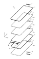
- FIG. 2 is a perspective view of a main part of the planar lighting device in an exploded state.
- FIG. 3 is a perspective view of the hole securing member, the fixing member, and the light-shielding / reinforcing sheet in individual states.
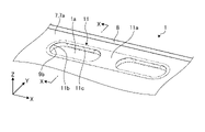
- FIG. 4 is an enlarged perspective view of the vicinity of the hole of the planar lighting device.
- FIG. 5 is a perspective view in which the vicinity of the hole 1a of the planar lighting device 1 is enlarged and a part thereof is shown in the XX cross section in FIG.
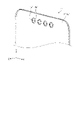
- FIG. 6 is a perspective view showing a bottom frame of the planar lighting device of the comparative example.
- planar lighting device according to the embodiment will be described with reference to the drawings.
- the present invention is not limited to this embodiment.
- the relationship between the dimensions of each element in the drawing, the ratio of each element, and the like may differ from the reality. Even between drawings, there may be parts with different dimensional relationships and ratios. Further, in principle, the contents described in one embodiment or modification are similarly applied to other embodiments or modifications.
- the direct type planar lighting device includes a light source substrate in which a plurality of light sources are arranged two-dimensionally (for example, in a grid pattern) and an optical sheet such as a diffusion sheet arranged on the emission surface side of the plurality of light sources. There is.
- FIG. 1 is a perspective view of the planar lighting device 1 according to the embodiment.
- the planar lighting device 1 has a substantially rectangular shape and a plate-like outer shape, the outer edge of which is surrounded by a frame-shaped frame 2, and a frame-shaped sheet-like shape on the exit surface side of the frame 2.
- a light-shielding sheet 8 is attached.
- the main surface 7a of the prism sheet 7 is exposed as the exit surface.
- Two holes 1a for mounting parts such as a camera are provided near one end of the exit surface, and the periphery thereof is covered with a set of light-shielding / reinforcing sheets 11.
- the number of holes 1a is not limited to two, and may be one or three or more.
- the hole 1a shown in the figure has a track shape in which the ends of two semi-arcs are connected by a straight line in a plan view, but the hole 1a is not limited to the shape of a circle, an ellipse, or a rectangle.
- the connecting portion 5a of the light source substrate 5 provided inside is pulled out from the side opposite to the side where the hole 1a is provided.
- FIG. 2 is a perspective view of the main part of the planar lighting device 1 in an exploded state.
- the planar illumination device 1 includes a frame 2, a reflection sheet 3, a light guide plate 4, a light source substrate 5, a diffusion sheet 6, a prism sheet 7, and a light-shielding sheet 8 as main members. It has a hole securing member 9, a fixing member 10, and a light-shielding / reinforcing sheet 11.
- the reflective sheet 3, the light guide plate 4, the diffusion sheet 6, and the prism sheet 7 are laminated and mounted inside the frame 2 (inside the frame).
- the light source substrate 5 is provided so that the light emitting side faces one side surface (light incident side surface) of the light guide plate 4.
- a bottom frame that covers the entire bottom surface and side surfaces of the planar lighting device 1 and a top frame that engages with the bottom frame and has an opening that serves as an emission surface are not provided.
- the frame 2 is a frame-shaped member and is made of resin or the like.
- the inner surface of the frame 2 is painted white or the like in order to enhance the reflectivity, or the frame 2 itself is formed of a white resin or the like.
- the reflective surface of the reflective sheet 3 faces the light guide plate 4, and the light efficiency is improved by reflecting and returning the light leaking from the light guide plate 4 to the reflective sheet 3.
- the reflective sheet 3 is provided with a flat main surface 3a and two openings 3b on which components such as a camera are mounted.
- the light guide plate 4 is made of a transparent resin or the like, receives light from the light source substrate 5 from the side of incoming light, propagates the light to the terminal side, and is an optical element such as a prism provided on the back surface (reflection sheet 3 side). Light is emitted to the surface side (diffusion sheet 6 side).
- the light guide plate 4 is provided with a flat main surface 4a and two openings 4b on which components such as a camera are mounted.
- a plurality of light sources such as LEDs (Light Emitting Diodes) are arranged in a row, and light is emitted toward one side surface (light entry side surface) of the light guide plate 4.
- the connection portion 5a is connected to a circuit portion (not shown).
- the diffusion sheet 6 diffuses the light emitted from the light guide plate 4 to make the brightness distribution uniform.
- the diffusion sheet 6 is provided with a flat main surface 6a and two openings 6b on which components such as a camera are mounted.
- the prism sheet 7 increases the amount of light in the normal direction and improves the brightness.
- the prism sheet 7 is provided with a flat main surface 7a and two openings 7b on which components such as a camera are mounted.
- the light-shielding sheet 8 has a frame shape or a sheet shape, and prevents light from leaking from the peripheral edges of the frame 2 and the prism sheet 7.
- the hole securing member 9, the fixing member 10, and the light-shielding / reinforcing sheet 11 will be described in detail below.
- FIG. 3 is a perspective view of the hole securing member 9, the fixing member 10, and the light-shielding / reinforcing sheet 11 in individual states.
- the hole securing member 9 has a flat flange portion 9a and a cylindrical protruding portion 9b.
- the protruding portion 9b is a portion that fits into the inner wall of the hole 1a (FIG. 1) on the exit surface with a predetermined clearance.
- the crossguard portion 9a is a portion that is connected to the protruding portion 9b as a base and faces a surface opposite to the exit surface side (reflection surface side) of the reflection sheet 3 as a part of the optical member.
- the fixing member 10 has a flat surface portion having substantially the same outer shape (corresponding to the flange portion 9a of the hole securing member 9) provided with an opening (second opening) 10b through which the protruding portion 9b of the hole securing member 9 is inserted. It has a second flat surface portion) 10a.
- the fixing member 10 is a double-sided tape, and adhesive layers are provided on the front surface and the back surface.
- the light-shielding / reinforcing sheet 11 has a flat surface portion 11a having substantially the same outer shape and an opening portion 11b corresponding to the flange portion 9a of the hole securing member 9 provided with the opening portion 11b corresponding to the protruding portion 9b of the hole securing member 9. It has a bent portion 11c that covers the inner wall of the protruding portion 9b of the hole securing member 9.
- FIG. 4 is an enlarged perspective view of the vicinity of the hole 1a of the planar lighting device 1.
- FIG. 5 is a perspective view in which the vicinity of the hole 1a of the planar lighting device 1 is enlarged and a part thereof is shown in the XX cross section in FIG.
- the protruding portion 9b of the hole securing member 9 is provided in the openings (10b, 3b, 4b, 6b, 7b) of the fixing member 10, the reflective sheet 3, the light guide plate 4, the diffusion sheet 6, and the prism sheet 7.
- a hole 1a penetrating in the thickness direction (Z-axis direction) is formed by fitting through a predetermined clearance and attaching the light-shielding / reinforcing sheet 11 from the exit surface side.
- the bent portion 11c of the light-shielding / reinforcing sheet 11 is fixed so as to cover the inner wall of the hole securing member 9 at the straight portion of the track-shaped hole 1a.
- the hole securing member 9 is stably fixed, and even if a component such as a camera is mounted in the hole 1a, the required strength can be satisfied.
- the inner wall of the hole securing member 9 may be covered and fixed by the bent portion 11c of the light-shielding / reinforcing sheet 11.
- FIG. 6 is a perspective view showing a bottom frame 2'of the planar lighting device 1'of the comparative example.
- An opening corresponding to the hole 1a' is also provided in the light guide plate and the optical sheet (not shown), and the light guide plate and the optical sheet are laminated on the bottom frame 2'so that the protrusion 2b'fits into the opening.
- the hole securing member 9 is not fixed to the metal bottom frame, and the reflective sheet 3, the light guide plate 4, the diffusion sheet 6 and the prism are exposed to temperature changes.
- the position moves together with the optical member by the sheet 7. Therefore, even if the distance between the parts between the hole securing member 9 and the optical member is reduced, wrinkles and twists do not occur, and the frame can be narrowed without affecting the optical characteristics.
- a distance between parts of 0.3 to 0.4 mm had to be provided, whereas in the embodiment of FIGS. 1 to 5, for example, a distance of 0.1 mm between parts is sufficient. It has been confirmed.
- the hole securing member 9 is made of a thin sheet metal or the like and is one size larger than the hole 1a, so that the weight is reduced.
- the hole securing member 9 is fixed by the bent portion 11c of the light-shielding / reinforcing sheet 11. Therefore, it is possible to prevent dropping and misalignment, and to secure the strength for supporting parts such as a camera.
- the planar illumination device includes an optical member having a hole penetrating a part of the exit surface, a hole securing member fixed to the hole from a surface opposite to the exit surface, and an exit surface.
- a light-shielding / reinforcing sheet that closes the circumference of the hole from the side is provided, and the hole securing member includes a tubular protruding portion that fits into the inner wall of the hole with a predetermined clearance and a surface that is connected to the protruding portion and is opposite to the exit surface of the optical member.
- the light-shielding / reinforcing sheet has a flange portion facing the crossguard, and the light-shielding / reinforcing sheet includes a flat portion corresponding to the collar portion in which an opening corresponding to the protrusion is provided, and a bent portion which is connected to the opening and covers the inner wall of the protrusion.
- the frame can be narrowed, and the strength for supporting the component can be secured. That is, since the hole securing member moves together with the optical member in response to a temperature change, wrinkles and twists do not occur even if the distance between the parts is reduced between the hole securing member and the optical member, which affects the optical characteristics.
- the frame can be narrowed without any problem. Further, since the hole securing member is fixed by the bent portion of the light-shielding / reinforcing sheet, it is possible to secure the strength for supporting the parts.
- the collar portion has a second flat portion corresponding to the collar portion to which the second opening through which the protrusion portion is inserted is provided, and includes a fixing member for fixing the collar portion to the surface opposite to the exit surface of the optical member. ..
- a fixing member for fixing the collar portion to the surface opposite to the exit surface of the optical member.
- the hole is track-shaped, and the bent part is provided in the straight part of the track shape. As a result, fixing by the bent portion can be stably performed.
- the optical member includes a light guide plate and an optical sheet constituting an edge light type planar illumination device, or a light source substrate and an optical sheet constituting a direct type planar illumination device. As a result, it can be applied to various planar lighting devices.
- a plurality of holes are formed side by side on the exit surface, and one set of a hole securing member and a light-shielding / reinforcing sheet is provided for the plurality of holes.
- the present invention is not limited by the above-described embodiment.
- the present invention also includes a configuration in which the above-mentioned components are appropriately combined. Further, further effects and modifications can be easily derived by those skilled in the art. Therefore, the broader aspect of the present invention is not limited to the above-described embodiment, and various modifications can be made.
- 1 planar lighting device 1a hole, 2 frame, 3 reflective sheet, 4 light guide plate, 5 light source board, 6 diffusion sheet, 7 prism sheet, 8 light-shielding sheet, 9 hole securing member, 9a crossguard, 9b protrusion, 10 Fixing member, 10a flat surface, 10b opening, 11 light-shielding / reinforcing sheet, 11a flat surface, 11b opening, 11c bent part
Landscapes
- Physics & Mathematics (AREA)
- General Physics & Mathematics (AREA)
- Optics & Photonics (AREA)
- Nonlinear Science (AREA)
- Mathematical Physics (AREA)
- Chemical & Material Sciences (AREA)
- Crystallography & Structural Chemistry (AREA)
- Engineering & Computer Science (AREA)
- General Engineering & Computer Science (AREA)
- Planar Illumination Modules (AREA)
- Liquid Crystal (AREA)
Abstract
実施形態の面状照明装置(1)は、光学部材(3、4、6、7)と、穴確保部材(9)と、遮光・補強シート(11)とを備える。前記光学部材(3、4、6、7)は、出射面の一部に貫通した穴(1a)を有する。前記穴確保部材(9)は、前記出射面と反対側の面から前記穴(1a)に固定され、前記穴(1a)の内壁に所定のクリアランスをもって嵌る筒状の突出部(9b)と、該突出部(9b)に連なり前記光学部材(3、4、6、7)の前記出射面と反対側の面に対向する鍔部(9a)とを有する。前記遮光・補強シート(11)は、前記出射面側から前記穴(1a)の周囲を塞ぎ、前記突出部(9b)に対応する開口部(11b)が設けられる、前記鍔部(9a)に対応する平面部(11a)と、前記開口部(11b)に連なり前記突出部(9b)の内壁を覆う折曲部(11c)とを有する。
Description
本発明は、面状照明装置に関する。
スマートフォン等の表示面として、デザイン的な観点から額縁部が極めて小さいフルスクリーンが要望されており、カメラ等の部品がスクリーン内に設けられた穴に配置されるタイプの装置が存在する(例えば、特許文献1~3等を参照)。このような装置では、液晶パネルのバックライトとして用いられる面状照明装置にも、発光面にカメラ等の部品の装着用の貫通した穴が設けられた構造が要求される。
発光面に貫通した穴が設けられた構造の面状照明装置として、導光板および光学シートが載置される金属フレームに一体に形成された煙突状・筒状の突出部により穴が構成される場合(例えば、特許文献1)があった。また、導光板に単純に穴が設けられる場合(例えば、特許文献2)や、導光板および光学シートの穴がリングで塞がれる場合(例えば、特許文献3)等があった。
しかしながら、金属フレームに一体に形成された煙突状・筒状の突出部により穴が構成される場合は、カメラ等の部品を支持するための強度は充分に保たれ、遮光性も高いが、金属材料と導光板や光学シートの樹脂材料との熱膨張率の違いによる伸縮の差により、穴部分や外縁部分の狭額縁化が困難になる問題があった。すなわち、突出部と金属フレームの側壁との間に挟まれる導光板や光学シートの部分の温度変化に対する伸縮を吸収するために部品間距離(クリアランス)を適切に確保しないとシワやヨレが発生し、光学特性に影響を与えてしまうため、十分な距離を確保する必要があった。その結果、充分な狭額縁化が図れなかった。
また、導光板に単純に穴が設けられる場合や、導光板および光学シートの穴がリングで塞がれる場合は、カメラ等の部品を支える強度が低下したり、遮光が不十分となったりする問題があった。遮光としては、導光板や光学シートからカメラ等の部品に不要な光を漏らさないことが重要となる。
本発明は、上記に鑑みてなされたものであって、光学特性を維持でき、狭額縁化が図れ、部品を支持するための強度を確保することができる面状照明装置を提供することを目的とする。
上述した課題を解決し、目的を達成するために、本発明の一態様に係る面状照明装置は、光学部材と、穴確保部材と、遮光・補強シートとを備える。前記光学部材は、出射面の一部に貫通した穴を有する。前記穴確保部材は、前記出射面と反対側の面から前記穴に固定され、前記穴の内壁に所定のクリアランスをもって嵌る筒状の突出部と、該突出部に連なり前記光学部材の前記出射面と反対側の面に対向する鍔部とを有する。前記遮光・補強シートは、前記出射面側から前記穴の周囲を塞ぎ、前記突出部に対応する開口部が設けられる、前記鍔部に対応する平面部と、前記開口部に連なり前記突出部の内壁を覆う折曲部とを有する。
本発明の一態様に係る面状照明装置は、光学特性を維持でき、狭額縁化が図れ、部品を支持するための強度を確保することができる。
以下、実施形態に係る面状照明装置について図面を参照して説明する。なお、この実施形態によりこの発明が限定されるものではない。また、図面における各要素の寸法の関係、各要素の比率などは、現実と異なる場合がある。図面の相互間においても、互いの寸法の関係や比率が異なる部分が含まれている場合がある。また、1つの実施形態や変形例に記載された内容は、原則として他の実施形態や変形例にも同様に適用される。
以下では、いわゆるエッジライト型の面状照明装置について説明するが、いわゆる直下型の面状照明装置にも同様に適用することができる。直下型の面状照明装置は、2次元(例えば、格子状)に複数の光源が配置された光源基板と、複数の光源の出射面側に配置された拡散シート等の光学シートとを備えている。
図1は、一実施形態にかかる面状照明装置1の斜視図である。図1において、面状照明装置1は、略矩形状で板状の外形を有しており、外縁が枠状のフレーム2で囲まれ、フレーム2の出射面側には枠状でシート状の遮光シート8が貼り付けられている。出射面として、プリズムシート7の主面7aが露出している。
出射面の一方の端部付近には、カメラ等の部品が装着される2個の穴1aが設けられており、その周囲は1組の遮光・補強シート11により覆われている。なお、穴1aの個数は2個に限られず、1個でもよいし、3個以上でもよい。図示の穴1aは、平面視で2つの半円弧の端部が直線で接続されたトラック形状のものとなっているが、それに限らず、円形状や楕円形状や矩形状であってもよい。また、穴1aが設けられた辺と反対側の辺からは、内部に設けられた光源基板5の接続部5aが引き出されている。
図2は、面状照明装置1の主要部を分解した状態の斜視図である。図2において、面状照明装置1は、主要な部材として、フレーム2と、反射シート3と、導光板4と、光源基板5と、拡散シート6と、プリズムシート7と、遮光シート8と、穴確保部材9と、固定部材10と、遮光・補強シート11とを有している。反射シート3、導光板4、拡散シート6およびプリズムシート7は積層されてフレーム2の内側(枠内)に装着される。光源基板5は、導光板4の一の側面(入光側面)に発光側が対向して設けられる。なお、面状照明装置1の全体の底面および側面を覆うボトムフレームや、ボトムフレームに係合し、出射面となる開口部を有するトップフレームは設けられていない。
フレーム2は、枠状の部材であり、樹脂等により構成される。フレーム2の内側の面は反射性を高めるために白色等に塗装されるか、フレーム2自体が白色の樹脂等により形成されている。反射シート3は、反射面が導光板4側を向いており、導光板4から反射シート3側に漏れる光を反射して戻すことにより、光効率を向上させる。反射シート3には、平面状の主面3aと、カメラ等の部品が装着される2個の開口部3bとが設けられている。
導光板4は、透明な樹脂等により構成され、光源基板5からの光を入光側面から受け入れ、光を終端側まで伝搬させ、裏面(反射シート3側)に設けられたプリズム等の光学素子により表面側(拡散シート6側)に光を出射する。導光板4には、平面状の主面4aと、カメラ等の部品が装着される2個の開口部4bとが設けられている。
光源基板5は、複数のLED(Light Emitting Diode)等の光源が1列に配置されており、導光板4の一の側面(入光側面)に向けて光を出射する。接続部5aは図示しない回路部に接続される。拡散シート6は、導光板4から出射された光を拡散し、輝度分布を均一化する。拡散シート6には、平面状の主面6aと、カメラ等の部品が装着される2個の開口部6bとが設けられている。
プリズムシート7は、法線方向の光の量を増やし、輝度を向上させる。プリズムシート7には、平面状の主面7aと、カメラ等の部品が装着される2個の開口部7bとが設けられている。遮光シート8は、枠状・シート状であり、フレーム2とプリズムシート7の周縁からの光の漏れを防ぐ。
穴確保部材9、固定部材10および遮光・補強シート11については、以下、詳細に説明する。
図3は、穴確保部材9、固定部材10および遮光・補強シート11の個別の状態における斜視図である。図3において、穴確保部材9は、平面状の鍔部9aと、筒状の突出部9bとを有している。突出部9bは、出射面の穴1a(図1)の内壁に所定のクリアランスをもって嵌る部分である。鍔部9aは、突出部9bに基台として連なり、光学部材の一部としての反射シート3の出射面側(反射面側)と反対側の面に対向する部分である。
固定部材10は、穴確保部材9の突出部9bが挿通する開口部(第2の開口部)10bが設けられた、穴確保部材9の鍔部9aに対応する、ほぼ同じ外形の平面部(第2の平面部)10aを有している。固定部材10は、両面テープとなっており、表面および裏面に接着層が設けられている。
遮光・補強シート11は、穴確保部材9の突出部9bに対応する開口部11bが設けられた、穴確保部材9の鍔部9aに対応する、ほぼ同じ外形の平面部11aと、開口部11bに連なり穴確保部材9の突出部9bの内壁を覆う折曲部11cとを有している。
図4は、面状照明装置1の穴1aの付近を拡大した斜視図である。図5は、面状照明装置1の穴1aの付近を拡大して一部を図4中のX-X断面で示した斜視図である。図4および図5において、固定部材10、反射シート3、導光板4、拡散シート6およびプリズムシート7の開口部(10b、3b、4b、6b、7b)に穴確保部材9の突出部9bが所定のクリアランスを介して嵌り、出射面側から遮光・補強シート11が貼り付けられることで厚さ方向(Z軸方向)に貫通する穴1aが形成されている。
遮光・補強シート11の折曲部11cは、トラック形状の穴1aの直線部分において、穴確保部材9の内壁が覆されるように固定されている。これにより、穴確保部材9は安定して固定されることとなり、カメラ等の部品が穴1aに装着されても要求される強度を満たすことができる。なお、穴1aの円弧部分においても、遮光・補強シート11の折曲部11cにより穴確保部材9の内壁が覆われて固定されるようにしてもよい。
図6は、比較例の面状照明装置1’のボトムフレーム2’を示す斜視図である。図6において、金属製のボトムフレーム2’の底面には、絞り加工等によって煙突状・円筒状の突出部2b’が複数形成されており、複数の穴1a’を形成している。図示しない導光板や光学シートにも穴1a’に対応した開口部が設けられ、その開口部に突出部2b’が嵌るようにして、ボトムフレーム2’の上に導光板や光学シートが積層される。
そのため、突出部2b’とボトムフレーム2’の側壁との間に挟まれる導光板や光学シートの部分は、金属と樹脂等との熱膨張率の違いによる伸縮の差によりシワやヨレが発生しないように、大きめの部品間距離(クリアランス)を確保しなければならず、充分な狭額縁化が図れなかった。
その点、図1~図5の実施形態では、穴確保部材9は金属製のボトムフレームには固定されておらず、温度変化に対して、反射シート3、導光板4、拡散シート6およびプリズムシート7による光学部材とともに位置が移動する。そのため、穴確保部材9と光学部材との間の部品間距離を小さくしてもシワやヨレが発生せず、光学特性に影響を与えることなく狭額縁化が図れる。図6の比較例では、例えば0.3~0.4mmの部品間距離を設けなければならなかったのに対し、図1~図5の実施形態では、例えば0.1mmの部品間距離で済むことが確認されている。
また、穴確保部材9は薄い板金等により構成され、穴1aよりも一回り大きい程度のサイズであるため軽量化であり、遮光・補強シート11の折曲部11cにより穴確保部材9が固定されるため、脱落や位置ズレが防止され、カメラ等の部品を支持するための強度を確保することができる。
以上、本発明の実施形態について説明したが、本発明は上記実施形態に限定されるものではなく、その趣旨を逸脱しない限りにおいて種々の変更が可能である。
以上のように、実施形態に係る面状照明装置は、出射面の一部に貫通した穴を有する光学部材と、出射面と反対側の面から穴に固定される穴確保部材と、出射面側から穴の周囲を塞ぐ遮光・補強シートとを備え、穴確保部材は、穴の内壁に所定のクリアランスをもって嵌る筒状の突出部と、突出部に連なり光学部材の出射面と反対側の面に対向する鍔部とを有し、遮光・補強シートは、突出部に対応する開口部が設けられる、鍔部に対応する平面部と、開口部に連なり突出部の内壁を覆う折曲部とを有する。これにより、光学特性を維持でき、狭額縁化が図れ、部品を支持するための強度を確保することができる。すなわち、穴確保部材は温度変化に対して光学部材とともに移動するため、穴確保部材と光学部材との間の部品間距離を小さくしてもシワやヨレが発生せず、光学特性に影響を与えることなく狭額縁化が図れる。また、遮光・補強シートの折曲部により穴確保部材が固定されるため、部品を支持するための強度を確保することができる。
また、突出部が挿通する第2の開口部が設けられる、鍔部に対応する第2の平面部を有し、鍔部を光学部材の出射面と反対側の面に固定する固定部材を備える。これにより、いっそう部品を支持するための強度を確保することができる。
また、穴はトラック形状であり、折曲部は、トラック形状の直線部分に設けられる。これにより、折曲部による固定を安定に行うことができる。
また、光学部材は、エッジライト型の面状照明装置を構成する導光板および光学シート、または、直下型の面状照明装置を構成する光源基板および光学シートを含む。これにより、多様な面状照明装置に適用することができる。
また、出射面に複数の穴が並んで形成され、穴確保部材および遮光・補強シートは、複数の穴に対して1組が設けられる。これにより、多様なカメラ等の部品の装着に容易に対応することができる。
また、上記実施の形態により本発明が限定されるものではない。上述した各構成要素を適宜組み合わせて構成したものも本発明に含まれる。また、さらなる効果や変形例は、当業者によって容易に導き出すことができる。よって、本発明のより広範な態様は、上記の実施の形態に限定されるものではなく、様々な変更が可能である。
1 面状照明装置,1a 穴,2 フレーム,3 反射シート,4 導光板,5 光源基板,6 拡散シート,7 プリズムシート,8 遮光シート,9 穴確保部材,9a 鍔部,9b 突出部,10 固定部材,10a 平面部,10b 開口部,11 遮光・補強シート,11a 平面部,11b 開口部,11c 折曲部
Claims (5)
- 出射面の一部に貫通した穴を有する光学部材と、
前記出射面と反対側の面から前記穴に固定される穴確保部材と、
前記出射面側から前記穴の周囲を塞ぐ遮光・補強シートと、
を備え、
前記穴確保部材は、前記穴の内壁に所定のクリアランスをもって嵌る筒状の突出部と、該突出部に連なり前記光学部材の前記出射面と反対側の面に対向する鍔部とを有し、
前記遮光・補強シートは、前記突出部に対応する開口部が設けられる、前記鍔部に対応する平面部と、前記開口部に連なり前記突出部の内壁を覆う折曲部とを有する、
面状照明装置。 - 前記突出部が挿通する第2の開口部が設けられる、前記鍔部に対応する第2の平面部を有し、前記鍔部を前記光学部材の前記出射面と反対側の面に固定する固定部材を備える、
請求項1に記載の面状照明装置。 - 前記穴はトラック形状であり、前記折曲部は、トラック形状の直線部分に設けられる、
請求項1または2に記載の面状照明装置。 - 前記光学部材は、エッジライト型の面状照明装置を構成する導光板および光学シート、または、直下型の面状照明装置を構成する光源基板および光学シートを含む、
請求項1~3のいずれか一つに記載の面状照明装置。 - 前記出射面に複数の前記穴が並んで形成され、前記穴確保部材および前記遮光・補強シートは、複数の前記穴に対して1組が設けられる、
請求項1~4のいずれか一つに記載の面状照明装置。
Applications Claiming Priority (2)
| Application Number | Priority Date | Filing Date | Title |
|---|---|---|---|
| JP2021005947A JP2022110490A (ja) | 2021-01-18 | 2021-01-18 | 面状照明装置 |
| JP2021-005947 | 2021-01-18 |
Publications (1)
| Publication Number | Publication Date |
|---|---|
| WO2022153649A1 true WO2022153649A1 (ja) | 2022-07-21 |
Family
ID=82447111
Family Applications (1)
| Application Number | Title | Priority Date | Filing Date |
|---|---|---|---|
| PCT/JP2021/040448 Ceased WO2022153649A1 (ja) | 2021-01-18 | 2021-11-02 | 面状照明装置 |
Country Status (2)
| Country | Link |
|---|---|
| JP (1) | JP2022110490A (ja) |
| WO (1) | WO2022153649A1 (ja) |
Citations (4)
| Publication number | Priority date | Publication date | Assignee | Title |
|---|---|---|---|---|
| CN109785744A (zh) * | 2018-12-25 | 2019-05-21 | 友达光电(昆山)有限公司 | 显示装置及使用该显示装置的终端 |
| JP2019215415A (ja) * | 2018-06-12 | 2019-12-19 | 株式会社ジャパンディスプレイ | 表示装置及び電子機器 |
| JP2020047455A (ja) * | 2018-09-19 | 2020-03-26 | ミネベアミツミ株式会社 | 面状照明装置 |
| JP2020071998A (ja) * | 2018-10-31 | 2020-05-07 | ミネベアミツミ株式会社 | 面状照明装置 |
-
2021
- 2021-01-18 JP JP2021005947A patent/JP2022110490A/ja active Pending
- 2021-11-02 WO PCT/JP2021/040448 patent/WO2022153649A1/ja not_active Ceased
Patent Citations (4)
| Publication number | Priority date | Publication date | Assignee | Title |
|---|---|---|---|---|
| JP2019215415A (ja) * | 2018-06-12 | 2019-12-19 | 株式会社ジャパンディスプレイ | 表示装置及び電子機器 |
| JP2020047455A (ja) * | 2018-09-19 | 2020-03-26 | ミネベアミツミ株式会社 | 面状照明装置 |
| JP2020071998A (ja) * | 2018-10-31 | 2020-05-07 | ミネベアミツミ株式会社 | 面状照明装置 |
| CN109785744A (zh) * | 2018-12-25 | 2019-05-21 | 友达光电(昆山)有限公司 | 显示装置及使用该显示装置的终端 |
Also Published As
| Publication number | Publication date |
|---|---|
| JP2022110490A (ja) | 2022-07-29 |
Similar Documents
| Publication | Publication Date | Title |
|---|---|---|
| JP4970177B2 (ja) | 面発光装置及び表示装置 | |
| US8797475B2 (en) | Lighting device, display device and television receiver | |
| CN102052606A (zh) | 背光单元和包括该背光单元的显示设备 | |
| JP5848631B2 (ja) | 照明装置およびそれを備えた表示装置 | |
| JP2019185921A (ja) | 照明装置及びそれを備えた表示装置 | |
| US20200133050A1 (en) | Display device | |
| CN110275350A (zh) | 照明装置及具备其的显示装置 | |
| JP7108897B2 (ja) | 画像表示装置 | |
| US10168468B2 (en) | Illumination device and display device | |
| JP2000132113A (ja) | 導光板 | |
| JP2011029045A (ja) | 光源装置および表示装置 | |
| TW201020650A (en) | A backlight module and a flat display using the backlight module | |
| US20210080784A1 (en) | Display device | |
| TW202024730A (zh) | 背光模組 | |
| JP6812608B2 (ja) | 面状照明装置 | |
| JP2005285535A (ja) | 照明ユニット及びこれを用いた液晶表示装置 | |
| JP4780216B2 (ja) | 面光源装置とその製造方法、及び画像表示装置 | |
| JP2018181630A (ja) | バックライト | |
| CN101285963A (zh) | 背光模块 | |
| WO2013024896A1 (ja) | 照明装置およびそれを備えた表示装置 | |
| WO2022153649A1 (ja) | 面状照明装置 | |
| WO2019184412A1 (zh) | 背光模组及液晶显示装置 | |
| JP6889816B1 (ja) | 面状照明装置 | |
| JP5665623B2 (ja) | 面状ライトユニット | |
| CN108153060A (zh) | 背光模组、显示装置和电子设备 |
Legal Events
| Date | Code | Title | Description |
|---|---|---|---|
| 121 | Ep: the epo has been informed by wipo that ep was designated in this application |
Ref document number: 21919540 Country of ref document: EP Kind code of ref document: A1 |
|
| NENP | Non-entry into the national phase |
Ref country code: DE |
|
| 122 | Ep: pct application non-entry in european phase |
Ref document number: 21919540 Country of ref document: EP Kind code of ref document: A1 |