WO2022153378A1 - 冷蔵庫 - Google Patents
冷蔵庫 Download PDFInfo
- Publication number
- WO2022153378A1 WO2022153378A1 PCT/JP2021/000771 JP2021000771W WO2022153378A1 WO 2022153378 A1 WO2022153378 A1 WO 2022153378A1 JP 2021000771 W JP2021000771 W JP 2021000771W WO 2022153378 A1 WO2022153378 A1 WO 2022153378A1
- Authority
- WO
- WIPO (PCT)
- Prior art keywords
- top plate
- box body
- sheet metal
- refrigerator
- reinforcing sheet
- Prior art date
- Legal status (The legal status is an assumption and is not a legal conclusion. Google has not performed a legal analysis and makes no representation as to the accuracy of the status listed.)
- Ceased
Links
Images









Classifications
-
- F—MECHANICAL ENGINEERING; LIGHTING; HEATING; WEAPONS; BLASTING
- F25—REFRIGERATION OR COOLING; COMBINED HEATING AND REFRIGERATION SYSTEMS; HEAT PUMP SYSTEMS; MANUFACTURE OR STORAGE OF ICE; LIQUEFACTION SOLIDIFICATION OF GASES
- F25D—REFRIGERATORS; COLD ROOMS; ICE-BOXES; COOLING OR FREEZING APPARATUS NOT OTHERWISE PROVIDED FOR
- F25D23/00—General constructional features
- F25D23/06—Walls
Definitions
- This disclosure relates to the structure of the upper surface of the refrigerator.
- a top plate is attached to the upper surface of the box body, and the top plate can be used as a storage space such as a microwave oven or a work space for pouring water into a cup.
- a storage space such as a microwave oven or a work space for pouring water into a cup.
- the top plate is extended from the upper surface of the box body to the upper surface of the door (see, for example, Patent Document 1).
- the top plate is reinforced by attaching side member to each of the left and right ends of the top plate.
- the present disclosure has been made to solve the above problems, and an object of the present disclosure is to provide a refrigerator in which the number of parts and the deformation of the top plate are suppressed while taking a large space on the top plate.
- the refrigerator according to the present disclosure includes a box having a front opening, a door attached to the box to open and close the front opening, and at least a part of the upper surface of the box and at least a part of the upper surface of the door. It was mounted so as to cover a top plate having a first claw extending rearward from the lower side of the front end, and at least a part of the front upper surface of the box and at least a part of the upper surface of the door. A reinforcing sheet metal is provided, and the reinforcing sheet metal is attached to the top plate in a state where the front end portion is fitted with the first claw of the top plate.
- the top plate is attached to the upper surface of the box body so as to cover at least a part of the upper surface of the box body and at least a part of the upper surface of the door, a space on the top plate is created. Can be taken widely. Further, since the top plate is reinforced with one reinforcing sheet metal, the number of parts can be suppressed. Further, since the reinforcing sheet metal is attached so as to cover at least a part of the front upper surface of the box body and at least a part of the upper surface of the door, the strength of not only the side portion of the top plate but also the central portion can be increased. , Deformation of the top plate can be suppressed.
- FIG. 4 is a cross-sectional view taken along the line AA of FIG.
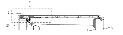
- FIG. 5 is an enlarged view of part B in FIG.
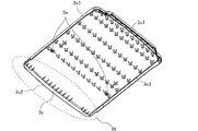
- It is a perspective view which looked at the top plate of the refrigerator which concerns on Embodiment 1 from above.
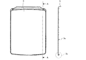
- FIG. 1 It is a plan view of the top plate of the refrigerator which concerns on Embodiment 1, and is the cross-sectional view of AA. It is a perspective view of the upper part which looked at the state which removed the top plate of the refrigerator which concerns on Embodiment 1 from above. It is a perspective view which looked at the attachment of the refrigerator which concerns on Embodiment 1 from above. It is a perspective view which shows the state of attaching the reinforcing sheet metal to the upper part of the refrigerator which concerns on Embodiment 1.
- FIG. It is a vertical sectional view in the depth direction when the reinforcing sheet metal is attached to the upper part of the refrigerator which concerns on Embodiment 1.
- FIG. 19 is a cross-sectional view taken along the line CC of FIG.
- FIG. 1 is a front view of the refrigerator 100 according to the first embodiment.
- FIG. 2 is a perspective view of the refrigerator 100 according to the first embodiment as viewed from above.
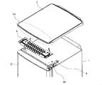
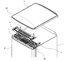
- FIG. 3 is an exploded perspective view of the upper part of the refrigerator 100 according to the first embodiment as viewed from above.
- FIG. 4 is an enlarged side view of the upper part of the refrigerator 100 according to the first embodiment.
- FIG. 5 is a cross-sectional view taken along the line AA of FIG.
- FIG. 6 is an enlarged view of part B of FIG.
- each component of the refrigerator 100 in the following description for example, the positional relationship such as up / down, left / right, front / back, outside / inside, front / back, or vertical / horizontal, is installed in a state where the refrigerator 100 can be used in principle. It is the positional relationship when it is done.
- the dimensional relationship and shape of each constituent member may differ from the actual ones.
- the same members or parts or members or parts having the same functions are designated by the same reference numerals or omitted.
- the refrigerator 100 has a box body 1 having a front opening (not shown) and a plurality of doors 2 covering the front opening of the box body 1.
- the box body 1 and the door 2 form an outer shell of the refrigerator 100.
- a refrigerator 100 having two doors 2 with the upper tier as the refrigerating chamber 10a and the lower tier as the freezing chamber 10b will be described as an example.
- a top plate 3 is provided on the upper surface of the box body 1.
- the box body 1 is a heat-insulating housing capable of accommodating stored items such as food inside the box body 1. Further, as shown in FIG. 5, the box body 1 includes an outer box 1b forming the outer shell of the refrigerator 100 and an inner box 1a forming the inner space of the refrigerator 100.
- the outer box 1b is made of a steel plate such as stainless steel.
- the inner box 1a is made of a synthetic resin such as plastic. Further, the outer box 1b and the inner box 1a are filled with a heat insulating material 8 having a heat insulating property such as a vacuum heat insulating material or a urethane resin.
- the box body 1 has one or more heat insulating partition walls (not shown).
- the partition wall divides the internal space of the inner box 1a into one or more storage chambers (not shown) having different temperature zones.
- the inside of the partition wall is filled with a heat insulating material (not shown) having heat insulating properties such as a vacuum heat insulating material or urethane resin so that heat conduction does not occur between adjacent storage chambers via the partition wall.
- a heat insulating material not shown
- the storage room can be used as a freezer room 10b and a refrigerating room 10a having different cold storage temperatures.
- the door 2 opens or seals the internal space of the box 1.
- the door 2 is attached to the box body 1 so that the front opening can be opened and closed.
- the design surface 2a of the door 2 that is, the front surface and the peripheral surface, is made of glass or sheet metal.
- the back surface of the door 2 is made of a synthetic resin such as plastic.
- the space between the design surface 2a of the door 2 and the back surface is filled with a heat insulating material 8 having a heat insulating property such as a vacuum heat insulating material or urethane resin.
- the door 2 has a number of doors 2 corresponding to the storage chamber of the refrigerator 100.
- the refrigerator 100 is provided with two doors, that is, a refrigerator compartment door 21 and a freezer compartment door 22.
- the refrigerator compartment door 21 is attached to the box body 1 via a hinge 30.
- the hinge 30 connects the box body 1 and the refrigerator compartment door 21, and rotates the refrigerator compartment door 21.
- the refrigerating room door 21 is formed as a rotary double door having a left door and a right door
- the left door and the right door are passed through the left door hinge and the right door hinge, respectively, to form the box body 1.
- It is attached to the top of the door.
- an attachment 5 for fixing the hinge 30 and the top plate 3 is provided on the upper surface of the box body 1, and a clamp 4 for fixing the top plate 3 is provided on the attachment 5. .
- the refrigerator chamber 10a has one door 2 as shown in FIGS. 1 and 2.
- a top plate 3 is provided on the upper surface of the box body 1 and covers the upper surface of the box body 1 of the refrigerator 100 and the hinge 30.
- the top plate 3 is formed of heat-resistant resin, and has a structure in which the upper surface of the box 1 can be used as a storage space for a microwave oven or the like, or as a work space for pouring water into a cup.
- FIG. 7 is a perspective view of the top plate 3 of the refrigerator 100 according to the first embodiment as viewed from above.
- FIG. 8 is a perspective view of the top plate 3 of the refrigerator 100 according to the first embodiment as viewed from below.
- FIG. 9 is a plan view of the top plate 3 of the refrigerator 100 according to the first embodiment and a cross-sectional view taken along the line AA.
- FIG. 10 is a perspective view of the upper part of the refrigerator 100 according to the first embodiment, in which the top plate 3 is removed, as viewed from above.
- FIG. 11 is a perspective view of the attachment 5 of the refrigerator 100 according to the first embodiment as viewed from above.
- the top plate 3 covers the upper surface of the box body 1 of the refrigerator 100 and the upper surface of the door 2, and forms the upper surface of the refrigerator 100 on the surface 3c1 and above the door 2 of the refrigerator 100.
- the top plate 3 does not have to cover all of the upper surface of the box 1 and the upper surface of the door 2, and may cover most of the upper surface of the box 1 and most of the upper surface of the door 2. ..
- the portion covering the upper surface of the door 2 is referred to as the eaves portion 3d.
- a large first claw 3c of several cm from the front end portion toward the rear is provided over the entire width of the eaves portion 3d, and on the lower surface of the top plate 3, a first claw 3c is provided.
- Two claws 3a are provided on the left and right respectively.
- the top plate 3 is fixed to the back surface of the box body 1 of the refrigerator 100 by screws, and as shown in FIG. 6, the front surface side of the top plate 3 is attached to the clamp 4 of the attachment 5 attached to the upper surface of the box body 1. It is fixed by fitting the second claw 3a on the lower surface.
- the top plate has a size that covers only the upper surface of the box body.
- the top plate 3 according to the first embodiment has a size that covers not only the upper surface of the box 1 but also the upper surface of the refrigerating room door 21, so that a flat surface on the upper surface is wider than that of the conventional refrigerator. Therefore, a large space on the top plate 3 can be taken.
- the hinge since the hinge is screwed to the upper surface of the box body, an attachment made of sheet metal is attached to the inside of the upper surface of the outer box forming the outer shell of the box body.
- the attachment 5 for screwing the hinge 30 to the upper surface of the box 1 is configured to be wider than before, and the attachment 5 is common to the hinge 30 and the top plate 3. It is a sheet metal for fixing.
- the attachment 5 is provided with an L-shaped clamp 4 for fixing the top plate 3 when viewed from the side.
- the clamp 4 is formed by cutting and raising a sheet metal, and has a plate-shaped wall portion 32 protruding upward and a locking portion 33 extending forward from the tip of the wall portion 32 to lock the top plate 3 in the vertical direction. It is composed of and more.
- FIG. 6 when the attachment 5 is fixed to the hinge 30 via the outer box 1b with a screw 31, the clamp 4 is provided on the attachment 5 which is a sheet metal so that the clamp 4 projects toward the hinge 30. ing.
- the clamp 4 is configured to project from the upper surface opening 1c formed on the upper surface of the outer box 1b toward the upper surface side of the box body 1.
- the attachment 5 when the attachment 5 is attached to the attachment 5 from the inside of the outer box 1b, it is fitted into an opening (not shown) formed on the upper surface of the outer box 1b.
- the protrusion 35 for positioning is formed so as to protrude upward.
- the attachment 5 is formed with a screw hole 34 for fixing the attachment 5 with a screw 31 to the hinge 30 and the outer box 1b.
- the attachment 5 as a common fixing sheet metal for the hinge 30 and the top plate 3, it is not necessary to separately prepare an attachment for fixing the top plate 3 to the upper surface of the box body 1.
- a heat insulating material 8 having a heat insulating property such as a vacuum heat insulating material or a urethane resin.
- the attachment 5 is pressed against the outer box 1b by the pressure of the heat insulating material 8. Therefore, since the attachment 5 is stably fixed to the outer box 1b, it is not necessary to screw the attachment 5 in the vicinity of the upper surface opening 1c to prevent misalignment, and the work process can be simplified.
- the clamp 4 is located in front of the center of the upper surface of the box body 1 in the depth direction, and is provided at one position on each of the left and right sides. Further, by sliding the top plate 3 from the front to the rear with respect to the clamp 4, the second claw 3a is fitted to the clamp 4. Then, in a state where the second claw 3a and the clamp 4 are fitted, the top plate 3 is fixed to the back surface of the box body 1 with screws, so that the top plate 3 is fixed to the upper surface of the box body 1.
- the structure is such that the top plate 3 can be fixed to the box 1 by fixing the top plate 3 only to the back surface of the box 1, so that the work process can be simplified.
- an edge 3b is provided on the upper surface of the top plate 3 so as to project upward by about 1 mm along the outer circumference.
- FIG. 12 is a perspective view showing how the reinforcing sheet metal 6 is attached to the upper part of the refrigerator 100 according to the first embodiment.
- FIG. 13 is a vertical cross-sectional view in the depth direction when the reinforcing sheet metal 6 is attached to the upper portion of the refrigerator 100 according to the first embodiment.
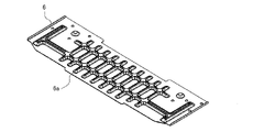
- FIG. 14 is a perspective view of the reinforcing sheet metal 6 of the refrigerator 100 according to the first embodiment as viewed from above.
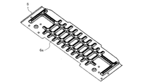
- FIG. 15 is a perspective view of the reinforcing sheet metal 6 of the refrigerator 100 according to the first embodiment as viewed from below.
- the force applied to the upper surface of the box body 1 is received on the box body 1 side, so that the heavens It is possible to prevent deformation of parts such as the plate 3.
- the force applied to the eaves 3d formed by extending the front of the top plate 3 to the upper surface of the door 2 cannot be received by the box body 1, and the upper surface of the door 2 should not come into contact with the top plate 3. It is lower than the top plate 3 and cannot be received by the door 2. Therefore, when a force is applied to the eaves portion 3d, the top plate 3 may be deformed.
- a reinforcing sheet metal 6 is attached between the top plate 3 and the box body 1 to increase the strength of the eaves portion 3d.
- the reinforcing sheet metal 6 is attached between the box body 1 and the top plate 3.
- the reinforcing sheet metal 6 is made of a sheet metal having a thickness of 1.0 mm, with a strength that can withstand even if five 2 L PET bottles are placed, and a thickness that does not deform even when a weight of 10 kg is applied as a target value.
- the thickness of the reinforcing sheet metal 6 may be increased according to the magnitude of the force applied to the assumed top plate 3.
- the reinforcing sheet metal 6 is fixed to the upper surface of the box body 1 with screws or double-sided tape before the top plate 3 is attached to the box body 1. At this time, the reinforcing sheet metal 6 is fixed so as to cover the front upper surface of the box body 1 and the upper surface of the door 2.
- the reinforcing sheet metal 6 does not have to cover all of the front upper surface of the box 1 and the upper surface of the door 2, as long as it covers most of the front upper surface of the box 1 and most of the upper surface of the door 2. It often has a shape that fits inside the top plate 3 when the refrigerator 100 is viewed from above.
- the strength of not only the side portion but also the central portion of the top plate 3 can be increased, so that the deformation of the top plate 3 when a force is applied to the eaves portion 3d can be suppressed. ..
- the front end portion of the reinforcing sheet metal 6 is configured to fit into the first claw 3c of the top plate 3.
- the top plate 3 and the reinforcing sheet metal 6 are securely fitted, and the force applied to the top plate 3 is surely propagated to the reinforcing sheet metal 6, and the eaves portion 3d of the top plate 3 is deformed. Can be prevented.
- the front end portion of the reinforcing sheet metal 6 enters the first claw 3c of the top plate 3, it is possible to prevent the user from touching the front end portion of the reinforcing sheet metal 6.
- the reinforcing sheet metal 6 needs to have strength so that the top plate 3 does not break even when an object is placed on the top plate 3.
- the strength of the reinforcing sheet metal 6 is increased, and even when a heavy household appliance such as a microwave oven or a rice cooker is placed on the top plate 3, the top plate 3 is prevented from breaking, and the door 2 and the box body are prevented from breaking. It is possible to prevent the part 1 from being scratched and the design from being deteriorated.
- the top plate 3 In the case of a structure in which a plurality of claws of the eaves 3d of the top plate 3 are provided along the width direction, that is, the left and right directions, and the front end portion of the reinforcing sheet metal 6 is inserted into the plurality of claws of the top plate 3, the top plate 3 is topped. The load is concentrated on a specific claw against the force from above the plate 3, and damage is likely to occur.
- the first claw 3c of the eaves portion 3d of the top plate 3 is one large one provided over the entire width of the eaves portion 3d, the eaves with respect to the force from above the top plate 3 Since the load can be received on the entire surface of the part 3d, the strength can be further increased.
- the hinge 30 has an inclined surface inclined upward from the rear to the front, and the front end portion is located above the portion covering the upper surface of the box body 1, and the front end portion thereof is located above the portion covering the upper surface of the box body 1. It is arranged above the first claw 3c. Further, the front end portion of the hinge 30 may be arranged between the top plate 3 and the first claw 3c. With such a structure, since the tip of the hinge 30 is hidden by the first claw 3c, it is possible to prevent the user from touching the tip of the hinge 30.
- the refrigerator 100 has a box body 1 having a front opening, a door 2 attached to the box body 1 to open and close the front opening, and at least a part of the upper surface of the box body 1 and the door 2.
- a top plate 3 having a first claw 3c that is attached so as to cover at least a part of the upper surface and extends rearward from the lower side of the front end portion, and at least a part of the front upper surface of the box 1 and at least one of the upper surfaces of the door 2. It includes one reinforcing sheet metal 6 attached so as to cover the portion. The reinforcing sheet metal 6 is attached to the top plate 3 with the front end portion fitted to the first claw 3c of the top plate 3.
- the top plate 3 is attached to the upper surface of the box 1 so as to cover at least a part of the upper surface of the box 1 and at least a part of the upper surface of the door 2. ,
- the space on the top plate 3 can be widened.
- the top plate 3 is reinforced by one reinforcing sheet metal 6, the number of parts can be suppressed.
- the reinforcing sheet metal 6 is attached so as to cover at least a part of the front upper surface of the box 1 and at least a part of the upper surface of the door 2, the strength of not only the side portion but also the central portion of the top plate 3 is increased. It can be increased and the deformation of the top plate 3 can be suppressed.
- the refrigerator 100 has a hinge 30 attached from the outside from the upper surface of the box 1 to the upper surface of the door 2, and an attachment 5 attached to the upper surface of the box 1 from the inside and made of sheet metal.
- the top plate 3 has a second claw 3a in front of the lower surface, the hinge 30 and the attachment 5 are fixed with screws via the upper surface of the box body 1, and the attachment 5 is fixed with the hinge 30 and screws. It has an L-shaped clamp 4 that projects upward and forward from the upper surface opening 1c formed on the upper surface of the box body 1 when the box body 1 is formed.
- the top plate 3 is fixed to the back surface of the box 1 with screws in a state where the second claw 3a is fitted to the clamp 4 protruding from the upper surface opening 1c.
- the attachment 5 is a common fixing sheet metal for the hinge 30 and the top plate 3, it is not necessary to separately prepare an attachment for the top plate 3. Further, the top plate 3 is fixed to the back surface of the box body 1 with screws in a state where the second claw 3a is fitted to the clamp 4 protruding from the upper surface opening 1c. That is, since the top plate 3 can be fixed to the box 1 by screwing only to the back surface of the box 1, the work process can be simplified.
- the box body 1 has an outer box 1b forming an outer shell and an inner box 1a forming an inner space, and is between the outer box 1b and the inner box 1a. Is filled with the heat insulating material 8. Then, the attachment 5 is pressed against the outer box 1b side by the pressure of the heat insulating material 8 and fixed to the box body 1.
- the attachment 5 is pressed against the outer box 1b side by the pressure of the heat insulating material 8 and fixed to the box body 1. That is, the attachment 5 is stably fixed to the outer box 1b without screw fixing in the vicinity of the upper surface opening 1c. Therefore, the work of fixing the attachment 5 with screws near the upper surface opening 1c becomes unnecessary, and the work process can be simplified.
- an uneven bead shape 6a is formed on the surface of the reinforcing sheet metal 6.
- the uneven bead shape 6a is formed on the surface of the reinforcing sheet metal 6. Therefore, the strength of the reinforcing sheet metal 6 is increased, and even when a heavy household appliance such as a microwave oven or a rice cooker is placed on the top plate 3, the top plate 3 is prevented from breaking, and the parts of the door 2 and the box 1 are formed. Can be prevented from being scratched and the design being deteriorated.
- Embodiment 2 Hereinafter, the second embodiment will be described, but the description of the parts overlapping with the first embodiment will be omitted, and the same parts or the corresponding parts as those of the first embodiment will be designated by the same reference numerals.
- FIG. 16 is a perspective view showing a state in which the top plate mounting component 7 is mounted on the upper portion of the refrigerator 100 according to the second embodiment.
- FIG. 17 is a perspective view of the top plate mounting component 7 of the refrigerator 100 according to the second embodiment as viewed from above.
- FIG. 18 is a perspective view of the top plate mounting component 7 of the refrigerator 100 according to the second embodiment as viewed from below.
- FIG. 19 is an enlarged side view of the upper part of the refrigerator 100 according to the second embodiment.
- FIG. 20 is a cross-sectional view taken along the line CC of FIG.
- the top plate mounting component 7 made of a synthetic resin such as plastic is provided on the box body 1.
- the top plate mounting component 7 is provided on the upper surface of the box body 1 and below the reinforcing sheet metal 6. That is, the top plate mounting component 7 is provided between the box body 1 and the reinforcing sheet metal 6.
- the top plate mounting component 7 is provided with a claw 7a (hereinafter, also referred to as a third claw) for temporarily fixing the reinforcing sheet metal 6 on the upper surface.
- FIGS. 19 and 20 after the claws 7a of the top plate mounting component 7 and the reinforcing sheet metal 6 are fitted and temporarily fixed, the top plate mounting component 7 and the reinforcing sheet metal 6 are attached to the box body 1. Both are fixed to the top surface with screws.
- the lower surface of the reinforcing sheet metal 6 is covered with the top plate mounting component 7.
- the shape can be determined relatively freely.
- the gaps generated between the top plate 3 and the refrigerating chamber door 21 and between the reinforcing sheet metal 6 and the refrigerating chamber door 21 can be adjusted by arranging the top plate mounting component 7 under the reinforcing sheet metal 6. It is possible. Further, when a gap is generated between the top plate 3 and the reinforcing sheet metal 6, a part of the top plate 3 sinks due to the load when an object is placed on the top plate 3, and the top plate 3 and the reinforcing sheet metal 6 are reinforced. The top plate 3 may be damaged due to contact with the sheet metal 6. In order to solve such a problem, as shown in FIG.
- a plurality of bosses 7b which are columnar structures protruding upward, are provided on the upper surface of the top plate mounting component 7 in the width direction, and the top plate 3 and the top plate 3 are provided with a plurality of bosses 7b. Close the clearance. Then, when an object is placed on the top plate 3, the deformed top plate 3 is supported by the boss 7b, so that the deformation of the top plate 3 can be suppressed.
- the top plate mounting component 7 is mounted by fitting the reinforcing sheet metal 6 with the claws 7a and temporarily fixing the top plate mounting component 7, and then tightening the reinforcing sheet metal 6 together with the upper surface of the refrigerator 100 with screws.
- the first claw 3c of the eaves 3d of the top plate 3 is reinforced with the top plate mounting component 7.
- the second claw 3a of the top plate 3 is fitted to the clamp 4 of the attachment 5 provided on the box body 1 side. Then, in that state, the top plate 3 is fixed by fixing it to the back surface of the box body 1 with screws.
- the flat surface size of the top plate mounting component 7 is set to be several millimeters larger than that of the reinforcing sheet metal 6, so that the flat surface size of the reinforcing sheet metal 6 fits within the flat surface of the top plate mounting component 7. By doing so, even when a large load is applied to the eaves portion 3d of the top plate 3, it is possible to prevent the reinforcing sheet metal 6 from bending with the top plate mounting component 7 as a fulcrum. Further, in the first claw 3c of the eaves portion 3d of the top plate 3, the front end portion of the top plate mounting component 7 is closer to the shape of the top plate 3 than the front end portion of the reinforcing sheet metal 6.
- the top plate 3 is also a design part and is made of resin, care must be taken not to be scratched by rubbing against other parts. Therefore, by making the top plate mounting component 7 larger than the reinforcing sheet metal 6, the reinforcing sheet metal 6 is not arranged on the outside, and the top plate is rubbed against the reinforcing sheet metal 6 when the top plate 3 is assembled or the like. The risk of scratching 3 can be reduced.
- ribs 7c protruding downward are provided along the width direction on the lower surface of the top plate mounting component 7.
- the rib 7c is located between the box body 1 and the refrigerator compartment door 21, and the rear side surface of the rib 7c is the box. It is provided so as to be in contact with the body 1.
- the refrigerator 100 includes a top plate mounting component 7 provided between the box body 1 and the reinforcing sheet metal 6.
- the top plate mounting component 7 has a third claw on the upper surface for temporarily fixing the reinforcing sheet metal 6, the reinforcing sheet metal 6 is temporarily fixed by the third claw, and the lower surface of the reinforcing sheet metal 6 is covered with the top plate mounting component 7. In the broken state, the top plate mounting component 7 and the reinforcing sheet metal 6 are mounted together on the upper surface of the box body 1.
- the top plate mounting component 7 and the reinforcing sheet metal 6 are mounted together on the upper surface of the box body 1 in a state where the lower surface of the reinforcing sheet metal 6 is covered with the top plate mounting component 7. .. Therefore, when the user opens the refrigerator compartment door 21, the lower surface of the reinforcing sheet metal 6 is covered with the top plate mounting component 7, so that the reinforcing sheet metal 6 does not enter the user's field of view, and the reinforcing sheet metal 6 is covered. It is also impossible to touch it directly.
- the reinforcing sheet metal 6 since the lower surface of the reinforcing sheet metal 6 is covered with the top plate mounting component 7, even if the reinforcing sheet metal 6 comes off, it can be prevented from falling to the feet, and the reinforcing sheet metal 6 cannot be seen from the outside.
- the design can be improved.
- a columnar structure projecting upward is provided on the upper surface of the top plate mounting component 7.
- the refrigerator 100 since a columnar structure projecting upward is provided on the upper surface of the top plate mounting component 7, the top plate 3 is deformed when an object is placed on the top plate 3. Since the plate 3 is supported by the structure, deformation of the top plate 3 can be suppressed.
- the lower surface of the top plate mounting component 7 is provided with ribs 7c protruding downward along the width direction.
- the rib 7c is located between the box 1 and the door 2 when the top plate mounting component 7 is attached to the box 1, and the rear side surface of the rib 7c is in contact with the box 1.
- the rib 7c is located between the box body 1 and the door 2 when the top plate mounting component 7 is attached to the box body 1, and the rear side surface of the rib 7c is formed. It comes into contact with the box body 1. Therefore, when the force received by the top plate 3 and the reinforcing sheet metal 6 is transmitted to the top plate mounting component 7, the force can be released to the box body 1 side, so that the top plate mounting component 7 can be prevented from being deformed. can.
- the content of the present disclosure is not limited to the above-described embodiment, and various modifications can be made without departing from the gist of the present disclosure.
- the configuration of the above-described embodiment can be applied not only to the refrigerator 100 but also to other cooling storages having a door 2 that can be opened and closed, such as a showcase.
Landscapes
- Engineering & Computer Science (AREA)
- Chemical & Material Sciences (AREA)
- Combustion & Propulsion (AREA)
- Physics & Mathematics (AREA)
- Mechanical Engineering (AREA)
- Thermal Sciences (AREA)
- General Engineering & Computer Science (AREA)
- Refrigerator Housings (AREA)
- Devices That Are Associated With Refrigeration Equipment (AREA)
Priority Applications (5)
| Application Number | Priority Date | Filing Date | Title |
|---|---|---|---|
| PCT/JP2021/000771 WO2022153378A1 (ja) | 2021-01-13 | 2021-01-13 | 冷蔵庫 |
| MYPI2023004080A MY207566A (en) | 2021-01-13 | 2021-01-13 | Refrigerator |
| NZ800471A NZ800471B2 (en) | 2021-01-13 | Refrigerator | |
| JP2022574896A JP7507896B2 (ja) | 2021-01-13 | 2021-01-13 | 冷蔵庫 |
| TW111100389A TWI816274B (zh) | 2021-01-13 | 2022-01-05 | 冰箱 |
Applications Claiming Priority (1)
| Application Number | Priority Date | Filing Date | Title |
|---|---|---|---|
| PCT/JP2021/000771 WO2022153378A1 (ja) | 2021-01-13 | 2021-01-13 | 冷蔵庫 |
Publications (1)
| Publication Number | Publication Date |
|---|---|
| WO2022153378A1 true WO2022153378A1 (ja) | 2022-07-21 |
Family
ID=82447028
Family Applications (1)
| Application Number | Title | Priority Date | Filing Date |
|---|---|---|---|
| PCT/JP2021/000771 Ceased WO2022153378A1 (ja) | 2021-01-13 | 2021-01-13 | 冷蔵庫 |
Country Status (4)
| Country | Link |
|---|---|
| JP (1) | JP7507896B2 (https=) |
| MY (1) | MY207566A (https=) |
| TW (1) | TWI816274B (https=) |
| WO (1) | WO2022153378A1 (https=) |
Citations (8)
| Publication number | Priority date | Publication date | Assignee | Title |
|---|---|---|---|---|
| JPS4976360U (https=) * | 1972-10-19 | 1974-07-02 | ||
| JPS49148572U (https=) * | 1973-04-17 | 1974-12-23 | ||
| JPH0219262U (https=) * | 1988-07-18 | 1990-02-08 | ||
| JP2001124465A (ja) * | 1999-10-27 | 2001-05-11 | Matsushita Refrig Co Ltd | トップテーブル付き冷蔵庫箱体 |
| JP2005273922A (ja) * | 2004-03-23 | 2005-10-06 | Mitsubishi Electric Corp | 冷蔵庫の引出扉及び冷蔵庫の引出扉のフレーム取り付け用補強板及び冷蔵庫の引出扉の製造方法 |
| JP2013064933A (ja) * | 2011-09-20 | 2013-04-11 | Hoshizaki Electric Co Ltd | 操作パネル |
| JP2016023871A (ja) * | 2014-07-22 | 2016-02-08 | ホシザキ電機株式会社 | 開閉扉の支持装置、開閉扉の組付け方法、及び、ピンホルダ |
| JP2019007652A (ja) * | 2017-06-22 | 2019-01-17 | ホシザキ株式会社 | 冷却貯蔵庫 |
Family Cites Families (4)
| Publication number | Priority date | Publication date | Assignee | Title |
|---|---|---|---|---|
| JPS59161485U (ja) * | 1983-04-13 | 1984-10-29 | 三洋電機株式会社 | 平形シヨ−ケ−スの扉装置 |
| JP4178969B2 (ja) * | 2003-01-28 | 2008-11-12 | 三菱電機株式会社 | 冷凍冷蔵庫 |
| JP2012078009A (ja) * | 2010-10-01 | 2012-04-19 | Sharp Corp | 冷蔵庫 |
| CN208025942U (zh) * | 2018-03-21 | 2018-10-30 | 合肥华凌股份有限公司 | 箱体结构及冰箱 |
-
2021
- 2021-01-13 JP JP2022574896A patent/JP7507896B2/ja active Active
- 2021-01-13 MY MYPI2023004080A patent/MY207566A/en unknown
- 2021-01-13 WO PCT/JP2021/000771 patent/WO2022153378A1/ja not_active Ceased
-
2022
- 2022-01-05 TW TW111100389A patent/TWI816274B/zh active
Patent Citations (8)
| Publication number | Priority date | Publication date | Assignee | Title |
|---|---|---|---|---|
| JPS4976360U (https=) * | 1972-10-19 | 1974-07-02 | ||
| JPS49148572U (https=) * | 1973-04-17 | 1974-12-23 | ||
| JPH0219262U (https=) * | 1988-07-18 | 1990-02-08 | ||
| JP2001124465A (ja) * | 1999-10-27 | 2001-05-11 | Matsushita Refrig Co Ltd | トップテーブル付き冷蔵庫箱体 |
| JP2005273922A (ja) * | 2004-03-23 | 2005-10-06 | Mitsubishi Electric Corp | 冷蔵庫の引出扉及び冷蔵庫の引出扉のフレーム取り付け用補強板及び冷蔵庫の引出扉の製造方法 |
| JP2013064933A (ja) * | 2011-09-20 | 2013-04-11 | Hoshizaki Electric Co Ltd | 操作パネル |
| JP2016023871A (ja) * | 2014-07-22 | 2016-02-08 | ホシザキ電機株式会社 | 開閉扉の支持装置、開閉扉の組付け方法、及び、ピンホルダ |
| JP2019007652A (ja) * | 2017-06-22 | 2019-01-17 | ホシザキ株式会社 | 冷却貯蔵庫 |
Also Published As
| Publication number | Publication date |
|---|---|
| NZ800471A (en) | 2025-05-30 |
| TW202227765A (zh) | 2022-07-16 |
| JP7507896B2 (ja) | 2024-06-28 |
| JPWO2022153378A1 (https=) | 2022-07-21 |
| TWI816274B (zh) | 2023-09-21 |
| MY207566A (en) | 2025-03-04 |
Similar Documents
| Publication | Publication Date | Title |
|---|---|---|
| RU2765815C1 (ru) | Холодильник | |
| US10451332B2 (en) | Refrigerator | |
| KR102245369B1 (ko) | 냉장고 | |
| US9752819B2 (en) | Refrigerator | |
| KR20160079278A (ko) | 냉장고 및 이에 구비되는 진공 단열재 | |
| JP6905856B2 (ja) | 冷蔵庫 | |
| US11821676B2 (en) | Refrigerator | |
| AU2023214380B2 (en) | Refrigerator | |
| CN110177984B (zh) | 冰箱 | |
| WO2022153378A1 (ja) | 冷蔵庫 | |
| KR101668707B1 (ko) | 냉장고 도어 | |
| KR101469985B1 (ko) | 냉장고의 도어 어셈블리 | |
| CN102032734B (zh) | 家用电器 | |
| US11624546B2 (en) | Cooling device having at least two storage compartments | |
| CN112761446B (zh) | 具有铰链的家用器具和用于家用器具的铰链 | |
| KR20220005231A (ko) | 냉장고 | |
| KR102894892B1 (ko) | 냉장고 | |
| CN219550949U (zh) | 制冷器具 | |
| CN219264698U (zh) | 用于家用器具的门体以及家用器具 | |
| KR102394402B1 (ko) | 냉장고 | |
| KR20060039227A (ko) | 빌트인 타입 냉장고의 고정장치 | |
| JP4201486B2 (ja) | 冷蔵庫 | |
| KR20220034603A (ko) | 냉장고 | |
| KR20220001781A (ko) | 냉장고 | |
| CN119146658A (zh) | 用于制冷器具的门组件和制冷器具 |
Legal Events
| Date | Code | Title | Description |
|---|---|---|---|
| 121 | Ep: the epo has been informed by wipo that ep was designated in this application |
Ref document number: 21919274 Country of ref document: EP Kind code of ref document: A1 |
|
| ENP | Entry into the national phase |
Ref document number: 2022574896 Country of ref document: JP Kind code of ref document: A |
|
| NENP | Non-entry into the national phase |
Ref country code: DE |
|
| 122 | Ep: pct application non-entry in european phase |
Ref document number: 21919274 Country of ref document: EP Kind code of ref document: A1 |
|
| WWG | Wipo information: grant in national office |
Ref document number: 800471 Country of ref document: NZ |