WO2022149369A1 - ステアリング装置 - Google Patents
ステアリング装置 Download PDFInfo
- Publication number
- WO2022149369A1 WO2022149369A1 PCT/JP2021/043692 JP2021043692W WO2022149369A1 WO 2022149369 A1 WO2022149369 A1 WO 2022149369A1 JP 2021043692 W JP2021043692 W JP 2021043692W WO 2022149369 A1 WO2022149369 A1 WO 2022149369A1
- Authority
- WO
- WIPO (PCT)
- Prior art keywords
- boot
- gear case
- opening
- pressed
- steering device
- Prior art date
- Legal status (The legal status is an assumption and is not a legal conclusion. Google has not performed a legal analysis and makes no representation as to the accuracy of the status listed.)
- Ceased
Links
Images



Classifications
-
- B—PERFORMING OPERATIONS; TRANSPORTING
- B62—LAND VEHICLES FOR TRAVELLING OTHERWISE THAN ON RAILS
- B62D—MOTOR VEHICLES; TRAILERS
- B62D3/00—Steering gears
- B62D3/02—Steering gears mechanical
- B62D3/12—Steering gears mechanical of rack-and-pinion type
-
- F—MECHANICAL ENGINEERING; LIGHTING; HEATING; WEAPONS; BLASTING
- F16—ENGINEERING ELEMENTS AND UNITS; GENERAL MEASURES FOR PRODUCING AND MAINTAINING EFFECTIVE FUNCTIONING OF MACHINES OR INSTALLATIONS; THERMAL INSULATION IN GENERAL
- F16J—PISTONS; CYLINDERS; SEALINGS
- F16J15/00—Sealings
- F16J15/50—Sealings between relatively-movable members, by means of a sealing without relatively-moving surfaces, e.g. fluid-tight sealings for transmitting motion through a wall
- F16J15/52—Sealings between relatively-movable members, by means of a sealing without relatively-moving surfaces, e.g. fluid-tight sealings for transmitting motion through a wall by means of sealing bellows or diaphragms
-
- F—MECHANICAL ENGINEERING; LIGHTING; HEATING; WEAPONS; BLASTING
- F16—ENGINEERING ELEMENTS AND UNITS; GENERAL MEASURES FOR PRODUCING AND MAINTAINING EFFECTIVE FUNCTIONING OF MACHINES OR INSTALLATIONS; THERMAL INSULATION IN GENERAL
- F16J—PISTONS; CYLINDERS; SEALINGS
- F16J3/00—Diaphragms; Bellows; Bellows pistons
- F16J3/04—Bellows
Definitions
- the present invention relates to a steering device.
- cylindrical boots are attached to the gear case.
- the boot is fastened and fixed to the cylindrical portion of the gear case by the boot band.
- the boots are tightened to the cylindrical portion of the gear case by the boot band, so that foreign matter is prevented from entering the gear case through the gap between the gear case and the boots.
- the outer peripheral surface of the cylindrical portion of the gear case to which the boot is tightened is flat in the axial cross section, the contact surface between the gear case and the boot becomes linear in the cross section, so that a high seal is formed between the gear case and the boot. You may not be able to get sex.
- the present invention has been made in view of the above problems, and an object of the present invention is to improve the sealing property between the housing of the steering device and the boots.
- a steering device having a rack shaft for steering wheels, a housing having an opening for accommodating the rack shaft and projecting the rack shaft, and the opening of the housing.
- the housing includes a boot that covers the portion and an annular band portion that presses and fixes the boot toward the outer peripheral surface of the housing, and the housing is a pressed portion of the outer peripheral surface that is pressed by the band portion. It has an annular protruding portion that protrudes in the radial direction of the opening from the pressed portion.
- FIG. 1 is a configuration diagram of an electric power steering device according to the present embodiment.
- FIG. 2 is an enlarged cross-sectional view of the gear case and boots.
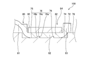
- FIG. 3 is an enlarged cross-sectional view of a fixed portion between the gear case and the boot.
- FIG. 4 is an enlarged cross-sectional view corresponding to FIG. 3 of a fixed portion between the gear case and the boot according to the modified example.
- the electric power steering device 100 as the steering device according to the embodiment of the present invention will be described with reference to the drawings.
- the electric power steering device 100 serves as a steering shaft 20 that rotates by a steering torque input from the steering wheel 10 and a steering shaft that steers the wheel 1 with the rotation of the steering shaft 20.
- a rack shaft 30 is provided.
- the steering shaft 20 is a torsion bar that connects an input shaft 21 that rotates with a steering operation in which the driver operates the steering wheel 10, an output shaft 22 that displaces the rack shaft 30, and the input shaft 21 and the output shaft 22. 23 and.
- the rack shaft 30 is a shaft-shaped member extending in the left-right direction of the vehicle, and is connected to one wheel 1 via a first tie rod 41a and a first knuckle arm 42a. Further, the rack shaft 30 is connected to the other wheel 1 via the second tie rod 41b and the second knuckle arm 42b.
- the first and second tie rods 41a and 41b are swingably connected to the rack shaft 30 via first and second ball joints 43a and 43b as connecting portions provided at both ends of the rack shaft 30.
- the connecting portion for connecting the rack shaft 30 and the first and second tie rods 41a and 41b is not limited to the first and second ball joints 43a and 43b, and other types of universal joints may be used. good.
- the output shaft 22 and the rack shaft 30 are connected to each other via a rack and pinion mechanism including a pinion gear 22a provided at the end of the output shaft 22 and a rack gear 30a provided on the rack shaft 30.
- the pinion gear 22a and the rack gear 30a are meshed with each other, and the torque of the output shaft 22 is converted into a load in the axial direction of the rack shaft 30 via the pinion gear 22a and the rack gear 30a and transmitted to the rack shaft 30.
- the rack shaft 30 is displaced in the axial direction by the transmitted torque, and the wheels 1 are steered via the first and second tie rods 41a and 41b.
- the electric power steering device 100 includes an electric motor 50 that is driven to assist the steering force in response to the steering operation, and a deceleration unit 52 that decelerates the rotation of the electric motor 50 and transmits it to the steering shaft 20. Be prepared.
- the deceleration unit 52 is a worm gear mechanism including a worm shaft 53 driven by an electric motor 50 and a worm wheel 54 provided on the output shaft 22.
- the worm shaft 53 and the worm wheel 54 mesh with each other, and the torque of the electric motor 50 is transmitted to the output shaft 22 via the worm shaft 53 and the worm wheel 54.
- the torque transmitted from the electric motor 50 to the output shaft 22 is further transmitted to the rack shaft 30 via the pinion gear 22a and the rack gear 30a.
- the electric power steering device 100 further includes a torque sensor 62 that detects the torque acting on the torsion bar 23, and a controller 60 that controls the drive of the electric motor 50 according to the detection value of the torque sensor 62.
- the controller 60 includes a CPU (Central Processing Unit) that performs arithmetic processing, a ROM (Read-Only Memory) that stores a control program and the like executed by the CPU, and a RAM (random access memory) that stores the arithmetic results of the CPU. And consists of a microcomputer including.
- the controller 60 may be composed of a single microcomputer or may be composed of a plurality of microcomputers.
- the torque sensor 62 detects the steering torque applied to the input shaft 21 as the driver operates the steering, and outputs a signal corresponding to the detected steering torque to the controller 60.
- the controller 60 calculates the torque output by the electric motor 50 based on the signal from the torque sensor 62, and controls the drive of the electric motor 50 so that the torque is generated.
- the steering torque applied to the input shaft 21 is detected by the torque sensor 62, and the drive of the electric motor 50 is controlled by the controller 60 based on the detection result. It is possible to assist the driver's steering operation.
- the electric power steering device 100 includes a gear case 70 as a housing that accommodates the rack shaft 30 and has openings 71a and 71b from which the rack shaft 30 protrudes.
- the gear case 70 is made of a metal such as aluminum.
- the electric power steering device 100 includes boots 80a and 80b that cover the openings 71a and 71b of the gear case 70, and boot bands 90a as an annular band portion that presses and fixes the boots 80a and 80b toward the outer peripheral surface 72 of the gear case 70. , 90b and.
- the boots 80a and 80b cover the rack shaft 30 protruding from the openings 71a and 71b of the gear case 70 and the first and second tie rods 41a and 41b (see FIG. 1), respectively.
- the boots 80a and 80b protect the rack shaft 30 and the first and second tie rods 41a and 41b from foreign matter.
- boot bands 90a and 90b are formed with predetermined lengths in the axial direction, and the boots 80a and 80b are fastened and fixed to the outer peripheral surface 72 of the gear case 70, respectively.
- the openings 71a and 71b are covered with the boots 80a and 80b, and foreign matter is prevented from entering the gear case 70 from the openings 71a and 71b.
- the configurations of the vicinity of the opening 71a and the vicinity of the opening 71b, the boots 80a and the boots 80b, and the boot band 90a and the boot band 90b are the same. Therefore, in the following, the configuration of the vicinity of the opening 71a, the boot 80a, and the boot band 90a on the left side in FIG. 2 will be described, and the configuration of the vicinity of the opening 71b, the boot 80b, and the boot band 90b will be omitted. Further, in the following, the opening 71a is also simply referred to as “opening 71”, the boot 80a is simply referred to as “boot 80”, and the boot band 90a is simply referred to as “boot band 90”.
- the gear case 70 has an accommodating hole 73 for accommodating the rack shaft 30, and a recess 74 formed on the outer peripheral surface 72 to which the boot band 90 is attached together with the boot 80.
- the accommodating hole 73 penetrates the gear case 70, and an opening 71 is formed at the end thereof.
- the rack shaft 30 penetrates the accommodating hole 73 and protrudes from the opening 71.
- the recess 74 is formed in an annular shape in the vicinity of the opening 71, and the axial length is formed longer than the axial length of the boot band 90. That is, on the outer peripheral surface 72 of the gear case 70, a part of the recess 74 is pressed inward in the radial direction by the boot band 90.
- the gear case 70 has a pressed portion 75 of the outer peripheral surface 72 that is pressed by the boot band 90.
- the pressed portion 75 refers to a region of the recess 74 located inside the boot band 90 in the radial direction.
- the recess 74 is formed with an annular protrusion 76 that protrudes from the pressed portion 75 in the radial direction of the opening 71.
- the protrusion 76 is formed between both ends of the pressed portion 75 in the axial direction of the opening 71.
- two protrusions 76 having the same shape are formed in the vicinity of the center of the recess 74 with an axial interval.
- the protrusion 76 extends from the bottom surface of the recess 74 of the gear case 70 toward the wall portion 76a extending perpendicular to the axial direction of the opening 71, and from the bottom surface of the recess 74 toward the wall portion 76a so as to be separated from the opening 71. It has a tapered portion 76b and a connecting portion 76c that connects the wall portion 76a and the tapered portion 76b. Specifically, the wall portion 76a projects from the pressed portion 75 of the outer peripheral surface 72 along the radial direction of the opening 71. The tapered portion 76b is formed so that the amount of radial protrusion of the opening 71 increases as it approaches the wall portion 76a.
- the connecting portion 76c is provided along the axial direction of the opening 71. That is, the protruding portion 76 is formed so that the cross section of the opening 71 along the axial direction is trapezoidal.
- the bottom surface of the recess 74 from which the wall portion 76a and the tapered portion 76b extend is a part of the outer peripheral surface 72.
- the tapered portion 76b is provided on the opening 71 side of the gear case 70 with respect to the wall portion 76a. Specifically, the opening 71a and the opening 71b will be described. In the protruding portion 76 formed in the recess 74 in the vicinity of the opening 71a, the tapered portion 76b is provided on the opening 71a side of the wall portion 76a. Further, although not shown, in the protruding portion formed in the concave portion near the opening 71b, the tapered portion is provided on the opening 71b side with respect to the wall portion.
- the boot 80 is, for example, a bellows-shaped tubular member made of rubber or resin.
- the boot 80 can be expanded and contracted in the axial direction of the rack shaft 30 so as to be able to follow the reciprocating motion of the rack shaft 30.
- the boot 80 has a main body portion 81 and an annular mounting portion 82 provided at the end of the main body portion 81 and attached to the gear case 70.
- the inner peripheral surface of the mounting portion 82 comes into contact with the bottom surface of the recess 74 of the gear case 70.
- a flange portion 83 protruding outward in the radial direction of the mounting portion 82 is formed.
- a storage space 84 in which the boot band 90 can be accommodated is formed on the outer peripheral surface of the mounting portion 82 by the boundary between the main body portion 81 and the mounting portion 82 and the flange portion 83.
- the accommodation space 84 is formed in a concave shape, and the axial length is formed longer than the axial length of the boot band 90 so that the boot band 90 can be accommodated.
- the boot 80 is attached to the gear case 70 from the opening 71 side so that the inner peripheral surface of the attachment portion 82 is accommodated in the recess 74, and then the boot band 90 is attached to the accommodation space 84. Then, it is tightened and fixed in the recess 74 of the gear case 70.
- the other end of the boot 80 is fixed to the first tie rod 41a.
- the boot 80 when the boot 80 is tightened and fixed to the gear case 70 by the boot band 90, the boot 80 is pressed toward the protruding portion 76 of the gear case 70. Therefore, the load from the boot band 90 is more likely to act on the boot 80 at the protruding portion 76 than at the other portion of the pressed portion 75. Therefore, the contact surface pressure between the gear case 70 and the boot 80 is increased at the protruding portion 76, and the protruding portion 76 of the gear case 70 and the boot 80 can be brought into close contact with each other.
- the contact surface pressure between the gear case 70 and the boot 80 increases at the corner between the wall portion 76a and the connecting portion 76c, and the gear case 70 and the boot 80 come into close contact with each other. Therefore, the sealing property between the gear case 70 and the boot 80 can be improved.
- the gear case and the boot are in contact with each other on a cylindrical surface, and the contact surface between the gear case and the boot is linear in the axial cross section of the opening. In this configuration, the entry path of foreign matter that tries to enter the gear case through between the gear case and the boot is short.
- the gear case 70 of the electric power steering device 100 in the present embodiment has the protruding portion 76, the intrusion route of foreign matter that tries to enter the gear case 70 through between the gear case 70 and the boots 80 becomes long. Therefore, the sealing property between the gear case 70 and the boot 80 can be improved.
- the sealing property between the gear case 70 and the boots 80 is high, so that the inside of the gear case 70 is contained. It is possible to suppress the progress of corrosion of the aluminum gear case 70 caused by the intrusion of muddy water or salt water.
- a tapered portion 76b extending toward the wall portion 76a is provided on the opening 71 side of the gear case 70 with respect to the wall portion 76a.
- the tapered portion 76b is provided on the opening 71a side with respect to the wall portion 76a.
- the tapered portion 76b is provided on the opening 71b side with respect to the wall portion 76a.
- the boot 80 when the boot 80 is attached to the gear case 70 from the opening 71 side, the boot 80 can easily get over the protruding portion 76 by the tapered portion 76b, so that the attachment of the boot 80 to the gear case 70 is hindered by the protruding portion 76. Not done. Further, since the attached boot 80 is locked to the wall portion 76a, the boot 80 is prevented from falling off from the gear case 70.
- the boot 80 since the boot 80 is pressed toward the protruding portion 76 of the gear case 70, the boot 80 receives a load from the boot band 90 at the protruding portion 76 more than other portions at the pressed portion 75. It becomes easier to work. Therefore, the contact surface pressure between the gear case 70 and the boot 80 is increased at the protruding portion 76, and the protruding portion 76 of the gear case 70 and the boot 80 can be brought into close contact with each other. In the present embodiment, the contact surface pressure between the gear case 70 and the boot 80 increases at the corner between the wall portion 76a and the connecting portion 76c, and the gear case 70 and the boot 80 come into close contact with each other. Therefore, the sealing property between the gear case 70 and the boot 80 can be improved.
- the gear case 70 Since the gear case 70 has a protruding portion 76, the entry path of foreign matter that tries to enter the gear case 70 through between the gear case 70 and the boot 80 becomes long. Therefore, the sealing property between the gear case 70 and the boot 80 can be improved.
- the protruding portion 76 has a tapered portion 76b extending toward the wall portion 76a provided on the opening side 55 of the gear case 70 with respect to the wall portion 76a. Therefore, when the boot 80 is attached to the gear case 70 from the opening 71 side, the boot 80 can easily get over the protruding portion 76 by the tapered portion 76b, so that the attachment of the boot 80 to the gear case 70 is hindered by the protruding portion 76. Not done. Further, since the attached boot 56 is locked to the wall portion 76a, the boot 80 is prevented from falling off from the gear case 70.
- the electric power steering device 100 is provided as a protruding portion with a protruding portion 77 as a first protruding portion and a protrusion 71 away from the center of the pressed portion 75 in the axial direction of the opening 71. It may be configured to have a protrusion 78 and a protrusion 79 as the second protrusion.
- the protruding portion 77 is provided, for example, near the center of the pressed portion 75.
- the protrusion 78 is provided on the opening 71 side of the protrusion 77, and the protrusion 79 is formed on the side opposite to the protrusion 78 with respect to the protrusion 77. That is, the protrusions 78 and 79 are provided on the end side of the pressed portion 75 with respect to the protrusion 77 in the axial direction of the opening 71.
- the protruding portion 77 has a wall portion 77a, a tapered portion 77b, and a connecting portion 77c, similarly to the protruding portion 76 in the above embodiment.
- the protrusion 78 is a wall portion 78a extending perpendicularly to the axial direction of the opening 71 from the pressed portion 75, and a tapered portion 78b extending away from the opening 71 from the pressed portion 75 toward the wall portion 78a. And, the wall portion 78a and the tapered portion 78b are continuous.
- the protruding portion 79 has a wall portion 79a and a tapered portion 79b, similarly to the protruding portion 78.
- the protrusion 78 and the protrusion 79 are formed so that the amount of protrusion of the opening 71 from the concave portion 74 in the radial direction is larger than that of the protrusion 77.
- the wall portions 78a and 79a are formed so that the radial length of the opening portion 71 is longer than that of the wall portion 77a. Therefore, in the protrusions 78 and 79 provided on the end side of the pressed portion 75 with respect to the protrusion 77, the amount of protrusion in the radial direction of the opening 71 is larger, so that the load from the boot band 90 is larger than that of the protrusion 77. Becomes easier to work with. Therefore, the contact surface pressure between the gear case 70 and the boot 80 increases on the end side of the pressed portion 75.
- the inner peripheral surface of the mounting portion 82 of the boot 80 comes into contact with the bottom surface of the recess 74 of the gear case 70. Therefore, the boot 80 is thick on the central side of the recess 74 in the axial direction, and the boot 80 is thin on both ends of the recess 74 in the axial direction. In other words, the boot 80 tends to be thin on both ends of the pressed portion 75.
- the contact surface pressure between the gear case 70 and the boot 80 is lower than in the place where the boot 80 is thick, so that the sealing property between the gear case 70 and the boot 80 may be deteriorated.
- the contact surface pressure between the gear case 70 and the boot 80 increases on the end side of the pressed portion 75 where the boot 80 tends to be thin, so that the sealing property between the gear case 70 and the boot 80 is efficient. Can be improved.
- Only one of the protrusions 78 and 79 may be formed.
- an opening between any of the protrusions and a protrusion provided from the center of the pressed portion 75 in the axial direction of the opening 71 away from the protrusion It is desirable that the amount of protrusion in the radial direction of the portion 71 is compared, and the amount of protrusion of the latter is larger. Even with these configurations, the sealing property between the gear case 70 and the boot 80 can be efficiently improved as described above.
- the number of protrusions may be one or a plurality of three or more. When the number of protrusions is plurality, they may be provided at intervals in the axial direction.
- the protruding portions have a dimension smaller than that of the pressed portion 75 in the axial direction of the opening 71.
- the dimension of the protruding portion means, for example, in the protruding portion 76, from the boundary between the pressed portion 75 and the tapered portion 76b to the boundary between the pressed portion 75 and the wall portion 76a.
- the protrusion is configured such that the length of the opening 71 in the axial direction decreases as the distance from the pressed portion 75 in the radial direction increases, the protrusion is pressed in the axial direction of the opening 71. It may have the same dimensions as the portion 75.
- a projecting portion 76 having a trapezoidal cross section along the axial direction of the opening portion 71 is provided as the projecting portion.
- the shape of the protruding portion is not limited to the above.
- the cross section of the protrusion along the axial direction of the opening 71 may be formed to be triangular, square, or semicircular.
- the protrusions having different amounts of protrusions in the radial direction of the opening 71 are mixed. You may.
- the electric power steering device 100 as a steering device includes a rack shaft 30 for steering wheels 1, a gear case 70 as a housing having an opening 71 for accommodating the rack shaft 30 and a protrusion of the rack shaft 30, and a gear case 70.
- the boot 80 covers the opening 71 of the gear case 71, and the boot band 90 as an annular band portion for pressing and fixing the boot 80 toward the outer peripheral surface 72 of the gear case 70. It has a pressed portion 75 pressed by the band 90, and an annular protruding portion 76, 77, 78, 79 protruding from the pressed portion 75 in the radial direction of the opening 71.
- the protruding portions 76, 77, 78, 79 have a dimension smaller than that of the pressed portion 75 in the axial direction of the opening 71.
- the boot 80 is pressed toward the protrusions 76, 77, 78, 79 of the gear case 70, so that the boot 80 has more protrusions 76, 77, 78 than the other parts of the pressed portion 75. , 79, the load from the boot band 90 is likely to act. Therefore, the contact surface pressure between the gear case 70 and the boot 80 increases at the protrusions 76, 77, 78, 79. As a result, the protruding portions 76, 77, 78, 79 of the gear case 70 and the boot 80 can be brought into close contact with each other.
- the protruding portions 76, 77, 78, 79 have wall portions 76a, 77a, 78a, 79a extending perpendicularly to the axial direction from the pressed portion 75, and wall portions 76a, 77a, 78a from the pressed portion 75. It has tapered portions 76b, 77b, 78b, 79b extending toward 79a, and the tapered portions 76b, 77b, 78b, 79b are closer to the opening 71 side of the gear case 70 than the wall portions 76a, 77a, 78a, 79a. It will be provided.
- the tapered portions 76b, 77b, 78b, 79b extending toward the wall portions 76a, 77a, 78a, 79a are provided on the opening 71 side of the gear case 70 with respect to the wall portions 76a, 77a, 78a, 79a.
- the attachment of the boot 80 to the gear case 70 is not hindered by the protrusions 76, 77, 78, 79. Further, since the attached boot 80 is locked to the wall portions 76a, 77a, 78a, 79a, the boot 80 is prevented from falling off from the gear case 70.
- the electric power steering device 100 has a protrusion 77 as a first protrusion and a protrusion as a second protrusion provided from the center of the pressed portion 75 in the axial direction away from the protrusion 77 as the protrusion.
- the protrusions 78 and 79 have portions 78 and 79, and the protrusion amount in the radial direction of the protrusions 78 and 79 is larger than that of the protrusion 77.
- the protrusions 78 and 79 formed on the end side of the pressed portion 75 have a larger radial protrusion than the protrusion 77 on the center side of the pressed portion 75. Since it is large, the contact surface pressure between the gear case 70 and the boot 80 increases on the end side of the pressed portion 75. Here, the wall thickness of the boot 80 tends to be thin on the end side of the pressed portion 75. Therefore, since the contact surface pressure between the gear case 70 and the boot 80 increases at the place where the boot 80 tends to be thin, the sealing property between the gear case 70 and the boot 80 can be efficiently improved.
Landscapes
- Engineering & Computer Science (AREA)
- General Engineering & Computer Science (AREA)
- Mechanical Engineering (AREA)
- Chemical & Material Sciences (AREA)
- Combustion & Propulsion (AREA)
- Transportation (AREA)
- Power Steering Mechanism (AREA)
- Sealing Devices (AREA)
- Diaphragms And Bellows (AREA)
Abstract
電動パワーステアリング装置(100)は、車輪を転舵するためのラック軸(30)と、ラック軸(30)を収容しラック軸(30)が突出する開口部(71)を有するハウジングとしてのギヤケース(70)と、ギヤケース(70)の開口部(71)を覆うブーツ(80)と、ブーツ(80)をギヤケース(70)の外周面(90)に向けて押圧し固定する環状のバンド部としてのブーツバンド(90)と、を備え、ギヤケース(70)は、外周面(90)のうちブーツバンド(90)によって押圧される被押圧部(75)と、被押圧部(75)から開口部(71)の径方向に突出する環状の突出部(76,77,78,79)と、を有する。
Description
本発明は、ステアリング装置に関する。
JP2020-171105Aに記載のステアリング装置では、ギヤケースに筒状のブーツが取り付けられる。ブーツは、ブーツバンドによりギヤケースの円筒部に締め付けられ固定される。
このようなステアリング装置では、ブーツバンドによりギヤケースの円筒部にブーツが締め付けられることで、ギヤケースとブーツとの間の隙間を通じたギヤケース内への異物の侵入が防止される。しかしながら、ブーツが締め付けられるギヤケースの円筒部の外周面が軸方向の断面において平坦であると、ギヤケースとブーツとの接触面は当該断面において直線状となるため、ギヤケースとブーツとの間で高いシール性を得られない可能性がある。
本発明は、上記の問題点に鑑みてなされたものであり、ステアリング装置のハウジングとブーツとの間のシール性を向上させることを目的とする。
本発明のある態様によれば、ステアリング装置であって、車輪を転舵するためのラック軸と、前記ラック軸を収容し前記ラック軸が突出する開口部を有するハウジングと、前記ハウジングの前記開口部を覆うブーツと、前記ブーツを前記ハウジングの外周面に向けて押圧し固定する環状のバンド部と、を備え、前記ハウジングは、前記外周面のうち前記バンド部によって押圧される被押圧部と、前記被押圧部から前記開口部の径方向に突出する環状の突出部と、を有する。
図面を参照して、本発明の実施形態に係るステアリング装置としての電動パワーステアリング装置100について説明する。
図1に示すように、電動パワーステアリング装置100は、ステアリングホイール10から入力される操舵トルクによって回転するステアリングシャフト20と、ステアリングシャフト20の回転に伴って車輪1を転舵させる転舵軸としてのラック軸30と、を備える。
ステアリングシャフト20は、運転者がステアリングホイール10を操作するステアリング操作に伴って回転する入力シャフト21と、ラック軸30を変位させる出力シャフト22と、入力シャフト21と出力シャフト22とを連結するトーションバー23と、により構成される。
ラック軸30は、車両の左右方向に延びて設けられる軸状部材であり、第一タイロッド41a及び第一ナックルアーム42aを介して一方の車輪1に連結される。また、ラック軸30は、第二タイロッド41b及び第二ナックルアーム42bを介して他方の車輪1に連結される。
第一及び第二タイロッド41a,41bは、ラック軸30の両端部に設けられる連結部としての第一及び第二ボールジョイント43a,43bを介してラック軸30に対してそれぞれ揺動自在に連結される。なお、ラック軸30と第一及び第二タイロッド41a,41bとを連結する連結部としては、第一及び第二ボールジョイント43a,43bに限定されず、他の形式の自在継手が用いられてもよい。
出力シャフト22とラック軸30とは、出力シャフト22の端部に設けられるピニオンギヤ22aと、ラック軸30に設けられるラックギヤ30aと、からなるラックアンドピニオン機構を介して互いに連結される。ピニオンギヤ22aとラックギヤ30aとは互いに噛み合っており、出力シャフト22のトルクは、ピニオンギヤ22a及びラックギヤ30aを介してラック軸30の軸心方向の荷重に変換されてラック軸30に伝達される。これにより、ラック軸30は、伝達されるトルクにより軸心方向に変位し、第一及び第二タイロッド41a,41bを介して車輪1を転舵する。
また、電動パワーステアリング装置100は、ステアリング操作に応じて操舵力を補助するために駆動される電動モータ50と、電動モータ50の回転を減速してステアリングシャフト20に伝達する減速部52と、を備える。
減速部52は、電動モータ50により駆動されるウォームシャフト53と、出力シャフト22に設けられるウォームホイール54と、からなるウォームギヤ機構である。ウォームシャフト53とウォームホイール54とは互いに噛み合っており、電動モータ50のトルクは、ウォームシャフト53及びウォームホイール54を介して出力シャフト22に伝達される。電動モータ50から出力シャフト22に伝達されたトルクは、ピニオンギヤ22a及びラックギヤ30aを介してラック軸30に更に伝達される。
また、電動パワーステアリング装置100は、トーションバー23に作用するトルクを検出するトルクセンサ62と、トルクセンサ62の検出値に応じて電動モータ50の駆動を制御するコントローラ60と、を更に備える。
コントローラ60は、演算処理を行うCPU(Central Processing Unit)と、CPUにより実行される制御プログラム等を記憶するROM(Read-Only Memory)と、CPUの演算結果等を記憶するRAM(random access memory)と、を含むマイクロコンピュータで構成される。コントローラ60は、単一のマイクロコンピュータで構成されていてもよいし、複数のマイクロコンピュータで構成されていてもよい。
トルクセンサ62は、運転者によるステアリング操作に伴って入力シャフト21に付与される操舵トルクを検出し、検出した操舵トルクに対応する信号をコントローラ60に出力する。コントローラ60は、トルクセンサ62からの信号に基づいて、電動モータ50が出力するトルクを演算し、そのトルクが発生するように電動モータ50の駆動を制御する。
このように、上記構成の電動パワーステアリング装置100では、入力シャフト21に付与される操舵トルクをトルクセンサ62にて検出し、その検出結果に基づいて電動モータ50の駆動をコントローラ60にて制御して運転者のステアリング操作をアシストすることが可能である。
図2に示すように、電動パワーステアリング装置100は、ラック軸30を収容しラック軸30が突出する開口部71a,71bを有するハウジングとしてのギヤケース70を備える。ギヤケース70は、例えば、アルミニウム等の金属で形成される。
電動パワーステアリング装置100は、ギヤケース70の開口部71a,71bを覆うブーツ80a,80bと、ブーツ80a,80bをギヤケース70の外周面72に向けて押圧し固定する環状のバンド部としてのブーツバンド90a,90bと、を備える。ブーツ80a,80bは、ギヤケース70の開口部71a,71bから突出したラック軸30と、第一及び第二タイロッド41a,41b(図1参照)と、をそれぞれ覆う。これにより、ブーツ80a,80bは、ラック軸30と第一及び第二タイロッド41a,41bを異物から保護する。また、ブーツバンド90a,90bは、軸方向に所定の長さで形成され、ブーツ80a,80bをそれぞれギヤケース70の外周面72に締め付けて固定する。これにより、開口部71a,71bがブーツ80a,80bにより覆われ、開口部71a,71bからギヤケース70内に異物が侵入することが防止される。
開口部71a近傍と開口部71b近傍、ブーツ80aとブーツ80b、及びブーツバンド90aとブーツバンド90bの構成は同様である。そのため、以下では図2における左側の開口部71a近傍、ブーツ80a、及びブーツバンド90aの構成について説明し、開口部71b近傍、ブーツ80b、及びブーツバンド90bの構成については説明を省略する。また、以下では、開口部71aを単に「開口部71」、ブーツ80aを単に「ブーツ80」、ブーツバンド90aを単に「ブーツバンド90」とも称する。
ギヤケース70は、ラック軸30を収容する収容孔73と、外周面72に形成されブーツバンド90がブーツ80とともに取り付けられる凹部74と、を有する。収容孔73は、ギヤケース70を貫通し、端部に開口部71が形成される。ラック軸30は、収容孔73を挿通して開口部71から突出する。凹部74は、開口部71近傍に環状に形成され、軸方向の長さはブーツバンド90の軸方向の長さよりも長く形成される。つまり、ギヤケース70の外周面72では、凹部74の一部がブーツバンド90によって径方向内側に向けて押圧される。言い換えれば、ギヤケース70は、外周面72のうちブーツバンド90によって押圧される被押圧部75を有する。具体的には、被押圧部75は、凹部74のうちブーツバンド90の径方向内側に位置する領域を指す。
図3に示すように、凹部74には、被押圧部75から開口部71の径方向に突出する環状の突出部76が形成される。言い換えると、突出部76は、開口部71の軸方向における被押圧部75の両端部の間に形成される。本実施形態では、同一形状の突出部76が凹部74の中央付近に軸方向に間隔を空けて二つ形成される。
突出部76は、ギヤケース70の凹部74の底面から開口部71の軸方向に対して垂直に延びる壁部76aと、凹部74の底面から壁部76aに向けて、開口部71から離れるように延びるテーパ部76bと、壁部76aとテーパ部76bとを接続する接続部76cと、を有する。具体的には、壁部76aは、外周面72の被押圧部75から開口部71の径方向に沿って突出する。テーパ部76bは、壁部76aに近づくにつれて開口部71の径方向への突出量が大きくなるように形成される。接続部76cは、開口部71の軸方向に沿って設けられる。つまり、突出部76は、開口部71の軸方向に沿った断面が台形となるように形成される。なお、壁部76a及びテーパ部76bが延びる凹部74の底面は、外周面72の一部である。
テーパ部76bは、壁部76aよりもギヤケース70の開口部71側に設けられる。具体的に開口部71a、開口部71bを用いて説明すると、開口部71a近傍の凹部74に形成される突出部76では、テーパ部76bが壁部76aよりも開口部71a側に設けられる。また、図示しないが、開口部71b近傍の凹部に形成される突出部では、テーパ部が壁部よりも開口部71b側に設けられる。
ブーツ80は例えばゴムや樹脂で形成される蛇腹状の筒部材である。ブーツ80は、ラック軸30の往復動に追従できるように、ラック軸30の軸方向に伸縮可能である。ブーツ80は、本体部81と、本体部81の端部に設けられギヤケース70に取り付けられる環状の取付部82を有する。取付部82の内周面は、ギヤケース70の凹部74の底面と当接する。本体部81と反対側の取付部82の端部には、取付部82の径方向外側に突出したフランジ部83が形成される。本体部81と取付部82の境界と、フランジ部83と、によって、ブーツバンド90が収容可能な収容空間84が取付部82の外周面に形成される。収容空間84は凹状に形成され、ブーツバンド90が収容可能なように、軸方向の長さはブーツバンド90の軸方向の長さよりも長く形成される。ブーツ80は、取付部82の内周面が凹部74に収容されるように開口部71側からギヤケース70に取り付けられたのち、ブーツバンド90が収容空間84に取り付けられる。そして、ギヤケース70の凹部74に締め付けられて固定される。ブーツ80の他端部は、第一タイロッド41aに固定される。
このように、ブーツ80がブーツバンド90によりギヤケース70に締め付けられて固定されると、ブーツ80はギヤケース70の突出部76に向けて押圧される。そのため、ブーツ80には、被押圧部75における他の部分よりも突出部76においてブーツバンド90からの荷重が作用しやすくなる。したがって、突出部76でギヤケース70とブーツ80との接触面圧が高くなり、ギヤケース70の突出部76とブーツ80とを密着させることができる。本実施形態では、壁部76aと接続部76cとの間の角部でギヤケース70とブーツ80との接触面圧が高くなり、ギヤケース70とブーツ80とが密着する。よって、ギヤケース70とブーツ80との間のシール性を向上させることができる。
また、ギヤケースが突出部を有さない場合は、ギヤケースとブーツとが円筒面で接触し、ギヤケースとブーツとの接触面が開口部の軸方向の断面において直線状となる。この構成では、ギヤケースとブーツとの間を通じてギヤケース内に侵入しようとする異物の侵入経路が短い。これに対し、本実施形態における電動パワーステアリング装置100のギヤケース70は、突出部76を有するため、ギヤケース70とブーツ80との間を通じてギヤケース70内に侵入しようとする異物の侵入経路が長くなる。よって、ギヤケース70とブーツ80との間のシール性を向上させることができる。
したがって、例えば、電動パワーステアリング装置100が泥水を受けた場合や、品質試験等で塩水を受けた場合であっても、ギヤケース70とブーツ80との間のシール性が高いため、ギヤケース70内に泥水や塩水が侵入して生じるアルミニウム製のギヤケース70の腐食の進行を抑制することができる。
また、突出部76は、壁部76aに向けて延びるテーパ部76bが壁部76aよりもギヤケース70の開口部71側に設けられる。具体的には、開口部71a近傍の凹部74に形成される突出部76では、テーパ部76bが壁部76aよりも開口部71a側に設けられる。また、開口部71b近傍の凹部74に形成される突出部76では、テーパ部76bが壁部76aよりも開口部71b側に設けられる。そのため、ブーツ80を開口部71側からギヤケース70に取り付ける際に、ブーツ80がテーパ部76bにより突出部76を容易に乗り越えることができるため、ギヤケース70へのブーツ80の取り付けが突出部76により阻害されない。また、取り付けられたブーツ80が壁部76aに係止されるため、ブーツ80がギヤケース70から脱落することが防止される。
以上の本実施形態によれば、以下に示す作用効果を奏する。
電動パワーステアリング装置100では、ブーツ80はギヤケース70の突出部76に向けて押圧されるため、ブーツ80には、被押圧部75における他の部分よりも突出部76においてブーツバンド90からの荷重が作用しやすくなる。したがって、突出部76でギヤケース70とブーツ80との接触面圧が高くなり、ギヤケース70の突出部76とブーツ80とを密着させることができる。本実施形態では、壁部76aと接続部76cとの間の角部でギヤケース70とブーツ80との接触面圧が高くなり、ギヤケース70とブーツ80とが密着する。よって、ギヤケース70とブーツ80との間のシール性を向上させることができる。
ギヤケース70は、突出部76を有するため、ギヤケース70とブーツ80との間を通じてギヤケース70内に侵入しようとする異物の侵入経路が長くなる。よって、ギヤケース70とブーツ80との間のシール性を向上させることができる。
突出部76は、壁部76aに向けて延びるテーパ部76bが壁部76aよりもギヤケース70の開口部側55に設けられる。そのため、ブーツ80を開口部71側からギヤケース70に取り付ける際に、ブーツ80がテーパ部76bにより突出部76を容易に乗り越えることができるため、ギヤケース70へのブーツ80の取り付けが突出部76により阻害されない。また、取り付けられたブーツ56が壁部76aに係止されるため、ブーツ80がギヤケース70から脱落することが防止される。
次に、本実施形態の変形例について説明する。
<変形例1>
上記実施形態では、突出部として、同一形状の突出部76が被押圧部75の中央付近に軸方向に間隔を空けて二つ設けられる。しかし、例えば、図4に示すように、突出部として、形状の異なる三つの突出部77,78,79が形成されてもよい。具体的には、電動パワーステアリング装置100は、突出部として、第一突出部としての突出部77と、開口部71の軸方向において被押圧部75の中央から突出部77よりも離れて設けられる第二突出部としての突出部78及び突出部79と、を有する構成であってもよい。突出部77は例えば被押圧部75の中央付近に設けられる。突出部78は突出部77よりも開口部71側に設けられ、突出部79は突出部77に対し突出部78と反対側に形成される。つまり、突出部78,79は、開口部71の軸方向において、突出部77よりも被押圧部75の端部側に設けられる。
上記実施形態では、突出部として、同一形状の突出部76が被押圧部75の中央付近に軸方向に間隔を空けて二つ設けられる。しかし、例えば、図4に示すように、突出部として、形状の異なる三つの突出部77,78,79が形成されてもよい。具体的には、電動パワーステアリング装置100は、突出部として、第一突出部としての突出部77と、開口部71の軸方向において被押圧部75の中央から突出部77よりも離れて設けられる第二突出部としての突出部78及び突出部79と、を有する構成であってもよい。突出部77は例えば被押圧部75の中央付近に設けられる。突出部78は突出部77よりも開口部71側に設けられ、突出部79は突出部77に対し突出部78と反対側に形成される。つまり、突出部78,79は、開口部71の軸方向において、突出部77よりも被押圧部75の端部側に設けられる。
突出部77は、上記実施形態における突出部76と同様に、壁部77aと、テーパ部77bと、接続部77cと、を有する。突出部78は、被押圧部75から開口部71の軸方向に対して垂直に延びる壁部78aと、被押圧部75から壁部78aに向けて、開口部71から離れるように延びるテーパ部78bと、を有し、壁部78aとテーパ部78bが連続する。突出部79は、突出部78と同様に、壁部79aと、テーパ部79bと、を有する。突出部78及び突出部79は、開口部71の径方向への凹部74からの突出量が、突出部77よりも大きく形成される。具体的には、壁部78a及び79aは、開口部71の径方向における長さが壁部77aよりも長く形成される。よって、突出部77よりも被押圧部75の端部側に設けられる突出部78,79では、開口部71の径方向への突出量が大きいため、突出部77よりもブーツバンド90からの荷重が作用しやすくなる。そのため、被押圧部75の端部側でギヤケース70とブーツ80との接触面圧が高くなる。
ここで、ブーツ80の取付部82の内周面は、ギヤケース70の凹部74の底面と当接する。そのため、凹部74の軸方向における中央側ではブーツ80が厚く、凹部74の軸方向における両端部側ではブーツ80が薄い。言い換えれば、被押圧部75の両端部側でブーツ80が薄くなりやすい。ブーツ80が薄い箇所では、ブーツ80が厚い箇所よりもギヤケース70とブーツ80との接触面圧が低くなるため、ギヤケース70とブーツ80との間のシール性が低下するおそれがある。しかしながら、本変形例では、ブーツ80が薄くなりやすい被押圧部75の端部側でギヤケース70とブーツ80との接触面圧が高くなるため、ギヤケース70とブーツ80との間のシール性を効率的に向上させることができる。
なお、突出部78,79は、いずれか一方のみが形成されてもよい。また、突出部が四つ以上形成される場合は、いずれかの突出部と、開口部71の軸方向において被押圧部75の中央から当該突出部よりも離れて設けられる突出部と、の開口部71の径方向への突出量を比較し、後者の突出量の方が大きいことが望ましい。これらの構成であっても、上記と同様に、ギヤケース70とブーツ80との間のシール性を効率的に向上させることができる。
<変形例2>
上記実施形態では、突出部として、同一形状の突出部76が二つ設けられる。しかし、突出部の数は、一つであっても、三つ以上の複数であってもよい。突出部の数が複数である場合は、軸方向に間隔を空けて設けられればよい。このように、突出部の数を調整することで、ギヤケース70とブーツ80とが密着する場所の数や、ギヤケース70とブーツ80との間を通じてギヤケース70内に侵入しようとする異物の侵入経路の長さを段階的に調整することができる。よって、ギヤケース70とブーツ80との間のシール性を段階的に調整することができる。
上記実施形態では、突出部として、同一形状の突出部76が二つ設けられる。しかし、突出部の数は、一つであっても、三つ以上の複数であってもよい。突出部の数が複数である場合は、軸方向に間隔を空けて設けられればよい。このように、突出部の数を調整することで、ギヤケース70とブーツ80とが密着する場所の数や、ギヤケース70とブーツ80との間を通じてギヤケース70内に侵入しようとする異物の侵入経路の長さを段階的に調整することができる。よって、ギヤケース70とブーツ80との間のシール性を段階的に調整することができる。
なお、突出部の数が一つである場合は、突出部は、開口部71の軸方向において、被押圧部75よりも小さい寸法を有することが好ましい。突出部の寸法とは、例えば突出部76では、被押圧部75とテーパ部76bとの境界から被押圧部75と壁部76aとの境界までの間を指す。これにより、突出部でギヤケース70とブーツ80との接触面圧が確実に高くなり、ギヤケース70とブーツ80との間のシール性を確実に向上させることができる。しかしながら、突出部は、突出部76のように、被押圧部75から径方向に離れるにつれて開口部71の軸方向における長さが小さくなる構成であれば、開口部71の軸方向において、被押圧部75と同じ寸法を有してもよい。
<変形例3>
上記実施形態では、突出部として、開口部71の軸方向に沿った断面が台形となる突出部76が設けられる。しかし、突出部の形状は上記に限らない。例えば、開口部71の軸方向に沿った突出部の断面が三角形状、四角形状、または半円状となるように形成されてもよい。また、突出部が複数である場合は、開口部71の軸方向に沿った断面が異なる形状の突出部が混在しても、開口部71の径方向への突出量が異なる突出部が混在してもよい。
上記実施形態では、突出部として、開口部71の軸方向に沿った断面が台形となる突出部76が設けられる。しかし、突出部の形状は上記に限らない。例えば、開口部71の軸方向に沿った突出部の断面が三角形状、四角形状、または半円状となるように形成されてもよい。また、突出部が複数である場合は、開口部71の軸方向に沿った断面が異なる形状の突出部が混在しても、開口部71の径方向への突出量が異なる突出部が混在してもよい。
以上のように構成された本発明の実施形態の構成、作用、及び効果をまとめて説明する。
ステアリング装置としての電動パワーステアリング装置100は、車輪1を転舵するためのラック軸30と、ラック軸30を収容しラック軸30が突出する開口部71を有するハウジングとしてのギヤケース70と、ギヤケース70の開口部71を覆うブーツ80と、ブーツ80をギヤケース70の外周面72に向けて押圧し固定する環状のバンド部としてのブーツバンド90と、を備え、ギヤケース70は、外周面72のうちブーツバンド90によって押圧される被押圧部75と、被押圧部75から開口部71の径方向に突出する環状の突出部76,77,78,79と、を有する。
また、突出部76,77,78,79は、開口部71の軸方向において、被押圧部75よりも小さい寸法を有する。
これらの構成では、ブーツ80はギヤケース70の突出部76,77,78,79に向けて押圧されるため、ブーツ80には、被押圧部75における他の部分よりも突出部76,77,78,79においてブーツバンド90からの荷重が作用しやすくなる。そのため、突出部76,77,78,79でギヤケース70とブーツ80との接触面圧が高くなる。これにより、ギヤケース70の突出部76,77,78,79とブーツ80とを密着させることができる。
また、突出部76,77,78,79は、被押圧部75から軸方向に対して垂直に延びる壁部76a,77a,78a,79aと、被押圧部75から壁部76a,77a,78a,79aに向けて延びるテーパ部76b,77b,78b,79bと、を有し、テーパ部76b,77b,78b,79bは、壁部76a,77a,78a,79aよりもギヤケース70の開口部71側に設けられる。
この構成では、壁部76a,77a,78a,79aに向けて延びるテーパ部76b,77b,78b,79bが壁部76a,77a,78a,79aよりもギヤケース70の開口部71側に設けられるため、ギヤケース70へのブーツ80の取り付けが突出部76,77,78,79により阻害されない。また、取り付けられたブーツ80が壁部76a,77a,78a,79aに係止されるため、ブーツ80がギヤケース70から脱落することが防止される。
また、電動パワーステアリング装置100は、突出部として、第一突出部としての突出部77と、軸方向において被押圧部75の中央から突出部77よりも離れて設けられる第二突出部としての突出部78,79と、を有し、突出部78,79は、径方向への突出量が、突出部77よりも大きい。
この構成では、被押圧部75の中央側の突出部77よりも被押圧部75の端部側に形成される突出部78,79の方が、突出部77よりも径方向への突出量が大きいため、被押圧部75の端部側でギヤケース70とブーツ80との接触面圧が高くなる。ここで、ブーツ80の肉厚は被押圧部75の端部側で薄くなりやすい。よって、ブーツ80が薄くなりやすい箇所でギヤケース70とブーツ80との接触面圧が高くなるため、ギヤケース70とブーツ80との間のシール性を効率的に向上させることができる。
以上、本発明の実施形態について説明したが、上記実施形態は本発明の適用例の一部を示したに過ぎず、本発明の技術的範囲を上記実施形態の具体的構成に限定する趣旨ではない。
本願は2021年1月6日に日本国特許庁に出願された特願2021-1064に基づく優先権を主張し、この出願の全ての内容は参照により本明細書に組み込まれる。
Claims (4)
- ステアリング装置であって、
車輪を転舵するためのラック軸と、
前記ラック軸を収容し前記ラック軸が突出する開口部を有するハウジングと、
前記ハウジングの前記開口部を覆うブーツと、
前記ブーツを前記ハウジングの外周面に向けて押圧し固定する環状のバンド部と、を備え、
前記ハウジングは、
前記外周面のうち前記バンド部によって押圧される被押圧部と、
前記被押圧部から前記開口部の径方向に突出する環状の突出部と、を有するステアリング装置。 - 請求項1に記載のステアリング装置であって、
前記突出部は、前記開口部の軸方向において、前記被押圧部よりも小さい寸法を有するステアリング装置。 - 請求項1に記載のステアリング装置であって、
前記突出部は、
前記被押圧部から前記軸方向に対して垂直に延びる壁部と、
前記被押圧部から前記壁部に向けて延びるテーパ部と、を有し、
前記テーパ部は、前記壁部よりも前記ハウジングの前記開口部側に設けられるステアリング装置。 - 請求項1に記載のステアリング装置であって、
前記突出部として、第一突出部と、前記軸方向において前記被押圧部の中央から前記第一突出部よりも離れて設けられる第二突出部と、を有し、
前記第二突出部は、前記径方向への突出量が、前記第一突出部よりも大きいステアリング装置。
Priority Applications (1)
| Application Number | Priority Date | Filing Date | Title |
|---|---|---|---|
| CN202180089328.3A CN116724184B (zh) | 2021-01-06 | 2021-11-29 | 转向装置 |
Applications Claiming Priority (2)
| Application Number | Priority Date | Filing Date | Title |
|---|---|---|---|
| JP2021001064A JP7232850B2 (ja) | 2021-01-06 | 2021-01-06 | ステアリング装置 |
| JP2021-001064 | 2021-01-06 |
Publications (1)
| Publication Number | Publication Date |
|---|---|
| WO2022149369A1 true WO2022149369A1 (ja) | 2022-07-14 |
Family
ID=82357663
Family Applications (1)
| Application Number | Title | Priority Date | Filing Date |
|---|---|---|---|
| PCT/JP2021/043692 Ceased WO2022149369A1 (ja) | 2021-01-06 | 2021-11-29 | ステアリング装置 |
Country Status (3)
| Country | Link |
|---|---|
| JP (1) | JP7232850B2 (ja) |
| CN (1) | CN116724184B (ja) |
| WO (1) | WO2022149369A1 (ja) |
Citations (4)
| Publication number | Priority date | Publication date | Assignee | Title |
|---|---|---|---|---|
| US20020189890A1 (en) * | 2001-06-13 | 2002-12-19 | Trw Inc. | Boot for a rack and pinion steering gear assembly |
| JP2007146959A (ja) * | 2005-11-28 | 2007-06-14 | Ntn Corp | シール構造 |
| JP2015016717A (ja) * | 2013-07-09 | 2015-01-29 | 株式会社ジェイテクト | ステアリング装置 |
| JP2019078309A (ja) * | 2017-10-23 | 2019-05-23 | 株式会社ジェイテクト | ブーツの取付構造 |
Family Cites Families (5)
| Publication number | Priority date | Publication date | Assignee | Title |
|---|---|---|---|---|
| JPS55175662U (ja) * | 1979-06-03 | 1980-12-16 | ||
| JP3964944B2 (ja) * | 1995-12-27 | 2007-08-22 | Ntn株式会社 | ブーツ取付構造 |
| JP2004211850A (ja) * | 2003-01-07 | 2004-07-29 | Toyo Tire & Rubber Co Ltd | 樹脂ブーツ用ブッシュ |
| DE102013103977A1 (de) * | 2013-04-19 | 2014-11-06 | Contitech Vibration Control Gmbh | Dichtungsmanschette für eine Drehgelenkkupplung |
| CN209370278U (zh) * | 2018-12-24 | 2019-09-10 | 江苏天洋集团有限公司 | 一种用于汽车的多连杆独立悬挂机构 |
-
2021
- 2021-01-06 JP JP2021001064A patent/JP7232850B2/ja active Active
- 2021-11-29 WO PCT/JP2021/043692 patent/WO2022149369A1/ja not_active Ceased
- 2021-11-29 CN CN202180089328.3A patent/CN116724184B/zh active Active
Patent Citations (4)
| Publication number | Priority date | Publication date | Assignee | Title |
|---|---|---|---|---|
| US20020189890A1 (en) * | 2001-06-13 | 2002-12-19 | Trw Inc. | Boot for a rack and pinion steering gear assembly |
| JP2007146959A (ja) * | 2005-11-28 | 2007-06-14 | Ntn Corp | シール構造 |
| JP2015016717A (ja) * | 2013-07-09 | 2015-01-29 | 株式会社ジェイテクト | ステアリング装置 |
| JP2019078309A (ja) * | 2017-10-23 | 2019-05-23 | 株式会社ジェイテクト | ブーツの取付構造 |
Also Published As
| Publication number | Publication date |
|---|---|
| JP7232850B2 (ja) | 2023-03-03 |
| CN116724184A (zh) | 2023-09-08 |
| CN116724184B (zh) | 2026-03-27 |
| JP2022106212A (ja) | 2022-07-19 |
Similar Documents
| Publication | Publication Date | Title |
|---|---|---|
| EP3248855B1 (en) | Electric power steering system | |
| US11618495B2 (en) | Steering device | |
| US10252669B2 (en) | Warning device generating warning vibration wave for vehicle with torque detector | |
| JP6290375B2 (ja) | パワーステアリング装置 | |
| JP5773188B2 (ja) | 操舵装置 | |
| JP2017177996A (ja) | 動力伝達機構及び操舵装置 | |
| JP2020011623A (ja) | ステアリング装置 | |
| US12240530B2 (en) | Steering device | |
| CN114633795B (zh) | 助力组件 | |
| WO2022149369A1 (ja) | ステアリング装置 | |
| US12270694B2 (en) | Sensor assembly and apparatus | |
| JP2017214048A (ja) | 電動パワーステアリング装置 | |
| JP2012224274A (ja) | 操舵装置 | |
| JP7148378B2 (ja) | 車両搭載機器のハウジング構造 | |
| JP2020090262A (ja) | 電動パワーステアリング装置 | |
| JP2009067117A (ja) | ステアリング装置 | |
| JP2000190857A (ja) | 電動式パワ―ステアリング装置 | |
| JP2020179789A (ja) | 転舵ユニット | |
| JP3764770B2 (ja) | ベローズの固定構造 | |
| JP2022120920A (ja) | ステアリング装置 | |
| WO2020179324A1 (ja) | 電動パワーステアリング装置 | |
| WO2025197787A1 (en) | Steer-by-wire unit | |
| JP2020117191A (ja) | ステアリング装置 | |
| KR100646442B1 (ko) | 자동차의 전기식 동력 보조 조향 장치 | |
| JP2025019818A (ja) | シール部材 |
Legal Events
| Date | Code | Title | Description |
|---|---|---|---|
| 121 | Ep: the epo has been informed by wipo that ep was designated in this application |
Ref document number: 21917591 Country of ref document: EP Kind code of ref document: A1 |
|
| DPE1 | Request for preliminary examination filed after expiration of 19th month from priority date (pct application filed from 20040101) | ||
| WWE | Wipo information: entry into national phase |
Ref document number: 202180089328.3 Country of ref document: CN |
|
| NENP | Non-entry into the national phase |
Ref country code: DE |
|
| 122 | Ep: pct application non-entry in european phase |
Ref document number: 21917591 Country of ref document: EP Kind code of ref document: A1 |