WO2022145474A1 - 水供給装置 - Google Patents
水供給装置 Download PDFInfo
- Publication number
- WO2022145474A1 WO2022145474A1 PCT/JP2021/048973 JP2021048973W WO2022145474A1 WO 2022145474 A1 WO2022145474 A1 WO 2022145474A1 JP 2021048973 W JP2021048973 W JP 2021048973W WO 2022145474 A1 WO2022145474 A1 WO 2022145474A1
- Authority
- WO
- WIPO (PCT)
- Prior art keywords
- water supply
- additive liquid
- gear
- water
- pump
- Prior art date
- Legal status (The legal status is an assumption and is not a legal conclusion. Google has not performed a legal analysis and makes no representation as to the accuracy of the status listed.)
- Ceased
Links
Images

Classifications
-
- C—CHEMISTRY; METALLURGY
- C02—TREATMENT OF WATER, WASTE WATER, SEWAGE, OR SLUDGE
- C02F—TREATMENT OF WATER, WASTE WATER, SEWAGE, OR SLUDGE
- C02F1/00—Treatment of water, waste water, or sewage
- C02F1/68—Treatment of water, waste water, or sewage by addition of specified substances, e.g. trace elements, for ameliorating potable water
-
- F—MECHANICAL ENGINEERING; LIGHTING; HEATING; WEAPONS; BLASTING
- F04—POSITIVE - DISPLACEMENT MACHINES FOR LIQUIDS; PUMPS FOR LIQUIDS OR ELASTIC FLUIDS
- F04B—POSITIVE-DISPLACEMENT MACHINES FOR LIQUIDS; PUMPS
- F04B23/00—Pumping installations or systems
- F04B23/04—Combinations of two or more pumps
- F04B23/08—Combinations of two or more pumps the pumps being of different types
- F04B23/12—Combinations of two or more pumps the pumps being of different types at least one pump being of the rotary-piston positive-displacement type
-
- F—MECHANICAL ENGINEERING; LIGHTING; HEATING; WEAPONS; BLASTING
- F04—POSITIVE - DISPLACEMENT MACHINES FOR LIQUIDS; PUMPS FOR LIQUIDS OR ELASTIC FLUIDS
- F04B—POSITIVE-DISPLACEMENT MACHINES FOR LIQUIDS; PUMPS
- F04B23/00—Pumping installations or systems
- F04B23/04—Combinations of two or more pumps
- F04B23/08—Combinations of two or more pumps the pumps being of different types
- F04B23/14—Combinations of two or more pumps the pumps being of different types at least one pump being of the non-positive-displacement type
-
- F—MECHANICAL ENGINEERING; LIGHTING; HEATING; WEAPONS; BLASTING
- F04—POSITIVE - DISPLACEMENT MACHINES FOR LIQUIDS; PUMPS FOR LIQUIDS OR ELASTIC FLUIDS
- F04B—POSITIVE-DISPLACEMENT MACHINES FOR LIQUIDS; PUMPS
- F04B43/00—Machines, pumps, or pumping installations having flexible working members
- F04B43/12—Machines, pumps, or pumping installations having flexible working members having peristaltic action
-
- F—MECHANICAL ENGINEERING; LIGHTING; HEATING; WEAPONS; BLASTING
- F04—POSITIVE - DISPLACEMENT MACHINES FOR LIQUIDS; PUMPS FOR LIQUIDS OR ELASTIC FLUIDS
- F04C—ROTARY-PISTON, OR OSCILLATING-PISTON, POSITIVE-DISPLACEMENT MACHINES FOR LIQUIDS; ROTARY-PISTON, OR OSCILLATING-PISTON, POSITIVE-DISPLACEMENT PUMPS
- F04C2/00—Rotary-piston machines or pumps
- F04C2/08—Rotary-piston machines or pumps of intermeshing-engagement type, i.e. with engagement of co-operating members similar to that of toothed gearing
- F04C2/12—Rotary-piston machines or pumps of intermeshing-engagement type, i.e. with engagement of co-operating members similar to that of toothed gearing of other than internal-axis type
- F04C2/14—Rotary-piston machines or pumps of intermeshing-engagement type, i.e. with engagement of co-operating members similar to that of toothed gearing of other than internal-axis type with toothed rotary pistons
- F04C2/18—Rotary-piston machines or pumps of intermeshing-engagement type, i.e. with engagement of co-operating members similar to that of toothed gearing of other than internal-axis type with toothed rotary pistons with similar tooth forms
Definitions
- the present invention relates to a water supply device that adds an additive liquid such as a mineral concentrate to raw water such as tap water.
- Patent Document 1 describes a water supply device that not only has a water purification function but also distributes additives such as mineral components to water.
- the present invention has a technical problem of solving such a problem of the prior art, and an object of the present invention is to provide a water supply device capable of adding water to water by adjusting the addition concentration with high accuracy.
- the additive liquid holding portion for holding the additive liquid and the raw water to which the additive liquid should be added are distributed.
- the pump unit provided in the liquid supply pipeline is provided, the fluid motor unit is driven by the original water flowing through the water supply pipeline, and the pump unit is driven by the fluid motor unit.
- a water supply device characterized in that the additive liquid is supplied at a flow rate proportional to the flow rate of the original water flowing through the water supply line.
- the fluid motor unit is driven by the original water flowing through the water supply pipeline, and the pump unit is driven by the fluid motor unit. Therefore, the flow rate of the raw water to which the additive liquid should be supplied is driven. It is possible to supply the additive liquid accurately in proportion to the flow rate of the raw water without arranging a measuring device such as a special flow meter for measuring.
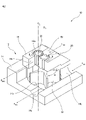
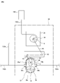
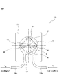
- FIG. 1 It is a schematic perspective view of the water supply device according to a preferable embodiment of the present invention. It is a perspective view which shows by breaking a part of the housing of a pump. It is a flow chart of the water supply apparatus by the 2nd Embodiment of this invention. It is a schematic sectional drawing of a tube pump.
- the water supply device 100 includes a water supply line 102 for circulating tap water as raw water, a pump 10 arranged in the water supply line 102, and a pump 10 via an additive liquid supply line 106. It is provided with a mineral source 104 as an additive liquid holding portion connected to the water supply.
- the mineral source 104 can be a pouch-shaped container as a holding portion for holding a concentrated liquid (mineral liquid) containing a mineral component such as potassium chloride or potassium chloride.
- the pump 10 includes a fluid motor unit and a pump unit driven by the fluid motor unit, and the fluid motor unit and the pump unit are housed in a common housing 12. ..
- the housing 12 defines the vehicle interior housing portion 14 and the gear housing portion 16.
- the fluid motor unit is formed of a rotary flow meter having a rotation axis extending perpendicular to the direction of flow, particularly an impeller type flow meter, and has an impeller 18 arranged in the vehicle interior housing unit 14. I have.
- the pump portion is formed by a gear pump and includes a pair of gears 20 and 22 arranged in the gear housing portion 16 and meshing with each other.
- the vehicle interior housing portion 14 forms a vehicle interior 14a accommodating the impeller 18 and an inlet port 14b and an exit port 14c communicating with the vehicle interior 14a.
- the impeller 18 is rotatably arranged around the axis O1 .
- the gear housing portion 16 forms a gear chamber 16a accommodating a pair of first and second gears 20 and 22, and an inlet port 16b and an outlet port 16c communicating with the gear chamber 16a.
- the first and second gears 20 and 22 are rotatably arranged in the gear chamber 16a about the axes O 1 and O 2 extending in parallel with each other.
- the first gear 20 is a drive gear that rotates about an axis O 1 common to the axis O 1 that is the center of rotation of the impeller 18 and is rotationally driven by the impeller 18.
- the second gear 22 that meshes with the first gear 20 is a driven gear that is rotationally driven by the first gear 20.
- the housing 12 has a shaft hole (not shown) extending along the axis O 1 between the vehicle chamber 14a and the gear chamber 16a, and the impeller 18 and the first gear 20 pass through the shaft hole.
- a common axis of rotation (not shown) is extended.
- a seal member (not shown) is provided between the inner surface of the shaft hole and the outer surface of the common rotating shaft so that the vehicle chamber 14a and the gear chamber 16a do not communicate with each other through the shaft hole.
- the inlet port 14b of the vehicle interior housing portion 14 is connected to the upstream side pipeline 102a of the water supply pipeline 102, and the outlet port 14c is connected to the downstream side pipeline 102b of the water supply pipeline 102.
- the inlet port 16b of the gear housing portion 16 is connected to the upstream side pipeline 106a of the additive liquid supply pipe 106, and the outlet port 16c is connected to the downstream side pipe 106b of the additive liquid supply pipe 106.
- the upstream side pipe 106a of the additive liquid supply pipe 106 is connected to the mineral source 104, and the downstream side pipe 106b is connected to the downstream side pipe 102b of the water supply pipe 102.
- the first gear 20 coaxially coupled to the impeller 18 also rotates about the axis O 1 as shown by the arrow B1.
- the second gear 22 that meshes with the first gear 20 rotates about the axis O 2 as shown by the arrow B2.
- the mineral liquid proportional to the flow rate of the raw water is the downstream side line 102b of the water supply line 102. Is supplied to.
- the tooth shapes, dimensions, and number of teeth of the first and second gears 20 and 22 can be appropriately determined in consideration of the amount and ratio of the mineral liquid to be added to the raw water.
- the water supply device 200 according to the second embodiment is configured in substantially the same manner as the water supply device 100 except that the pump 30 is provided in place of the pump 10 in the water supply device 100 according to the first embodiment.
- the same components as those in FIG. 1 are designated by the same reference numerals.
- the pump 30 includes a fluid motor unit 32 and a pump unit 50 driven by the fluid motor unit.
- the fluid motor unit 32 is formed of a rotary flow meter having a rotation axis extending perpendicular to the direction of flow, particularly a positive displacement flow meter having a pair of rotors, preferably a gear flow meter.
- the fluid motor unit 32 is formed of an oval gear flow meter in which a pair of rotors are oval gears, but may be a gear flow meter having circular gears as a pair of rotors. ..
- the fluid motor unit 32 may be a roots type flow meter in which a pair of rotors have a cocoon shape, instead of a gear flow meter.
- the fluid motor unit 32 forms a rotor chamber 34a accommodating a pair of oval gears 36 and 38 that mesh with each other, an inlet port 34b communicating with the rotor chamber 34a, and an outlet port 34c communicating with the rotor chamber 34a.
- a housing 34 to be formed is formed.
- the upstream side pipeline 102a of the water supply pipeline 102 is connected to the inlet port 34b, and the downstream side pipeline 102b of the water supply pipeline 102 is connected to the outlet port 34c.
- the pair of oval gears 36, 38 are rotatably supported by the housing 34 and attached to rotating shafts 36a, 38a extending in parallel.
- the pump portion 50 includes a housing 52 formed by a tube pump and defining a pump chamber 54, and a rotor assembly disposed in the pump chamber 54.
- the pump chamber 54 has an inner peripheral surface extending along the circumference with respect to the center O.
- the additive liquid supply pipe 106 is partially arranged in the pump chamber 54.
- the additive liquid supply pipe 106 has flexibility at least in a portion arranged in the pump chamber 54.
- the additive liquid supply pipe line 106 extends along the inner peripheral surface of the pump chamber 54.
- the upstream side of the portion arranged in the pump chamber 54 is the upstream side pipe 106a, and the downstream side is the downstream side pipe 106b.
- the rotor assembly is rotatably arranged in the pump chamber 54 around the center O.
- the rotor assembly has a carrier 56 that is rotatable around the center O.
- the carrier 56 has a drive shaft 58 extending along an axis that passes through the center O perpendicularly to the paper surface of FIG.
- the carrier 56 has a plurality of arms arranged at equal intervals with respect to the center O, in the example of FIG. 4, and a rotor 60 is attached to the tip of each arm.
- Each rotor 60 is rotatably attached to the tip of each arm about a rotation shaft 62 extending parallel to the drive shaft 58.
- the portion arranged in the pump chamber 54 is partially deformed by being pressed against the inner peripheral surface of the pump chamber 54 by each rotor 60.
- the deformed portion of the additive liquid supply pipe 106 moves along the inner peripheral surface of the pump chamber 54 with the rotation of the carrier 56, and the mineral liquid stored between the two adjacent deformed portions is a downstream pipe. It is pushed out to the road 106b.
- the shape (number of arms) and dimensions of the carrier 56 and the dimensions of the rotor 60 can be appropriately determined in consideration of the flow rate of the mineral liquid to be added.
- the pump unit 50 is also connected to the fluid motor unit 32 via the transmission 40. More specifically, the input shaft 42 of the transmission 40 is connected to one of the rotating shafts 36a and 38a of the pair of oval gears 36 and 38 of the fluid motor unit 32 and the rotating shaft 38a in FIG. 3, and the output of the transmission 40 is output.
- the shaft 44 is connected to the drive shaft 58 of the pump unit 50.
- the portion pressed and deformed by the rotor 60 also moves around the center O along the inner peripheral surface of the pump chamber 54 in the direction of arrow B.
- the additive liquid is supplied from the mineral source 104 to the water supply pipe 102 through the additive liquid supply pipe 106.
- the water supply device of the present invention can be incorporated into any drinking water supply system for providing drinking water, such as a water server and a water purifier. Even in such a case, since the water supply device of the present invention has a simple structure, the installation area of the entire device can be made compact.
- Pump 12 Housing 14 Car room housing part 14a Car room 14b Inlet port 14c Exit port 16 Gear housing part 16a Gear room 16b Inlet port 16c Outlet port 18 Impeller 20 First gear 22 Second gear 100 Water supply device 102 Water Supply line 102a Upstream line 102b Downstream line 104 Mineral source 106 Additive liquid supply line 106a Upstream line 106b Downstream line 30 Pump 32 Fluid motor section 34 Housing 34a Rotator chamber 34b Inlet port 34c Outlet port 36 Oval gear 36a Rotating shaft 38 Oval gear 38a Rotating shaft 40 Transmission 42 Input shaft 44 Output shaft 50 Pump part 52 Housing 54 Pump room 56 Carrier 58 Drive shaft 60 Rotor 62 Rotating shaft
Landscapes
- Engineering & Computer Science (AREA)
- General Engineering & Computer Science (AREA)
- Mechanical Engineering (AREA)
- Chemical & Material Sciences (AREA)
- Life Sciences & Earth Sciences (AREA)
- Hydrology & Water Resources (AREA)
- Environmental & Geological Engineering (AREA)
- Water Supply & Treatment (AREA)
- Organic Chemistry (AREA)
- Health & Medical Sciences (AREA)
- Medicinal Chemistry (AREA)
- Rotary Pumps (AREA)
- Details Of Reciprocating Pumps (AREA)
- Reciprocating Pumps (AREA)
- Structures Of Non-Positive Displacement Pumps (AREA)
Abstract
元水に添加液を供給する水供給装置(100)が、添加液を保持する添加液保持部(104)と、添加液を添加すべき原水が流通する水供給管路(102)と、添加液保持部と水供給管路との間に配設された添加液供給管路(106)と、水供給管路に配設された流体モータ部(18、32)と、添加液供給管路に配設されたポンプ部(20、22;50)とを具備し、水供給管路を流通する元水により流体モータ部が駆動され、該流体モータ部によりポンプ部を駆動することによって、水供給管路を流通する元水の流量に比例する流量で添加液が供給される。
Description
本発明は、水道水のような原水にミネラル濃縮液のような添加液を添加する水供給装置に関する。
現代の多様化社会においては、食品や飲料などの消費材料へのニ-ズも多様化し、健康志向や美味指向を背景に、飲用とする水に関する消費者の関心が近年高まっている。そうした流れを受け、例えば、特許文献1には、浄水機能を持たせるだけでなく、水にミネラル成分等の添加物を分与するようにした水供給装置が記載されている。
水に添加物を加える試みは従来より行われてきたものの、飲みやすい水を実現するためのミネラルバランスはデリケートであり、安定して実現するためには添加の精度を向上する必要がある。特に水道直結等の浄水器に添加機構を採用する場合、使用者が流量を任意に操作できる機構も採用できるが、その場合、全体の水流量が一定とならならいためや、添加液を供給するポンプの吐出量が一定しないために、添加濃度を高い精度で調節することが難しい問題がある。
本発明は、こうした従来技術の問題を解決することを技術課題としており、添加濃度を高い精度で調節して水に添加できるようにした水供給装置を提供することを目的としている。
上述の目的を達成するために、本発明によれば、元水に添加液を供給する水供給装置において、前記添加液を保持する添加液保持部と、前記添加液を添加すべき原水が流通する水供給管路と、前記添加液保持部と前記水供給管路との間に配設された添加液供給管路と、前記水供給管路に配設された流体モータ部と、前記添加液供給管路に配設されたポンプ部とを具備し、前記水供給管路を流通する元水により前記流体モータ部を駆動し、該流体モータ部により前記ポンプ部を駆動することによって、前記水供給管路を流通する元水の流量に比例する流量で前記添加液を供給することを特徴とする水供給装置が提供される。
本発明によれば、前記水供給管路を流通する元水により前記流体モータ部を駆動し、該流体モータ部により前記ポンプ部を駆動するようにしたので、添加液を供給すべき原水の流量を測定する特段の流量計等の計測機器を配設することなく、原水の流量に比例して添加液を正確に供給することが可能となる。
以下、添付図面を参照して、本発明の好ましい実施形態を説明する。
図1において、水供給装置100は、原水としての水道水を流通させる水供給管路102と、水供給管路102に配設されたポンプ10と、添加液供給管路106を介してポンプ10に接続された添加液保持部としてのミネラル源104を備えている。ミネラル源104は、添加液の一例として塩化カリウムや塩化カリウムのようなミネラル成分を含んだ濃縮液(ミネラル液)を保持する保持部として例えばパウチ状の容器とすることができる。
図1において、水供給装置100は、原水としての水道水を流通させる水供給管路102と、水供給管路102に配設されたポンプ10と、添加液供給管路106を介してポンプ10に接続された添加液保持部としてのミネラル源104を備えている。ミネラル源104は、添加液の一例として塩化カリウムや塩化カリウムのようなミネラル成分を含んだ濃縮液(ミネラル液)を保持する保持部として例えばパウチ状の容器とすることができる。
図2を参照すると、ポンプ10は、流体モータ部と、該流体モータ部により駆動されるポンプ部とを具備しており、流体モータ部とポンプ部とは共通するハウジング12内に収容されている。ハウジング12は、車室ハウジング部14とギアハウジング部16とを画成する。流体モータ部は、流れの方向に対してに垂直に延びる回転軸を有した回転型流量計、特に羽根車式流量計から形成され、車室ハウジング部14内に配設された羽根車18を備えている。ポンプ部は、ギアポンプにより形成され、ギアハウジング部16内に配設され互いに噛合する一対の歯車20、22を備えている。
車室ハウジング部14は、羽根車18を収容する車室14aと、車室14aに連通する入口ポート14bおよび出口ポート14cとを形成する。車室14a内において、羽根車18は、軸線O1を中心として回転可能に配設されている。
ギアハウジング部16は、対をなす第1と第2の歯車20、22を収容するギア室16aと、ギア室16aに連通する入口ポート16bおよび出口ポート16cとを形成する。第1と第2の歯車20、22は、ギア室16a内において、互いに平行に延びる軸線O1、O2を中心として回転可能に配設されている。特に、第1の歯車20は、羽根車18の回転中心となる軸線O1と共通の軸線O1を中心として回転し、羽根車18により回転駆動される駆動歯車となっている。第1の歯車20に噛合する第2の歯車22は、第1の歯車20により回転駆動される従動歯車となっている。
ハウジング12は、車室14aとギア室16aとの間に軸線O1に沿って延びる軸穴(図示せず)を有しており、該軸穴を通して羽根車18と第1の歯車20との共通の回転軸(図示せず)が延設されている。なお、該軸穴を通して車室14aとギア室16aの間が連通しないように、軸穴内面と共通の回転軸の外面との間にはシール部材(図示せず)が配設されている。
車室ハウジング部14の入口ポート14bは、水供給管路102の上流側管路102aに接続され、出口ポート14cは水供給管路102の下流側管路102bに接続される。ギアハウジング部16の入口ポート16bは、添加液供給管路106の上流側管路106aに接続され、出口ポート16cは添加液供給管路106の下流側管路106bに接続される。添加液供給管路106の上流側管路106aはミネラル源104に接続され、下流側管路106bは水供給管路102の下流側管路102bに接続される。
水供給管路102の上流側管路102aからの原水、例えば水道水が、車室ハウジング部14の入口ポート14bから車室14a内に流入すると、羽根車18を矢印Aで示すように軸線O1を中心として回転させ、出口ポート14cから水供給管路102の下流側管路102bへ流出する。
羽根車18が矢印Aの方向に回転することによって、これと同軸に結合されている第1の歯車20も軸線O1を中心として矢印B1で示すように回転しする。更に、第1の歯車20と噛合する第2の歯車22は、軸線O2を中心として矢印B2で示すように回転する。このように、第1と第2の歯車20、22が回転することによって、添加液供給管路106の上流側管路106aを介してミネラル源104からミネラル液が吸引され、下流側管路106bへ吐出される。
羽根車18および第1の歯車20の回転数は、水供給管路102を流通する原水の流量に比例するので、原水の流量に比例したミネラル液が水供給管路102の下流側管路102bに供給される。なお、第1と第2の歯車20、22の歯の形状、寸法、歯数は、原水に添加すべきミネラル液の量、割合等を勘案して適宜決定することができる。
次に、図3を参照して、本発明の第2の実施形態を説明する。
第2の実施形態による水供給装置200は、第1の実施形態による水供給装置100におけるポンプ10に代えてポンプ30を備えている点を除いて、水供給装置100と概ね同様に構成されており、図3において、図1と同様の構成要素には同じ参照符号が付されている。
第2の実施形態による水供給装置200は、第1の実施形態による水供給装置100におけるポンプ10に代えてポンプ30を備えている点を除いて、水供給装置100と概ね同様に構成されており、図3において、図1と同様の構成要素には同じ参照符号が付されている。
ポンプ30は、流体モータ部32と、該流体モータ部により駆動されるポンプ部50とを具備している。流体モータ部32は、流れの方向に対して垂直に延びる回転軸を有した回転型流量計、特に一対の回転子を有した容積型流量計、好ましくは歯車流量計から形成される。本実施形態では、流体モータ部32は、一対の回転子がオーバル歯車であるオーバル歯車流量計から形成されているが、一対の回転子として円形の歯車を有した歯車流量計であってもよい。また、流体モータ部32は、歯車流量計ではなく、一対の回転子が繭形を呈したルーツ式の流量計であってもよい。
流体モータ部32は、互いに噛合する一対のオーバル歯車36、38を収容する回転子室34aと、回転子室34aに連通する入口ポート34bと、回転子室34aに連通する出口ポート34cとを形成するハウジング34とを形成する。入口ポート34bに水供給管路102の上流側管路102aが接続され、出口ポート34cに水供給管路102の下流側管路102bが接続される。回転子室34a内において、一対のオーバル歯車36、38は、ハウジング34に回転可能に支持され平行に延設された回転軸36a、38aに取り付けられている。
図4を参照すると、ポンプ部50は、チューブポンプにより形成され、ポンプ室54を画成するハウジング52と、ポンプ室54内に配設されたロータ組立体とを備えている。ポンプ室54は、中心Oに関する円周に沿って延びる内周面を有している。添加液供給管路106は、部分的にポンプ室54内に配置される。添加液供給管路106は、少なくともポンプ室54内に配置される部分が柔軟性を有している。ポンプ室54内において、添加液供給管路106は、ポンプ室54の内周面に添わせて延設される。図4の例では、添加液供給管路106は、ポンプ室54内に配置されている部分の上流側が上流側管路106aであり、下流側が下流側管路106bとなる。
ロータ組立体は、中心O周りに回転可能にポンプ室54内に配設される。ロータ組立体は、中心O周りに回転可能なキャリア56を有している。キャリア56は、図4の紙面に垂直に中心Oを通過する軸線に沿って延びる駆動軸58を有している。キャリア56は、中心Oに関して等角度間隔に配置された複数の、図4の例では4つの腕を有しており、各腕の先端部にロータ60が、取り付けられている。各ロータ60は、駆動軸58に平行に延びる回転軸62を中心として回転可能に各腕の先端部に取り付けられている。
添加液供給管路106において、ポンプ室54内に配置されている部分は、各ロータ60によって、ポンプ室54の内周面に押圧され部分的に変形する。この添加液供給管路106の変形部分が、キャリア56の回転とともに、ポンプ室54の内周面にそって移動し、隣り合う2つの変形部分に間に貯留されているミネラル液が下流側管路106bへ押し出される。キャリア56の形状(腕の数)や寸法、および、ロータ60の寸法は、添加すべきミネラル液の流量を勘案して適宜決定することができる。
ポンプ部50は、また、変速機40を介して、流体モータ部32に連結されている。より詳細には、変速機40の入力軸42が、流体モータ部32の一対のオーバル歯車36、38の回転軸36a、38aの一方、図3では回転軸38aに連結され、変速機40の出力軸44が、ポンプ部50の駆動軸58に連結されている。
水供給管路102の上流側管路102aからの原水、例えば水道水が、流体モータ部32の入口ポート34bから回転子室34a内に流入すると、矢印B、Cで示すように一対のオーバル歯車36、38を回転させ、出口ポート14cから水供給管路102の下流側管路102bへ流出する。オーバル歯車38の回転軸38aの回転は、変速機40を介して、ポンプ部50の駆動軸58に伝達され、矢印Bで示すように、キャリア56が回転する。
これにより、添加液供給管路106において、ロータ60によって押圧され変形した部分もまた、中心O周りにポンプ室54の内周面に沿って矢印Bの方向に移動する。これにより、添加液が、ミネラル源104から水供給管路102へ添加液供給管路106を流通して供給される。
本発明の水供給装置は、ウォーターサーバー、浄水器等の、飲用水を提供するための任意の飲用水提供システムに組み込むことが可能である。そのような場合でも、本発明の水供給装置は簡易な構造であるため、装置全体の設置面積をコンパクトにすることが可能となる。
10 ポンプ
12 ハウジング
14 車室ハウジング部
14a 車室
14b 入口ポート
14c 出口ポート
16 ギアハウジング部
16a ギア室
16b 入口ポート
16c 出口ポート
18 羽根車
20 第1の歯車
22 第2の歯車
100 水供給装置
102 水供給管路
102a 上流側管路
102b 下流側管路
104 ミネラル源
106 添加液供給管路
106a 上流側管路
106b 下流側管路
30 ポンプ
32 流体モータ部
34 ハウジング
34a 回転子室
34b 入口ポート
34c 出口ポート
36 オーバル歯車
36a 回転軸
38 オーバル歯車
38a 回転軸
40 変速機
42 入力軸
44 出力軸
50 ポンプ部
52 ハウジング
54 ポンプ室
56 キャリア
58 駆動軸
60 ロータ
62 回転軸
Claims (4)
- 元水に添加液を供給する水供給装置において、
前記添加液を保持する添加液保持部と、
前記添加液を添加すべき原水が流通する水供給管路と、
前記添加液保持部と前記水供給管路との間に配設された添加液供給管路と、
前記水供給管路に配設された流体モータ部と、
前記添加液供給管路に配設されたポンプ部とを具備し、
前記水供給管路を流通する元水により前記流体モータ部を駆動し、該流体モータ部により前記ポンプ部を駆動することによって、前記水供給管路を流通する元水の流量に比例する流量で前記添加液を供給することを特徴とする水供給装置。 - 前記流体モータ部は、羽根車と、前記羽根車を回転可能に収容する車室とを具備し、
前記ポンプ部は、互いに噛合する第1と第2の歯車と、前記第1と第2の歯車を収容するギア室とを具備し、
前記第1の歯車が前記羽根車に同軸に一体的に回転するように結合されており、
前記車室内に流入する原水によって前記羽根車が回転し、これと同軸に回転する第1の歯車および該第1の歯車に噛合する第2の歯車が回転して、前記添加液保持部から添加液が、前記ギア室を通過して吐出され、前記車室から流出する原水に添加されることを特徴とする請求項1に記載の水供給装置。 - 前記流体モータ部は、一対の回転子と、該一対の回転子を回転可能に収容する回転子室とを具備し、
前記ポンプ部は、円周に沿って延びる内周面を有したポンプ室と、前記ポンプ室内に回転可能に配設されたロータ組立体とを備え、
前記ポンプ室の内周面に沿って前記添加液供給管路が延設され、前記ロータ組立体によって前記ポンプ室の内周面に押圧されて少なくとも部分的に変形し、前記ロータ組立体が回転することによって、該変形した部分が前記ポンプ室の内周面に沿って移動し、該添加液供給管路内の添加液を押し出すようになっていることを特徴とする請求項1に記載の水供給装置。 - 請求項1~3のいずれかに記載の水供給装置を含むことを特徴とする、飲用水提供システム。
Applications Claiming Priority (2)
| Application Number | Priority Date | Filing Date | Title |
|---|---|---|---|
| JP2020-219567 | 2020-12-28 | ||
| JP2020219567A JP7502180B2 (ja) | 2020-12-28 | 2020-12-28 | 水供給装置 |
Publications (1)
| Publication Number | Publication Date |
|---|---|
| WO2022145474A1 true WO2022145474A1 (ja) | 2022-07-07 |
Family
ID=82260811
Family Applications (1)
| Application Number | Title | Priority Date | Filing Date |
|---|---|---|---|
| PCT/JP2021/048973 Ceased WO2022145474A1 (ja) | 2020-12-28 | 2021-12-28 | 水供給装置 |
Country Status (2)
| Country | Link |
|---|---|
| JP (1) | JP7502180B2 (ja) |
| WO (1) | WO2022145474A1 (ja) |
Citations (5)
| Publication number | Priority date | Publication date | Assignee | Title |
|---|---|---|---|---|
| JPH09110098A (ja) * | 1995-10-19 | 1997-04-28 | Idemitsu Kosan Co Ltd | 添加剤注入混合装置 |
| JPH11319658A (ja) * | 1998-05-12 | 1999-11-24 | Kioritz Corp | 薬液混合装置 |
| JP2005256812A (ja) * | 2004-03-15 | 2005-09-22 | Ckd Corp | チューブポンプ |
| US7131826B1 (en) * | 2002-11-21 | 2006-11-07 | International Dispensing Corporation | Blending pump assembly |
| JP2013151912A (ja) * | 2012-01-25 | 2013-08-08 | Mimaki Engineering Co Ltd | チューブポンプおよびインクジェット印刷装置 |
-
2020
- 2020-12-28 JP JP2020219567A patent/JP7502180B2/ja active Active
-
2021
- 2021-12-28 WO PCT/JP2021/048973 patent/WO2022145474A1/ja not_active Ceased
Patent Citations (5)
| Publication number | Priority date | Publication date | Assignee | Title |
|---|---|---|---|---|
| JPH09110098A (ja) * | 1995-10-19 | 1997-04-28 | Idemitsu Kosan Co Ltd | 添加剤注入混合装置 |
| JPH11319658A (ja) * | 1998-05-12 | 1999-11-24 | Kioritz Corp | 薬液混合装置 |
| US7131826B1 (en) * | 2002-11-21 | 2006-11-07 | International Dispensing Corporation | Blending pump assembly |
| JP2005256812A (ja) * | 2004-03-15 | 2005-09-22 | Ckd Corp | チューブポンプ |
| JP2013151912A (ja) * | 2012-01-25 | 2013-08-08 | Mimaki Engineering Co Ltd | チューブポンプおよびインクジェット印刷装置 |
Also Published As
| Publication number | Publication date |
|---|---|
| JP2022104384A (ja) | 2022-07-08 |
| JP7502180B2 (ja) | 2024-06-18 |
Similar Documents
| Publication | Publication Date | Title |
|---|---|---|
| US5704767A (en) | Integral pump and flow meter device | |
| CA2514823A1 (en) | Gear pump | |
| JP2013096415A (ja) | 一体型の流量指示器を有する計量歯車ポンプ | |
| CN103486024A (zh) | 利用超前的双齿轮和轴承端面切削部的流量和压力波动降低 | |
| WO2011159833A4 (en) | Pumping systems | |
| JP2011509180A (ja) | 流体混合の方法及び装置 | |
| US6857441B2 (en) | Fluid metering device | |
| CN101939544B (zh) | 用于在两个或多个对象之间均等地分配流量的装置 | |
| JP2022104384A (ja) | 水供給装置 | |
| US20020017320A1 (en) | Pumping system for the injection of measured quantities of fluid into a fluid stream | |
| JP5905696B2 (ja) | ポンプ装置、特にヘリコプター潤滑用のポンプ装置 | |
| US3950990A (en) | Bulk flow meter | |
| JP7483590B2 (ja) | 駆動機構シリーズ | |
| US7404705B2 (en) | Blending pump assembly | |
| WO2022250603A1 (en) | Rotation unit for drilling | |
| US1728899A (en) | Differential driving mechanism | |
| JPH10339279A (ja) | ポンプ | |
| JP2023125713A (ja) | 流体物混合装置 | |
| JP2004538182A (ja) | 容積式ポンプ | |
| US5149310A (en) | Differential speed reducer | |
| JP2812376B2 (ja) | 流体等分配機構 | |
| US3478834A (en) | Vehicle driving unit | |
| JPH0323532Y2 (ja) | ||
| FI121609B (fi) | Menetelmä ja laite nestevirtauksen tarkaksi säätämiseksi | |
| CN121588691A (zh) | 一种工业废水处理装置及系统 |
Legal Events
| Date | Code | Title | Description |
|---|---|---|---|
| 121 | Ep: the epo has been informed by wipo that ep was designated in this application |
Ref document number: 21915332 Country of ref document: EP Kind code of ref document: A1 |
|
| NENP | Non-entry into the national phase |
Ref country code: DE |
|
| 122 | Ep: pct application non-entry in european phase |
Ref document number: 21915332 Country of ref document: EP Kind code of ref document: A1 |