WO2022145417A1 - 学習装置、空気調和機、通信端末、空気調和システム、及び空気調和機の制御の学習方法 - Google Patents
学習装置、空気調和機、通信端末、空気調和システム、及び空気調和機の制御の学習方法 Download PDFInfo
- Publication number
- WO2022145417A1 WO2022145417A1 PCT/JP2021/048556 JP2021048556W WO2022145417A1 WO 2022145417 A1 WO2022145417 A1 WO 2022145417A1 JP 2021048556 W JP2021048556 W JP 2021048556W WO 2022145417 A1 WO2022145417 A1 WO 2022145417A1
- Authority
- WO
- WIPO (PCT)
- Prior art keywords
- sensor
- air conditioner
- unit
- control
- learning
- Prior art date
- Legal status (The legal status is an assumption and is not a legal conclusion. Google has not performed a legal analysis and makes no representation as to the accuracy of the status listed.)
- Ceased
Links
Images













Classifications
-
- F—MECHANICAL ENGINEERING; LIGHTING; HEATING; WEAPONS; BLASTING
- F24—HEATING; RANGES; VENTILATING
- F24F—AIR-CONDITIONING; AIR-HUMIDIFICATION; VENTILATION; USE OF AIR CURRENTS FOR SCREENING
- F24F11/00—Control or safety arrangements
- F24F11/30—Control or safety arrangements for purposes related to the operation of the system, e.g. for safety or monitoring
- F24F11/46—Improving electric energy efficiency or saving
-
- F—MECHANICAL ENGINEERING; LIGHTING; HEATING; WEAPONS; BLASTING
- F24—HEATING; RANGES; VENTILATING
- F24F—AIR-CONDITIONING; AIR-HUMIDIFICATION; VENTILATION; USE OF AIR CURRENTS FOR SCREENING
- F24F11/00—Control or safety arrangements
- F24F11/62—Control or safety arrangements characterised by the type of control or by internal processing, e.g. using fuzzy logic, adaptive control or estimation of values
-
- F—MECHANICAL ENGINEERING; LIGHTING; HEATING; WEAPONS; BLASTING
- F24—HEATING; RANGES; VENTILATING
- F24F—AIR-CONDITIONING; AIR-HUMIDIFICATION; VENTILATION; USE OF AIR CURRENTS FOR SCREENING
- F24F2110/00—Control inputs relating to air properties
- F24F2110/10—Temperature
Definitions
- the present disclosure relates to a learning device, an air conditioner equipped with a learning device, a communication terminal equipped with a learning device, an air conditioning system, and a learning method for controlling an air conditioner.
- the conventional learning device has a problem that general-purpose learning corresponding to the air conditioner and various sensors provided outside the air conditioner cannot be performed.
- the present disclosure has been made to solve the above-mentioned problems, and an object of the present disclosure is to obtain a learning device for an air conditioner capable of performing general-purpose learning corresponding to various sensors.
- the learning device is a state observation unit in which sensor information and an operation target of a sensor of the air conditioner are input, and is for controlling the air conditioner based on the operation target of the air conditioner.
- a usage sensor selection unit that selects the sensor to be used, a state observation unit that has a state function generation unit that generates a state function based on the sensor information of the sensor selected by the usage sensor selection unit, and a state function generation unit that generates the state function. It is provided with a learning unit that generates a control rule which is a trained model for inferring a control method of an air conditioner by using the obtained state function.
- the learning device has an effect of being able to perform general-purpose learning corresponding to various sensors.
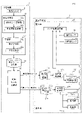
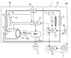
- FIG. It is a functional block diagram which shows the air conditioning system of Embodiment 1.
- FIG. It is a schematic diagram which shows the hardware configuration of the air conditioning system of Embodiment 1.
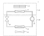
- FIG. It is a schematic diagram which shows the refrigerating cycle of the air conditioner of Embodiment 1.
- FIG. It is sectional drawing which shows the indoor unit of the air conditioner of Embodiment 1.
- FIG. It is sectional drawing which shows the heat exchanger provided in the indoor unit of the air conditioner of Embodiment 1.
- FIG. It is a schematic diagram which shows the state which the indoor unit of the air conditioner of Embodiment 1 is installed in the room. It is a schematic diagram which shows the example of the room air flow at the time of heating operation by the air conditioner of Embodiment 1.
- FIG. It is a schematic diagram for demonstrating the airflow control of the air conditioner of Embodiment 1.
- FIG. It is a schematic diagram which shows the sensor provided in the indoor unit of the air conditioner of Embodiment 1.
- FIG. It is a schematic diagram which shows the room where the indoor unit of the air conditioner of Embodiment 1 is installed.
- FIG. This is an example of a sensor item table used for learning the learning device of the first embodiment.
- It is a flowchart for demonstrating the learning method of the learning apparatus of Embodiment 1.
- FIG. It is a schematic diagram which shows the measurement point of the temperature used for the air conditioning system of Embodiment 1.
- FIG. It is a schematic diagram which shows the angle of the wind direction used for the air conditioning system of Embodiment 1.
- FIG. It is a table which shows an example of the'state'defined by the learning apparatus of Embodiment 1.
- FIG. This is an example of a Q-Table created by the learning device of the first embodiment.
- It is a schematic diagram which shows the measurement point of the temperature used for the air conditioning system of Embodiment 1.
- FIG. It is a functional block diagram which shows the air conditioning system of Embodiment 2.
- FIG. This is an example of a sensor item table created by the learning device of the third embodiment.
- Embodiment 1 The learning device of the first embodiment, the air conditioning system provided with the learning device, and the learning method of controlling the control of the air conditioner will be described with reference to FIGS. 1 to 18.
- FIGS. 1 to 18 In the first embodiment, an example of learning temperature uniform control for reducing the temperature difference between the upper and lower parts of the room by using an air conditioner provided with a temperature sensor and a thermal image sensor will be described, but the present invention is not limited to this. do not have.
- FIG. 1 is a functional block diagram showing an air conditioning system 100 of the present embodiment.
- FIG. 2 is a schematic diagram showing a hardware configuration of the air conditioning system 100.
- the air conditioning system 100 of the present embodiment includes an air conditioner 1 and a learning device 3.
- the air conditioner 1 has an indoor unit 10 and an outdoor unit 20.
- the learning device 3 learns the control method of the air conditioner 1 based on the information of the sensor or the like provided in the air conditioner 1. The details of the learning device 3 will be described later, but in the hardware configuration shown in FIG. 2, the learning device 3 is mounted on the communication terminal 5.
- FIG. 3 is a schematic diagram showing the refrigeration cycle of the air conditioner 1.
- the air conditioner 1 includes one indoor unit 10 and one outdoor unit 20.
- the indoor unit 10 has a heat exchanger 11 and a fan 12.
- the outdoor unit 20 has a heat exchanger 21, a fan 22, a compressor 23, and an expansion valve 24.
- the air conditioner 1 constitutes a refrigeration cycle as a whole with such a configuration.
- the temperature of the heat exchanger 11 and the heat exchanger 21 is adjusted by adjusting the temperature of the refrigerant according to the rotation speed of the fan 12 of the indoor unit 10 and the fan 22 of the outdoor unit 20, the rotation frequency of the compressor 23, and the opening degree of the expansion valve 24. It can be changed by doing.
- the temperature control of the heat exchanger performed by adjusting the rotation speed of the fan, the rotation frequency of the compressor, and the opening degree of the expansion valve is referred to as "refrigeration cycle control".
- one of the heat exchanger 11 provided in the indoor unit 10 and the heat exchanger 21 provided in the outdoor unit 20 constitutes an evaporator, and the other constitutes a condenser.
- the air conditioner 1 has a four-way valve 25 (not shown in FIG. 3) for switching the operation between the heat exchanger constituting the evaporator and the heat exchanger constituting the condenser. You can switch between heating operation and cooling operation.
- FIG. 4 is a cross-sectional view showing the indoor unit 10 of the air conditioner 1.
- a wall-mounted room air conditioner is shown as an example.
- the indoor unit 10 has wind direction control plates 13 and 14 for controlling the ventilation direction in addition to the heat exchanger 11 and the fan 12.
- the wind direction control plate 13 controls the wind direction in the vertical direction.
- the wind direction control plate 14 controls the wind direction in the left-right direction. That is, the indoor unit 10 has two types of wind direction control plates (upper and lower) 13 and wind direction control plates (left and right) 14.
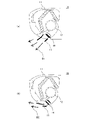
- FIG. 4A is a diagram in which the blown wind B1 blown from the blowout port is controlled to be downward by adjusting the angle of the wind direction control plate (up and down) 13.
- FIG. 4B is a diagram in which the blown wind B2 blown from the blowout port is controlled to be in the horizontal direction by adjusting the angle of the wind direction control plate (up and down) 13.
- the wind direction of the blown wind at the outlet can be controlled by adjusting the angles of the wind direction control plates 13 and 14.
- the air volume of the blown wind can be controlled by adjusting the rotation speed of the fan 12. In the following, such control of the wind direction and volume of the blown wind will be referred to as "air flow control”.
- FIG. 5 is a cross-sectional view showing the heat exchanger 11 provided in the indoor unit 10.
- the heat exchanger 11 has a pipe 11a and fins 11b, and a refrigerant flows in the pipe 11a.
- the air taken into the indoor unit 10 by the fan 12 reaches the heat exchanger 11 from the suction port and passes between the fins 11b of the heat exchanger 11. Heat exchange occurs between the air and the refrigerant via the heat exchanger 11, and the temperature in the air flow changes.
- the temperature of the refrigerant is higher than the temperature of the air taken into the heat exchanger 11, and warm air is blown from the outlet.
- the temperature of the refrigerant is lower than the temperature of the air taken into the heat exchanger 11, and cold air is blown from the outlet.
- the temperature of the refrigerant is adjusted by the rotation speed of the fan 12 of the indoor unit 10 and the fan 22 of the outdoor unit 20, the rotation frequency of the compressor 23, and the opening degree of the expansion valve 24.
- the temperature of the heat exchanger 11 of the indoor unit 10 and the heat exchanger 21 of the outdoor unit 20 can be adjusted. That is, the temperature of the blown air in the indoor unit 10 can be controlled by adjusting the temperature of the heat exchanger 11 by "refrigeration cycle control".
- the wind direction and the air volume of the blown wind can be controlled by the "air flow control”, and the temperature of the blown wind can be controlled by the "freezing cycle control”. That is, the thermal environment in the room where the indoor unit 10 of the air conditioner 1 is installed involves two controls, “air flow control” and “refrigeration cycle control”.
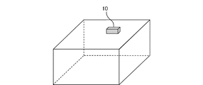
- FIG. 6 is a schematic view showing a state in which the indoor unit 10 of the air conditioner 1 is installed indoors.
- a room air conditioner will be described as an example, and an example in which one indoor unit 10 is installed on a wall in a room having a size of 16 tatami mats (width 7.2 m ⁇ depth 7.2 m ⁇ height 2.4 m). Is shown.
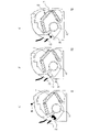
- FIG. 7 is a schematic diagram showing an example of an indoor air flow when the air conditioner 1 shown in FIG. 6 is used for heating operation.
- the temperature of the blown air is higher than the average temperature in the room. Therefore, in the room, the region of warm air in FIGS. 7A to 7C, that is, the region shown by the blown winds B3, B4, and B5 is a region having a higher temperature than the other regions.
- the vertical wind direction of the blown wind B3 is controlled horizontally by the wind direction control plate (up and down) 13, and the left and right wind direction is controlled in the front direction by the wind direction control plate (left and right) 14. It is controlled.
- the blown wind B3 directly hits the wall on the opposite side where the indoor unit 10 is installed indoors.
- the vertical wind direction of the blown wind B4 is controlled downward by the wind direction control plate (up and down) 13, and the left and right wind direction is controlled in the front direction by the wind direction control plate (left and right) 14. It is controlled.
- the vertical wind direction of the blown wind B5 is controlled downward by the wind direction control plate (up and down) 13, and the left and right wind direction is controlled by the wind direction control plate (left and right) 14 on the paper surface. It is controlled to the right toward.
- air flow control can be realized by controlling the wind direction control plates 13 and 14 and controlling the fan 12 of the indoor unit 10 as described above. Even if the air conditioner 1 is in another form such as a floor-standing method or a ceiling-embedded method, the configuration in which the temperature-adjusted air is blown from the air outlet does not change, so that the wind direction and the air volume are controlled in the same manner. As a result, "air flow control" can be realized.
- Airflow control has two main roles, which will be explained below.
- the first role of "air flow control” is to adjust the sensible temperature.
- the human sensible temperature is largely due to the heat balance of the human body (Reference 1: “Building Thermal Environment (Yuzo Sakamoto), University of Tokyo Press, 2011”).
- the heat balance of the human body can be calculated from the temperature of the air around the human body and the heat transfer coefficient between the human body and the air flow. This heat transfer changes depending on the wind speed value that passes through the surface of the human body.
- air flow control In order to improve comfort by such a sensible temperature, it is preferable to adjust the air flow for each part of the human body in "air flow control". In order to control the airflow according to the parts such as limbs and head, it is necessary to adjust the ventilation position with an accuracy of about 20 cm. For such fine "air flow control", it is desirable to use an air conditioner equipped with a high-resolution thermal image sensor, an image sensor, or the like.
- FIG. 8A is a schematic view showing the intrusion of cold air C1 from the door in the room where the indoor unit 10 of the air conditioner 1 is installed.
- FIG. 8A shows the intrusion of cold air C1 from the door in the room where the indoor unit 10 of the air conditioner 1 is installed.
- the space closed from the outside as shown in FIG. 7, as shown in FIG. 8 there is heat intrusion and heat leakage due to ventilation when the windows and doors are opened and closed.
- the wind direction is controlled in the same manner as in FIG. 7 (b), and the blown air B4, which is warm air, is blown toward the center of the room. In this case, it is possible to suppress the outflow of the blown air B4, which is the warm air from the opened door, and raise the temperature in the room.
- the wind direction is controlled in the same manner as in FIG. 7 (c), and the blown wind B5, which is warm air, is blown toward the direction in which the open door is located. In this case, the blown wind B5 flows out from the door to the outside, which hinders the temperature rise in the room. In this way, by designating an appropriate airflow area by "airflow control", it is possible to suppress airflow that is difficult to lead to temperature control in the room, and it is possible to contribute to reduction of power consumption.
- airflow control contributes to improving user comfort and reducing the power consumption of the air conditioner.
- hot air or cold air blown air is not blown to an area where there is no user. It is effective to select the ventilation area such as.
- the temperature distribution and the wind speed distribution in the room are measured, the measurement data is collected, and the wind direction, the air volume, and the temperature of the blown wind are tuned using the measurement data. Is required.
- the indoor thermal environment is related to "air flow control" by an air conditioner, heat intrusion from the outside, and heat leakage to the outside, and these form the temperature distribution and wind speed distribution in the room.
- FIG. 9A shows an indoor unit 10 provided with a temperature sensor 43 in the vicinity of the heat exchanger 11 of the indoor unit 10.
- the comfort of the user is determined by the temperature t of the air in the vicinity of the user and the wind speed v, which can be grasped by measuring the temperature distribution and the wind speed distribution in the room.
- the energy-saving performance of the air conditioner is determined by the temperature distribution and wind speed distribution of the indoor air.
- the temperature sensor 43 provided in the heat exchanger 11 can only measure the air suction temperature in the indoor unit 10, and measures the temperature and wind speed in the vicinity of the user and the temperature distribution and wind speed distribution in the entire room. Can not do it.
- the user's comfort and power consumption can be reduced by estimating the temperature in the vicinity of the user, the temperature distribution in the room, etc. by adding some correction to the measured suction temperature. Can be controlled in consideration of.
- FIG. 9B shows an indoor unit 10 provided with a thermal image sensor 44.
- the thermal image sensor 44 By providing the thermal image sensor 44 at the lower part of the indoor unit 10, the temperature distribution of the floor surface in the room can be measured. Therefore, by having such a thermal image sensor 44, it is possible to detect heat leakage in the room by the temperature distribution of the floor surface or the wall surface. In addition, the position and temperature of the human body can be detected from the captured thermal image.
- FIG. 9C shows an indoor unit 10 provided with an image sensor 45.
- the high-resolution image sensor 45 By using the high-resolution image sensor 45, it is possible to measure three-dimensional information such as the user, the position of the window, the shape of the room, and the like. In addition, the position of the user in the room can be detected.
- the image sensor 44 or the image sensor 45 is mounted on the air conditioner 10.
- the indoor unit 10 of the air conditioner 1 including the temperature sensor 43 and the thermal image sensor 44 will be described below as an example.
- FIG. 10 shows a room in which an indoor unit 10 equipped with a thermal image sensor 44 is installed.
- the thermal image sensor 44 is not shown.
- the indoor unit 10 of the air conditioner 1 is in a heating operation, and as shown in FIG. 10 (a), the blown wind B6 is directed toward the lower blow and blown to the floor surface.
- the air is blown to the lower side like the blown air B6, the warm air is blown to the floor surface, so that the temperature near the floor surface becomes high.
- warm air is not blown to the ceiling surface, the temperature of the ceiling surface becomes low.
- the temperature distribution in the vertical direction in the room may increase the temperature difference between the user's head and feet, which may cause discomfort to the user.
- the international standard for thermal environment (ISO7730) describes data on the dissatisfaction rate due to the temperature difference between the top and bottom of the room, and the recommended range is within 3 ° C. of the temperature difference between the top and bottom.
- FIG. 10B shows the floor surface temperature taken by the thermal image sensor 44, and visualizes the temperature distribution of the blown air on the floor surface in FIG. 10A.
- the thermal image sensor 44 is, for example, an infrared array sensor, which is composed of 32 ⁇ 32 image pickup elements, captures the temperature of an object surface such as a floor surface or a wall surface in a room, and controls the infrared sensor. By the edge detection mounted on the element, it is possible to extract the temperature distribution of the floor surface, the wall surface on the left and right sides and the opposite side surface from the indoor unit, and the ceiling surface.
- the high temperature area 44a shown in FIG. 10B is a region warmed by the blown wind B6. In this way, by using the thermal image sensor 44, it is possible to visualize the temperature distribution in the room.
- FIG. 11 is a schematic view showing how the wind direction of the blown wind B7 is changed in the vertical direction.
- the vertical temperature difference does not decrease if the wind direction of the blown wind B6 is fixed downward as shown in FIG. 10 (a). Therefore, as shown in FIG. 11, by changing the wind direction angle in the vertical direction of the blown wind B7, the blowing point of the blown wind B7 is not fixed to one place, and the vertical temperature difference in the room can be made uniform. can. More specifically, by controlling the operation of the wind direction control plate (up and down) 13, the wind direction of the blown wind B7 can be changed in the vertical direction, whereby the vertical temperature difference in the room can be made uniform.
- the learning device 3 receives sensor information from a target input unit 31 into which an operating target of the air conditioner 1 is input, observes the state of the thermal environment in the installation room of the air conditioner, and also observes the state of the thermal environment.
- the state observation unit 32 that selects the sensor to be used and generates the state function, and the optimum control rules of "air flow control” and "refrigeration cycle control” to achieve the operation target given to the air conditioner from the state of the thermal environment.
- the learning unit 33 on which the machine learning algorithm to be learned is implemented, the control rule storage unit 34 that stores the "air flow control rule” and the "refrigeration cycle control rule” learned in the learning unit 33, and the air conditioner 1's air flow control rule.
- a control rule transmission unit 35 for transmitting to the control rule storage unit 17a and the refrigeration cycle control rule storage unit 27a is provided.
- the learning device 3 is a device that receives sensor information from the air conditioner 1 to define the'state'of the thermal environment in the room where the air conditioner 1 is installed, and learns appropriate control according to the'state'. Therefore, learning control by reinforcement learning algorithm is implemented.
- the airflow control rule storage unit 17a provided in the indoor unit 10 of the air conditioner 1 receives and stores the "airflow control rule" from the control rule transmission unit 35.
- the indoor unit control unit 17b controls the rotation speed of the fan 12 of the indoor unit 10 and the angles of the wind direction control plates 13 and 14 based on the "airflow control rule" stored in the airflow control rule storage unit 17a. That is, when a new "airflow control rule" is input and stored from the control rule transmission unit 35 of the learning device 3 to the airflow control rule storage unit 17a, the fan 12 and the wind direction of the indoor unit 10 are controlled by the indoor unit control unit 17b.
- the control rules of the plates 13 and 14 can be changed.
- the indoor unit control unit 17b determines control based on the "air flow control rule", and then outputs information on the rotation speed of the fan 12 of the indoor unit 10 and the angles of the wind direction control plates 13 and 14 to the sensor information transmission unit 41. do.
- the sensor information transmission unit 41 transmits information on the rotation speed of the fan 12 and the angles of the wind direction control plates 13 and 14 to the state observation unit 32 of the learning device 3.
- the refrigeration cycle control rule storage unit 27a provided in the outdoor unit 20 of the air conditioner 1 receives and stores the "refrigeration cycle control rule" from the control rule transmission unit 35 of the learning device 3.
- the outdoor unit control unit 27b controls the rotation speed of the fan 22, the rotation speed of the compressor 23, and the opening degree of the expansion valve 24. That is, when a new "refrigeration cycle control rule" is input and stored from the control rule transmission unit 35 of the learning device to the refrigeration cycle control rule storage unit 27a, the fan 22 of the outdoor unit 20 is rotated by the outdoor unit control unit 27b.
- the control rules for the number, the number of revolutions of the compressor 23, and the opening degree of the expansion valve 24 can be changed.
- the outdoor unit control unit 27b determines the control based on the "refrigeration cycle control rule", and then obtains information on the rotation speed of the fan 22 of the outdoor unit 20, the rotation speed of the compressor 23, and the opening degree of the expansion valve 24. It is output to the sensor information transmission unit 41 of the indoor unit 10.
- the sensor information transmission unit 41 transmits information on the rotation speed of the fan 22, the rotation speed of the compressor 23, and the opening degree of the expansion valve 24 to the state observation unit 32 of the learning device 3.
- the air conditioning system 100 includes a microcomputer 17 provided in the indoor unit 10 of the air conditioner 1 and a microcomputer 27 provided in the outdoor unit 20. Further, the air conditioning system 100 includes a communication terminal 5 which is an input / output terminal (I / O terminal) as an external terminal having a configuration separate from that of the air conditioning machine 1, and the communication terminal 5 has a microcomputer 52. .. In the air conditioning system 100, the hardware resources are controlled by the microcomputer 17, the microcomputer 27, and the microcomputer 52.
- microcomputer in the present disclosure is an abbreviation for a microcomputer, and means a microcomputer having a CPU (Central Processing Unit) and a memory in its internal configuration.
- the microcomputer 17, the microcomputer 27, and the microcomputer 52 do not necessarily have to be composed of a “microcomputer”, and may be hardware having a processor and a memory such as a CPU.
- the microcomputer 17 provided in the indoor unit 10 controls the operation of the fan 12 and the wind direction control plates 13 and 14 of the indoor unit 10. That is, the function of the airflow control rule storage unit 17a shown in FIG. 1 can be realized by the memory of the microcomputer 17, and the function of the indoor unit control unit 17b can be realized by the CPU of the microcomputer 17. Further, the sensor information transmission unit 41 shown in FIG. 1 is also mounted on the microcomputer 17 of the indoor unit 10 shown in FIG.
- the microcomputer 27 provided in the outdoor unit 20 controls the fan 22, the inverter 23a and the motor 23b for driving the compressor 23, the expansion valve 24, and the four-way valve 25. Further, the microcomputer 27 receives measurement data from the temperature sensor 26 that measures the temperature of the heat exchanger 21, and adjusts the control values of the control of the fan 22, the compressor 23, and the expansion valve 24 based on the measurement data. ..
- the function of the refrigerating cycle control rule storage unit 27a shown in FIG. 1 can be realized by the memory of the microcomputer 27, and the function of the outdoor unit control unit 27b can be realized by the CPU of the microcomputer 27.
- the power supply 71 electrically connected to the inverter 23a of the compressor 23 shown in FIG. 2 is not included in the configuration of the air conditioner 1.
- the microcomputer 17 of the indoor unit 10 stores in advance the "air flow control rule” which is the control logic for performing the "air flow control”
- the microcomputer 27 of the outdoor unit 20 stores the "refrigeration cycle control”.
- the "refrigeration cycle control rule”, which is the control logic for performing the above, is stored in advance. Then, when the "air flow control rule” and the “refrigeration cycle control rule” are newly created or updated by the learning of the learning device 3, a new control rule is added to the microcomputer 17 and the microcomputer 27, or a new control is performed. It will be rewritten into a rule.
- the learning device 3 is mounted on the communication terminal 5 shown in FIG. More specifically, the function of the target input unit 31 of the learning device 3 shown in FIG. 1 can be realized by the I / O 51 which is the input / output unit of the communication terminal 5. Further, the functions of the state observation unit 32 and the learning unit 33 of the learning device 3 shown in FIG. 1 can be realized by the CPU of the microcomputer 52, and the functions of the control rule storage unit 34 can be realized by the memory of the microcomputer 52.
- the communication terminal 5 has sufficient computing power to execute the calculation of the learning device 3, and is a high computing power device such as a smartphone or a tablet terminal. As shown in FIG. 2 by Wi-Fi or the like, the communication terminal 5 is an indoor unit. It is configured to be able to communicate with 10 microcomputers 17.
- the input / output between the communication terminal 5 and the microcomputer 27 of the outdoor unit 20 is actually performed via the microcomputer 17 of the indoor unit 10, but in FIG. 1, it is schematically learned. It is shown that the input is directly input from the control rule transmission unit 35 of the apparatus 3 to the refrigeration cycle control rule storage unit 27a of the outdoor unit 20.
- each configuration of the learning device 3 will be described in detail.
- Reinforcement learning observes the state of the air conditioner at regular intervals, executes three learning processes: (1) action selection, (2) reward calculation, and (3) state function update, and controls logic.
- the state function that becomes is rewritten.
- the state at time t is st
- the action is at
- the reward value is rt
- the state function is the function Q ( st , at ) of st and at.
- the target input unit 31 is mounted on the I / O 51 of the communication terminal 5 shown in FIG. 2, and the operation target is input by the user's operation or the like using the communication terminal 5. Since the air conditioner 1 usually includes a remote controller (not shown) which is a dedicated terminal for operating the operation of the air conditioner 1 in addition to the indoor unit 10 and the outdoor unit 20, the target input unit 31 is the subject. The operation target input to the remote controller may be received.
- the remote controller is configured to be able to send and receive signals to and from the air conditioner 1 by an infrared sensor or the like.
- the operating target of the air conditioner 1 is, for example, "temperature uniform control” or the like, which is selected by the user's operation or the like. More specifically, for example, a selection menu such as “uniform temperature control (no unevenness)” or “reduction of power consumption (energy saving)” is created on the display unit of the communication terminal 5 or the remote controller so that the user can select it. do.
- a selection menu such as "uniform temperature control (no unevenness)” or “reduction of power consumption (energy saving)” is created on the display unit of the communication terminal 5 or the remote controller so that the user can select it. do.
- the target input unit 31 transfers the input driving target to the state observation unit 32 of the learning device 3, as shown in FIG. Output.
- the state observation unit 32 observes the state of the room in which the air conditioner 1 is placed from the sensor information, defines the'state', and outputs the state function to the learning unit 33. In order to use it for learning of the learning device 3, it is necessary to convert the observation data observed by the sensor into a'state', and the state observation unit 32 is in a state so that the'state'is uniquely determined from the observation data of the sensor. Configure the definition method.
- the state observation unit 32 has a utilization sensor selection unit 32a and a state function generation unit 32b.
- the utilization sensor selection unit 32a has a function of checking the types and resolutions of various sensors such as the temperature sensor 43 and the thermal image sensor 44 mounted on the air conditioner 1 to which sensor information is input from the sensor information transmission unit 41. It has a function to absorb the difference in the sensor specifications of the air conditioner 1.
- FIG. 12 is a sensor item table used for the function of the used sensor selection unit 32a in the state observation unit 32.
- a temperature sensor, a humidity sensor, a thermal image sensor, an image sensor, a door sensor, a humidifier, a dehumidifier, a ventilation fan, and a circulator are set as sensor items, and the mounting specifications (sensor presence / absence, sensor) for each sensor item. It is possible to record the number of mounted sensors and sensor resolution). It should be noted that what is recorded here is a sensor provided so as to be able to directly or indirectly communicate with the learning device 3.
- the sensor item table uses a communication terminal 5 that functions as an input / output terminal (I / O terminal) of the air conditioner 1 as shown in FIG. 2, and the type of sensor in which the user is indoors. It can be created by inputting specifications such as number and resolution.
- the user can create a sensor item table without inputting specifications and the like.
- home automation standards OpenHAB, HomeAssist, etc.
- devices that can be connected by home automation include various home appliances and sensors such as air conditioners, air purifiers, lights, cameras, televisions, speakers, temperature sensors, humidity sensors, and door sensors.
- air conditioners air purifiers
- lights lights
- cameras televisions
- speakers temperature sensors
- humidity sensors and door sensors.
- a temperature sensor, a humidity sensor, a thermal image sensor, an image sensor, and a door sensor are registered as sensors that can be used for observing the thermal environment, and the surroundings that affect the operation of the air conditioner are registered.
- Humidifiers, dehumidifiers, circulators, and ventilation fans are registered as equipment. This is because, if these sensors and peripheral devices are taken into consideration, even if the specifications of the air conditioner or the environment in the installation room change, it is considered that the difference in the sensor specifications can be sufficiently coped with.
- the selection of sensors and peripherals here is an example, and if the sensors that can be used for observing the thermal environment and the peripherals that affect the operation of the air conditioner are selected, other sensor items are included. It may be used, or it may be the one excluding a part of the above-mentioned items.
- the user can connect the sensor and peripheral device in the room to the air conditioner 1 by using Bluetooth, Wi-Fi, or the like. ..
- Information about the sensor and peripheral devices connected to the air conditioner 1 in this way is transmitted to the state observation unit 32 of the learning device 3.
- the state observation unit 32 sequentially adds new sensor information to the used sensor selection items. By describing the sensor information in the sensor selection item in this way, the user can create the sensor item table shown in FIG. 12 without creating the item table of the sensor to be used.
- the standard is set so that the information is stored in advance on the sensor side and transmitted to the learning device 3 on the communication protocol of home automation. be able to.
- the sensor item table can be created based on the information including the specifications of each sensor.
- the state function generation unit 32b has a function of generating a state function Q ( st , at) which is a control logic based on the information of the sensor determined to be available by the utilization sensor selection unit 32a. Reinforcement learning requires a state st that can uniquely define the environment at time t . Therefore, the state function generation unit 32b constructs a method of defining the state st using the information of the sensor determined to be available. In addition, reinforcement learning requires action options at at time t . Therefore, the state function generation unit 32b constructs a method for defining the action option at.
- the state function generation unit 32b has a state function Q ( st , at) based on the operation target input from the target input unit 31 and the sensor items determined to be available by the use sensor selection unit 32a.
- Q-Table which is a table for recording numerical values
- the state function Q ( st , at) will be described as an example, but it is possible to record the value of the action and the state. If possible, for example, a Gaussian process function, a deep learning neural network, or the like may be used.
- the learning unit 33 has a reward calculation unit 33a and a learning update unit 33b.
- the learning unit 33 learns the control rules of the "air flow control rule” and the "refrigeration cycle control rule” by using the Q-Table of the state function Q ( st , at) input from the state observation unit 32. Update.
- the reward calculation unit 33a calculates the reward value. Reinforcement learning requires reward values to assess goal achievement. Further, the learning update unit 33b updates the control rule by calculating the state function Q ( st , at) and entering the calculated value in the Q-Table. That is, the learning unit 33 is a trained model for inferring the control method of the air conditioner 1 by using the state function Q (st, at) generated by the state function generation unit 32b of the state observation unit 32. Generate a control rule that is. The details of the learning method in the learning unit 33 will be described later.
- the control rule storage unit 34 is input with the control rule updated by the learning unit 33, and stores the "air flow control rule” and the "refrigeration cycle control rule”, respectively.
- the control rule transmission unit 35 is mounted on the microcomputer 52 of the communication terminal 5 shown in FIG.
- the control rule transmission unit 35 may be mounted on a communication unit (not shown) or an I / O 51 provided as a configuration separate from the microcomputer 52 of the communication terminal 5.
- the control rule transmission unit 35 inputs a state function which is a control rule stored in the control rule storage unit 34 of the learning device 3, and inputs the state function into the “air flow control rule” and the “refrigeration cycle control rule”. , And then output to the airflow control rule storage unit 17a and the refrigeration cycle control rule storage unit 27a, and rewrite the control logic stored in the memory of the microcomputer 17 and the microcomputer 27.
- FIG. 13 is a flowchart for explaining a control method of the air conditioning system 100 of the present embodiment.
- the control method will be described with reference to FIG.
- an example in which "uniform temperature control" is input to the target input unit 31 as an operation target and wind direction control for reducing the temperature difference between the upper and lower sides of the room in "air flow control" is learned by reinforcement learning will be described. It is not limited to this.
- “uniform temperature control” is input to the target input unit 31 as the operating target of the air conditioner 1 (step S101).
- the target input unit 31 outputs the input operation target “temperature uniform control” to the state observation unit 32 of the learning device 3.
- the use sensor selection unit 32a of the state observation unit 32 acquires sensor information by input from the sensor information transmission unit 41 of the indoor unit 10 of the air conditioner 1 (step). S102). At this time, the sensor information provided so as to be communicable with the air conditioner 1 is transmitted from the sensor information transmission unit 41.
- the used sensor selection unit 32a compares the acquired sensor information with the sensor items entered in the sensor item table of the used sensor selection unit 32a, and determines whether or not there is a change in the available sensor (step). S103).
- the used sensor selection unit 32a determines that there is a change in the available sensor (step S103: Yes), and creates a sensor item table. (Step S104).
- the sensor item table shown in FIG. 12 is created in step S104, and the information of the temperature sensor 43 and the thermal image sensor 44 included in the air conditioner 1 as usable sensors is entered in the sensor item table. And.
- step S103 it is determined whether or not there is a change in the sensor that can be used in step S103, but the present invention is not limited to this, and for example, an image sensor is used in the installation room of the air conditioner. It may also be determined whether or not there is a change in the size, and if there is a change, the process may proceed to step S104 in the same manner. By doing so, even when the installation environment changes significantly due to moving or the like, an appropriate sensor can be selected and the state function can be updated.
- the sensor selection unit 32a uses the created sensor item table information and the operation target information input from the target input unit 31 (in the present embodiment, “temperature uniform”. Based on the control "), the usage sensor actually used for learning is selected (step S105).
- the temperature sensor and the thermal image sensor which are the available sensors shown in the sensor item table shown in FIG. 12, are all necessary for "temperature uniform control", the temperature sensor and the thermal image are used. Determine to include the sensor in the utilization sensor. Then, the utilization sensor selection unit 32a outputs the information of the temperature sensor and the thermal image sensor selected as the utilization sensor to the state function generation unit 32b.
- the operation target is input to the state observation unit 32 from the target input unit 31, if the input operation target is "temperature uniform control", control is performed for the purpose of temperature uniformity. Is required. Further, here, “temperature uniform control” only needs to be able to make the temperature uniform, and humidity is not a control item. Therefore, even if the air conditioner 1 is equipped with a humidity sensor and the mounting specification "1 piece" is entered for the humidity sensor item in the sensor item table, the "uniform temperature control” includes the humidity sensor. No need to use. Therefore, in this case, the utilization sensor selection unit 32a excludes the humidity sensor in the selection of the utilization sensor.
- the utilization sensor selection unit 32a selects the sensor necessary for control for achieving the operation target input to the target input unit 31, and outputs the information of the selected sensor to the state function generation unit 32b.
- the state function generation unit 32b When the information of the utilization sensor is input from the utilization sensor selection unit 32a, the state function generation unit 32b generates a state function (step S106).
- a state function (step S106)
- the state function generation unit 32b defines the state st using the information of the sensor determined to be available.
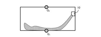
- FIG. 14 is a cross-sectional view showing measurement points in the room where the indoor unit 10 of the air conditioner 1 is installed.
- FIG. 14 shows temperature measurement points P 1 , P 2 , and P 3 , which are part of the data measured by the thermal image sensor 44.
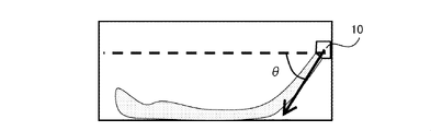
- FIG. 15 is a cross-sectional view showing the wind direction angle ⁇ in the vertical direction of the blown wind of the indoor unit 10 of the air conditioner 1.
- the blowing angle ⁇ can be stored as sensor information by recording the angle of the stepping motor that controls the operation of the wind direction control plate 13 in the microcomputer 17 of the indoor unit 10.
- "uniform temperature control" is selected, and the temperature value of the measurement point on the wall surface measured by the thermal image sensor 44 is used by the state observation unit 32 as described later.
- the state function generation unit 32b has selected representative measurement points P1, P2 , P3 and a blower angle of the temperature at which a part of the data measured by the thermal image sensor 44 is selected.
- the definition of'state'can be extended. For example, by setting the number of temperature measurement points to 4 or more, the'state'can be defined in more detail. Further, by expanding the discrimination of the blowing angle ⁇ to three or more ways, it is possible to define the'state'more finely.
- the three points shown in FIG. 14 are shown.
- Measurement is necessary and sufficient.
- the measurement temperatures at the measurement points P 1 , P 2 , and P 3 shown in FIG. 14 are T P 1 , T P 2, and T P 3, respectively.
- the blowing angle ⁇ of the blowing wind shown in FIG. 15 is classified into two cases, that is, the case of the upper blowing of ⁇ ⁇ 45 ° and the case of the lower blowing of ⁇ ⁇ 45 °.
- s 1 T P1 > T P2 > T P3 and ⁇ ⁇ 45 ° s 2 : T P1 > T P2 > T P3 and ⁇ ⁇ 45 ° s 3 : T P1 > T P3 > T P2 and ⁇ ⁇ 45 ° s 4 : T P1 > T P3 > T P2 and ⁇ ⁇ 45 ° s 5 : T P2 > T P1 > T P3 and ⁇ ⁇ 45 ° s 6 : T P2 > T P1 > T P3 and ⁇ ⁇ 45 ° s 7 : T P2 > T P3 > T P1 and ⁇ ⁇ 45 ° s 8 : T P2 > T P3 > T P1 and ⁇ ⁇ 45 ° s 9 : T P3 > T P1 > T P2 and ⁇ ⁇ 45 ° s 10 : T P3 > T P3 > T
- the state function generation unit 32b defines the action option at.
- "uniform temperature control” is set as an operating target, and what is required for uniforming the temperature difference between the upper and lower sides is wind direction control and temperature control of the blown wind.
- wind direction control of the blown wind select from three ways of raising, lowering, and not changing the wind direction angle
- temperature control of the blown wind select from three ways of raising, lowering, and not changing the temperature. do.
- the blowing angle in the state st is ⁇ t
- the frequency of the compressor is ft
- the opening degree of the expansion valve is ⁇ t
- the action options a t + 1 are the following 6 ways a 1 to a 6 . Conceivable.
- a 1 to a 3 are a kind of wind direction control, that is, "air flow control”.
- ⁇ is an adjustment angle of the blowout angle in the vertical direction
- ⁇ 5 °.
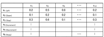
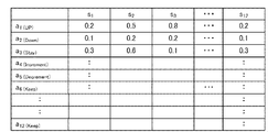
- the state function generation unit 32b generates a state function that records the value when the action ai is selected in the state s i .
- 4 to a6 are a kind of temperature control, that is, “freezing cycle control”.
- the frequency f of the compressor is raised and the opening degree ⁇ of the expansion valve is lowered.
- the frequency f of the compressor is lowered and the opening degree ⁇ of the expansion valve is raised.
- ⁇ f is a constant for adjusting the frequency of the compressor
- ⁇ is a constant for adjusting the opening degree of the expansion valve.
- FIG. 17 is a state function Q ( st , at) of the present embodiment.
- the state function generation unit 32b outputs the state function created in this way to the learning unit 33 (step S107).
- step S107 When the state function is input from the state function generation unit 32b (step S107), or when it is determined that there is no change in the sensor specifications (step S103: No), the state observation unit 32 observes the state (step S107). Step S108).
- FIG. 18 is a cross-sectional view showing measurement points in the room where the indoor unit 10 of the air conditioner 1 is installed.
- the measurement points Q1 and Q2 shown in FIG. 18 are temperature target setting points used for calculating the reward value by the reward calculation unit 33a. That is, in the example of this embodiment, the state observation unit 32 observes the floor surface temperature T Q1 and the ceiling surface temperature T Q 2 by inputting the measured value by the thermal image sensor 44 from the sensor information transmission unit 41.
- the reward calculation unit 33a of the learning unit 33 calculates the reward value based on the input'state'(step S109). ). Specifically, the reward calculation unit 33a calculates the reward value rt using the following equations 3 and 4.
- the learning update unit 33b calculates the state function Q ( st , at) using the following equation 5, and updates the control rule by writing the calculated value in the Q-Table (step). S110).
- equation 5 shows the update by the Q-learning method.
- ⁇ is the learning rate (0 to 1)
- ⁇ is the discount rate (0 to 1).
- the learning unit 33 determines whether or not to end the learning (step S111). Specifically, at the time of manufacturing the air conditioner 1, it is possible to set the learning to end when the preset learning period elapses. In this case, for example, the learning period is set to 5 days, and it is determined that the learning ends when the number of days 5 days or more elapses from the date at the start of learning. Further, it may be determined that the learning is terminated when the fluctuation of the state function Q (s, a) becomes small.
- the fluctuation value ⁇ of the learning of the state function is set, and if the state function Q ( si , a j ) ⁇ in all si and a j , it is within the preset learning period. Also determines the end of learning as the learning is completed. If the learning is not completed (step S111: No), the process returns to step S108 and the observation of the state is continued.
- control rule includes the "air flow control rule” and the "refrigeration cycle control rule".
- control rule transmission unit 35 outputs the "airflow control rule” to the airflow control rule storage unit 17a of the indoor unit 10 of the air conditioner 1, and outputs the "refrigeration cycle control rule” to the outdoor unit 20 of the air conditioner 1.
- Output to the refrigeration cycle control rule storage unit 27a step S113. This completes the update of the control rule.
- control rule is transmitted to the air conditioner 1 each time the learning is completed, but the present invention is not limited to this, and the control rule is used as long as the Q-Table does not fluctuate significantly. It may not be transmitted to the air conditioner 1.
- the criteria for whether or not to send a control rule can be set in advance.
- air flow control As mentioned above, the control of the air conditioner can be divided into “air flow control” and “refrigeration cycle control”.
- air conditioners such as room air conditioners and packaged air conditioners whose operating targets are to improve user comfort and reduce power consumption
- air flow control that has the effect of adjusting the sensible temperature is an important control.
- the air conditioning machine can detect the temperature distribution of the blown air, the thermal image sensor that can observe the intrusion of cold air, and the layout and shape of the room, in addition to the temperature sensor. It is desirable that an image sensor or the like is installed. Conventional techniques lack a machine learning interface for handling sensors such as thermal image sensors and image sensors for airflow control.
- the air conditioning system 100 and the learning device 3 of the present embodiment have the use sensor selection unit 32a and the state function generation unit 32b in the state observation unit 32, and can select the use sensor to generate the state function. can. Therefore, it is possible to perform learning by adding sensors such as a thermal image sensor and an image sensor for controlling the air flow. In addition, even if the specifications of the air conditioner are different, it has the effect of enabling general-purpose learning.
- thermal image sensor or an image sensor it is not possible to directly measure the temperature distribution or wind velocity distribution of the air in the vicinity of the user or the air in the entire room, but only the air suction temperature can be measured. Unlike, since information such as the temperature distribution of the wall surface and the floor surface, the position of the user and the shape of the room can be utilized, the comfort of the user and the estimation accuracy of the thermal environment in the room are improved. Therefore, it is desirable that a thermal image sensor or an image sensor can be used for learning.
- thermal image sensors and image sensors are expensive and increase the price of air conditioners. Further, the cost of the thermal image sensor and the image sensor increases as the resolution increases. Furthermore, even in models equipped with thermal image sensors and image sensors, the sensor specifications are not unified, and there are differences in the resolution of the sensors.
- the air conditioning system 100 and the learning device 3 of the present embodiment can support general-purpose learning.
- the processing can be executed by the microcomputer 52 mounted on the communication terminal 5, and the processing can also be executed by the microcomputer mounted on the air conditioner 1.
- the air conditioning system 100 in which the learning device 3 is provided as a configuration separate from the air conditioner 1 has been described, but the present invention is not limited to this, and the air conditioning is not limited to this.
- the learning device 3 may be provided as a part of the machine 1.
- the learning device 3 may be mounted on the microcomputer 17 of the indoor unit 10 or the microcomputer 27 of the outdoor unit 20 shown in FIG.
- the indoor unit 10 has a dedicated terminal (for example, a remote controller that is an accessory of the air conditioner) equipped with a microcomputer or the like constituting the learning device 3 as a configuration separate from the indoor unit 10 and the outdoor unit 20.
- the air conditioner may be configured from the outdoor unit 20 and the dedicated terminal.
- FIG. 19 is a functional block diagram showing the air conditioning system 200 of the present embodiment.
- the air conditioning system 200 of the present embodiment is different from the air conditioning system 100 of the first embodiment in that the humidity sensor 46 is further provided. Since the other configurations of the present embodiment are the same as those of the first embodiment, the differences will be mainly described below.
- the air conditioner 1 of the present embodiment further includes a humidity sensor 46 as a configuration of the indoor unit 10, and can control the humidity during cooling and heating.
- the humidity sensor 46 is configured to be able to output sensor information to the state observation unit 32 of the learning device 3 via the sensor information transmission unit 41.
- the utilization sensor selection unit 32a of the state observation unit 32 of the learning device 3 is shown in FIG. 12 in the preparation of the sensor item table shown in FIG. 13 (step S104). Enter the humidity sensor in the indicated sensor item table, such as "1". Then, the utilization sensor selection unit 32a selects the humidity sensor as the utilization sensor when the operation target related to the humidity control is input from the target input unit 31 (step S105). By doing so, the state function generation unit 32b can generate a Q-Table as a state function including the humidity sensor as a utilization sensor (step S106).
- the target relative humidity RH ref [%] set by the user and the relative humidity RH sensor measured by the humidity sensor [%] are set by the user as shown in the following equation 6.
- the reward value for the humidity target can be calculated using the ratio RH obtained by the formula 6, and the reward value of the humidity is added to the calculation formula of the reward value of the formula 4 to be rewarded as in the following formula 7. You can calculate the value.
- the learning device 3 since the learning device 3 has the state observation unit 32, it is possible to learn to adjust the humidity in response to the addition of the humidity sensor 46. That is, the learning device 3 has an effect of enabling general-purpose learning.
- the air conditioning system 200 having the humidity sensor 46 as the configuration of the indoor unit 10 of the air conditioner 1 has been described, but the present invention is not limited to this, and the humidity sensor is separate from the air conditioner. It may be provided as a configuration of. Even when various sensors such as a humidity sensor are provided as a configuration separate from the air conditioner, general-purpose learning is possible by providing the learning device 3 so as to be able to communicate with the learning device 3.
- FIG. 20 is a functional block diagram showing the air conditioning system 300 of the present embodiment.
- the air conditioning system 300 of the present embodiment is different from the air conditioning system 100 of the first embodiment in that it has a circulator 61 and a ventilation fan 62 as peripheral devices provided so as to be able to communicate with the learning device 3. Since the other configurations of the present embodiment are the same as those of the first embodiment, the differences will be mainly described below.
- the air conditioner 1 provided with the temperature sensor 43 and the thermal image sensor 44 is used as in the first embodiment to reduce the temperature difference between the top and bottom of the room.
- An example of learning "temperature uniform control” will be described.
- the main difference in control from the first embodiment is not only to simply reduce the temperature difference between the upper and lower temperatures in the room, but also to measure the temperature in the room with the temperature sensor 43, and the measured temperature is the air conditioner 1.
- the point is to perform "refrigeration cycle control" so that the target temperature Tr is reached.
- the target temperature of the air conditioner 1 can be set by the user using a communication terminal 5, a remote controller, or the like.
- the air conditioning system 300 includes a learning device 3 and a peripheral device 6 independent of the air conditioner 1.
- the peripheral device 6 is a circulator 61 and a ventilation fan 62.
- an air conditioning system 300 having a circulator 61 and a ventilation fan 62 is shown as an example as a peripheral device, but the present invention is not limited to this, and a humidifier, a dehumidifier, or the like may be used as the peripheral device.
- the circulator 61 and the ventilation fan 62 of the peripheral device 6 have operation information transmission units 61a and 62a capable of communicating with the learning device 3, respectively, and the fan rotation speed to the learning device 3 via the operation information transmission units 61a and 62a, respectively. It is possible to transmit driving information such as. Further, the circulator 61 and the ventilation fan 62 have fans 61b and 62b, respectively, and the fans 61b and 62b are controlled by the operation control units 61c and 62c, respectively.
- the operation control units 61c and 62c receive control signals from the control rule transmission unit 35 of the learning device 3 and output control information of the fans 61b and 62b, that is, operation information to the operation information transmission units 61a and 62a.
- FIG. 21 shows a sensor item table in which sensor items determined to be usable by the use sensor selection unit 32a of the present embodiment are entered.
- the sensor selection unit 32a of the state observation unit 32 of the learning device 3 has "1" ventilation fan and "1" circulator in the sensor item table shown in FIG. 21, as in the flowchart shown in FIG. Further fill in as "individual” (step S104). That is, in the present embodiment, one ventilation fan and one circulator are registered as peripheral devices.
- the circulator 61 creates an air flow by sucking in the air in the room and discharging it into the room. Therefore, it can assist the air flow of the air conditioner 1, and conversely, it may hinder the air flow. Here, it is assumed that the circulator 61 assists the air flow of the air conditioner 1.
- the ventilation fan 62 sucks in the indoor air and discharges it to the outside of the room. Although the air flow of the air conditioner 1 is not obstructed by the ventilation fan 62, the warm air and cold air in the room are discharged by the operation of the ventilation fan 62, which leads to an increase in the heat load for the air conditioner 1. That is, since the operating capacity required for the air conditioner 1 differs between when the ventilation fan 62 is operating and when it is not operating, it is necessary to adjust the temperature of the heat exchanger by "refrigeration cycle control" to control the temperature of the blown air. There is.
- the use sensor selection unit 32a of the learning device 3 selects the circulator 61 and the ventilation fan 62 as peripheral devices used for learning in order to learn "temperature uniform control" (step S105). .. By doing so, the state function generation unit 32b can generate a Q-Table as a state function including the circulator 61 and the ventilation fan 62 as control targets (step S106).
- FIG. 21 shows a Q-Table created by the state function generation unit 32b of the learning device 3 of the present embodiment.
- six states of the temperature ranking at the three measurement points and two states of the blowout angle ⁇ are defined as 12 states s1 to s12 .
- the same states s 1 to s 12 as in the first embodiment are defined and used for learning.
- a1 to a3 are a kind of wind direction control, that is, “airflow control” as in the first embodiment.
- a4 to a6 are a kind of temperature control, that is, “freezing cycle control” as in the first embodiment. That is, a 1 to a 6 are controls relating to the air conditioner 1.
- a 10 to a 12 control the rotation speed V of the fan 62b of the ventilation fan 62.
- the rotation speed of the fan 62b is increased, and in a11 , the rotation speed of the fan 62b is decreased. Further, in a12 , the rotation speed of the fan 62b is not changed.
- ⁇ V is a constant for adjusting the motor rotation speed of the fan 62b of the ventilation fan 62.
- the state function generation unit 32b creates the state function and then outputs the state function to the learning unit 33 (step S107).
- the temperatures of the floor surface temperature T Q1 and the ceiling surface temperature T Q2 shown in FIG. 18 are observed by the thermal image sensor 44 as in the first embodiment, and the following equations 8 and 9 are used. Use to calculate the reward value.
- T m is a suction temperature measured by the temperature sensor 43.
- ⁇ is a weighting coefficient that takes a value from 0 to 1, and is a constant for weighting evaluation of the upper and lower temperature difference and the temperature difference between the suction temperature T m and the target temperature Tr .
- the learning device 3 has the effect of enabling general-purpose learning.
- the home automation mechanism that has become widespread in recent years facilitates the expansion of sensor specifications.
- This mechanism is equipped with not only temperature sensors, thermal image sensors, image sensors, etc., but also indoor communication devices such as ventilation fans, circulators, humidifiers, dehumidifiers, and door sensors that detect the opening and closing of doors.
- indoor communication devices such as ventilation fans, circulators, humidifiers, dehumidifiers, and door sensors that detect the opening and closing of doors.
- the air conditioner can be controlled in cooperation with such peripheral devices, there is a possibility of more efficient operation for improving user comfort and reducing power consumption than using the air conditioner alone.
- the learning device needs an interface for controlling these peripheral devices in the same manner as the air conditioner and learning the control method of the air conditioner according to the indoor environment.
- FIG. 23 shows how the airflow of the circulator 61 and the airflow of the blown air of the indoor unit 10 of the air conditioner 1 interfere with each other.
- the ventilation angle ⁇ of the circulator 61 can be further added to the action options as in the following a 13 to a 15 . By doing so, it is possible to learn the wind direction of the blown wind that does not interfere with the air flow of the circulator 61.
- FIG. 24 is a functional block diagram showing the air conditioning system 400 of the present embodiment.
- the air conditioning system 400 of the present embodiment is different from the air conditioning system of the first to third embodiments in that learning can be performed by using Q-Table properly in consideration of the number of people in the room. Since the other configurations of the present embodiment are the same as those of the first or third embodiment, the differences will be mainly described below.
- the air conditioner 1 is a room air conditioner installed in a room having a size of about 10 tatami mats (18 m 2 ), and an air conditioner having a heat load capacity of about 2000 W will be described as an example. However, it is not limited to this.
- the air conditioning system 400 has the image sensor 45 described with reference to FIG. 9 (c) in the indoor unit 10 of the air conditioner 1.
- the sensor information of the image sensor 45 is transmitted to the state observation unit 32 of the learning device 3 via the sensor information transmission unit 41.
- the learning device 3 of the present embodiment has a room number counting unit 32c in the state observation unit 32.
- the indoor number counting unit 32c counts the number of users in the room where the indoor unit 10 of the air conditioner 1 is installed, based on the sensor information of the image sensor 45.
- the number of users in the room can be determined by image processing.
- the amount of heat generated by the human body is about 100 W per person, which is the heat load of the air conditioner 1.
- the operating ability of the air conditioner 1 can be adjusted. If it is a room air conditioner for a house, a room air conditioner for 10 tatami mats (18 m 2 ) has a heat load capacity of 2000 W or more.
- the number of people in the room is not considered in the learning, and the states s1 to s12 defined by the state observation unit do not include the information on the number of people in the room.
- the number of people in the room is about 1 to 2, and that an air conditioner having a heat load capacity of 2000 W or more does not significantly affect the control method.
- an air conditioner having a heat load capacity of 2000 W or more does not significantly affect the control method.
- even in a room of about 10 tatami mats (18 m 2 ) there are often cases where three or more people stay at the same time.
- the method of adjusting the reinforcement learning method according to the number of people in the room will be explained below. More specifically, in the present embodiment, two types of Q-Tables are held, one is when the number of users in the room is 2 or less, and the other is when the number of users in the room is 3 or more. Use the Q-Table to be used properly.
- FIG. 25 shows an example of Q-Table used in this embodiment.
- FIG. 25A is used when the number of users in the room is two or less, and is the same as that described in the first embodiment.
- the heat load is small, so control can be performed only by the air conditioner without using the assistance of the ventilation fan or circulator in the room.
- FIG. 25B is used when the number of users in the room is 3 or more, and the control items include the circulator 61 and the ventilation fan 62 as described in the third embodiment.
- the control items include the circulator 61 and the ventilation fan 62 as described in the third embodiment.
- the air conditioning system 400 of the present embodiment is characterized in that it has a plurality of Q-tables and is used properly, the number of Q-tables is not limited to two, but is three or more. May be good. Further, the criteria for properly using a plurality of Q-Tables may be other than the number of users.
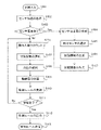
- FIG. 26 is a flowchart for explaining the learning method of the fourth embodiment. As shown in FIG. 25, the flowchart of the present embodiment is obtained by adding the processing of counting the number of people in the room (step S121) and selecting the state function (step S122) to the flowchart of FIG. 13 shown in the first embodiment. Is.
- the state function generation unit 32b generates a state function (step S107). However, in the present embodiment, the state function generation unit 32b generates two types of Q-Tables shown in FIG. 25.
- step S107 when the state function generation unit 32b outputs the state function to the learning unit 33 (step S107), or when it is determined that there is no change in the sensor specifications (step S103: No), the number of people in the room of the state observation unit 32
- the counting unit 32c counts the number of users in the room using the sensor information of the image sensor 45 input from the sensor information transmitting unit 41 (step S121).
- the indoor number counting unit 32c selects an appropriate state function based on the counting result of the indoor number of people (step S122). Information on which state function is selected is output from the state observation unit 32 to the learning unit 33.
- the state observation unit 32 observes the state as in the first embodiment (step S108).
- the subsequent flow is the same as that of the first embodiment, but when it is determined whether or not to end the learning (step S111) and when it is determined not to end the learning (step S111: No), the indoor number measurement unit 32c is performed again. The number of people in the room will be counted according to (Step S121).
- the air conditioner system 400 configured in this way, by including the number of users existing in the room in the definition of the state of the air conditioner, it is possible to adjust the operating ability of the air conditioner more than necessary. It has the effect of being able to perform fine control without increasing the Q-Table.
- Embodiment 5 The air conditioning system of the fifth embodiment will be described.
- the air conditioning system of the present embodiment is different from the air conditioning system of the first to fourth embodiments in that the learning device 3 is provided on the server. Since the other configurations of the air conditioning system of the present embodiment are the same as those of the first to fourth embodiments, the differences will be mainly described below.
- the learning device 3 does not have to be limited to being installed in a part of the communication terminal 5 or the air conditioner 1 used by the user (for example, a remote controller), and may be installed on a server via the Internet. In this case, the learning device 3 on the server can learn the operation of two or more air conditioners 1.
- the target input unit 31 of the learning device 3 is mounted on the I / O 51 of the communication terminal 5 and the target is input by the user.
- the entire learning device 3 including the target input unit 31 is provided on the server. That is, the target input unit 31 of the learning device 3 in the present embodiment has an operation target input by a communication terminal capable of communicating with the air conditioner 1 used by the user, a remote controller of the air conditioner 1, or the like. It has a function to receive the input information.
- the shape of the installation room of the air conditioner 1 is examined by processing the image captured by the image sensor 45. be able to. That is, by using the image sensor 45 to detect the floor plan in the room, defining the floor plan in the room as a state, and learning the operation of a plurality of air conditioners, the optimum airflow control and refrigeration cycle control based on the floor plan are controlled. Has the effect of being able to establish.
- Embodiment 6 The air conditioning system of the sixth embodiment is shown in FIG. 27.
- the air conditioning system of the sixth embodiment includes the sensor measurement value interpolation unit 47 that estimates the state estimated value based on the measured value of the sensor and interpolates the measured value of the sensor, and the air of the first to fifth embodiments. Different from the harmony system. Since the other configurations of the air conditioning system of the present embodiment are the same as those of the first to fifth embodiments, the differences will be mainly described below.
- Sensors such as temperature sensors and humidity sensors have different performances such as accuracy, resolution and sampling rate depending on the type of sensor.
- an inexpensive temperature sensor has a low accuracy and includes an error of ⁇ 0.5 ° C.
- an expensive temperature sensor has a high accuracy and includes an error of ⁇ 0.1 ° C., and the accuracy varies depending on the quality of the sensor.
- the resolution of the inexpensive temperature sensor is 1.0 ° C.
- the resolution of the expensive temperature sensor is 0.1 ° C.
- the sampling rate differs depending on the quality of the sensor, such as a sampling rate of 5.0 seconds for an inexpensive temperature sensor and a sampling rate of 1.0 seconds for an expensive temperature sensor.
- the air conditioning system of the sixth embodiment includes a sensor measurement value interpolation unit 47.
- the sensor measurement value interpolation unit 47 calculates the state estimation value based on the actual measurement value of each sensor by using the state estimation method, and interpolates the measurement value of the sensor.
- the sensor measurement value interpolation unit 47 may be provided in the sensor information transmission unit 41, but the arrangement is not limited to this. Further, the sensor measurement value interpolation unit 47 may collect the specifications of the accuracy, resolution, and sampling rate of the sensor, and may perform the sensor measurement value interpolation when the performance of these specification values is lower than the reference.
- the operation of the sensor measurement value interpolation unit 47 includes the following system identification step and state estimation step.
- the room temperature x (t) [° C.] can be written as Equation 10 as the outside air temperature x 0 [° C.], the heat input Q [W] by the air conditioner, and the room insulation coefficient L [W / ° C.].
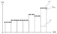
- FIG. 28 is a diagram showing temperature values when the temperature y (t) of such a room is observed by a temperature sensor having a minimum resolution ⁇ T [° C.] and a sampling rate ⁇ t [sec].
- Equation 10 is a linear first-order ordinary differential equation of temperature x (t), and can be described by a linear state-space model like Equation 11 by differentiating.
- x (k) is the state (temperature)
- Q (k) is the heat input of the air conditioner
- y (k) is the temperature value of the room measured by the sensor.
- A, b, and c are parameters of the state space model.
- Parameters (A, b, c) can be estimated by collecting data y (k) and Q (k) for a certain period at a sampling rate ⁇ t and performing system identification such as the least squares method or the N4SID method.
- the sensor measurement value interpolation unit 47 performs system identification based on the equation 11 and the data y (k) and Q (k) for a certain period, and estimates the parameters (A, b, c) of the state space model. After estimating the parameters (A, b, c), the process proceeds to the state estimation step.
- ⁇ State estimation step> In the state estimation unit step, as the room temperature value, data obtained by resampling (upsampling) the sensor temperature value observed by the temperature sensor having a sampling rate ⁇ t at a sampling rate ⁇ t up smaller than ⁇ t is used.
- FIG. 29 shows the temperature value obtained by resampling (upsampling) the sensor temperature value measured in FIG. 28 by ⁇ tup .
- the upsampling is performed by simple interpolation in which the temperature in the interval of ⁇ ⁇ t / 2 seconds of the temperature measurement time t of the sensor in FIG. 1 is set to the same value as the sensor temperature measurement value.
- the sensor value is an observed value obtained by adding white noise w (k) to the true temperature value x (k)
- the data obtained by upsampling the sensor temperature value by ⁇ tup is handled. Since the sampling rates of the temperature data handled by Equation 12 and Equation 11 are different, the discrete time is set to l instead of k.
- FIG. 30 is a diagram showing state estimates estimated from FIG. 29 by a Kalman filter.
- the sensor measurement value interpolation unit 47 estimates the state based on the equation 12 using the data obtained by re-sampling the sensor temperature value observed by the temperature sensor having the sampling rate ⁇ t at a sampling rate ⁇ t up smaller than ⁇ t, and calculates the state estimation value. Then, the sensor measurement value is interpolated using the state estimation value. Then, the data learning device 3 performs learning using the data obtained by interpolating the sensor measured value by the state estimated value.
- the resolution and sampling rate of the sensor can be complemented and the state observation accuracy can be improved. In addition, the accuracy of learning can be improved by increasing the accuracy of state observation.
- the senor is provided with a sensor measurement value interpolation unit that estimates the state estimation value based on the measurement value of the sensor and interpolates the measurement value of the sensor. It is possible to observe the state with high accuracy by complementing the resolution and sampling rate, and it is possible to improve the accuracy of learning.
Landscapes
- Engineering & Computer Science (AREA)
- Chemical & Material Sciences (AREA)
- Combustion & Propulsion (AREA)
- Mechanical Engineering (AREA)
- General Engineering & Computer Science (AREA)
- Physics & Mathematics (AREA)
- Fuzzy Systems (AREA)
- Mathematical Physics (AREA)
- Signal Processing (AREA)
- Air Conditioning Control Device (AREA)
Priority Applications (2)
| Application Number | Priority Date | Filing Date | Title |
|---|---|---|---|
| JP2022573082A JP7374349B2 (ja) | 2020-12-29 | 2021-12-27 | 学習装置、空気調和機、通信端末、空気調和システム、及び空気調和機の制御の学習方法 |
| CN202180085758.8A CN116635674A (zh) | 2020-12-29 | 2021-12-27 | 学习装置、空调机、通信终端、空调系统和空调机的控制的学习方法 |
Applications Claiming Priority (2)
| Application Number | Priority Date | Filing Date | Title |
|---|---|---|---|
| JP2020219762 | 2020-12-29 | ||
| JP2020-219762 | 2020-12-29 |
Publications (1)
| Publication Number | Publication Date |
|---|---|
| WO2022145417A1 true WO2022145417A1 (ja) | 2022-07-07 |
Family
ID=82260778
Family Applications (1)
| Application Number | Title | Priority Date | Filing Date |
|---|---|---|---|
| PCT/JP2021/048556 Ceased WO2022145417A1 (ja) | 2020-12-29 | 2021-12-27 | 学習装置、空気調和機、通信端末、空気調和システム、及び空気調和機の制御の学習方法 |
Country Status (3)
| Country | Link |
|---|---|
| JP (1) | JP7374349B2 (https=) |
| CN (1) | CN116635674A (https=) |
| WO (1) | WO2022145417A1 (https=) |
Cited By (2)
| Publication number | Priority date | Publication date | Assignee | Title |
|---|---|---|---|---|
| WO2024154929A1 (ko) * | 2023-01-19 | 2024-07-25 | 삼성전자주식회사 | 공기조화기 및 공기조화기의 제어 방법 |
| WO2025204787A1 (ja) * | 2024-03-29 | 2025-10-02 | 直人 榊原 | 温熱環境計測装置及びそれを用いた温熱環境解析方法 |
Citations (5)
| Publication number | Priority date | Publication date | Assignee | Title |
|---|---|---|---|---|
| JPH09250794A (ja) * | 1996-03-19 | 1997-09-22 | Hitachi Ltd | 空気調和機 |
| JP2019002596A (ja) * | 2017-06-12 | 2019-01-10 | 清水建設株式会社 | 温度分布計測システム、空調システム、冷却方法及びプログラム |
| WO2020184454A1 (ja) * | 2019-03-13 | 2020-09-17 | ダイキン工業株式会社 | 空調制御システム、及び、空調制御方法 |
| JP2020177492A (ja) * | 2019-04-19 | 2020-10-29 | 三菱電機株式会社 | 計画立案装置、計画立案方法及びコンピュータプログラム |
| JP2020200998A (ja) * | 2019-06-11 | 2020-12-17 | 三菱電機株式会社 | 換気装置および換気システム |
-
2021
- 2021-12-27 JP JP2022573082A patent/JP7374349B2/ja active Active
- 2021-12-27 WO PCT/JP2021/048556 patent/WO2022145417A1/ja not_active Ceased
- 2021-12-27 CN CN202180085758.8A patent/CN116635674A/zh not_active Withdrawn
Patent Citations (5)
| Publication number | Priority date | Publication date | Assignee | Title |
|---|---|---|---|---|
| JPH09250794A (ja) * | 1996-03-19 | 1997-09-22 | Hitachi Ltd | 空気調和機 |
| JP2019002596A (ja) * | 2017-06-12 | 2019-01-10 | 清水建設株式会社 | 温度分布計測システム、空調システム、冷却方法及びプログラム |
| WO2020184454A1 (ja) * | 2019-03-13 | 2020-09-17 | ダイキン工業株式会社 | 空調制御システム、及び、空調制御方法 |
| JP2020177492A (ja) * | 2019-04-19 | 2020-10-29 | 三菱電機株式会社 | 計画立案装置、計画立案方法及びコンピュータプログラム |
| JP2020200998A (ja) * | 2019-06-11 | 2020-12-17 | 三菱電機株式会社 | 換気装置および換気システム |
Cited By (2)
| Publication number | Priority date | Publication date | Assignee | Title |
|---|---|---|---|---|
| WO2024154929A1 (ko) * | 2023-01-19 | 2024-07-25 | 삼성전자주식회사 | 공기조화기 및 공기조화기의 제어 방법 |
| WO2025204787A1 (ja) * | 2024-03-29 | 2025-10-02 | 直人 榊原 | 温熱環境計測装置及びそれを用いた温熱環境解析方法 |
Also Published As
| Publication number | Publication date |
|---|---|
| JP7374349B2 (ja) | 2023-11-06 |
| JPWO2022145417A1 (https=) | 2022-07-07 |
| CN116635674A (zh) | 2023-08-22 |
Similar Documents
| Publication | Publication Date | Title |
|---|---|---|
| CN107631423B (zh) | 一种基于人体位置的空调器控制方法及空调器 | |
| CN107525237B (zh) | 一种智能空调器控制方法及智能空调器 | |
| CN112805507B (zh) | 空调机、空调机控制方法及记录介质 | |
| CN113819607A (zh) | 一种空调智能控制方法、控制装置、空调器及电子设备 | |
| WO2019024826A1 (zh) | 壁挂式空调室内机及其控制方法 | |
| US11680721B2 (en) | Systems and methods for controlling a heating and air-conditioning (HVAC) system | |
| CN109297153A (zh) | 空调器及其控制方法、控制装置、可读存储介质 | |
| CN107013978A (zh) | 空调室内机及其送风方法 | |
| CN109140713A (zh) | 空调器及其控制方法、控制装置、可读存储介质 | |
| CN109405213A (zh) | 空调器及其控制方法、控制装置、可读存储介质 | |
| JP7374349B2 (ja) | 学習装置、空気調和機、通信端末、空気調和システム、及び空気調和機の制御の学習方法 | |
| CN107575994A (zh) | 用于控制空调的方法及装置、空调 | |
| WO2021057468A1 (zh) | 空调器的滤尘网的堵塞程度的判定方法及空调器 | |
| JP7570538B2 (ja) | 学習装置、空調制御システム、推論装置、空調制御装置、学習済みモデルの生成方法、学習済みモデル及びプログラム | |
| CN110749035A (zh) | 空调器的滤尘网的堵塞程度的判定方法及空调器 | |
| KR20210100355A (ko) | 공기 조화기 및 이의 제어 방법 | |
| CN111656103A (zh) | 空调控制系统和空调机 | |
| JP2021063611A (ja) | 空気調和システム | |
| WO2019041540A1 (zh) | 用于空调自清洁的控制方法及装置、空调 | |
| JP2021082007A (ja) | 省エネ効果推定装置、省エネ効果推定システム、省エネ効果推定方法及びプログラム | |
| CN109405215A (zh) | 空调器及其控制方法、控制装置、可读存储介质 | |
| JPWO2020035911A1 (ja) | 空調装置、制御装置、空調方法及びプログラム | |
| JPWO2020035913A1 (ja) | 空調装置、制御装置、空調方法及びプログラム | |
| JP7851178B2 (ja) | 空気調和システムおよび空調環境管理プログラム | |
| WO2017159632A1 (ja) | 空気調和機 |
Legal Events
| Date | Code | Title | Description |
|---|---|---|---|
| 121 | Ep: the epo has been informed by wipo that ep was designated in this application |
Ref document number: 21915276 Country of ref document: EP Kind code of ref document: A1 |
|
| ENP | Entry into the national phase |
Ref document number: 2022573082 Country of ref document: JP Kind code of ref document: A |
|
| WWE | Wipo information: entry into national phase |
Ref document number: 202180085758.8 Country of ref document: CN |
|
| NENP | Non-entry into the national phase |
Ref country code: DE |
|
| 122 | Ep: pct application non-entry in european phase |
Ref document number: 21915276 Country of ref document: EP Kind code of ref document: A1 |