WO2022144998A1 - 積層体構造体及び積層体構造体の製造方法 - Google Patents
積層体構造体及び積層体構造体の製造方法 Download PDFInfo
- Publication number
- WO2022144998A1 WO2022144998A1 PCT/JP2020/049185 JP2020049185W WO2022144998A1 WO 2022144998 A1 WO2022144998 A1 WO 2022144998A1 JP 2020049185 W JP2020049185 W JP 2020049185W WO 2022144998 A1 WO2022144998 A1 WO 2022144998A1
- Authority
- WO
- WIPO (PCT)
- Prior art keywords
- reinforced sheet
- fiber reinforced
- fiber
- laminated
- notch
- Prior art date
- Legal status (The legal status is an assumption and is not a legal conclusion. Google has not performed a legal analysis and makes no representation as to the accuracy of the status listed.)
- Ceased
Links
Images



Classifications
-
- B—PERFORMING OPERATIONS; TRANSPORTING
- B32—LAYERED PRODUCTS
- B32B—LAYERED PRODUCTS, i.e. PRODUCTS BUILT-UP OF STRATA OF FLAT OR NON-FLAT, e.g. CELLULAR OR HONEYCOMB, FORM
- B32B7/00—Layered products characterised by the relation between layers; Layered products characterised by the relative orientation of features between layers, or by the relative values of a measurable parameter between layers, i.e. products comprising layers having different physical, chemical or physicochemical properties; Layered products characterised by the interconnection of layers
- B32B7/03—Layered products characterised by the relation between layers; Layered products characterised by the relative orientation of features between layers, or by the relative values of a measurable parameter between layers, i.e. products comprising layers having different physical, chemical or physicochemical properties; Layered products characterised by the interconnection of layers with respect to the orientation of features
-
- B—PERFORMING OPERATIONS; TRANSPORTING
- B29—WORKING OF PLASTICS; WORKING OF SUBSTANCES IN A PLASTIC STATE IN GENERAL
- B29C—SHAPING OR JOINING OF PLASTICS; SHAPING OF MATERIAL IN A PLASTIC STATE, NOT OTHERWISE PROVIDED FOR; AFTER-TREATMENT OF THE SHAPED PRODUCTS, e.g. REPAIRING
- B29C70/00—Shaping composites, i.e. plastics material comprising reinforcements, fillers or preformed parts, e.g. inserts
- B29C70/04—Shaping composites, i.e. plastics material comprising reinforcements, fillers or preformed parts, e.g. inserts comprising reinforcements only, e.g. self-reinforcing plastics
- B29C70/06—Fibrous reinforcements only
- B29C70/10—Fibrous reinforcements only characterised by the structure of fibrous reinforcements, e.g. hollow fibres
- B29C70/16—Fibrous reinforcements only characterised by the structure of fibrous reinforcements, e.g. hollow fibres using fibres of substantial or continuous length
- B29C70/20—Fibrous reinforcements only characterised by the structure of fibrous reinforcements, e.g. hollow fibres using fibres of substantial or continuous length oriented in a single direction, e.g. roofing or other parallel fibres
- B29C70/205—Fibrous reinforcements only characterised by the structure of fibrous reinforcements, e.g. hollow fibres using fibres of substantial or continuous length oriented in a single direction, e.g. roofing or other parallel fibres the structure being shaped to form a three-dimensional configuration
-
- B—PERFORMING OPERATIONS; TRANSPORTING
- B29—WORKING OF PLASTICS; WORKING OF SUBSTANCES IN A PLASTIC STATE IN GENERAL
- B29C—SHAPING OR JOINING OF PLASTICS; SHAPING OF MATERIAL IN A PLASTIC STATE, NOT OTHERWISE PROVIDED FOR; AFTER-TREATMENT OF THE SHAPED PRODUCTS, e.g. REPAIRING
- B29C70/00—Shaping composites, i.e. plastics material comprising reinforcements, fillers or preformed parts, e.g. inserts
- B29C70/04—Shaping composites, i.e. plastics material comprising reinforcements, fillers or preformed parts, e.g. inserts comprising reinforcements only, e.g. self-reinforcing plastics
- B29C70/28—Shaping operations therefor
- B29C70/54—Component parts, details or accessories; Auxiliary operations, e.g. feeding or storage of prepregs or SMC after impregnation or during ageing
- B29C70/543—Fixing the position or configuration of fibrous reinforcements before or during moulding
-
- B—PERFORMING OPERATIONS; TRANSPORTING
- B29—WORKING OF PLASTICS; WORKING OF SUBSTANCES IN A PLASTIC STATE IN GENERAL
- B29C—SHAPING OR JOINING OF PLASTICS; SHAPING OF MATERIAL IN A PLASTIC STATE, NOT OTHERWISE PROVIDED FOR; AFTER-TREATMENT OF THE SHAPED PRODUCTS, e.g. REPAIRING
- B29C70/00—Shaping composites, i.e. plastics material comprising reinforcements, fillers or preformed parts, e.g. inserts
- B29C70/04—Shaping composites, i.e. plastics material comprising reinforcements, fillers or preformed parts, e.g. inserts comprising reinforcements only, e.g. self-reinforcing plastics
- B29C70/28—Shaping operations therefor
- B29C70/54—Component parts, details or accessories; Auxiliary operations, e.g. feeding or storage of prepregs or SMC after impregnation or during ageing
- B29C70/545—Perforating, cutting or machining during or after moulding
-
- B—PERFORMING OPERATIONS; TRANSPORTING
- B32—LAYERED PRODUCTS
- B32B—LAYERED PRODUCTS, i.e. PRODUCTS BUILT-UP OF STRATA OF FLAT OR NON-FLAT, e.g. CELLULAR OR HONEYCOMB, FORM
- B32B3/00—Layered products comprising a layer with external or internal discontinuities or unevennesses, or a layer of non-planar shape; Layered products comprising a layer having particular features of form
- B32B3/26—Layered products comprising a layer with external or internal discontinuities or unevennesses, or a layer of non-planar shape; Layered products comprising a layer having particular features of form characterised by a particular shape of the outline of the cross-section of a continuous layer; characterised by a layer with cavities or internal voids ; characterised by an apertured layer
-
- B—PERFORMING OPERATIONS; TRANSPORTING
- B32—LAYERED PRODUCTS
- B32B—LAYERED PRODUCTS, i.e. PRODUCTS BUILT-UP OF STRATA OF FLAT OR NON-FLAT, e.g. CELLULAR OR HONEYCOMB, FORM
- B32B3/00—Layered products comprising a layer with external or internal discontinuities or unevennesses, or a layer of non-planar shape; Layered products comprising a layer having particular features of form
- B32B3/26—Layered products comprising a layer with external or internal discontinuities or unevennesses, or a layer of non-planar shape; Layered products comprising a layer having particular features of form characterised by a particular shape of the outline of the cross-section of a continuous layer; characterised by a layer with cavities or internal voids ; characterised by an apertured layer
- B32B3/266—Layered products comprising a layer with external or internal discontinuities or unevennesses, or a layer of non-planar shape; Layered products comprising a layer having particular features of form characterised by a particular shape of the outline of the cross-section of a continuous layer; characterised by a layer with cavities or internal voids ; characterised by an apertured layer characterised by an apertured layer, the apertures going through the whole thickness of the layer, e.g. expanded metal, perforated layer, slit layer regular cells B32B3/12
-
- B—PERFORMING OPERATIONS; TRANSPORTING
- B32—LAYERED PRODUCTS
- B32B—LAYERED PRODUCTS, i.e. PRODUCTS BUILT-UP OF STRATA OF FLAT OR NON-FLAT, e.g. CELLULAR OR HONEYCOMB, FORM
- B32B5/00—Layered products characterised by the non- homogeneity or physical structure, i.e. comprising a fibrous, filamentary, particulate or foam layer; Layered products characterised by having a layer differing constitutionally or physically in different parts
- B32B5/02—Layered products characterised by the non- homogeneity or physical structure, i.e. comprising a fibrous, filamentary, particulate or foam layer; Layered products characterised by having a layer differing constitutionally or physically in different parts characterised by structural features of a fibrous or filamentary layer
-
- B—PERFORMING OPERATIONS; TRANSPORTING
- B32—LAYERED PRODUCTS
- B32B—LAYERED PRODUCTS, i.e. PRODUCTS BUILT-UP OF STRATA OF FLAT OR NON-FLAT, e.g. CELLULAR OR HONEYCOMB, FORM
- B32B5/00—Layered products characterised by the non- homogeneity or physical structure, i.e. comprising a fibrous, filamentary, particulate or foam layer; Layered products characterised by having a layer differing constitutionally or physically in different parts
- B32B5/22—Layered products characterised by the non- homogeneity or physical structure, i.e. comprising a fibrous, filamentary, particulate or foam layer; Layered products characterised by having a layer differing constitutionally or physically in different parts characterised by the presence of two or more layers which are next to each other and are fibrous, filamentary, formed of particles or foamed
- B32B5/24—Layered products characterised by the non- homogeneity or physical structure, i.e. comprising a fibrous, filamentary, particulate or foam layer; Layered products characterised by having a layer differing constitutionally or physically in different parts characterised by the presence of two or more layers which are next to each other and are fibrous, filamentary, formed of particles or foamed one layer being a fibrous or filamentary layer
- B32B5/26—Layered products characterised by the non- homogeneity or physical structure, i.e. comprising a fibrous, filamentary, particulate or foam layer; Layered products characterised by having a layer differing constitutionally or physically in different parts characterised by the presence of two or more layers which are next to each other and are fibrous, filamentary, formed of particles or foamed one layer being a fibrous or filamentary layer another layer next to it also being fibrous or filamentary
-
- B—PERFORMING OPERATIONS; TRANSPORTING
- B32—LAYERED PRODUCTS
- B32B—LAYERED PRODUCTS, i.e. PRODUCTS BUILT-UP OF STRATA OF FLAT OR NON-FLAT, e.g. CELLULAR OR HONEYCOMB, FORM
- B32B7/00—Layered products characterised by the relation between layers; Layered products characterised by the relative orientation of features between layers, or by the relative values of a measurable parameter between layers, i.e. products comprising layers having different physical, chemical or physicochemical properties; Layered products characterised by the interconnection of layers
- B32B7/04—Interconnection of layers
- B32B7/08—Interconnection of layers by mechanical means
- B32B7/09—Interconnection of layers by mechanical means by stitching, needling or sewing
-
- B—PERFORMING OPERATIONS; TRANSPORTING
- B29—WORKING OF PLASTICS; WORKING OF SUBSTANCES IN A PLASTIC STATE IN GENERAL
- B29C—SHAPING OR JOINING OF PLASTICS; SHAPING OF MATERIAL IN A PLASTIC STATE, NOT OTHERWISE PROVIDED FOR; AFTER-TREATMENT OF THE SHAPED PRODUCTS, e.g. REPAIRING
- B29C2793/00—Shaping techniques involving a cutting or machining operation
- B29C2793/0036—Slitting
-
- B—PERFORMING OPERATIONS; TRANSPORTING
- B32—LAYERED PRODUCTS
- B32B—LAYERED PRODUCTS, i.e. PRODUCTS BUILT-UP OF STRATA OF FLAT OR NON-FLAT, e.g. CELLULAR OR HONEYCOMB, FORM
- B32B2250/00—Layers arrangement
- B32B2250/20—All layers being fibrous or filamentary
-
- B—PERFORMING OPERATIONS; TRANSPORTING
- B32—LAYERED PRODUCTS
- B32B—LAYERED PRODUCTS, i.e. PRODUCTS BUILT-UP OF STRATA OF FLAT OR NON-FLAT, e.g. CELLULAR OR HONEYCOMB, FORM
- B32B2260/00—Layered product comprising an impregnated, embedded, or bonded layer wherein the layer comprises an impregnation, embedding, or binder material
- B32B2260/02—Composition of the impregnated, bonded or embedded layer
- B32B2260/021—Fibrous or filamentary layer
- B32B2260/023—Two or more layers
-
- B—PERFORMING OPERATIONS; TRANSPORTING
- B32—LAYERED PRODUCTS
- B32B—LAYERED PRODUCTS, i.e. PRODUCTS BUILT-UP OF STRATA OF FLAT OR NON-FLAT, e.g. CELLULAR OR HONEYCOMB, FORM
- B32B2260/00—Layered product comprising an impregnated, embedded, or bonded layer wherein the layer comprises an impregnation, embedding, or binder material
- B32B2260/04—Impregnation, embedding, or binder material
- B32B2260/046—Synthetic resin
-
- B—PERFORMING OPERATIONS; TRANSPORTING
- B32—LAYERED PRODUCTS
- B32B—LAYERED PRODUCTS, i.e. PRODUCTS BUILT-UP OF STRATA OF FLAT OR NON-FLAT, e.g. CELLULAR OR HONEYCOMB, FORM
- B32B2605/00—Vehicles
- B32B2605/18—Aircraft
Definitions
- the present disclosure relates to a laminated structure and a method for manufacturing the laminated structure.
- CFRP structural member composite material structure constituting the aircraft component has an arbitrary cross-sectional shape.
- One of the methods for manufacturing such a composite structure is to laminate a plurality of fiber reinforced sheets to produce a laminated body (also called a charge) having a flat or near-flat shape, and the laminated body is used.
- a laminated body also called a charge
- the laminated body is bent so as to have a shape having a curvature.
- a difference in circumference occurs between the inside and the outside.
- the fiber reinforced sheet does not have elasticity in the direction in which the fibers extend. Therefore, when the fibers extend in the direction in which the compressive force or the tensile force acts when bending is performed, the fiber reinforced sheet cannot absorb the difference in circumference and wrinkles (wrinkles) occur in the laminated body. May be easier. If the laminate is wrinkled, the strength may be reduced.
- Patent Document 1 In order to solve such a problem, it is known to form a notch for cutting a fiber in a reinforcing fiber sheet (for example, Patent Document 1).
- prepreg base materials 2a to 2d composed of reinforced fibers aligned in one direction and a matrix resin are cut in a direction orthogonal to the fiber direction or at a predetermined angle. Further, the prepreg base materials 3 and 4 arranged on the front and back surfaces of the prepreg laminated base material 2 are composed of only continuous fibers in which the reinforcing fibers are not cut.
- Patent Document 1 does not consider forming a notch in such a fiber-reinforced sheet laminate.
- the fiber-reinforced sheet laminate contains a fiber-reinforced sheet in which fibers extend in the direction in which compressive force or tensile force acts when bending is performed
- the fiber-reinforced sheet is reinforced in order to suppress the occurrence of wrinkles. It is desirable to form a notch in the sheet laminate to cut the fiber.
- a method of cutting the fibers of the fiber-reinforced sheet laminate a method of forming a continuous long notch in the fiber-reinforced sheet laminate can be considered.
- the fiber reinforced sheet laminate is composed of a dry fiber reinforced sheet having no adhesiveness between layers or weak, the fiber reinforced sheet may be rolled up or the fiber reinforced sheets may be separated.
- an object of the present invention is to provide a laminated structure and a method for manufacturing the laminated structure, which can easily maintain the shape.
- Another object of the present invention is to provide a laminated structure and a method for manufacturing the laminated structure, which can improve the shapeability.
- the laminated structure according to one aspect of the present disclosure is a laminated structure in which a plurality of fiber-reinforced sheet laminated bodies in which a plurality of fiber-reinforced sheets are laminated are laminated, and is arranged at an end portion in the laminated direction.
- the first fiber-reinforced sheet laminate, which is the fiber-reinforced sheet laminate, and the second fiber-reinforced sheet laminate, which is the fiber-reinforced sheet laminate arranged in the middle portion in the lamination direction, are provided.
- the fiber-reinforced sheet laminated body has the fiber-reinforced sheet in which fibers extend in a direction in which a compressive force or a tensile force acts when bending the laminated structure structure, and the laminated body has the fiber-reinforced sheet.
- a plurality of cuts extending through the first predetermined direction are formed, and the plurality of cuts formed in the first fiber reinforced sheet laminate are in the first predetermined direction and the first predetermined direction.
- the second fiber reinforced sheet laminated body is arranged side by side at a predetermined interval in the first crossing direction, which is the intersecting direction, and the second fiber reinforced sheet laminated body has a notch extending in the second predetermined direction through the laminating direction.
- the notch formed in the second fiber reinforced sheet laminate is compressed or pulled when the length of the notch in the second predetermined direction is bent with respect to the laminate structure. It is said to be the length over almost the entire area where the force acts.
- the method for manufacturing a laminated structure is a method for manufacturing a laminated structure in which a plurality of fiber-reinforced sheet laminates in which a plurality of fiber-reinforced sheets are laminated are laminated, and is in the direction of lamination. Fibers in a direction along the direction in which a compressive force or a tensile force acts when the first fiber-reinforced sheet laminate, which is the fiber-reinforced sheet laminate arranged at the end, bends the laminate structure. A first fiber-reinforced sheet that penetrates the first fiber-reinforced sheet laminate in the laminated direction and forms a plurality of cuts extending in the first predetermined direction when the fiber-reinforced sheet is extended.
- the second fiber reinforced sheet laminated body cutting step for forming a cut is provided, and the first fiber reinforced sheet laminated body cutting step is a direction intersecting the first predetermined direction and the first predetermined direction.
- a plurality of the cuts are formed so as to be arranged side by side at a predetermined interval in the first crossing direction, and the second fiber reinforced sheet laminate cutting step is the length of the cut in the second predetermined direction.
- the cut is formed so that the length of the structure extends over substantially the entire region where the compressive force or the tensile force acts when the laminated structure is bent.
- the present disclosure it is possible to easily maintain the shape of the entire laminated structure.
- the shapeability of the entire laminated structure can be improved.
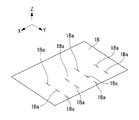
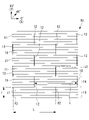
- FIG. 1 It is a perspective view which shows the multi-stack material which concerns on embodiment of this disclosure. It is a perspective view which shows the charge which concerns on embodiment of this disclosure. It is a perspective view which shows an example of the composite material structure which concerns on embodiment of this disclosure. It is a perspective view which shows an example of the composite material structure which concerns on embodiment of this disclosure. It is a schematic exploded perspective view of the charge shown in FIG. It is a schematic perspective view which shows the multi-stack material which formed the continuous cut. It is a schematic perspective view which shows the multi-stack material in which a notch is not formed. It is a schematic perspective view which shows the multi-stack material which made the intermittent notch.
- a charge (laminated structure) 2 is manufactured by laminating a plurality of multi-stack materials (fiber reinforced sheet laminates) 1 in which a plurality of fiber reinforced sheets are laminated, and the charge 2 is applied to the charge (laminated structure) 2.
- the composite material structure 3 having a desired shape is manufactured by subjecting it to bending.
- the composite structure 3 is used, for example, for stringers, spurs, frames, ribs, and the like, which are aircraft parts constituting the aircraft structure.
- the plate thickness direction (stacking direction) of the charge 2 is the Z-axis direction
- one of the directions included in the plane orthogonal to the Z-axis direction is the X-axis direction, and the Z-axis direction and X.
- the direction orthogonal to the axial direction will be described as the Y-axis direction.
- the Z-axis direction may be described as the vertical direction.
- the multi-stack material 1 has a first fiber reinforced sheet 10 and a second fiber reinforced sheet 20 to be laminated.
- the first fiber reinforced sheet 10 and the second fiber reinforced sheet 20 are dry fiber reinforced sheets having no or weak adhesiveness between layers.
- the first fiber reinforced sheet 10 and the second fiber reinforced sheet 20 are integrated by being sewn with a thread formed of glass fiber or the like.
- the first fiber reinforced sheet 10 and the second fiber reinforced sheet 20 each have a plurality of fibers.
- the first fiber reinforced sheet 10 and the second fiber reinforced sheet 20 are different in the direction in which the fibers extend.
- the charge 2 is a stack of a plurality of multi-stack materials 1.
- the charge 2 is flat or has a shape close to flat.
- each multi-stack material 1 is shown in the form of a single sheet. The details of the multi-stack material 1 constituting the charge 2 will be described later.
- the composite structure 3 according to the present embodiment is obtained by bending the charge 2 along the bending line 4.
- the bending line 4A is curved so as to project upward.
- the bending line 4B is curved so as to project downward.
- a method for manufacturing the composite material structure 3 according to the present embodiment will be described.
- a plurality of multi-stack materials 1 are manufactured.
- the second fiber reinforced sheet 20 is laminated on the first fiber reinforced sheet 10.
- the laminated first fiber reinforced sheet 10 and the second fiber reinforced sheet 20 are fixed by sewing with a thread such as glass fiber. In this way, the multi-stack material 1 is manufactured.
- charge 2 is manufactured. As shown in FIGS. 2 and 5, a plurality of manufactured multi-stack materials 1 are laminated to produce a charge 2 having a flat or near-flat shape.
- the multi-stack material 1 (hereinafter referred to as “intermediate layer multi-stack material 1A”) arranged in the intermediate portion in the stacking direction (vertical direction in FIG. 5) is laminated.
- the notch 1Aa formed in the multi-stack material (second fiber reinforced sheet laminate) 1A of the intermediate layer extends from one end in the Y-axis direction along the Y-axis direction (second predetermined direction).
- the plurality of notches 1Aa are arranged side by side at equal intervals (interval B2) along the X-axis direction (second crossing direction).
- the length B1 of the notch 1Aa in the Y-axis direction is the lengths A7 and A8 over the entire region where the compressive force or the tensile force acts when bending the charge 2 (see FIGS. 3 and 4). Longer than.
- the region on which the compressive force or the tensile force acts is, as shown by the arrow A7 in FIG. 3 and the arrow A8 in FIG. 4, when the charge 2 is bent in order to manufacture the composite structure 3. This is the area to be deformed.
- the region deformed during bending means a region that is not fixed during bending. In the examples of FIGS. 3 and 4, when bending is performed, the first portion 2a, which is a portion on one end side in the Y-axis direction, is fixed.
- the region deformed when bending is performed is a region corresponding to the deformed portion 2b and the second portion 2c.
- the notch 1Aa cuts fibers that extend mainly along the X-axis direction.
- the multi-stack material 1 (hereinafter referred to as “the outermost multi-stack material 1B”) arranged at the end in the most laminated direction (vertical direction in FIG. 5) has fibers spread along the 0 degree direction. Determine if you have an existing fiber reinforced sheet.
- the 0 degree direction is along the direction in which the compressive force acts when bending the charge 2 (see arrow A3 in FIG. 3) or the direction in which the tensile force acts (see arrow A6 in FIG. 4).
- the multi-stack material (first fiber reinforced sheet laminate) 1B of the outermost layer does not have a fiber reinforced sheet in which fibers extend along the 0 degree direction (X-axis direction), as shown in FIG. In addition, no cut is formed in the multi-stack material 1.
- the outermost multi-stack material 1B has a fiber-reinforced sheet in which fibers extend along the 0-degree direction (X-axis direction)
- the multi-stack material 1 is as shown in FIG.
- a plurality of notches 1Ba penetrating in the stacking direction are formed. Each notch 1Ba extends in the X-axis direction.
- the plurality of notches 1Ba are formed so as to be arranged in a staggered manner. Specifically, the plurality of notches 1Ba are arranged side by side at equal intervals in the Y-axis direction (first predetermined direction) and the X-axis direction (first crossing direction). The notch 1Ba mainly cuts fibers extending along the X-axis direction.
- the charge 2 is then bent. At this time, as shown in FIGS. 3 and 4, bending is performed so that the bending line 4 is curved.
- the peripheral length A1 of the portion far from the bending line 4A is shorter than the peripheral length A2 of the portion close to the bending line 4A.
- the compressive force acts in the direction indicated by the arrow A3 in the portion where the peripheral length is short.
- the compressive force acts in the direction along the bending line 4A.
- the direction in which the compressive force acts is the 0 degree direction (X-axis direction) in the multi-stack material 1.
- the peripheral length A4 of the portion far from the bending line 4B is longer than the peripheral length A5 of the portion close to the bending line 4B.
- a tensile force acts in the direction indicated by the arrow A6 in the portion having a long circumference.
- the tensile force acts in the direction along the bending line 4B.
- the direction in which the tensile force acts is the 0 degree direction (X-axis direction) in the multi-stack material 1.
- the cut 1Aa may be formed only in the multi-stack material 1A of a part of the intermediate layer.
- a notch 1Aa is formed in the multi-stack material 1A of the intermediate layer including the fiber reinforced sheet in which the fibers extend in the 0 degree direction (X-axis direction), and the fibers extend in the 0 degree direction (X-axis direction).
- the cut may not be formed in the multi-stack material 1A of the intermediate layer that does not include the fiber reinforced sheet.
- the formability of Charge 2 can be improved. Can be improved. Therefore, the occurrence of wrinkles can be suppressed. Further, since the cut 1Aa is formed only in the multi-stack material 1A of a part of the intermediate layers, the charge 2 is manufactured as compared with the case where the cut 1Aa is formed in the multi-stack material 1A of all the intermediate layers. The process can be simplified.
- the multi-stack material 1B of the outermost layer has a fiber reinforced sheet in which fibers extend in a direction along a direction in which a compressive force or a tensile force acts when bending a charge 2 is performed.
- the fibers of the fiber reinforced sheet can be cut. Therefore, the formability of the multi-stack material 1B on the outermost layer can be improved.
- the plurality of notches 1Ba formed in the outermost multi-stack material 1B are arranged side by side at predetermined intervals in the X-axis direction and the Y-axis direction. Is forming.
- a plurality of notches 1Ba are formed intermittently in the X-axis direction and the Y-axis direction.
- the fiber-reinforced sheets to be laminated can be made difficult to disperse. Therefore, it is possible to easily maintain the shape of the entire charge 2. Therefore, the charge 2 can be easily conveyed.
- the plurality of cuts 1Aa formed in the multi-stack material 1A of the intermediate layer arranged in the intermediate portion in the stacking direction (Z-axis direction) have a length in the Y-axis direction in the X-axis direction. It is formed so as to be longer than ⁇ times the distance between the cuts 1Aa. That is, a plurality of notches 1Aa are continuously formed in the Y-axis direction.
- the fibers of the fiber reinforced sheet contained in the multi-stack material 1A of the intermediate layer can be more preferably cut. Therefore, the formability of the multi-stack material 1A in the intermediate layer can be improved. Therefore, the formability of the entire charge 2 can be improved.
- the multi-stack material 1B on the outermost surface has a fiber reinforced sheet in which fibers extend in a direction along which a compressive force or a tensile force acts when bending the charge 2. If not, no cut is formed in the multi-stack material 1B on the outermost layer.
- the fiber-reinforced sheet to be laminated can be more preferably hard to disperse. Therefore, it is possible to more preferably maintain the shape of the entire charge 2. Therefore, the charge 2 can be easily conveyed.
- the multi-stack material 1B on the outermost layer has a fiber reinforced sheet in which the fibers extend in the direction in which the compressive force or the tensile force acts when the charge 2 is bent. Therefore, it is possible to maintain a predetermined shapeability without forming a notch.
- a plurality of cuts may be formed as described below.
- the first fiber reinforced sheet 10 has a plurality of first fibers 11 extending in the 0 degree direction (X-axis direction).
- the 0 degree direction is the direction in which the compressive force acts when bending the charge 2 (see arrow A3 in FIG. 5) or the direction in which the tensile force acts (see arrow A6 in FIG. 6). ).
- the line extending in the left-right direction in FIG. 9 illustrates the first fiber 11.
- the first fiber reinforced sheet 10 has a plurality of first cuts 12 for cutting the first fiber 11. Each first notch 12 extends in the 90 degree direction (Y-axis direction).
- the 90-degree direction is an angle with respect to the 0-degree direction, and is a direction forming a 90-degree angle with respect to the 0-degree direction.
- the plurality of first notches 12 are arranged in a staggered pattern. Further, the plurality of first cuts 12 are arranged so that the cut first fibers 11 have the same length. The details of the shape and arrangement of the first notch 12 will be described later.
- the second fiber reinforced sheet 20 has a plurality of second fibers 21 extending in the 45 degree direction.
- the 45-degree direction is a direction in which an angle of 45 degrees is formed with respect to the 0-degree direction (X-axis direction), which is the direction in which the first fiber 11 extends.
- the diagonal lines in FIG. 10 show the second fiber 21.
- the second fiber reinforced sheet 20 has a plurality of second cuts 22 for cutting the second fiber 21. Each second notch 22 extends in the 90 degree direction.
- the plurality of second notches 22 are arranged in a staggered pattern. Further, the plurality of second cuts 22 are arranged so that the cut second fibers 21 have the same length. The details of the shape and arrangement of the second notch 22 will be described later.
- first notch 12 and the second notch 22 The shapes of the first notch 12 and the second notch 22 are the same. Further, the first cut 12 and the second cut 22 are provided with respect to the multi-stack material 1 (multi-stack material 1B on the outermost layer) in which the first fiber reinforced sheet 10 and the second fiber reinforced sheet 20 are laminated. , It is formed by forming a notch so as to penetrate in the stacking direction. Therefore, the first notch 12 and the second notch 22 are arranged so as to overlap each other when the multi-stack material 1 is viewed from the stacking direction. Therefore, in the following, the arrangement of the plurality of first cuts 12 will be described, and the description of the arrangement of the plurality of second cuts 22 will be omitted.
- each first notch 12 has a length of 90 degrees (Y-axis direction).
- the first notch 12 is formed in a plurality of stages in the 90 degree direction (Y-axis direction).
- the first stage 13 and the second stage 14 are formed so as to be continuous along the 90-degree direction (Y-axis direction).
- the first notch 12 formed in the first stage 13 is arranged apart from each other in the 0 degree direction (X-axis direction), which is a direction intersecting the 90 degree direction (Y-axis direction). Further, the first notches 12 formed in the first stage 13 are arranged side by side at equal intervals (interval L described later) in the 0 degree direction (X-axis direction). The first notch 12 formed in the second stage 14 is also arranged apart in the 0 degree direction (X-axis direction). Further, the first notches 12 formed in the second stage 14 are arranged side by side at equal intervals (interval L described later) in the 0 degree direction (X-axis direction).
- the first notch 12 formed in the second stage 14 is arranged at the midpoint in the 0 degree direction (X-axis direction) between the first notches 12 formed in the adjacent first stage 13. ing. Further, one end of the first notch 12 of the first stage 13 in the 90 degree direction (Y-axis direction) and the other end of the first notch 12 of the second stage 14 in the 90 degree direction are in the 90 degree direction (Y). It is the same position in the axial direction). That is, the first notch 12 of the first stage 13 and the first notch 12 of the second stage 14 are arranged so as not to overlap or separate when viewed from the 0 degree direction (X-axis direction). ..
- the plurality of first cuts 12 and the plurality of second cuts 22 are arranged so as to satisfy the following formula (1).
- n is an arbitrary natural number.
- ⁇ is the angle formed by the direction in which the first fiber 11 extends (0 degree direction (X-axis direction) in this modification) and the direction in which the second fiber 21 extends (45 degree direction in this modification).
- l is the length of the first notch 12 in the 90 degree direction (Y-axis direction).
- L is the distance between the first notches 12 adjacent to each other in the 0 degree direction (X-axis direction).
- the first notch 12 and the second notch 22 are made by making a notch in the laminating direction with respect to the first fiber reinforced sheet 10 and the second fiber reinforced sheet 20 in the laminated state. It is formed at once. Therefore, the first cut 12 and the second cut 22 can be easily formed as compared with the case where the first cut 12 and the second cut 22 are formed separately.
- the other end of the inclusion 22 in the 90-degree direction (Y-axis direction) is set to the same position in the 90-degree direction (Y-axis direction).
- the arrangement of the plurality of first cuts 12 and the plurality of second cuts 22 is defined by the above equation (1).
- first notch 12 and the second notch 22 in the 90 degree direction (Y-axis direction) of the first stage 13 and the first notch 12 and the second notch 22 of the second stage 14 The other end in the 90-degree direction (Y-axis direction) is the same position in the 90-degree direction (Y-axis direction).
- Y-axis direction the 90 degree direction
- both the length of the first fiber 11 of the first stage 13 and the length of the first fiber 11 of the second stage 14 become L. That is, in the first fiber reinforced sheet 10, the lengths of all the first fibers 11 are equal.
- the arrangement of the plurality of first cuts 12 and the plurality of second cuts 22 is defined by the above equation (1).
- S1 is ⁇ 2 (L).
- S2 of the second fiber 21 extending between the other second notches 22 is also ⁇ 2 (L).
- the second fiber reinforced sheet 20 has the same length of all the second fibers 21.
- the lengths of the cut first fiber 11 and the second fiber 21 can be made equal in the first fiber reinforced sheet 10 and the second fiber reinforced sheet 20, respectively. Therefore, the lengths of the first fiber 11 and the second fiber 21 can be made uniform. Further, since the cut first fiber 11 and the second fiber 21 do not have an extreme length, the length of the first fiber 11 and the second fiber 21 can be set to a predetermined length. Therefore, in any of the first fiber reinforced sheet 10 and the second fiber reinforced sheet 20, the strength and shapeability can be made uniform over the entire area, and the predetermined strength and shapeability can be ensured. .. Therefore, it is possible to suppress a decrease in the strength of the multi-stack material 1. In addition, the formability of the multi-stack material 1 can be improved.
- the fiber reinforced sheet when the fiber reinforced sheet is bent, a compressive force or a tensile force may act on the fiber reinforced sheet (see FIGS. 5 and 6).
- the fibers contained in the fiber reinforced sheet do not easily expand and contract in the extending direction of the fibers. Therefore, when the fibers extend along the direction in which the compressive force or the tensile force acts, the fibers cannot absorb the compressive force or the tensile force, and wrinkles are generated on the fiber reinforced sheet.
- the strength of the fiber reinforced sheet may decrease.
- the charge 2 is bent in the 0 degree direction (X-axis direction) in which the first fiber 11 extends and in the 45 degree direction in which the second fiber 21 extends.
- the direction is along the direction in which the compressive force or the tensile force acts on the first fiber reinforced sheet 10 and the second fiber reinforced sheet 20. Therefore, it is possible to cut the fiber extending in the direction in which the compressive force or the tensile force acts. Therefore, the shapeability of the first fiber reinforced sheet 10 and the second fiber reinforced sheet 20 can be improved. Therefore, the occurrence of wrinkles can be suppressed.
- the direction along the direction in which the compressive force or the tensile force acts is a direction other than the direction orthogonal to the direction in which the compressive force or the tensile force acts (in this modification, the 90-degree direction (Y-axis direction)). May be good.
- the present disclosure is not limited to each of the above embodiments, and can be appropriately modified without departing from the gist thereof.
- a dry fiber reinforced sheet is used as the fiber reinforced sheet
- the present disclosure is not limited to this.
- a fiber reinforced sheet in which a resin is impregnated with fibers for example, prepreg
- the laminated structure and the method for manufacturing the laminated structure described in each embodiment are grasped as follows, for example.
- the laminated structure according to one aspect of the present disclosure is a laminated structure (2) in which a plurality of fiber-reinforced sheet laminated bodies (1) in which a plurality of fiber-reinforced sheets (10, 20) are laminated are laminated.
- a two-fiber reinforced sheet laminate (1A) is provided, and the first fiber reinforced sheet laminate is in a direction along a direction in which a compressive force or a tensile force acts when bending a laminated structure.
- the fiber-reinforced sheet having the fiber extending in the (X-axis direction) is formed, and a plurality of cuts (1Ba) penetrating the stacking direction and extending in the first predetermined direction (Y-axis direction) are formed.
- the plurality of cuts formed in the first fiber reinforced sheet laminate are at predetermined intervals in the first crossing direction (X-axis direction) which is the direction intersecting the first predetermined direction and the first predetermined direction.
- the second fiber reinforced sheet laminated body is arranged side by side, and the second fiber reinforced sheet laminate is formed with a notch (1Aa) penetrating in the laminated direction and extending in a second predetermined direction (Y-axis direction), and the second fiber reinforced sheet is reinforced.
- the notch formed in the sheet laminate is an abbreviation for a region in which the length of the notch in the second predetermined direction acts as a compressive force or a tensile force when bending the laminated body structure. It is said to have a length that covers the entire area.
- a notch penetrating in the stacking direction is formed in the first fiber reinforced sheet laminated body arranged at the end in the stacking direction.
- all the fibers contained in the first fiber reinforced sheet laminated body extending in the direction in which the compressive force or the tensile force acts can be cut. Therefore, it is possible to improve the shapeability of the first fiber reinforced sheet laminate.
- the plurality of cuts formed in the first fiber reinforced sheet laminate are arranged side by side at predetermined intervals in the first predetermined direction and the first crossing direction. That is, a plurality of cuts are formed intermittently in the first predetermined direction and the first crossing direction.
- the notch formed in the second fiber reinforced sheet laminated body arranged in the intermediate portion in the laminating direction is used when bending the laminated body structure having a length in the second predetermined direction.
- the length is set to cover substantially the entire region where the compressive force or the tensile force acts. That is, the cuts are continuously formed in the second predetermined direction.
- the fibers of the fiber-reinforced sheet contained in the second fiber-reinforced sheet laminate can be more preferably cut. Therefore, it is possible to improve the shapeability of the second fiber reinforced sheet laminate. Therefore, the shapeability of the entire laminated structure can be improved.
- the plurality of cuts formed in the first fiber reinforced sheet laminated body are formed in a plurality of stages in the first predetermined direction.
- the notch formed in the first stage (13) in the first predetermined direction is arranged so as to be separated from the first predetermined direction in the first crossing direction, and the second stage in the first predetermined direction.
- the notch formed in (14) is arranged at a midpoint in the first crossing direction between the notches formed in the first stage.
- the first fiber reinforced sheet laminated body in the first fiber reinforced sheet laminated body, a plurality of cuts can be appropriately separated from each other in the first predetermined direction and the first crossing direction. Therefore, the shapeability of the first fiber reinforced sheet laminate can be suitably improved. Further, in the first fiber reinforced sheet laminated body, it is possible to make it difficult for the fiber reinforced sheets to be suitably laminated to be separated. Therefore, it is possible to easily maintain the shape of the entire laminated structure. Therefore, the laminated structure can be easily transported.
- the method for manufacturing a laminated structure is a laminated structure (2) in which a plurality of fiber-reinforced sheet laminated bodies (1) in which a plurality of fiber-reinforced sheets (10, 20) are laminated are laminated. ),
- the first fiber reinforced sheet laminate (1B) which is the fiber reinforced sheet laminate arranged at the end in the lamination direction, bends the laminate structure.
- the fiber-reinforced sheet has the fiber extending in a direction (X-axis direction) along the direction in which the compressive force or the tensile force acts, the first fiber-reinforced sheet laminate penetrates the first fiber-reinforced sheet laminate in the laminated direction.
- the first fiber reinforced sheet laminated body cutting step of forming a plurality of cuts (1Ba) extending in a predetermined direction (Y-axis direction) and the fiber reinforced sheet laminated body arranged in an intermediate portion in the laminated direction.
- a second fiber reinforced sheet laminate (1A) that penetrates the laminated direction and forms a notch (1Aa) extending in a second predetermined direction (Y-axis direction) with respect to the second fiber reinforced sheet laminate (1A).
- the first fiber reinforced sheet laminated body cutting step includes a cutting step, and the first fiber reinforced sheet laminated body cutting step is predetermined in a first crossing direction (X-axis direction) which is a direction intersecting the first predetermined direction and the first predetermined direction.
- a plurality of the cuts are formed so as to be arranged side by side at intervals, and in the second fiber reinforced sheet laminated body cutting step, the length of the cuts in the second predetermined direction is the length of the laminated body structure.
- the cut is formed so as to have a length over substantially the entire region where a compressive force or a tensile force acts when bending is applied to the body.
- the direction in which the compressive force or the tensile force acts when the first fiber reinforced sheet laminate, which is the fiber reinforced sheet laminate arranged at the end in the laminate direction bends the laminated structure.
- the fiber-reinforced sheet has the fiber extending in the direction along the above, the fiber of the fiber-reinforced sheet can be cut. Therefore, it is possible to improve the shapeability of the first fiber reinforced sheet laminate.
- a plurality of cuts are made so that the plurality of cuts formed in the first fiber reinforced sheet laminate are arranged side by side at predetermined intervals in the first predetermined direction and the first crossing direction. Is forming. That is, a plurality of cuts are formed intermittently in the first predetermined direction and the first crossing direction.
- the notch formed in the second fiber reinforced sheet laminated body arranged in the intermediate portion in the laminating direction is used when bending the laminated body structure having a length in the second predetermined direction. It is formed so as to have a length over substantially the entire region where a compressive force or a tensile force acts. That is, the cuts are continuously formed in the second predetermined direction.
- the fibers of the fiber-reinforced sheet contained in the second fiber-reinforced sheet laminate can be more preferably cut. Therefore, it is possible to improve the shapeability of the second fiber reinforced sheet laminate. Therefore, the shapeability of the entire laminated structure can be improved.
- a plurality of the cuts are formed in a plurality of stages in the first predetermined direction.
- the notch formed in the first stage (13) in the first predetermined direction is arranged apart from the first crossing direction, and is formed in the second stage (14) in the first predetermined direction.
- the notch is arranged at the midpoint in the first crossing direction between the notches formed in the first stage.
- the first fiber reinforced sheet laminated body in the first fiber reinforced sheet laminated body, a plurality of cuts can be appropriately separated from each other in the first predetermined direction and the first crossing direction. Therefore, the shapeability of the first fiber reinforced sheet laminate can be suitably improved. Further, in the first fiber reinforced sheet laminated body, it is possible to make it difficult for the fiber reinforced sheets to be suitably laminated to be separated. Therefore, it is possible to easily maintain the shape of the entire laminated structure. Therefore, the laminated structure can be easily transported.
- fibers extend in a direction along a direction in which a compressive force or a tensile force acts when bending the laminated structure.
- the step of not forming a cut in the first fiber-reinforced sheet laminate is provided.
- the first fiber reinforced sheet laminate has a fiber reinforced sheet in which fibers extend in a direction along a direction in which a compressive force or a tensile force acts when bending a laminated structure. If not, no cuts are formed in the first fiber reinforced sheet laminate.
- the fiber reinforced sheet to be laminated is more preferably hard to disperse. Can be done. Therefore, it is possible to more preferably maintain the shape of the entire laminated structure. Therefore, the laminated structure can be easily transported.
- the fiber-reinforced sheet in which the fibers extend in the direction in which the compressive force or the tensile force acts when the first fiber-reinforced sheet laminate is bent to the laminated structure structure. Since it does not have, it is possible to maintain a predetermined shapeability without forming a notch.
- Multi-stack material (fiber reinforced sheet laminate) 1A: Multi-stack material (second fiber reinforced sheet laminate) 1Aa: Notch 1B: Multi-stack material (first fiber reinforced sheet laminate) 1Ba: Notch 2: Charge (laminated structure) 3: Composite structure 3A: Composite structure 3B: Composite structure 4: Bending line 4A: Bending line 4B: Bending line 10: First fiber reinforced sheet 11: First fiber 12: First notch 13: 1st stage 14: 2nd stage 20: 2nd fiber reinforced sheet 21: 2nd fiber 22: 2nd notch
Landscapes
- Engineering & Computer Science (AREA)
- Mechanical Engineering (AREA)
- Chemical & Material Sciences (AREA)
- Composite Materials (AREA)
- Textile Engineering (AREA)
- Laminated Bodies (AREA)
- Moulding By Coating Moulds (AREA)
- Casting Or Compression Moulding Of Plastics Or The Like (AREA)
Priority Applications (3)
| Application Number | Priority Date | Filing Date | Title |
|---|---|---|---|
| US18/015,233 US20230302767A1 (en) | 2020-12-28 | 2020-12-28 | Layered body structure and method for manufacturing layered body structure |
| PCT/JP2020/049185 WO2022144998A1 (ja) | 2020-12-28 | 2020-12-28 | 積層体構造体及び積層体構造体の製造方法 |
| JP2022572842A JP7543441B2 (ja) | 2020-12-28 | 2020-12-28 | 積層体構造体及び積層体構造体の製造方法 |
Applications Claiming Priority (1)
| Application Number | Priority Date | Filing Date | Title |
|---|---|---|---|
| PCT/JP2020/049185 WO2022144998A1 (ja) | 2020-12-28 | 2020-12-28 | 積層体構造体及び積層体構造体の製造方法 |
Publications (1)
| Publication Number | Publication Date |
|---|---|
| WO2022144998A1 true WO2022144998A1 (ja) | 2022-07-07 |
Family
ID=82259143
Family Applications (1)
| Application Number | Title | Priority Date | Filing Date |
|---|---|---|---|
| PCT/JP2020/049185 Ceased WO2022144998A1 (ja) | 2020-12-28 | 2020-12-28 | 積層体構造体及び積層体構造体の製造方法 |
Country Status (3)
| Country | Link |
|---|---|
| US (1) | US20230302767A1 (https=) |
| JP (1) | JP7543441B2 (https=) |
| WO (1) | WO2022144998A1 (https=) |
Families Citing this family (1)
| Publication number | Priority date | Publication date | Assignee | Title |
|---|---|---|---|---|
| US12479186B2 (en) * | 2020-12-28 | 2025-11-25 | Mitsubishi Heavy Industries, Ltd. | Fiber-reinforced sheet laminate, production method for fiber-reinforced sheet laminate, and production method for structure |
Citations (6)
| Publication number | Priority date | Publication date | Assignee | Title |
|---|---|---|---|---|
| JPH02115236A (ja) * | 1988-10-25 | 1990-04-27 | Sumitomo Chem Co Ltd | 成形用繊維強化樹脂シートおよびその製造方法並びに繊維強化樹脂成形体の製造方法 |
| JP2008273176A (ja) * | 2007-04-03 | 2008-11-13 | Toray Ind Inc | 繊維強化プラスチックの製造方法 |
| JP2009019201A (ja) * | 2007-06-12 | 2009-01-29 | Toray Ind Inc | 成形材料、プリフォームおよび繊維強化樹脂 |
| JP2015163660A (ja) * | 2014-02-28 | 2015-09-10 | 学校法人大同学園 | プリプレグの製造方法、プリプレグ、繊維強化熱可塑性樹脂の板材および繊維強化熱可塑性樹脂部材 |
| JP2016180037A (ja) * | 2015-03-24 | 2016-10-13 | 三菱レイヨン株式会社 | 炭素繊維強化熱可塑性樹脂複合材料、及びそれを用いた成型体 |
| US20200180260A1 (en) * | 2015-04-13 | 2020-06-11 | Howard E. Crawford, III | Fiber-reinforced composite material |
-
2020
- 2020-12-28 JP JP2022572842A patent/JP7543441B2/ja active Active
- 2020-12-28 WO PCT/JP2020/049185 patent/WO2022144998A1/ja not_active Ceased
- 2020-12-28 US US18/015,233 patent/US20230302767A1/en active Pending
Patent Citations (6)
| Publication number | Priority date | Publication date | Assignee | Title |
|---|---|---|---|---|
| JPH02115236A (ja) * | 1988-10-25 | 1990-04-27 | Sumitomo Chem Co Ltd | 成形用繊維強化樹脂シートおよびその製造方法並びに繊維強化樹脂成形体の製造方法 |
| JP2008273176A (ja) * | 2007-04-03 | 2008-11-13 | Toray Ind Inc | 繊維強化プラスチックの製造方法 |
| JP2009019201A (ja) * | 2007-06-12 | 2009-01-29 | Toray Ind Inc | 成形材料、プリフォームおよび繊維強化樹脂 |
| JP2015163660A (ja) * | 2014-02-28 | 2015-09-10 | 学校法人大同学園 | プリプレグの製造方法、プリプレグ、繊維強化熱可塑性樹脂の板材および繊維強化熱可塑性樹脂部材 |
| JP2016180037A (ja) * | 2015-03-24 | 2016-10-13 | 三菱レイヨン株式会社 | 炭素繊維強化熱可塑性樹脂複合材料、及びそれを用いた成型体 |
| US20200180260A1 (en) * | 2015-04-13 | 2020-06-11 | Howard E. Crawford, III | Fiber-reinforced composite material |
Also Published As
| Publication number | Publication date |
|---|---|
| JP7543441B2 (ja) | 2024-09-02 |
| JPWO2022144998A1 (https=) | 2022-07-07 |
| US20230302767A1 (en) | 2023-09-28 |
Similar Documents
| Publication | Publication Date | Title |
|---|---|---|
| RU2406604C2 (ru) | Способ формовки конструкционного элемента из композиционного материала и конструкционный элемент из композиционного материала | |
| US6553734B1 (en) | Composite structural panel with undulated body | |
| JP2554063Y2 (ja) | 胴体壁内装板 | |
| US9937685B2 (en) | Industrial products engineered from processed bamboo or vegetable cane | |
| JP6309324B2 (ja) | 複合材構造体、これを備えた航空機翼および航空機胴体、並びに複合材構造体の製造方法 | |
| EP3018293A1 (en) | Composite article with fibre-reinforced sandwich core | |
| US8815368B2 (en) | Composite sheet having a core having end walls and a mat with fibers | |
| RU2011145333A (ru) | Способ изготовления элемента из композитного материала и листовой слоистый материал с предварительной пропиткой | |
| CN110867659A (zh) | 一种透波天线罩 | |
| WO2022145005A1 (ja) | 繊維強化シート積層体並びに繊維強化シート積層体の製造方法及び構造体の製造方法 | |
| WO2022144998A1 (ja) | 積層体構造体及び積層体構造体の製造方法 | |
| JP6238168B2 (ja) | 複合材構造 | |
| JP7412458B2 (ja) | 複合材構造体の製造方法及び積層体の製造方法並びに積層体及び積層型 | |
| CN107923082A (zh) | 纤维结构体和纤维增强复合材料 | |
| CN107709645A (zh) | 纤维层叠体、纤维层叠体的制造方法以及纤维强化复合材料 | |
| CN110678323A (zh) | 复合材料的构造体 | |
| CN102159390A (zh) | 增强的复合夹芯板 | |
| JP7112950B2 (ja) | 複合材の設計方法および複合材 | |
| JP6641489B2 (ja) | 複合材部材、引抜成形装置及び引抜成形方法 | |
| GB2225282A (en) | Fibre reinforced foam structural components | |
| EP3330072A1 (en) | Textile laminate, textile laminate production method, and textile laminate production device | |
| JPWO2022144998A5 (https=) | ||
| US9517614B1 (en) | Delamination and crack prevention layer for structural sandwich panels | |
| JP2021025148A (ja) | 繊維構造体、繊維強化複合材、繊維構造体の製造方法、及び賦形用治具 | |
| JP6900594B2 (ja) | 金属/樹脂繊維テープ材織物及びその製造方法、並びに金属/樹脂繊維テープ材織物積層材 |
Legal Events
| Date | Code | Title | Description |
|---|---|---|---|
| 121 | Ep: the epo has been informed by wipo that ep was designated in this application |
Ref document number: 20968010 Country of ref document: EP Kind code of ref document: A1 |
|
| ENP | Entry into the national phase |
Ref document number: 2022572842 Country of ref document: JP Kind code of ref document: A |
|
| NENP | Non-entry into the national phase |
Ref country code: DE |
|
| 122 | Ep: pct application non-entry in european phase |
Ref document number: 20968010 Country of ref document: EP Kind code of ref document: A1 |