WO2022144959A1 - Appareil de commande de véhicule, système de véhicule, procédé de commande de véhicule et programme - Google Patents
Appareil de commande de véhicule, système de véhicule, procédé de commande de véhicule et programme Download PDFInfo
- Publication number
- WO2022144959A1 WO2022144959A1 PCT/JP2020/049103 JP2020049103W WO2022144959A1 WO 2022144959 A1 WO2022144959 A1 WO 2022144959A1 JP 2020049103 W JP2020049103 W JP 2020049103W WO 2022144959 A1 WO2022144959 A1 WO 2022144959A1
- Authority
- WO
- WIPO (PCT)
- Prior art keywords
- vehicle
- mode
- combination switch
- control device
- driving
- Prior art date
Links
- 238000000034 method Methods 0.000 title claims description 15
- 238000004891 communication Methods 0.000 claims abstract description 110
- 230000005856 abnormality Effects 0.000 claims abstract description 73
- 230000001133 acceleration Effects 0.000 claims abstract description 30
- 230000008859 change Effects 0.000 claims description 32
- 238000012544 monitoring process Methods 0.000 claims description 32
- 238000012545 processing Methods 0.000 description 28
- 230000006870 function Effects 0.000 description 14
- 238000010586 diagram Methods 0.000 description 10
- 230000009471 action Effects 0.000 description 9
- 230000007547 defect Effects 0.000 description 8
- 238000001514 detection method Methods 0.000 description 8
- 230000008569 process Effects 0.000 description 8
- 230000007246 mechanism Effects 0.000 description 6
- 238000002485 combustion reaction Methods 0.000 description 5
- 230000005540 biological transmission Effects 0.000 description 4
- 230000010354 integration Effects 0.000 description 4
- 230000004044 response Effects 0.000 description 4
- 230000001052 transient effect Effects 0.000 description 4
- 241000283070 Equus zebra Species 0.000 description 3
- 238000007499 fusion processing Methods 0.000 description 3
- 238000005070 sampling Methods 0.000 description 3
- 238000013473 artificial intelligence Methods 0.000 description 2
- 230000006866 deterioration Effects 0.000 description 2
- 239000000446 fuel Substances 0.000 description 2
- 230000005484 gravity Effects 0.000 description 2
- 230000001172 regenerating effect Effects 0.000 description 2
- 238000004092 self-diagnosis Methods 0.000 description 2
- 101100184045 Arabidopsis thaliana MICU gene Proteins 0.000 description 1
- HBBGRARXTFLTSG-UHFFFAOYSA-N Lithium ion Chemical compound [Li+] HBBGRARXTFLTSG-UHFFFAOYSA-N 0.000 description 1
- 230000003044 adaptive effect Effects 0.000 description 1
- 238000013459 approach Methods 0.000 description 1
- 230000003542 behavioural effect Effects 0.000 description 1
- 238000005452 bending Methods 0.000 description 1
- 230000001413 cellular effect Effects 0.000 description 1
- 230000000295 complement effect Effects 0.000 description 1
- 230000036461 convulsion Effects 0.000 description 1
- 238000013135 deep learning Methods 0.000 description 1
- 230000003111 delayed effect Effects 0.000 description 1
- 238000005516 engineering process Methods 0.000 description 1
- 230000001771 impaired effect Effects 0.000 description 1
- 229910001416 lithium ion Inorganic materials 0.000 description 1
- 229910044991 metal oxide Inorganic materials 0.000 description 1
- 150000004706 metal oxides Chemical class 0.000 description 1
- 238000012986 modification Methods 0.000 description 1
- 230000004048 modification Effects 0.000 description 1
- 230000002093 peripheral effect Effects 0.000 description 1
- 239000004065 semiconductor Substances 0.000 description 1
- 238000006467 substitution reaction Methods 0.000 description 1
Images


Classifications
-
- B—PERFORMING OPERATIONS; TRANSPORTING
- B60—VEHICLES IN GENERAL
- B60W—CONJOINT CONTROL OF VEHICLE SUB-UNITS OF DIFFERENT TYPE OR DIFFERENT FUNCTION; CONTROL SYSTEMS SPECIALLY ADAPTED FOR HYBRID VEHICLES; ROAD VEHICLE DRIVE CONTROL SYSTEMS FOR PURPOSES NOT RELATED TO THE CONTROL OF A PARTICULAR SUB-UNIT
- B60W60/00—Drive control systems specially adapted for autonomous road vehicles
- B60W60/005—Handover processes
-
- B—PERFORMING OPERATIONS; TRANSPORTING
- B60—VEHICLES IN GENERAL
- B60Q—ARRANGEMENT OF SIGNALLING OR LIGHTING DEVICES, THE MOUNTING OR SUPPORTING THEREOF OR CIRCUITS THEREFOR, FOR VEHICLES IN GENERAL
- B60Q1/00—Arrangement of optical signalling or lighting devices, the mounting or supporting thereof or circuits therefor
- B60Q1/02—Arrangement of optical signalling or lighting devices, the mounting or supporting thereof or circuits therefor the devices being primarily intended to illuminate the way ahead or to illuminate other areas of way or environments
- B60Q1/04—Arrangement of optical signalling or lighting devices, the mounting or supporting thereof or circuits therefor the devices being primarily intended to illuminate the way ahead or to illuminate other areas of way or environments the devices being headlights
- B60Q1/14—Arrangement of optical signalling or lighting devices, the mounting or supporting thereof or circuits therefor the devices being primarily intended to illuminate the way ahead or to illuminate other areas of way or environments the devices being headlights having dimming means
- B60Q1/1446—Arrangement of optical signalling or lighting devices, the mounting or supporting thereof or circuits therefor the devices being primarily intended to illuminate the way ahead or to illuminate other areas of way or environments the devices being headlights having dimming means controlled by mechanically actuated switches
- B60Q1/1453—Hand actuated switches
- B60Q1/1461—Multifunction switches for dimming headlights and controlling additional devices, e.g. for controlling direction indicating lights
- B60Q1/1484—Multifunction switches for dimming headlights and controlling additional devices, e.g. for controlling direction indicating lights mounted on the steering wheel
-
- B—PERFORMING OPERATIONS; TRANSPORTING
- B60—VEHICLES IN GENERAL
- B60W—CONJOINT CONTROL OF VEHICLE SUB-UNITS OF DIFFERENT TYPE OR DIFFERENT FUNCTION; CONTROL SYSTEMS SPECIALLY ADAPTED FOR HYBRID VEHICLES; ROAD VEHICLE DRIVE CONTROL SYSTEMS FOR PURPOSES NOT RELATED TO THE CONTROL OF A PARTICULAR SUB-UNIT
- B60W30/00—Purposes of road vehicle drive control systems not related to the control of a particular sub-unit, e.g. of systems using conjoint control of vehicle sub-units, or advanced driver assistance systems for ensuring comfort, stability and safety or drive control systems for propelling or retarding the vehicle
- B60W30/18—Propelling the vehicle
- B60W30/182—Selecting between different operative modes, e.g. comfort and performance modes
-
- B—PERFORMING OPERATIONS; TRANSPORTING
- B60—VEHICLES IN GENERAL
- B60W—CONJOINT CONTROL OF VEHICLE SUB-UNITS OF DIFFERENT TYPE OR DIFFERENT FUNCTION; CONTROL SYSTEMS SPECIALLY ADAPTED FOR HYBRID VEHICLES; ROAD VEHICLE DRIVE CONTROL SYSTEMS FOR PURPOSES NOT RELATED TO THE CONTROL OF A PARTICULAR SUB-UNIT
- B60W50/00—Details of control systems for road vehicle drive control not related to the control of a particular sub-unit, e.g. process diagnostic or vehicle driver interfaces
- B60W50/02—Ensuring safety in case of control system failures, e.g. by diagnosing, circumventing or fixing failures
- B60W50/0205—Diagnosing or detecting failures; Failure detection models
-
- B—PERFORMING OPERATIONS; TRANSPORTING
- B60—VEHICLES IN GENERAL
- B60W—CONJOINT CONTROL OF VEHICLE SUB-UNITS OF DIFFERENT TYPE OR DIFFERENT FUNCTION; CONTROL SYSTEMS SPECIALLY ADAPTED FOR HYBRID VEHICLES; ROAD VEHICLE DRIVE CONTROL SYSTEMS FOR PURPOSES NOT RELATED TO THE CONTROL OF A PARTICULAR SUB-UNIT
- B60W50/00—Details of control systems for road vehicle drive control not related to the control of a particular sub-unit, e.g. process diagnostic or vehicle driver interfaces
- B60W50/02—Ensuring safety in case of control system failures, e.g. by diagnosing, circumventing or fixing failures
- B60W50/029—Adapting to failures or work around with other constraints, e.g. circumvention by avoiding use of failed parts
-
- B—PERFORMING OPERATIONS; TRANSPORTING
- B60—VEHICLES IN GENERAL
- B60W—CONJOINT CONTROL OF VEHICLE SUB-UNITS OF DIFFERENT TYPE OR DIFFERENT FUNCTION; CONTROL SYSTEMS SPECIALLY ADAPTED FOR HYBRID VEHICLES; ROAD VEHICLE DRIVE CONTROL SYSTEMS FOR PURPOSES NOT RELATED TO THE CONTROL OF A PARTICULAR SUB-UNIT
- B60W60/00—Drive control systems specially adapted for autonomous road vehicles
- B60W60/001—Planning or execution of driving tasks
- B60W60/0015—Planning or execution of driving tasks specially adapted for safety
- B60W60/0018—Planning or execution of driving tasks specially adapted for safety by employing degraded modes, e.g. reducing speed, in response to suboptimal conditions
- B60W60/00186—Planning or execution of driving tasks specially adapted for safety by employing degraded modes, e.g. reducing speed, in response to suboptimal conditions related to the vehicle
-
- B—PERFORMING OPERATIONS; TRANSPORTING
- B60—VEHICLES IN GENERAL
- B60W—CONJOINT CONTROL OF VEHICLE SUB-UNITS OF DIFFERENT TYPE OR DIFFERENT FUNCTION; CONTROL SYSTEMS SPECIALLY ADAPTED FOR HYBRID VEHICLES; ROAD VEHICLE DRIVE CONTROL SYSTEMS FOR PURPOSES NOT RELATED TO THE CONTROL OF A PARTICULAR SUB-UNIT
- B60W60/00—Drive control systems specially adapted for autonomous road vehicles
- B60W60/005—Handover processes
- B60W60/0053—Handover processes from vehicle to occupant
-
- G—PHYSICS
- G08—SIGNALLING
- G08G—TRAFFIC CONTROL SYSTEMS
- G08G1/00—Traffic control systems for road vehicles
- G08G1/09—Arrangements for giving variable traffic instructions
-
- B—PERFORMING OPERATIONS; TRANSPORTING
- B60—VEHICLES IN GENERAL
- B60Q—ARRANGEMENT OF SIGNALLING OR LIGHTING DEVICES, THE MOUNTING OR SUPPORTING THEREOF OR CIRCUITS THEREFOR, FOR VEHICLES IN GENERAL
- B60Q1/00—Arrangement of optical signalling or lighting devices, the mounting or supporting thereof or circuits therefor
- B60Q1/02—Arrangement of optical signalling or lighting devices, the mounting or supporting thereof or circuits therefor the devices being primarily intended to illuminate the way ahead or to illuminate other areas of way or environments
- B60Q1/04—Arrangement of optical signalling or lighting devices, the mounting or supporting thereof or circuits therefor the devices being primarily intended to illuminate the way ahead or to illuminate other areas of way or environments the devices being headlights
- B60Q1/14—Arrangement of optical signalling or lighting devices, the mounting or supporting thereof or circuits therefor the devices being primarily intended to illuminate the way ahead or to illuminate other areas of way or environments the devices being headlights having dimming means
- B60Q1/1446—Arrangement of optical signalling or lighting devices, the mounting or supporting thereof or circuits therefor the devices being primarily intended to illuminate the way ahead or to illuminate other areas of way or environments the devices being headlights having dimming means controlled by mechanically actuated switches
- B60Q1/1453—Hand actuated switches
- B60Q1/1461—Multifunction switches for dimming headlights and controlling additional devices, e.g. for controlling direction indicating lights
- B60Q1/1469—Multifunction switches for dimming headlights and controlling additional devices, e.g. for controlling direction indicating lights controlled by or attached to a single lever, e.g. steering column stalk switches
- B60Q1/1476—Multifunction switches for dimming headlights and controlling additional devices, e.g. for controlling direction indicating lights controlled by or attached to a single lever, e.g. steering column stalk switches comprising switch controlling means located near the free end of the lever, e.g. press buttons, rotatable rings
-
- B—PERFORMING OPERATIONS; TRANSPORTING
- B60—VEHICLES IN GENERAL
- B60Q—ARRANGEMENT OF SIGNALLING OR LIGHTING DEVICES, THE MOUNTING OR SUPPORTING THEREOF OR CIRCUITS THEREFOR, FOR VEHICLES IN GENERAL
- B60Q11/00—Arrangement of monitoring devices for devices provided for in groups B60Q1/00 - B60Q9/00
-
- B—PERFORMING OPERATIONS; TRANSPORTING
- B60—VEHICLES IN GENERAL
- B60W—CONJOINT CONTROL OF VEHICLE SUB-UNITS OF DIFFERENT TYPE OR DIFFERENT FUNCTION; CONTROL SYSTEMS SPECIALLY ADAPTED FOR HYBRID VEHICLES; ROAD VEHICLE DRIVE CONTROL SYSTEMS FOR PURPOSES NOT RELATED TO THE CONTROL OF A PARTICULAR SUB-UNIT
- B60W30/00—Purposes of road vehicle drive control systems not related to the control of a particular sub-unit, e.g. of systems using conjoint control of vehicle sub-units, or advanced driver assistance systems for ensuring comfort, stability and safety or drive control systems for propelling or retarding the vehicle
- B60W30/18—Propelling the vehicle
- B60W30/18009—Propelling the vehicle related to particular drive situations
- B60W30/18163—Lane change; Overtaking manoeuvres
Definitions
- the present invention relates to a vehicle control device, a vehicle system, a vehicle control method, and a program.
- the vehicle could not be controlled properly with the conventional technology.
- the present invention has been made in consideration of such circumstances, and one of the objects of the present invention is to provide a vehicle control device, a vehicle system, a vehicle control method, and a program capable of controlling a vehicle more appropriately. do.
- the vehicle control device has the following configuration. (1):
- the vehicle control device includes a recognition unit that recognizes the surrounding conditions of the vehicle, an operation control unit that controls one or both of steering or acceleration / deceleration of the vehicle, and an operation mode of the vehicle. Is determined to be one of a plurality of operation modes including a first operation mode and a second operation mode, and in the second operation mode, the task imposed on the driver is set to the first operation mode. It is relatively mild and one or both of the steering and acceleration / deceleration of the vehicle are controlled by the operation control unit, and the operation control unit controls the vehicle in the second operation mode.
- the device related to the combination switch connected between the operation control unit and the combination switch via a communication line, or the communication performed by the combination switch and the operation control unit.
- a mode determining unit for changing the operation mode to the first operation mode is provided.
- the second driving mode is a mode in which the driver is not required to perform a task of monitoring the front and a task of gripping the steering wheel
- the first driving mode is This is a mode in which the vehicle is controlled by the driving operation of the driver.
- the combination switch is provided near the steering wheel or the steering wheel of the vehicle, and at least operates the headlight, the direction indicator, and the wiper of the vehicle. Includes switches and.
- the device related to the combination switch controls an instrument connected between the operation control unit and the combination switch via a communication line.
- An instrument device a control device that controls a target device for the operation based on an operation performed on the combination switch connected via a communication line between the operation control unit and the combination switch, or the combination. It includes at least one of the driving units that drives the target device of the operation based on the operation of the switch.
- the mode determining unit indicates that the information including the switch included in the combination switch has failed or that the device related to the combination switch has failed. When the indicated information is continuously acquired for the first hour or longer, it is determined that the abnormality has occurred.
- the mode determination unit is in a state where the voltage input to the operation control unit is equal to or higher than the first voltage for the first hour, and the device related to the combination switch and the operation.
- the communication state with the control unit is normal and no abnormality has occurred in the communication state between the device related to the combination switch and the combination switch, the determination of whether or not the abnormality has occurred is started.
- the vehicle system has a recognition unit that recognizes the surrounding conditions of the vehicle, a driving control unit that controls one or both of steering or acceleration / deceleration of the vehicle, and a driving mode of the vehicle.
- a plurality of operation modes including a first operation mode and a second operation mode are determined, and in the second operation mode, the task imposed on the driver is compared with the first operation mode.
- the operation control unit controls one or both of the steering and acceleration / deceleration of the vehicle, and the operation control unit controls the vehicle in the second operation mode.
- a mode determination unit that changes the operation mode to the first operation mode when an abnormality occurs in the combination switch, the instrument device, the control device, or the communication performed by the combination switch and the operation control unit.
- the instrument device is connected to the vehicle control device via the first communication line, communicates with the vehicle control device based on the first communication protocol, and controls the instrument via the second communication line.
- the control device which is connected to the instrument device, communicates with the instrument device based on the second communication protocol, and controls the target device of the operation based on the operation performed on the combination switch, and the third. It includes a combination switch that is connected to the control device via a communication line, communicates with the control device based on the second communication protocol, and outputs a signal corresponding to the operation of the occupant of the vehicle to the control device.
- a computer mounted on the vehicle recognizes the surrounding conditions of the vehicle and controls one or both of steering or acceleration / deceleration of the vehicle to drive the vehicle.
- the mode is determined to be one of a plurality of operation modes including a first operation mode and a second operation mode, and in the second operation mode, the task imposed on the driver is the first operation mode. It is milder than the above, and one or both of the steering and acceleration / deceleration of the vehicle are controlled without depending on the operation of the driver of the vehicle, and the vehicle is controlled in the second operation mode.
- the device related to the combination switch connected between the computer and the combination switch via a communication line, or the communication performed by the combination switch and the computer.
- the operation mode is changed to the first operation mode.
- the program according to one aspect of the present invention causes a computer mounted on the vehicle to recognize the surrounding conditions of the vehicle, control one or both of steering and acceleration / deceleration of the vehicle, and set the operation mode of the vehicle.
- a plurality of operation modes including a first operation mode and a second operation mode are determined, and in the second operation mode, the task imposed on the driver is compared with the first operation mode.
- the vehicle is mild and one or both of the steering and acceleration / deceleration of the vehicle are controlled without depending on the operation of the driver of the vehicle, and the vehicle is controlled in the second operation mode.
- the device related to the combination switch connected between the computer and the combination switch via a communication line, or the communication performed by the combination switch and the computer the operation is performed.
- the mode is changed to the first operation mode.
- the driving mode is changed to the first driving mode, so that the vehicle can be controlled more appropriately.
- FIG. 1 is a configuration diagram of a vehicle system 1 using the vehicle control device according to the embodiment.
- the vehicle on which the vehicle system 1 is mounted is, for example, a vehicle such as a two-wheeled vehicle, a three-wheeled vehicle, or a four-wheeled vehicle, and the drive source thereof is an internal combustion engine such as a diesel engine or a gasoline engine, an electric motor, or a combination thereof.
- the electric motor operates by using the electric power generated by the generator connected to the internal combustion engine or the electric power generated by the secondary battery or the fuel cell.
- the vehicle will be described as a hybrid vehicle driven by a four-wheel internal combustion engine and an electric motor.
- the vehicle system 1 has multiplex or redundant functions for controlling the vehicle in the first group and the second group, which will be described later. This improves the reliability of the vehicle system 1.
- the vehicle system 1 includes, for example, a camera 10, a LIDAR (Light Detection and Ringing) 14, a first recognition device 16, a communication device 20, an HMI (Human Machine Interface) 30, a vehicle sensor 40, and a navigation device 50.
- MPU Map Positioning Unit
- driver monitor camera 70 operation controller 80
- combination switch 90 multifunction integrated control unit (MICU; Multiplex Integrated Control Unit) 92
- instrument device 94 instrument device 94
- HUD Head Up Display
- the vehicle system 1 includes, for example, a camera 310, a radar device 312, and a second control device 320.
- the configurations shown in FIGS. 1, 3 and 5, which will be described later, are merely examples, and a part of the configuration may be omitted or another configuration may be added.
- the connection mode of the communication lines shown in FIG. 1, FIGS. 3 and 5, which will be described later, is merely an example, and the connection mode may be changed as appropriate.
- each functional configuration may be integrated or distributed.
- the vehicle system 1 is classified into a functional configuration included in the first group and a functional configuration included in the second group. Details of the first group and the second group will be described later (see FIG. 5).
- the vehicle system 1 includes, for example, a sonar that detects an object at a short distance, a multi-view camera that captures an image of the surroundings of the vehicle, and the like, but these are not shown.
- the camera 10 is a digital camera that uses a solid-state image sensor such as a CCD (Charge Coupled Device) or a CMOS (Complementary Metal Oxide Semiconductor).
- the camera 10 is attached to an arbitrary position on the vehicle (hereinafter referred to as vehicle M) on which the vehicle system 1 is mounted.
- vehicle M vehicle
- the camera 10 is attached to the upper part of the front windshield, the back surface of the rear-view mirror, and the like.
- the camera 10 periodically and repeatedly images the periphery of the vehicle M, for example.
- the camera 10 may be a stereo camera.
- the LIDAR14 irradiates the periphery of the vehicle M with light (or an electromagnetic wave having a wavelength close to that of light) and measures scattered light.
- the LIDAR 14 detects the distance to the object based on the time from light emission to light reception.
- the emitted light is, for example, a pulsed laser beam.
- the LIDAR 14 is attached to any part of the vehicle M.
- the first recognition device 16 performs sensor fusion processing on the detection result by a part or all of the camera 10 and the LIDAR 14, recognizes the position, type, speed, etc. of the object, and recognizes the recognition result as the first control device. Output to 100.
- the first recognition device 16 may output the detection results of the camera 10 and the LIDAR 14 to the first control device 100 as they are.
- the first recognition device 16 may be omitted from the vehicle system 1.
- the first recognition device 16 may further perform a sensor fusion process using the detection result of the radar device 312.
- the communication device 20 communicates with other vehicles existing in the vicinity of the vehicle M by using, for example, a cellular network, a Wi-Fi network, Bluetooth (registered trademark), DSRC (Dedicated Short Range Communication), or a wireless base. Communicate with various server devices via the station.
- a cellular network for example, a Wi-Fi network, Bluetooth (registered trademark), DSRC (Dedicated Short Range Communication), or a wireless base.
- Bluetooth registered trademark
- DSRC Dedicated Short Range Communication
- the HMI 30 presents various information to the occupant of the vehicle M and accepts input operations by the occupant.
- the HMI 30 includes various display devices, speakers, buzzers, touch panels, switches, keys and the like.
- the HMI 30 may include a predetermined output unit provided on the steering wheel and prompting the occupant to grip the steering wheel, and a HUD.
- the vehicle sensor 40 is used for controlling the vehicle M such as a vehicle speed sensor that detects the speed of the vehicle M, an acceleration sensor that detects acceleration, a yaw rate sensor that detects an angular speed around the vertical axis, and an orientation sensor that detects the direction of the vehicle M. Includes various sensors.
- the navigation device 50 includes, for example, a GNSS (Global Navigation Satellite System) receiver 51, a navigation HMI 52, and a route determination unit 53.
- the navigation device 50 holds the first map information 54 in a storage device such as an HDD (Hard Disk Drive) or a flash memory.
- the GNSS receiver 51 identifies the position of the vehicle M based on the signal received from the GNSS satellite.
- the position of the vehicle M may be specified or complemented by an INS (Inertial Navigation System) using the output of the vehicle sensor 40.
- the navigation HMI 52 includes a display device, a speaker, a touch panel, keys, and the like.
- the navigation HMI 52 may be partially or wholly shared with the above-mentioned HMI 30.
- the route determination unit 53 is, for example, a route from the position of the vehicle M specified by the GNSS receiver 51 (or an arbitrary position input) to the destination input by the occupant using the navigation HMI 52 (hereinafter, a map).
- the upper route) is determined with reference to the first map information 54.
- the first map information 54 is, for example, information in which a road shape is expressed by a link indicating a road and a node connected by the link.
- the first map information 54 may include road curvature, POI (Point Of Interest) information, and the like.
- the route on the map is output to MPU60.
- the navigation device 50 may provide route guidance using the navigation HMI 52 based on the route on the map.
- the navigation device 50 may be realized by, for example, the function of a terminal device such as a smartphone or a tablet terminal owned by an occupant.
- the navigation device 50 may transmit the current position and the destination to the navigation server via the communication device 20 and acquire a route equivalent to the route on the map from the navigation server.
- the MPU 60 includes, for example, a recommended lane determination unit 61, and holds the second map information 62 in a storage device such as an HDD or a flash memory.
- the recommended lane determination unit 61 divides the route on the map provided by the navigation device 50 into a plurality of blocks (for example, divides the route into 100 [m] units with respect to the vehicle traveling direction), and refers to the second map information 62. Determine the recommended lane for each block.
- the recommended lane determination unit 61 determines which lane to drive from the left. When a branch point exists on the route on the map, the recommended lane determination unit 61 determines the recommended lane so that the vehicle M can travel on a reasonable route to proceed to the branch destination. Further, the MPU 60 recognizes the position of the vehicle M based on the detection result of the gyro sensor (not shown), the position of the vehicle M specified by the GNSS receiver 51, and the like.
- the second map information 62 is map information with higher accuracy than the first map information 54.
- the second map information 62 includes, for example, information on the center of the lane, information on the boundary of the lane, and the like. Further, the second map information 62 may include road information, traffic regulation information, address information (address / zip code), facility information, telephone number information, and the like.
- the second map information 62 may be updated at any time by the communication device 20 communicating with another device.
- the second map information 62 stores information indicating the position and range of the zebra zone (guide zone).
- the zebra zone is a road marking for guiding the traveling of the vehicle M.
- the zebra zone is, for example, a sign represented by a striped pattern.
- the driver monitor camera 70 is, for example, a digital camera that uses a solid-state image sensor such as a CCD or CMOS.
- the driver monitor camera 70 is located at an arbitrary position on the vehicle M at a position and orientation in which the head of an occupant (hereinafter referred to as a driver) seated in the driver's seat of the vehicle M can be imaged from the front (in the direction in which the face is imaged). It is attached.
- the driver monitor camera 70 is attached to the upper part of the display device provided in the central portion of the instrument panel of the vehicle M.
- the driving controller 80 includes, for example, an accelerator pedal, a brake pedal, a shift lever, and other controls in addition to the steering wheel 82.
- a sensor for detecting the amount of operation or the presence or absence of operation is attached to the operation controller 80, and the detection result is the first control device 100, the second control device 320, the traveling driving force output device 200, or the brake. It is output to a part or all of the device 210 and the steering device 220.
- a steering grip sensor 84 is attached to the steering wheel 82.
- the steering grip sensor 84 is realized by a capacitance sensor or the like, and has a signal capable of detecting whether or not the driver is gripping the steering wheel 82 (meaning that the steering wheel 82 is in contact with the steering wheel 82). 1 Output to the control device 100 or the second control device 320.
- the combination switch 90 is provided, for example, in the steering wheel or in the vicinity of the steering wheel (for example, the steering column).
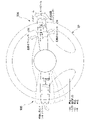
- FIG. 2 is a diagram showing an example of the combination switch 90.
- the combination switch 90 includes, for example, a first operating lever 90A and a second operating lever 90B.
- the first operation lever 90A is, for example, a lever for adjusting the lighting state of lights (for example, headlights, vehicle side lights, fog lamps).
- the lighting state of the light is controlled by the auto mode or the manual mode.
- the auto mode is a mode in which the vehicle M automatically controls the lighting state of the light based on the illuminance detected by the illuminance sensor.
- the manual mode is a mode in which the lighting state of the light is controlled based on the operation performed by the occupant on the first operation lever 90A.
- the first operation lever 90A further functions as a lever for operating the lighting state of the turn signal.
- the first operation lever 90A is operated to light the turn signal (for example, when the operation for changing lanes to the right is performed to overtake)
- the information corresponding to the operation is stored in the multifunction integrated control device 92.
- the first control device 100 performs an auto lane change according to, for example, the transmitted information.
- the second operation lever 90B is, for example, a lever for adjusting the operating state of the wiper.
- the operating state of the wiper is controlled by the auto mode or the manual mode.
- the auto mode is a mode in which the vehicle M automatically controls the operating state of the wiper based on the amount of rainfall detected by the rain sensor.
- the manual mode is a mode in which the operating state of the wiper is controlled based on the operation performed by the occupant on the second operation lever 90B.
- the multifunctional integrated control device 92 controls turn signals, lights, wipers, power windows, door locks, and the like.
- the multifunctional integrated control device 92 controls, for example, the lighting state of the light and the lighting state of the turn signal according to the operation performed on the first operation lever 90A.
- the multifunctional integrated control device 92 controls the operating state of the wiper by driving a drive unit that transmits power to the wiper in response to an operation performed on the second operation lever 90B, for example.
- the instrument device 94 includes a meter panel and a control unit that controls the meter panel.
- the meter panel is provided on the instrument panel in front of the driver's seat, and provides information such as the speed of the vehicle M, the operating state of the drive source, and the remaining fuel to the occupants.
- the control unit of the instrument device 94 controls the instrument panel based on information acquired from various sensors and other control units provided on the vehicle M.
- the HUD96 projects an image onto a part of the front windshield in front of the driver's seat so that the eyes of the occupant seated in the driver's seat can see the virtual image.
- the HUD 96 makes the occupant visually recognize information for assisting driving, for example.
- the information for assisting driving is, for example, the vehicle speed or the direction of the destination.
- the HUD 96 is controlled by a control device (not shown) or a first control device 100.
- the first control device 100 includes, for example, a first control unit 120, a second control unit 160, and a first monitoring unit 170.
- the first control unit 120, the second control unit 160, and the first monitoring unit 170 are realized by, for example, a hardware processor such as a CPU (Central Processing Unit) executing a program (software).
- a hardware processor such as a CPU (Central Processing Unit) executing a program (software).
- Some or all of these components are hardware (circuit parts) such as LSI (Large Scale Integration), ASIC (Application Specific Integrated Circuit), FPGA (Field-Programmable Gate Array), and GPU (Graphics Processing Unit). It may be realized by (including circuits), or it may be realized by the cooperation of software and hardware.
- the program may be stored in advance in a device (a storage device including a non-transient storage medium) such as an HDD or a flash memory of the first control device 100, or a detachable storage such as a DVD or a CD-ROM. It is stored in a medium, and may be installed in the HDD or flash memory of the first control device 100 by mounting the storage medium (non-transient storage medium) in the drive device.
- FIG. 3 is a functional configuration diagram of the first control unit 120 and the second control unit 160.
- the first control unit 120 includes, for example, a recognition unit 130, an action plan generation unit 140, and a mode determination unit 150.
- the first control unit 120 realizes a function by AI (Artificial Intelligence) and a function by a model given in advance in parallel. For example, the function of "recognizing an intersection” is executed in parallel with the recognition of an intersection by deep learning or the like and the recognition based on predetermined conditions (there are signals that can be matched with patterns, road markings, etc.). It may be realized by scoring and comprehensively evaluating. This ensures the reliability of automated driving.
- AI Artificial Intelligence
- the recognition unit 130 recognizes the position, speed, acceleration, and other states of objects around the vehicle M based on the information input from the camera 10 and the LIDAR 14 via the first recognition device 16.
- the position of the object is recognized as, for example, a position on absolute coordinates with the representative point of the vehicle M (center of gravity, center of drive axis, etc.) as the origin, and is used for control.
- the position of the object may be represented by a representative point such as the center of gravity or a corner of the object, or may be represented by a represented area.
- the "state" of an object may include the object's acceleration, jerk, or "behavioral state” (eg, whether it is changing lanes or is about to change lanes).
- the recognition unit 130 recognizes, for example, the lane (traveling lane) in which the vehicle M is traveling.
- the recognition unit 130 has a pattern of road lane markings obtained from the second map information 62 (for example, an arrangement of solid lines and broken lines) and road lane markings around the vehicle M recognized from the image captured by the camera 10. By comparing with the pattern, the driving lane is recognized.
- the recognition unit 130 may recognize the traveling lane by recognizing not only the road marking line but also the running road boundary (road boundary) including the road marking line, the shoulder, the median strip, the guardrail, and the like. In this recognition, the position of the vehicle M acquired from the navigation device 50 and the processing result by the INS may be added.
- the recognition unit 130 recognizes stop lines, obstacles, red lights, tollhouses, and other road events.
- the recognition unit 130 When recognizing the traveling lane, the recognition unit 130 recognizes the position and posture of the vehicle M with respect to the traveling lane. For example, the recognition unit 130 sets the deviation of the reference point of the vehicle M from the center of the lane and the angle formed with respect to the line connecting the center of the lane in the traveling direction of the vehicle M as the relative position and posture of the vehicle M with respect to the traveling lane. You may recognize it. Instead, the recognition unit 130 recognizes the position of the reference point of the vehicle M with respect to any side end portion (road division line or road boundary) of the traveling lane as the relative position of the vehicle M with respect to the traveling lane. May be good.
- the action plan generation unit 140 travels in the recommended lane determined by the recommended lane determination unit 61, and the vehicle M automatically (operates by the driver) so as to be able to respond to the surrounding conditions of the vehicle M.
- the target trajectory contains, for example, a speed element.
- the target track is expressed as an arrangement of points (track points) to be reached by the vehicle M in order.
- the track point is a point to be reached by the vehicle M for each predetermined mileage (for example, about several [m]) along the road, and separately, a predetermined sampling time (for example, about 0 comma number [sec]).
- a target velocity and a target acceleration for each are generated as part of the target trajectory.
- the track point may be a position to be reached by the vehicle M at the sampling time for each predetermined sampling time.
- the information of the target velocity and the target acceleration is expressed by the interval of the orbital points.
- the action plan generation unit 140 may set an event for automatic driving when generating a target trajectory.
- Autonomous driving events include constant speed driving events, low speed following driving events, lane change events, branching events, merging events, takeover events, and the like.
- the action plan generation unit 140 generates a target trajectory according to the activated event.
- the mode determination unit 150 determines the operation mode of the vehicle M to be one of a plurality of operation modes in which the task imposed on the driver is different.
- the mode determination unit 150 includes, for example, a driver state determination unit 152, a mode change processing unit 154, and an abnormality determination unit 156. These individual functions will be described later.
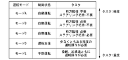
- FIG. 4 is a diagram showing an example of the correspondence between the driving mode, the control state of the vehicle M, and the task.
- the operation mode of the vehicle M includes, for example, five modes from mode A to mode E.
- the degree of automation of the control state that is, the operation control of the vehicle M, is highest in mode A, then in the order of mode B, mode C, and mode D, and is lowest in mode E.
- the task imposed on the driver is the mildest in mode A, followed by mode B, mode C, and mode D in that order, and mode E is the most severe. Since the modes D and E are in a control state that is not automatic operation, the first control device 100 is responsible for ending the control related to automatic operation and shifting to driving support or manual operation.
- the contents of each operation mode will be illustrated.
- mode A the vehicle is in an automatic driving state, and neither forward monitoring (or monitoring around the vehicle M) nor gripping of the steering wheel 82 (steering gripping in the figure) is imposed on the driver.
- the driver is required to be in a position to quickly shift to manual operation in response to a request from the system centered on the first control device 100.
- automated driving as used herein means that both steering and acceleration / deceleration are controlled without depending on the driver's operation.
- the front means the space in the traveling direction of the vehicle M which is visually recognized through the front windshield.
- mode A for example, on a motorway such as an expressway, the vehicle M is traveling at a predetermined speed (for example, about 50 [km / h]) or less, and there is a condition that a preceding vehicle to be followed exists. It is an operation mode that can be executed when it is satisfied, and is sometimes called TJP (Traffic Jam Pilot). When this condition is no longer satisfied, the mode determination unit 150 changes the driving mode of the vehicle M to the mode B.
- a predetermined speed for example, about 50 [km / h]
- TJP Traffic Jam Pilot
- Mode B the driver is in a driving support state, and the driver is tasked with monitoring the front of the vehicle M (hereinafter referred to as “forward monitoring”) (or monitoring around the vehicle M), but the steering wheel. The task of grasping the 82 is not imposed.
- mode C the driving support state is set, and the driver is tasked with the task of forward monitoring and the task of gripping the steering wheel 82.
- Mode D is a driving mode that requires a certain degree of driving operation by the driver with respect to at least one of steering and acceleration / deceleration of the vehicle M.
- driving support such as ACC (Adaptive Cruise Control) or LKAS (Lane Keeping Assist System) is provided.
- both steering and acceleration / deceleration are in a state of manual operation that requires a driving operation by the driver.
- the driver is naturally tasked with monitoring the front of the vehicle M.
- peripheral monitoring may be imposed instead of forward monitoring.
- the periphery means the space around the own vehicle M that the driver sees during manual driving. In the following description, it is assumed that "forward monitoring" is imposed.
- the first control device 100 executes the lane change according to the driving mode.
- the lane change includes a lane change (1) according to a system request and a lane change (2) according to a driver request.
- the lane change (1) is to change the lane for overtaking and to proceed toward the destination, which is performed when the speed of the vehicle in front is smaller than the standard with respect to the speed of the own vehicle.
- There is a lane change (a lane change due to a change in the recommended lane).
- the lane change (2) changes the lane of the own vehicle M toward the operation direction when the direction indicator is operated by the driver when the conditions related to the speed and the positional relationship with the surrounding vehicles are satisfied. It is something that makes you.
- the first control device 100 does not execute either the lane change (1) or (2) in the mode A.
- the first control device 100 executes both of the lane changes (1) and (2) in modes B and C.
- the driving support device (not shown) does not execute the lane change (1) but executes the lane change (2) in the mode D.
- mode E neither lane change (1) nor (2) is executed.
- the mode determination unit 150 changes the operation mode of the vehicle M to an operation mode in which the task is more severe when the task related to the determined operation mode (hereinafter referred to as the current operation mode) is not executed by the driver.
- the mode determination unit 150 urges the driver to shift to manual driving by using the HMI 30 and a predetermined output unit that encourages the occupant to grip the steering wheel, and if the driver does not respond, the vehicle M is gradually moved to the road shoulder and gradually. Controls such as stopping the automatic operation and stopping the automatic operation. After the automatic driving is stopped, the vehicle M is in the mode D or E, and the vehicle M can be started by the manual operation of the driver.
- stop automatic operation the same applies to "stop automatic operation”.
- the mode determination unit 150 prompts the driver to monitor the front using the HMI 30 or a predetermined output unit, and if the driver does not respond, the vehicle M is moved to the shoulder. Control is performed such as gradually stopping and stopping automatic operation.
- the mode determination unit 150 uses the HMI 30 or a predetermined output unit to monitor the driver forward and / or The steering wheel 82 is urged to be gripped, and if the driver does not respond, the vehicle M is brought closer to the road shoulder and gradually stopped, and automatic driving is stopped.
- the driver state determination unit 152 monitors the driver's state for the above mode change, and determines whether or not the driver's state is in a state corresponding to the task. For example, the driver state determination unit 152 analyzes the image captured by the driver monitor camera 70 and performs posture estimation processing, and whether or not the driver is in a position where he / she cannot shift to manual driving in response to a request from the system. To judge. The driver state determination unit 152 analyzes the image captured by the driver monitor camera 70, performs line-of-sight estimation processing, and determines whether or not the driver is monitoring the front.
- the mode change processing unit 154 performs various processes for changing the mode. For example, the mode change processing unit 154 instructs the action plan generation unit 140 to generate a target trajectory for shoulder stop, gives an operation instruction to a driving support device (not shown), and gives an action to the driver. HMI30 is controlled to encourage.
- the abnormality determination unit 156 is a device related to the combination switch 90, the combination switch connected between the first control device 100 and the combination switch 90 via a communication line (multifunctional integrated control device 92, instrument device 94, multifunction integrated). It is determined whether or not an abnormality has occurred in the communication performed by the control device 92) or the combination switch 90 and the first control device 100. Details will be described later.
- the second control unit 160 controls the traveling driving force output device 200, the brake device 210, and the steering device 220 so that the vehicle M passes the target track generated by the action plan generation unit 140 at the scheduled time. do.
- the second control unit 160 includes, for example, an acquisition unit 162, a speed control unit 164, and a steering control unit 166.
- the acquisition unit 162 acquires the information of the target trajectory (orbit point) generated by the action plan generation unit 140 and stores it in a memory (not shown).
- the speed control unit 164 controls the traveling drive force output device 200 via the drive ECU 252 described later based on the speed element accompanying the target trajectory stored in the memory, and brakes via the braking ECU (260 or 362). It controls the device 210.
- the steering control unit 166 controls the steering device 220 via the steering ECU (250 or 350) according to the degree of bending of the target trajectory stored in the memory.
- the processing of the speed control unit 164 and the steering control unit 166 is realized by, for example, a combination of feedforward control and feedback control.
- the steering control unit 166 executes a combination of feedforward control according to the curvature of the road in front of the vehicle M and feedback control based on the deviation from the target track.
- the speed control unit 164 may be integrated into the drive ECU 252 or the braking ECU.
- the steering control unit 166 may be integrated into the steering ECU.
- the traveling driving force output device 200 outputs the traveling driving force (torque) for the vehicle M to travel to the drive wheels.
- the traveling driving force output device 200 is, for example, a combination of an internal combustion engine, an electric motor, a transmission, and the like.
- the brake device 210 includes, for example, a brake caliper, a cylinder that transmits hydraulic pressure to the brake caliper, and an electric motor that generates hydraulic pressure in the cylinder.
- the brake device 210 may include a mechanism for transmitting the hydraulic pressure generated by the operation of the brake pedal included in the operation operator 80 to the cylinder via the master cylinder as a backup.
- the brake device 210 is not limited to the configuration described above, and may be an electronically controlled hydraulic brake device that controls the actuator according to the information input from the second control unit 160 to transmit the hydraulic pressure of the master cylinder to the cylinder. ..
- the steering device 220 includes, for example, an electric motor.
- the electric motor for example, exerts a force on the rack and pinion mechanism to change the direction of the steering wheel.
- the camera 310 is, for example, a digital camera that uses a solid-state image sensor such as a CCD or CMOS.
- the camera 310 is attached to any part of the vehicle M.
- the camera 310 periodically and repeatedly images the periphery of the vehicle M, for example.
- the camera 10 may be a stereo camera.
- the radar device 312 radiates radio waves such as millimeter waves around the vehicle M, and also detects radio waves (reflected waves) reflected by the object to detect at least the position (distance and direction) of the object.
- the radar device 312 is attached to an arbitrary position on the vehicle M.
- the radar device 312 may detect the position and velocity of the object by the FM-CW (Frequency Modified Continuous Wave) method.
- the second control device 320 includes, for example, a second recognition unit 330, a vehicle control unit 340, and a second monitoring unit 342.
- the second recognition unit 330, the vehicle control unit 340, and the second monitoring unit 342 are realized by, for example, a hardware processor such as a CPU executing a program (software). Some or all of these components may be realized by hardware such as LSI, ASIC, FPGA, GPU (circuit part; including circuitry), or realized by the cooperation of software and hardware. May be good.
- the program may be stored in advance in a device (a storage device including a non-transient storage medium) such as an HDD or a flash memory of the second control device 320, or a detachable storage such as a DVD or a CD-ROM. It is stored in a medium, and may be installed in the HDD or flash memory of the second control device 320 by mounting the storage medium (non-transient storage medium) in the drive device.
- the second recognition unit 330 performs sensor fusion processing on the detection results of a part or all of the camera 310 and the radar device 312, and recognizes the position, type, speed, etc. of the object.
- the vehicle control unit 340 executes the same processing as the first control unit 120 and the second control unit 160 to execute the automatic operation of the vehicle M.
- the processing performance of the first control unit 120 and the second control unit 160 (first control device 100) is higher than the processing performance of the vehicle control unit 340 (second control device 320).
- the reliability of the processing performance of the first control unit 120 and the second control unit 160 is higher than the reliability of the processing performance of the vehicle control unit 340. Therefore, the automatic driving by the first control unit 120 and the second control unit 160 is smoother than the automatic driving by the vehicle control unit 340.
- the details of the second monitoring unit 342 will be described later.
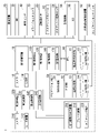
- FIG. 5 is a diagram showing the vehicle system 1 from another viewpoint. The first group and the second group will be described with reference to FIG. The description of the functional configuration described with reference to FIGS. 1 and 3 will be omitted.
- Group 1 Camera 10, LIDAR 14, 1st recognition device 16, MPU60, 1st control device 100, steering ECU (Electronic Control Unit) 250, drive ECU 252, braking ECU 260, stop holding ECU 262, 1st notification ECU 264, multifunctional integrated control device 92,
- the HUD 96, the multifunction integrated control unit 92, and the GW 280 are included in, for example, the first group.
- the steering ECU 250 controls the steering device 220 in cooperation with the first control device 100.
- the steering ECU 250 drives the electric motor according to the information input from the second control unit 160 to change the direction of the steering wheel.
- the steering ECU 250 controls steering according to the driver's operation on the steering wheel.
- the steering ECU 250 controls steering by using information input from an electric motor that outputs a driving force for steering, a sensor that detects the amount of rotation of the electric motor, and a torque sensor that detects steering torque, and controls these information. It may be provided to the second control unit 160.
- the drive ECU 252 controls the traveling drive force output device 200 in cooperation with the first control device 100.
- the drive ECU 252 controls the traveling drive force output device 200 according to the information input from the sensor provided in the operation controller 80.
- the drive ECU 252 controls the internal combustion engine or the electric motor or switches the shift stage of the automatic transmission based on the information input from the sensor that detects the operation amount of the accelerator pedal, the operation amount of the brake pedal, and the vehicle speed, for example. Or something.
- the braking ECU 260 controls the braking device 210 in cooperation with the first control device 100.
- the braking ECU 260 controls the electric motor according to the information input from the second control unit 160 so that the braking torque corresponding to the braking operation is output to each wheel.
- the braking ECU 260 and the braking device 210 function as, for example, an electric servo brake (ESB).
- EBS electric servo brake
- the braking ECU 260 controls, for example, the distribution of the braking force due to the braking device 210 and the braking force due to the regenerative braking of the electric motor.
- the stop holding ECU 262 controls the electric parking lock device provided in the automatic transmission.
- the electric parking lock device locks the internal mechanism of the automatic transmission, for example, when the P range (parking range) is selected.
- the first notification ECU 264 controls an in-vehicle output unit that notifies information in the vehicle.
- the in-vehicle output unit includes, for example, an output unit provided on the steering wheel. This output unit is lit, for example, when the occupant of the vehicle M needs to grip the steering wheel.
- the in-vehicle output unit also includes a mechanism that vibrates the seat belt to encourage the occupant to grip the steering wheel and perform a predetermined operation.
- the GW280 relays the communication line CL-A and the communication line CL-B.
- a camera 10 a first recognition device 16, a first control device 100, a drive ECU 252, a braking ECU 260, a stop holding ECU 262, a first notification ECU 264, and an external notification ECU 266 are connected to the communication line CL-A.
- a camera 310, a radar device 312, a second control device 320, a braking ECU 362, a stop holding ECU 364, and a second notification ECU 366 are connected to the communication line CL-B.
- HUD96 is connected to GW280 via a communication line.
- the multifunctional integrated control device 92 is connected to the HUD96 and further connected to the instrument device 94 of the second group.
- the steering grip sensor 84, the instrument device 94, the camera 310, the radar device 312, the second control device 320, the steering ECU 350, the braking ECU 362, the stop holding ECU 364, the steering grip sensor 84, and the instrument device 94 are included in, for example, the second group. Is done.
- the steering ECU 350 controls the steering device 220 in cooperation with the second control device 300.
- the steering ECU 250 controls steering using information input from an electric motor that outputs a driving force for steering, a sensor that detects the amount of rotation of the electric motor, and a torque sensor that detects steering torque.
- the braking ECU 362 controls the braking device 210 in cooperation with the second control device 300.
- the braking ECU 362 controls the electric motor according to the information input from the vehicle control unit 340 so that the braking torque corresponding to the braking operation is output to each wheel.
- the braking ECU 362 realizes VSA (Vehicle Stability Assist). Based on the detection results of the yaw rate sensor and the acceleration sensor, the braking ECU 362 suppresses the wheels from locking and slipping when the brakes are applied on a sudden brake or a low friction road, and the wheels are started or stopped. It suppresses the idling of the vehicle, and further controls the posture of the vehicle M when turning to suppress the occurrence of skidding.
- VSA Vehicle Stability Assist
- the stop holding ECU 364 controls the electric parking brake (EPB) to keep the vehicle M stopped.
- the electric parking brake has a mechanism for locking the rear wheels.
- the stop holding ECU 364 controls the electric parking brake to lock and unlock the rear wheels.
- the steering grip sensor 84 is connected to the instrument device 94 via a communication line.
- the instrument device 94 is connected to the communication line CL-B and further connected to the multifunction integrated control device 92 as described above.
- the first monitoring unit 170 monitors the state of a part or all of the functional configurations (devices having the functional configurations) included in the second group connected via the GW 280.
- the first monitoring unit 170 acquires, for example, the information transmitted by the communication-destination device, and determines whether or not an abnormality exists in the communication-destination device based on the acquired information.
- the existence of an abnormality is, for example, a state in which the communication destination device cannot be controlled to the state intended by the second control device 320.
- the existence of an abnormality includes, for example, a defect in the device, a defect in the function of the device, a deterioration in the function, a state in which communication with the device is different from the standard communication state, and the like.
- the information transmitted by the communication-destination device is the result of self-diagnosis of the connection-destination device or a predetermined flag transmitted from the connection-destination device. For example, when the connection-destination device transmits information including a self-diagnosis result indicating an abnormality and a flag indicating an abnormality, the first monitoring unit 170 determines that the communication-destination device has an abnormality. Further, when the first monitoring unit 170 cannot communicate with the connected device or the communication is delayed, it may be considered that the communication destination device has an abnormality.
- the second monitoring unit 342 monitors the state of a part or all of the functional configurations included in the first group connected via the GW280.
- the second monitoring unit 342 acquires the information transmitted by the communication destination device, and determines whether or not an abnormality exists in the communication destination device based on the acquired information.
- the existence of an abnormality is, for example, a state in which the communication destination device cannot be controlled to the state intended by the first control device 100.
- the existence of an abnormality includes, for example, a defect in the device, a defect in the function of the device, a deterioration in the function, a state in which communication with the device is different from the standard communication state, and the like.
- the abnormality of the communication destination device includes, for example, a state similar to the state described in the description of the first monitoring unit 170.
- the second control device 320 executes automatic operation in place of the first control device 100 when an abnormality occurs in a device or device included in the first group. For example, among the devices and devices included in the first group, when an abnormality occurs in the steering ECU 250, the braking ECU 260, the stop holding ECU 262, or these devices and devices to be controlled, the second control device 320 sets the steering ECU 350. The braking ECU 362, the stop holding ECU 364, or these controlled devices and devices are controlled to execute automatic operation.
- the automatic operation in this case is, for example, an automatic operation in a FOF (Fail Operation Function) mode (degenerate control mode).
- FOF Flexible Operation Function
- the vehicle system 1 requests the driver to manually operate the vehicle M, and the vehicle M does not deviate from the road for a predetermined time (or a predetermined distance), and the vehicle is in the vicinity of the vehicle. This mode controls M so as not to approach it excessively. If the vehicle is not manually operated for a predetermined time, the vehicle system 1 decelerates the vehicle M and stops the vehicle M as it is, or stops the vehicle M at a position where the vehicle M can be stopped.
- the vehicle system 1 includes, for example, a large capacity battery 400, a first power supply unit 410, a first battery 420, a second power supply unit 430, and a second battery 440.
- the large capacity battery 400 is a rechargeable battery such as a lithium ion battery.
- the driving motor is driven by the electric power supplied by the large-capacity battery 400.
- the large-capacity battery 400 is charged with the regenerative power generated by the electric motor.
- the first power supply unit 410 steps down the output voltage of the large capacity battery 400 and supplies the power of the large capacity battery 400 to each functional configuration of the first group.
- the first battery 420 is, for example, a 12V lead battery.
- the power of the first battery 420 is supplied to the functional configuration of the first group, for example, when the large capacity battery 400 does not supply power to the functional configuration of the first group. Further, the first battery 420 supplies electric power to some sensors included in the navigation device 50, the communication device 20, the driver monitor camera 70, and the vehicle sensor 40.
- the second power supply unit 430 steps down the output voltage of the large capacity battery 400 and supplies the power of the large capacity battery 400 to each functional configuration of the second group.
- the second battery 440 is, for example, a 12V lead battery.
- the electric power of the second battery 440 is supplied to the functional configuration of the second group, for example, when the electric power is not supplied from the large capacity battery 400 to the functional configuration of the second group. Further, the second battery 440 supplies electric power to the steering grip sensor 84 and some of the sensors included in the vehicle sensor 40.
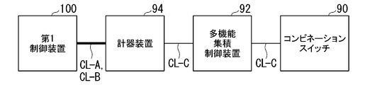
- FIG. 6 is a diagram for explaining a connection state regarding communication between the first control device 100, the instrument device 94, the multifunctional integrated control device 92, and the combination switch 90 of the multifunctional integrated control device 92.
- the first control device 100 and the instrument device 94 are connected to each other via the communication line CL-A and the communication line CL-B.
- the instrument device 94 and the multifunctional integrated control device 92 are connected via a communication line CL-C.
- the multifunctional integrated control device 92 and the combination switch 90 are connected via the communication line CL-C.
- the communication speed of communication performed using the communication line CL-A and the communication line CL-B is faster than the communication speed of the communication performed using the communication line CL-C.
- Communication using so-called F-CAN is performed between the devices to which the communication line CL-A or the communication line CL-B is connected.
- Communication using so-called B-CAN is performed between the devices to which the communication lines CL-C are connected.
- the instrument device 94 is interposed between the first control device 100 and the multifunctional integrated control device 92, but instead of these devices, one or more other devices are used.
- the device may intervene.
- one or more other devices may intervene between the multifunctional integrated control device 92 and the combination switch 90.
- One of the instrument device 94 and the multifunctional integrated control device 92 may be omitted, and the first control device 100 and the combination switch 90 may communicate with each other.
- the abnormality determination unit 156 determines that an abnormality has occurred in the equipment related to the combination switch when an abnormality occurs in the control target of the combination switch 90, the instrument device 94, the multi-function integrated control device 92, or the multi-function integrated control device 92. do.
- the control target of the multifunctional integrated control device 92 is, for example, a drive unit for driving a wiper, a device or device for controlling a light, a device or device for controlling a turn signal, or the like.
- the abnormality determination unit 156 communicates between the combination switch 90 and the first control unit 120 when a defect occurs in the communication using the communication line CL-A, the communication line CL-B, or the communication line CL-C described above. It is determined that an abnormality has occurred in.
- these details will be described.
- FIG. 7 is a diagram for explaining an abnormality determination condition and a presumed abnormality.
- the abnormality determination unit 156 receives information indicating a failure of the combination switch 90 from the instrument device 94 and the state continues for the first time (for example, 1 [s]), or (2) from the instrument device 94.
- the combination switch 90 fails, and the communication between the combination switch 90 and the multifunction integrated control device 92. It is presumed that a defect in the line CL-C or a failure of the multifunctional integrated control device 92 has occurred.
- the reception of the information indicating the failure may include the reception of the flag indicating the failure and the state in which the information cannot be received from the communication destination device (for example, no signal). For example, when the abnormality determination unit 156 receives a flag indicating a failure from the communication destination device or cannot receive a predetermined signal from the communication destination device for the first time, the above (1) or ( It may be determined that it corresponds to 2).
- the abnormality determination unit 156 receives information indicating that the turn lever is in the mechanical lock state from the instrument device 94, it is presumed that the turn lever is in the mechanical lock state and an abnormality has occurred in the turn lever.
- the mechanical lock is, for example, from the operation position where the first operation lever 90A is operated in the operation direction (vertical direction) for lighting the right winker, and the first operation lever 90A is operated to light the right winker by the operation. Also moves in the vertical direction, and the first operating lever 90A is fixed at that position by a mechanical mechanism.
- the abnormality determination unit 156 receives information indicating that the wiper switch has failed and the state continues for the second time (for example, 1 [s]), the wiper switch fails, and the wiper switch and the multi-function integration. It is presumed that a defect in the communication line CL-C with the control device 92 or a failure in the multifunctional integrated control device 92 has occurred.
- the abnormality determination unit 156 receives information from the instrument device 94 indicating that the multifunctional integration control device 92 has failed and the state continues for the third time (for example, 1 [s]), the multifunctional integration is performed. It is presumed that a failure of the control device 92, a defect of the communication line CL-C between the multifunctional integrated control device 92 and the instrument device 94, or a failure of the instrument device 94 has occurred.
- the abnormality determination unit 156 may perform only a part of the determination processes (1)-(5) above.
- FIG. 8 is a diagram for explaining a condition for starting the determination of FIGS. 7 (1) to (5).
- the determination of (1), (2), (4), and (5) in FIG. 7 is started when all of the following conditions (a)-(c) are satisfied.
- (A) The state in which the voltage input to the first control device 100 is equal to or higher than the first voltage (for example, 10 V or higher) has elapsed for the fourth time (for example, 5 [s]).
- B The communication state between the first control device 100 and the instrument device 94 is normal.
- C No abnormality has occurred in communication using the communication line CL-C connected to the instrument device 94.
- the determination in (3) of FIG. 6 is always performed. For example, it is performed from the time when the power of the vehicle M is turned on to the time when the power of the vehicle M is turned off.
- FIG. 9 is a flowchart showing an example of the flow of processing executed by the abnormality determination unit 156 of the first control device 100.
- This process is a process for determining whether or not to start the determination of (1), (2), (4), and (5) of FIG. This process is started, for example, when the power of the vehicle M is turned on.
- the abnormality determination unit 156 determines whether or not a state in which a voltage equal to or higher than the first voltage has been input to the first control device 100 has elapsed for the fourth time (step S100). When the state in which the voltage equal to or higher than the first voltage is input has elapsed for the fourth time, the abnormality determination unit 156 determines whether or not the communication with the instrument device 94 is normal (step S102).
- the abnormality determination unit 156 determines whether or not an abnormality has occurred in the communication using the communication line CL-C connected to the instrument device 94 (step S104). .. When it is determined that no abnormality has occurred in the communication using the communication line CL-C connected to the instrument device 94, the abnormality determination unit 156 may perform the abnormality determination unit 156 in FIGS. 7 (1), (2), (4), and FIG. And the abnormality determination of (5) is started (step S106). If the determination in step S100, step S102, and step S104 is negative, one routine in this flowchart ends. The order of processing in step S100-step S104 may be changed.
- the vehicle system 1 can suppress unnecessary determination processing.
- FIG. 10 is a flowchart showing an example of the flow of processing executed by the mode determination unit 150.
- the abnormality determination unit 156 determines whether or not it has been determined to start the abnormality determination (step S200).
- the mode determination unit 150 determines that the abnormality determination unit 156 has an abnormality in the combination switch 90, the device related to the combination switch 90, or the communication between the combination switch 90 and the first control device 100. It is determined whether or not the determination is made (step S202).
- the abnormality determination unit 156 determines that an abnormality has occurred in the above-mentioned equipment or the like.
- the mode change processing unit 154 determines whether or not the operation mode is mode A (step S204). When the operation mode is mode A, the mode change processing unit 154 switches the operation mode to mode E (step S206). In this case, for example, the mode change processing unit 154 prompts the occupant of the vehicle M to perform the driving operation, and when the occupant performs the driving operation within a predetermined time, the mode change processing unit 154 switches the driving mode to the mode E. If the occupant does not perform the driving operation within a predetermined time, the first control device 100 more strongly urges the occupant of the vehicle M to perform the driving operation, decelerates the vehicle M, or puts the vehicle M in a predetermined position. To stop.
- step S202 or step S204 If the determination in step S202 or step S204 is negative, one routine in this flowchart ends.
- the vehicle system 1 can control the vehicle M more appropriately when an abnormality occurs.
- the mode change processing unit 154 has a mode change processing unit 154 in which the operation mode is a predetermined operation mode. In the case of (arbitrary mode such as mode B), the mode may be switched to the mode E. Further, the mode change processing unit 154 may switch to any other operation mode instead of switching to the mode E.
- the other operation mode is a more severe operation mode than the operation mode targeted for the determination process in step S204.
- the first control device 100 controls the vehicle M in the second operation mode, and the combination switch, the first control device 100 and the combination switch 90 are connected to each other via a communication line.
- the vehicle is made more appropriate by changing the operation mode to the first operation mode. Can be controlled to.
- a combination switch and a device that operates according to the combination switch 90 is a target controlled by the first control device 100 during automatic operation.
- the above-mentioned device is a device that can be controlled by the driver during automatic operation.
- the function of the first control device 100 to properly control the vehicle is impaired, or the driver's operation intention is appropriately reflected in the automatic driving. It may not be there.
- the first control device 100 when an abnormality occurs in the equipment or the like as described above, the first control device 100 appropriately changes the operation mode, so that the vehicle can be controlled more appropriately.
- a storage device that stores the program and With a hardware processor, When the hardware processor executes the program, Control one or both of the vehicle's steering or acceleration / deceleration,
- the driving mode of the vehicle is determined to be one of a plurality of driving modes including a first driving mode and a second driving mode, and the second driving mode is the task assigned to the driver. It is milder than the operation mode of 1, and one or both of steering or acceleration / deceleration of the vehicle is controlled without depending on the operation of the driver of the vehicle.
- the vehicle is controlled in the second operation mode, and the combination switch, the device related to the combination switch connected between the computer and the combination switch via a communication line, or the combination switch and the computer.
- the operation mode is changed to the first operation mode.
- a vehicle control unit configured as such.
- 1 vehicle system 10 camera, 16 first recognition device, 20 communication device, 40 vehicle sensor, 50 navigation device, 70 driver monitor camera, 80 driving controller, 82 steering wheel, 84 Steering grip sensor, 90 ... combination switch, 92 ... multi-function integrated control device, 94 ... instrument device, 100 ... first control device, 120 ... first control unit, 130 ... recognition unit, 140 ... action plan generation unit, 150 ... Mode determination unit, 152 ... Driver status determination unit, 154 ... Mode change processing unit, 160 ... Second control unit, 162 ... Acquisition unit, 164 ... Speed control unit, 166 ... Steering control unit, 170 ... First monitoring unit, 200 ... Driving drive force output device, 210 ... Brake device, 220 ... Steering device, 250 ...
- Steering ECU, 350 Steering ECU, 362 Braking ECU, 364 Stop holding ECU, 366 Second notification ECU, 400 Large capacity battery, 410 First power supply unit, 420 First battery, 430 Second Power supply, 440 ... 2nd battery
Abstract
Priority Applications (4)
| Application Number | Priority Date | Filing Date | Title |
|---|---|---|---|
| CN202080107872.1A CN116670004A (zh) | 2020-12-28 | 2020-12-28 | 车辆控制装置、车辆系统、车辆控制方法及程序 |
| PCT/JP2020/049103 WO2022144959A1 (fr) | 2020-12-28 | 2020-12-28 | Appareil de commande de véhicule, système de véhicule, procédé de commande de véhicule et programme |
| US18/268,626 US11919547B1 (en) | 2020-12-28 | 2020-12-28 | Vehicle control device, vehicle system, vehicle control method, and program |
| JP2022527924A JP7223914B2 (ja) | 2020-12-28 | 2020-12-28 | 車両制御装置、および車両システム |
Applications Claiming Priority (1)
| Application Number | Priority Date | Filing Date | Title |
|---|---|---|---|
| PCT/JP2020/049103 WO2022144959A1 (fr) | 2020-12-28 | 2020-12-28 | Appareil de commande de véhicule, système de véhicule, procédé de commande de véhicule et programme |
Publications (1)
| Publication Number | Publication Date |
|---|---|
| WO2022144959A1 true WO2022144959A1 (fr) | 2022-07-07 |
Family
ID=82260358
Family Applications (1)
| Application Number | Title | Priority Date | Filing Date |
|---|---|---|---|
| PCT/JP2020/049103 WO2022144959A1 (fr) | 2020-12-28 | 2020-12-28 | Appareil de commande de véhicule, système de véhicule, procédé de commande de véhicule et programme |
Country Status (4)
| Country | Link |
|---|---|
| US (1) | US11919547B1 (fr) |
| JP (1) | JP7223914B2 (fr) |
| CN (1) | CN116670004A (fr) |
| WO (1) | WO2022144959A1 (fr) |
Families Citing this family (2)
| Publication number | Priority date | Publication date | Assignee | Title |
|---|---|---|---|---|
| KR102486114B1 (ko) * | 2018-09-04 | 2023-01-09 | 현대자동차주식회사 | 통신 장치, 그를 가지는 차량 및 그 제어 방법 |
| CN116923458B (zh) * | 2023-09-18 | 2023-12-01 | 宁波均联智行科技股份有限公司 | 一种车辆驾驶控制方法、装置及介质 |
Citations (5)
| Publication number | Priority date | Publication date | Assignee | Title |
|---|---|---|---|---|
| JPS632750A (ja) * | 1986-06-20 | 1988-01-07 | Matsushita Electric Ind Co Ltd | 電子化コンビネ−シヨンスイツチ |
| JP2017224266A (ja) * | 2016-06-13 | 2017-12-21 | 三星ディスプレイ株式會社Samsung Display Co.,Ltd. | タッチセンサ及びこれを用いたタッチ検知方法 |
| JP2018180843A (ja) * | 2017-04-11 | 2018-11-15 | 株式会社デンソー | 車両のデータ記憶装置 |
| JP6678905B1 (ja) * | 2019-09-13 | 2020-04-15 | 山内 和博 | 自動運転車 |
| KR20200068770A (ko) * | 2018-11-27 | 2020-06-16 | (주)언맨드솔루션 | 자율주행 긴급제어 시스템 |
Family Cites Families (15)
| Publication number | Priority date | Publication date | Assignee | Title |
|---|---|---|---|---|
| JP6432188B2 (ja) | 2014-07-15 | 2018-12-05 | 株式会社デンソー | 灯火器制御装置および灯火器制御方法 |
| JP6937256B2 (ja) | 2018-03-12 | 2021-09-22 | 日立Astemo株式会社 | 車両制御装置、車両制御方法及び車両制御システム |
| GB2613740B (en) * | 2018-10-30 | 2023-12-06 | Motional Ad Llc | Redundancy in autonomous vehicles |
| JP6916233B2 (ja) | 2019-03-18 | 2021-08-11 | 本田技研工業株式会社 | 車両制御装置 |
| JP7252801B2 (ja) | 2019-03-19 | 2023-04-05 | 株式会社Subaru | 自動運転車両の交通制御システム |
| CN111891134B (zh) | 2019-05-06 | 2022-09-30 | 北京百度网讯科技有限公司 | 自动驾驶处理系统和片上系统、监测处理模块的方法 |
| CN110077420B (zh) * | 2019-05-23 | 2020-11-10 | 广州小鹏汽车科技有限公司 | 一种自动驾驶控制系统和方法 |
| US11285966B2 (en) * | 2019-05-29 | 2022-03-29 | Visteon Global Technologies, Inc. | Method and system for controlling an autonomous vehicle response to a fault condition |
| US11640342B2 (en) * | 2019-10-30 | 2023-05-02 | Ghost Autonomy Inc. | Fault state transitions in an autonomous vehicle |
| US11702110B2 (en) * | 2020-01-06 | 2023-07-18 | Nio Technology (Anhui) Co., Ltd. | Methods and systems to enhance safety of bi-directional transition between autonomous and manual driving modes |
| WO2021151501A1 (fr) * | 2020-01-31 | 2021-08-05 | Zf Cv Systems Global Gmbh | Architecture de système à sécurité intégrée asymétrique |
| CN111874001B (zh) * | 2020-06-09 | 2022-03-25 | 北京百度网讯科技有限公司 | 自动驾驶汽车的安全控制方法、电子设备及存储介质 |
| US11691637B2 (en) * | 2020-06-19 | 2023-07-04 | Ghost Autonomy Inc. | Handling input data errors in an autonomous vehicle |
| KR20220063856A (ko) * | 2020-11-10 | 2022-05-18 | 현대자동차주식회사 | 자율 주행 제어 방법 및 장치 |
| US11912302B2 (en) * | 2020-12-21 | 2024-02-27 | Zoox, Inc. | Autonomous control engagement |
-
2020
- 2020-12-28 US US18/268,626 patent/US11919547B1/en active Active
- 2020-12-28 CN CN202080107872.1A patent/CN116670004A/zh active Pending
- 2020-12-28 WO PCT/JP2020/049103 patent/WO2022144959A1/fr active Application Filing
- 2020-12-28 JP JP2022527924A patent/JP7223914B2/ja active Active
Patent Citations (5)
| Publication number | Priority date | Publication date | Assignee | Title |
|---|---|---|---|---|
| JPS632750A (ja) * | 1986-06-20 | 1988-01-07 | Matsushita Electric Ind Co Ltd | 電子化コンビネ−シヨンスイツチ |
| JP2017224266A (ja) * | 2016-06-13 | 2017-12-21 | 三星ディスプレイ株式會社Samsung Display Co.,Ltd. | タッチセンサ及びこれを用いたタッチ検知方法 |
| JP2018180843A (ja) * | 2017-04-11 | 2018-11-15 | 株式会社デンソー | 車両のデータ記憶装置 |
| KR20200068770A (ko) * | 2018-11-27 | 2020-06-16 | (주)언맨드솔루션 | 자율주행 긴급제어 시스템 |
| JP6678905B1 (ja) * | 2019-09-13 | 2020-04-15 | 山内 和博 | 自動運転車 |
Also Published As
| Publication number | Publication date |
|---|---|
| JP7223914B2 (ja) | 2023-02-16 |
| US11919547B1 (en) | 2024-03-05 |
| JPWO2022144959A1 (fr) | 2022-07-07 |
| US20240051583A1 (en) | 2024-02-15 |
| CN116670004A (zh) | 2023-08-29 |
Similar Documents
| Publication | Publication Date | Title |
|---|---|---|
| JP6942236B1 (ja) | 車両制御装置、車両制御方法、およびプログラム | |
| WO2022144959A1 (fr) | Appareil de commande de véhicule, système de véhicule, procédé de commande de véhicule et programme | |
| JP7194224B2 (ja) | 車両制御装置、車両制御方法、およびプログラム | |
| JP2022096236A (ja) | 車両制御装置、車両制御方法、及びプログラム | |
| US20230303099A1 (en) | Vehicle control device, vehicle control method, and storage medium | |
| US20230075153A1 (en) | Arithmetic device | |
| JP6936380B1 (ja) | 車両制御システム、および車両制御方法 | |
| US11628744B2 (en) | Vehicle control device, vehicle control method, and storage medium | |
| JP2023030147A (ja) | 車両制御装置、車両制御方法、およびプログラム | |
| JP7308880B2 (ja) | 車両制御装置、車両制御方法、およびプログラム | |
| JP7092955B1 (ja) | 車両制御装置、車両制御方法、およびプログラム | |
| JP7046291B1 (ja) | 車両制御システム、および車両制御方法 | |
| WO2022144963A1 (fr) | Dispostif de commande de véhicule, système de commande de véhicule, procédé de commande de véhicule, et programme | |
| JP7177968B1 (ja) | 車両制御装置、車両制御方法、およびプログラム | |
| JP7201657B2 (ja) | 車両制御装置、車両制御方法、およびプログラム | |
| JP7132447B1 (ja) | 車両制御装置、車両制御方法、およびプログラム | |
| WO2022144976A1 (fr) | Dispositif de commande de véhicule, procédé de commande de véhicule, et programme | |
| JP7112479B2 (ja) | 車両制御装置、車両制御方法、およびプログラム | |
| WO2022144974A1 (fr) | Dispositif de commande de véhicule, procédé de commande de véhicule et programme | |
| JP2022103723A (ja) | 車両制御装置、車両制御方法、およびプログラム |
Legal Events
| Date | Code | Title | Description |
|---|---|---|---|
| ENP | Entry into the national phase |
Ref document number: 2022527924 Country of ref document: JP Kind code of ref document: A |
|
| 121 | Ep: the epo has been informed by wipo that ep was designated in this application |
Ref document number: 20967972 Country of ref document: EP Kind code of ref document: A1 |
|
| WWE | Wipo information: entry into national phase |
Ref document number: 202080107872.1 Country of ref document: CN |
|
| WWE | Wipo information: entry into national phase |
Ref document number: 18268626 Country of ref document: US |
|
| NENP | Non-entry into the national phase |
Ref country code: DE |
|
| 122 | Ep: pct application non-entry in european phase |
Ref document number: 20967972 Country of ref document: EP Kind code of ref document: A1 |