WO2022144954A1 - Dispositif de commande de véhicule, procédé de commande de véhicule et programme - Google Patents
Dispositif de commande de véhicule, procédé de commande de véhicule et programme Download PDFInfo
- Publication number
- WO2022144954A1 WO2022144954A1 PCT/JP2020/049092 JP2020049092W WO2022144954A1 WO 2022144954 A1 WO2022144954 A1 WO 2022144954A1 JP 2020049092 W JP2020049092 W JP 2020049092W WO 2022144954 A1 WO2022144954 A1 WO 2022144954A1
- Authority
- WO
- WIPO (PCT)
- Prior art keywords
- vehicle
- mode
- driving mode
- driver
- driving
- Prior art date
Links
- 238000000034 method Methods 0.000 title claims description 14
- 230000001133 acceleration Effects 0.000 claims abstract description 22
- 238000013459 approach Methods 0.000 claims description 3
- 230000003247 decreasing effect Effects 0.000 claims description 3
- 230000008859 change Effects 0.000 description 47
- 238000012545 processing Methods 0.000 description 40
- 230000009471 action Effects 0.000 description 13
- 238000010586 diagram Methods 0.000 description 12
- 238000012544 monitoring process Methods 0.000 description 10
- 238000004891 communication Methods 0.000 description 9
- 230000006870 function Effects 0.000 description 7
- 230000008569 process Effects 0.000 description 6
- 238000001514 detection method Methods 0.000 description 4
- 238000002485 combustion reaction Methods 0.000 description 3
- 230000004044 response Effects 0.000 description 3
- 238000005070 sampling Methods 0.000 description 3
- 238000013473 artificial intelligence Methods 0.000 description 2
- 230000005484 gravity Effects 0.000 description 2
- 230000007246 mechanism Effects 0.000 description 2
- 230000001052 transient effect Effects 0.000 description 2
- 230000003044 adaptive effect Effects 0.000 description 1
- 230000003542 behavioural effect Effects 0.000 description 1
- 238000005452 bending Methods 0.000 description 1
- 230000005540 biological transmission Effects 0.000 description 1
- 230000001413 cellular effect Effects 0.000 description 1
- 230000000295 complement effect Effects 0.000 description 1
- 238000012790 confirmation Methods 0.000 description 1
- 238000007796 conventional method Methods 0.000 description 1
- 230000036461 convulsion Effects 0.000 description 1
- 238000013135 deep learning Methods 0.000 description 1
- 239000000446 fuel Substances 0.000 description 1
- 238000007499 fusion processing Methods 0.000 description 1
- 230000010354 integration Effects 0.000 description 1
- 229910044991 metal oxide Inorganic materials 0.000 description 1
- 150000004706 metal oxides Chemical class 0.000 description 1
- 238000012986 modification Methods 0.000 description 1
- 230000004048 modification Effects 0.000 description 1
- 230000002093 peripheral effect Effects 0.000 description 1
- 239000004065 semiconductor Substances 0.000 description 1
- 238000006467 substitution reaction Methods 0.000 description 1
Images


Classifications
-
- B—PERFORMING OPERATIONS; TRANSPORTING
- B60—VEHICLES IN GENERAL
- B60W—CONJOINT CONTROL OF VEHICLE SUB-UNITS OF DIFFERENT TYPE OR DIFFERENT FUNCTION; CONTROL SYSTEMS SPECIALLY ADAPTED FOR HYBRID VEHICLES; ROAD VEHICLE DRIVE CONTROL SYSTEMS FOR PURPOSES NOT RELATED TO THE CONTROL OF A PARTICULAR SUB-UNIT
- B60W30/00—Purposes of road vehicle drive control systems not related to the control of a particular sub-unit, e.g. of systems using conjoint control of vehicle sub-units
- B60W30/08—Active safety systems predicting or avoiding probable or impending collision or attempting to minimise its consequences
-
- B—PERFORMING OPERATIONS; TRANSPORTING
- B60—VEHICLES IN GENERAL
- B60W—CONJOINT CONTROL OF VEHICLE SUB-UNITS OF DIFFERENT TYPE OR DIFFERENT FUNCTION; CONTROL SYSTEMS SPECIALLY ADAPTED FOR HYBRID VEHICLES; ROAD VEHICLE DRIVE CONTROL SYSTEMS FOR PURPOSES NOT RELATED TO THE CONTROL OF A PARTICULAR SUB-UNIT
- B60W30/00—Purposes of road vehicle drive control systems not related to the control of a particular sub-unit, e.g. of systems using conjoint control of vehicle sub-units
- B60W30/10—Path keeping
-
- B—PERFORMING OPERATIONS; TRANSPORTING
- B60—VEHICLES IN GENERAL
- B60W—CONJOINT CONTROL OF VEHICLE SUB-UNITS OF DIFFERENT TYPE OR DIFFERENT FUNCTION; CONTROL SYSTEMS SPECIALLY ADAPTED FOR HYBRID VEHICLES; ROAD VEHICLE DRIVE CONTROL SYSTEMS FOR PURPOSES NOT RELATED TO THE CONTROL OF A PARTICULAR SUB-UNIT
- B60W30/00—Purposes of road vehicle drive control systems not related to the control of a particular sub-unit, e.g. of systems using conjoint control of vehicle sub-units
- B60W30/14—Adaptive cruise control
-
- B—PERFORMING OPERATIONS; TRANSPORTING
- B60—VEHICLES IN GENERAL
- B60W—CONJOINT CONTROL OF VEHICLE SUB-UNITS OF DIFFERENT TYPE OR DIFFERENT FUNCTION; CONTROL SYSTEMS SPECIALLY ADAPTED FOR HYBRID VEHICLES; ROAD VEHICLE DRIVE CONTROL SYSTEMS FOR PURPOSES NOT RELATED TO THE CONTROL OF A PARTICULAR SUB-UNIT
- B60W60/00—Drive control systems specially adapted for autonomous road vehicles
Definitions
- the present invention relates to a vehicle control device, a vehicle control method, and a program.
- the present invention has been made in consideration of such circumstances, and an object of the present invention is to provide a vehicle control device, a vehicle control method, and a program capable of performing appropriate control according to a situation at the time of being interrupted. It is one of.
- the vehicle control device has the following configuration. (1):
- the vehicle control device has a recognition unit that recognizes the surrounding conditions of the vehicle and an operation control that controls steering and acceleration / deceleration of the vehicle without depending on the operation of the driver of the vehicle.
- the operation mode of the unit and the vehicle is determined to be one of a plurality of operation modes including a first operation mode and a second operation mode, and the second operation mode is imposed on the driver.
- the task is a light operation mode as compared with the first operation mode, and at least a part of the plurality of operation modes including the second operation mode is controlled by the operation control unit.
- the recognition unit includes a mode determining unit that changes the driving mode of the vehicle to a driving mode in which the task is more severe when the task related to the determined driving mode is not executed by the driver, and the recognition unit is such that the vehicle travels. Recognizing an interrupting vehicle that is a vehicle interrupting the running path, the mode determining unit executes the second operation mode when the interrupting vehicle is recognized by the recognition unit and a predetermined condition is satisfied. It is a limitation.
- the second operation mode is an operation mode in which the driver is not tasked with grasping an operator that accepts a steering operation, and the first operation mode is.
- a driving mode that requires a driving operation by the driver for at least one of steering and acceleration / deceleration of the vehicle.
- the second operation mode is an operation mode in which the driver is not tasked with grasping an operator that accepts a steering operation
- the first operation mode is.
- the predetermined condition includes that the magnitude of the deceleration by the deceleration control becomes equal to or larger than the reference deceleration.
- the predetermined condition is that the vehicle and the interrupting vehicle approach each other at the end point of a section where the interrupting vehicle can interrupt the track on which the vehicle is traveling. Including that the degree is higher than the first standard degree.
- the predetermined condition includes that the elapsed time from the start of the deceleration control is equal to or longer than the first reference time.
- the predetermined condition is that the speed of the vehicle and the interrupting vehicle is equal to or lower than the first reference speed, and the vehicle and the preceding vehicle in front of the vehicle on the track. This includes the fact that the state in which the inter-vehicle distance is equal to or greater than the first reference inter-vehicle distance continues for the second reference time or longer.
- the predetermined condition includes that the speed of the vehicle has decreased by a second reference speed or more after the deceleration control is started.
- the predetermined condition includes the presence of another vehicle behind the interrupting vehicle whose distance from the interrupting vehicle is less than the second reference vehicle-to-vehicle distance. ..
- the computer mounted on the vehicle recognizes the surrounding situation of the vehicle, and steers the vehicle and steers the vehicle without relying on the operation of the driver of the vehicle.
- the acceleration / deceleration is controlled, the driving mode of the vehicle is determined to be one of a plurality of driving modes including a first driving mode and a second driving mode, and the second driving mode is given to the driver.
- the task to be imposed is a light operation mode as compared with the first operation mode, and at least a part of the plurality of operation modes including the second operation mode does not depend on the operation of the driver of the vehicle.
- the driving mode of the vehicle is changed to a driving mode in which the task is more severe.
- the interrupting vehicle which is a vehicle interrupting the track on which the vehicle is traveling, is recognized, and when the interrupting vehicle is recognized and a predetermined condition is satisfied, the second operation is performed. It limits the implementation of the mode.
- the program according to another aspect of the present invention causes a computer mounted on the vehicle to recognize the surrounding situation of the vehicle, and steers and accelerates / decelerates the vehicle without depending on the operation of the driver of the vehicle.
- the driving mode of the vehicle is determined to be one of a plurality of driving modes including a first driving mode and a second driving mode, and the second driving mode is imposed on the driver.
- the task is a light operation mode as compared with the first operation mode, and at least a part of the plurality of operation modes including the second operation mode is said to be independent of the operation of the driver of the vehicle.
- the driving mode of the vehicle is changed to a driving mode in which the task is more severe.
- the interrupting vehicle which is a vehicle interrupting the track on which the vehicle is traveling, is recognized, and the interrupting vehicle is recognized and a predetermined condition is satisfied, the second operation mode is used. It limits implementation.
- FIG. 1 is a configuration diagram of a vehicle system 1 using the vehicle control device according to the embodiment.
- the vehicle on which the vehicle system 1 is mounted is, for example, a vehicle such as a two-wheeled vehicle, a three-wheeled vehicle, or a four-wheeled vehicle, and the drive source thereof is an internal combustion engine such as a diesel engine or a gasoline engine, an electric motor, or a combination thereof.
- the electric motor operates by using the electric power generated by the generator connected to the internal combustion engine or the electric power generated by the secondary battery or the fuel cell.
- the vehicle system 1 includes, for example, a camera 10, a radar device 12, a LIDAR (Light Detection and Ringing) 14, an object recognition device 16, a communication device 20, an HMI (Human Machine Interface) 30, and a vehicle sensor 40. , Navigation device 50, MPU (Map Positioning Unit) 60, driver monitor camera 70, driving controller 80, automatic driving control device 100, traveling driving force output device 200, braking device 210, steering device 220. And prepare. These devices and devices are connected to each other by multiple communication lines such as CAN (Controller Area Network) communication lines, serial communication lines, wireless communication networks, and the like.
- CAN Controller Area Network
- the camera 10 is a digital camera that uses a solid-state image sensor such as a CCD (Charge Coupled Device) or a CMOS (Complementary Metal Oxide Semiconductor).
- the camera 10 is attached to an arbitrary position of the vehicle on which the vehicle system 1 is mounted (hereinafter referred to as the own vehicle M).
- the own vehicle M When photographing the front, the camera 10 is attached to the upper part of the front windshield, the back surface of the rear-view mirror, and the like.
- the camera 10 periodically and repeatedly images the periphery of the own vehicle M, for example.
- the camera 10 may be a stereo camera.
- the radar device 12 radiates radio waves such as millimeter waves around the own vehicle M, and also detects radio waves (reflected waves) reflected by the object to detect at least the position (distance and direction) of the object.
- the radar device 12 is attached to an arbitrary position on the own vehicle M.
- the radar device 12 may detect the position and velocity of the object by the FM-CW (Frequency Modified Continuous Wave) method.
- FM-CW Frequency Modified Continuous Wave
- the LIDAR14 irradiates the periphery of the own vehicle M with light (or an electromagnetic wave having a wavelength close to that of light) and measures scattered light.
- the LIDAR 14 detects the distance to the object based on the time from light emission to light reception.
- the emitted light is, for example, a pulsed laser beam.
- the LIDAR 14 is attached to any position on the own vehicle M.
- the object recognition device 16 performs sensor fusion processing on the detection results of a part or all of the camera 10, the radar device 12, and the LIDAR 14, and recognizes the position, type, speed, and the like of the object.
- the object recognition device 16 outputs the recognition result to the automatic operation control device 100.
- the object recognition device 16 may output the detection results of the camera 10, the radar device 12, and the LIDAR 14 to the automatic operation control device 100 as they are.
- the object recognition device 16 may be omitted from the vehicle system 1.
- the communication device 20 communicates with another vehicle existing in the vicinity of the own vehicle M by using, for example, a cellular network, a Wi-Fi network, Bluetooth (registered trademark), DSRC (Dedicated Short Range Communication), or wirelessly. Communicates with various server devices via the base station.
- a cellular network for example, a Wi-Fi network, Bluetooth (registered trademark), DSRC (Dedicated Short Range Communication), or wirelessly.
- the HMI 30 presents various information to the occupants of the own vehicle M and accepts input operations by the occupants.
- the HMI 30 includes various display devices, speakers, buzzers, touch panels, switches, keys and the like.
- the vehicle sensor 40 includes a vehicle speed sensor that detects the speed of the own vehicle M, an acceleration sensor that detects the acceleration, a yaw rate sensor that detects the angular velocity around the vertical axis, an orientation sensor that detects the direction of the own vehicle M, and the like.
- the navigation device 50 includes, for example, a GNSS (Global Navigation Satellite System) receiver 51, a navigation HMI 52, and a route determination unit 53.
- the navigation device 50 holds the first map information 54 in a storage device such as an HDD (Hard Disk Drive) or a flash memory.
- the GNSS receiver 51 identifies the position of the own vehicle M based on the signal received from the GNSS satellite.
- the position of the own vehicle M may be specified or complemented by an INS (Inertial Navigation System) using the output of the vehicle sensor 40.
- the navigation HMI 52 includes a display device, a speaker, a touch panel, keys, and the like.
- the navigation HMI 52 may be partially or wholly shared with the above-mentioned HMI 30.
- the route determination unit 53 has a route from the position of the own vehicle M (or an arbitrary position input) specified by the GNSS receiver 51 to the destination input by the occupant using the navigation HMI 52 (hereinafter,).
- the route on the map) is determined with reference to the first map information 54.
- the first map information 54 is, for example, information in which a road shape is expressed by a link indicating a road and a node connected by the link.
- the first map information 54 may include road curvature, POI (Point Of Interest) information, and the like.
- the route on the map is output to MPU60.
- the navigation device 50 may provide route guidance using the navigation HMI 52 based on the route on the map.
- the navigation device 50 may be realized by, for example, the function of a terminal device such as a smartphone or a tablet terminal owned by an occupant.
- the navigation device 50 may transmit the current position and the destination to the navigation server via the communication device 20 and acquire a route equivalent to the route on the map from the navigation server.
- the MPU 60 includes, for example, a recommended lane determination unit 61, and holds the second map information 62 in a storage device such as an HDD or a flash memory.
- the recommended lane determination unit 61 divides the route on the map provided by the navigation device 50 into a plurality of blocks (for example, divides the route into 100 [m] units with respect to the vehicle traveling direction), and refers to the second map information 62. Determine the recommended lane for each block.
- the recommended lane determination unit 61 determines which lane to drive from the left. When a branch point exists on the route on the map, the recommended lane determination unit 61 determines the recommended lane so that the own vehicle M can travel on a reasonable route to proceed to the branch destination.
- the second map information 62 is map information with higher accuracy than the first map information 54.
- the second map information 62 includes, for example, information on the center of the lane, information on the boundary of the lane, and the like. Further, the second map information 62 includes road information, traffic regulation information, address information (address / zip code), facility information, telephone number information, information on prohibited sections in which mode A or mode B, which will be described later, is prohibited. May be included.
- the second map information 62 may be updated at any time by the communication device 20 communicating with another device.
- the driver monitor camera 70 is, for example, a digital camera that uses a solid-state image sensor such as a CCD or CMOS.
- the driver monitor camera 70 is a position and orientation in which the head of an occupant (hereinafter referred to as a driver) seated in the driver's seat of the own vehicle M can be imaged from the front (in the direction in which the face is imaged), and is arbitrary in the own vehicle M. It can be attached to a place.
- the driver monitor camera 70 is attached to the upper part of the display device provided in the central portion of the instrument panel of the own vehicle M.
- the driving controller 80 includes, for example, an accelerator pedal, a brake pedal, a shift lever, and other controls in addition to the steering wheel 82.
- a sensor for detecting the amount of operation or the presence or absence of operation is attached to the operation controller 80, and the detection result is the automatic operation control device 100, or the traveling driving force output device 200, the brake device 210, and the steering device. It is output to a part or all of 220.
- the steering wheel 82 is an example of an “operator that accepts a steering operation by the driver”. The operator does not necessarily have to be annular, and may be in the form of a deformed steer, a joystick, a button, or the like.
- a steering grip sensor 84 is attached to the steering wheel 82.
- the steering grip sensor 84 is realized by a capacitance sensor or the like, and automatically outputs a signal capable of detecting whether or not the driver is gripping the steering wheel 82 (meaning that the steering wheel 82 is in contact with the steering wheel 82). It is output to the operation control device 100.
- the automatic operation control device 100 includes, for example, a first control unit 120 and a second control unit 160.
- the first control unit 120 and the second control unit 160 are realized by, for example, a hardware processor such as a CPU (Central Processing Unit) executing a program (software), respectively.
- a hardware processor such as a CPU (Central Processing Unit) executing a program (software), respectively.
- some or all of these components are hardware (circuits) such as LSI (Large Scale Integration), ASIC (Application Specific Integrated Circuit), FPGA (Field-Programmable Gate Array), and GPU (Graphics Processing Unit). It may be realized by the part; including circuitry), or it may be realized by the cooperation of software and hardware.
- the program may be stored in advance in a storage device (a storage device including a non-transient storage medium) such as an HDD or a flash memory of the automatic operation control device 100, or may be detachable such as a DVD or a CD-ROM. It is stored in a storage medium, and may be installed in the HDD or flash memory of the automatic operation control device 100 by mounting the storage medium (non-transient storage medium) in the drive device.
- a storage device a storage device including a non-transient storage medium
- a storage device such as an HDD or a flash memory of the automatic operation control device 100
- It is stored in a storage medium, and may be installed in the HDD or flash memory of the automatic operation control device 100 by mounting the storage medium (non-transient storage medium) in the drive device.
- the automatic driving control device 100 is an example of a "vehicle control device"
- a combination of an action plan generation unit 140 and a second control unit 160 is an example of a "driving control unit”.
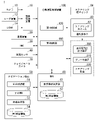
- FIG. 2 is a functional configuration diagram of the first control unit 120 and the second control unit 160.
- the first control unit 120 includes, for example, a recognition unit 130, an action plan generation unit 140, and a mode determination unit 150.
- the first control unit 120 realizes a function by AI (Artificial Intelligence) and a function by a model given in advance in parallel. For example, the function of "recognizing an intersection” is executed in parallel with the recognition of an intersection by deep learning or the like and the recognition based on predetermined conditions (there are signals that can be matched with patterns, road markings, etc.). It may be realized by scoring and comprehensively evaluating. This ensures the reliability of automated driving.
- AI Artificial Intelligence
- the recognition unit 130 recognizes the position, speed, acceleration, and other states of objects around the own vehicle M based on the information input from the camera 10, the radar device 12, and the LIDAR 14 via the object recognition device 16. do.
- the position of the object is recognized as, for example, a position on absolute coordinates with the representative point (center of gravity, center of drive axis, etc.) of the own vehicle M as the origin, and is used for control.
- the position of the object may be represented by a representative point such as the center of gravity or a corner of the object, or may be represented by a region.
- the "state" of an object may include the object's acceleration, jerk, or "behavioral state” (eg, whether it is changing lanes or is about to change lanes).
- the recognition unit 130 recognizes, for example, the lane (traveling lane) in which the own vehicle M is traveling.
- the recognition unit 130 has a road lane marking pattern (for example, an arrangement of a solid line and a broken line) obtained from the second map information 62 and a road lane marking around the own vehicle M recognized from the image captured by the camera 10. By comparing with the pattern of, the driving lane is recognized.
- the recognition unit 130 may recognize the traveling lane by recognizing not only the road marking line but also the running road boundary (road boundary) including the road marking line, the shoulder, the median strip, the guardrail, and the like. .. In this recognition, the position of the own vehicle M acquired from the navigation device 50 and the processing result by the INS may be added.
- the recognition unit 130 also recognizes stop lines, obstacles, red lights, tollhouses, and other road events.
- the recognition unit 130 When recognizing the traveling lane, the recognition unit 130 recognizes the position and posture of the own vehicle M with respect to the traveling lane.
- the recognition unit 130 determines, for example, the deviation of the reference point of the own vehicle M from the center of the lane and the angle formed with respect to the line connecting the center of the lane in the traveling direction of the own vehicle M with respect to the relative position of the own vehicle M with respect to the traveling lane. And may be recognized as a posture. Instead, the recognition unit 130 recognizes the position of the reference point of the own vehicle M with respect to any side end portion (road division line or road boundary) of the traveling lane as the relative position of the own vehicle M with respect to the traveling lane. You may.
- the recognition unit 130 includes an interrupt vehicle recognition unit 132.
- the function of the interrupt vehicle recognition unit 132 will be described later.
- the action plan generation unit 140 travels in the recommended lane determined by the recommended lane determination unit 61, and the own vehicle M automatically (driver) so as to be able to respond to the surrounding conditions of the own vehicle M.
- the target trajectory contains, for example, a speed element.
- the target track is expressed as an arrangement of points (track points) to be reached by the own vehicle M in order.
- the track point is a point to be reached by the own vehicle M for each predetermined mileage (for example, about several [m]) along the road, and separately, for a predetermined sampling time (for example, about 0 comma number [sec]).
- Target velocity and target acceleration are generated as part of the target trajectory.
- the track point may be a position to be reached by the own vehicle M at the sampling time for each predetermined sampling time. In this case, the information of the target velocity and the target acceleration is expressed by the interval of the orbital points.
- the action plan generation unit 140 may set an event for automatic driving when generating a target trajectory.
- Autonomous driving events include constant speed driving events, low speed following driving events, lane change events, branching events, merging events, takeover events, and the like.
- the action plan generation unit 140 generates a target trajectory according to the activated event.
- the action plan generation unit 140 includes an interrupted control unit 142.
- the function of the interrupted control unit 142 will be described later.
- the mode determination unit 150 determines the operation mode of the own vehicle M to be one of a plurality of operation modes in which the task imposed on the driver is different.
- the mode determination unit 150 includes, for example, a driver state determination unit 152 and a mode change processing unit 154. These individual functions will be described later.
- FIG. 3 is a diagram showing an example of the correspondence relationship between the driving mode, the control state of the own vehicle M, and the task.
- the operation mode of the own vehicle M includes, for example, five modes from mode A to mode E.
- the degree of automation of the control state that is, the operation control of the own vehicle M, is highest in mode A, then in the order of mode B, mode C, and mode D, and is lowest in mode E.
- the task imposed on the driver is the mildest in mode A, followed by mode B, mode C, and mode D in that order, and mode E is the most severe.
- the modes D and E are in a control state that is not automatic driving, the automatic driving control device 100 is responsible for ending the control related to automatic driving and shifting to driving support or manual driving.
- mode A and / or mode B is an example of a "second operation mode”
- a part or all of modes C, mode D, and mode E is an example of a "first operation mode”.
- mode A the vehicle is in an automatic driving state, and neither forward monitoring nor gripping of the steering wheel 82 (steering gripping in the figure) is imposed on the driver.
- the driver is required to be in a position to quickly shift to manual operation in response to a request from the system centered on the automatic operation control device 100.
- automated driving as used herein means that both steering and acceleration / deceleration are controlled without depending on the driver's operation.
- the front means the space in the traveling direction of the own vehicle M that is visually recognized through the front windshield.
- Mode A is a condition that the own vehicle M is traveling at a predetermined speed (for example, about 50 [km / h]) or less on a motorway such as an expressway, and there is a vehicle in front to be followed. It is an operation mode that can be executed when is satisfied, and may be referred to as TJP (Traffic Jam Pilot). When this condition is no longer satisfied, the mode determination unit 150 changes the operation mode of the own vehicle M to the mode B.
- TJP Traffic Jam Pilot
- Mode B the driver is in a driving support state, and the driver is tasked with monitoring the front of the own vehicle M (hereinafter referred to as forward monitoring), but is not tasked with gripping the steering wheel 82.
- mode C the driving support state is set, and the driver is tasked with the task of forward monitoring and the task of gripping the steering wheel 82.
- Mode D is a driving mode that requires a certain degree of driving operation by the driver with respect to at least one of steering and acceleration / deceleration of the own vehicle M.
- driving support such as ACC (Adaptive Cruise Control) or LKAS (Lane Keeping Assist System) is provided.
- mode E both steering and acceleration / deceleration are in a state of manual operation that requires a driving operation by the driver.
- mode D and mode E the driver is naturally tasked with monitoring the front of the vehicle M.
- the automatic driving control device 100 executes the lane change according to the driving mode.
- the lane change includes a lane change (1) according to a system request and a lane change (2) according to a driver request.
- the lane change (1) is to change the lane for overtaking and to proceed toward the destination, which is performed when the speed of the vehicle in front is smaller than the standard with respect to the speed of the own vehicle.
- There is a lane change (a lane change due to a change in the recommended lane).
- the lane change (2) changes the lane of the own vehicle M toward the operation direction when the direction indicator is operated by the driver when the conditions related to the speed and the positional relationship with the surrounding vehicles are satisfied. It is something that makes you.
- the automatic driving control device 100 does not execute either the lane change (1) or (2) in the mode A.
- the automatic driving control device 100 executes both the lane change (1) and (2) in modes B and C.
- the driving support device (not shown) does not execute the lane change (1) but executes the lane change (2) in the mode D. In mode E, neither lane change (1) nor (2) is executed.
- the mode determination unit 150 changes the operation mode of the own vehicle M to an operation mode in which the task is more severe when the task related to the determined operation mode (hereinafter referred to as the current operation mode) is not executed by the driver.
- the mode determination unit 150 uses the HMI 30 to promote a shift to manual driving, and if the driver does not respond, controls such that the own vehicle M is brought closer to the road shoulder and gradually stopped to stop automatic driving. After the automatic driving is stopped, the own vehicle is in the mode D or E, and the own vehicle M can be started by the manual operation of the driver.
- stop automatic operation when the driver is in a position where he / she cannot shift to manual driving in response to a request from the system (for example, when he / she continues to look outside the permissible area or when a sign that driving becomes difficult is detected. ).
- the mode determination unit 150 uses the HMI 30 to promote a shift to manual driving, and if the driver does not respond, controls such that the own vehicle M is brought closer to the road shoulder and gradually stopped to stop automatic driving. After the automatic driving is stopped, the own vehicle is in the mode D or E, and the own vehicle M can be started by the manual operation of the driver.
- stop automatic operation the same applies to "stop automatic operation”.
- the mode determination unit 150 urges the driver to monitor the front using the HMI 30, and if the driver does not respond, the vehicle M is brought to the shoulder and gradually stopped. , Stop automatic operation, and so on. If the driver is not monitoring the front in mode C, or is not gripping the steering wheel 82, the mode determination unit 150 uses the HMI 30 to give the driver forward monitoring and / or grip the steering wheel 82. If the driver does not respond, the vehicle M is brought closer to the road shoulder and gradually stopped, and automatic driving is stopped.
- the driver state determination unit 152 monitors the driver's state for the above mode change, and determines whether or not the driver's state is in a state corresponding to the task. For example, the driver state determination unit 152 analyzes the image captured by the driver monitor camera 70 and performs posture estimation processing, and whether or not the driver is in a position where he / she cannot shift to manual driving in response to a request from the system. To judge. Further, the driver state determination unit 152 analyzes the image captured by the driver monitor camera 70 and performs line-of-sight estimation processing to determine whether or not the driver is monitoring the front.
- the mode change processing unit 154 performs various processes for changing the mode. For example, the mode change processing unit 154 instructs the action plan generation unit 140 to generate a target trajectory for shoulder stop, gives an operation instruction to a driving support device (not shown), and gives an action to the driver. HMI30 is controlled to encourage.
- the second control unit 160 sets the traveling driving force output device 200, the brake device 210, and the steering device 220 so that the own vehicle M passes the target trajectory generated by the action plan generation unit 140 at the scheduled time. Control.
- the second control unit 160 includes, for example, an acquisition unit 162, a speed control unit 164, and a steering control unit 166.
- the acquisition unit 162 acquires the information of the target trajectory (orbit point) generated by the action plan generation unit 140 and stores it in a memory (not shown).
- the speed control unit 164 controls the traveling driving force output device 200 or the brake device 210 based on the speed element associated with the target trajectory stored in the memory.
- the steering control unit 166 controls the steering device 220 according to the degree of bending of the target trajectory stored in the memory.
- the processing of the speed control unit 164 and the steering control unit 166 is realized by, for example, a combination of feedforward control and feedback control.
- the steering control unit 166 executes a combination of feedforward control according to the curvature of the road in front of the own vehicle M and feedback control based on the deviation from the target track.
- the traveling driving force output device 200 outputs the traveling driving force (torque) for the vehicle to travel to the drive wheels.
- the traveling driving force output device 200 includes, for example, a combination of an internal combustion engine, an electric motor, a transmission, and the like, and an ECU (Electronic Control Unit) that controls them.
- the ECU controls the above configuration according to the information input from the second control unit 160 or the information input from the operation controller 80.
- the brake device 210 includes, for example, a brake caliper, a cylinder that transmits hydraulic pressure to the brake caliper, an electric motor that generates hydraulic pressure in the cylinder, and a brake ECU.
- the brake ECU controls the electric motor according to the information input from the second control unit 160 or the information input from the operation controller 80 so that the brake torque corresponding to the braking operation is output to each wheel.
- the brake device 210 may include a mechanism for transmitting the hydraulic pressure generated by the operation of the brake pedal included in the operation operator 80 to the cylinder via the master cylinder as a backup.
- the brake device 210 is not limited to the configuration described above, and is an electronically controlled hydraulic brake device that controls the actuator according to the information input from the second control unit 160 to transmit the hydraulic pressure of the master cylinder to the cylinder. May be good.
- the steering device 220 includes, for example, a steering ECU and an electric motor.
- the electric motor for example, exerts a force on the rack and pinion mechanism to change the direction of the steering wheel.
- the steering ECU drives the electric motor according to the information input from the second control unit 160 or the information input from the operation controller 80, and changes the direction of the steering wheel.
- the interrupt vehicle recognition unit 132 recognizes an interrupt vehicle that is a vehicle that interrupts the track on which the own vehicle M is traveling.
- the track is, for example, a lane, but may mean a track determined by the presence of a shoulder or the like on a road without a road division line, or a track virtually assumed in a section in front of a tollhouse. May be good.
- the lane is assumed to be a lane, and the lane in which the own vehicle M is traveling is referred to as the own lane.
- the scenes where the interrupting vehicle interrupts the own lane include the scene where the own vehicle M is traveling on the main lane and the interrupting vehicle is traveling on the confluence where the interrupting vehicle joins the main lane (merging scene), and the road with multiple lanes on each side.
- the interrupting vehicle recognition unit 132 is within the first reference range A1 with respect to the own vehicle M in the merging flow path merging with the own lane. Recognize other vehicles in the area as interrupting vehicles.
- FIG. 4 is a diagram showing how an interrupting vehicle is recognized in a merging scene.
- L1 and L2 are the main lines
- L3 is the junction
- EP is the end point of the junction
- DM is the traveling direction of the own vehicle M
- IM is another vehicle recognized as an interrupt vehicle
- A1 is the first reference range.
- the end point EP is a end point of a section in which the interrupting vehicle IM can interrupt the lane in which the own vehicle M is traveling.
- FIG. 5 is a diagram showing how an interrupting vehicle is recognized in a lane change scene.
- the interrupting vehicle recognition unit 132 interrupts another vehicle within the second reference range A2 based on the operating state of the direction indicator Wk, the lateral movement amount ⁇ Y IM , and its change. Decide whether to recognize it as a vehicle.
- Various methods can be considered for the processing related to this determination, and no particular example is omitted.
- the interrupted control unit 142 determines whether to insert the interrupted vehicle IM in front of or behind the own vehicle M. For example, the interrupted control unit 142 inserts the interrupted vehicle IM in front of the own vehicle M based on the difference between the speed of the own vehicle M and the speed of the interrupted vehicle IM, the front-rear relationship of the predicted position at a predetermined time in the future, and the like. , Decide if you want to put it in the back.
- the interrupted control unit 142 performs deceleration control for inserting the interrupted vehicle IM in front of the own vehicle M in principle.
- the interrupted control unit 142 performs deceleration control when the interrupted vehicle IM is inserted in front of the own vehicle M when the conditions such as the speed of the interrupted vehicle IM being sufficiently higher than the speed of the own vehicle M are satisfied. It may be determined that the interrupt vehicle IM is not present, or that deceleration control is always performed when the interrupt vehicle IM is inserted in front of the own vehicle M.
- the interrupted control unit 142 calculates the deceleration required so that the relationship between the interrupted vehicle IM and the own vehicle M at the end point EP becomes suitable, and reflects it in the speed element of the target trajectory.
- the mode change processing unit 154 of the mode determination unit 150 limits the execution of mode A and / or mode B when the interrupt vehicle IM is recognized and a predetermined condition is satisfied. “Restricting the implementation of mode A and / or mode B” means, for example, changing the operation mode to any of modes C to E. When changing the operation mode from mode A or B to mode D or E, mode C may be sandwiched between them. In this case, if the driver does not grip the steering wheel 82 during the period of mode C, the action plan generation unit 140 temporarily stops the own vehicle on the shoulder or the like, and then changes the driving mode to mode D or E. You may.
- the predetermined condition is, for example, that any of the following conditions (1) to (5) is satisfied.
- the conditions (1) to (4) are conditions for determining whether or not the result of the deceleration control for inserting the interrupting vehicle IM in front of the own vehicle M becomes excessive.
- the condition (5) is a condition for determining whether or not the vehicle is difficult to control by automatic driving or advanced driving support. If any of these is true, it is highly probable that it will be difficult to control the vehicle when interrupted by automatic driving or advanced driving support. Therefore, the mode change processing unit 154 may perform mode A and / or mode B. Restrict the implementation of.
- the condition (1) is that the magnitude of deceleration by deceleration control (maximum deceleration) is equal to or greater than the reference deceleration Gr, and the degree of proximity between the interrupting vehicle IM and the own vehicle M at the end point EP is the first reference degree. Is higher than.
- the mode change processing unit 154 refers to, for example, the velocity element of the target trajectory, and determines whether or not the maximum deceleration is equal to or greater than the reference deceleration Gr. Alternatively, the mode change processing unit 154 may acquire a control schedule from the speed control unit 164 and determine whether or not the maximum deceleration becomes the reference deceleration Gr or more.
- the reference deceleration Gr is, for example, a value of about 0.2 to 0.3 [g].
- the degree of approach is higher than the first reference degree means that, for example, the positions of the own vehicle M and the interrupting vehicle IM overlap at the end point EP, and the speed of the own vehicle M at that time is the third reference speed V3 or less.
- the speed of the own vehicle M at the end point EP is larger than the third reference speed V3, but the distance D in front of the own vehicle M and the interrupting vehicle IM at the end point EP is the third reference vehicle distance.
- One of the following is satisfied that the distance is less than D3 and the rear vehicle distance Dr between the own vehicle M and the interrupting vehicle IM at the end point EP is predicted to be less than the fourth reference vehicle distance D4.
- FIG. 6 is a diagram for explaining the inter-vehicle distance D at the terminal point EP.
- the front inter-vehicle distance D is the distance between the front end portion Mf of the own vehicle M and the rear end portion IMr of the interrupting vehicle IM.
- the rear inter-vehicle distance Dr is the distance between the rear end portion of the own vehicle M and the front end portion of the interrupting vehicle IM.
- the mode change processing unit 154 may make the above determination using the third reference vehicle-to-vehicle distance D3 and the fourth reference vehicle-to-vehicle distance D4, which are fixed values of several to several tens [m], or the speed V of the own vehicle M.
- the third reference vehicle-to-vehicle distance D3 and the fourth reference vehicle-to-vehicle distance D4 may be dynamically changed based on M.
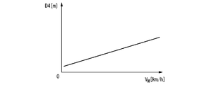
- FIG. 7 is a diagram for explaining processing characteristics when determining the third reference inter-vehicle distance D3 based on the speed VM of the own vehicle M.
- the mode change processing unit 154 may increase the third reference inter-vehicle distance D3 as the speed VM of the own vehicle M increases.
- the mode change processing unit 154 may increase the fourth reference inter-vehicle distance D4 as the speed VM of the own vehicle M increases.
- the speed VM of the own vehicle may be estimated by the action plan generation unit 140 based on the detected value of the wheel speed sensor.
- the scene in which the condition (1) is satisfied is a scene in which the deceleration control causes (predicts or occurs) deceleration to the extent that the occupant of the own vehicle M feels uncomfortable.
- the distance D in front of the own vehicle M and the interrupting vehicle IM at the terminal point EP is less than the third reference vehicle-to-vehicle distance D3, and the rear-vehicle distance Dr between the own vehicle M and the interrupting vehicle IM at the terminal point EP is the fourth reference. If the condition that "the inter-vehicle distance is less than D4" is not satisfied, the own vehicle M and the interrupting vehicle IM are sufficiently separated at the terminal point EP. In this case, the mode change processing unit 154 does not limit the execution of mode A and / or mode B, and the interrupted control unit 142 does not perform deceleration control for inserting the interrupted vehicle IM forward, and the own vehicle as it is. Let M pass the terminal point EP.
- the condition (2) is that the elapsed time from the start of the deceleration control is the first reference time T1 or more, and the degree of expansion of the inter-vehicle distance D between the own vehicle M and the interrupting vehicle IM is lower than the second reference degree. That is.
- the first reference time T1 is, for example, a time of about several [sec].
- the degree of spread of the inter-vehicle distance D is lower than the second reference degree means that, for example, the inter-vehicle distance D is equal to or less than the fifth reference inter-vehicle distance D5, and the inter-vehicle distance D is the inter-vehicle distance in the past third reference time T3.
- the amount of increase in the inter-vehicle distance after subtracting the average value E (D) of the distance is not positive during the fourth reference time T4.
- the third reference time T3 is, for example, a time of 1 [sec] or less.
- the fourth reference time T4 is, for example, a time similar to that of the first reference time T1.
- the mode change processing unit 154 may make the above determination using the fifth reference inter-vehicle distance D5, which is a fixed value of several to several tens [m], or the fourth reference based on the speed VM of the own vehicle M.
- the inter-vehicle distance D4 may be dynamically changed.
- FIG. 9 is a diagram for explaining processing characteristics when determining the fifth reference inter-vehicle distance D5 based on the speed VM of the own vehicle M.
- the mode change processing unit 154 may increase the fifth reference inter-vehicle distance D5 as the speed VM of the own vehicle M increases.
- the scene in which the condition (2) is satisfied is a scene in which the distance between the own vehicle M and the preceding vehicle FM is difficult to open even though the deceleration control is performed.
- the automatic driving control device 100 can suppress the confusion in the traffic phase.
- the condition (3) is that both the speed VM of the own vehicle M and the speed VIM of the interrupting vehicle IM are equal to or less than the first reference speed V1, and the own vehicle M and the previous run in front of the own vehicle M in the own lane.
- the state in which the inter-vehicle distance DFM with the vehicle FM is equal to or greater than the first reference inter-vehicle distance D1 is continued for the second reference time T2 or more.
- the first reference speed V1 is, for example, a speed of less than ten [km / h].
- the first reference vehicle-to-vehicle distance D1 is, for example, a distance of several to a dozen [m].
- the second reference time T2 is, for example, a time of about several [sec].
- the scene in which the condition (3) is satisfied is a scene in which the own vehicle M and the interrupting vehicle IM are traveling at a low speed, and the distance between the own vehicle M and the preceding vehicle FM is difficult to open.
- the automatic driving control device 100 can suppress the confusion in the traffic phase.
- the condition (4) is that the speed VM of the own vehicle M has decreased by the second reference speed V2 or more since the deceleration control was started.
- the second reference speed V2 is, for example, a speed of about 20 to 60 [km / h].
- the condition (4) is satisfied in a situation where the interrupting vehicle IM is not in a state suitable for entering the own lane even though the deceleration control is performed.
- the automatic driving control device 100 can suppress the confusion in the traffic phase.
- the condition (5) is that the speed VM of the own vehicle M is the third reference speed V3 or less, and the inter-vehicle distance D # with the interrupting vehicle IM is less than the second reference inter-vehicle distance D2 behind the interrupting vehicle IM.
- a vehicle hereinafter referred to as a second interrupting vehicle IM2 exists, and the front end portion IM2f of the second interrupting vehicle IM2 is in front of a point rearward by a reference distance Lr from the front end portion Mf of the own vehicle M. ..
- FIG. 10 is a diagram for explaining the condition (5).
- the third reference speed V3 is, for example, a speed of about several tens [km / h].
- the second reference vehicle-to-vehicle distance D2 is, for example, a distance of about several [m] to more than ten [m].
- the reference distance Lr is, for example, a distance of about several [m].
- the scene where the condition (5) is satisfied is a scene in which it is highly probable that it will be difficult to control the vehicle by automatic driving or advanced driving support because both the interrupting vehicle IM and the second interrupting vehicle IM2 must be monitored.
- the automatic driving control device 100 can suppress the confusion in the traffic phase.
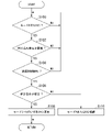
- FIG. 11 is a flowchart showing an example of the flow of processing executed by the mode change processing unit 154.
- the mode change processing unit 154 determines whether or not the driving mode of the own vehicle M is mode A or B (step S100). If it is determined that the operation mode of the own vehicle M is not mode A or B, the process of step S100 is repeatedly executed.
- the mode change processing unit 154 determines whether or not the interrupt vehicle recognition unit 132 has recognized the interrupt vehicle IM (step S102). If it is determined that the interrupt vehicle recognition unit 132 does not recognize the interrupt vehicle, the process is returned to step S100.
- step S104 the mode change processing unit 154 has started deceleration control for the interrupted vehicle IM to be placed in front of the own vehicle M by the interrupted control unit 142. It is determined whether or not (step S104). If it is not determined that the interrupted control unit 142 has started the deceleration control, the process is returned to step S100. The process of step S104 is omitted, and if a positive determination result is obtained in step S102, the process may proceed to step S106.
- the mode change processing unit 154 determines whether or not the predetermined condition is satisfied (step S106). When the predetermined condition is satisfied, the mode change processing unit 154 changes the operation mode of the own vehicle M to any of modes C to E (step S108), and when the predetermined condition is not satisfied, the mode change processing unit 154 changes the mode A or B. Continue (step S110).
- the mode change processing unit 154 limits the implementation of modes A and / or B when the interrupt vehicle recognition unit 132 recognizes the interrupt vehicle IM and a predetermined condition is satisfied. Therefore, appropriate control can be performed according to the situation at the time of being interrupted.
- a storage device that stores the program and With a hardware processor, When the hardware processor executes the program, Recognize the surrounding situation of the vehicle and It controls the steering and acceleration / deceleration of the vehicle without depending on the operation of the driver of the vehicle.
- the driving mode of the vehicle is determined to be one of a plurality of driving modes including a first driving mode and a second driving mode, and the second driving mode is the task assigned to the driver.
- the operation mode is lighter than that of the first operation mode, and at least a part of the plurality of operation modes including the second operation mode is controlled by the operation control unit, and the determined operation is performed.
- the driving mode of the vehicle is changed to a driving mode in which the task is more severe.
- the interrupting vehicle which is a vehicle interrupting the lane in which the vehicle is traveling is recognized.
- the implementation of the second driving mode is restricted.
- a vehicle control unit configured as such.
Landscapes
- Engineering & Computer Science (AREA)
- Automation & Control Theory (AREA)
- Transportation (AREA)
- Mechanical Engineering (AREA)
- Human Computer Interaction (AREA)
- Traffic Control Systems (AREA)
- Control Of Driving Devices And Active Controlling Of Vehicle (AREA)
Abstract
Priority Applications (3)
| Application Number | Priority Date | Filing Date | Title |
|---|---|---|---|
| CN202080107812.XA CN116568580A (zh) | 2020-12-28 | 2020-12-28 | 车辆控制装置、车辆控制方法及程序 |
| PCT/JP2020/049092 WO2022144954A1 (fr) | 2020-12-28 | 2020-12-28 | Dispositif de commande de véhicule, procédé de commande de véhicule et programme |
| JP2022527923A JP7329142B2 (ja) | 2020-12-28 | 2020-12-28 | 車両制御装置 |
Applications Claiming Priority (1)
| Application Number | Priority Date | Filing Date | Title |
|---|---|---|---|
| PCT/JP2020/049092 WO2022144954A1 (fr) | 2020-12-28 | 2020-12-28 | Dispositif de commande de véhicule, procédé de commande de véhicule et programme |
Publications (1)
| Publication Number | Publication Date |
|---|---|
| WO2022144954A1 true WO2022144954A1 (fr) | 2022-07-07 |
Family
ID=82260347
Family Applications (1)
| Application Number | Title | Priority Date | Filing Date |
|---|---|---|---|
| PCT/JP2020/049092 WO2022144954A1 (fr) | 2020-12-28 | 2020-12-28 | Dispositif de commande de véhicule, procédé de commande de véhicule et programme |
Country Status (3)
| Country | Link |
|---|---|
| JP (1) | JP7329142B2 (fr) |
| CN (1) | CN116568580A (fr) |
| WO (1) | WO2022144954A1 (fr) |
Citations (3)
| Publication number | Priority date | Publication date | Assignee | Title |
|---|---|---|---|---|
| JP2020128165A (ja) * | 2019-02-08 | 2020-08-27 | スズキ株式会社 | 車両の走行制御装置 |
| JP2020157985A (ja) * | 2019-03-27 | 2020-10-01 | スズキ株式会社 | 車両の走行制御装置 |
| JP2020163908A (ja) * | 2019-03-28 | 2020-10-08 | 本田技研工業株式会社 | 車両制御装置、車両制御方法、及びプログラム |
-
2020
- 2020-12-28 CN CN202080107812.XA patent/CN116568580A/zh active Pending
- 2020-12-28 JP JP2022527923A patent/JP7329142B2/ja active Active
- 2020-12-28 WO PCT/JP2020/049092 patent/WO2022144954A1/fr active Application Filing
Patent Citations (3)
| Publication number | Priority date | Publication date | Assignee | Title |
|---|---|---|---|---|
| JP2020128165A (ja) * | 2019-02-08 | 2020-08-27 | スズキ株式会社 | 車両の走行制御装置 |
| JP2020157985A (ja) * | 2019-03-27 | 2020-10-01 | スズキ株式会社 | 車両の走行制御装置 |
| JP2020163908A (ja) * | 2019-03-28 | 2020-10-08 | 本田技研工業株式会社 | 車両制御装置、車両制御方法、及びプログラム |
Also Published As
| Publication number | Publication date |
|---|---|
| CN116568580A (zh) | 2023-08-08 |
| JP7329142B2 (ja) | 2023-08-17 |
| JPWO2022144954A1 (fr) | 2022-07-07 |
Similar Documents
| Publication | Publication Date | Title |
|---|---|---|
| JP6942236B1 (ja) | 車両制御装置、車両制御方法、およびプログラム | |
| JP2022103505A (ja) | 車両制御装置、車両制御方法、およびプログラム | |
| JP7194224B2 (ja) | 車両制御装置、車両制御方法、およびプログラム | |
| JP7470157B2 (ja) | 車両制御装置、車両制御方法、およびプログラム | |
| JP7308880B2 (ja) | 車両制御装置、車両制御方法、およびプログラム | |
| JP2023030147A (ja) | 車両制御装置、車両制御方法、およびプログラム | |
| US11628744B2 (en) | Vehicle control device, vehicle control method, and storage medium | |
| JP7092955B1 (ja) | 車両制御装置、車両制御方法、およびプログラム | |
| JP7046289B1 (ja) | 車両制御装置、車両システム、車両制御方法、およびプログラム | |
| WO2022144954A1 (fr) | Dispositif de commande de véhicule, procédé de commande de véhicule et programme | |
| JP2022096236A (ja) | 車両制御装置、車両制御方法、及びプログラム | |
| WO2022144970A1 (fr) | Dispositif de commande de véhicule, procédé de commande de véhicule, et programme | |
| JP7075550B1 (ja) | 車両制御装置、車両制御方法、およびプログラム | |
| WO2022144974A1 (fr) | Dispositif de commande de véhicule, procédé de commande de véhicule et programme | |
| WO2022144976A1 (fr) | Dispositif de commande de véhicule, procédé de commande de véhicule, et programme | |
| JP7048832B1 (ja) | 車両制御装置、車両制御方法、およびプログラム | |
| WO2022144950A1 (fr) | Dispositif de commande de véhicule, procédé de commande de véhicule et programme | |
| JP7256168B2 (ja) | 車両制御装置、車両制御方法、及びプログラム | |
| JP7201657B2 (ja) | 車両制御装置、車両制御方法、およびプログラム | |
| JP7425132B1 (ja) | 車両制御装置、車両制御方法、およびプログラム | |
| WO2022144958A1 (fr) | Dispositif de commande de véhicule, procédé de commande de véhicule et programme | |
| JP7112479B2 (ja) | 車両制御装置、車両制御方法、およびプログラム | |
| JP7186210B2 (ja) | 車両制御装置、車両制御方法、およびプログラム | |
| JP2022152697A (ja) | 車両制御装置、車両制御方法、及びプログラム | |
| JP2022155838A (ja) | 車両制御装置、経路生成装置、車両制御方法、経路生成方法、およびプログラム |
Legal Events
| Date | Code | Title | Description |
|---|---|---|---|
| ENP | Entry into the national phase |
Ref document number: 2022527923 Country of ref document: JP Kind code of ref document: A |
|
| 121 | Ep: the epo has been informed by wipo that ep was designated in this application |
Ref document number: 20967967 Country of ref document: EP Kind code of ref document: A1 |
|
| WWE | Wipo information: entry into national phase |
Ref document number: 202080107812.X Country of ref document: CN |
|
| WWE | Wipo information: entry into national phase |
Ref document number: 18268618 Country of ref document: US |
|
| NENP | Non-entry into the national phase |
Ref country code: DE |
|
| 122 | Ep: pct application non-entry in european phase |
Ref document number: 20967967 Country of ref document: EP Kind code of ref document: A1 |