WO2022138704A1 - 通信用電線 - Google Patents
通信用電線 Download PDFInfo
- Publication number
- WO2022138704A1 WO2022138704A1 PCT/JP2021/047520 JP2021047520W WO2022138704A1 WO 2022138704 A1 WO2022138704 A1 WO 2022138704A1 JP 2021047520 W JP2021047520 W JP 2021047520W WO 2022138704 A1 WO2022138704 A1 WO 2022138704A1
- Authority
- WO
- WIPO (PCT)
- Prior art keywords
- sheath layer
- layer
- melting point
- magnetic
- magnetic sheath
- Prior art date
- Legal status (The legal status is an assumption and is not a legal conclusion. Google has not performed a legal analysis and makes no representation as to the accuracy of the status listed.)
- Ceased
Links
Images

Classifications
-
- H—ELECTRICITY
- H01—ELECTRIC ELEMENTS
- H01B—CABLES; CONDUCTORS; INSULATORS; SELECTION OF MATERIALS FOR THEIR CONDUCTIVE, INSULATING OR DIELECTRIC PROPERTIES
- H01B11/00—Communication cables or conductors
- H01B11/18—Coaxial cables; Analogous cables having more than one inner conductor within a common outer conductor
- H01B11/1869—Construction of the layers on the outer side of the outer conductor
-
- H—ELECTRICITY
- H01—ELECTRIC ELEMENTS
- H01B—CABLES; CONDUCTORS; INSULATORS; SELECTION OF MATERIALS FOR THEIR CONDUCTIVE, INSULATING OR DIELECTRIC PROPERTIES
- H01B11/00—Communication cables or conductors
- H01B11/02—Cables with twisted pairs or quads
- H01B11/06—Cables with twisted pairs or quads with means for reducing effects of electromagnetic or electrostatic disturbances, e.g. screens
- H01B11/10—Screens specially adapted for reducing interference from external sources
- H01B11/1058—Screens specially adapted for reducing interference from external sources using a coating, e.g. a loaded polymer, ink or print
- H01B11/1083—Screens specially adapted for reducing interference from external sources using a coating, e.g. a loaded polymer, ink or print the coating containing magnetic material
-
- H—ELECTRICITY
- H01—ELECTRIC ELEMENTS
- H01B—CABLES; CONDUCTORS; INSULATORS; SELECTION OF MATERIALS FOR THEIR CONDUCTIVE, INSULATING OR DIELECTRIC PROPERTIES
- H01B11/00—Communication cables or conductors
- H01B11/18—Coaxial cables; Analogous cables having more than one inner conductor within a common outer conductor
- H01B11/1808—Construction of the conductors
- H01B11/1813—Co-axial cables with at least one braided conductor
-
- H—ELECTRICITY
- H01—ELECTRIC ELEMENTS
- H01B—CABLES; CONDUCTORS; INSULATORS; SELECTION OF MATERIALS FOR THEIR CONDUCTIVE, INSULATING OR DIELECTRIC PROPERTIES
- H01B11/00—Communication cables or conductors
- H01B11/18—Coaxial cables; Analogous cables having more than one inner conductor within a common outer conductor
- H01B11/1808—Construction of the conductors
- H01B11/1817—Co-axial cables with at least one metal deposit conductor
-
- H—ELECTRICITY
- H01—ELECTRIC ELEMENTS
- H01B—CABLES; CONDUCTORS; INSULATORS; SELECTION OF MATERIALS FOR THEIR CONDUCTIVE, INSULATING OR DIELECTRIC PROPERTIES
- H01B11/00—Communication cables or conductors
- H01B11/18—Coaxial cables; Analogous cables having more than one inner conductor within a common outer conductor
- H01B11/1878—Special measures in order to improve the flexibility
-
- H—ELECTRICITY
- H01—ELECTRIC ELEMENTS
- H01B—CABLES; CONDUCTORS; INSULATORS; SELECTION OF MATERIALS FOR THEIR CONDUCTIVE, INSULATING OR DIELECTRIC PROPERTIES
- H01B11/00—Communication cables or conductors
- H01B11/18—Coaxial cables; Analogous cables having more than one inner conductor within a common outer conductor
- H01B11/1895—Particular features or applications
-
- H—ELECTRICITY
- H01—ELECTRIC ELEMENTS
- H01B—CABLES; CONDUCTORS; INSULATORS; SELECTION OF MATERIALS FOR THEIR CONDUCTIVE, INSULATING OR DIELECTRIC PROPERTIES
- H01B7/00—Insulated conductors or cables characterised by their form
- H01B7/17—Protection against damage caused by external factors, e.g. sheaths or armouring
- H01B7/29—Protection against damage caused by extremes of temperature or by flame
- H01B7/292—Protection against damage caused by extremes of temperature or by flame using material resistant to heat
Definitions
- This disclosure relates to communication wires.
- a metal foil or a metal braided layer provided as an external conductor on the outer periphery of the signal line plays the role of a noise shield that reduces noise intrusion from the outside and emission of noise to the outside. Fulfill.
- a metal foil or a metal braided layer is placed on the outer periphery of the signal line. The provision alone may be insufficient in reducing the influence of noise.
- a member containing a magnetic material such as a ferrite core may be attached to the outer periphery of the coaxial electric wire.
- a shield body made of a metal material such as a metal foil or a metal braid is provided, and a sheath layer containing a magnetic material is further provided on the outside thereof to provide a communication electric wire. May be configured.
- a member such as a ferrite core is arranged on the outer peripheral portion for the purpose of reducing interference with an external electromagnetic wave, it is necessary to increase the mass and arrange the communication electric wire. The increase in space becomes noticeable. In fields where weight reduction and space saving of electric wires used are important, such as automobiles, it is not realistic to adopt a member such as a ferrite core as a countermeasure against electromagnetic waves to a communication electric wire.
- a shield layer containing a magnetic material is integrally provided on the outer periphery of the coaxial electric wire as in the form disclosed in Patent Documents 1 and 2, it is lighter and more space-saving than the case of using a ferrite core. Easy to increase.
- the sheath layer containing this kind of magnetic material tends to have low flexibility because it contains a large amount of magnetic material so that electromagnetic waves can be sufficiently shielded. If a coaxial wire having a sheath layer with low flexibility is continuously used in an environment that is frequently bent or vibrated, such as in an automobile, a large load may be applied to the inner metal foil.
- FIG. 3 shows a state in which a conventional general coaxial type communication wire 1'is bent along the axial direction.
- the communication wire 1' has a metal foil 5 and a braided layer 6 in this order on the outside of a core wire 4 provided with an insulating layer 3 on the outer periphery of the conductor 2, and further contains a magnetic material on the outer periphery of the braided layer 6 magnetically. It has a sheath layer 7.
- the metal foil 5 and the braided layer 6 follow the bending of the core wire 4, but the magnetic sheath layer 7 is difficult to bend due to its low flexibility, so that the core wire 4 Can't keep up with the bending of. Therefore, as shown by an ellipse in the figure, the bent braided layer 6 comes into contact with the inner peripheral surface of the magnetic sheath layer 7 at a small area contact portion A'. Then, in the contact portion A'of this small area, the metal foil 5 is sandwiched between the braided layer 6 and the core wire 4, and a large load accompanied by compression or friction is applied to the metal foil 5.
- the magnetic sheath layer 7 that does not easily follow the bending is arranged on the outer periphery of the metal foil 5, it is sandwiched between the core wire 4 and the magnetic sheath layer 7 when the communication electric wire 1'is bent.
- the application of the load becomes particularly serious.
- damage such as breakage and cracks is likely to occur in the metal foil 5. Damage to the metal foil 5 leads to a decrease in the noise shielding performance of the communication wire 1'.
- Avoiding damage to the metal leaf due to the presence of the inflexible magnetic sheath layer as described above is important for maintaining noise shielding performance in coaxial communication wires even in environments subject to bending and vibration. Is. Furthermore, when the communication wire is used in an environment that tends to be hot, such as in an automobile, even if it is placed in a high temperature environment, the metal leaf may be damaged due to the presence of the magnetic sheath layer. It is desired that high noise shielding performance can be maintained.
- the communication electric wire according to the present disclosure contains a conductor, an organic polymer, an insulating layer covering the outer periphery of the conductor, a metal foil covering the outer periphery of the insulating layer, an organic polymer, and a powdery magnetic material.
- the mass ratio occupied by the low melting point polymer among the organic polymer components constituting each layer is defined as the low melting point component ratio, and the low melting point component ratio is higher than that of the insulating layer in the magnetic sheath layer. Is also getting bigger.
- the communication electric wire according to the present disclosure is less likely to be damaged during bending due to the influence of the sheath layer containing the magnetic material provided on the outer periphery of the metal foil.
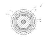
- FIG. 1 is a cross-sectional view cut perpendicular to the axial direction showing the configuration of a communication electric wire according to an embodiment of the present disclosure.
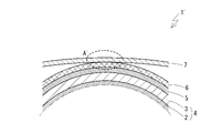
- FIG. 2 is a cross-sectional view showing a state in which a communication wire according to an embodiment of the present disclosure having a highly flexible magnetic sheath layer is bent, in a cross section along an axial direction. In FIG. 2 and FIG. 3 below, only the region outside the central portion of the conductor is shown. Moreover, the outer sheath layer is omitted.
- FIG. 3 is a cross-sectional view showing a state in which a conventional general communication wire having a magnetic sheath layer having a low flexibility is bent, in a cross section along the axial direction.
- the communication electric wire according to the present disclosure contains a conductor, an organic polymer, an insulating layer covering the outer periphery of the conductor, a metal foil covering the outer periphery of the insulating layer, an organic polymer, and a powdery magnetic material.
- the mass ratio occupied by the low melting point polymer among the organic polymer components constituting each layer is defined as the low melting point component ratio, and the low melting point component ratio is higher than that of the insulating layer in the magnetic sheath layer. Is also getting bigger.
- the magnetic sheath layer provided on the outer side of the metal foil has a lower tensile elastic modulus than the inner insulating layer. That is, the magnetic sheath layer has high flexibility. Therefore, when the communication wire is bent, the magnetic sheath layer follows the bending well and comes into contact with a member such as the magnetic sheath layer or optionally a braided layer provided inside the magnetic sheath layer in a large area. maintain. As a result, a large load is less likely to be concentrated and applied from the magnetic sheath layer to a specific portion of the metal foil, and damage to the metal foil is less likely to occur even after bending.
- the ratio of the low melting point component is larger in the magnetic sheath layer than in the insulating layer. That is, the magnetic sheath layer contains more low melting point polymer having a melting point of 100 ° C. or lower than the insulating layer. Therefore, when the communication wire is exposed to a high temperature, the magnetic sheath layer starts softening from a lower temperature than the insulating layer. As a result, even at a high temperature, the magnetic sheath layer is more likely to maintain a state of being more flexible than the insulating layer, and the above-mentioned suppression of damage to the metal foil due to the magnetic sheath layer following bending. However, it is also achieved in a high temperature environment. Therefore, the communication electric wire can be suitably used as a means for maintaining high electromagnetic wave shielding performance even in an environment where vibration or bending is applied and the temperature becomes high, such as in an automobile.
- the communication electric wire is further configured as a braided body in which a metal wire is knitted, and has a braided layer that covers the outer periphery of the metal foil, and the magnetic sheath layer covers the outer periphery of the braided layer. It is good to have.
- a braided layer made of a metal wire on the outer periphery of the metal foil, the load applied to the metal foil when the communication electric wire is bent tends to be large, but this is the embodiment of the present disclosure.
- the magnetic sheath layer follows the bending of the communication wire well, and the contact area between the metal foil and the braided layer is maintained large. Therefore, the magnetic sheath layer is applied to the metal foil via the braided layer. The load to be applied is effectively reduced.
- the content of the low melting point polymer in the magnetic sheath layer is smaller than the content of the high melting point polymer having a melting point of more than 100 ° C.
- the ratio of the low melting point component is preferably 15% or more and 45% or less in the magnetic sheath layer, and 10% or less in the insulating layer. Then, at normal temperature and high temperature, the flexibility of the magnetic sheath layer is increased, and the effect of suppressing damage to the metal foil due to bending of the communication wire is particularly excellent.
- the magnetic sheath layer may contain a copolymer of ethylene and a polar monomer as the low melting point polymer. Such copolymers tend to have a low melting point and high flexibility, as well as a high affinity for magnetic materials. As a result, in the magnetic sheath layer, the flexibility and mechanical strength of the magnetic sheath layer are effectively improved.
- the flexibility evaluated by the three-point bending test is higher than that of the insulating layer in the magnetic sheath layer at both 23 ° C and 150 ° C. This means that the magnetic sheath layer maintains more flexibility than the insulating layer from normal temperature to a high temperature of about 150 ° C. Therefore, in an environment from room temperature to high temperature, when the communication wire is bent, the magnetic sheath layer follows the bending, so that the formation of damage to the metal foil can be effectively suppressed. ..
- the magnetic sheath layer may contain 200 parts by mass or more and 800 parts by mass or less of the magnetic material with respect to 100 parts by mass of the organic polymer component. Then, the magnetic sheath layer exhibits high electromagnetic wave shielding performance and is less likely to impair the flexibility exhibited by the organic polymer component.
- the communication wire may further have an outer sheath layer containing an organic polymer and no magnetic material on the outer periphery of the magnetic sheath layer.
- the outer sooth layer protects the magnetic sheath layer from contact with external objects. Further, the progress of damage such as cracks and cracks generated in the magnetic sheath can be suppressed by the presence of the outer sheath layer.
- the ratio of the low melting point component is larger in the magnetic sheath layer than in the outer sheath layer.
- the magnetic sheath layer tends to have lower flexibility than the outer sheath layer containing no magnetic material because it contains a magnetic material, and the flexibility tends to decrease particularly at high temperatures.
- the magnetic sheath layer has a larger proportion of low melting point components than the outer sheath layer, the magnetic sheath layer maintains high flexibility from room temperature to high temperature, and when the communication wire is bent. In addition, it is possible to effectively suppress the application of a large load from the magnetic sheath layer to the metal foil.
- the magnetic sheath layer may contain an organic polymer having adhesiveness to the outer sheath layer. Then, the presence of the outer sheath layer enhances the effect of suppressing the progress of damage caused in the magnetic sheath layer.
- FIG. 1 shows a cross-sectional view of a communication wire 1 according to an embodiment of the present disclosure, cut perpendicularly in the axial direction.
- the communication electric wire 1 is configured as a coaxial electric wire, and can be suitably used for transmitting a signal in a high frequency range of, for example, 1 GHz or more.
- the communication electric wire 1 includes a core wire 4 having a conductor 2 and an insulating layer 3 covering the outer periphery of the conductor 2. Further, on the outer periphery of the core wire 4, a metal foil 5 and a braided layer 6 configured as a braided body in which a metal strand is knitted are provided as a metal shield layer.
- the metal foil 5 covers the outer periphery of the core wire 4, and further covers the outer periphery of the metal foil 5, so that the braided layer 6 is provided.
- a magnetic sheath layer 7 containing a magnetic material is provided on the outer periphery of the braided layer 6. Further, an outer sheath layer 8 containing no magnetic material is optionally provided on the outer periphery of the magnetic sheath layer 7.
- the magnetic sheath layer 7 and the insulating layer 3 both formed as a layer containing an organic polymer have the following relations 1 and 2 in terms of tensile modulus and composition. It is preferable that the relationship 3 is further satisfied. Relationship 1: The tensile elastic modulus of the magnetic sheath layer 7 is lower than the tensile elastic modulus of the insulating layer 3. -Relationship 2: The ratio of the low melting point component is larger in the magnetic sheath layer 7 than in the insulating layer 3. -Relationship 3: Further, it is preferable that the flexibility evaluated by the three-point bending test is the insulating layer 3 or more in the magnetic sheath layer 7 at both 23 ° C. and 150 ° C.
- the tensile elastic modulus can be evaluated by a tensile test based on JIS K 7161.
- an organic polymer having a melting point of 100 ° C. or lower is defined as a low melting point polymer, and the mass ratio of the low melting point polymer among the organic polymer components constituting each layer (each of the insulating layer 3 and the magnetic sheath layer 7) is defined as the low melting point component. It is a ratio.
- the numerical value when the content of the low melting point polymer is displayed in units of parts by mass with the entire organic polymer component constituting each layer as 100 parts by mass is the ratio of low melting point components in%.
- the 3-point bending test is a test that measures the maximum bending stress when bending is applied to the central part by supporting both ends in the length direction of the sample as a 3-point bending force by a bending characteristic test based on JIS K7171.
- the three-point bending force (unit: N)
- the values measured for the target layer cut out to a length of 80 mm are displayed.
- the magnetic sheath layer 7 and the insulating layer 3 have the above-mentioned relationships 1 and 2, and more preferably the relationship 3 causes the communication wire 1 to be bent in a normal temperature and high temperature environment. At the same time, damage due to the presence of the magnetic sheath layer 7 is less likely to occur in the metal foil 5.
- each component of the communication electric wire 1 will be described in detail.
- the conductor 2 is responsible for transmitting an electric signal.
- various metal materials can be used, but it is preferable to use a copper alloy from the viewpoint of having high conductivity and the like.
- the conductor 2 may be configured as a single wire, but from the viewpoint of increasing flexibility at the time of bending, it is preferable that the conductor 2 is configured as a stranded wire in which a plurality of strands (for example, 7 wires) are twisted together. In this case, after the strands are twisted together, compression molding may be performed to obtain a compression stranded wire.
- the conductor 2 When the conductor 2 is configured as a stranded wire, it may be composed of all the same strands or may include two or more types of strands.
- the diameter of the conductor 2 is not particularly limited.
- As the cross-sectional area of the conductor a range of 0.05 mm 2 or more and 1.0 mm 2 or less can be exemplified.
- the insulating layer 3 insulates the conductor 2 in the core wire 4, and contains an insulating organic polymer.
- the type of the organic polymer is not particularly limited as long as the relationship 1 and 2 are satisfied with the magnetic sheath layer 7, but the olefin polymer such as polyolefin or olefin copolymer and polyvinyl chloride are not particularly limited. Halogen-based polymers such as, various engineering plastics, elastomers, rubbers and the like can be mentioned.
- As the organic polymer only one kind may be used, or two or more kinds may be used in combination by mixing, laminating or the like.
- the organic polymer may be crosslinked or may be foamed.
- the organic polymer constituting the insulating layer 3 it is preferable to use one of the above-listed organic polymers having a low molecular polarity as the organic polymer constituting the insulating layer 3.
- a non-polar organic polymer such as a polyolefin such as polypropylene (PP).
- PP polypropylene
- the polyolefin a homopolyolefin such as homo-PP may be used, or a block polyolefin such as block PP may be used.
- the insulating layer 3 may contain a polar organic polymer such as a modified polyolefin, but the content thereof is preferably 10% or less, more preferably 5% or less, in terms of the mass ratio to the entire organic polymer component. ..
- the insulating layer 3 has a high tensile modulus as compared with the magnetic sheath layer 7, and contains only a small amount of low melting point polymer.
- the ratio of the low melting point component in the insulating layer 3, that is, the ratio of the low melting point polymer having a melting point of 100 ° C. or less is preferably 10% or less, further 5% or less, and other than the small amount of the low melting point polymer.
- the polymer component is preferably a high melting point polymer having a melting point of more than 100 ° C., preferably 150 ° C. or higher.
- the insulating layer 3 does not have to contain the low melting point polymer at all, but from the viewpoint of ensuring a certain degree of flexibility and extrudability, the insulating layer 3 may contain a low melting point polymer having a low melting point component ratio of 1% or more. preferable.
- the low melting point polymer that can be contained in the insulating layer 3 include thermoplastic elastomers such as acid-modified hydrogenated styrene-based thermoplastic elastomers (SEBS), acid-modified polypropylenes, acid-modified polyolefins such as acid-modified polyethylenes, and ethylene-.
- ethylene-based copolymers such as ethyl acrylate copolymer (EEA), ethylene-methyl acrylate copolymer (EMA), and ethylene-vinyl acetate copolymer (EVA) can be exemplified.
- EAA ethyl acrylate copolymer
- EMA ethylene-methyl acrylate copolymer
- EVA ethylene-vinyl acetate copolymer
- the insulating layer 3 may contain an additive as appropriate in addition to the organic polymer.
- the additive include flame retardant agents such as metal hydroxides, copper damage inhibitors, antioxidants such as hindered phenols and sulfurs, and metal oxides such as zinc oxide.
- the insulating layer 3 should not contain an additive made of a magnetic material, such as that contained in the magnetic sheath layer 7.
- the insulating layer 3 may have any tensile elastic modulus as an absolute value as long as the material as a whole has a tensile elastic modulus higher than that of the magnetic sheath layer 7.
- the tensile elastic modulus of the insulating layer 3 is 1600 MPa or more from the viewpoint of avoiding damage to the metal foil 5 due to bending by making it easier to make the tensile elastic modulus relatively low and limiting the bending of the core wire 4 to some extent. Further, it is preferably 1695 MPa or more.
- the tensile elastic modulus of the insulating layer 3 is preferably 2500 MPa or less from the viewpoint of ensuring sufficient flexibility.
- the three-point bending force of the insulating layer 3 makes it easy to satisfy the above relationship 3, and from the viewpoint of limiting the bending of the core wire 4 to some extent at room temperature and room temperature, it is 2.0 N or more at 23 ° C and 0 at 150 ° C. It is good that it is 8.8N or more.
- the three-point bending force of the insulating layer 3 is preferably 3.3 N or less at 23 ° C and 2.0 N or less at 150 ° C. ..
- the thickness of the insulating coating 3 is not particularly limited, but can exemplify a range of 0.1 mm or more and 1.0 mm or less.
- the metal foil 5 is configured as a thin film of a metal material.
- the metal foil 5 shields noise that enters the core wire 4 and noise that is emitted from the core wire 4.
- the type of metal constituting the metal foil 5 is not particularly limited, and copper, copper alloys, aluminum, aluminum alloys, and the like can be exemplified.
- the metal foil 5 may be composed of a single metal species or may be laminated with layers of two or more metal species.
- the metal foil 5 is formed by bonding a metal layer to a substrate such as a polymer film such as polyethylene terephthalate (PET) by vapor deposition, plating, adhesion, or the like. You may.
- the strength of the metal foil 5 is improved due to the contribution of the base material, and damage to the metal foil 5 during bending is less likely to occur.
- the metal foil 5 is composed of an independent metal thin film, the characteristics and composition of the magnetic sheath layer 7 can be applied by applying a load to the metal leaf 5 when the communication wire 1 is bent. By specifying it, the effect of reduction becomes relatively high.
- the metal foil 5 is preferably arranged vertically with respect to the core wire 4. From the viewpoint of enhancing the noise shielding effect, the thickness of the metal foil is preferably 1 ⁇ m or more.
- the metal foil 5 when the communication electric wire 1 is bent, the metal foil 5 follows and is easily bent and deformed, and the effect of suppressing damage to the metal foil 5 by selecting the materials of the insulating layer 3 and the magnetic sheath layer 7 is achieved. From the viewpoint of obtaining a high value, the thickness of the metal foil 5 is preferably 40 ⁇ m or less.
- the braided layer 6 is configured as a braided body in which a plurality of metal strands are woven into each other to form a hollow cylinder.
- the braided layer 6 functions as an outer conductor, and together with the metal foil 5, plays a role of shielding noise invading the core wire 4 and noise emitted from the core wire 4.
- a metal material such as copper, a copper alloy, aluminum, or an aluminum alloy, or a metal material whose surface is plated with tin or the like can be exemplified.
- the metal foil 5 and the braided layer 6 may be a plurality of layers, or another layer may be provided between the metal foil 5 and the braided layer 6 or inside or outside the layers.
- the magnetic sheath layer 7 via the braided layer 6 to the metal foil 5 may occur when the communication electric wire 1 is bent.
- the application of the load is reduced by defining the characteristics and composition of the magnetic sheath layer 7, and from the viewpoint of enhancing the effect, the braided layer 6 and the metal foil 5, and the braided layer 6 and the magnetic sheath layer 7 are separated from each other. It is preferable that the metal is in direct contact with the metal without interposing other members.
- the braided layer 6 is not indispensable for the communication electric wire 1, but the braided layer made of a metal material is provided inside the magnetic sheath layer 7, so that the braided layer 6 is provided for communication as compared with the case where the braided layer 6 is not provided.
- the load applied to the metal foil 5 from the outside becomes large. Therefore, as will be described later, by making the magnetic sheath layer 7 have high flexibility, the effect of reducing the application of the load to the metal foil 5 is greater when the braided layer 6 is provided. Become.
- the magnetic sheath layer 7 covers the outer periphery of the core wire 4 via the metal foil 5 and the braided layer 6.
- the magnetic sheath layer 7 is not bonded to the braided layer 6, and is deformed independently of the braided layer 6 when the communication wire 1 is bent (see FIG. 2).
- the magnetic sheath layer 7 contains a particulate magnetic material and an organic polymer.
- the powder of the magnetic material takes a state of being dispersed in a matrix composed of an organic polymer.
- the magnetic material contained in the magnetic sheath layer 7 is preferably a ferromagnetic material, and more preferably a metal or a metal compound having soft magnetism. Since the magnetic sheath layer 7 contains a magnetic material, particularly a soft magnetic material, an excellent noise shielding effect can be obtained in the communication electric wire 1.
- the phenomenon that the electromagnetic wave from the outside of the communication wire 1 invades the communication wire 1 and becomes noise and affects the signal transmitted through the core wire 4 and the signal transmitted through the core wire 4 It is possible to suppress the phenomenon that the resulting noise is emitted to the outside of the communication wire 1.
- the noise shielding effect is also exhibited by the metal leaf 5 and the braided layer 6, but when the communication wire 1 is used for communication in a high frequency range such as 1 GHz or more, the influence of noise is exerted. It tends to be serious, and by providing the magnetic sheath layer 7 together with the metal foil 5 and the braided layer 6, the influence of noise can be effectively reduced.
- soft magnetic materials showing high noise shielding properties in the high frequency region iron (pure iron or iron containing a small amount of carbon), silicon steel, Fe-Si-Al alloy (Sendust), Fe-Cr-Al-Si alloy and the like
- magnetic stainless steel such as Fe—Cr—Si alloy, Fe—Ni based alloy (permalloy), ferrite and the like.
- Fe—Si—Al alloy or ferrite it is particularly preferable to use Fe—Si—Al alloy or ferrite from the viewpoint of being particularly excellent in noise shielding property.
- the ferrite a Ni—Zn-based one can be particularly preferably used.
- the magnetic material only one kind may be used, or two or more kinds may be used in combination by mixing or the like.
- the content of the magnetic material in the magnetic sheath layer 7 is not particularly limited, but is 200 parts by mass or more, with the total of the organic polymer components being 100 parts by mass from the viewpoint of obtaining a high noise shielding effect. Is preferable. On the other hand, from the viewpoint of ensuring the characteristics exhibited by the organic polymer such as flexibility in the magnetic sheath layer 7, the content thereof is preferably 800 parts by mass or less.
- the type of organic polymer used is not particularly limited as long as the above relationship 1 and relationship 2 are satisfied with the insulating layer 3.
- olefin polymers such as polyolefins and olefin copolymers, halogen polymers such as polyvinyl chloride, various engineering plastics, elastomers, rubbers and the like can be used.
- the organic polymer only one kind may be used, or two or more kinds may be used in combination by mixing, laminating or the like.
- a form in which an organic polymer having a melting point of 100 ° C. or higher and an organic polymer having a melting point of more than 100 ° C. are mixed and used is particularly preferable.
- the organic polymer may be crosslinked or may be foamed.
- the magnetic sheath layer 7 contains at least a larger amount of a low melting point polymer having a melting point of 100 ° C. or lower than that of the insulating layer 3, as described in Relationship 2 above.
- a low melting point polymer contained in the magnetic sheath layer 7 various thermoplastic polymers such as an olefin-based thermoplastic resin and a styrene-based elastomer such as SEBS can be preferably used.
- olefin-based thermoplastic resin examples include polyolefins such as polyethylene, acid-modified polypropylene, acid-modified polyolefins such as acid-modified polyethylene, ethylene-ethyl acrylate copolymer (EEA), and ethylene-methyl acrylate.
- polyolefins such as polyethylene, acid-modified polypropylene, acid-modified polyolefins such as acid-modified polyethylene, ethylene-ethyl acrylate copolymer (EEA), and ethylene-methyl acrylate.
- Polymers of ethylene and polar monomers such as polymers (EMA), ethylene-methylmethacrylate copolymers (EMMA), ethylene-vinyl acetate copolymers (EVA), ethylene-butyl acetate copolymers (EBA) , Polyethylene copolymer and the like.
- the copolymer of ethylene and the polar monomer has a low melting point and also has a high affinity with the magnetic material due to its polarity as an organic polymer constituting the magnetic sheath layer 7. Suitable for use.
- the high affinity between the polymer component and the magnetic material improves the flexibility and mechanical strength of the magnetic sheath layer 7.
- the melting point of the low melting point polymer is 90 ° C. or lower.
- the low melting point polymer only one kind may be used, or two or more kinds may be used in combination.
- the melting point of an organic polymer can be measured by differential scanning calorimetry (DSC).
- a composition containing an organic polymer tends to be flexible and have a low tensile modulus by containing a large amount of an organic polymer having a low melting point. Therefore, when the magnetic sheath layer 7 contains a large amount of the low melting point polymer, not only the above relationship 2 that defines the content of the low melting point polymer itself is satisfied with the insulating layer 3, but also the relationship that defines the tensile elastic modulus. It is easy to satisfy 1 as well. The more the magnetic sheath layer 7 contains a low melting point polymer, the higher the flexibility, but it is preferable that the magnetic sheath layer 7 contains a high melting point polymer having a melting point of more than 100 ° C.
- the refractory polymer makes it possible to ensure heat deformation resistance in the magnetic sheath layer 7. That is, the deformation of the magnetic sheath layer 7 in a high temperature environment can be suppressed.
- the ratio of the low melting point component in the magnetic sheath layer 7 is preferably 15% or more, more preferably 25% or more. Then, the magnetic sheath layer 7 tends to show high flexibility in normal temperature and high temperature environments.
- the content of the low melting point polymer in the magnetic sheath layer 7 is preferably smaller than the content of the high melting point polymer. That is, the ratio of the low melting point component is preferably less than 50%. More preferably, the ratio of the low melting point component is 45% or less, more preferably 40% or less. Then, high heat deformation resistance can be obtained.
- the refractory polymer include polyolefins such as block PP. Preferably, the refractory polymer has a melting point of 130 ° C. or higher. As the melting point polymer, only one kind may be used, or two or more kinds may be used in combination.
- the magnetic sheath layer 7 preferably contains an organic polymer having adhesiveness to the outer sheath layer 8 as an adhesive component. As a result, the adhesion between the magnetic sheath layer 7 and the outer sheath layer 8 is increased. Then, when damage such as cracks or cracks occurs in the magnetic sheath layer, which will be described later in the section relating to the outer sheath layer 8, the presence of the outer sheath layer 8 enhances the effect of suppressing the progress of the damage. Even if damage such as cracks occurs in the magnetic sheath layer 7, each part of the magnetic sheath layer 7 around the damage is maintained in a state of being adhered to the outer sheath layer 8, so that the structure of the magnetic sheath layer 7 is formed.
- an acid-modified polyolefin can be preferably used as the adhesive component contained in the magnetic sheath layer 7.
- polyamide can be preferably used as the adhesive component contained in the magnetic sheath layer 7.
- a low melting point polymer may also be used as an adhesive component, and acid-modified polyolefins and polyamides can be used as such as a low melting point polymer and an adhesive component.
- the magnetic sheath layer 7 may contain additives as appropriate in addition to the magnetic material and the organic polymer.
- additives include flame retardants, copper damage inhibitors, antioxidants, metal oxides and the like.
- the magnetic sheath layer 7 has a tensile elastic modulus lower than that of the insulating layer 3 as the whole material including the organic polymer and the magnetic material, as shown in Relationship 1.
- the magnetic sheath layer 7 may have any tensile elastic modulus, but from the viewpoint of sufficiently increasing the flexibility of the magnetic sheath layer 7, it is preferably 1500 MPa or less, further 1000 MPa or less. ..
- the tensile elastic modulus of the magnetic sheath layer 7 is preferably 200 MPa or more, more preferably 500 MPa or more.
- the tensile elastic modulus of the magnetic sheath layer 7 can be adjusted depending on the type of organic polymer used, the content of the magnetic material, and the like.
- the magnetic sheath layer 7 satisfies the above relationship 3 with the insulating layer 3 as a whole. That is, the flexibility evaluated by the three-point bending test is the insulating layer 3 or more in the magnetic sheath layer 7.
- the value obtained for the magnetic sheath layer 7 as the three-point bending force measured by the three-point bending test at both 23 ° C and 150 ° C is preferably equal to or less than the value obtained for the insulating layer 3. .
- the magnitude of the three-point bending force of the magnetic sheath layer 7 itself is not particularly limited, but it is easy to satisfy the relationship 3 and the magnetic sheath layer 7 secures sufficient flexibility from normal temperature to high temperature.
- the three-point bending force of the magnetic sheath layer 7 is preferably 0.2 N or more at 23 ° C and 0.1 N or more at 150 ° C.
- the magnitude of the three-point bending force of the magnetic sheath layer 7 can be adjusted by the type of the organic polymer used, the content of the magnetic material, and the like.
- the thickness of the magnetic sheath layer 7 is preferably 0.1 mm or more from the viewpoint of enhancing the noise shielding effect. On the other hand, from the viewpoint of making it easier to follow the bending of the core wire 4, the thickness thereof is preferably 0.5 mm or less.
- the magnetic sheath layer 7 a plurality of types of layers may be laminated and provided by different types and amounts of the contained organic polymer and magnetic material. In that case, it is assumed that each layer satisfies the above relations 1 and 2 individually and as an aggregate.
- the outer sheath layer 8 is a layer provided by covering the outer periphery of the magnetic sheath layer 7, and is exposed on the outer periphery of the communication electric wire 1 as a whole.
- the outer sheath layer 8 does not contain a magnetic material except for unavoidable impurities.
- the outer sheath layer 8 may be omitted, but by providing it, it plays a role of physically protecting the magnetic sheath layer 7 and each of the inner constituent members from contact with an external object or the like. Further, in the magnetic sheath layer 7, the hardness becomes high due to the inclusion of the magnetic material, and damage such as cracks and cracks may easily occur. However, the magnetic sheath layer 7 is covered with the outer sheath layer 8. As a result, even if the magnetic sheath layer 7 is damaged such as cracks and cracks, it is possible to prevent the damage from progressing and forming large voids. Then, as the damage progresses, voids are formed on the surface of the magnetic sheath layer 7, and electromagnetic waves leak through the voids, so that the noise shielding performance of the magnetic sheath layer 7 is less likely to deteriorate.
- the outer sheath layer 8 preferably contains an organic polymer.
- the organic polymer include olefin polymers such as polyolefins and olefin copolymers, halogen polymers such as polyvinyl chloride, various engineering plastics, elastomers, and rubbers, as with the organic polymers constituting the magnetic sheath layer 7. And so on. Above all, it is preferable to use an elastomer having a relatively high melting point such as an olefin-based thermoplastic elastomer (TPO) from the viewpoint of excellent flexibility and adhesiveness to the magnetic sheath layer 7. As the organic polymer, only one kind may be used, or two or more kinds may be used in combination by mixing, laminating or the like. The organic polymer may be crosslinked or may be foamed.
- the outer sheath layer 8 preferably has a smaller proportion of low melting point components than the magnetic sheath layer 7. Since the outer sheath layer 8 does not contain a large amount of low melting point polymer, high heat resistance can be ensured in the outer sheath layer 8. Further, it is relatively easy for the magnetic sheath layer 7 to exhibit high flexibility even at high temperatures.
- the outer sheath layer 8 preferably has a larger proportion of low melting point components than the insulating layer 3 from the viewpoint of not hindering the flexibility of the magnetic sheath layer 7. From these viewpoints, the amount of the low melting point component in the outer sheath layer 8 is preferably 5% or more and 20% or less.
- the polymer component other than those low melting point polymers contained in the outer sheath layer 8 is preferably a high melting point polymer having a melting point of more than 100 ° C. and further of 150 ° C. or higher.
- the thermoplastic elastomer such as acid-modified hydrogenated styrene-based thermoplastic elastomer (SEBS), acid-modified polypropylene, acid-modified polyethylene and the like are acid-modified as in the insulating layer 3.
- ethylene-based copolymers such as polyolefin, ethylene-ethyl acrylate copolymer (EEA), ethylene-methyl acrylate copolymer (EMA), and ethylene-vinyl acetate copolymer (EVA) can be exemplified.
- the outer sheath layer 8 may contain an additive as appropriate in addition to the organic polymer.
- the additive include flame retardant agents such as metal hydroxides, copper damage inhibitors, antioxidants such as hindered phenols and sulfurs, and metal oxides such as zinc oxide.
- the outer sheath layer 8 has a lower tensile elastic modulus as the constituent material as a whole than the constituent material of the magnetic sheath layer 7. Then, since the outer sheath layer 8 has high flexibility, the outer sheath layer 8 is less likely to interfere with the flexibility of the magnetic sheath layer 7.
- the elastic modulus of the composite of the magnetic sheath layer 7 and the outer sheath layer 8 as a whole is preferably 1000 MPa or less. Further, it is preferable that the flexibility evaluated by the three-point bending test as a whole of the composite of the magnetic sheath layer 7 and the outer sheath layer 8 is higher than that of the insulating layer 3 at at least 150 ° C. Then, in a high temperature environment, the magnetic sheath layer 7 can be flexibly bent and deformed together with the outer sheath layer 8, and the load on the metal foil 5 due to bending can be easily suppressed to a small size.
- the thickness of the outer sheath layer 8 is not particularly limited, but may be 0.1 mm or more from the viewpoint of enhancing the protection performance against the magnetic sheath layer 7. On the other hand, from the viewpoint of facilitating the increase in flexibility, the thickness of the outer sheath layer 8 is preferably 1.0 mm or less.
- the insulating layer 3 and the magnetic sheath layer 7 satisfy the above relations 1 and 2, so that the communication electric wire 1 is bent in a normal temperature and high temperature environment. At that time, the metal foil 5 is less likely to be damaged.
- FIG. 3 schematically shows a state in which a conventional general communication wire 1'in which the flexibility of the magnetic sheath layer 7 is lower than the flexibility of the insulating layer 3 is bent along the axial direction.
- a conventional general communication wire 1'in which the flexibility of the magnetic sheath layer 7 is lower than the flexibility of the insulating layer 3 is bent along the axial direction.
- FIG. 3 and FIG. 2 described below only the region corresponding to the outside of the bend from the vicinity of the center of the conductor 2 is displayed. Further, the outer sheath layer 8 is omitted.
- an organic polymer exhibits high flexibility, but the addition of an inorganic material such as a magnetic material to the organic polymer may reduce the flexibility of the material as a whole. Therefore, in the communication wire 1', the flexibility of the magnetic sheath layer 7 containing the magnetic material tends to be lower than that of the insulating layer 3 containing no magnetic material.
- the organic polymer of the insulating layer 3 has high flexibility, so that the core has high flexibility.
- the wire 4 is flexibly bent and deformed.
- the metal foil 5 having a thin film structure and the braided layer 6 having a structure in which fine metal wires are woven also flexibly follow the deformation.
- the magnetic sheath layer 7 cannot follow the bending of the communication wire 1'as a whole and the bending of the core wire 4, and is in a bent state having a larger radius of curvature than each inner layer. Will be taken.
- the braided layer 6 comes into contact with the inner peripheral surface of the magnetic sheath layer 7 at a small area contact portion A'on the outside of the bend.
- a mechanical load is applied inward from the magnetic sheath layer 7.
- This mechanical load is applied to the metal foil 5 via the braided layer 6, and the metal foil 5 is sandwiched between the braided layer 6 and the core wire 4. Since the metal foil 5 is made of a metal thin film, it is inferior in bending resistance to the layers 3, 7, and 8 containing the organic polymer and the braided layer 6, and is liable to cause damage such as breakage.
- the tensile elastic modulus of the magnetic sheath layer 7 is lower than the tensile elastic modulus of the insulating layer 3 as defined in Relationship 1. That is, the magnetic sheath layer 7 exhibits higher flexibility than the insulating layer 3. Then, as shown in FIG. 2, when the communication wire 1 is bent along the axial direction, the tensile elastic modulus of the insulating layer 3 is high, so that the core wire 4 including the insulating layer 3 is formed. Flexible bending is restricted and bending with a small radius of curvature is less likely to occur.
- the magnetic sheath layer 7 since the magnetic sheath layer 7 has high flexibility, it can bend well following the bending of the core wire 4, the metal leaf 5, and the braided layer 6. Then, as shown by an ellipse in FIG. 2, the communication electric wire 1 is maintained in a state where the braided layer 6 is in contact with the inner peripheral surface of the magnetic sheath layer 7 at the contact portion A having a large area on the outside of the bending. It will bend as a whole. In this case, the mechanical load applied from the magnetic sheath layer 7 to the metal foil 5 via the braided layer 6 is dispersed in the contact portion A having a large area, and the load applied to each portion of the metal foil 5 is small. It can be suppressed. Then, damage such as cracks and breaks is less likely to occur in the metal foil 5, and the noise shielding effect exerted by the metal foil 5 is maintained high even after the communication electric wire 1 is bent.
- the communication wire 1 not only satisfies the relation 1 that defines the tensile elastic modulus at room temperature, but also has a low melting point component ratio in the magnetic sheath layer 7 as in the relation 2 as in the insulating layer. It is larger than 3.
- damage to the metal leaf 5 due to bending of the communication wire 1 is less likely to occur not only at room temperature but also at high temperature.
- the flexibility of an organic polymer exhibits high temperature responsiveness, and the flexibility increases when the organic polymer softens at a high temperature, whereas the magnetic material is formed of a metal or a metal compound. Therefore, at a temperature of about several hundred degrees, the physical properties do not show a large temperature dependence.
- the insulating layer 3 containing no magnetic material tends to exhibit a significantly higher flexibility than normal temperature in a high temperature environment, while the flexibility of the magnetic sheath layer 7 containing a magnetic material is high. Even at high temperatures, it is unlikely to be significantly higher than at room temperature. That is, even if the magnetic sheath layer 7 exhibits higher flexibility than the insulating layer 3 at room temperature, the flexibility of the insulating layer 3 is significantly increased at high temperatures, while the magnetic sheath layer 7 has higher flexibility. Since the flexibility does not increase so much, the relationship between the flexibility of the two is reversed, and the insulating layer 3 may show higher flexibility than the magnetic sheath layer 7. Then, at room temperature, as shown in FIG.
- the flexible bending of the core wire 4 including the insulating layer 3 is restricted, and the magnetic sheath layer 7 can bend following the core wire 4, and the metal accompanying the bending. Even if damage to the foil 5 can be avoided, at high temperatures, the core wire 4 including the insulating layer 3 bends flexibly, while the magnetic sheath layer 7 follows the bending of the core wire 4. The metal leaf 5 is liable to be damaged.
- the low melting point component ratio was larger in the magnetic sheath layer 7 than in the insulating layer 3, as in the relationship 2, and thus received heating.
- the magnetic sheath layer 7 is more likely to soften from a lower temperature than the insulating layer 3. This is because an organic polymer having a low melting point and a composition having a high content of a polymer having a low melting point cause softening even at a low heating temperature.
- the magnetic sheath layer 7 has a lower tensile elastic modulus (relationship 1) by causing an increase in flexibility due to softening from a heating temperature lower than that of the insulating layer 3, and the flexibility of the magnetic sheath layer 7 is obtained.
- the magnetic sheath layer 7 becomes the core wire 4, the metal leaf 5, and the braided layer 6 as shown in FIG. 2, as in the case of normal temperature. It can follow and bend flexibly. As a result, even in a high temperature environment, it becomes easy to avoid a situation in which the metal foil 5 is damaged due to the application of a large load due to bending.
- the improvement of the bending resistance of the communication wire 1 in the high temperature environment by maintaining the flexibility of the magnetic sheath layer 7 higher than that of the insulating layer 3 in the high temperature environment is low in the above relationship 2.
- the flexibility evaluated by the three-point bending test is at both 23 ° C. and 150 ° C., the insulating layer 3 or more in the magnetic sheath layer 7. If, it is achieved more effectively.
- the relationship 2 As the ratio of the low melting point component in the magnetic sheath layer 7 is increased, the relationship 3 is more likely to be satisfied, and the flexibility of the magnetic sheath layer 7 at a high temperature is increased, so that the adaptability to bending is improved.
- the content of the low melting point component is suppressed to be smaller than the content of the high melting point component, the magnetic sheath layer 7 can secure not only flexibility at high temperature but also heat deformation resistance.
- the magnetic sheath layer 7 has predetermined characteristics as compared with the insulating layer 3, so that it exhibits high flexibility at normal temperature and high temperature. Therefore, when the communication electric wire 1 is bent in a normal temperature and high temperature environment, a large load is applied from the magnetic sheath layer 7 to a specific portion of the metal foil 5 via the braided layer 6. The occurrence of damage such as cracks and breaks in the metal foil 5 is suppressed. As a result, the noise shielding property obtained by the metal foil 5 is maintained high.
- the communication electric wire 1 according to the present embodiment can be suitably used for high-speed communication in an environment where bending or bending due to vibration is frequently applied, such as for automobiles, and which is easily exposed to high temperatures.
- the communication electric wire 1 described above has a coaxial structure, a large load is applied to the metal foil 5 sandwiched between the core wire 4 and the magnetic sheath layer 7 at the time of bending, so that the electric wire 1 is magnetic.
- the effect of reducing the load by improving the flexibility of the sheath layer 7 is particularly large, but the structure of the communication wire is not limited to such a coaxial type.
- the metal foil 5 is provided by covering the outer periphery of the core wire responsible for communication and the magnetic sheath layer 7 is appropriately provided on the outer periphery of the metal foil 5 via the braided layer 6. It may be an electric wire.
- a communication wire other than the coaxial wire a twisted pair wire or a parallel pair wire including a pair of insulated wires having a core wire can be exemplified.
- An insulating layer was formed by extrusion molding on the outer periphery of a conductor configured as a stranded wire of a copper alloy to form a core wire.
- a conductor configured as a stranded wire of a copper alloy to form a core wire.
- insulating layer a mixture of the components labeled as “insulating layer” in Table 1 below was used.
- the cross section of the conductor was 0.18 mm 2
- the thickness of the insulating layer was 0.54 mm.
- a copper foil (25 ⁇ m thick; a copper thin film with a thickness of 9 ⁇ m and a PET film with a thickness of 16 ⁇ m bonded with an adhesive layer having a thickness of 1 ⁇ m or less) was arranged vertically on the outer periphery of the core wire as a metal foil. .. Further, a braided layer was formed on the outer periphery of the copper foil. The braid layer was configured as a single braid made of tin-plated annealed copper wire (TA wire).
- TA wire tin-plated annealed copper wire
- a magnetic sheath layer was formed on the outer circumference of the braided layer.
- a mixture of the organic polymer and the magnetic material powder shown in Table 2 below was extruded and molded in each of Samples # 1 to # 9 to a wall thickness of 0.20 mm.
- an outer sheath layer was formed on the outer periphery of the magnetic sheath layer by extrusion molding to complete a communication wire.
- the wall thickness of the outer sheath layer was 0.20 mm.
- the constituent material of the outer sheath layer for each sample, a mixture of each component labeled as “outer sheath layer” in Table 1 below was used.
- Block PP1 Block PP "Novatec BC06C” manufactured by Japan Polypropylene Corporation -Block PP2: Block PP "Novatec EC9GD” manufactured by Japan Polypropylene Corporation ⁇ Homo PP: “Novatec EA9FTD” manufactured by Japan Polypropylene Corporation ⁇ TPO1: TPO "Adflex Q200F” manufactured by Liondel Basel ⁇ TPO2: TPO "Santplane 203-40" manufactured by ExxonMobil ⁇ TPO3: TPO "Wellnex RMG02” manufactured by Japan Polypropylene Corporation ⁇ EEA: NUC "NUC 6940" -Acid-modified SEBS: "Tough Tech M1913" manufactured by Asahi Kasei Corporation (Magnetic material) -Fe-Si-Al alloy: "FME3D
- -Ni-Zn ferrite "KNI-109" manufactured by JFE Chemical Co., Ltd. (Other additives) -Copper damage inhibitor: "CDA-1” manufactured by ADEKA Corporation -Hindered phenolic antioxidant: BASF's "Irganox 1010FF” ⁇ Sulfur-based antioxidant: Kawaguchi Chemical Industry Co., Ltd. "Antage MB” (2-mercaptobenzimidazole) ⁇ Zinc oxide: HakusuiTech Co., Ltd. "Zinc oxide 2 types” -Flame retardant: "Kisma 5" (magnesium hydroxide) manufactured by Kyowa Chemical Industry Co., Ltd.
- the measurement result of the tensile elastic modulus includes the contribution of the magnetic sheath layer.
- Three-point bending force was measured for each constituent material of the insulating layer, the magnetic sheath layer, and the outer sheath layer by a bending characteristic test based on JIS K 7171.
- a sample from which the constituent members inside the target layer were extracted was used.
- the evaluation of the outer sheath layer was performed on the complex with the magnetic sheath layer.
- each sample was cut out to a length of 80 mm, and the maximum bending stress (unit: N) when both ends of the sample were supported and the central portion was bent was measured and used as a three-point bending force.
- the measurement was performed in the atmosphere at room temperature (23 ° C.) and 150 ° C., respectively.
- the bending resistance of the communication wire (which was formed up to the outer sheath layer) related to each sample was evaluated. Specifically, a bending operation of bending the same portion of each communication wire at a bending diameter (R) of 50 mm, a bending angle of 90 degrees, and a bending speed of 5 times / sec was performed 100 times. After that, the communication wire was disassembled at the bent portion, and the metal foil was visually observed. If the metal leaf is not damaged at all, the bending resistance is particularly evaluated as "A +", and if the trace of compression observed as a concave shape is seen on the metal foil, the bending resistance is high "A". I evaluated it.
- the metal leaf having a break was evaluated as "B" having low bending resistance.
- the bending operation was performed in the atmosphere at room temperature (23 ° C.) and 150 ° C., respectively. It should be noted that even if the damage occurs on the metal foil as long as it is damaged to the extent of a concave pressure mark, it has almost no effect on the noise shielding performance of the communication wire.
- a load of 100 g is applied to the communication wire (formed up to the outer sheath layer) applied to each sample at 85 ° C. for 5 hours by a blade (metal piece) on which a weight is placed.
- the application was continued from the side of the communication wire to the region extending 0.7 mm in length.
- the outer diameter of the communication wire is measured at the shortest point in the initial state before heating and applying the load and in the state after heating and applying the load (after heating), and the outer diameter is relative to the initial state.
- the ratio of the amount of decrease in outer diameter after heating was recorded and used as the heating deformation rate. That is, the heating deformation rate was estimated as follows.
- [Heating deformation rate] ([Outer diameter in initial state]-[Outer diameter after heating]) / [Outer diameter in initial state] x 100% Those having a heat deformation rate of less than 20% were evaluated as "A” having high heat deformation resistance. On the other hand, those having a heating deformation rate of 20% or more were evaluated as "B" having low heating deformation.
- Table 1 shows the composition of the components of the insulating layer material and the material used to prepare the outer sheath layer of all the samples in the upper part in units of mass, and measures the tensile elastic modulus and the three-point bending force at each temperature. The results are shown in the lower row. Further, in Table 2, for each of the samples # 1 to # 9, the component composition of the magnetic sheath layer is shown in the upper part in units of parts by mass, and the result of each evaluation is shown in the lower part. Tables 1 and 2 also show the melting points and tensile modulus values measured by DSC for each polymer component.
- each component is expressed as 100 parts by mass of the total amount of the organic polymer, and the ratio of the individual organic polymer to the total organic polymer such as the low component ratio (unit:%). ) Corresponds to the displayed numerical value of the number of copies of mass itself.
- samples # 1 to # 4, # 6, and # 7 satisfy both the above relationships 1 and 2. That is, the tensile elastic modulus of the magnetic sheath layer is lower than the tensile elastic modulus of the insulating layer (1695 MPa), and the ratio of the low melting point component in the magnetic sheath layer, that is, EEA, which is a low melting point polymer having a melting point of 100 ° C. or less. The number of parts by mass is larger than the ratio of low melting point components in the insulating layer (2%, which is the content ratio of acid-modified SEBS).
- the bending resistance evaluation showed that the bending resistance was high (A) or particularly high (A +) at both 23 ° C and 150 ° C.
- the tensile elastic modulus of the magnetic sheath layer is higher than the tensile elastic modulus of the insulating layer, and the relationship 1 is not satisfied.
- the result that the bending resistance is low (B) is obtained at both 23 ° C and 150 ° C.
- the magnetic sheath layer does not contain EEA, which is a low melting point polymer, and the ratio of the low melting point component is smaller than the ratio of the low melting point component of the insulating layer, which does not satisfy the relationship 2. ..
- EEA is a low melting point polymer
- Samples # 1 to # 3 contain only TPO3 having a low tensile modulus as an olefin polymer, and Sample # 9 contains only block PP1 having a high tensile modulus as an olefin polymer.
- the samples # 4 to # 8 contain both of these two olefin polymers, and among them, the samples # 4 and # 6 to # 8 have the same content of the block PP1 having a high tensile elastic modulus. There is. However, the obtained evaluation results of bending resistance exceed the difference in the presence / absence and content ratio of the two types of olefin polymers, which are high melting point polymers having a melting point of more than 100 ° C., as described above.
- the flexibility evaluated by the three-point bending force is higher than the insulating layer in the magnetic sheath layer at both 23 ° C and 150 ° C, so that the resistance is particularly high at both normal temperature and high temperature. It can be said that flexibility is obtained and damage to the metal foil due to bending can be suppressed to a particularly high degree.
- the content ratio of the low melting point polymer (low melting point component ratio) in the magnetic sheath layer should be made larger than that of the insulating layer and larger than the content ratio of the high melting point polymer.
Landscapes
- Insulated Conductors (AREA)
- Physics & Mathematics (AREA)
- Electromagnetism (AREA)
- Communication Cables (AREA)
- Shielding Devices Or Components To Electric Or Magnetic Fields (AREA)
- Soft Magnetic Materials (AREA)
Priority Applications (3)
| Application Number | Priority Date | Filing Date | Title |
|---|---|---|---|
| CN202180082449.5A CN116569285A (zh) | 2020-12-24 | 2021-12-22 | 通信用电线 |
| US18/269,212 US12260970B2 (en) | 2020-12-24 | 2021-12-22 | Communication cable |
| JP2022567448A JP7211575B2 (ja) | 2020-12-24 | 2021-12-22 | 通信用電線 |
Applications Claiming Priority (2)
| Application Number | Priority Date | Filing Date | Title |
|---|---|---|---|
| JP2020-214860 | 2020-12-24 | ||
| JP2020214860 | 2020-12-24 |
Publications (1)
| Publication Number | Publication Date |
|---|---|
| WO2022138704A1 true WO2022138704A1 (ja) | 2022-06-30 |
Family
ID=82156998
Family Applications (1)
| Application Number | Title | Priority Date | Filing Date |
|---|---|---|---|
| PCT/JP2021/047520 Ceased WO2022138704A1 (ja) | 2020-12-24 | 2021-12-22 | 通信用電線 |
Country Status (4)
| Country | Link |
|---|---|
| US (1) | US12260970B2 (cg-RX-API-DMAC7.html) |
| JP (2) | JP7211575B2 (cg-RX-API-DMAC7.html) |
| CN (1) | CN116569285A (cg-RX-API-DMAC7.html) |
| WO (1) | WO2022138704A1 (cg-RX-API-DMAC7.html) |
Families Citing this family (1)
| Publication number | Priority date | Publication date | Assignee | Title |
|---|---|---|---|---|
| EP4682911A1 (en) * | 2024-07-19 | 2026-01-21 | GE Aviation Systems LLC | Electrical component and shield assembly |
Citations (1)
| Publication number | Priority date | Publication date | Assignee | Title |
|---|---|---|---|---|
| JPH1153956A (ja) * | 1997-08-07 | 1999-02-26 | Sumitomo Wiring Syst Ltd | Emi抑制ケーブル |
Family Cites Families (6)
| Publication number | Priority date | Publication date | Assignee | Title |
|---|---|---|---|---|
| JPH0388214A (ja) | 1989-08-29 | 1991-04-12 | Hanshin Densen Kk | ノイズフィルター電線 |
| US5434354A (en) * | 1993-12-30 | 1995-07-18 | Mohawk Wire And Cable Corp. | Independent twin-foil shielded data cable |
| US6384337B1 (en) * | 2000-06-23 | 2002-05-07 | Commscope Properties, Llc | Shielded coaxial cable and method of making same |
| JP2016197509A (ja) | 2015-04-02 | 2016-11-24 | 日立金属株式会社 | 磁性シールドケーブル及びその製造方法 |
| JP2016207298A (ja) | 2015-04-16 | 2016-12-08 | 日立金属株式会社 | ノイズシールドケーブル |
| US20210225559A1 (en) * | 2020-01-21 | 2021-07-22 | Terrell Simpson | Foil induced high frequency skin effect in stranded center conductor copper cable |
-
2021
- 2021-12-22 WO PCT/JP2021/047520 patent/WO2022138704A1/ja not_active Ceased
- 2021-12-22 US US18/269,212 patent/US12260970B2/en active Active
- 2021-12-22 CN CN202180082449.5A patent/CN116569285A/zh active Pending
- 2021-12-22 JP JP2022567448A patent/JP7211575B2/ja active Active
-
2022
- 2022-12-21 JP JP2022204128A patent/JP2023030088A/ja active Pending
Patent Citations (1)
| Publication number | Priority date | Publication date | Assignee | Title |
|---|---|---|---|---|
| JPH1153956A (ja) * | 1997-08-07 | 1999-02-26 | Sumitomo Wiring Syst Ltd | Emi抑制ケーブル |
Also Published As
| Publication number | Publication date |
|---|---|
| JP2023030088A (ja) | 2023-03-07 |
| JP7211575B2 (ja) | 2023-01-24 |
| JPWO2022138704A1 (cg-RX-API-DMAC7.html) | 2022-06-30 |
| US20240047101A1 (en) | 2024-02-08 |
| US12260970B2 (en) | 2025-03-25 |
| CN116569285A (zh) | 2023-08-08 |
Similar Documents
| Publication | Publication Date | Title |
|---|---|---|
| JP7201013B2 (ja) | 通信用電線 | |
| WO2008010529A1 (en) | Insulated electric wire and wire harness | |
| JP7359279B2 (ja) | 通信用シールド電線 | |
| JP2011228122A (ja) | 船用電線 | |
| JP6460668B2 (ja) | 導電性樹脂組成物及びシールドケーブル | |
| JP7259848B2 (ja) | 絶縁層用樹脂組成物、絶縁電線及びケーブル | |
| JP7211575B2 (ja) | 通信用電線 | |
| JP7388527B2 (ja) | 通信用電線 | |
| JP5416484B2 (ja) | 車載用アンテナ同軸ケーブル | |
| JP2022108557A (ja) | 通信用電線 | |
| KR102207956B1 (ko) | 고차폐성 및 고절연성을 갖는 오디오케이블 제작 방법 및 이에 의해 제작된 오디오케이블 | |
| WO2022190851A1 (ja) | 通信用電線 | |
| WO2020241452A1 (ja) | 通信用電線 | |
| WO2023228500A1 (ja) | 絶縁電線及び情報伝送用ケーブル | |
| WO2023127622A1 (ja) | 通信用電線 | |
| WO2022202174A1 (ja) | 通信用電線 | |
| JP2006316118A (ja) | 難燃性樹脂組成物ならびにこれを用いた絶縁電線およびワイヤーハーネス | |
| US20220102024A1 (en) | Insulated wire | |
| WO2025004485A1 (ja) | ケーブル | |
| JP2023140603A (ja) | 通信用電線 |
Legal Events
| Date | Code | Title | Description |
|---|---|---|---|
| 121 | Ep: the epo has been informed by wipo that ep was designated in this application |
Ref document number: 21910844 Country of ref document: EP Kind code of ref document: A1 |
|
| ENP | Entry into the national phase |
Ref document number: 2022567448 Country of ref document: JP Kind code of ref document: A |
|
| WWE | Wipo information: entry into national phase |
Ref document number: 202180082449.5 Country of ref document: CN |
|
| WWE | Wipo information: entry into national phase |
Ref document number: 18269212 Country of ref document: US |
|
| NENP | Non-entry into the national phase |
Ref country code: DE |
|
| 122 | Ep: pct application non-entry in european phase |
Ref document number: 21910844 Country of ref document: EP Kind code of ref document: A1 |
|
| WWG | Wipo information: grant in national office |
Ref document number: 18269212 Country of ref document: US |