WO2022138127A1 - Module de membrane de séparation de fluide, installation de membrane de séparation de fluide, et fluide purifié - Google Patents
Module de membrane de séparation de fluide, installation de membrane de séparation de fluide, et fluide purifié Download PDFInfo
- Publication number
- WO2022138127A1 WO2022138127A1 PCT/JP2021/044860 JP2021044860W WO2022138127A1 WO 2022138127 A1 WO2022138127 A1 WO 2022138127A1 JP 2021044860 W JP2021044860 W JP 2021044860W WO 2022138127 A1 WO2022138127 A1 WO 2022138127A1
- Authority
- WO
- WIPO (PCT)
- Prior art keywords
- fluid separation
- separation membrane
- spacer
- bundle
- fluid
- Prior art date
Links
- 239000012530 fluid Substances 0.000 title claims abstract description 511
- 238000000926 separation method Methods 0.000 title claims abstract description 469
- 239000012528 membrane Substances 0.000 title claims abstract description 438
- 125000006850 spacer group Chemical group 0.000 claims abstract description 179
- 238000000034 method Methods 0.000 claims abstract description 39
- 239000011247 coating layer Substances 0.000 claims description 97
- 238000004382 potting Methods 0.000 claims description 52
- XLYOFNOQVPJJNP-UHFFFAOYSA-N water Substances O XLYOFNOQVPJJNP-UHFFFAOYSA-N 0.000 claims description 33
- 238000003860 storage Methods 0.000 claims description 32
- 238000005452 bending Methods 0.000 claims description 27
- OKTJSMMVPCPJKN-UHFFFAOYSA-N Carbon Chemical compound [C] OKTJSMMVPCPJKN-UHFFFAOYSA-N 0.000 claims description 26
- 230000035699 permeability Effects 0.000 claims description 26
- 229910052799 carbon Inorganic materials 0.000 claims description 24
- -1 polyethylene terephthalate Polymers 0.000 claims description 23
- 238000005259 measurement Methods 0.000 claims description 18
- 239000005011 phenolic resin Substances 0.000 claims description 17
- 150000001875 compounds Chemical class 0.000 claims description 16
- 239000004744 fabric Substances 0.000 claims description 13
- 239000000835 fiber Substances 0.000 claims description 11
- 239000002245 particle Substances 0.000 claims description 9
- 239000004745 nonwoven fabric Substances 0.000 claims description 8
- 229920002803 thermoplastic polyurethane Polymers 0.000 claims description 8
- 239000002759 woven fabric Substances 0.000 claims description 8
- 229920001296 polysiloxane Polymers 0.000 claims description 6
- 239000004793 Polystyrene Substances 0.000 claims description 4
- 229920000139 polyethylene terephthalate Polymers 0.000 claims description 4
- 239000005020 polyethylene terephthalate Substances 0.000 claims description 4
- 229920000098 polyolefin Polymers 0.000 claims description 4
- 229920002223 polystyrene Polymers 0.000 claims description 4
- 229920001568 phenolic resin Polymers 0.000 claims description 3
- 229920000642 polymer Polymers 0.000 claims description 3
- 230000006835 compression Effects 0.000 abstract description 2
- 238000007906 compression Methods 0.000 abstract description 2
- 239000010408 film Substances 0.000 description 86
- 238000004519 manufacturing process Methods 0.000 description 45
- 239000007789 gas Substances 0.000 description 34
- NIXOWILDQLNWCW-UHFFFAOYSA-N acrylic acid group Chemical group C(C=C)(=O)O NIXOWILDQLNWCW-UHFFFAOYSA-N 0.000 description 26
- 229920000728 polyester Polymers 0.000 description 25
- 229920005989 resin Polymers 0.000 description 23
- 239000011347 resin Substances 0.000 description 23
- 239000003822 epoxy resin Substances 0.000 description 21
- 239000000463 material Substances 0.000 description 21
- 229920000647 polyepoxide Polymers 0.000 description 21
- 238000000746 purification Methods 0.000 description 16
- 229920001971 elastomer Polymers 0.000 description 15
- 238000011156 evaluation Methods 0.000 description 14
- 239000012510 hollow fiber Substances 0.000 description 14
- 239000000243 solution Substances 0.000 description 13
- CURLTUGMZLYLDI-UHFFFAOYSA-N Carbon dioxide Chemical compound O=C=O CURLTUGMZLYLDI-UHFFFAOYSA-N 0.000 description 12
- 230000000052 comparative effect Effects 0.000 description 12
- 239000000806 elastomer Substances 0.000 description 11
- 241000196324 Embryophyta Species 0.000 description 10
- IAZDPXIOMUYVGZ-UHFFFAOYSA-N Dimethylsulphoxide Chemical compound CS(C)=O IAZDPXIOMUYVGZ-UHFFFAOYSA-N 0.000 description 8
- 238000010586 diagram Methods 0.000 description 8
- 239000000203 mixture Substances 0.000 description 8
- 239000010457 zeolite Substances 0.000 description 8
- 229910021536 Zeolite Inorganic materials 0.000 description 7
- HNPSIPDUKPIQMN-UHFFFAOYSA-N dioxosilane;oxo(oxoalumanyloxy)alumane Chemical compound O=[Si]=O.O=[Al]O[Al]=O HNPSIPDUKPIQMN-UHFFFAOYSA-N 0.000 description 7
- VYPSYNLAJGMNEJ-UHFFFAOYSA-N Silicium dioxide Chemical compound O=[Si]=O VYPSYNLAJGMNEJ-UHFFFAOYSA-N 0.000 description 6
- 239000001569 carbon dioxide Substances 0.000 description 6
- 229910002092 carbon dioxide Inorganic materials 0.000 description 6
- 239000004205 dimethyl polysiloxane Substances 0.000 description 6
- 235000013870 dimethyl polysiloxane Nutrition 0.000 description 6
- VNWKTOKETHGBQD-UHFFFAOYSA-N methane Chemical compound C VNWKTOKETHGBQD-UHFFFAOYSA-N 0.000 description 6
- 150000002989 phenols Chemical class 0.000 description 6
- 229920000435 poly(dimethylsiloxane) Polymers 0.000 description 6
- 239000005056 polyisocyanate Substances 0.000 description 6
- 229920001228 polyisocyanate Polymers 0.000 description 6
- 238000011084 recovery Methods 0.000 description 6
- 229920001187 thermosetting polymer Polymers 0.000 description 6
- 239000004734 Polyphenylene sulfide Substances 0.000 description 5
- 125000003118 aryl group Chemical group 0.000 description 5
- 239000006227 byproduct Substances 0.000 description 5
- 229920002239 polyacrylonitrile Polymers 0.000 description 5
- 229920000069 polyphenylene sulfide Polymers 0.000 description 5
- 229920002430 Fibre-reinforced plastic Polymers 0.000 description 4
- ISWSIDIOOBJBQZ-UHFFFAOYSA-N Phenol Chemical compound OC1=CC=CC=C1 ISWSIDIOOBJBQZ-UHFFFAOYSA-N 0.000 description 4
- 239000004721 Polyphenylene oxide Substances 0.000 description 4
- GWEVSGVZZGPLCZ-UHFFFAOYSA-N Titan oxide Chemical compound O=[Ti]=O GWEVSGVZZGPLCZ-UHFFFAOYSA-N 0.000 description 4
- IISBACLAFKSPIT-UHFFFAOYSA-N bisphenol A Chemical compound C=1C=C(O)C=CC=1C(C)(C)C1=CC=C(O)C=C1 IISBACLAFKSPIT-UHFFFAOYSA-N 0.000 description 4
- 238000005520 cutting process Methods 0.000 description 4
- 230000000694 effects Effects 0.000 description 4
- 239000011151 fibre-reinforced plastic Substances 0.000 description 4
- 239000002184 metal Substances 0.000 description 4
- 229910052751 metal Inorganic materials 0.000 description 4
- 239000000047 product Substances 0.000 description 4
- GHMLBKRAJCXXBS-UHFFFAOYSA-N resorcinol Chemical compound OC1=CC=CC(O)=C1 GHMLBKRAJCXXBS-UHFFFAOYSA-N 0.000 description 4
- 239000005060 rubber Substances 0.000 description 4
- 239000000126 substance Substances 0.000 description 4
- UFHFLCQGNIYNRP-UHFFFAOYSA-N Hydrogen Chemical compound [H][H] UFHFLCQGNIYNRP-UHFFFAOYSA-N 0.000 description 3
- 229920000877 Melamine resin Polymers 0.000 description 3
- 239000004640 Melamine resin Substances 0.000 description 3
- 239000004695 Polyether sulfone Substances 0.000 description 3
- 239000004698 Polyethylene Substances 0.000 description 3
- 239000004372 Polyvinyl alcohol Substances 0.000 description 3
- NINIDFKCEFEMDL-UHFFFAOYSA-N Sulfur Chemical compound [S] NINIDFKCEFEMDL-UHFFFAOYSA-N 0.000 description 3
- ZMANZCXQSJIPKH-UHFFFAOYSA-N Triethylamine Chemical compound CCN(CC)CC ZMANZCXQSJIPKH-UHFFFAOYSA-N 0.000 description 3
- 229920001807 Urea-formaldehyde Polymers 0.000 description 3
- 239000003054 catalyst Substances 0.000 description 3
- 238000006243 chemical reaction Methods 0.000 description 3
- 239000003245 coal Substances 0.000 description 3
- 238000002309 gasification Methods 0.000 description 3
- 150000004678 hydrides Chemical class 0.000 description 3
- 239000001257 hydrogen Substances 0.000 description 3
- 229910052739 hydrogen Inorganic materials 0.000 description 3
- 239000012621 metal-organic framework Substances 0.000 description 3
- VLKZOEOYAKHREP-UHFFFAOYSA-N n-Hexane Chemical compound CCCCCC VLKZOEOYAKHREP-UHFFFAOYSA-N 0.000 description 3
- 239000003345 natural gas Substances 0.000 description 3
- MWUXSHHQAYIFBG-UHFFFAOYSA-N nitrogen oxide Inorganic materials O=[N] MWUXSHHQAYIFBG-UHFFFAOYSA-N 0.000 description 3
- CXQXSVUQTKDNFP-UHFFFAOYSA-N octamethyltrisiloxane Chemical compound C[Si](C)(C)O[Si](C)(C)O[Si](C)(C)C CXQXSVUQTKDNFP-UHFFFAOYSA-N 0.000 description 3
- 238000004987 plasma desorption mass spectroscopy Methods 0.000 description 3
- 229920002492 poly(sulfone) Polymers 0.000 description 3
- 229920002647 polyamide Polymers 0.000 description 3
- 229920006393 polyether sulfone Polymers 0.000 description 3
- 229920000573 polyethylene Polymers 0.000 description 3
- 229920001721 polyimide Polymers 0.000 description 3
- 229920006380 polyphenylene oxide Polymers 0.000 description 3
- 229920002451 polyvinyl alcohol Polymers 0.000 description 3
- 238000010248 power generation Methods 0.000 description 3
- 239000000377 silicon dioxide Substances 0.000 description 3
- 238000009987 spinning Methods 0.000 description 3
- 229910052717 sulfur Inorganic materials 0.000 description 3
- 239000011593 sulfur Substances 0.000 description 3
- 229920002725 thermoplastic elastomer Polymers 0.000 description 3
- 229920006337 unsaturated polyester resin Polymers 0.000 description 3
- KXGFMDJXCMQABM-UHFFFAOYSA-N 2-methoxy-6-methylphenol Chemical group [CH]OC1=CC=CC([CH])=C1O KXGFMDJXCMQABM-UHFFFAOYSA-N 0.000 description 2
- QTWJRLJHJPIABL-UHFFFAOYSA-N 2-methylphenol;3-methylphenol;4-methylphenol Chemical compound CC1=CC=C(O)C=C1.CC1=CC=CC(O)=C1.CC1=CC=CC=C1O QTWJRLJHJPIABL-UHFFFAOYSA-N 0.000 description 2
- UPMLOUAZCHDJJD-UHFFFAOYSA-N 4,4'-Diphenylmethane Diisocyanate Chemical compound C1=CC(N=C=O)=CC=C1CC1=CC=C(N=C=O)C=C1 UPMLOUAZCHDJJD-UHFFFAOYSA-N 0.000 description 2
- WSSSPWUEQFSQQG-UHFFFAOYSA-N 4-methyl-1-pentene Chemical compound CC(C)CC=C WSSSPWUEQFSQQG-UHFFFAOYSA-N 0.000 description 2
- VTYYLEPIZMXCLO-UHFFFAOYSA-L Calcium carbonate Chemical compound [Ca+2].[O-]C([O-])=O VTYYLEPIZMXCLO-UHFFFAOYSA-L 0.000 description 2
- 239000004641 Diallyl-phthalate Substances 0.000 description 2
- 239000013206 MIL-53 Substances 0.000 description 2
- CPLXHLVBOLITMK-UHFFFAOYSA-N Magnesium oxide Chemical compound [Mg]=O CPLXHLVBOLITMK-UHFFFAOYSA-N 0.000 description 2
- 239000004677 Nylon Substances 0.000 description 2
- 239000004696 Poly ether ether ketone Substances 0.000 description 2
- 239000004952 Polyamide Substances 0.000 description 2
- 239000004743 Polypropylene Substances 0.000 description 2
- 239000006087 Silane Coupling Agent Substances 0.000 description 2
- PPBRXRYQALVLMV-UHFFFAOYSA-N Styrene Chemical compound C=CC1=CC=CC=C1 PPBRXRYQALVLMV-UHFFFAOYSA-N 0.000 description 2
- MCMNRKCIXSYSNV-UHFFFAOYSA-N Zirconium dioxide Chemical compound O=[Zr]=O MCMNRKCIXSYSNV-UHFFFAOYSA-N 0.000 description 2
- 239000002253 acid Substances 0.000 description 2
- 238000007259 addition reaction Methods 0.000 description 2
- 239000000654 additive Substances 0.000 description 2
- 150000001299 aldehydes Chemical class 0.000 description 2
- 125000001931 aliphatic group Chemical group 0.000 description 2
- 229920000180 alkyd Polymers 0.000 description 2
- 150000001412 amines Chemical class 0.000 description 2
- 239000007864 aqueous solution Substances 0.000 description 2
- 230000005540 biological transmission Effects 0.000 description 2
- QUDWYFHPNIMBFC-UHFFFAOYSA-N bis(prop-2-enyl) benzene-1,2-dicarboxylate Chemical compound C=CCOC(=O)C1=CC=CC=C1C(=O)OCC=C QUDWYFHPNIMBFC-UHFFFAOYSA-N 0.000 description 2
- 239000002041 carbon nanotube Substances 0.000 description 2
- 229910021393 carbon nanotube Inorganic materials 0.000 description 2
- 238000010000 carbonizing Methods 0.000 description 2
- 230000008602 contraction Effects 0.000 description 2
- 229930003836 cresol Natural products 0.000 description 2
- 238000009792 diffusion process Methods 0.000 description 2
- 239000000945 filler Substances 0.000 description 2
- 239000002737 fuel gas Substances 0.000 description 2
- 230000005484 gravity Effects 0.000 description 2
- 239000010410 layer Substances 0.000 description 2
- 229920005610 lignin Polymers 0.000 description 2
- 239000007788 liquid Substances 0.000 description 2
- 229910044991 metal oxide Inorganic materials 0.000 description 2
- 150000004706 metal oxides Chemical class 0.000 description 2
- TZIHFWKZFHZASV-UHFFFAOYSA-N methyl formate Chemical compound COC=O TZIHFWKZFHZASV-UHFFFAOYSA-N 0.000 description 2
- 239000002105 nanoparticle Substances 0.000 description 2
- 229920001778 nylon Polymers 0.000 description 2
- 229920003229 poly(methyl methacrylate) Polymers 0.000 description 2
- 229920002530 polyetherether ketone Polymers 0.000 description 2
- 239000009719 polyimide resin Substances 0.000 description 2
- 229920005597 polymer membrane Polymers 0.000 description 2
- 239000004926 polymethyl methacrylate Substances 0.000 description 2
- 229920005862 polyol Polymers 0.000 description 2
- 229920001155 polypropylene Polymers 0.000 description 2
- 229920001343 polytetrafluoroethylene Polymers 0.000 description 2
- 239000004810 polytetrafluoroethylene Substances 0.000 description 2
- 229920000036 polyvinylpyrrolidone Polymers 0.000 description 2
- 239000001267 polyvinylpyrrolidone Substances 0.000 description 2
- 235000013855 polyvinylpyrrolidone Nutrition 0.000 description 2
- 239000002243 precursor Substances 0.000 description 2
- 239000004094 surface-active agent Substances 0.000 description 2
- 229920005992 thermoplastic resin Polymers 0.000 description 2
- 239000004953 Aliphatic polyamide Substances 0.000 description 1
- 239000013148 Cu-BTC MOF Substances 0.000 description 1
- RWSOTUBLDIXVET-UHFFFAOYSA-N Dihydrogen sulfide Chemical compound S RWSOTUBLDIXVET-UHFFFAOYSA-N 0.000 description 1
- 239000001856 Ethyl cellulose Substances 0.000 description 1
- ZZSNKZQZMQGXPY-UHFFFAOYSA-N Ethyl cellulose Chemical compound CCOCC1OC(OC)C(OCC)C(OCC)C1OC1C(O)C(O)C(OC)C(CO)O1 ZZSNKZQZMQGXPY-UHFFFAOYSA-N 0.000 description 1
- JOYRKODLDBILNP-UHFFFAOYSA-N Ethyl urethane Chemical compound CCOC(N)=O JOYRKODLDBILNP-UHFFFAOYSA-N 0.000 description 1
- 244000043261 Hevea brasiliensis Species 0.000 description 1
- 239000005057 Hexamethylene diisocyanate Substances 0.000 description 1
- VEXZGXHMUGYJMC-UHFFFAOYSA-N Hydrochloric acid Chemical compound Cl VEXZGXHMUGYJMC-UHFFFAOYSA-N 0.000 description 1
- 239000005058 Isophorone diisocyanate Substances 0.000 description 1
- 239000012920 MOF membrane Substances 0.000 description 1
- 239000013132 MOF-5 Substances 0.000 description 1
- YAGCJGCCZIARMJ-UHFFFAOYSA-N N1C(=NC=C1)C=O.[Zn] Chemical compound N1C(=NC=C1)C=O.[Zn] YAGCJGCCZIARMJ-UHFFFAOYSA-N 0.000 description 1
- HDONYZHVZVCMLR-UHFFFAOYSA-N N=C=O.N=C=O.CC1CCCCC1 Chemical compound N=C=O.N=C=O.CC1CCCCC1 HDONYZHVZVCMLR-UHFFFAOYSA-N 0.000 description 1
- 229930182556 Polyacetal Natural products 0.000 description 1
- 239000004962 Polyamide-imide Substances 0.000 description 1
- 239000004697 Polyetherimide Substances 0.000 description 1
- 239000002202 Polyethylene glycol Substances 0.000 description 1
- 239000004642 Polyimide Substances 0.000 description 1
- 229920006311 Urethane elastomer Polymers 0.000 description 1
- KXBFLNPZHXDQLV-UHFFFAOYSA-N [cyclohexyl(diisocyanato)methyl]cyclohexane Chemical compound C1CCCCC1C(N=C=O)(N=C=O)C1CCCCC1 KXBFLNPZHXDQLV-UHFFFAOYSA-N 0.000 description 1
- 238000010521 absorption reaction Methods 0.000 description 1
- 230000002378 acidificating effect Effects 0.000 description 1
- 239000000853 adhesive Substances 0.000 description 1
- 230000001070 adhesive effect Effects 0.000 description 1
- 229920003231 aliphatic polyamide Polymers 0.000 description 1
- PNEYBMLMFCGWSK-UHFFFAOYSA-N aluminium oxide Inorganic materials [O-2].[O-2].[O-2].[Al+3].[Al+3] PNEYBMLMFCGWSK-UHFFFAOYSA-N 0.000 description 1
- 229910000323 aluminium silicate Inorganic materials 0.000 description 1
- 239000004760 aramid Substances 0.000 description 1
- 229920003235 aromatic polyamide Polymers 0.000 description 1
- 239000012298 atmosphere Substances 0.000 description 1
- 230000008901 benefit Effects 0.000 description 1
- 229910000019 calcium carbonate Inorganic materials 0.000 description 1
- AXCZMVOFGPJBDE-UHFFFAOYSA-L calcium dihydroxide Chemical compound [OH-].[OH-].[Ca+2] AXCZMVOFGPJBDE-UHFFFAOYSA-L 0.000 description 1
- 239000000920 calcium hydroxide Substances 0.000 description 1
- 229910001861 calcium hydroxide Inorganic materials 0.000 description 1
- 150000001718 carbodiimides Chemical class 0.000 description 1
- 239000003575 carbonaceous material Substances 0.000 description 1
- 238000003763 carbonization Methods 0.000 description 1
- 150000001735 carboxylic acids Chemical class 0.000 description 1
- 229920002301 cellulose acetate Polymers 0.000 description 1
- 229920003174 cellulose-based polymer Polymers 0.000 description 1
- 238000005345 coagulation Methods 0.000 description 1
- 230000015271 coagulation Effects 0.000 description 1
- 239000011248 coating agent Substances 0.000 description 1
- 238000000576 coating method Methods 0.000 description 1
- 238000007796 conventional method Methods 0.000 description 1
- 238000001816 cooling Methods 0.000 description 1
- 229920001577 copolymer Polymers 0.000 description 1
- 229910052878 cordierite Inorganic materials 0.000 description 1
- 238000009295 crossflow filtration Methods 0.000 description 1
- 230000002950 deficient Effects 0.000 description 1
- 238000001784 detoxification Methods 0.000 description 1
- JSKIRARMQDRGJZ-UHFFFAOYSA-N dimagnesium dioxido-bis[(1-oxido-3-oxo-2,4,6,8,9-pentaoxa-1,3-disila-5,7-dialuminabicyclo[3.3.1]nonan-7-yl)oxy]silane Chemical compound [Mg++].[Mg++].[O-][Si]([O-])(O[Al]1O[Al]2O[Si](=O)O[Si]([O-])(O1)O2)O[Al]1O[Al]2O[Si](=O)O[Si]([O-])(O1)O2 JSKIRARMQDRGJZ-UHFFFAOYSA-N 0.000 description 1
- 238000007599 discharging Methods 0.000 description 1
- 238000006073 displacement reaction Methods 0.000 description 1
- 238000004821 distillation Methods 0.000 description 1
- 238000001035 drying Methods 0.000 description 1
- BXKDSDJJOVIHMX-UHFFFAOYSA-N edrophonium chloride Chemical compound [Cl-].CC[N+](C)(C)C1=CC=CC(O)=C1 BXKDSDJJOVIHMX-UHFFFAOYSA-N 0.000 description 1
- 238000000921 elemental analysis Methods 0.000 description 1
- 230000007613 environmental effect Effects 0.000 description 1
- 150000002148 esters Chemical class 0.000 description 1
- 125000002573 ethenylidene group Chemical group [*]=C=C([H])[H] 0.000 description 1
- 229920001249 ethyl cellulose Polymers 0.000 description 1
- 235000019325 ethyl cellulose Nutrition 0.000 description 1
- 238000011049 filling Methods 0.000 description 1
- 238000001914 filtration Methods 0.000 description 1
- 229920001973 fluoroelastomer Polymers 0.000 description 1
- 239000000446 fuel Substances 0.000 description 1
- 239000011521 glass Substances 0.000 description 1
- 230000020169 heat generation Effects 0.000 description 1
- RRAMGCGOFNQTLD-UHFFFAOYSA-N hexamethylene diisocyanate Chemical compound O=C=NCCCCCCN=C=O RRAMGCGOFNQTLD-UHFFFAOYSA-N 0.000 description 1
- 229920001903 high density polyethylene Polymers 0.000 description 1
- 239000004700 high-density polyethylene Substances 0.000 description 1
- 229920001519 homopolymer Polymers 0.000 description 1
- IXCSERBJSXMMFS-UHFFFAOYSA-N hydrogen chloride Substances Cl.Cl IXCSERBJSXMMFS-UHFFFAOYSA-N 0.000 description 1
- 229910000041 hydrogen chloride Inorganic materials 0.000 description 1
- 229910000037 hydrogen sulfide Inorganic materials 0.000 description 1
- 238000001027 hydrothermal synthesis Methods 0.000 description 1
- 238000010191 image analysis Methods 0.000 description 1
- 230000006872 improvement Effects 0.000 description 1
- 239000012535 impurity Substances 0.000 description 1
- 239000011261 inert gas Substances 0.000 description 1
- 230000008595 infiltration Effects 0.000 description 1
- 238000001764 infiltration Methods 0.000 description 1
- 150000002485 inorganic esters Chemical class 0.000 description 1
- 229910010272 inorganic material Inorganic materials 0.000 description 1
- 239000011147 inorganic material Substances 0.000 description 1
- 238000009434 installation Methods 0.000 description 1
- 239000012948 isocyanate Substances 0.000 description 1
- 150000002513 isocyanates Chemical class 0.000 description 1
- NIMLQBUJDJZYEJ-UHFFFAOYSA-N isophorone diisocyanate Chemical compound CC1(C)CC(N=C=O)CC(C)(CN=C=O)C1 NIMLQBUJDJZYEJ-UHFFFAOYSA-N 0.000 description 1
- 238000009940 knitting Methods 0.000 description 1
- 239000002346 layers by function Substances 0.000 description 1
- 239000004973 liquid crystal related substance Substances 0.000 description 1
- 229920001684 low density polyethylene Polymers 0.000 description 1
- 239000004702 low-density polyethylene Substances 0.000 description 1
- 239000000395 magnesium oxide Substances 0.000 description 1
- 150000007522 mineralic acids Chemical class 0.000 description 1
- 239000011259 mixed solution Substances 0.000 description 1
- 230000000877 morphologic effect Effects 0.000 description 1
- DAZXVJBJRMWXJP-UHFFFAOYSA-N n,n-dimethylethylamine Chemical compound CCN(C)C DAZXVJBJRMWXJP-UHFFFAOYSA-N 0.000 description 1
- VMOWKUTXPNPTEN-UHFFFAOYSA-N n,n-dimethylpropan-2-amine Chemical compound CC(C)N(C)C VMOWKUTXPNPTEN-UHFFFAOYSA-N 0.000 description 1
- 229920003052 natural elastomer Polymers 0.000 description 1
- 229920001194 natural rubber Polymers 0.000 description 1
- 150000007524 organic acids Chemical class 0.000 description 1
- 235000005985 organic acids Nutrition 0.000 description 1
- 150000002894 organic compounds Chemical class 0.000 description 1
- 150000002895 organic esters Chemical class 0.000 description 1
- 239000011368 organic material Substances 0.000 description 1
- 230000002093 peripheral effect Effects 0.000 description 1
- 239000012466 permeate Substances 0.000 description 1
- 230000000704 physical effect Effects 0.000 description 1
- 229920001483 poly(ethyl methacrylate) polymer Polymers 0.000 description 1
- 229920002312 polyamide-imide Polymers 0.000 description 1
- 229920001230 polyarylate Polymers 0.000 description 1
- 239000004417 polycarbonate Substances 0.000 description 1
- 229920000515 polycarbonate Polymers 0.000 description 1
- 229920000570 polyether Polymers 0.000 description 1
- 229920001601 polyetherimide Polymers 0.000 description 1
- 229920001223 polyethylene glycol Polymers 0.000 description 1
- 229920006254 polymer film Polymers 0.000 description 1
- 239000011116 polymethylpentene Substances 0.000 description 1
- 229920000306 polymethylpentene Polymers 0.000 description 1
- 229920006124 polyolefin elastomer Polymers 0.000 description 1
- 229920006324 polyoxymethylene Polymers 0.000 description 1
- 229920001184 polypeptide Polymers 0.000 description 1
- 229920001955 polyphenylene ether Polymers 0.000 description 1
- 229920012287 polyphenylene sulfone Polymers 0.000 description 1
- 229920002635 polyurethane Polymers 0.000 description 1
- 239000004814 polyurethane Substances 0.000 description 1
- 229920000915 polyvinyl chloride Polymers 0.000 description 1
- 239000004800 polyvinyl chloride Substances 0.000 description 1
- 239000011148 porous material Substances 0.000 description 1
- 102000004196 processed proteins & peptides Human genes 0.000 description 1
- 108090000765 processed proteins & peptides Proteins 0.000 description 1
- 238000012545 processing Methods 0.000 description 1
- 238000010926 purge Methods 0.000 description 1
- 229920002050 silicone resin Polymers 0.000 description 1
- 229920002379 silicone rubber Polymers 0.000 description 1
- 239000004945 silicone rubber Substances 0.000 description 1
- 238000001179 sorption measurement Methods 0.000 description 1
- 229910001220 stainless steel Inorganic materials 0.000 description 1
- 239000010935 stainless steel Substances 0.000 description 1
- 230000003068 static effect Effects 0.000 description 1
- 239000011550 stock solution Substances 0.000 description 1
- 150000003457 sulfones Chemical class 0.000 description 1
- XTQHKBHJIVJGKJ-UHFFFAOYSA-N sulfur monoxide Chemical class S=O XTQHKBHJIVJGKJ-UHFFFAOYSA-N 0.000 description 1
- 229910052815 sulfur oxide Inorganic materials 0.000 description 1
- 230000001629 suppression Effects 0.000 description 1
- 239000000454 talc Substances 0.000 description 1
- 229910052623 talc Inorganic materials 0.000 description 1
- 238000009864 tensile test Methods 0.000 description 1
- BFKJFAAPBSQJPD-UHFFFAOYSA-N tetrafluoroethene Chemical group FC(F)=C(F)F BFKJFAAPBSQJPD-UHFFFAOYSA-N 0.000 description 1
- 230000008719 thickening Effects 0.000 description 1
- DVKJHBMWWAPEIU-UHFFFAOYSA-N toluene 2,4-diisocyanate Chemical compound CC1=CC=C(N=C=O)C=C1N=C=O DVKJHBMWWAPEIU-UHFFFAOYSA-N 0.000 description 1
- NOSIKKRVQUQXEJ-UHFFFAOYSA-H tricopper;benzene-1,3,5-tricarboxylate Chemical compound [Cu+2].[Cu+2].[Cu+2].[O-]C(=O)C1=CC(C([O-])=O)=CC(C([O-])=O)=C1.[O-]C(=O)C1=CC(C([O-])=O)=CC(C([O-])=O)=C1 NOSIKKRVQUQXEJ-UHFFFAOYSA-H 0.000 description 1
- 229920002554 vinyl polymer Polymers 0.000 description 1
- 239000004636 vulcanized rubber Substances 0.000 description 1
- 238000004804 winding Methods 0.000 description 1
- 239000013159 zeolitic imidazolate framework-69 Substances 0.000 description 1
- 239000013172 zeolitic imidazolate framework-7 Substances 0.000 description 1
- 239000013154 zeolitic imidazolate framework-8 Substances 0.000 description 1
- MFLKDEMTKSVIBK-UHFFFAOYSA-N zinc;2-methylimidazol-3-ide Chemical compound [Zn+2].CC1=NC=C[N-]1.CC1=NC=C[N-]1 MFLKDEMTKSVIBK-UHFFFAOYSA-N 0.000 description 1
Images


Classifications
-
- B—PERFORMING OPERATIONS; TRANSPORTING
- B01—PHYSICAL OR CHEMICAL PROCESSES OR APPARATUS IN GENERAL
- B01D—SEPARATION
- B01D63/00—Apparatus in general for separation processes using semi-permeable membranes
-
- B—PERFORMING OPERATIONS; TRANSPORTING
- B01—PHYSICAL OR CHEMICAL PROCESSES OR APPARATUS IN GENERAL
- B01D—SEPARATION
- B01D63/00—Apparatus in general for separation processes using semi-permeable membranes
- B01D63/02—Hollow fibre modules
-
- B—PERFORMING OPERATIONS; TRANSPORTING
- B01—PHYSICAL OR CHEMICAL PROCESSES OR APPARATUS IN GENERAL
- B01D—SEPARATION
- B01D69/00—Semi-permeable membranes for separation processes or apparatus characterised by their form, structure or properties; Manufacturing processes specially adapted therefor
- B01D69/02—Semi-permeable membranes for separation processes or apparatus characterised by their form, structure or properties; Manufacturing processes specially adapted therefor characterised by their properties
-
- B—PERFORMING OPERATIONS; TRANSPORTING
- B01—PHYSICAL OR CHEMICAL PROCESSES OR APPARATUS IN GENERAL
- B01D—SEPARATION
- B01D71/00—Semi-permeable membranes for separation processes or apparatus characterised by the material; Manufacturing processes specially adapted therefor
- B01D71/02—Inorganic material
- B01D71/0213—Silicon
-
- D—TEXTILES; PAPER
- D01—NATURAL OR MAN-MADE THREADS OR FIBRES; SPINNING
- D01F—CHEMICAL FEATURES IN THE MANUFACTURE OF ARTIFICIAL FILAMENTS, THREADS, FIBRES, BRISTLES OR RIBBONS; APPARATUS SPECIALLY ADAPTED FOR THE MANUFACTURE OF CARBON FILAMENTS
- D01F9/00—Artificial filaments or the like of other substances; Manufacture thereof; Apparatus specially adapted for the manufacture of carbon filaments
- D01F9/08—Artificial filaments or the like of other substances; Manufacture thereof; Apparatus specially adapted for the manufacture of carbon filaments of inorganic material
- D01F9/10—Artificial filaments or the like of other substances; Manufacture thereof; Apparatus specially adapted for the manufacture of carbon filaments of inorganic material by decomposition of organic substances
-
- D—TEXTILES; PAPER
- D01—NATURAL OR MAN-MADE THREADS OR FIBRES; SPINNING
- D01F—CHEMICAL FEATURES IN THE MANUFACTURE OF ARTIFICIAL FILAMENTS, THREADS, FIBRES, BRISTLES OR RIBBONS; APPARATUS SPECIALLY ADAPTED FOR THE MANUFACTURE OF CARBON FILAMENTS
- D01F9/00—Artificial filaments or the like of other substances; Manufacture thereof; Apparatus specially adapted for the manufacture of carbon filaments
- D01F9/08—Artificial filaments or the like of other substances; Manufacture thereof; Apparatus specially adapted for the manufacture of carbon filaments of inorganic material
- D01F9/12—Carbon filaments; Apparatus specially adapted for the manufacture thereof
- D01F9/14—Carbon filaments; Apparatus specially adapted for the manufacture thereof by decomposition of organic filaments
- D01F9/20—Carbon filaments; Apparatus specially adapted for the manufacture thereof by decomposition of organic filaments from polyaddition, polycondensation or polymerisation products
- D01F9/21—Carbon filaments; Apparatus specially adapted for the manufacture thereof by decomposition of organic filaments from polyaddition, polycondensation or polymerisation products from macromolecular compounds obtained by reactions only involving carbon-to-carbon unsaturated bonds
- D01F9/22—Carbon filaments; Apparatus specially adapted for the manufacture thereof by decomposition of organic filaments from polyaddition, polycondensation or polymerisation products from macromolecular compounds obtained by reactions only involving carbon-to-carbon unsaturated bonds from polyacrylonitriles
Definitions
- the present invention relates to a fluid separation membrane module, a fluid separation membrane plant, and a purified fluid.
- the membrane separation method is known as a method for selectively separating and purifying a specific gas component from a mixture containing a plurality of gas components. Since the membrane separation method utilizes the pressure difference, it has the advantage of consuming less energy than other separation / purification methods.
- the gas separation membrane used in the membrane separation method is characterized in that the gas permeability of a specific gas component (permeated gas) is higher than that of other gas components (non-permeated gas).
- Polymer membranes and inorganic membranes are known as gas separation membranes, but inorganic membranes are preferably used in applications where heat resistance and chemical resistance are required.
- the gas separation membrane is used as a gas separation membrane module filled in a partitioned space in order to increase the membrane area per unit volume.
- the gas separation membrane is a hollow fiber membrane
- a hollow fiber membrane module containing a plurality of hollow fiber membranes when the gas separation membrane is a flat membrane, a spiral in which a flat membrane-like gas separation membrane is wound around a central pipe. Used as a mold module.
- a method for modularizing an inorganic film a method for bundling and modularizing a plurality of hollow filamentous carbon films is known (for example, Patent Document 1).
- Patent Document 1 describes, as a method for manufacturing a separation membrane module using a hollow filamentous carbon film having two or more partial regions having different carbon contents in the length direction, both ends of the hollow filamentous carbon film are bound with a curable resin. Further, a method of manufacturing a resin wall by fixing one end or both ends thereof to a housing is disclosed. However, since the hollow filamentous carbon film is hard and brittle, and the bundle of the hollow filamentous carbon film has poor contractility in the circumferential direction, in the method of Patent Document 1, when both ends of the hollow filamentous carbon film are bound with a curable resin.
- the end of the hollow filamentous carbon film may be caught in the curable resin mold, or the bundle of hollow filamentous carbon films stored in the curable resin mold may be stressed in the shrinkage direction, resulting in damage to the carbon film. there were.
- the number of carbon films stored in the module is reduced in order to prevent damage to the carbon film, in addition to impairing the film area per unit volume, a sparse part of the carbon film is generated in the module to be separated. There was a risk of a short path of fluid.
- the present invention has the following configurations. That is, the present invention is as follows.
- a fluid separation membrane module including a fluid separation membrane and a spacer, wherein the fluid separation membrane has a tensile elastic modulus of 1 GPa or more, and at least a part of the spacer is a bulk measured by the JIS L 1013 (2010) B method.
- a fluid separation membrane module which is a fiber or rod having a high compressibility of 10% or more and 95% or less.
- a fluid separation membrane module including a fluid separation membrane and a spacer, the tensile elasticity of the fluid separation membrane is 1 GPa or more, and at least a part of the spacer has a compressibility measured by JIS L 1096 (2010).
- a fluid separation membrane module which is a film, non-woven fabric, woven fabric, or knitted fabric of 10% or more and 95% or less.
- a fluid separation membrane module including a fluid separation membrane and a spacer, wherein the fluid separation membrane has a tensile elastic modulus of 1 GPa or more, and at least a part of the spacer has a deformation strength measured by JIS Z 8844 (2019).
- JIS Z 8844 JIS Z 8844
- the bundle L is imparted with contractility in the circumferential direction by the spacer, even if the tensile elastic modulus of the fluid separation membrane is 1 GPa or more, when the bundle L is housed in the module. Damage to the fluid separation membrane can be suppressed.
- the fluid separation membrane module of the present invention (hereinafter, may be simply referred to as "module") is a fluid separation membrane module including a fluid separation membrane and a spacer, and the tensile elastic modulus of the fluid separation membrane is 1 GPa or more.
- the spacer is characterized in that at least a part of the spacer is a fiber or a rod having a bulk high compressibility of 10% or more and 95% or less as measured by the JIS L 1013 (2010) B method.
- the module of the present invention is a fluid separation membrane module including a fluid separation membrane and a spacer, and the tensile elastic modulus of the fluid separation membrane is 1 GPa or more, and at least a part of the spacer is JIS L 1096 (2010). It is characterized in that it is a film, a non-woven fabric, a woven fabric, or a knitted fabric having a compressibility of 10% or more and 95% or less as measured in 1.
- the module of the present invention is a fluid separation membrane module including a fluid separation membrane and a spacer, and the tensile elastic modulus of the fluid separation membrane is 1 GPa or more, and at least a part of the spacer is JIS Z 8844 (2019). It is characterized in that the particles have a deformation strength measured in 1 (hereinafter, may be referred to as “ ⁇ 10% ”) of 0.1 kPa or more and 100 kPa or less.
- the total fineness is in the direction orthogonal to the long axis of the fluid separation membrane on the outer circumference of the bundle L. It is preferable that the peripheral length when the false twisted polyethylene terephthalate yarn (hereinafter referred to as a measuring yarn) of 3000 dtex and 480 filament is wound once satisfies the following formula 1.
- L 1 represents the circumference of the bundle L when the measurement thread is pulled with a force of 5 N / m with respect to the circumference of the bundle L
- L 2 represents the circumference of the bundle L with the measurement thread.
- it represents the circumference of the bundle L when pulled with a force of 50 N / m.
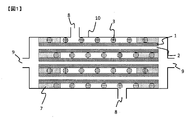
- FIG. 1 shows a schematic cross-sectional view of one aspect of the fluid separation membrane module of the present invention.
- FIG. 1 is a schematic cross-sectional view of a module containing a hollow thread-shaped fluid separation membrane, including an inflow port of the fluid to be separated.
- the module of the present invention includes a fluid separation membrane and a spacer. That is, in the module of the present invention, the fluid separation membrane 1 and the spacer 3 are housed in the vessel 10 having the outflow port 8 of the fluid to be separated.
- the fluid separation membrane 1 of FIG. 1 has a hollow portion 2.
- the fluid separation membrane is fixed at the potting site.
- the fluid separation membranes 1 bundled in parallel in FIG. 1 have both ends fixed to each other (potting) at the potting portion 7 and fixed to the vessel 10.
- the fluid separation membrane 1 penetrates the potting portion 7 and is connected to an external flow path (a flow path for recovering the fluid that has passed through the fluid separation membrane), which is not shown, from the outlet 9 of the permeated fluid of the vessel 10. Will be done.
- the module of the present invention is characterized in that the bundle L can be contracted in the circumferential direction even though the tensile elastic modulus of the fluid separation membrane is 1 GPa or more.
- a bundle of fluid separation membranes having a tensile elasticity of 1 GPa or more has poor contractility in the circumferential direction.
- the module of the present invention imparts contractility in the circumferential direction to the bundle L by accommodating a spacer having contractility together with the fluid separation film, and improves workability when storing the bundle L in the element casing. Damage to the fluid separation membrane due to stress concentration in the circumferential direction can be suppressed.
- the state in which the bundle L has contractility in the circumferential direction means a state in which the outer diameter of the bundle L becomes smaller when an external force such as purging the bundle L is applied in the circumferential direction of the bundle L.
- the external force referred to here represents an external force within a range in which the fluid separation membrane is not damaged.
- At least a part of the spacer has a bulk high compression ratio (hereinafter, may be referred to as “B c ”) measured by the JIS L 1013 (2010) B method of 10% or more and 95%.
- B c a bulk high compression ratio measured by the JIS L 1013 (2010) B method of 10% or more and 95%.
- the following fibers or rods When B c is 10% or more, the bundle L can be contracted by applying an external force.
- B c is preferably 20% or more, and more preferably 50% or more.
- B c is 95% or less, deformation of the fluid separation membrane in the vicinity of the spacer when the bundle L is contracted can be suppressed, so that damage to the membrane can be suppressed.
- B c is preferably 90% or less, more preferably 80% or less.
- the fiber or rod as a spacer preferably has a bulk high compressive elastic modulus (hereinafter, may be referred to as “ Be ”) measured by the JIS L 1013 (2010) B method of 30% or more and 100% or less. ..
- Be a bulk high compressive elastic modulus measured by the JIS L 1013 (2010) B method of 30% or more and 100% or less.
- Be is preferably 40% or more, and more preferably 50% or more.
- the upper limit of Be is not particularly limited, but is preferably 100% or less.
- At least a part of the spacer is a film having a compressibility measured by JIS L 1096 (2010) (hereinafter, may be referred to as “ Cr ”) of 10% or more and 95% or less.
- Cr a compressibility measured by JIS L 1096 (2010)
- the Cr is preferably 20% or more, more preferably 50% or more.
- Cr is 95% or less, deformation of the fluid separation membrane in the vicinity of the spacer when the bundle L is contracted can be suppressed, so that damage to the membrane can be suppressed.
- Cr is preferably 90% or less, more preferably 80% or less.
- the film, non-woven fabric, woven fabric, and knitted fabric as spacers preferably have a compressive elastic modulus (hereinafter, may be referred to as “Ce”) measured by JIS L 1096 (2010) of 30% or more and 100% or less. ..
- Ce compressive elastic modulus
- JIS L 1096 (2010) a force for restoring the outer diameter of the bundle L works when the external force for contracting the bundle L is removed.
- Ce is preferably 40% or more, more preferably 50% or more.
- the upper limit of Ce is not particularly limited, but is preferably 100% or less.
- At least a part of the spacer has a deformation strength (hereinafter, may be referred to as “ ⁇ 10% ”) measured by JIS Z 8844 (2019) of 0.1 kPa or more and 100 kPa or less. It is a particle.
- ⁇ 10% is 0.1 kPa or more, the movement of the fluid separation membrane in the vicinity of the spacer when the bundle L is contracted can be suppressed, so that the damage to the membrane can be suppressed.
- ⁇ 10% is preferably 1 kPa or more, and more preferably 5 kPa or more.
- the bundle L can be contracted by applying an external force.
- ⁇ 10% is preferably 50 kPa or less, and more preferably 10 kPa or less.
- the particles as spacers preferably have a fracture strength (hereinafter, may be referred to as “ ⁇ F ”) measured by JIS Z 8844 (2019) of 2 times or more and 10000 times or less of ⁇ 10% .
- ⁇ F fracture strength measured by JIS Z 8844 (2019) of 2 times or more and 10000 times or less of ⁇ 10% .
- ⁇ F is more than twice ⁇ 10%
- a force for restoring the outer diameter of the bundle L works when the external force for contracting the bundle L is removed.
- ⁇ F is preferably 10 times or more of ⁇ 10% , and more preferably 100 times or more.
- the upper limit of ⁇ F is not particularly limited, but is preferably 10000 times or less of ⁇ 10% .
- the bundle L is a bundle of all the fluid separation membranes and spacers in the module, it is preferable that the circumference of the bundle L satisfies the above formula 1.
- the bundle L is a bundle of all the fluid separation membranes 1 and the spacer 3 in FIG. 1.
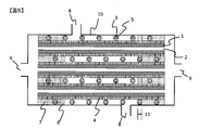
- FIG. 2 shows a schematic diagram of one aspect of a method of measuring the circumference of the outer circumference of the bundle L when the measuring thread is wound once in a direction orthogonal to the long axis of the fluid separation membrane.
- the measurement yarn means a false-twisted polyethylene terephthalate yarn having a total fineness of 3000 dtex and 480 filaments.
- the circumference of the bundle L of the present invention is measured using a measuring thread. That is, in the bundle L; 13 in FIG. 2, the measuring thread 14 is wound around the outer circumference of the bundle L in a direction orthogonal to the long axis of the fluid separation membrane. One end of the measuring thread 14 is fixed, and the weight 15 is fixed to the other end.
- the circumference of the bundle L is the length of the portion around which the measuring thread is wound. That is, in the circumference 16 of the bundle L; 13 in FIG. 2, after the start point and the end point at which the measurement thread 14 goes around the bundle L; 13 are set to points A and B, the bundle L is removed and the measurement thread is straightened. It can be expressed by the distance between points A and B.
- the circumference of the bundle L when the measurement thread is pulled with a force of 5 N / m with respect to the circumference of the bundle L is L 1
- the measurement thread is with respect to the circumference of the bundle L.
- L 2 / L 1 is 0.50 or more and 0.95 or less.
- L 2 / L 1 is 0.50 or more
- the ratio of the fluid separation membrane contained in the bundle L increases, so that the membrane area per module unit volume can be increased.
- L 2 / L 1 is more preferably 0.60 or more, and further preferably 0.75 or more.
- L 2 / L 1 is 0.95 or less, the bundle L is imparted with contractility in the circumferential direction, so that damage to the fluid separation membrane when the bundle L is housed in the module is suppressed.
- L 2 / L 1 is more preferably 0.90 or less, and even more preferably 0.85 or less.
- the length when a load of 5 N is applied in the fiber axis direction is L 3
- the length when a load of 50 N is applied in the fiber axis direction is L 4
- L 4 / L Use a measuring thread in which 3 is 1.05 or less.
- the mixed gas and mixed liquid to be separated by the module of the present invention are not particularly limited, but for example, a carbon dioxide separation / storage system from exhaust gas of a power plant, a blast furnace, etc., and a gas in a coal gasification combined power generation. Examples include removal of sulfur components from the converted fuel gas, purification of biogas and natural gas, and purification of hydrogen from organic hydride. That is, in the module of the present invention, the fluid separation membrane is preferably a gas separation membrane.
- the cross-sectional shape of the vessel is preferably elliptical or circular, and more preferably circular, from the viewpoint of improving the pressure resistance of the vessel.
- the cross section of the vessel means the cross section of the vessel perpendicular to the length direction of the fluid separation membrane.
- the material of the vessel include metal, resin, fiber reinforced plastic (FRP), and the like, which can be appropriately selected depending on the environment of the installation location and the situation in which the vessel is used. In applications where pressure resistance and heat resistance are required, a metal having both strength and formability is preferable, and stainless steel or the like is more preferable.
- the outflow port of the fluid to be separated which is arranged in the vessel, has a function of guiding the fluid to be separated to the fluid separation membrane.
- the fluid separation membrane When the fluid separation membrane is used in the total volume filtration method, it is sufficient to have one inflow port of the fluid to be separated, and when it is used in the cross flow filtration method, the outflow port of the fluid to be separated is combined. It is preferable to have two or more places. There may be a plurality of outflow ports of the fluid to be separated as long as the mechanical strength of the vessel is maintained. In this case, it is preferable to dispose a cloth such as mesh or felt between the outflow port and the fluid separation membrane within a range that does not obstruct the passage of the fluid, and it is effective in diffusing the fluid and protecting the fluid separation membrane.
- a method of fixing the fluid separation membrane to the vessel a method of directly fixing the fluid separation membrane to the inner surface of the vessel with a potting material, or a separation membrane element in which a plurality of fluid separation membranes are fixed by the potting material is used.
- Examples thereof include a method of fixing in the vessel via an adapter or the like (for example, an O-ring or the like) capable of ensuring liquidtightness or airtightness. Since only the separation membrane element can be replaced when the performance of the separation membrane element deteriorates over time, it is preferable to fix the separation membrane element in the vessel via an adapter or the like.
- the potting portion of the module or the separation membrane element may be one place or a plurality of places, but is omitted from the viewpoint of sufficiently fixing the position of the fluid separation membrane and maintaining the effective surface area of the fluid separation membrane. It is preferable to fix the two ends of the plurality of fluid separation membranes bundled in a straight line with a potting material. Further, both ends of the fluid separation membrane may be fixed with a potting material at one place in a state where a plurality of bundled fluid separation membranes are bent into a U shape, or only one end of the fluid separation membrane is fixed with the potting material. The other end may be sealed by means other than the potting material.
- the separation membrane element of the present invention may have a casing (hereinafter referred to as "element casing") different from the vessel.
- the element casing preferably has an outflow port for the fluid to be separated.
- the shape of the element casing is not particularly limited as long as it does not interfere with the storage in the vessel. Examples of the material of the element casing include metal, resin, fiber reinforced plastic (FRP) and the like, which can be appropriately selected depending on the situation in which the element casing is used.
- Resin is preferable because it has high followability to the curing shrinkage of the potting material, and polyphenylene sulfide, polytetrafluoroethylene, polyethylene, polypropylene, polyether ether ketone, polyphenylene ether, and polyether because it has both moldability and chemical resistance. Idyl, polyamide-imide and polysulfone are more preferred.
- the inner diameter of the element casing is preferably L 2 / ⁇ or more and 1.5 L 1 / ⁇ or less.
- the inner diameter of the element casing is more preferably (L 1 + L 2) / 2 ⁇ or more, and further preferably L 1 / ⁇ or more.
- the inner diameter of the element casing is 1.5 L 1 / ⁇ or less, the film area per element unit volume can be increased.
- the inner diameter of the element casing is more preferably 1.2 L 1 / ⁇ or less, and further preferably 1.1 L 1 / ⁇ or less.
- the preferable inner diameter of the element casing is the preferred inner diameter of the vessel.
- the module of the present invention may have a central pipe or the like in the element casing.
- it can be regarded as a bundle L including the central pipe and the like.
- the potting material examples include a thermoplastic resin and a thermosetting resin. Further, other additives may be contained.
- thermoplastic resin used as the potting material examples include polyethylene, polyether sulfone, polystyrene, polyphenylene sulfide, polyarylate, polyester, liquid crystal polyester, polyamide, polymethylmethacrylate and the like.
- thermosetting resin examples include epoxy resin, unsaturated polyester resin, urethane resin, urea resin, phenol resin, melamine resin, silicone resin and the like. Two or more of these may be used. Among these, epoxy resin and urethane resin are preferable from the viewpoint of balance of moldability, curing time, adhesiveness, hardness and the like.
- additives preferably used in potting materials include fillers, surfactants, silane coupling agents, rubber components and the like.
- the filler include silica, talc, zeolite, calcium hydroxide, calcium carbonate and the like, which have effects such as suppression of curing heat generation, strength improvement and thickening.
- the surfactant and the silane coupling agent have the effects of improving the handleability when the potting material is mixed and improving the infiltration property between the carbon films for fluid separation when the potting material is injected.
- the rubber component has the effect of improving the toughness of the cured and molded potting material.
- the rubber component may be contained in the form of rubber particles.
- the fluid separation membrane is a membrane in which the permeability of a specific component (permeable component) contained in the fluid to be separated is higher than that of other components (non-permeable component).
- the shape of the fluid separation membrane is not particularly limited and may be a flat membrane or a hollow fiber membrane. However, when the separation membrane module is used, the membrane area per module unit volume tends to be large, so that the fluid is fluid.
- the separation membrane is preferably a hollow fiber membrane.
- the inner diameter of the hollow fiber membrane is preferably 10 ⁇ m or more and 2,000 ⁇ m or less. By setting the inner diameter of the hollow fiber membrane to 10 ⁇ m or more, the permeability of the fluid can be improved.
- the inner diameter of the hollow fiber membrane is more preferably 20 ⁇ m or more, further preferably 50 ⁇ m or more.
- the outer diameter of the hollow fiber membrane can be reduced, so that the membrane area of the fluid separation membrane per unit volume in the case of a fluid separation membrane module can be increased. Can be done.
- the inner diameter of the fluid separation membrane is more preferably 1,000 ⁇ m or less, further preferably 500 ⁇ m or less.
- the fluid separation membrane examples include a zeolite membrane, a metal-organic framework (MOF) membrane, an inorganic membrane such as a carbon membrane, and a polymer membrane.
- MOF metal-organic framework
- the fluid separation membrane module is preferably an inorganic membrane having excellent heat resistance and chemical resistance, and may be a zeolite membrane or a carbon membrane. preferable. Above all, a carbon film is more preferable.
- Zeolite membranes suitable as fluid separation membranes include aluminosilicates, for example, membranes made of NaX type (FAU), ZSM-5, MOR, silicalite, A type and the like. Two or more of these may be used. Zeolites are preferably those having a Si / Al ratio similar to that of the zeolite that is secondarily grown by a hydrothermal synthesis reaction.
- Suitable MOF membranes as fluid separation membranes include, for example, Cu-BTC, MOF-5, IRMOF-3, MIL-47, MIL-53, MIL-96, MMOF, SIM-1, ZIF-7, ZIF-8. , ZIF-22, ZIF-69, ZIF-90 and the like. Two or more of these may be used.
- Suitable carbon films for the fluid separation film include, for example, polyphenylene oxide, polyvinyl alcohol, polyacrylonitrile, phenol resin, total aromatic polyester, unsaturated polyester resin, alkyd resin, melamine resin, urea resin, polyimide resin, and diallyl phthalate resin. , A film obtained by carbonizing a lignin resin, a urethane resin, or the like. Two or more of these may be used.
- Suitable polymer films for the fluid separation film include, for example, aromatic polyimide, cellulose acetate, polysulfone, aromatic polyamide, polyetherimide, polyethersulfone, polyacrylonitrile, polyphenylene sulfide, polyether ether ketone, polytetrafluoroethylene.
- Polyfluoride vinylidene poly (1-trimethylsilylpropin), polydimethylsiloxane, polyvinyltrimethylsilane, poly (4-methylpentene), ethylcellulose, natural rubber, poly (2,6-dimethyloxide phenylene), low density polyethylene, Examples thereof include a film made of high-density polyethylene, styrene, polyethylmethacrylate, polycarbonate, polyester, aliphatic polyamide, polymethylmethacrylate, polyvinyl alcohol, silicone and the like. Two or more of these may be used.
- Nanoparticles and the like can be added to the fluid separation membrane in order to improve the permeability of the permeable component.
- nanoparticles include silica, titania, zeolite, metal oxide, MOF, carbon nanotube (CNT) and the like.
- the fluid separation membrane of the present invention may include a support.
- the support is arranged only on one surface of the fluid separation membrane.
- the support examples include porous inorganic materials such as alumina, silica, cordierite, zirconia, titania, bicole glass, zeolite, magnesia, and sintered metal, polysulfone, polyethersulfone, polyamide, polyester, and cellulose-based polymers.
- Examples of the carbonizable resin include polyphenylene oxide, polyvinyl alcohol, polyacrylonitrile, phenol resin, total aromatic polyester, unsaturated polyester resin, alkyd resin, melamine resin, urea resin, polyimide resin, diallyl phthalate resin, lignin resin, and urethane. Examples include resin. Two or more of these may be used.
- the fluid separation membrane of the present invention has a coating layer (hereinafter referred to as coating layer 1) on at least a part of the surface thereof.
- coating layer 1 it is more preferable that the coating layer 1 is arranged only on one surface of the fluid separation membrane.
- the coating layer 1 is a layer that covers at least a part of the surface of the fluid separation membrane. Can be coated to improve separation selectivity.
- the coating layer 1 examples include a layer containing at least one compound selected from the group consisting of polyolefin, fluororesin, polystyrene, silicone, microporous polymer (PIM), phenol resin, and urethane resin. Since it is easy to coat the surface of the fluid separation membrane, it is more preferable to contain at least one compound selected from the group consisting of silicone and PIM.
- the abundance ratio of the above compound contained in the coating layer 1 is preferably 20 wt% or more and 100 wt% or less with respect to the total weight of the coating layer 1 of 100 wt%.
- the abundance ratio of the compound contained in the coating layer 1 is more preferably 50 wt% or more, further preferably 80 wt% or more.
- polyolefin suitable as the compound in the coating layer 1 examples include polyethylene, polypropylene, polymethylpentene and the like.
- fluororesin suitable as the compound in the coating layer 1 examples include tetrafluoroethylene and the like.
- silicone suitable as the compound in the coating layer 1 examples include polydimethylsiloxane.
- the phenol resin suitable as the compound in the coating layer 1 is a resin obtained by reacting phenols with aldehydes, and for example, a water-soluble phenol resin solution in which phenols and aldehydes are polycondensed and a water-soluble phenol resin solution. It is a phenolic resin formed by an opposite diffusion reaction with a hardening gas.
- the above-mentioned water-soluble phenol resin solution contains, for example, a phenol resin obtained by reacting phenols including phenol, cresol, resorcinol, bisphenol A, and other substituted phenols with an aldehyde compound or the like under an alkaline catalyst. Etc. are included.
- the curing gas for the water-soluble phenolic resin solution examples include acidic gases such as carbon dioxide, hydrogen sulfide, sulfur oxides, nitrogen oxides, inorganic acids (hydrogen chloride and the like), organic acids (carboxylic acids and the like), and the like.
- acidic gases such as carbon dioxide, hydrogen sulfide, sulfur oxides, nitrogen oxides, inorganic acids (hydrogen chloride and the like), organic acids (carboxylic acids and the like), and the like.
- examples thereof include a gas that produces an acid by reacting with a water-soluble phenol resin solution such as an ester (organic ester, inorganic ester, etc.).
- a plurality of curing gases may be mixed and used, or a mixed gas with an inert gas may be used.
- the urethane resin suitable as the compound in the coating layer 1 is a resin obtained by a double addition reaction of a polyol compound and a polyisocyanate compound.
- phenol resins obtained by reacting phenols including phenol, cresol, resorcinol, bisphenol A, and other substituted phenols with aldehyde compounds and the like under an alkaline catalyst. Will be.
- the polyisocyanate compound is an organic compound having two or more isocyanates in one molecule, and includes aliphatic and aromatic polyisocyanate compounds, and modified products thereof.
- aliphatic polyisocyanate include hexamethylene diisocyanate, isophorone diisocyanate, dicyclohexylmethane diisocyanate, methylcyclohexanediisocyanate and the like
- aromatic polyisocyanate include toluene diisocyanate, diphenylmethane diisocyanate, polypeptide diphenylmethane diisocyanate and the like.
- these modified products include carbodiimide modified products and prepolymer modified products.
- Examples of the amine gas used for forming the urethane resin include triethylamine, dimethylethylamine, dimethylisopropylamine and the like.
- the thickness of the coating layer 1 is not particularly limited, but is preferably 0.1 ⁇ m or more and 100 ⁇ m or less. When the thickness of the coating layer 1 is 0.1 ⁇ m or more, the portion of the surface of the fluid separation film to be coated can be reliably coated.
- the thickness of the coating layer 1 is more preferably 1 ⁇ m or more, further preferably 2 ⁇ m or more. On the other hand, when the thickness of the coating layer 1 is 100 ⁇ m or less, the filling rate of the fluid separation membrane in the fluid separation membrane module and the permeability of the fluid to be separated can be maintained.
- the thickness of the coating layer 1 is more preferably 50 ⁇ m or less, further preferably 20 ⁇ m or less.
- the thickness of the coating layer 1 can be measured, for example, by observing the cross section of the fluid separation membrane having the coating layer 1 with a transmission electron microscope (SEM) or the like.
- the cross section of the fluid separation membrane having the coating layer 1 is formed by embedding the fluid separation membrane having the coating layer 1 in a resin or the like that can be distinguished from the coating layer 1 at the time of observation, and cutting in a direction perpendicular to the depth direction of the coating layer 1. Obtained by doing.
- the tensile elastic modulus of the fluid separation membrane is preferably 1.5 GPa or more.
- the tensile elastic modulus of the fluid separation membrane is more preferably 2.0 GPa or more, further preferably 3.0 GPa or more.
- the upper limit of the tensile elastic modulus of the fluid separation membrane is not particularly limited, but is preferably 500 GPa or less, and when it is 500 GPa or less, damage during transportation or module operation can be suppressed.
- the tensile elastic modulus is more preferably 300 GPa or less, and further preferably 100 GPa or less.
- the tensile elastic modulus of the fluid separation membrane can be measured by a tensile test.
- the tensile elastic modulus of the fluid separation membrane having the support or the coating layer 1 is regarded as the tensile elastic modulus of the fluid separation membrane.
- the fluid separation membrane preferably has a bending radius of 100 cm or less.
- the bending radius of the fluid separation membrane is 100 cm or less, it is possible to suppress the breakage of the fluid separation membrane during the production or operation of the module.
- the bending radius is more preferably 10 cm or less, further preferably 5 cm or less.
- the lower limit of the bending radius of the fluid separation membrane is not particularly limited, but 0.1 cm or more is preferable, and 0.1 cm or more improves the morphological stability when the fluid separation membrane is handled as a bundle. Module manufacturing efficiency is improved.
- the bending radius is more preferably 0.2 cm or more, and further preferably 0.5 cm or more.
- the bending radius of the fluid separation film is obtained from the radius of the cylinder in which the fluid separation film is sampled from the module by 10 cm or more and the sampled fluid separation film is wound 360 ° or more along the normal direction of the cylinder so that the fluid separation film does not break. be able to.
- the bending radius of the fluid separation film is 1.5 cm or more, the angle at which the sampled fluid separation film is wound along the normal direction of the cylinder is appropriately reduced for evaluation, and the radius of the cylinder at which the fluid separation film does not break is determined. , Can be regarded as the bending radius of the fluid separation film.
- the bending radius of the fluid separation membrane having the support or the coating layer 1 is regarded as the bending radius of the fluid separation membrane.
- the water permeability of the fluid separation membrane of the present invention is preferably 0 ⁇ L / hr / m 2 / Pa or more and 100 ⁇ L / hr / m 2 / Pa or less.
- a fluid separation membrane having a water permeability of 100 ⁇ L / hr / m 2 / Pa or less can be suitably used as a gas separation membrane because the pore diameter of the separation functional layer is small.
- the water permeability of the fluid separation membrane is more preferably 10 ⁇ L / hr / m 2 / Pa or less, further preferably 1 ⁇ L / hr / m 2 / Pa or less.
- the permeability of the fluid separation membrane can be calculated by the following formula 3 from the amount of permeated water recovered from the outflow port of the permeation fluid of the module when pure water is supplied from the outflow port of the fluid to be separated of the module. can.
- Qw represents the amount of permeated water ( ⁇ L)
- P represents the pressure of the feed water (Pa)
- T represents the water permeation time (hr)
- A represents the fluid separation membrane having the coating layer 1.
- the water permeability of the fluid separation membrane having the support or the coating layer 1 is regarded as the water permeability of the fluid separation membrane.
- the spacer is arranged in the module together with the fluid separation membrane, and has the effect of imparting contractility in the circumferential direction to the bundle L, which is a bundle of all the fluid separation membranes and the spacer in the module.
- the arrangement of the fluid separation membrane and the spacer in the bundle L is not particularly limited, and the fluid separation membrane may be arranged around the spacer, or the spacer may be arranged around the bundle of the fluid separation membrane, and the fluid may be arranged. Spacers may be arranged between the separation membranes. The arrangement may be a combination of these. It is more preferable that at least a part of the spacer is arranged between the fluid separation membranes because the passage of the fluid to be separated becomes uniform.
- the spacer is not particularly limited, but is preferably selected from the group consisting of films, non-woven fabrics, woven fabrics, knitted fabrics, fibers, rods, and particles. Two or more of these may be combined. Since it is easy to place between the fluid separation membranes, the spacer when the fluid separation membrane is a flat membrane is preferably a film, a non-woven fabric, a woven fabric, or a knitted fabric, and when the fluid separation membrane is a hollow fiber membrane, the spacer is It is preferably a fiber and a rod.
- spacer examples include polyester, nylon, polyolefin, fluororesin, polyacetal, thermoplastic elastomer, metal oxide and the like. Two or more of these may be used.
- the spacer When the spacer is a fiber, the spacer may be a monofilament or a multifilament, but a multifilament is preferable because it is flexible and has excellent handleability. Further, it is more preferable to use false twisted yarn as the spacer because it is bulky and it is easy to secure the distance between the fluid separation membranes. As the false twisted yarn suitable as a spacer, polyester yarn and nylon yarn are preferable because false twisting is easy.
- the present invention also has an embodiment in which the spacer spirally covers the circumference of one or more fluid separation membranes. Is one of the preferred embodiments of.
- FIG. 3 and 4 show a schematic diagram of one aspect in which a spacer spirally covers the periphery of one or more fluid separation membranes.
- FIG. 3 is a schematic view of one embodiment in which one spacer 3 is spirally covered with one fluid separation membrane 1 at intervals of pitch 12, and
- FIG. 4 is a schematic view of two fluid separation membranes. It is a schematic diagram of one aspect in which two spacers 3 are spirally covered with an interval of pitch 12 with respect to 1.
- the coating around the fluid separation membrane by the spacer may be a single covering in which the spacer is wound once or a double covering in which the spacer is doublely wound around the fluid separation membrane.
- multi-stage covering in which the second spacer is further spirally wound with respect to a plurality of fluid separation membranes in which the first spacer is spirally wound is also one of the preferred embodiments of the present invention.
- the first spacer and one or more fluid separation membranes wound by the first spacer are collectively referred to as a bundle S
- the second spacer and one or more bundles S wound by the second spacer are collectively referred to as a bundle M.
- a plurality of fluid separation membranes, a bundle S, and a bundle M may be collectively formed as a bundle L.
- the occupied volume of the second spacer in the bundle M is smaller than the occupied volume of the first spacer in the bundle M. Since the occupied volume of the second spacer in the bundle M is smaller than the occupied volume of the first spacer in the bundle M, it is easy to secure the distance between the fluid separation membranes. Therefore, when the viscosity of the fluid to be separated is high. It can be suitably used even when the fluid to be separated has a large amount of agglomerating components.
- the ratio of the occupied volume of the first spacer to the bundle M to the occupied volume of the second spacer in the bundle M (that is, "the occupied volume of the first spacer in the bundle M" / "the second occupied volume in the bundle M”.
- the occupied volume of the spacer is more preferably 1.2 or more, and further preferably 1.5 or more.
- the upper limit of the ratio of the occupied volume of the first spacer to the occupied volume of the bundle M to the occupied volume of the second spacer in the bundle M is not particularly limited, but is preferably 100 or less, and the module volume is preferably 100 or less.
- the membrane area of the fluid separation membrane can be secured.
- the ratio of the occupied volume of the first spacer to the occupied volume of the bundle M to the occupied volume of the second spacer in the bundle M is more preferably 50 or less, and further preferably 10 or less.
- the occupied volume of the second spacer in the bundle M is larger than the occupied volume of the first spacer in the bundle M. Since the occupied volume of the second spacer in the bundle M is larger than the occupied volume of the first spacer in the bundle M, the fluid separation membranes in the bundle M are close to each other, so that the tensile load of the bundle M is improved. And the handleability is improved.
- the ratio of the occupied volume of the second spacer to the bundle M to the occupied volume of the first spacer in the bundle M that is, "the occupied volume of the second spacer in the bundle M" / "the first occupied in the bundle M".
- the occupied volume of the spacer is more preferably 1.2 or more, and further preferably 1.5 or more.
- the upper limit of the ratio of the occupied volume of the second spacer to the occupied volume of the bundle M to the occupied volume of the first spacer in the bundle M is not particularly limited, but is preferably 100 or less, and the module volume is preferably 100 or less.
- the membrane area of the fluid separation membrane can be secured.
- the ratio of the occupied volume of the second spacer to the occupied volume of the bundle M to the occupied volume of the first spacer in the bundle M is more preferably 50 or less, and further preferably 10 or less.
- the occupied volume of the spacer is adjusted so that the first spacer or the second spacer collected from the bundle M of a certain length is stored in a cylindrical container and the weight is 0.15 g / cm 2 with respect to the cross-sectional area of the cylinder.
- the height L 0 of the spacer after placing the circular plate on the spacer and leaving it for 1 minute can be measured and calculated from the following formula 4.
- the dispersibility of the fluid separation film in the module can be evaluated.
- the area of the Voronoi region is the area of the region partitioned by the Voronoi division.
- Voronoi division is a method of dividing a plane surrounded by generatrix, which has a plurality of generatrix, by a perpendicular bisector between adjacent generatrix and an intermediate line between the generatrix and the generatrix adjacent to each other. That is, the higher the dispersibility of the fluid separation membrane in the module, the more uniform the area of the Voronoi region of the fluid separation membrane.
- the area of the Voronoi region of the fluid separation film in the cross section perpendicular to the longitudinal direction of the module satisfies the following formula 2.
- S 0 ⁇ r ⁇ 50 / S 50 ⁇ r ⁇ 100 is larger than 0.5, the number of fluid separation membranes housed in the outer edge of the module having a large volume increases, so that the membrane area per module unit volume is increased. be able to.
- S 0 ⁇ r ⁇ 50 / S 50 ⁇ r ⁇ 100 is more preferably 1 or more, and further preferably 1.5 or more.
- S 0 ⁇ r ⁇ 50 / S 50 ⁇ r ⁇ 100 is smaller than 10, the gap between the bundle L and the element casing and the like can be reduced, and the short path of the fluid to be separated can be suppressed.
- S 0 ⁇ r ⁇ 50 / S 50 ⁇ r ⁇ 100 is more preferably 5 or less, and further preferably 2 or less.
- Equation 2 [In the equation, S 0 ⁇ r ⁇ 50 is the area of the boronoy region of the fluid separation membrane in the region where the distance from the center of the fluid separation membrane storage region is 0% or more and less than 50% of the radius of the fluid separation membrane storage region. Representing an average value, S 50 ⁇ r ⁇ 100 is the area of the boronoy region of the fluid separation membrane in the region where the distance from the center of the fluid separation membrane storage region is more than 50% and 100% or less of the radius of the fluid separation membrane storage region. Represents the average value.
- the cross section perpendicular to the longitudinal direction of the module is perpendicular to the longitudinal direction of the fluid separation membrane of the module after injecting thermosetting resin from the outflow port of the fluid to be separated of the module to fix the position of the fluid separation membrane in the module. Obtained by cutting on a surface.
- the area of the Voronoi region of the fluid separation membrane can be obtained by image analysis of the above cross section. More specifically, by performing Voronoi division with the center of gravity of each fluid separation membrane in the above cross-sectional image as the generatrix and the boundary line of the fluid separation membrane storage region as the generatrix, the area of the Voronoi region can be determined for each fluid separation membrane. Can be calculated.
- Examples of the boundary line of the fluid separation membrane storage region include the inner surface of the element casing or vessel, and the outer surface of the central pipe or the like.
- S 0 ⁇ r ⁇ 50 is the boronoy region in the fluid separation membrane in which the boronoy region is included in the region where the distance from the center of the fluid separation membrane storage region is 0% or more and less than 50% of the radius of the fluid separation membrane storage region.
- S 50 ⁇ r ⁇ 100 is a fluid in which the boronoy region is included in a region where the distance from the center of the fluid separation membrane storage region is more than 50% and 100% or less of the radius of the fluid separation membrane storage region.
- a coating layer (hereinafter referred to as coating layer 2) may be provided on the surface of the spacer.
- the presence of the coating layer 2 on at least a part of the surface of the spacer can control the friction between the fluid separation membrane and the coating layer 2, reduce the friction and prevent damage to the fluid separation membrane due to stress concentration. Friction can be increased to fix the position of the spacer.
- at least a part of the spacer is arranged between the membranes of the fluid separation membrane, it is possible to uniformly pass the fluid to be separated by suppressing the displacement of the spacer during the production or operation of the separation membrane module. can.
- damage to the surface of the fluid separation membrane due to friction between the fluid separation membrane and the spacer can be further suppressed.
- the above-mentioned coating layer 1 may be provided on at least a part of the surface of the fluid separation membrane.
- the coating layer 2 may have the same composition as the coating layer 1 or may have a different composition. Further, the coating layer 1 and the coating layer 2 may have a clear boundary or may be integrated.
- the fluid separation membrane is fixed at the potting portion, and a coating layer (hereinafter referred to as coating layer 3) may be provided on the surface of the potting portion on the inner side of the fluid separation membrane module.
- a coating layer hereinafter referred to as coating layer 3
- the coating layer 3 is preferably an elastomer. Since the coating layer 3 is an elastomer, the vibration of the fluid separation membrane in the vicinity of the potting portion during the production or operation of the module is reduced, and damage to the fluid separation membrane can be suppressed.
- Examples of the elastomer suitable for the coating layer 3 include a thermosetting elastomer and a thermoplastic elastomer, which are appropriately selected according to the operating conditions of the module.
- Examples of the thermosetting elastomer include vulcanized rubber, urethane rubber, silicone rubber, and fluororubber.
- Examples of the thermoplastic elastomer include polystyrene-based elastomers, olefin-based elastomers, polyvinyl chloride-based elastomers, polyurethane-based elastomers, polyester-based elastomers, polyamide-based elastomers, and acrylic-based elastomers.
- the coating layer 3 may have the same composition as the coating layer 1 and the coating layer 2, or may have a different composition. Further, the coating layer 3, the coating layer 1 and the coating layer 2 may have a clear boundary or may be integrated. From the viewpoint of workability at the time of manufacturing the fluid separation membrane module, it is preferable that the coating layer 1, the coating layer 2, and the coating layer 3 have the same composition.
- the thickness of the coating layer 3 is preferably 10 ⁇ m or more and 50,000 ⁇ m or less. When the thickness of the coating layer 3 is 10 ⁇ m or more, it is possible to reduce the vibration of the fluid separation membrane in the vicinity of the potting portion during operation of the fluid separation membrane module.
- the thickness of the coating layer 3 is more preferably 100 ⁇ m or more, further preferably 1000 ⁇ m or more. On the other hand, when the thickness of the coating layer 3 is 50,000 ⁇ m or less, the surface area of the fluid separation membrane can be sufficiently secured.
- the thickness of the coating layer 3 is more preferably 20000 ⁇ m or less, further preferably 10,000 ⁇ m or less.
- the thickness of the coating layer 3 can be measured, for example, by observing the cross section of the potting portion having the coating layer 3 with a transmission electron microscope (SEM) or the like.
- the cross section of the potting portion having the coating layer 3 is formed by embedding the potting portion having the coating layer 3 with a resin or the like that can be distinguished from the coating layer 3 at the time of observation, and cutting in a direction perpendicular to the depth direction of the coating layer 3. Obtained at.
- the composition of the coating layer can be analyzed by elemental analysis of the coating layer or the like.
- FIG. 5 shows a schematic cross-sectional view of another aspect of the fluid separation membrane module of the present invention.
- FIG. 5 is a schematic cross-sectional view of a module containing a hollow thread-shaped fluid separation membrane and having coating layers 1 to 3 including an inflow port of the fluid to be separated.
- the module of the present invention preferably has a coating layer 1 on at least a part of the surface of the fluid separation membrane. That is, the fluid separation membrane 1 of FIG. 5 has a hollow portion 2 and a coating layer 1; 4 on the surface.
- the module of the present invention preferably has a coating layer 2 on the surface of the spacer. That is, the spacer 3 in FIG. 5 has a coating layer 2; 5 on its surface.
- the fluid separation membrane is fixed at the potting portion, and it is preferable that the coating layer 3 is provided on the surface of the potting portion on the inner side of the fluid separation membrane module.
- the fluid separation membranes 1 bundled in parallel in FIG. 5 have both ends fixed to each other (potting) at the potting portion 7 and fixed to the vessel 10.
- the potting site 7 has a coating layer 3; 6 on the inner surface of the fluid separation membrane module.
- the fluid separation membrane plant of the present invention (hereinafter, may be simply referred to as "plant") is a plant including the fluid separation membrane module of the present invention.
- the plant preferably includes pretreatment equipment, purified fluid recovery equipment, by-product fluid recovery equipment, etc. in addition to the module.
- the pretreatment equipment is equipment for removing impurities from the separation target fluid before separation and adjusting the composition of the separation target fluid before separation.
- the purified fluid recovery facility is a facility for recovering a purified fluid from which unnecessary components have been removed from the fluid to be separated before separation, and further purifying or supplying the purified fluid to a pipeline or the like as necessary.
- the by-product fluid recovery facility is a facility that recovers the by-product fluid removed from the separation target fluid before separation and discharges it after detoxification as an example.
- the module and the pretreatment equipment, the purified fluid recovery equipment, the by-product fluid recovery equipment are connected by pipes, etc., and the fluid to be separated before separation is continuously separated into the purified fluid and the by-product fluid. Is preferable.
- the plant preferably includes a plurality of modules according to the processing amount of the fluid to be separated.
- the plurality of modules may be connected in series to the fluid to be separated, or may be connected in parallel. From the viewpoint of module manufacturing efficiency, the modules are preferably connected in series, and from the viewpoint of being able to partially replace the modules, the modules are preferably connected in parallel.
- a preferred embodiment of the plant of the present invention is an embodiment in which modules are connected in series and modules connected in series are further connected in parallel. By doing so, it is possible to achieve both the merits of connecting modules in series and the merits of connecting modules in parallel.
- the mixed gas and mixed liquid to be separated by the plant of the present invention are not particularly limited, but for example, a carbon dioxide separation / storage system from exhaust gas of a power plant, a blast furnace, etc., and a gas in a coal gasification combined power generation. Examples include removal of sulfur components from the converted fuel gas, purification of biogas and natural gas, and purification of hydrogen from organic hydride. That is, in the plant of the present invention, the fluid separation membrane is preferably a gas separation membrane.
- the purified fluid of the present invention is a fluid purified by the fluid separation membrane module of the present invention.
- the purified fluid may be purified by including another purification step or an additional step before and after the purification step in the module of the present invention, or may be mixed with a purification fluid purified by a different purification step.
- Other purification steps and different purification steps include, for example, distillation, adsorption, absorption and the like.
- component adjustment to be mixed with another fluid can be mentioned.
- the purification fluid of the present invention consumes a small amount of energy required for purification in the module, it can be suitably used in various industrial applications as a purification fluid having a low environmental load.
- a spacer is spirally wound around a fluid separation membrane to form a bundle S, and a bundle L composed of a plurality of bundles S is inserted into an element casing or a vessel, and a potting material is used.
- the case of fixing will be described as an example.
- One fluid separation membrane is used as the core thread, and the spacer is spirally wound to form a bundle S.
- the device for spirally winding the spacer include a covering twisting machine and a double covering twisting machine.
- a plurality of the obtained bundles S are bundled into a bundle L, inserted into the element casing or vessel, and then one end or both ends of the covering carbon film are potted with a potting material.
- a contraction force in the circumferential direction is applied to the end of the bundle L to reduce the outer diameter of the end of the bundle L, and then the bundle L is stored in the element casing or vessel. preferable.
- a potting method for example, a centrifugal potting method in which centrifugal force is used to permeate between fluid separation membranes, and a static potting material in which a fluidized potting material is sent by a metering pump or a head and permeated into a carbon film for fluid separation is allowed to stand.
- a potting method for example, a centrifugal potting method in which centrifugal force is used to permeate between fluid separation membranes, and a static potting material in which a fluidized potting material is sent by a metering pump or a head and permeated into a carbon film for fluid separation is allowed to stand. Examples include the potting method.
- a cap as a pipe joint member to the cut surface of the fluid separation membrane module so that it can be connected to an external flow path (a flow path for collecting the fluid that has passed through the fluid separation membrane, etc.).
- the mixed fluid to be separated by the module of the present invention is not particularly limited, but for example, a carbon dioxide separation / storage system from exhaust gas of a power plant, a blast furnace, etc., and a gasified fuel in a coal gasification combined power generation.
- a carbon dioxide separation / storage system from exhaust gas of a power plant, a blast furnace, etc.
- a gasified fuel in a coal gasification combined power generation examples include removal of sulfur components from gas, purification of biogas and natural gas, and purification of hydrogen from organic hydride.
- both ends of the sampled fluid separation membrane were reinforced with an adhesive by 1 cm, and the reinforced portion was fixed to the chuck of a tensile tester (TENSILON (registered trademark) / RTM-100, manufactured by Toyo Baldwin Co., Ltd.), and the sample length was obtained.
- the tensile elastic modulus (GPa) was measured under the conditions of 80 mm and a tensile speed of 10 mm / min. The measurement was performed 10 times each, and the average value indicated by two significant figures was taken as the tensile elastic modulus of the fluid separation membrane.
- Spacers were sampled from the fluid separation membrane modules of Examples 1 to 6 and Comparative Example 2, and the bulk high compressibility and the bulk high compressibility were measured according to the JIS L 1013 (2010) B method.
- the measurement thread was wound around the outer circumference of the bundle L in a direction orthogonal to the major axis of the fluid separation membrane, and the circumference of the bundle L when the pulling force of the measurement thread was changed was measured.
- the circumferential contractility (L 2 / L 1 ) of the bundle L is the measurement thread with respect to the circumference L 1 of the bundle L when the measurement thread is pulled with a force of 5 N / m with respect to the circumference length of the bundle L.
- thermosetting resin is injected from the outflow port of the fluid to be separated of the acrylic pipe to fix the position of the fluid separation film in the module, and then the vicinity of the center of the longitudinal direction of the module is in the longitudinal direction of the fluid separation film.
- a cross-sectional image was obtained by cutting on a vertical plane. Voronoi division was performed with the center of gravity of each fluid separation film in the obtained cross-sectional image as a generatrix and the inner surface of the acrylic pipe as a generatrix, and the area of the Voronoi region was calculated for each fluid separation film.
- the average value of the area of the boronoy region and the distance from the center of the acrylic pipe in the fluid separation membrane in which the boronoy region is included in the region where the distance from the center of the acrylic pipe is 0% or more and less than 50% of the radius of the acrylic pipe Obtain the average value of the area of the boronoy region in the fluid separation membrane in which the boronoy region is included in the region of more than 50% and 100% or less of the radius of the acrylic pipe, and calculate S 0 ⁇ r ⁇ 50 / S 50 ⁇ r ⁇ 100 . did.
- the bundle M was sampled from the fluid separation membrane modules of Examples 4 and 5, and the first spacer and the second spacer were sampled from the bundle M, respectively.
- the sampled first spacer or second spacer was placed in a cylindrical container, and a circular plate whose weight was adjusted to 0.15 g / cm 2 with respect to the cross-sectional area of the cylinder was placed on the spacer and left for 1 minute.
- the height L 0 of the latter spacer was measured, the occupied volumes of the first spacer and the second spacer were calculated from the following formula 4, and the ratio between the two was calculated.
- Occupied volume of spacer cross section of cylinder x L 0 ... Equation 4 (Water permeability of fluid separation membrane) Pure water of 0.1 MPaG was supplied from the outflow port of the fluid to be separated of the prepared fluid separation membrane module, and the pure water that had passed through the fluid separation membrane was recovered from the outlet of the permeated fluid for 10 minutes. From the amount of pure water recovered, the water permeability of the fluid separation membrane was calculated by the following formula 3.
- Q w represents the amount of permeated water ( ⁇ L)
- P represents the pressure of the feed water (Pa)
- T represents the water permeation time (hr)
- A represents the membrane area (m) of the fluid separation membrane. 2 ) is represented.
- the permeability of the fluid separation membrane was not evaluated for the module in which the breakage of the fluid separation membrane during module fabrication was "Yes".
- Example 4 the bending radius of the fluid separation membrane having the coating layer 1 was obtained by the same measurement. In addition, the bending radius of the fluid separation membrane was not evaluated for the module in which the damage of the fluid separation membrane during module fabrication was "presence".
- the precursor of the obtained porous carbon film was passed through an electric furnace at 250 ° C. and heated in an air atmosphere for 1 hour to perform infusibilization treatment to obtain infusible yarn. Subsequently, the infusible yarn was carbonized at a carbonization temperature of 650 ° C. to obtain a fluid separation membrane of Production Example 1, which is a carbon film for fluid separation having an outer diameter of 300 ⁇ m and an inner diameter of 100 ⁇ m.
- Example 1 A 170 dtex polyester false twisted yarn, which is a spacer, was spirally wound around a core yarn of one fluid separation membrane of Production Example 1 at a pitch of 1 cm.
- the tensile elastic modulus of the fluid separation membrane was 3.2 GPa
- the bulk high compressibility of the spacer was 47.1%
- the bulk high compressibility was 77.9%
- the bundle L was in the circumferential direction.
- Shrinkage (L 2 / L 1 ) is 0.86
- storage of bundle L in element casing is "good”
- no damage to fluid separation membrane during module fabrication dispersibility of fluid separation membrane in cross section (S 0 ⁇ r ⁇ 50 / S 50 ⁇ r ⁇ 100 ) was 1.0
- the water permeability of the fluid separation membrane was 1 ⁇ L / hr / m 2 / Pa or less
- the bending radius was 10 cm or less.
- Example 2 A 170 dtex polyester false twisted yarn, which is a spacer, is spirally wound around one fluid separation membrane of Production Example 1 at a pitch of 1 cm, and a 170 dtex polyester false twisted yarn, which is a spacer, is spirally wound at a pitch of 1 cm. Wrapped in a spiral.
- the tensile elastic modulus of the fluid separation membrane was 3.2 GPa
- the bulk high compressibility of the spacer was 47.1%
- the bulk high compressibility was 77.9%
- the bundle L was in the circumferential direction.
- Shrinkage (L 2 / L 1 ) is 0.68
- storage of bundle L in element casing is "good”
- no damage to fluid separation membrane during module fabrication dispersibility of fluid separation membrane in cross section (S 0 ⁇ r ⁇ 50 / S 50 ⁇ r ⁇ 100 ) was 0.98
- the water permeability of the fluid separation membrane was 1 ⁇ L / hr / m 2 / Pa or less
- the bending radius was 10 cm or less.
- Example 3 A 170 dtex polyester false twisted yarn, which is a spacer, is spirally wound around one fluid separation membrane of Production Example 1 at a pitch of 1 cm, and a 170 dtex polyester false twisted yarn, which is a spacer, is spirally wound at a pitch of 1 cm. Wrapped in a spiral.
- the tensile elastic modulus of the fluid separation membrane was 3.2 GPa
- the bulk high compressibility of the spacer was 47.1%
- the bulk high compressibility was 77.9%
- the bundle L was in the circumferential direction.
- Shrinkage (L 2 / L 1 ) is 0.85
- storage of bundle L in element casing is "good”
- no damage to fluid separation membrane during module fabrication dispersibility of fluid separation membrane in cross section (S 0 ⁇ r ⁇ 50 / S 50 ⁇ r ⁇ 100 ) was 2.0
- the water permeability of the fluid separation membrane was 1 ⁇ L / hr / m 2 / Pa or less
- the bending radius was 10 cm or less.
- Example 4 One fluid separation membrane of Production Example 1 is used as a core yarn, and four fluid separation membranes in which 170 dtex polyester false twisted yarn, which is the first spacer, is spirally wound at a pitch of 1 cm are bundled, and further, a second fluid separation membrane is bundled. A 170 dtex polyester false twisted yarn, which is a spacer, was spirally wound at a pitch of 1 cm.
- the tensile elastic modulus of the fluid separation film was 3.2 GPa
- the bulk high compressibility of the spacer was 47.1%
- the bulk high compressibility was 77.9%
- the bundle L was in the circumferential direction.
- Shrinkage (L 2 / L 1 ) is 0.77
- storage of bundle L in element casing is "good”
- no damage to fluid separation film during module fabrication dispersibility of fluid separation film in cross section (S 0 ⁇ r ⁇ 50 / S 50 ⁇ r ⁇ 100 ) is 1.0
- the ratio of the occupied volume of the first spacer to the occupied volume of the bundle M to the occupied volume of the second spacer in the bundle M is 1.6.
- the water permeability of the fluid separation film was 1 ⁇ L / hr / m 2 / Pa or less
- the bending radius was 10 cm or less.
- Example 5 One fluid separation membrane of Production Example 1 is used as a core yarn, and four fluid separation membranes in which 170 dtex polyester false twisted yarn, which is the first spacer, is spirally wound at a pitch of 5 cm are bundled, and further, a second fluid separation membrane is bundled. A 170 dtex polyester false twisted yarn, which is a spacer, was spirally wound at a pitch of 0.5 cm.
- the tensile elastic modulus of the fluid separation film was 3.2 GPa
- the bulk high compressibility of the spacer was 47.1%
- the bulk high compressibility was 77.9%
- the bundle L was in the circumferential direction.
- Shrinkage (L 2 / L 1 ) is 0.77
- storage of bundle L in element casing is "good”
- no damage to fluid separation film during module fabrication dispersibility of fluid separation film in cross section (S 0 ⁇ r ⁇ 50 / S 50 ⁇ r ⁇ 100 ) is 1.0
- the ratio of the occupied volume of the first spacer to the occupied volume of the bundle M to the occupied volume of the second spacer in the bundle M is 0.2.
- the water permeability of the fluid separation film was 1 ⁇ L / hr / m 2 / Pa or less
- the bending radius was 10 cm or less.
- Example 6 A 170 dtex polyester false twisted yarn, which is a spacer, was spirally wound around a core yarn of one fluid separation membrane of Production Example 1 at a pitch of 1 cm.
- a 10 wt% hexane solution (hereinafter referred to as PDMS solution) of polydimethylsiloxane (Silgard manufactured by Toray DuPont) was injected from the outflow port of the fluid to be separated.
- PDMS solution 10 wt% hexane solution
- the Silkard solution is discharged from the outflow port of the fluid to be separated, and after drying, it is heated in an oven at 70 ° C. for 30 minutes to form coating layers 1 to 3.
- the fluid separation membrane module of Example 6 was obtained.
- the fluid separation membrane module of Example 6 has a coating layer 1, a coating layer 2 and a coating layer 3 made of PDMS which is silicone.
- the tensile elasticity of the fluid separation membrane is 3.6 GPa
- the bulk high compressibility of the spacer is 47.1%
- the bulk high compressive elasticity is 77.9%
- the bundle L is in the circumferential direction.
- Shrinkage (L 2 / L 1 ) is 0.91
- the storage of bundle L in the element casing is "good”
- the fluid separation membrane is not damaged during module fabrication
- the dispersibility of the fluid separation membrane in the cross section is "no".
- Example 7 A 56 dtex polyester false twisted yarn was flat knitted with a weft knitting machine to produce a flat knitted fabric as a spacer having 70 wales per 2.54 cm and 70 courses per 2.54 cm.
- the tensile elasticity of the fluid separation membrane was 3.2 GPa
- the compressibility of the spacer was 52.3%
- the compressibility was 81.2%
- Example 8 Micropearl SP (manufactured by Sekisui Chemical Co., Ltd.), which is a particle, was immersed in a polyethylene glycol solution, drained, and then sprinkled on the surface of the fluid separation membrane of Production Example 1. Subsequently, 100 fluid separation films of Production Example 1 sprinkled with the spacer Micropearl SP were bundled, stored in an acrylic pipe (inner diameter 5 mm) having an outflow port of the fluid to be separated, and using an epoxy resin. Both ends of the acrylic pipe were statically potted one by one. After the epoxy resin was cured, the potting portion at one end was cut with a rotary saw to open the fluid separation membrane, and the fluid separation membrane module of Example 8 was obtained.
- the tensile elasticity of the fluid separation film is 3.2 GPa
- the deformation strength of the spacer is 80 kPa
- the breaking strength is 100 MPa
- the contractility of the bundle L in the circumferential direction (L 2 / L 1 ) is 0.
- the storage capacity of the bundle L in the element casing is "good”
- the damage of the fluid separation film during module fabrication is "no”
- the dispersibility of the fluid separation film in the cross section was 0.79
- the water permeability of the fluid separation film was 1 ⁇ L / hr / m 2 / Pa or less
- the bending radius was 10 cm or less.
- Comparative Example 1 100 fluid separation films of Production Example 1 were bundled and housed in an acrylic pipe (inner diameter 5 mm) having an outflow port of the fluid to be separated, and both ends of the acrylic pipe were statically potted using epoxy resin. After the epoxy resin was cured, the potting portion at one end was cut with a rotary saw to open the fluid separation membrane.
- the tensile elasticity of the fluid separation film was 3.2 GPa
- the circumferential contractility of the bundle L (L 2 / L 1 ) was 0.99
- the storage capacity of the bundle L in the element casing was achieved.
- the damage of the fluid separation film during module fabrication is "yes”
- the dispersibility of the fluid separation film in the cross section (S 0 ⁇ r ⁇ 50 / S 50 ⁇ r ⁇ 100 ) is 0.31
- the bending radius is 0.31. It was 10 cm or less.
- Comparative Example 2 A fluid separation membrane module of Comparative Example 2 was obtained in the same manner as in Example 1 except that a stainless wire having a wire diameter of 0.3 mm was used as a spacer instead of the 170 dtex polyester false twisted yarn.
- the tensile elasticity of the fluid separation film is 3.2 GPa
- the bulk high compressibility of the spacer is 0%
- the bulk high compressibility is 0%
- the contractility of the bundle L in the circumferential direction (L). 2 / L 1 ) is 0.98
- the storage capacity of the bundle L in the element casing is "poor”
- the damage of the fluid separation membrane during module fabrication is "yes”
- the dispersibility of the fluid separation membrane in the cross section (S 0 ⁇ ) r ⁇ 50 / S 50 ⁇ r ⁇ 100 ) was 0.42
- the bending radius was 10 cm or less.
- Comparative Example 3 A fluid separation membrane module of Comparative Example 3 was obtained in the same manner as in Example 5 except that a stainless mesh having an opening of 100 ⁇ m was used instead of a flat knit using 56 dtex polyester false twisted yarn.
- the tensile elastic modulus of the fluid separation film was 3.2 GPa
- the compressibility of the spacer was 5%
- the compressible elastic modulus was 50%
- the contractility of the bundle L in the circumferential direction (L 2 / L 1 ).
- the storage of the bundle L in the element casing is "poor”
- the damage of the fluid separation film at the time of module fabrication is "yes”
- the dispersibility of the fluid separation film in the cross section S 0 ⁇ r ⁇ 50 /).
- S 50 ⁇ r ⁇ 100 was 0.88
- the bending radius was 10 cm or less.
- Comparative Example 4 The fluid separation membrane modules of Example 6 and Comparative Example 4 were obtained except that stainless particles were used instead of Micropearl SP.
- the tensile elasticity of the fluid separation film is 3.2 GPa
- the deformation strength of the spacer is 1 GPa or more
- the breaking strength is 1 GPa or more
- the contractility of the bundle L in the circumferential direction (L 2 / L 1 ).
- the storage capacity of the bundle L in the element casing is "poor”
- the damage of the fluid separation membrane during module fabrication is "presence”
- the dispersibility of the fluid separation membrane in the cross section S 0 ⁇ r ⁇ 50 / S).
- 50 ⁇ r ⁇ 100 was 0.95
- the water permeability of the fluid separation film was 1 ⁇ L / hr / m 2 / Pa or less
- the bending radius was 10 cm or less.
- Fluid separation membrane 2 Hollow part 3: Spacer 4: Coating layer 1 5: Coating layer 2 6: Coating layer 3 7: Potting site 8: Outlet of the fluid to be separated 9: Outlet of the permeated fluid 10: Vessel 11: Thickness of the coating layer 3 12: Pitch 13: Bundle L 14: Measuring thread 15: Weight 16: Perimeter of bundle L A: Start point or end point where measurement thread goes around bundle L: End point or start point where measurement thread goes around bundle L
Landscapes
- Chemical & Material Sciences (AREA)
- Chemical Kinetics & Catalysis (AREA)
- General Chemical & Material Sciences (AREA)
- Engineering & Computer Science (AREA)
- Textile Engineering (AREA)
- Inorganic Chemistry (AREA)
- Separation Using Semi-Permeable Membranes (AREA)
Abstract
Le but de la présente invention est de fournir un module de membrane de séparation de fluide avec lequel, lors de l'utilisation d'une membrane de séparation de fluide ayant un module d'élasticité à la traction élevé, il est possible de supprimer les ruptures ou les endommagements de la membrane de séparation de fluide lorsqu'un empilement de membranes de séparation de fluide est stocké dans un module. Selon un mode de réalisation de la présente invention, dans ce module de membrane de séparation de fluide contenant des membranes de séparation de fluide et des éléments d'espacement, le module d'élasticité à la traction des membranes de séparation de fluide est supérieur ou égal à 1 GPa, et au moins certains des éléments d'espacement sont des fibres ou des tiges ayant un pourcentage de compression en vrac de 10 % à 95 % tel que mesuré par le procédé B JIS L 1013 (2010).
Priority Applications (1)
| Application Number | Priority Date | Filing Date | Title |
|---|---|---|---|
| JP2021573467A JPWO2022138127A1 (fr) | 2020-12-21 | 2021-12-07 |
Applications Claiming Priority (2)
| Application Number | Priority Date | Filing Date | Title |
|---|---|---|---|
| JP2020-211052 | 2020-12-21 | ||
| JP2020211052 | 2020-12-21 |
Publications (1)
| Publication Number | Publication Date |
|---|---|
| WO2022138127A1 true WO2022138127A1 (fr) | 2022-06-30 |
Family
ID=82159614
Family Applications (1)
| Application Number | Title | Priority Date | Filing Date |
|---|---|---|---|
| PCT/JP2021/044860 WO2022138127A1 (fr) | 2020-12-21 | 2021-12-07 | Module de membrane de séparation de fluide, installation de membrane de séparation de fluide, et fluide purifié |
Country Status (2)
| Country | Link |
|---|---|
| JP (1) | JPWO2022138127A1 (fr) |
| WO (1) | WO2022138127A1 (fr) |
Citations (7)
| Publication number | Priority date | Publication date | Assignee | Title |
|---|---|---|---|---|
| JPS4727186A (fr) * | 1971-04-02 | 1972-10-27 | ||
| JPS5335683A (en) * | 1976-09-16 | 1978-04-03 | Toray Ind Inc | Separating appatatus for fluid |
| JPH03238027A (ja) * | 1990-02-14 | 1991-10-23 | Toray Ind Inc | 中空繊維を用いた流体処理装置 |
| JPH10305218A (ja) * | 1997-05-07 | 1998-11-17 | Nikkiso Co Ltd | 中空糸型モジュール及びその製造方法 |
| JP2001300267A (ja) * | 2000-04-26 | 2001-10-30 | Ube Ind Ltd | 中空糸分離膜エレメント、中空糸分離膜モジュール、および、その製造方法 |
| JP2005052716A (ja) * | 2003-08-01 | 2005-03-03 | Asahi Kasei Medical Co Ltd | 中空糸膜型モジュール |
| WO2021084984A1 (fr) * | 2019-10-30 | 2021-05-06 | 東レ株式会社 | Module de membrane de carbone de séparation de fluides |
-
2021
- 2021-12-07 WO PCT/JP2021/044860 patent/WO2022138127A1/fr active Application Filing
- 2021-12-07 JP JP2021573467A patent/JPWO2022138127A1/ja active Pending
Patent Citations (7)
| Publication number | Priority date | Publication date | Assignee | Title |
|---|---|---|---|---|
| JPS4727186A (fr) * | 1971-04-02 | 1972-10-27 | ||
| JPS5335683A (en) * | 1976-09-16 | 1978-04-03 | Toray Ind Inc | Separating appatatus for fluid |
| JPH03238027A (ja) * | 1990-02-14 | 1991-10-23 | Toray Ind Inc | 中空繊維を用いた流体処理装置 |
| JPH10305218A (ja) * | 1997-05-07 | 1998-11-17 | Nikkiso Co Ltd | 中空糸型モジュール及びその製造方法 |
| JP2001300267A (ja) * | 2000-04-26 | 2001-10-30 | Ube Ind Ltd | 中空糸分離膜エレメント、中空糸分離膜モジュール、および、その製造方法 |
| JP2005052716A (ja) * | 2003-08-01 | 2005-03-03 | Asahi Kasei Medical Co Ltd | 中空糸膜型モジュール |
| WO2021084984A1 (fr) * | 2019-10-30 | 2021-05-06 | 東レ株式会社 | Module de membrane de carbone de séparation de fluides |
Also Published As
| Publication number | Publication date |
|---|---|
| JPWO2022138127A1 (fr) | 2022-06-30 |
Similar Documents
| Publication | Publication Date | Title |
|---|---|---|
| US5779897A (en) | Hollow fiber membrane device with inert filaments randomly distributed in the inter-fiber voids | |
| US20010035374A1 (en) | Hollow fiber separation membrane element, hollow fiber separation membrane module, and process for producing the same | |
| US9504962B2 (en) | Gas-separating membrane module | |
| KR20120140329A (ko) | 가압식 중공사막 모듈 | |
| WO2021084984A1 (fr) | Module de membrane de carbone de séparation de fluides | |
| US20210362097A1 (en) | Separation membrane | |
| JP2022098454A (ja) | 流体分離膜モジュール、流体分離膜プラント、及び精製流体 | |
| WO2022138127A1 (fr) | Module de membrane de séparation de fluide, installation de membrane de séparation de fluide, et fluide purifié | |
| JP2023054759A (ja) | 流体分離膜エレメント | |
| JP5145685B2 (ja) | 流体分離膜エレメント | |
| JP2017131882A (ja) | 流体分離用炭素膜モジュール | |
| JP2015205258A (ja) | 繊維補強多孔質中空糸膜およびその製造方法 | |
| JP2024000532A (ja) | 複合無機膜、流体分離膜モジュール、流体分離膜プラント、及び精製流体 | |
| JP6069944B2 (ja) | ガス分離膜モジュール | |
| JP2023051811A (ja) | 流体分離膜エレメント、流体分離膜モジュール、流体分離膜プラント、及び精製流体 | |
| JP7151333B2 (ja) | 流体分離用炭素膜モジュール | |
| JP2002011331A (ja) | 中空糸分離膜エレメントおよび中空糸分離膜モジュール | |
| US10434477B2 (en) | Fiber-reinforced porous hollow fiber membrane | |
| US20230264152A1 (en) | Gas separation membrane, gas separation membrane module, and production method for gas separation membrane | |
| CN113557077B (zh) | 过滤方法、海水淡化方法、淡水制造方法、中空纤维膜组件以及海水淡化系统 | |
| JP2004330017A (ja) | 中空糸分離膜モジュール | |
| WO2018112202A1 (fr) | Membranes à tamis moléculaire en carbone à fibres creuses et procédé de fabrication utilisant une pyrolyse à écoulement radial | |
| JP2020121300A (ja) | ガス分離システムおよびガス分離方法 | |
| US20230372881A1 (en) | Gas separation membrane and gas separation membrane module | |
| Kumar et al. | Gel Spun PAN/CNT based carbon fibers with honey-comb crosssection |
Legal Events
| Date | Code | Title | Description |
|---|---|---|---|
| ENP | Entry into the national phase |
Ref document number: 2021573467 Country of ref document: JP Kind code of ref document: A |
|
| 121 | Ep: the epo has been informed by wipo that ep was designated in this application |
Ref document number: 21910276 Country of ref document: EP Kind code of ref document: A1 |
|
| NENP | Non-entry into the national phase |
Ref country code: DE |
|
| 122 | Ep: pct application non-entry in european phase |
Ref document number: 21910276 Country of ref document: EP Kind code of ref document: A1 |