WO2022138127A1 - Fluid separation membrane module, fluid separation membrane plant, and purified fluid - Google Patents
Fluid separation membrane module, fluid separation membrane plant, and purified fluid Download PDFInfo
- Publication number
- WO2022138127A1 WO2022138127A1 PCT/JP2021/044860 JP2021044860W WO2022138127A1 WO 2022138127 A1 WO2022138127 A1 WO 2022138127A1 JP 2021044860 W JP2021044860 W JP 2021044860W WO 2022138127 A1 WO2022138127 A1 WO 2022138127A1
- Authority
- WO
- WIPO (PCT)
- Prior art keywords
- fluid separation
- separation membrane
- spacer
- bundle
- fluid
- Prior art date
Links
- 239000012530 fluid Substances 0.000 title claims abstract description 511
- 238000000926 separation method Methods 0.000 title claims abstract description 469
- 239000012528 membrane Substances 0.000 title claims abstract description 438
- 125000006850 spacer group Chemical group 0.000 claims abstract description 179
- 238000000034 method Methods 0.000 claims abstract description 39
- 239000011247 coating layer Substances 0.000 claims description 97
- 238000004382 potting Methods 0.000 claims description 52
- XLYOFNOQVPJJNP-UHFFFAOYSA-N water Substances O XLYOFNOQVPJJNP-UHFFFAOYSA-N 0.000 claims description 33
- 238000003860 storage Methods 0.000 claims description 32
- 238000005452 bending Methods 0.000 claims description 27
- OKTJSMMVPCPJKN-UHFFFAOYSA-N Carbon Chemical compound [C] OKTJSMMVPCPJKN-UHFFFAOYSA-N 0.000 claims description 26
- 230000035699 permeability Effects 0.000 claims description 26
- 229910052799 carbon Inorganic materials 0.000 claims description 24
- -1 polyethylene terephthalate Polymers 0.000 claims description 23
- 238000005259 measurement Methods 0.000 claims description 18
- 239000005011 phenolic resin Substances 0.000 claims description 17
- 150000001875 compounds Chemical class 0.000 claims description 16
- 239000004744 fabric Substances 0.000 claims description 13
- 239000000835 fiber Substances 0.000 claims description 11
- 239000002245 particle Substances 0.000 claims description 9
- 239000004745 nonwoven fabric Substances 0.000 claims description 8
- 229920002803 thermoplastic polyurethane Polymers 0.000 claims description 8
- 239000002759 woven fabric Substances 0.000 claims description 8
- 229920001296 polysiloxane Polymers 0.000 claims description 6
- 239000004793 Polystyrene Substances 0.000 claims description 4
- 229920000139 polyethylene terephthalate Polymers 0.000 claims description 4
- 239000005020 polyethylene terephthalate Substances 0.000 claims description 4
- 229920000098 polyolefin Polymers 0.000 claims description 4
- 229920002223 polystyrene Polymers 0.000 claims description 4
- 229920001568 phenolic resin Polymers 0.000 claims description 3
- 229920000642 polymer Polymers 0.000 claims description 3
- 230000006835 compression Effects 0.000 abstract description 2
- 238000007906 compression Methods 0.000 abstract description 2
- 239000010408 film Substances 0.000 description 86
- 238000004519 manufacturing process Methods 0.000 description 45
- 239000007789 gas Substances 0.000 description 34
- NIXOWILDQLNWCW-UHFFFAOYSA-N acrylic acid group Chemical group C(C=C)(=O)O NIXOWILDQLNWCW-UHFFFAOYSA-N 0.000 description 26
- 229920000728 polyester Polymers 0.000 description 25
- 229920005989 resin Polymers 0.000 description 23
- 239000011347 resin Substances 0.000 description 23
- 239000003822 epoxy resin Substances 0.000 description 21
- 239000000463 material Substances 0.000 description 21
- 229920000647 polyepoxide Polymers 0.000 description 21
- 238000000746 purification Methods 0.000 description 16
- 229920001971 elastomer Polymers 0.000 description 15
- 238000011156 evaluation Methods 0.000 description 14
- 239000012510 hollow fiber Substances 0.000 description 14
- 239000000243 solution Substances 0.000 description 13
- CURLTUGMZLYLDI-UHFFFAOYSA-N Carbon dioxide Chemical compound O=C=O CURLTUGMZLYLDI-UHFFFAOYSA-N 0.000 description 12
- 230000000052 comparative effect Effects 0.000 description 12
- 239000000806 elastomer Substances 0.000 description 11
- 241000196324 Embryophyta Species 0.000 description 10
- IAZDPXIOMUYVGZ-UHFFFAOYSA-N Dimethylsulphoxide Chemical compound CS(C)=O IAZDPXIOMUYVGZ-UHFFFAOYSA-N 0.000 description 8
- 238000010586 diagram Methods 0.000 description 8
- 239000000203 mixture Substances 0.000 description 8
- 239000010457 zeolite Substances 0.000 description 8
- 229910021536 Zeolite Inorganic materials 0.000 description 7
- HNPSIPDUKPIQMN-UHFFFAOYSA-N dioxosilane;oxo(oxoalumanyloxy)alumane Chemical compound O=[Si]=O.O=[Al]O[Al]=O HNPSIPDUKPIQMN-UHFFFAOYSA-N 0.000 description 7
- VYPSYNLAJGMNEJ-UHFFFAOYSA-N Silicium dioxide Chemical compound O=[Si]=O VYPSYNLAJGMNEJ-UHFFFAOYSA-N 0.000 description 6
- 239000001569 carbon dioxide Substances 0.000 description 6
- 229910002092 carbon dioxide Inorganic materials 0.000 description 6
- 239000004205 dimethyl polysiloxane Substances 0.000 description 6
- 235000013870 dimethyl polysiloxane Nutrition 0.000 description 6
- VNWKTOKETHGBQD-UHFFFAOYSA-N methane Chemical compound C VNWKTOKETHGBQD-UHFFFAOYSA-N 0.000 description 6
- 150000002989 phenols Chemical class 0.000 description 6
- 229920000435 poly(dimethylsiloxane) Polymers 0.000 description 6
- 239000005056 polyisocyanate Substances 0.000 description 6
- 229920001228 polyisocyanate Polymers 0.000 description 6
- 238000011084 recovery Methods 0.000 description 6
- 229920001187 thermosetting polymer Polymers 0.000 description 6
- 239000004734 Polyphenylene sulfide Substances 0.000 description 5
- 125000003118 aryl group Chemical group 0.000 description 5
- 239000006227 byproduct Substances 0.000 description 5
- 229920002239 polyacrylonitrile Polymers 0.000 description 5
- 229920000069 polyphenylene sulfide Polymers 0.000 description 5
- 229920002430 Fibre-reinforced plastic Polymers 0.000 description 4
- ISWSIDIOOBJBQZ-UHFFFAOYSA-N Phenol Chemical compound OC1=CC=CC=C1 ISWSIDIOOBJBQZ-UHFFFAOYSA-N 0.000 description 4
- 239000004721 Polyphenylene oxide Substances 0.000 description 4
- GWEVSGVZZGPLCZ-UHFFFAOYSA-N Titan oxide Chemical compound O=[Ti]=O GWEVSGVZZGPLCZ-UHFFFAOYSA-N 0.000 description 4
- IISBACLAFKSPIT-UHFFFAOYSA-N bisphenol A Chemical compound C=1C=C(O)C=CC=1C(C)(C)C1=CC=C(O)C=C1 IISBACLAFKSPIT-UHFFFAOYSA-N 0.000 description 4
- 238000005520 cutting process Methods 0.000 description 4
- 230000000694 effects Effects 0.000 description 4
- 239000011151 fibre-reinforced plastic Substances 0.000 description 4
- 239000002184 metal Substances 0.000 description 4
- 229910052751 metal Inorganic materials 0.000 description 4
- 239000000047 product Substances 0.000 description 4
- GHMLBKRAJCXXBS-UHFFFAOYSA-N resorcinol Chemical compound OC1=CC=CC(O)=C1 GHMLBKRAJCXXBS-UHFFFAOYSA-N 0.000 description 4
- 239000005060 rubber Substances 0.000 description 4
- 239000000126 substance Substances 0.000 description 4
- UFHFLCQGNIYNRP-UHFFFAOYSA-N Hydrogen Chemical compound [H][H] UFHFLCQGNIYNRP-UHFFFAOYSA-N 0.000 description 3
- 229920000877 Melamine resin Polymers 0.000 description 3
- 239000004640 Melamine resin Substances 0.000 description 3
- 239000004695 Polyether sulfone Substances 0.000 description 3
- 239000004698 Polyethylene Substances 0.000 description 3
- 239000004372 Polyvinyl alcohol Substances 0.000 description 3
- NINIDFKCEFEMDL-UHFFFAOYSA-N Sulfur Chemical compound [S] NINIDFKCEFEMDL-UHFFFAOYSA-N 0.000 description 3
- ZMANZCXQSJIPKH-UHFFFAOYSA-N Triethylamine Chemical compound CCN(CC)CC ZMANZCXQSJIPKH-UHFFFAOYSA-N 0.000 description 3
- 229920001807 Urea-formaldehyde Polymers 0.000 description 3
- 239000003054 catalyst Substances 0.000 description 3
- 238000006243 chemical reaction Methods 0.000 description 3
- 239000003245 coal Substances 0.000 description 3
- 238000002309 gasification Methods 0.000 description 3
- 150000004678 hydrides Chemical class 0.000 description 3
- 239000001257 hydrogen Substances 0.000 description 3
- 229910052739 hydrogen Inorganic materials 0.000 description 3
- 239000012621 metal-organic framework Substances 0.000 description 3
- VLKZOEOYAKHREP-UHFFFAOYSA-N n-Hexane Chemical compound CCCCCC VLKZOEOYAKHREP-UHFFFAOYSA-N 0.000 description 3
- 239000003345 natural gas Substances 0.000 description 3
- MWUXSHHQAYIFBG-UHFFFAOYSA-N nitrogen oxide Inorganic materials O=[N] MWUXSHHQAYIFBG-UHFFFAOYSA-N 0.000 description 3
- CXQXSVUQTKDNFP-UHFFFAOYSA-N octamethyltrisiloxane Chemical compound C[Si](C)(C)O[Si](C)(C)O[Si](C)(C)C CXQXSVUQTKDNFP-UHFFFAOYSA-N 0.000 description 3
- 238000004987 plasma desorption mass spectroscopy Methods 0.000 description 3
- 229920002492 poly(sulfone) Polymers 0.000 description 3
- 229920002647 polyamide Polymers 0.000 description 3
- 229920006393 polyether sulfone Polymers 0.000 description 3
- 229920000573 polyethylene Polymers 0.000 description 3
- 229920001721 polyimide Polymers 0.000 description 3
- 229920006380 polyphenylene oxide Polymers 0.000 description 3
- 229920002451 polyvinyl alcohol Polymers 0.000 description 3
- 238000010248 power generation Methods 0.000 description 3
- 239000000377 silicon dioxide Substances 0.000 description 3
- 238000009987 spinning Methods 0.000 description 3
- 229910052717 sulfur Inorganic materials 0.000 description 3
- 239000011593 sulfur Substances 0.000 description 3
- 229920002725 thermoplastic elastomer Polymers 0.000 description 3
- 229920006337 unsaturated polyester resin Polymers 0.000 description 3
- KXGFMDJXCMQABM-UHFFFAOYSA-N 2-methoxy-6-methylphenol Chemical group [CH]OC1=CC=CC([CH])=C1O KXGFMDJXCMQABM-UHFFFAOYSA-N 0.000 description 2
- QTWJRLJHJPIABL-UHFFFAOYSA-N 2-methylphenol;3-methylphenol;4-methylphenol Chemical compound CC1=CC=C(O)C=C1.CC1=CC=CC(O)=C1.CC1=CC=CC=C1O QTWJRLJHJPIABL-UHFFFAOYSA-N 0.000 description 2
- UPMLOUAZCHDJJD-UHFFFAOYSA-N 4,4'-Diphenylmethane Diisocyanate Chemical compound C1=CC(N=C=O)=CC=C1CC1=CC=C(N=C=O)C=C1 UPMLOUAZCHDJJD-UHFFFAOYSA-N 0.000 description 2
- WSSSPWUEQFSQQG-UHFFFAOYSA-N 4-methyl-1-pentene Chemical compound CC(C)CC=C WSSSPWUEQFSQQG-UHFFFAOYSA-N 0.000 description 2
- VTYYLEPIZMXCLO-UHFFFAOYSA-L Calcium carbonate Chemical compound [Ca+2].[O-]C([O-])=O VTYYLEPIZMXCLO-UHFFFAOYSA-L 0.000 description 2
- 239000004641 Diallyl-phthalate Substances 0.000 description 2
- 239000013206 MIL-53 Substances 0.000 description 2
- CPLXHLVBOLITMK-UHFFFAOYSA-N Magnesium oxide Chemical compound [Mg]=O CPLXHLVBOLITMK-UHFFFAOYSA-N 0.000 description 2
- 239000004677 Nylon Substances 0.000 description 2
- 239000004696 Poly ether ether ketone Substances 0.000 description 2
- 239000004952 Polyamide Substances 0.000 description 2
- 239000004743 Polypropylene Substances 0.000 description 2
- 239000006087 Silane Coupling Agent Substances 0.000 description 2
- PPBRXRYQALVLMV-UHFFFAOYSA-N Styrene Chemical compound C=CC1=CC=CC=C1 PPBRXRYQALVLMV-UHFFFAOYSA-N 0.000 description 2
- MCMNRKCIXSYSNV-UHFFFAOYSA-N Zirconium dioxide Chemical compound O=[Zr]=O MCMNRKCIXSYSNV-UHFFFAOYSA-N 0.000 description 2
- 239000002253 acid Substances 0.000 description 2
- 238000007259 addition reaction Methods 0.000 description 2
- 239000000654 additive Substances 0.000 description 2
- 150000001299 aldehydes Chemical class 0.000 description 2
- 125000001931 aliphatic group Chemical group 0.000 description 2
- 229920000180 alkyd Polymers 0.000 description 2
- 150000001412 amines Chemical class 0.000 description 2
- 239000007864 aqueous solution Substances 0.000 description 2
- 230000005540 biological transmission Effects 0.000 description 2
- QUDWYFHPNIMBFC-UHFFFAOYSA-N bis(prop-2-enyl) benzene-1,2-dicarboxylate Chemical compound C=CCOC(=O)C1=CC=CC=C1C(=O)OCC=C QUDWYFHPNIMBFC-UHFFFAOYSA-N 0.000 description 2
- 239000002041 carbon nanotube Substances 0.000 description 2
- 229910021393 carbon nanotube Inorganic materials 0.000 description 2
- 238000010000 carbonizing Methods 0.000 description 2
- 230000008602 contraction Effects 0.000 description 2
- 229930003836 cresol Natural products 0.000 description 2
- 238000009792 diffusion process Methods 0.000 description 2
- 239000000945 filler Substances 0.000 description 2
- 239000002737 fuel gas Substances 0.000 description 2
- 230000005484 gravity Effects 0.000 description 2
- 239000010410 layer Substances 0.000 description 2
- 229920005610 lignin Polymers 0.000 description 2
- 239000007788 liquid Substances 0.000 description 2
- 229910044991 metal oxide Inorganic materials 0.000 description 2
- 150000004706 metal oxides Chemical class 0.000 description 2
- TZIHFWKZFHZASV-UHFFFAOYSA-N methyl formate Chemical compound COC=O TZIHFWKZFHZASV-UHFFFAOYSA-N 0.000 description 2
- 239000002105 nanoparticle Substances 0.000 description 2
- 229920001778 nylon Polymers 0.000 description 2
- 229920003229 poly(methyl methacrylate) Polymers 0.000 description 2
- 229920002530 polyetherether ketone Polymers 0.000 description 2
- 239000009719 polyimide resin Substances 0.000 description 2
- 229920005597 polymer membrane Polymers 0.000 description 2
- 239000004926 polymethyl methacrylate Substances 0.000 description 2
- 229920005862 polyol Polymers 0.000 description 2
- 229920001155 polypropylene Polymers 0.000 description 2
- 229920001343 polytetrafluoroethylene Polymers 0.000 description 2
- 239000004810 polytetrafluoroethylene Substances 0.000 description 2
- 229920000036 polyvinylpyrrolidone Polymers 0.000 description 2
- 239000001267 polyvinylpyrrolidone Substances 0.000 description 2
- 235000013855 polyvinylpyrrolidone Nutrition 0.000 description 2
- 239000002243 precursor Substances 0.000 description 2
- 239000004094 surface-active agent Substances 0.000 description 2
- 229920005992 thermoplastic resin Polymers 0.000 description 2
- 239000004953 Aliphatic polyamide Substances 0.000 description 1
- 239000013148 Cu-BTC MOF Substances 0.000 description 1
- RWSOTUBLDIXVET-UHFFFAOYSA-N Dihydrogen sulfide Chemical compound S RWSOTUBLDIXVET-UHFFFAOYSA-N 0.000 description 1
- 239000001856 Ethyl cellulose Substances 0.000 description 1
- ZZSNKZQZMQGXPY-UHFFFAOYSA-N Ethyl cellulose Chemical compound CCOCC1OC(OC)C(OCC)C(OCC)C1OC1C(O)C(O)C(OC)C(CO)O1 ZZSNKZQZMQGXPY-UHFFFAOYSA-N 0.000 description 1
- JOYRKODLDBILNP-UHFFFAOYSA-N Ethyl urethane Chemical compound CCOC(N)=O JOYRKODLDBILNP-UHFFFAOYSA-N 0.000 description 1
- 244000043261 Hevea brasiliensis Species 0.000 description 1
- 239000005057 Hexamethylene diisocyanate Substances 0.000 description 1
- VEXZGXHMUGYJMC-UHFFFAOYSA-N Hydrochloric acid Chemical compound Cl VEXZGXHMUGYJMC-UHFFFAOYSA-N 0.000 description 1
- 239000005058 Isophorone diisocyanate Substances 0.000 description 1
- 239000012920 MOF membrane Substances 0.000 description 1
- 239000013132 MOF-5 Substances 0.000 description 1
- YAGCJGCCZIARMJ-UHFFFAOYSA-N N1C(=NC=C1)C=O.[Zn] Chemical compound N1C(=NC=C1)C=O.[Zn] YAGCJGCCZIARMJ-UHFFFAOYSA-N 0.000 description 1
- HDONYZHVZVCMLR-UHFFFAOYSA-N N=C=O.N=C=O.CC1CCCCC1 Chemical compound N=C=O.N=C=O.CC1CCCCC1 HDONYZHVZVCMLR-UHFFFAOYSA-N 0.000 description 1
- 229930182556 Polyacetal Natural products 0.000 description 1
- 239000004962 Polyamide-imide Substances 0.000 description 1
- 239000004697 Polyetherimide Substances 0.000 description 1
- 239000002202 Polyethylene glycol Substances 0.000 description 1
- 239000004642 Polyimide Substances 0.000 description 1
- 229920006311 Urethane elastomer Polymers 0.000 description 1
- KXBFLNPZHXDQLV-UHFFFAOYSA-N [cyclohexyl(diisocyanato)methyl]cyclohexane Chemical compound C1CCCCC1C(N=C=O)(N=C=O)C1CCCCC1 KXBFLNPZHXDQLV-UHFFFAOYSA-N 0.000 description 1
- 238000010521 absorption reaction Methods 0.000 description 1
- 230000002378 acidificating effect Effects 0.000 description 1
- 239000000853 adhesive Substances 0.000 description 1
- 230000001070 adhesive effect Effects 0.000 description 1
- 229920003231 aliphatic polyamide Polymers 0.000 description 1
- PNEYBMLMFCGWSK-UHFFFAOYSA-N aluminium oxide Inorganic materials [O-2].[O-2].[O-2].[Al+3].[Al+3] PNEYBMLMFCGWSK-UHFFFAOYSA-N 0.000 description 1
- 229910000323 aluminium silicate Inorganic materials 0.000 description 1
- 239000004760 aramid Substances 0.000 description 1
- 229920003235 aromatic polyamide Polymers 0.000 description 1
- 239000012298 atmosphere Substances 0.000 description 1
- 230000008901 benefit Effects 0.000 description 1
- 229910000019 calcium carbonate Inorganic materials 0.000 description 1
- AXCZMVOFGPJBDE-UHFFFAOYSA-L calcium dihydroxide Chemical compound [OH-].[OH-].[Ca+2] AXCZMVOFGPJBDE-UHFFFAOYSA-L 0.000 description 1
- 239000000920 calcium hydroxide Substances 0.000 description 1
- 229910001861 calcium hydroxide Inorganic materials 0.000 description 1
- 150000001718 carbodiimides Chemical class 0.000 description 1
- 239000003575 carbonaceous material Substances 0.000 description 1
- 238000003763 carbonization Methods 0.000 description 1
- 150000001735 carboxylic acids Chemical class 0.000 description 1
- 229920002301 cellulose acetate Polymers 0.000 description 1
- 229920003174 cellulose-based polymer Polymers 0.000 description 1
- 238000005345 coagulation Methods 0.000 description 1
- 230000015271 coagulation Effects 0.000 description 1
- 239000011248 coating agent Substances 0.000 description 1
- 238000000576 coating method Methods 0.000 description 1
- 238000007796 conventional method Methods 0.000 description 1
- 238000001816 cooling Methods 0.000 description 1
- 229920001577 copolymer Polymers 0.000 description 1
- 229910052878 cordierite Inorganic materials 0.000 description 1
- 238000009295 crossflow filtration Methods 0.000 description 1
- 230000002950 deficient Effects 0.000 description 1
- 238000001784 detoxification Methods 0.000 description 1
- JSKIRARMQDRGJZ-UHFFFAOYSA-N dimagnesium dioxido-bis[(1-oxido-3-oxo-2,4,6,8,9-pentaoxa-1,3-disila-5,7-dialuminabicyclo[3.3.1]nonan-7-yl)oxy]silane Chemical compound [Mg++].[Mg++].[O-][Si]([O-])(O[Al]1O[Al]2O[Si](=O)O[Si]([O-])(O1)O2)O[Al]1O[Al]2O[Si](=O)O[Si]([O-])(O1)O2 JSKIRARMQDRGJZ-UHFFFAOYSA-N 0.000 description 1
- 238000007599 discharging Methods 0.000 description 1
- 238000006073 displacement reaction Methods 0.000 description 1
- 238000004821 distillation Methods 0.000 description 1
- 238000001035 drying Methods 0.000 description 1
- BXKDSDJJOVIHMX-UHFFFAOYSA-N edrophonium chloride Chemical compound [Cl-].CC[N+](C)(C)C1=CC=CC(O)=C1 BXKDSDJJOVIHMX-UHFFFAOYSA-N 0.000 description 1
- 238000000921 elemental analysis Methods 0.000 description 1
- 230000007613 environmental effect Effects 0.000 description 1
- 150000002148 esters Chemical class 0.000 description 1
- 125000002573 ethenylidene group Chemical group [*]=C=C([H])[H] 0.000 description 1
- 229920001249 ethyl cellulose Polymers 0.000 description 1
- 235000019325 ethyl cellulose Nutrition 0.000 description 1
- 238000011049 filling Methods 0.000 description 1
- 238000001914 filtration Methods 0.000 description 1
- 229920001973 fluoroelastomer Polymers 0.000 description 1
- 239000000446 fuel Substances 0.000 description 1
- 239000011521 glass Substances 0.000 description 1
- 230000020169 heat generation Effects 0.000 description 1
- RRAMGCGOFNQTLD-UHFFFAOYSA-N hexamethylene diisocyanate Chemical compound O=C=NCCCCCCN=C=O RRAMGCGOFNQTLD-UHFFFAOYSA-N 0.000 description 1
- 229920001903 high density polyethylene Polymers 0.000 description 1
- 239000004700 high-density polyethylene Substances 0.000 description 1
- 229920001519 homopolymer Polymers 0.000 description 1
- IXCSERBJSXMMFS-UHFFFAOYSA-N hydrogen chloride Substances Cl.Cl IXCSERBJSXMMFS-UHFFFAOYSA-N 0.000 description 1
- 229910000041 hydrogen chloride Inorganic materials 0.000 description 1
- 229910000037 hydrogen sulfide Inorganic materials 0.000 description 1
- 238000001027 hydrothermal synthesis Methods 0.000 description 1
- 238000010191 image analysis Methods 0.000 description 1
- 230000006872 improvement Effects 0.000 description 1
- 239000012535 impurity Substances 0.000 description 1
- 239000011261 inert gas Substances 0.000 description 1
- 230000008595 infiltration Effects 0.000 description 1
- 238000001764 infiltration Methods 0.000 description 1
- 150000002485 inorganic esters Chemical class 0.000 description 1
- 229910010272 inorganic material Inorganic materials 0.000 description 1
- 239000011147 inorganic material Substances 0.000 description 1
- 238000009434 installation Methods 0.000 description 1
- 239000012948 isocyanate Substances 0.000 description 1
- 150000002513 isocyanates Chemical class 0.000 description 1
- NIMLQBUJDJZYEJ-UHFFFAOYSA-N isophorone diisocyanate Chemical compound CC1(C)CC(N=C=O)CC(C)(CN=C=O)C1 NIMLQBUJDJZYEJ-UHFFFAOYSA-N 0.000 description 1
- 238000009940 knitting Methods 0.000 description 1
- 239000002346 layers by function Substances 0.000 description 1
- 239000004973 liquid crystal related substance Substances 0.000 description 1
- 229920001684 low density polyethylene Polymers 0.000 description 1
- 239000004702 low-density polyethylene Substances 0.000 description 1
- 239000000395 magnesium oxide Substances 0.000 description 1
- 150000007522 mineralic acids Chemical class 0.000 description 1
- 239000011259 mixed solution Substances 0.000 description 1
- 230000000877 morphologic effect Effects 0.000 description 1
- DAZXVJBJRMWXJP-UHFFFAOYSA-N n,n-dimethylethylamine Chemical compound CCN(C)C DAZXVJBJRMWXJP-UHFFFAOYSA-N 0.000 description 1
- VMOWKUTXPNPTEN-UHFFFAOYSA-N n,n-dimethylpropan-2-amine Chemical compound CC(C)N(C)C VMOWKUTXPNPTEN-UHFFFAOYSA-N 0.000 description 1
- 229920003052 natural elastomer Polymers 0.000 description 1
- 229920001194 natural rubber Polymers 0.000 description 1
- 150000007524 organic acids Chemical class 0.000 description 1
- 235000005985 organic acids Nutrition 0.000 description 1
- 150000002894 organic compounds Chemical class 0.000 description 1
- 150000002895 organic esters Chemical class 0.000 description 1
- 239000011368 organic material Substances 0.000 description 1
- 230000002093 peripheral effect Effects 0.000 description 1
- 239000012466 permeate Substances 0.000 description 1
- 230000000704 physical effect Effects 0.000 description 1
- 229920001483 poly(ethyl methacrylate) polymer Polymers 0.000 description 1
- 229920002312 polyamide-imide Polymers 0.000 description 1
- 229920001230 polyarylate Polymers 0.000 description 1
- 239000004417 polycarbonate Substances 0.000 description 1
- 229920000515 polycarbonate Polymers 0.000 description 1
- 229920000570 polyether Polymers 0.000 description 1
- 229920001601 polyetherimide Polymers 0.000 description 1
- 229920001223 polyethylene glycol Polymers 0.000 description 1
- 229920006254 polymer film Polymers 0.000 description 1
- 239000011116 polymethylpentene Substances 0.000 description 1
- 229920000306 polymethylpentene Polymers 0.000 description 1
- 229920006124 polyolefin elastomer Polymers 0.000 description 1
- 229920006324 polyoxymethylene Polymers 0.000 description 1
- 229920001184 polypeptide Polymers 0.000 description 1
- 229920001955 polyphenylene ether Polymers 0.000 description 1
- 229920012287 polyphenylene sulfone Polymers 0.000 description 1
- 229920002635 polyurethane Polymers 0.000 description 1
- 239000004814 polyurethane Substances 0.000 description 1
- 229920000915 polyvinyl chloride Polymers 0.000 description 1
- 239000004800 polyvinyl chloride Substances 0.000 description 1
- 239000011148 porous material Substances 0.000 description 1
- 102000004196 processed proteins & peptides Human genes 0.000 description 1
- 108090000765 processed proteins & peptides Proteins 0.000 description 1
- 238000012545 processing Methods 0.000 description 1
- 238000010926 purge Methods 0.000 description 1
- 229920002050 silicone resin Polymers 0.000 description 1
- 229920002379 silicone rubber Polymers 0.000 description 1
- 239000004945 silicone rubber Substances 0.000 description 1
- 238000001179 sorption measurement Methods 0.000 description 1
- 229910001220 stainless steel Inorganic materials 0.000 description 1
- 239000010935 stainless steel Substances 0.000 description 1
- 230000003068 static effect Effects 0.000 description 1
- 239000011550 stock solution Substances 0.000 description 1
- 150000003457 sulfones Chemical class 0.000 description 1
- XTQHKBHJIVJGKJ-UHFFFAOYSA-N sulfur monoxide Chemical class S=O XTQHKBHJIVJGKJ-UHFFFAOYSA-N 0.000 description 1
- 229910052815 sulfur oxide Inorganic materials 0.000 description 1
- 230000001629 suppression Effects 0.000 description 1
- 239000000454 talc Substances 0.000 description 1
- 229910052623 talc Inorganic materials 0.000 description 1
- 238000009864 tensile test Methods 0.000 description 1
- BFKJFAAPBSQJPD-UHFFFAOYSA-N tetrafluoroethene Chemical group FC(F)=C(F)F BFKJFAAPBSQJPD-UHFFFAOYSA-N 0.000 description 1
- 230000008719 thickening Effects 0.000 description 1
- DVKJHBMWWAPEIU-UHFFFAOYSA-N toluene 2,4-diisocyanate Chemical compound CC1=CC=C(N=C=O)C=C1N=C=O DVKJHBMWWAPEIU-UHFFFAOYSA-N 0.000 description 1
- NOSIKKRVQUQXEJ-UHFFFAOYSA-H tricopper;benzene-1,3,5-tricarboxylate Chemical compound [Cu+2].[Cu+2].[Cu+2].[O-]C(=O)C1=CC(C([O-])=O)=CC(C([O-])=O)=C1.[O-]C(=O)C1=CC(C([O-])=O)=CC(C([O-])=O)=C1 NOSIKKRVQUQXEJ-UHFFFAOYSA-H 0.000 description 1
- 229920002554 vinyl polymer Polymers 0.000 description 1
- 239000004636 vulcanized rubber Substances 0.000 description 1
- 238000004804 winding Methods 0.000 description 1
- 239000013159 zeolitic imidazolate framework-69 Substances 0.000 description 1
- 239000013172 zeolitic imidazolate framework-7 Substances 0.000 description 1
- 239000013154 zeolitic imidazolate framework-8 Substances 0.000 description 1
- MFLKDEMTKSVIBK-UHFFFAOYSA-N zinc;2-methylimidazol-3-ide Chemical compound [Zn+2].CC1=NC=C[N-]1.CC1=NC=C[N-]1 MFLKDEMTKSVIBK-UHFFFAOYSA-N 0.000 description 1
Images


Classifications
-
- B—PERFORMING OPERATIONS; TRANSPORTING
- B01—PHYSICAL OR CHEMICAL PROCESSES OR APPARATUS IN GENERAL
- B01D—SEPARATION
- B01D63/00—Apparatus in general for separation processes using semi-permeable membranes
-
- B—PERFORMING OPERATIONS; TRANSPORTING
- B01—PHYSICAL OR CHEMICAL PROCESSES OR APPARATUS IN GENERAL
- B01D—SEPARATION
- B01D63/00—Apparatus in general for separation processes using semi-permeable membranes
- B01D63/02—Hollow fibre modules
-
- B—PERFORMING OPERATIONS; TRANSPORTING
- B01—PHYSICAL OR CHEMICAL PROCESSES OR APPARATUS IN GENERAL
- B01D—SEPARATION
- B01D69/00—Semi-permeable membranes for separation processes or apparatus characterised by their form, structure or properties; Manufacturing processes specially adapted therefor
- B01D69/02—Semi-permeable membranes for separation processes or apparatus characterised by their form, structure or properties; Manufacturing processes specially adapted therefor characterised by their properties
-
- B—PERFORMING OPERATIONS; TRANSPORTING
- B01—PHYSICAL OR CHEMICAL PROCESSES OR APPARATUS IN GENERAL
- B01D—SEPARATION
- B01D71/00—Semi-permeable membranes for separation processes or apparatus characterised by the material; Manufacturing processes specially adapted therefor
- B01D71/02—Inorganic material
- B01D71/0213—Silicon
-
- D—TEXTILES; PAPER
- D01—NATURAL OR MAN-MADE THREADS OR FIBRES; SPINNING
- D01F—CHEMICAL FEATURES IN THE MANUFACTURE OF ARTIFICIAL FILAMENTS, THREADS, FIBRES, BRISTLES OR RIBBONS; APPARATUS SPECIALLY ADAPTED FOR THE MANUFACTURE OF CARBON FILAMENTS
- D01F9/00—Artificial filaments or the like of other substances; Manufacture thereof; Apparatus specially adapted for the manufacture of carbon filaments
- D01F9/08—Artificial filaments or the like of other substances; Manufacture thereof; Apparatus specially adapted for the manufacture of carbon filaments of inorganic material
- D01F9/10—Artificial filaments or the like of other substances; Manufacture thereof; Apparatus specially adapted for the manufacture of carbon filaments of inorganic material by decomposition of organic substances
-
- D—TEXTILES; PAPER
- D01—NATURAL OR MAN-MADE THREADS OR FIBRES; SPINNING
- D01F—CHEMICAL FEATURES IN THE MANUFACTURE OF ARTIFICIAL FILAMENTS, THREADS, FIBRES, BRISTLES OR RIBBONS; APPARATUS SPECIALLY ADAPTED FOR THE MANUFACTURE OF CARBON FILAMENTS
- D01F9/00—Artificial filaments or the like of other substances; Manufacture thereof; Apparatus specially adapted for the manufacture of carbon filaments
- D01F9/08—Artificial filaments or the like of other substances; Manufacture thereof; Apparatus specially adapted for the manufacture of carbon filaments of inorganic material
- D01F9/12—Carbon filaments; Apparatus specially adapted for the manufacture thereof
- D01F9/14—Carbon filaments; Apparatus specially adapted for the manufacture thereof by decomposition of organic filaments
- D01F9/20—Carbon filaments; Apparatus specially adapted for the manufacture thereof by decomposition of organic filaments from polyaddition, polycondensation or polymerisation products
- D01F9/21—Carbon filaments; Apparatus specially adapted for the manufacture thereof by decomposition of organic filaments from polyaddition, polycondensation or polymerisation products from macromolecular compounds obtained by reactions only involving carbon-to-carbon unsaturated bonds
- D01F9/22—Carbon filaments; Apparatus specially adapted for the manufacture thereof by decomposition of organic filaments from polyaddition, polycondensation or polymerisation products from macromolecular compounds obtained by reactions only involving carbon-to-carbon unsaturated bonds from polyacrylonitriles
Definitions
- the present invention relates to a fluid separation membrane module, a fluid separation membrane plant, and a purified fluid.
- the membrane separation method is known as a method for selectively separating and purifying a specific gas component from a mixture containing a plurality of gas components. Since the membrane separation method utilizes the pressure difference, it has the advantage of consuming less energy than other separation / purification methods.
- the gas separation membrane used in the membrane separation method is characterized in that the gas permeability of a specific gas component (permeated gas) is higher than that of other gas components (non-permeated gas).
- Polymer membranes and inorganic membranes are known as gas separation membranes, but inorganic membranes are preferably used in applications where heat resistance and chemical resistance are required.
- the gas separation membrane is used as a gas separation membrane module filled in a partitioned space in order to increase the membrane area per unit volume.
- the gas separation membrane is a hollow fiber membrane
- a hollow fiber membrane module containing a plurality of hollow fiber membranes when the gas separation membrane is a flat membrane, a spiral in which a flat membrane-like gas separation membrane is wound around a central pipe. Used as a mold module.
- a method for modularizing an inorganic film a method for bundling and modularizing a plurality of hollow filamentous carbon films is known (for example, Patent Document 1).
- Patent Document 1 describes, as a method for manufacturing a separation membrane module using a hollow filamentous carbon film having two or more partial regions having different carbon contents in the length direction, both ends of the hollow filamentous carbon film are bound with a curable resin. Further, a method of manufacturing a resin wall by fixing one end or both ends thereof to a housing is disclosed. However, since the hollow filamentous carbon film is hard and brittle, and the bundle of the hollow filamentous carbon film has poor contractility in the circumferential direction, in the method of Patent Document 1, when both ends of the hollow filamentous carbon film are bound with a curable resin.
- the end of the hollow filamentous carbon film may be caught in the curable resin mold, or the bundle of hollow filamentous carbon films stored in the curable resin mold may be stressed in the shrinkage direction, resulting in damage to the carbon film. there were.
- the number of carbon films stored in the module is reduced in order to prevent damage to the carbon film, in addition to impairing the film area per unit volume, a sparse part of the carbon film is generated in the module to be separated. There was a risk of a short path of fluid.
- the present invention has the following configurations. That is, the present invention is as follows.
- a fluid separation membrane module including a fluid separation membrane and a spacer, wherein the fluid separation membrane has a tensile elastic modulus of 1 GPa or more, and at least a part of the spacer is a bulk measured by the JIS L 1013 (2010) B method.
- a fluid separation membrane module which is a fiber or rod having a high compressibility of 10% or more and 95% or less.
- a fluid separation membrane module including a fluid separation membrane and a spacer, the tensile elasticity of the fluid separation membrane is 1 GPa or more, and at least a part of the spacer has a compressibility measured by JIS L 1096 (2010).
- a fluid separation membrane module which is a film, non-woven fabric, woven fabric, or knitted fabric of 10% or more and 95% or less.
- a fluid separation membrane module including a fluid separation membrane and a spacer, wherein the fluid separation membrane has a tensile elastic modulus of 1 GPa or more, and at least a part of the spacer has a deformation strength measured by JIS Z 8844 (2019).
- JIS Z 8844 JIS Z 8844
- the bundle L is imparted with contractility in the circumferential direction by the spacer, even if the tensile elastic modulus of the fluid separation membrane is 1 GPa or more, when the bundle L is housed in the module. Damage to the fluid separation membrane can be suppressed.
- the fluid separation membrane module of the present invention (hereinafter, may be simply referred to as "module") is a fluid separation membrane module including a fluid separation membrane and a spacer, and the tensile elastic modulus of the fluid separation membrane is 1 GPa or more.
- the spacer is characterized in that at least a part of the spacer is a fiber or a rod having a bulk high compressibility of 10% or more and 95% or less as measured by the JIS L 1013 (2010) B method.
- the module of the present invention is a fluid separation membrane module including a fluid separation membrane and a spacer, and the tensile elastic modulus of the fluid separation membrane is 1 GPa or more, and at least a part of the spacer is JIS L 1096 (2010). It is characterized in that it is a film, a non-woven fabric, a woven fabric, or a knitted fabric having a compressibility of 10% or more and 95% or less as measured in 1.
- the module of the present invention is a fluid separation membrane module including a fluid separation membrane and a spacer, and the tensile elastic modulus of the fluid separation membrane is 1 GPa or more, and at least a part of the spacer is JIS Z 8844 (2019). It is characterized in that the particles have a deformation strength measured in 1 (hereinafter, may be referred to as “ ⁇ 10% ”) of 0.1 kPa or more and 100 kPa or less.
- the total fineness is in the direction orthogonal to the long axis of the fluid separation membrane on the outer circumference of the bundle L. It is preferable that the peripheral length when the false twisted polyethylene terephthalate yarn (hereinafter referred to as a measuring yarn) of 3000 dtex and 480 filament is wound once satisfies the following formula 1.
- L 1 represents the circumference of the bundle L when the measurement thread is pulled with a force of 5 N / m with respect to the circumference of the bundle L
- L 2 represents the circumference of the bundle L with the measurement thread.
- it represents the circumference of the bundle L when pulled with a force of 50 N / m.
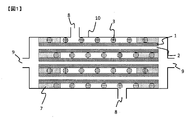
- FIG. 1 shows a schematic cross-sectional view of one aspect of the fluid separation membrane module of the present invention.
- FIG. 1 is a schematic cross-sectional view of a module containing a hollow thread-shaped fluid separation membrane, including an inflow port of the fluid to be separated.
- the module of the present invention includes a fluid separation membrane and a spacer. That is, in the module of the present invention, the fluid separation membrane 1 and the spacer 3 are housed in the vessel 10 having the outflow port 8 of the fluid to be separated.
- the fluid separation membrane 1 of FIG. 1 has a hollow portion 2.
- the fluid separation membrane is fixed at the potting site.
- the fluid separation membranes 1 bundled in parallel in FIG. 1 have both ends fixed to each other (potting) at the potting portion 7 and fixed to the vessel 10.
- the fluid separation membrane 1 penetrates the potting portion 7 and is connected to an external flow path (a flow path for recovering the fluid that has passed through the fluid separation membrane), which is not shown, from the outlet 9 of the permeated fluid of the vessel 10. Will be done.
- the module of the present invention is characterized in that the bundle L can be contracted in the circumferential direction even though the tensile elastic modulus of the fluid separation membrane is 1 GPa or more.
- a bundle of fluid separation membranes having a tensile elasticity of 1 GPa or more has poor contractility in the circumferential direction.
- the module of the present invention imparts contractility in the circumferential direction to the bundle L by accommodating a spacer having contractility together with the fluid separation film, and improves workability when storing the bundle L in the element casing. Damage to the fluid separation membrane due to stress concentration in the circumferential direction can be suppressed.
- the state in which the bundle L has contractility in the circumferential direction means a state in which the outer diameter of the bundle L becomes smaller when an external force such as purging the bundle L is applied in the circumferential direction of the bundle L.
- the external force referred to here represents an external force within a range in which the fluid separation membrane is not damaged.
- At least a part of the spacer has a bulk high compression ratio (hereinafter, may be referred to as “B c ”) measured by the JIS L 1013 (2010) B method of 10% or more and 95%.
- B c a bulk high compression ratio measured by the JIS L 1013 (2010) B method of 10% or more and 95%.
- the following fibers or rods When B c is 10% or more, the bundle L can be contracted by applying an external force.
- B c is preferably 20% or more, and more preferably 50% or more.
- B c is 95% or less, deformation of the fluid separation membrane in the vicinity of the spacer when the bundle L is contracted can be suppressed, so that damage to the membrane can be suppressed.
- B c is preferably 90% or less, more preferably 80% or less.
- the fiber or rod as a spacer preferably has a bulk high compressive elastic modulus (hereinafter, may be referred to as “ Be ”) measured by the JIS L 1013 (2010) B method of 30% or more and 100% or less. ..
- Be a bulk high compressive elastic modulus measured by the JIS L 1013 (2010) B method of 30% or more and 100% or less.
- Be is preferably 40% or more, and more preferably 50% or more.
- the upper limit of Be is not particularly limited, but is preferably 100% or less.
- At least a part of the spacer is a film having a compressibility measured by JIS L 1096 (2010) (hereinafter, may be referred to as “ Cr ”) of 10% or more and 95% or less.
- Cr a compressibility measured by JIS L 1096 (2010)
- the Cr is preferably 20% or more, more preferably 50% or more.
- Cr is 95% or less, deformation of the fluid separation membrane in the vicinity of the spacer when the bundle L is contracted can be suppressed, so that damage to the membrane can be suppressed.
- Cr is preferably 90% or less, more preferably 80% or less.
- the film, non-woven fabric, woven fabric, and knitted fabric as spacers preferably have a compressive elastic modulus (hereinafter, may be referred to as “Ce”) measured by JIS L 1096 (2010) of 30% or more and 100% or less. ..
- Ce compressive elastic modulus
- JIS L 1096 (2010) a force for restoring the outer diameter of the bundle L works when the external force for contracting the bundle L is removed.
- Ce is preferably 40% or more, more preferably 50% or more.
- the upper limit of Ce is not particularly limited, but is preferably 100% or less.
- At least a part of the spacer has a deformation strength (hereinafter, may be referred to as “ ⁇ 10% ”) measured by JIS Z 8844 (2019) of 0.1 kPa or more and 100 kPa or less. It is a particle.
- ⁇ 10% is 0.1 kPa or more, the movement of the fluid separation membrane in the vicinity of the spacer when the bundle L is contracted can be suppressed, so that the damage to the membrane can be suppressed.
- ⁇ 10% is preferably 1 kPa or more, and more preferably 5 kPa or more.
- the bundle L can be contracted by applying an external force.
- ⁇ 10% is preferably 50 kPa or less, and more preferably 10 kPa or less.
- the particles as spacers preferably have a fracture strength (hereinafter, may be referred to as “ ⁇ F ”) measured by JIS Z 8844 (2019) of 2 times or more and 10000 times or less of ⁇ 10% .
- ⁇ F fracture strength measured by JIS Z 8844 (2019) of 2 times or more and 10000 times or less of ⁇ 10% .
- ⁇ F is more than twice ⁇ 10%
- a force for restoring the outer diameter of the bundle L works when the external force for contracting the bundle L is removed.
- ⁇ F is preferably 10 times or more of ⁇ 10% , and more preferably 100 times or more.
- the upper limit of ⁇ F is not particularly limited, but is preferably 10000 times or less of ⁇ 10% .
- the bundle L is a bundle of all the fluid separation membranes and spacers in the module, it is preferable that the circumference of the bundle L satisfies the above formula 1.
- the bundle L is a bundle of all the fluid separation membranes 1 and the spacer 3 in FIG. 1.
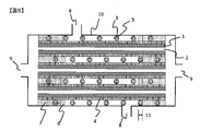
- FIG. 2 shows a schematic diagram of one aspect of a method of measuring the circumference of the outer circumference of the bundle L when the measuring thread is wound once in a direction orthogonal to the long axis of the fluid separation membrane.
- the measurement yarn means a false-twisted polyethylene terephthalate yarn having a total fineness of 3000 dtex and 480 filaments.
- the circumference of the bundle L of the present invention is measured using a measuring thread. That is, in the bundle L; 13 in FIG. 2, the measuring thread 14 is wound around the outer circumference of the bundle L in a direction orthogonal to the long axis of the fluid separation membrane. One end of the measuring thread 14 is fixed, and the weight 15 is fixed to the other end.
- the circumference of the bundle L is the length of the portion around which the measuring thread is wound. That is, in the circumference 16 of the bundle L; 13 in FIG. 2, after the start point and the end point at which the measurement thread 14 goes around the bundle L; 13 are set to points A and B, the bundle L is removed and the measurement thread is straightened. It can be expressed by the distance between points A and B.
- the circumference of the bundle L when the measurement thread is pulled with a force of 5 N / m with respect to the circumference of the bundle L is L 1
- the measurement thread is with respect to the circumference of the bundle L.
- L 2 / L 1 is 0.50 or more and 0.95 or less.
- L 2 / L 1 is 0.50 or more
- the ratio of the fluid separation membrane contained in the bundle L increases, so that the membrane area per module unit volume can be increased.
- L 2 / L 1 is more preferably 0.60 or more, and further preferably 0.75 or more.
- L 2 / L 1 is 0.95 or less, the bundle L is imparted with contractility in the circumferential direction, so that damage to the fluid separation membrane when the bundle L is housed in the module is suppressed.
- L 2 / L 1 is more preferably 0.90 or less, and even more preferably 0.85 or less.
- the length when a load of 5 N is applied in the fiber axis direction is L 3
- the length when a load of 50 N is applied in the fiber axis direction is L 4
- L 4 / L Use a measuring thread in which 3 is 1.05 or less.
- the mixed gas and mixed liquid to be separated by the module of the present invention are not particularly limited, but for example, a carbon dioxide separation / storage system from exhaust gas of a power plant, a blast furnace, etc., and a gas in a coal gasification combined power generation. Examples include removal of sulfur components from the converted fuel gas, purification of biogas and natural gas, and purification of hydrogen from organic hydride. That is, in the module of the present invention, the fluid separation membrane is preferably a gas separation membrane.
- the cross-sectional shape of the vessel is preferably elliptical or circular, and more preferably circular, from the viewpoint of improving the pressure resistance of the vessel.
- the cross section of the vessel means the cross section of the vessel perpendicular to the length direction of the fluid separation membrane.
- the material of the vessel include metal, resin, fiber reinforced plastic (FRP), and the like, which can be appropriately selected depending on the environment of the installation location and the situation in which the vessel is used. In applications where pressure resistance and heat resistance are required, a metal having both strength and formability is preferable, and stainless steel or the like is more preferable.
- the outflow port of the fluid to be separated which is arranged in the vessel, has a function of guiding the fluid to be separated to the fluid separation membrane.
- the fluid separation membrane When the fluid separation membrane is used in the total volume filtration method, it is sufficient to have one inflow port of the fluid to be separated, and when it is used in the cross flow filtration method, the outflow port of the fluid to be separated is combined. It is preferable to have two or more places. There may be a plurality of outflow ports of the fluid to be separated as long as the mechanical strength of the vessel is maintained. In this case, it is preferable to dispose a cloth such as mesh or felt between the outflow port and the fluid separation membrane within a range that does not obstruct the passage of the fluid, and it is effective in diffusing the fluid and protecting the fluid separation membrane.
- a method of fixing the fluid separation membrane to the vessel a method of directly fixing the fluid separation membrane to the inner surface of the vessel with a potting material, or a separation membrane element in which a plurality of fluid separation membranes are fixed by the potting material is used.
- Examples thereof include a method of fixing in the vessel via an adapter or the like (for example, an O-ring or the like) capable of ensuring liquidtightness or airtightness. Since only the separation membrane element can be replaced when the performance of the separation membrane element deteriorates over time, it is preferable to fix the separation membrane element in the vessel via an adapter or the like.
- the potting portion of the module or the separation membrane element may be one place or a plurality of places, but is omitted from the viewpoint of sufficiently fixing the position of the fluid separation membrane and maintaining the effective surface area of the fluid separation membrane. It is preferable to fix the two ends of the plurality of fluid separation membranes bundled in a straight line with a potting material. Further, both ends of the fluid separation membrane may be fixed with a potting material at one place in a state where a plurality of bundled fluid separation membranes are bent into a U shape, or only one end of the fluid separation membrane is fixed with the potting material. The other end may be sealed by means other than the potting material.
- the separation membrane element of the present invention may have a casing (hereinafter referred to as "element casing") different from the vessel.
- the element casing preferably has an outflow port for the fluid to be separated.
- the shape of the element casing is not particularly limited as long as it does not interfere with the storage in the vessel. Examples of the material of the element casing include metal, resin, fiber reinforced plastic (FRP) and the like, which can be appropriately selected depending on the situation in which the element casing is used.
- Resin is preferable because it has high followability to the curing shrinkage of the potting material, and polyphenylene sulfide, polytetrafluoroethylene, polyethylene, polypropylene, polyether ether ketone, polyphenylene ether, and polyether because it has both moldability and chemical resistance. Idyl, polyamide-imide and polysulfone are more preferred.
- the inner diameter of the element casing is preferably L 2 / ⁇ or more and 1.5 L 1 / ⁇ or less.
- the inner diameter of the element casing is more preferably (L 1 + L 2) / 2 ⁇ or more, and further preferably L 1 / ⁇ or more.
- the inner diameter of the element casing is 1.5 L 1 / ⁇ or less, the film area per element unit volume can be increased.
- the inner diameter of the element casing is more preferably 1.2 L 1 / ⁇ or less, and further preferably 1.1 L 1 / ⁇ or less.
- the preferable inner diameter of the element casing is the preferred inner diameter of the vessel.
- the module of the present invention may have a central pipe or the like in the element casing.
- it can be regarded as a bundle L including the central pipe and the like.
- the potting material examples include a thermoplastic resin and a thermosetting resin. Further, other additives may be contained.
- thermoplastic resin used as the potting material examples include polyethylene, polyether sulfone, polystyrene, polyphenylene sulfide, polyarylate, polyester, liquid crystal polyester, polyamide, polymethylmethacrylate and the like.
- thermosetting resin examples include epoxy resin, unsaturated polyester resin, urethane resin, urea resin, phenol resin, melamine resin, silicone resin and the like. Two or more of these may be used. Among these, epoxy resin and urethane resin are preferable from the viewpoint of balance of moldability, curing time, adhesiveness, hardness and the like.
- additives preferably used in potting materials include fillers, surfactants, silane coupling agents, rubber components and the like.
- the filler include silica, talc, zeolite, calcium hydroxide, calcium carbonate and the like, which have effects such as suppression of curing heat generation, strength improvement and thickening.
- the surfactant and the silane coupling agent have the effects of improving the handleability when the potting material is mixed and improving the infiltration property between the carbon films for fluid separation when the potting material is injected.
- the rubber component has the effect of improving the toughness of the cured and molded potting material.
- the rubber component may be contained in the form of rubber particles.
- the fluid separation membrane is a membrane in which the permeability of a specific component (permeable component) contained in the fluid to be separated is higher than that of other components (non-permeable component).
- the shape of the fluid separation membrane is not particularly limited and may be a flat membrane or a hollow fiber membrane. However, when the separation membrane module is used, the membrane area per module unit volume tends to be large, so that the fluid is fluid.
- the separation membrane is preferably a hollow fiber membrane.
- the inner diameter of the hollow fiber membrane is preferably 10 ⁇ m or more and 2,000 ⁇ m or less. By setting the inner diameter of the hollow fiber membrane to 10 ⁇ m or more, the permeability of the fluid can be improved.
- the inner diameter of the hollow fiber membrane is more preferably 20 ⁇ m or more, further preferably 50 ⁇ m or more.
- the outer diameter of the hollow fiber membrane can be reduced, so that the membrane area of the fluid separation membrane per unit volume in the case of a fluid separation membrane module can be increased. Can be done.
- the inner diameter of the fluid separation membrane is more preferably 1,000 ⁇ m or less, further preferably 500 ⁇ m or less.
- the fluid separation membrane examples include a zeolite membrane, a metal-organic framework (MOF) membrane, an inorganic membrane such as a carbon membrane, and a polymer membrane.
- MOF metal-organic framework
- the fluid separation membrane module is preferably an inorganic membrane having excellent heat resistance and chemical resistance, and may be a zeolite membrane or a carbon membrane. preferable. Above all, a carbon film is more preferable.
- Zeolite membranes suitable as fluid separation membranes include aluminosilicates, for example, membranes made of NaX type (FAU), ZSM-5, MOR, silicalite, A type and the like. Two or more of these may be used. Zeolites are preferably those having a Si / Al ratio similar to that of the zeolite that is secondarily grown by a hydrothermal synthesis reaction.
- Suitable MOF membranes as fluid separation membranes include, for example, Cu-BTC, MOF-5, IRMOF-3, MIL-47, MIL-53, MIL-96, MMOF, SIM-1, ZIF-7, ZIF-8. , ZIF-22, ZIF-69, ZIF-90 and the like. Two or more of these may be used.
- Suitable carbon films for the fluid separation film include, for example, polyphenylene oxide, polyvinyl alcohol, polyacrylonitrile, phenol resin, total aromatic polyester, unsaturated polyester resin, alkyd resin, melamine resin, urea resin, polyimide resin, and diallyl phthalate resin. , A film obtained by carbonizing a lignin resin, a urethane resin, or the like. Two or more of these may be used.
- Suitable polymer films for the fluid separation film include, for example, aromatic polyimide, cellulose acetate, polysulfone, aromatic polyamide, polyetherimide, polyethersulfone, polyacrylonitrile, polyphenylene sulfide, polyether ether ketone, polytetrafluoroethylene.
- Polyfluoride vinylidene poly (1-trimethylsilylpropin), polydimethylsiloxane, polyvinyltrimethylsilane, poly (4-methylpentene), ethylcellulose, natural rubber, poly (2,6-dimethyloxide phenylene), low density polyethylene, Examples thereof include a film made of high-density polyethylene, styrene, polyethylmethacrylate, polycarbonate, polyester, aliphatic polyamide, polymethylmethacrylate, polyvinyl alcohol, silicone and the like. Two or more of these may be used.
- Nanoparticles and the like can be added to the fluid separation membrane in order to improve the permeability of the permeable component.
- nanoparticles include silica, titania, zeolite, metal oxide, MOF, carbon nanotube (CNT) and the like.
- the fluid separation membrane of the present invention may include a support.
- the support is arranged only on one surface of the fluid separation membrane.
- the support examples include porous inorganic materials such as alumina, silica, cordierite, zirconia, titania, bicole glass, zeolite, magnesia, and sintered metal, polysulfone, polyethersulfone, polyamide, polyester, and cellulose-based polymers.
- Examples of the carbonizable resin include polyphenylene oxide, polyvinyl alcohol, polyacrylonitrile, phenol resin, total aromatic polyester, unsaturated polyester resin, alkyd resin, melamine resin, urea resin, polyimide resin, diallyl phthalate resin, lignin resin, and urethane. Examples include resin. Two or more of these may be used.
- the fluid separation membrane of the present invention has a coating layer (hereinafter referred to as coating layer 1) on at least a part of the surface thereof.
- coating layer 1 it is more preferable that the coating layer 1 is arranged only on one surface of the fluid separation membrane.
- the coating layer 1 is a layer that covers at least a part of the surface of the fluid separation membrane. Can be coated to improve separation selectivity.
- the coating layer 1 examples include a layer containing at least one compound selected from the group consisting of polyolefin, fluororesin, polystyrene, silicone, microporous polymer (PIM), phenol resin, and urethane resin. Since it is easy to coat the surface of the fluid separation membrane, it is more preferable to contain at least one compound selected from the group consisting of silicone and PIM.
- the abundance ratio of the above compound contained in the coating layer 1 is preferably 20 wt% or more and 100 wt% or less with respect to the total weight of the coating layer 1 of 100 wt%.
- the abundance ratio of the compound contained in the coating layer 1 is more preferably 50 wt% or more, further preferably 80 wt% or more.
- polyolefin suitable as the compound in the coating layer 1 examples include polyethylene, polypropylene, polymethylpentene and the like.
- fluororesin suitable as the compound in the coating layer 1 examples include tetrafluoroethylene and the like.
- silicone suitable as the compound in the coating layer 1 examples include polydimethylsiloxane.
- the phenol resin suitable as the compound in the coating layer 1 is a resin obtained by reacting phenols with aldehydes, and for example, a water-soluble phenol resin solution in which phenols and aldehydes are polycondensed and a water-soluble phenol resin solution. It is a phenolic resin formed by an opposite diffusion reaction with a hardening gas.
- the above-mentioned water-soluble phenol resin solution contains, for example, a phenol resin obtained by reacting phenols including phenol, cresol, resorcinol, bisphenol A, and other substituted phenols with an aldehyde compound or the like under an alkaline catalyst. Etc. are included.
- the curing gas for the water-soluble phenolic resin solution examples include acidic gases such as carbon dioxide, hydrogen sulfide, sulfur oxides, nitrogen oxides, inorganic acids (hydrogen chloride and the like), organic acids (carboxylic acids and the like), and the like.
- acidic gases such as carbon dioxide, hydrogen sulfide, sulfur oxides, nitrogen oxides, inorganic acids (hydrogen chloride and the like), organic acids (carboxylic acids and the like), and the like.
- examples thereof include a gas that produces an acid by reacting with a water-soluble phenol resin solution such as an ester (organic ester, inorganic ester, etc.).
- a plurality of curing gases may be mixed and used, or a mixed gas with an inert gas may be used.
- the urethane resin suitable as the compound in the coating layer 1 is a resin obtained by a double addition reaction of a polyol compound and a polyisocyanate compound.
- phenol resins obtained by reacting phenols including phenol, cresol, resorcinol, bisphenol A, and other substituted phenols with aldehyde compounds and the like under an alkaline catalyst. Will be.
- the polyisocyanate compound is an organic compound having two or more isocyanates in one molecule, and includes aliphatic and aromatic polyisocyanate compounds, and modified products thereof.
- aliphatic polyisocyanate include hexamethylene diisocyanate, isophorone diisocyanate, dicyclohexylmethane diisocyanate, methylcyclohexanediisocyanate and the like
- aromatic polyisocyanate include toluene diisocyanate, diphenylmethane diisocyanate, polypeptide diphenylmethane diisocyanate and the like.
- these modified products include carbodiimide modified products and prepolymer modified products.
- Examples of the amine gas used for forming the urethane resin include triethylamine, dimethylethylamine, dimethylisopropylamine and the like.
- the thickness of the coating layer 1 is not particularly limited, but is preferably 0.1 ⁇ m or more and 100 ⁇ m or less. When the thickness of the coating layer 1 is 0.1 ⁇ m or more, the portion of the surface of the fluid separation film to be coated can be reliably coated.
- the thickness of the coating layer 1 is more preferably 1 ⁇ m or more, further preferably 2 ⁇ m or more. On the other hand, when the thickness of the coating layer 1 is 100 ⁇ m or less, the filling rate of the fluid separation membrane in the fluid separation membrane module and the permeability of the fluid to be separated can be maintained.
- the thickness of the coating layer 1 is more preferably 50 ⁇ m or less, further preferably 20 ⁇ m or less.
- the thickness of the coating layer 1 can be measured, for example, by observing the cross section of the fluid separation membrane having the coating layer 1 with a transmission electron microscope (SEM) or the like.
- the cross section of the fluid separation membrane having the coating layer 1 is formed by embedding the fluid separation membrane having the coating layer 1 in a resin or the like that can be distinguished from the coating layer 1 at the time of observation, and cutting in a direction perpendicular to the depth direction of the coating layer 1. Obtained by doing.
- the tensile elastic modulus of the fluid separation membrane is preferably 1.5 GPa or more.
- the tensile elastic modulus of the fluid separation membrane is more preferably 2.0 GPa or more, further preferably 3.0 GPa or more.
- the upper limit of the tensile elastic modulus of the fluid separation membrane is not particularly limited, but is preferably 500 GPa or less, and when it is 500 GPa or less, damage during transportation or module operation can be suppressed.
- the tensile elastic modulus is more preferably 300 GPa or less, and further preferably 100 GPa or less.
- the tensile elastic modulus of the fluid separation membrane can be measured by a tensile test.
- the tensile elastic modulus of the fluid separation membrane having the support or the coating layer 1 is regarded as the tensile elastic modulus of the fluid separation membrane.
- the fluid separation membrane preferably has a bending radius of 100 cm or less.
- the bending radius of the fluid separation membrane is 100 cm or less, it is possible to suppress the breakage of the fluid separation membrane during the production or operation of the module.
- the bending radius is more preferably 10 cm or less, further preferably 5 cm or less.
- the lower limit of the bending radius of the fluid separation membrane is not particularly limited, but 0.1 cm or more is preferable, and 0.1 cm or more improves the morphological stability when the fluid separation membrane is handled as a bundle. Module manufacturing efficiency is improved.
- the bending radius is more preferably 0.2 cm or more, and further preferably 0.5 cm or more.
- the bending radius of the fluid separation film is obtained from the radius of the cylinder in which the fluid separation film is sampled from the module by 10 cm or more and the sampled fluid separation film is wound 360 ° or more along the normal direction of the cylinder so that the fluid separation film does not break. be able to.
- the bending radius of the fluid separation film is 1.5 cm or more, the angle at which the sampled fluid separation film is wound along the normal direction of the cylinder is appropriately reduced for evaluation, and the radius of the cylinder at which the fluid separation film does not break is determined. , Can be regarded as the bending radius of the fluid separation film.
- the bending radius of the fluid separation membrane having the support or the coating layer 1 is regarded as the bending radius of the fluid separation membrane.
- the water permeability of the fluid separation membrane of the present invention is preferably 0 ⁇ L / hr / m 2 / Pa or more and 100 ⁇ L / hr / m 2 / Pa or less.
- a fluid separation membrane having a water permeability of 100 ⁇ L / hr / m 2 / Pa or less can be suitably used as a gas separation membrane because the pore diameter of the separation functional layer is small.
- the water permeability of the fluid separation membrane is more preferably 10 ⁇ L / hr / m 2 / Pa or less, further preferably 1 ⁇ L / hr / m 2 / Pa or less.
- the permeability of the fluid separation membrane can be calculated by the following formula 3 from the amount of permeated water recovered from the outflow port of the permeation fluid of the module when pure water is supplied from the outflow port of the fluid to be separated of the module. can.
- Qw represents the amount of permeated water ( ⁇ L)
- P represents the pressure of the feed water (Pa)
- T represents the water permeation time (hr)
- A represents the fluid separation membrane having the coating layer 1.
- the water permeability of the fluid separation membrane having the support or the coating layer 1 is regarded as the water permeability of the fluid separation membrane.
- the spacer is arranged in the module together with the fluid separation membrane, and has the effect of imparting contractility in the circumferential direction to the bundle L, which is a bundle of all the fluid separation membranes and the spacer in the module.
- the arrangement of the fluid separation membrane and the spacer in the bundle L is not particularly limited, and the fluid separation membrane may be arranged around the spacer, or the spacer may be arranged around the bundle of the fluid separation membrane, and the fluid may be arranged. Spacers may be arranged between the separation membranes. The arrangement may be a combination of these. It is more preferable that at least a part of the spacer is arranged between the fluid separation membranes because the passage of the fluid to be separated becomes uniform.
- the spacer is not particularly limited, but is preferably selected from the group consisting of films, non-woven fabrics, woven fabrics, knitted fabrics, fibers, rods, and particles. Two or more of these may be combined. Since it is easy to place between the fluid separation membranes, the spacer when the fluid separation membrane is a flat membrane is preferably a film, a non-woven fabric, a woven fabric, or a knitted fabric, and when the fluid separation membrane is a hollow fiber membrane, the spacer is It is preferably a fiber and a rod.
- spacer examples include polyester, nylon, polyolefin, fluororesin, polyacetal, thermoplastic elastomer, metal oxide and the like. Two or more of these may be used.
- the spacer When the spacer is a fiber, the spacer may be a monofilament or a multifilament, but a multifilament is preferable because it is flexible and has excellent handleability. Further, it is more preferable to use false twisted yarn as the spacer because it is bulky and it is easy to secure the distance between the fluid separation membranes. As the false twisted yarn suitable as a spacer, polyester yarn and nylon yarn are preferable because false twisting is easy.
- the present invention also has an embodiment in which the spacer spirally covers the circumference of one or more fluid separation membranes. Is one of the preferred embodiments of.
- FIG. 3 and 4 show a schematic diagram of one aspect in which a spacer spirally covers the periphery of one or more fluid separation membranes.
- FIG. 3 is a schematic view of one embodiment in which one spacer 3 is spirally covered with one fluid separation membrane 1 at intervals of pitch 12, and
- FIG. 4 is a schematic view of two fluid separation membranes. It is a schematic diagram of one aspect in which two spacers 3 are spirally covered with an interval of pitch 12 with respect to 1.
- the coating around the fluid separation membrane by the spacer may be a single covering in which the spacer is wound once or a double covering in which the spacer is doublely wound around the fluid separation membrane.
- multi-stage covering in which the second spacer is further spirally wound with respect to a plurality of fluid separation membranes in which the first spacer is spirally wound is also one of the preferred embodiments of the present invention.
- the first spacer and one or more fluid separation membranes wound by the first spacer are collectively referred to as a bundle S
- the second spacer and one or more bundles S wound by the second spacer are collectively referred to as a bundle M.
- a plurality of fluid separation membranes, a bundle S, and a bundle M may be collectively formed as a bundle L.
- the occupied volume of the second spacer in the bundle M is smaller than the occupied volume of the first spacer in the bundle M. Since the occupied volume of the second spacer in the bundle M is smaller than the occupied volume of the first spacer in the bundle M, it is easy to secure the distance between the fluid separation membranes. Therefore, when the viscosity of the fluid to be separated is high. It can be suitably used even when the fluid to be separated has a large amount of agglomerating components.
- the ratio of the occupied volume of the first spacer to the bundle M to the occupied volume of the second spacer in the bundle M (that is, "the occupied volume of the first spacer in the bundle M" / "the second occupied volume in the bundle M”.
- the occupied volume of the spacer is more preferably 1.2 or more, and further preferably 1.5 or more.
- the upper limit of the ratio of the occupied volume of the first spacer to the occupied volume of the bundle M to the occupied volume of the second spacer in the bundle M is not particularly limited, but is preferably 100 or less, and the module volume is preferably 100 or less.
- the membrane area of the fluid separation membrane can be secured.
- the ratio of the occupied volume of the first spacer to the occupied volume of the bundle M to the occupied volume of the second spacer in the bundle M is more preferably 50 or less, and further preferably 10 or less.
- the occupied volume of the second spacer in the bundle M is larger than the occupied volume of the first spacer in the bundle M. Since the occupied volume of the second spacer in the bundle M is larger than the occupied volume of the first spacer in the bundle M, the fluid separation membranes in the bundle M are close to each other, so that the tensile load of the bundle M is improved. And the handleability is improved.
- the ratio of the occupied volume of the second spacer to the bundle M to the occupied volume of the first spacer in the bundle M that is, "the occupied volume of the second spacer in the bundle M" / "the first occupied in the bundle M".
- the occupied volume of the spacer is more preferably 1.2 or more, and further preferably 1.5 or more.
- the upper limit of the ratio of the occupied volume of the second spacer to the occupied volume of the bundle M to the occupied volume of the first spacer in the bundle M is not particularly limited, but is preferably 100 or less, and the module volume is preferably 100 or less.
- the membrane area of the fluid separation membrane can be secured.
- the ratio of the occupied volume of the second spacer to the occupied volume of the bundle M to the occupied volume of the first spacer in the bundle M is more preferably 50 or less, and further preferably 10 or less.
- the occupied volume of the spacer is adjusted so that the first spacer or the second spacer collected from the bundle M of a certain length is stored in a cylindrical container and the weight is 0.15 g / cm 2 with respect to the cross-sectional area of the cylinder.
- the height L 0 of the spacer after placing the circular plate on the spacer and leaving it for 1 minute can be measured and calculated from the following formula 4.
- the dispersibility of the fluid separation film in the module can be evaluated.
- the area of the Voronoi region is the area of the region partitioned by the Voronoi division.
- Voronoi division is a method of dividing a plane surrounded by generatrix, which has a plurality of generatrix, by a perpendicular bisector between adjacent generatrix and an intermediate line between the generatrix and the generatrix adjacent to each other. That is, the higher the dispersibility of the fluid separation membrane in the module, the more uniform the area of the Voronoi region of the fluid separation membrane.
- the area of the Voronoi region of the fluid separation film in the cross section perpendicular to the longitudinal direction of the module satisfies the following formula 2.
- S 0 ⁇ r ⁇ 50 / S 50 ⁇ r ⁇ 100 is larger than 0.5, the number of fluid separation membranes housed in the outer edge of the module having a large volume increases, so that the membrane area per module unit volume is increased. be able to.
- S 0 ⁇ r ⁇ 50 / S 50 ⁇ r ⁇ 100 is more preferably 1 or more, and further preferably 1.5 or more.
- S 0 ⁇ r ⁇ 50 / S 50 ⁇ r ⁇ 100 is smaller than 10, the gap between the bundle L and the element casing and the like can be reduced, and the short path of the fluid to be separated can be suppressed.
- S 0 ⁇ r ⁇ 50 / S 50 ⁇ r ⁇ 100 is more preferably 5 or less, and further preferably 2 or less.
- Equation 2 [In the equation, S 0 ⁇ r ⁇ 50 is the area of the boronoy region of the fluid separation membrane in the region where the distance from the center of the fluid separation membrane storage region is 0% or more and less than 50% of the radius of the fluid separation membrane storage region. Representing an average value, S 50 ⁇ r ⁇ 100 is the area of the boronoy region of the fluid separation membrane in the region where the distance from the center of the fluid separation membrane storage region is more than 50% and 100% or less of the radius of the fluid separation membrane storage region. Represents the average value.
- the cross section perpendicular to the longitudinal direction of the module is perpendicular to the longitudinal direction of the fluid separation membrane of the module after injecting thermosetting resin from the outflow port of the fluid to be separated of the module to fix the position of the fluid separation membrane in the module. Obtained by cutting on a surface.
- the area of the Voronoi region of the fluid separation membrane can be obtained by image analysis of the above cross section. More specifically, by performing Voronoi division with the center of gravity of each fluid separation membrane in the above cross-sectional image as the generatrix and the boundary line of the fluid separation membrane storage region as the generatrix, the area of the Voronoi region can be determined for each fluid separation membrane. Can be calculated.
- Examples of the boundary line of the fluid separation membrane storage region include the inner surface of the element casing or vessel, and the outer surface of the central pipe or the like.
- S 0 ⁇ r ⁇ 50 is the boronoy region in the fluid separation membrane in which the boronoy region is included in the region where the distance from the center of the fluid separation membrane storage region is 0% or more and less than 50% of the radius of the fluid separation membrane storage region.
- S 50 ⁇ r ⁇ 100 is a fluid in which the boronoy region is included in a region where the distance from the center of the fluid separation membrane storage region is more than 50% and 100% or less of the radius of the fluid separation membrane storage region.
- a coating layer (hereinafter referred to as coating layer 2) may be provided on the surface of the spacer.
- the presence of the coating layer 2 on at least a part of the surface of the spacer can control the friction between the fluid separation membrane and the coating layer 2, reduce the friction and prevent damage to the fluid separation membrane due to stress concentration. Friction can be increased to fix the position of the spacer.
- at least a part of the spacer is arranged between the membranes of the fluid separation membrane, it is possible to uniformly pass the fluid to be separated by suppressing the displacement of the spacer during the production or operation of the separation membrane module. can.
- damage to the surface of the fluid separation membrane due to friction between the fluid separation membrane and the spacer can be further suppressed.
- the above-mentioned coating layer 1 may be provided on at least a part of the surface of the fluid separation membrane.
- the coating layer 2 may have the same composition as the coating layer 1 or may have a different composition. Further, the coating layer 1 and the coating layer 2 may have a clear boundary or may be integrated.
- the fluid separation membrane is fixed at the potting portion, and a coating layer (hereinafter referred to as coating layer 3) may be provided on the surface of the potting portion on the inner side of the fluid separation membrane module.
- a coating layer hereinafter referred to as coating layer 3
- the coating layer 3 is preferably an elastomer. Since the coating layer 3 is an elastomer, the vibration of the fluid separation membrane in the vicinity of the potting portion during the production or operation of the module is reduced, and damage to the fluid separation membrane can be suppressed.
- Examples of the elastomer suitable for the coating layer 3 include a thermosetting elastomer and a thermoplastic elastomer, which are appropriately selected according to the operating conditions of the module.
- Examples of the thermosetting elastomer include vulcanized rubber, urethane rubber, silicone rubber, and fluororubber.
- Examples of the thermoplastic elastomer include polystyrene-based elastomers, olefin-based elastomers, polyvinyl chloride-based elastomers, polyurethane-based elastomers, polyester-based elastomers, polyamide-based elastomers, and acrylic-based elastomers.
- the coating layer 3 may have the same composition as the coating layer 1 and the coating layer 2, or may have a different composition. Further, the coating layer 3, the coating layer 1 and the coating layer 2 may have a clear boundary or may be integrated. From the viewpoint of workability at the time of manufacturing the fluid separation membrane module, it is preferable that the coating layer 1, the coating layer 2, and the coating layer 3 have the same composition.
- the thickness of the coating layer 3 is preferably 10 ⁇ m or more and 50,000 ⁇ m or less. When the thickness of the coating layer 3 is 10 ⁇ m or more, it is possible to reduce the vibration of the fluid separation membrane in the vicinity of the potting portion during operation of the fluid separation membrane module.
- the thickness of the coating layer 3 is more preferably 100 ⁇ m or more, further preferably 1000 ⁇ m or more. On the other hand, when the thickness of the coating layer 3 is 50,000 ⁇ m or less, the surface area of the fluid separation membrane can be sufficiently secured.
- the thickness of the coating layer 3 is more preferably 20000 ⁇ m or less, further preferably 10,000 ⁇ m or less.
- the thickness of the coating layer 3 can be measured, for example, by observing the cross section of the potting portion having the coating layer 3 with a transmission electron microscope (SEM) or the like.
- the cross section of the potting portion having the coating layer 3 is formed by embedding the potting portion having the coating layer 3 with a resin or the like that can be distinguished from the coating layer 3 at the time of observation, and cutting in a direction perpendicular to the depth direction of the coating layer 3. Obtained at.
- the composition of the coating layer can be analyzed by elemental analysis of the coating layer or the like.
- FIG. 5 shows a schematic cross-sectional view of another aspect of the fluid separation membrane module of the present invention.
- FIG. 5 is a schematic cross-sectional view of a module containing a hollow thread-shaped fluid separation membrane and having coating layers 1 to 3 including an inflow port of the fluid to be separated.
- the module of the present invention preferably has a coating layer 1 on at least a part of the surface of the fluid separation membrane. That is, the fluid separation membrane 1 of FIG. 5 has a hollow portion 2 and a coating layer 1; 4 on the surface.
- the module of the present invention preferably has a coating layer 2 on the surface of the spacer. That is, the spacer 3 in FIG. 5 has a coating layer 2; 5 on its surface.
- the fluid separation membrane is fixed at the potting portion, and it is preferable that the coating layer 3 is provided on the surface of the potting portion on the inner side of the fluid separation membrane module.
- the fluid separation membranes 1 bundled in parallel in FIG. 5 have both ends fixed to each other (potting) at the potting portion 7 and fixed to the vessel 10.
- the potting site 7 has a coating layer 3; 6 on the inner surface of the fluid separation membrane module.
- the fluid separation membrane plant of the present invention (hereinafter, may be simply referred to as "plant") is a plant including the fluid separation membrane module of the present invention.
- the plant preferably includes pretreatment equipment, purified fluid recovery equipment, by-product fluid recovery equipment, etc. in addition to the module.
- the pretreatment equipment is equipment for removing impurities from the separation target fluid before separation and adjusting the composition of the separation target fluid before separation.
- the purified fluid recovery facility is a facility for recovering a purified fluid from which unnecessary components have been removed from the fluid to be separated before separation, and further purifying or supplying the purified fluid to a pipeline or the like as necessary.
- the by-product fluid recovery facility is a facility that recovers the by-product fluid removed from the separation target fluid before separation and discharges it after detoxification as an example.
- the module and the pretreatment equipment, the purified fluid recovery equipment, the by-product fluid recovery equipment are connected by pipes, etc., and the fluid to be separated before separation is continuously separated into the purified fluid and the by-product fluid. Is preferable.
- the plant preferably includes a plurality of modules according to the processing amount of the fluid to be separated.
- the plurality of modules may be connected in series to the fluid to be separated, or may be connected in parallel. From the viewpoint of module manufacturing efficiency, the modules are preferably connected in series, and from the viewpoint of being able to partially replace the modules, the modules are preferably connected in parallel.
- a preferred embodiment of the plant of the present invention is an embodiment in which modules are connected in series and modules connected in series are further connected in parallel. By doing so, it is possible to achieve both the merits of connecting modules in series and the merits of connecting modules in parallel.
- the mixed gas and mixed liquid to be separated by the plant of the present invention are not particularly limited, but for example, a carbon dioxide separation / storage system from exhaust gas of a power plant, a blast furnace, etc., and a gas in a coal gasification combined power generation. Examples include removal of sulfur components from the converted fuel gas, purification of biogas and natural gas, and purification of hydrogen from organic hydride. That is, in the plant of the present invention, the fluid separation membrane is preferably a gas separation membrane.
- the purified fluid of the present invention is a fluid purified by the fluid separation membrane module of the present invention.
- the purified fluid may be purified by including another purification step or an additional step before and after the purification step in the module of the present invention, or may be mixed with a purification fluid purified by a different purification step.
- Other purification steps and different purification steps include, for example, distillation, adsorption, absorption and the like.
- component adjustment to be mixed with another fluid can be mentioned.
- the purification fluid of the present invention consumes a small amount of energy required for purification in the module, it can be suitably used in various industrial applications as a purification fluid having a low environmental load.
- a spacer is spirally wound around a fluid separation membrane to form a bundle S, and a bundle L composed of a plurality of bundles S is inserted into an element casing or a vessel, and a potting material is used.
- the case of fixing will be described as an example.
- One fluid separation membrane is used as the core thread, and the spacer is spirally wound to form a bundle S.
- the device for spirally winding the spacer include a covering twisting machine and a double covering twisting machine.
- a plurality of the obtained bundles S are bundled into a bundle L, inserted into the element casing or vessel, and then one end or both ends of the covering carbon film are potted with a potting material.
- a contraction force in the circumferential direction is applied to the end of the bundle L to reduce the outer diameter of the end of the bundle L, and then the bundle L is stored in the element casing or vessel. preferable.
- a potting method for example, a centrifugal potting method in which centrifugal force is used to permeate between fluid separation membranes, and a static potting material in which a fluidized potting material is sent by a metering pump or a head and permeated into a carbon film for fluid separation is allowed to stand.
- a potting method for example, a centrifugal potting method in which centrifugal force is used to permeate between fluid separation membranes, and a static potting material in which a fluidized potting material is sent by a metering pump or a head and permeated into a carbon film for fluid separation is allowed to stand. Examples include the potting method.
- a cap as a pipe joint member to the cut surface of the fluid separation membrane module so that it can be connected to an external flow path (a flow path for collecting the fluid that has passed through the fluid separation membrane, etc.).
- the mixed fluid to be separated by the module of the present invention is not particularly limited, but for example, a carbon dioxide separation / storage system from exhaust gas of a power plant, a blast furnace, etc., and a gasified fuel in a coal gasification combined power generation.
- a carbon dioxide separation / storage system from exhaust gas of a power plant, a blast furnace, etc.
- a gasified fuel in a coal gasification combined power generation examples include removal of sulfur components from gas, purification of biogas and natural gas, and purification of hydrogen from organic hydride.
- both ends of the sampled fluid separation membrane were reinforced with an adhesive by 1 cm, and the reinforced portion was fixed to the chuck of a tensile tester (TENSILON (registered trademark) / RTM-100, manufactured by Toyo Baldwin Co., Ltd.), and the sample length was obtained.
- the tensile elastic modulus (GPa) was measured under the conditions of 80 mm and a tensile speed of 10 mm / min. The measurement was performed 10 times each, and the average value indicated by two significant figures was taken as the tensile elastic modulus of the fluid separation membrane.
- Spacers were sampled from the fluid separation membrane modules of Examples 1 to 6 and Comparative Example 2, and the bulk high compressibility and the bulk high compressibility were measured according to the JIS L 1013 (2010) B method.
- the measurement thread was wound around the outer circumference of the bundle L in a direction orthogonal to the major axis of the fluid separation membrane, and the circumference of the bundle L when the pulling force of the measurement thread was changed was measured.
- the circumferential contractility (L 2 / L 1 ) of the bundle L is the measurement thread with respect to the circumference L 1 of the bundle L when the measurement thread is pulled with a force of 5 N / m with respect to the circumference length of the bundle L.
- thermosetting resin is injected from the outflow port of the fluid to be separated of the acrylic pipe to fix the position of the fluid separation film in the module, and then the vicinity of the center of the longitudinal direction of the module is in the longitudinal direction of the fluid separation film.
- a cross-sectional image was obtained by cutting on a vertical plane. Voronoi division was performed with the center of gravity of each fluid separation film in the obtained cross-sectional image as a generatrix and the inner surface of the acrylic pipe as a generatrix, and the area of the Voronoi region was calculated for each fluid separation film.
- the average value of the area of the boronoy region and the distance from the center of the acrylic pipe in the fluid separation membrane in which the boronoy region is included in the region where the distance from the center of the acrylic pipe is 0% or more and less than 50% of the radius of the acrylic pipe Obtain the average value of the area of the boronoy region in the fluid separation membrane in which the boronoy region is included in the region of more than 50% and 100% or less of the radius of the acrylic pipe, and calculate S 0 ⁇ r ⁇ 50 / S 50 ⁇ r ⁇ 100 . did.
- the bundle M was sampled from the fluid separation membrane modules of Examples 4 and 5, and the first spacer and the second spacer were sampled from the bundle M, respectively.
- the sampled first spacer or second spacer was placed in a cylindrical container, and a circular plate whose weight was adjusted to 0.15 g / cm 2 with respect to the cross-sectional area of the cylinder was placed on the spacer and left for 1 minute.
- the height L 0 of the latter spacer was measured, the occupied volumes of the first spacer and the second spacer were calculated from the following formula 4, and the ratio between the two was calculated.
- Occupied volume of spacer cross section of cylinder x L 0 ... Equation 4 (Water permeability of fluid separation membrane) Pure water of 0.1 MPaG was supplied from the outflow port of the fluid to be separated of the prepared fluid separation membrane module, and the pure water that had passed through the fluid separation membrane was recovered from the outlet of the permeated fluid for 10 minutes. From the amount of pure water recovered, the water permeability of the fluid separation membrane was calculated by the following formula 3.
- Q w represents the amount of permeated water ( ⁇ L)
- P represents the pressure of the feed water (Pa)
- T represents the water permeation time (hr)
- A represents the membrane area (m) of the fluid separation membrane. 2 ) is represented.
- the permeability of the fluid separation membrane was not evaluated for the module in which the breakage of the fluid separation membrane during module fabrication was "Yes".
- Example 4 the bending radius of the fluid separation membrane having the coating layer 1 was obtained by the same measurement. In addition, the bending radius of the fluid separation membrane was not evaluated for the module in which the damage of the fluid separation membrane during module fabrication was "presence".
- the precursor of the obtained porous carbon film was passed through an electric furnace at 250 ° C. and heated in an air atmosphere for 1 hour to perform infusibilization treatment to obtain infusible yarn. Subsequently, the infusible yarn was carbonized at a carbonization temperature of 650 ° C. to obtain a fluid separation membrane of Production Example 1, which is a carbon film for fluid separation having an outer diameter of 300 ⁇ m and an inner diameter of 100 ⁇ m.
- Example 1 A 170 dtex polyester false twisted yarn, which is a spacer, was spirally wound around a core yarn of one fluid separation membrane of Production Example 1 at a pitch of 1 cm.
- the tensile elastic modulus of the fluid separation membrane was 3.2 GPa
- the bulk high compressibility of the spacer was 47.1%
- the bulk high compressibility was 77.9%
- the bundle L was in the circumferential direction.
- Shrinkage (L 2 / L 1 ) is 0.86
- storage of bundle L in element casing is "good”
- no damage to fluid separation membrane during module fabrication dispersibility of fluid separation membrane in cross section (S 0 ⁇ r ⁇ 50 / S 50 ⁇ r ⁇ 100 ) was 1.0
- the water permeability of the fluid separation membrane was 1 ⁇ L / hr / m 2 / Pa or less
- the bending radius was 10 cm or less.
- Example 2 A 170 dtex polyester false twisted yarn, which is a spacer, is spirally wound around one fluid separation membrane of Production Example 1 at a pitch of 1 cm, and a 170 dtex polyester false twisted yarn, which is a spacer, is spirally wound at a pitch of 1 cm. Wrapped in a spiral.
- the tensile elastic modulus of the fluid separation membrane was 3.2 GPa
- the bulk high compressibility of the spacer was 47.1%
- the bulk high compressibility was 77.9%
- the bundle L was in the circumferential direction.
- Shrinkage (L 2 / L 1 ) is 0.68
- storage of bundle L in element casing is "good”
- no damage to fluid separation membrane during module fabrication dispersibility of fluid separation membrane in cross section (S 0 ⁇ r ⁇ 50 / S 50 ⁇ r ⁇ 100 ) was 0.98
- the water permeability of the fluid separation membrane was 1 ⁇ L / hr / m 2 / Pa or less
- the bending radius was 10 cm or less.
- Example 3 A 170 dtex polyester false twisted yarn, which is a spacer, is spirally wound around one fluid separation membrane of Production Example 1 at a pitch of 1 cm, and a 170 dtex polyester false twisted yarn, which is a spacer, is spirally wound at a pitch of 1 cm. Wrapped in a spiral.
- the tensile elastic modulus of the fluid separation membrane was 3.2 GPa
- the bulk high compressibility of the spacer was 47.1%
- the bulk high compressibility was 77.9%
- the bundle L was in the circumferential direction.
- Shrinkage (L 2 / L 1 ) is 0.85
- storage of bundle L in element casing is "good”
- no damage to fluid separation membrane during module fabrication dispersibility of fluid separation membrane in cross section (S 0 ⁇ r ⁇ 50 / S 50 ⁇ r ⁇ 100 ) was 2.0
- the water permeability of the fluid separation membrane was 1 ⁇ L / hr / m 2 / Pa or less
- the bending radius was 10 cm or less.
- Example 4 One fluid separation membrane of Production Example 1 is used as a core yarn, and four fluid separation membranes in which 170 dtex polyester false twisted yarn, which is the first spacer, is spirally wound at a pitch of 1 cm are bundled, and further, a second fluid separation membrane is bundled. A 170 dtex polyester false twisted yarn, which is a spacer, was spirally wound at a pitch of 1 cm.
- the tensile elastic modulus of the fluid separation film was 3.2 GPa
- the bulk high compressibility of the spacer was 47.1%
- the bulk high compressibility was 77.9%
- the bundle L was in the circumferential direction.
- Shrinkage (L 2 / L 1 ) is 0.77
- storage of bundle L in element casing is "good”
- no damage to fluid separation film during module fabrication dispersibility of fluid separation film in cross section (S 0 ⁇ r ⁇ 50 / S 50 ⁇ r ⁇ 100 ) is 1.0
- the ratio of the occupied volume of the first spacer to the occupied volume of the bundle M to the occupied volume of the second spacer in the bundle M is 1.6.
- the water permeability of the fluid separation film was 1 ⁇ L / hr / m 2 / Pa or less
- the bending radius was 10 cm or less.
- Example 5 One fluid separation membrane of Production Example 1 is used as a core yarn, and four fluid separation membranes in which 170 dtex polyester false twisted yarn, which is the first spacer, is spirally wound at a pitch of 5 cm are bundled, and further, a second fluid separation membrane is bundled. A 170 dtex polyester false twisted yarn, which is a spacer, was spirally wound at a pitch of 0.5 cm.
- the tensile elastic modulus of the fluid separation film was 3.2 GPa
- the bulk high compressibility of the spacer was 47.1%
- the bulk high compressibility was 77.9%
- the bundle L was in the circumferential direction.
- Shrinkage (L 2 / L 1 ) is 0.77
- storage of bundle L in element casing is "good”
- no damage to fluid separation film during module fabrication dispersibility of fluid separation film in cross section (S 0 ⁇ r ⁇ 50 / S 50 ⁇ r ⁇ 100 ) is 1.0
- the ratio of the occupied volume of the first spacer to the occupied volume of the bundle M to the occupied volume of the second spacer in the bundle M is 0.2.
- the water permeability of the fluid separation film was 1 ⁇ L / hr / m 2 / Pa or less
- the bending radius was 10 cm or less.
- Example 6 A 170 dtex polyester false twisted yarn, which is a spacer, was spirally wound around a core yarn of one fluid separation membrane of Production Example 1 at a pitch of 1 cm.
- a 10 wt% hexane solution (hereinafter referred to as PDMS solution) of polydimethylsiloxane (Silgard manufactured by Toray DuPont) was injected from the outflow port of the fluid to be separated.
- PDMS solution 10 wt% hexane solution
- the Silkard solution is discharged from the outflow port of the fluid to be separated, and after drying, it is heated in an oven at 70 ° C. for 30 minutes to form coating layers 1 to 3.
- the fluid separation membrane module of Example 6 was obtained.
- the fluid separation membrane module of Example 6 has a coating layer 1, a coating layer 2 and a coating layer 3 made of PDMS which is silicone.
- the tensile elasticity of the fluid separation membrane is 3.6 GPa
- the bulk high compressibility of the spacer is 47.1%
- the bulk high compressive elasticity is 77.9%
- the bundle L is in the circumferential direction.
- Shrinkage (L 2 / L 1 ) is 0.91
- the storage of bundle L in the element casing is "good”
- the fluid separation membrane is not damaged during module fabrication
- the dispersibility of the fluid separation membrane in the cross section is "no".
- Example 7 A 56 dtex polyester false twisted yarn was flat knitted with a weft knitting machine to produce a flat knitted fabric as a spacer having 70 wales per 2.54 cm and 70 courses per 2.54 cm.
- the tensile elasticity of the fluid separation membrane was 3.2 GPa
- the compressibility of the spacer was 52.3%
- the compressibility was 81.2%
- Example 8 Micropearl SP (manufactured by Sekisui Chemical Co., Ltd.), which is a particle, was immersed in a polyethylene glycol solution, drained, and then sprinkled on the surface of the fluid separation membrane of Production Example 1. Subsequently, 100 fluid separation films of Production Example 1 sprinkled with the spacer Micropearl SP were bundled, stored in an acrylic pipe (inner diameter 5 mm) having an outflow port of the fluid to be separated, and using an epoxy resin. Both ends of the acrylic pipe were statically potted one by one. After the epoxy resin was cured, the potting portion at one end was cut with a rotary saw to open the fluid separation membrane, and the fluid separation membrane module of Example 8 was obtained.
- the tensile elasticity of the fluid separation film is 3.2 GPa
- the deformation strength of the spacer is 80 kPa
- the breaking strength is 100 MPa
- the contractility of the bundle L in the circumferential direction (L 2 / L 1 ) is 0.
- the storage capacity of the bundle L in the element casing is "good”
- the damage of the fluid separation film during module fabrication is "no”
- the dispersibility of the fluid separation film in the cross section was 0.79
- the water permeability of the fluid separation film was 1 ⁇ L / hr / m 2 / Pa or less
- the bending radius was 10 cm or less.
- Comparative Example 1 100 fluid separation films of Production Example 1 were bundled and housed in an acrylic pipe (inner diameter 5 mm) having an outflow port of the fluid to be separated, and both ends of the acrylic pipe were statically potted using epoxy resin. After the epoxy resin was cured, the potting portion at one end was cut with a rotary saw to open the fluid separation membrane.
- the tensile elasticity of the fluid separation film was 3.2 GPa
- the circumferential contractility of the bundle L (L 2 / L 1 ) was 0.99
- the storage capacity of the bundle L in the element casing was achieved.
- the damage of the fluid separation film during module fabrication is "yes”
- the dispersibility of the fluid separation film in the cross section (S 0 ⁇ r ⁇ 50 / S 50 ⁇ r ⁇ 100 ) is 0.31
- the bending radius is 0.31. It was 10 cm or less.
- Comparative Example 2 A fluid separation membrane module of Comparative Example 2 was obtained in the same manner as in Example 1 except that a stainless wire having a wire diameter of 0.3 mm was used as a spacer instead of the 170 dtex polyester false twisted yarn.
- the tensile elasticity of the fluid separation film is 3.2 GPa
- the bulk high compressibility of the spacer is 0%
- the bulk high compressibility is 0%
- the contractility of the bundle L in the circumferential direction (L). 2 / L 1 ) is 0.98
- the storage capacity of the bundle L in the element casing is "poor”
- the damage of the fluid separation membrane during module fabrication is "yes”
- the dispersibility of the fluid separation membrane in the cross section (S 0 ⁇ ) r ⁇ 50 / S 50 ⁇ r ⁇ 100 ) was 0.42
- the bending radius was 10 cm or less.
- Comparative Example 3 A fluid separation membrane module of Comparative Example 3 was obtained in the same manner as in Example 5 except that a stainless mesh having an opening of 100 ⁇ m was used instead of a flat knit using 56 dtex polyester false twisted yarn.
- the tensile elastic modulus of the fluid separation film was 3.2 GPa
- the compressibility of the spacer was 5%
- the compressible elastic modulus was 50%
- the contractility of the bundle L in the circumferential direction (L 2 / L 1 ).
- the storage of the bundle L in the element casing is "poor”
- the damage of the fluid separation film at the time of module fabrication is "yes”
- the dispersibility of the fluid separation film in the cross section S 0 ⁇ r ⁇ 50 /).
- S 50 ⁇ r ⁇ 100 was 0.88
- the bending radius was 10 cm or less.
- Comparative Example 4 The fluid separation membrane modules of Example 6 and Comparative Example 4 were obtained except that stainless particles were used instead of Micropearl SP.
- the tensile elasticity of the fluid separation film is 3.2 GPa
- the deformation strength of the spacer is 1 GPa or more
- the breaking strength is 1 GPa or more
- the contractility of the bundle L in the circumferential direction (L 2 / L 1 ).
- the storage capacity of the bundle L in the element casing is "poor”
- the damage of the fluid separation membrane during module fabrication is "presence”
- the dispersibility of the fluid separation membrane in the cross section S 0 ⁇ r ⁇ 50 / S).
- 50 ⁇ r ⁇ 100 was 0.95
- the water permeability of the fluid separation film was 1 ⁇ L / hr / m 2 / Pa or less
- the bending radius was 10 cm or less.
- Fluid separation membrane 2 Hollow part 3: Spacer 4: Coating layer 1 5: Coating layer 2 6: Coating layer 3 7: Potting site 8: Outlet of the fluid to be separated 9: Outlet of the permeated fluid 10: Vessel 11: Thickness of the coating layer 3 12: Pitch 13: Bundle L 14: Measuring thread 15: Weight 16: Perimeter of bundle L A: Start point or end point where measurement thread goes around bundle L: End point or start point where measurement thread goes around bundle L
Abstract
The purpose of the present invention is to provide a fluid separation membrane module with which, when using a fluid separation membrane having a high tensile modulus, it is possible to suppress breaks or damage to the fluid separation membrane when a stack of fluid separation membranes are stored in a module. According to one embodiment of the present invention, in this fluid separation membrane module containing fluid separation membranes and spacers, the tensile modulus of the fluid separation membranes is 1 GPa or more, and at least some of the spacers are fibres or rods have a bulk compression percentage of 10% to 95% as measured by the JIS L 1013 (2010) B method.
Description
本発明は、流体分離膜モジュール、流体分離膜プラント、及び精製流体に関する。
The present invention relates to a fluid separation membrane module, a fluid separation membrane plant, and a purified fluid.
複数のガス成分を含んだ混合物から特定のガス成分を選択的に分離・精製する方法として、膜分離法が知られている。膜分離法は圧力差を利用するため、他の分離・精製法と比較してエネルギー消費量が少ない利点がある。
The membrane separation method is known as a method for selectively separating and purifying a specific gas component from a mixture containing a plurality of gas components. Since the membrane separation method utilizes the pressure difference, it has the advantage of consuming less energy than other separation / purification methods.
膜分離法で用いられるガス分離膜は、特定のガス成分(透過ガス)のガス透過性が他のガス成分(非透過ガス)のガス透過性に対して高いことを特徴としている。ガス分離膜としては、高分子膜や無機膜が知られているが、耐熱性や耐薬品性が要求される用途においては、無機膜が好適に用いられる。
The gas separation membrane used in the membrane separation method is characterized in that the gas permeability of a specific gas component (permeated gas) is higher than that of other gas components (non-permeated gas). Polymer membranes and inorganic membranes are known as gas separation membranes, but inorganic membranes are preferably used in applications where heat resistance and chemical resistance are required.
ガス分離膜は、単位体積当たりの膜面積を大きくするため、区画された空間の中に充填されたガス分離膜モジュールとして用いられる。ガス分離膜が中空糸膜である場合、複数本の中空糸膜を収納した中空糸膜モジュールとして、ガス分離膜が平膜である場合、中心パイプへ平膜状のガス分離膜を巻き付けたスパイラル型モジュールとして用いられる。無機膜をモジュール化する手法としては、複数本の中空糸状炭素膜を束ねてモジュール化する手法が知られている(例えば、特許文献1)。
The gas separation membrane is used as a gas separation membrane module filled in a partitioned space in order to increase the membrane area per unit volume. When the gas separation membrane is a hollow fiber membrane, as a hollow fiber membrane module containing a plurality of hollow fiber membranes, when the gas separation membrane is a flat membrane, a spiral in which a flat membrane-like gas separation membrane is wound around a central pipe. Used as a mold module. As a method for modularizing an inorganic film, a method for bundling and modularizing a plurality of hollow filamentous carbon films is known (for example, Patent Document 1).
特許文献1には、長さ方向に炭素含有率が異なる2以上の部分領域を有する中空糸状炭素膜を用いた分離膜モジュールの製造方法として、中空糸状炭素膜の両端部を硬化性樹脂で結束し、さらにその片端又は両端をハウジングに固着させ樹脂壁を作製する方法が開示されている。しかしながら、中空糸状炭素膜は硬くて脆く、中空糸状炭素膜の束は円周方向の収縮性が乏しいため、特許文献1の方法では、中空糸状炭素膜の両端部を硬化性樹脂で結束する際に、硬化性樹脂の鋳型に中空糸状炭素膜の端部が引っかかったり、硬化性樹脂の鋳型に収納した中空糸状炭素膜の束に収縮方向の応力がかかったりして炭素膜が損傷する恐れがあった。一方で、炭素膜の損傷を防ぐためにモジュール内に収納する炭素膜の本数を少なくすると、単位体積当たりの膜面積を損なうのに加えて、モジュール内に炭素膜が疎な部分が生じて分離対象流体のショートパスが生じる恐れがあった。
Patent Document 1 describes, as a method for manufacturing a separation membrane module using a hollow filamentous carbon film having two or more partial regions having different carbon contents in the length direction, both ends of the hollow filamentous carbon film are bound with a curable resin. Further, a method of manufacturing a resin wall by fixing one end or both ends thereof to a housing is disclosed. However, since the hollow filamentous carbon film is hard and brittle, and the bundle of the hollow filamentous carbon film has poor contractility in the circumferential direction, in the method of Patent Document 1, when both ends of the hollow filamentous carbon film are bound with a curable resin. In addition, the end of the hollow filamentous carbon film may be caught in the curable resin mold, or the bundle of hollow filamentous carbon films stored in the curable resin mold may be stressed in the shrinkage direction, resulting in damage to the carbon film. there were. On the other hand, if the number of carbon films stored in the module is reduced in order to prevent damage to the carbon film, in addition to impairing the film area per unit volume, a sparse part of the carbon film is generated in the module to be separated. There was a risk of a short path of fluid.
上記課題を解決するため、本発明は以下の構成を有する。すなわち本発明は、以下である。
In order to solve the above problems, the present invention has the following configurations. That is, the present invention is as follows.
流体分離膜とスペーサーを含む流体分離膜モジュールであって、前記流体分離膜の引張弾性率は、1GPa以上であり、前記スペーサーの少なくとも一部は、JIS L 1013(2010)B法で測定したかさ高圧縮率が10%以上95%以下の繊維又はロッドである、流体分離膜モジュール。
A fluid separation membrane module including a fluid separation membrane and a spacer, wherein the fluid separation membrane has a tensile elastic modulus of 1 GPa or more, and at least a part of the spacer is a bulk measured by the JIS L 1013 (2010) B method. A fluid separation membrane module which is a fiber or rod having a high compressibility of 10% or more and 95% or less.
流体分離膜とスペーサーを含む流体分離膜モジュールであって、前記流体分離膜の引張弾性率は、1GPa以上であり、前記スペーサーの少なくとも一部は、JIS L 1096(2010)で測定した圧縮率が10%以上95%以下のフィルム、不織布、織物、編物である、流体分離膜モジュール。
A fluid separation membrane module including a fluid separation membrane and a spacer, the tensile elasticity of the fluid separation membrane is 1 GPa or more, and at least a part of the spacer has a compressibility measured by JIS L 1096 (2010). A fluid separation membrane module which is a film, non-woven fabric, woven fabric, or knitted fabric of 10% or more and 95% or less.
流体分離膜とスペーサーを含む流体分離膜モジュールであって、前記流体分離膜の引張弾性率は、1GPa以上であり、前記スペーサーの少なくとも一部は、JIS Z 8844(2019)で測定した変形強度(以下、「σ10%」と記載することがある)が0.1kPa以上100kPa以下の粒子である、流体分離膜モジュール。
A fluid separation membrane module including a fluid separation membrane and a spacer, wherein the fluid separation membrane has a tensile elastic modulus of 1 GPa or more, and at least a part of the spacer has a deformation strength measured by JIS Z 8844 (2019). Hereinafter, it may be described as "σ 10% "), which is a fluid separation membrane module in which particles are 0.1 kPa or more and 100 kPa or less.
本発明の流体分離膜モジュールは、スペーサーによって束Lに円周方向の収縮性が付与されるため、流体分離膜の引張弾性率が1GPa以上であっても、束Lをモジュール内に収納する際の流体分離膜の損傷を抑制することができる。
In the fluid separation membrane module of the present invention, since the bundle L is imparted with contractility in the circumferential direction by the spacer, even if the tensile elastic modulus of the fluid separation membrane is 1 GPa or more, when the bundle L is housed in the module. Damage to the fluid separation membrane can be suppressed.
本発明の流体分離膜モジュール(以下、単に「モジュール」と記載する場合がある)は、流体分離膜とスペーサーを含む流体分離膜モジュールであって、前記流体分離膜の引張弾性率は、1GPa以上であり、前記スペーサーの少なくとも一部は、JIS L 1013(2010)B法で測定したかさ高圧縮率が10%以上95%以下の繊維又はロッドであることを特徴とする。
The fluid separation membrane module of the present invention (hereinafter, may be simply referred to as "module") is a fluid separation membrane module including a fluid separation membrane and a spacer, and the tensile elastic modulus of the fluid separation membrane is 1 GPa or more. The spacer is characterized in that at least a part of the spacer is a fiber or a rod having a bulk high compressibility of 10% or more and 95% or less as measured by the JIS L 1013 (2010) B method.
本発明のモジュールは、流体分離膜とスペーサーを含む流体分離膜モジュールであって、前記流体分離膜の引張弾性率は、1GPa以上であり、前記スペーサーの少なくとも一部は、JIS L 1096(2010)で測定した圧縮率が10%以上95%以下のフィルム、不織布、織物、編物であることを特徴とする。
The module of the present invention is a fluid separation membrane module including a fluid separation membrane and a spacer, and the tensile elastic modulus of the fluid separation membrane is 1 GPa or more, and at least a part of the spacer is JIS L 1096 (2010). It is characterized in that it is a film, a non-woven fabric, a woven fabric, or a knitted fabric having a compressibility of 10% or more and 95% or less as measured in 1.
本発明のモジュールは、流体分離膜とスペーサーを含む流体分離膜モジュールであって、前記流体分離膜の引張弾性率は、1GPa以上であり、前記スペーサーの少なくとも一部は、JIS Z 8844(2019)で測定した変形強度(以下、「σ10%」と記載することがある)が0.1kPa以上100kPa以下の粒子であることを特徴とする。
The module of the present invention is a fluid separation membrane module including a fluid separation membrane and a spacer, and the tensile elastic modulus of the fluid separation membrane is 1 GPa or more, and at least a part of the spacer is JIS Z 8844 (2019). It is characterized in that the particles have a deformation strength measured in 1 (hereinafter, may be referred to as “σ 10% ”) of 0.1 kPa or more and 100 kPa or less.
本発明のモジュールは、前記流体分離膜モジュール中の全ての流体分離膜とスペーサーをまとめた束を束Lとすると、束Lの外周の、流体分離膜の長軸と直交する方向に、総繊度3000dtex、480フィラメントの仮撚加工ポリエチレンテレフタレート糸(以下、測定糸という)を一周巻き付けた際の周長が、以下の式1を満たすことが好ましい。
In the module of the present invention, assuming that the bundle L is a bundle of all the fluid separation membranes and spacers in the fluid separation membrane module, the total fineness is in the direction orthogonal to the long axis of the fluid separation membrane on the outer circumference of the bundle L. It is preferable that the peripheral length when the false twisted polyethylene terephthalate yarn (hereinafter referred to as a measuring yarn) of 3000 dtex and 480 filament is wound once satisfies the following formula 1.
0.50 ≦ L2/L1 ≦ 0.95 ・・・式1
[式中、L1は、測定糸を束Lの周長に対して5N/mの力で引っ張った際の束Lの周長を表し、L2は、測定糸を束Lの周長に対して50N/mの力で引っ張った際の束Lの周長を表す。]
以下図面を参照して本発明について例をあげて説明する。しかし本発明は、この例に限定して解釈されるものではない。 0.50 ≤ L 2 / L 1 ≤ 0.95 ・ ・ ・ Equation 1
[In the formula, L 1 represents the circumference of the bundle L when the measurement thread is pulled with a force of 5 N / m with respect to the circumference of the bundle L, and L 2 represents the circumference of the bundle L with the measurement thread. On the other hand, it represents the circumference of the bundle L when pulled with a force of 50 N / m. ]
Hereinafter, the present invention will be described with reference to the drawings with reference to the present invention. However, the present invention is not limited to this example.
図1に、本発明の流体分離膜モジュールの一態様の断面模式図を示す。図1は、中空糸状の流体分離膜を収納したモジュールの、分離対象流体の流出入口を含む断面の模式図である。
FIG. 1 shows a schematic cross-sectional view of one aspect of the fluid separation membrane module of the present invention. FIG. 1 is a schematic cross-sectional view of a module containing a hollow thread-shaped fluid separation membrane, including an inflow port of the fluid to be separated.
本発明のモジュールは、流体分離膜とスペーサーを含む。つまり本発明のモジュールは、分離対象流体の流出入口8を有するベッセル10内に、流体分離膜1とスペーサー3が収納されている。図1の流体分離膜1は、中空部2を有する。
The module of the present invention includes a fluid separation membrane and a spacer. That is, in the module of the present invention, the fluid separation membrane 1 and the spacer 3 are housed in the vessel 10 having the outflow port 8 of the fluid to be separated. The fluid separation membrane 1 of FIG. 1 has a hollow portion 2.
また本発明のモジュールは、流体分離膜がポッティング部位で固定されている。これについて、図1の並列に束ねられた流体分離膜1は、その両端がポッティング部位7において相互に固定(ポッティング)されるとともに、ベッセル10に固定されている。
Further, in the module of the present invention, the fluid separation membrane is fixed at the potting site. Regarding this, the fluid separation membranes 1 bundled in parallel in FIG. 1 have both ends fixed to each other (potting) at the potting portion 7 and fixed to the vessel 10.
流体分離膜1は、ポッティング部位7を貫通しており、ベッセル10の透過流体の流出口9より、図示しない外部流路(流体分離膜を透過した流体を回収するための流路等)に接続される。
The fluid separation membrane 1 penetrates the potting portion 7 and is connected to an external flow path (a flow path for recovering the fluid that has passed through the fluid separation membrane), which is not shown, from the outlet 9 of the permeated fluid of the vessel 10. Will be done.
本発明のモジュールは、流体分離膜の引張弾性率が1GPa以上であるにもかかわらず、束Lが円周方向に収縮できることを特徴とする。前述のとおり、従来の技術においては、引張弾性率が1GPa以上の流体分離膜の束は円周方向の収縮性に乏しいため、流体分離膜の束をエレメントケーシング等へ収納する際に、一部の流体分離膜がエレメントケーシングの縁に引っかかったり、流体分離膜の束に収縮方向の応力がかかったりして流体分離膜が損傷する課題があった。本発明のモジュールは、流体分離膜とともに収縮性を有するスペーサーを収納することにより、束Lに円周方向の収縮性を付与し、束Lをエレメントケーシングへ収納する際の作業性を向上させるとともに円周方向の応力集中による流体分離膜の損傷を抑制することができる。
The module of the present invention is characterized in that the bundle L can be contracted in the circumferential direction even though the tensile elastic modulus of the fluid separation membrane is 1 GPa or more. As described above, in the conventional technique, a bundle of fluid separation membranes having a tensile elasticity of 1 GPa or more has poor contractility in the circumferential direction. There is a problem that the fluid separation membrane is damaged because the fluid separation membrane is caught on the edge of the element casing or stress is applied to the bundle of the fluid separation membrane in the contraction direction. The module of the present invention imparts contractility in the circumferential direction to the bundle L by accommodating a spacer having contractility together with the fluid separation film, and improves workability when storing the bundle L in the element casing. Damage to the fluid separation membrane due to stress concentration in the circumferential direction can be suppressed.
束Lが円周方向の収縮性を有する状態とは、束Lの円周方向に束Lをすぼめるような外力を加えた際に束Lの外径が小さくなる状態を表す。ここでいう外力とは、流体分離膜に破損が生じない範囲内の外力を表す。また、本発明の一つの態様において、外力を除いた際に束Lの外径が元に戻ろうとする力が働くことが好ましい。こうすることで、束Lとエレメントケーシング等の間の隙間を小さくでき、分離対象流体のショートパスを抑制することができる。
The state in which the bundle L has contractility in the circumferential direction means a state in which the outer diameter of the bundle L becomes smaller when an external force such as purging the bundle L is applied in the circumferential direction of the bundle L. The external force referred to here represents an external force within a range in which the fluid separation membrane is not damaged. Further, in one aspect of the present invention, it is preferable that a force that causes the outer diameter of the bundle L to return to its original value acts when the external force is removed. By doing so, the gap between the bundle L and the element casing or the like can be reduced, and the short path of the fluid to be separated can be suppressed.
本発明の一つの態様において、スペーサーの少なくとも一部は、JIS L 1013(2010)B法で測定したかさ高圧縮率(以下、「Bc」と記載する場合がある)が10%以上95%以下の繊維又はロッドである。Bcが10%以上であることで、外力を加えることで束Lを収縮させることができる。Bcは、20%以上が好ましく、50%以上がさらに好ましい。一方で、Bcが95%以下であることで、束Lを収縮させた際のスペーサー近傍の流体分離膜の変形を抑制できるため、膜の損傷を抑制することができる。Bcは、90%以下が好ましく、80%以下がさらに好ましい。
In one embodiment of the present invention, at least a part of the spacer has a bulk high compression ratio (hereinafter, may be referred to as “B c ”) measured by the JIS L 1013 (2010) B method of 10% or more and 95%. The following fibers or rods. When B c is 10% or more, the bundle L can be contracted by applying an external force. B c is preferably 20% or more, and more preferably 50% or more. On the other hand, when B c is 95% or less, deformation of the fluid separation membrane in the vicinity of the spacer when the bundle L is contracted can be suppressed, so that damage to the membrane can be suppressed. B c is preferably 90% or less, more preferably 80% or less.
スペーサーである繊維またはロッドは、JIS L 1013(2010)B法で測定したかさ高圧縮弾性率(以下、「Be」と記載する場合がある)が30%以上100%以下であることが好ましい。Beが30%以上であることで、束Lを収縮させる外力を除いた際に束Lの外径を元に戻す力が働く。Beは、40%以上が好ましく、50%以上がさらに好ましい。一方で、Beの上限は特に限定されないが、100%以下であることが好ましい。
The fiber or rod as a spacer preferably has a bulk high compressive elastic modulus (hereinafter, may be referred to as “ Be ”) measured by the JIS L 1013 (2010) B method of 30% or more and 100% or less. .. When Be is 30% or more, a force for restoring the outer diameter of the bundle L works when the external force for contracting the bundle L is removed. Be is preferably 40% or more, and more preferably 50% or more. On the other hand, the upper limit of Be is not particularly limited, but is preferably 100% or less.
本発明の別の態様において、スペーサーの少なくとも一部は、JIS L 1096(2010)で測定した圧縮率(以下、「Cr」と記載する場合がある)が10%以上95%以下のフィルム、不織布、織物、編物である。Crが10%以上であることで、外力を加えることで束Lを収縮させることができる。Crは、20%以上が好ましく、50%以上がさらに好ましい。一方で、Crが95%以下であることで、束Lを収縮させた際のスペーサー近傍の流体分離膜の変形を抑制できるため、膜の損傷を抑制することができる。Crは、90%以下が好ましく、80%以下がさらに好ましい。
In another aspect of the present invention, at least a part of the spacer is a film having a compressibility measured by JIS L 1096 (2010) (hereinafter, may be referred to as “ Cr ”) of 10% or more and 95% or less. Non-woven fabrics, woven fabrics, and knitted fabrics. When Cr is 10% or more, the bundle L can be contracted by applying an external force. The Cr is preferably 20% or more, more preferably 50% or more. On the other hand, when Cr is 95% or less, deformation of the fluid separation membrane in the vicinity of the spacer when the bundle L is contracted can be suppressed, so that damage to the membrane can be suppressed. Cr is preferably 90% or less, more preferably 80% or less.
スペーサーであるフィルム、不織布、織物、編物は、JIS L 1096(2010)で測定した圧縮弾性率(以下、「Ce」と記載する場合がある)が30%以上100%以下であることが好ましい。Ceが30%以上であることで、束Lを収縮させる外力を除いた際に束Lの外径を元に戻す力が働く。Ceは、40%以上が好ましく、50%以上がさらに好ましい。一方で、Ceの上限は特に限定されないが、100%以下であることが好ましい。
The film, non-woven fabric, woven fabric, and knitted fabric as spacers preferably have a compressive elastic modulus (hereinafter, may be referred to as “Ce”) measured by JIS L 1096 (2010) of 30% or more and 100% or less. .. When Ce is 30% or more, a force for restoring the outer diameter of the bundle L works when the external force for contracting the bundle L is removed. Ce is preferably 40% or more, more preferably 50% or more. On the other hand, the upper limit of Ce is not particularly limited, but is preferably 100% or less.
本発明のさらに別の態様として、スペーサーの少なくとも一部は、JIS Z 8844(2019)で測定した変形強度(以下、「σ10%」と記載する場合がある)が0.1kPa以上100kPa以下の粒子である。σ10%が0.1kPa以上であることで、束Lを収縮させた際のスペーサー近傍の流体分離膜の移動を抑制できるため、膜の損傷を抑制することができる。σ10%は、1kPa以上が好ましく、5kPa以上がさらに好ましい。一方で、σ10%が100kPa以下であることで、外力を掛けることで束Lを収縮させることができる。σ10%は、50kPa以下が好ましく、10kPa以下がさらに好ましい。
As yet another aspect of the present invention, at least a part of the spacer has a deformation strength (hereinafter, may be referred to as “σ 10% ”) measured by JIS Z 8844 (2019) of 0.1 kPa or more and 100 kPa or less. It is a particle. When σ 10% is 0.1 kPa or more, the movement of the fluid separation membrane in the vicinity of the spacer when the bundle L is contracted can be suppressed, so that the damage to the membrane can be suppressed. σ 10% is preferably 1 kPa or more, and more preferably 5 kPa or more. On the other hand, when σ 10% is 100 kPa or less, the bundle L can be contracted by applying an external force. σ 10% is preferably 50 kPa or less, and more preferably 10 kPa or less.
スペーサーである粒子は、JIS Z 8844(2019)で測定した破壊強度(以下、「σF」と記載する場合がある)がσ10%の2倍以上10000倍以下であることが好ましい。σFがσ10%の2倍以上であることで、束Lを収縮させる外力を除いた際に束Lの外径を元に戻す力が働く。σFはσ10%の10倍以上であることが好ましく、100倍以上であることがさらに好ましい。一方で、σFの上限は特に限定されないが、σ10%の10000倍以下であることが好ましい。
The particles as spacers preferably have a fracture strength (hereinafter, may be referred to as “σ F ”) measured by JIS Z 8844 (2019) of 2 times or more and 10000 times or less of σ 10% . When σ F is more than twice σ 10% , a force for restoring the outer diameter of the bundle L works when the external force for contracting the bundle L is removed. σ F is preferably 10 times or more of σ 10% , and more preferably 100 times or more. On the other hand, the upper limit of σ F is not particularly limited, but is preferably 10000 times or less of σ 10% .
本発明のモジュールは、モジュール中の全ての流体分離膜とスペーサーをまとめた束を束Lとすると、束Lの周長が上記の式1を満たすことが好ましい。これについて、図1の全ての流体分離膜1とスペーサー3をまとめた束が束Lである。
In the module of the present invention, assuming that the bundle L is a bundle of all the fluid separation membranes and spacers in the module, it is preferable that the circumference of the bundle L satisfies the above formula 1. Regarding this, the bundle L is a bundle of all the fluid separation membranes 1 and the spacer 3 in FIG. 1.
図2に、束Lの外周の、流体分離膜の長軸と直交する方向に、測定糸を一周巻き付けた際の周長を測定する方法の一態様の模式図を示す。なお測定糸とは、前述のとおり、総繊度3000dtex、480フィラメントの仮撚加工ポリエチレンテレフタレート糸を意味する。
FIG. 2 shows a schematic diagram of one aspect of a method of measuring the circumference of the outer circumference of the bundle L when the measuring thread is wound once in a direction orthogonal to the long axis of the fluid separation membrane. As described above, the measurement yarn means a false-twisted polyethylene terephthalate yarn having a total fineness of 3000 dtex and 480 filaments.
本発明の束Lの周長は、測定糸を用いて測定する。つまり図2の束L;13は、束Lの外周の、流体分離膜の長軸と直交する方向に、測定糸14が一周巻き付けられている。測定糸14の一端は固定されており、別の一端には重り15が固定されている。
The circumference of the bundle L of the present invention is measured using a measuring thread. That is, in the bundle L; 13 in FIG. 2, the measuring thread 14 is wound around the outer circumference of the bundle L in a direction orthogonal to the long axis of the fluid separation membrane. One end of the measuring thread 14 is fixed, and the weight 15 is fixed to the other end.
束Lの周長は、測定糸が一周巻き付けられた部分の長さである。すなわち図2における束L;13の周長16は、測定糸14が束L;13を一周する始点と終点をA点及びB点とした後に、束Lを取り除いて測定糸をまっすぐに伸ばした際のA点とB点の間の距離で表すことができる。
The circumference of the bundle L is the length of the portion around which the measuring thread is wound. That is, in the circumference 16 of the bundle L; 13 in FIG. 2, after the start point and the end point at which the measurement thread 14 goes around the bundle L; 13 are set to points A and B, the bundle L is removed and the measurement thread is straightened. It can be expressed by the distance between points A and B.
本発明の流体分離膜モジュールは、測定糸を束Lの周長に対して5N/mの力で引っ張った際の束Lの周長をL1、測定糸を束Lの周長に対して50N/mの力で引っ張った際の束Lの周長をL2と表すと、L2/L1が0.50以上、0.95以下であることが好ましい。L2/L1が0.50以上であることで束Lに含まれる流体分離膜の比率が大きくなるため、モジュール単位体積当たりの膜面積を大きくすることができる。L2/L1は0.60以上がより好ましく、0.75以上がさらに好ましい。一方で、L2/L1が0.95以下であることで束Lに円周方向の収縮性が付与されるため、束Lをモジュール内に収納する際の流体分離膜の損傷を抑制することができる。L2/L1は0.90以下がより好ましく、0.85以下がさらに好ましい。
In the fluid separation membrane module of the present invention, the circumference of the bundle L when the measurement thread is pulled with a force of 5 N / m with respect to the circumference of the bundle L is L 1 , and the measurement thread is with respect to the circumference of the bundle L. When the circumference of the bundle L when pulled with a force of 50 N / m is expressed as L 2 , it is preferable that L 2 / L 1 is 0.50 or more and 0.95 or less. When L 2 / L 1 is 0.50 or more, the ratio of the fluid separation membrane contained in the bundle L increases, so that the membrane area per module unit volume can be increased. L 2 / L 1 is more preferably 0.60 or more, and further preferably 0.75 or more. On the other hand, when L 2 / L 1 is 0.95 or less, the bundle L is imparted with contractility in the circumferential direction, so that damage to the fluid separation membrane when the bundle L is housed in the module is suppressed. be able to. L 2 / L 1 is more preferably 0.90 or less, and even more preferably 0.85 or less.
なお、上記の測定糸としては、繊維軸方向に5Nの荷重をかけた際の長さをL3、繊維軸方向に50Nの荷重をかけた際の長さをL4として、L4/L3が1.05以下の測定糸を用いる。
As the above-mentioned measuring yarn, the length when a load of 5 N is applied in the fiber axis direction is L 3 , and the length when a load of 50 N is applied in the fiber axis direction is L 4 , and L 4 / L. Use a measuring thread in which 3 is 1.05 or less.
本発明のモジュールが分離対象とする混合ガスや混合液体は特に限定されるものではないが、例えば、発電所や高炉等の排気ガスからの二酸化炭素分離・貯蔵システム、石炭ガス化複合発電におけるガス化した燃料ガス中からの硫黄成分除去、バイオガスや天然ガスの精製、有機ハイドライドからの水素の精製等が挙げられる。つまり本発明のモジュールにおいて、流体分離膜はガス分離膜であることが好ましい。
The mixed gas and mixed liquid to be separated by the module of the present invention are not particularly limited, but for example, a carbon dioxide separation / storage system from exhaust gas of a power plant, a blast furnace, etc., and a gas in a coal gasification combined power generation. Examples include removal of sulfur components from the converted fuel gas, purification of biogas and natural gas, and purification of hydrogen from organic hydride. That is, in the module of the present invention, the fluid separation membrane is preferably a gas separation membrane.
本発明のモジュールにおいて、ベッセルの断面形状は、ベッセルの耐圧性を向上させる観点から、楕円形や円形などが好ましく、円形がより好ましい。ここで、ベッセルの断面とは、ベッセルの、流体分離膜の長さ方向に垂直な断面を言う。ベッセルの材質としては、例えば、金属、樹脂、繊維強化プラスチック(FRP)等が挙げられ、設置場所の環境や使用される状況に応じて、適宜選択することができる。耐圧性や耐熱性が要求される用途においては、強度と成形加工性を兼ね備えた金属が好ましく、ステンレス等がより好ましい。
In the module of the present invention, the cross-sectional shape of the vessel is preferably elliptical or circular, and more preferably circular, from the viewpoint of improving the pressure resistance of the vessel. Here, the cross section of the vessel means the cross section of the vessel perpendicular to the length direction of the fluid separation membrane. Examples of the material of the vessel include metal, resin, fiber reinforced plastic (FRP), and the like, which can be appropriately selected depending on the environment of the installation location and the situation in which the vessel is used. In applications where pressure resistance and heat resistance are required, a metal having both strength and formability is preferable, and stainless steel or the like is more preferable.
ベッセルに配置される分離対象流体の流出入口は、流体分離膜へ分離対象流体を導く機能を有する。流体分離膜が全量ろ過方式で用いられる場合には、分離対象流体の流出入口を1箇所有していればよく、クロスフローろ過方式で用いられる場合には、分離対象流体の流出入口を合わせて2箇所以上有することが好ましい。ベッセルの機械的強度を保つ範囲において、分離対象流体の流出入口を複数有してもよい。この場合、流出入口と流体分離膜との間に、流体の通過を妨げない範囲でメッシュやフェルト等の布帛を配置することが好ましく、流体の拡散や流体分離膜の保護の効果を奏する。
The outflow port of the fluid to be separated, which is arranged in the vessel, has a function of guiding the fluid to be separated to the fluid separation membrane. When the fluid separation membrane is used in the total volume filtration method, it is sufficient to have one inflow port of the fluid to be separated, and when it is used in the cross flow filtration method, the outflow port of the fluid to be separated is combined. It is preferable to have two or more places. There may be a plurality of outflow ports of the fluid to be separated as long as the mechanical strength of the vessel is maintained. In this case, it is preferable to dispose a cloth such as mesh or felt between the outflow port and the fluid separation membrane within a range that does not obstruct the passage of the fluid, and it is effective in diffusing the fluid and protecting the fluid separation membrane.
本発明のモジュールにおいて、流体分離膜をベッセルに固定する方法として、流体分離膜をポッティング材で直接ベッセルの内面に固定する方法や、複数の流体分離膜がポッティング材で固定された分離膜エレメントを液密性あるいは気密性を確保できるアダプター等(一例として、Oリング等)を介してベッセル内に固定する方法などが挙げられる。分離膜エレメントの性能が経時劣化した際に、分離膜エレメントのみを交換することができることから、アダプター等を介してベッセル内に固定することが好ましい。
In the module of the present invention, as a method of fixing the fluid separation membrane to the vessel, a method of directly fixing the fluid separation membrane to the inner surface of the vessel with a potting material, or a separation membrane element in which a plurality of fluid separation membranes are fixed by the potting material is used. Examples thereof include a method of fixing in the vessel via an adapter or the like (for example, an O-ring or the like) capable of ensuring liquidtightness or airtightness. Since only the separation membrane element can be replaced when the performance of the separation membrane element deteriorates over time, it is preferable to fix the separation membrane element in the vessel via an adapter or the like.
モジュールまたは分離膜エレメントのポッティング部分は、1箇所であっても複数箇所であっても構わないが、流体分離膜の位置を十分に固定し、流体分離膜の有効表面積を維持する観点から、略直線状に束ねた複数本の流体分離膜の両端2箇所をポッティング材により固定することが好ましい。また、束ねた複数本の流体分離膜をU字型に折り曲げた状態で流体分離膜の両端を1箇所でポッティング材により固定してもよいし流体分離膜の一端のみをポッティング材で固定し、他端をポッティング材以外の手段で封止してもよい。
The potting portion of the module or the separation membrane element may be one place or a plurality of places, but is omitted from the viewpoint of sufficiently fixing the position of the fluid separation membrane and maintaining the effective surface area of the fluid separation membrane. It is preferable to fix the two ends of the plurality of fluid separation membranes bundled in a straight line with a potting material. Further, both ends of the fluid separation membrane may be fixed with a potting material at one place in a state where a plurality of bundled fluid separation membranes are bent into a U shape, or only one end of the fluid separation membrane is fixed with the potting material. The other end may be sealed by means other than the potting material.
また、本発明の分離膜エレメントは、ベッセルとは別のケーシング(以下、「エレメントケーシング」と記載)を有してもよい。エレメントケーシングは、分離対象流体の流出入口を有することが好ましい。エレメントケーシングの形状は、ベッセル内への収納を妨げない限り、特に限定されない。エレメントケーシングの素材としては、例えば、金属、樹脂、繊維強化プラスチック(FRP)等が挙げられ、使用される状況に応じて適宜選択することができる。ポッティング材の硬化収縮に対する追従性が高いことから、樹脂が好ましく、成型性と耐薬品性を兼ね備えることから、ポリフェニレンサルファイド、ポリテトラフルオロエチレン、ポリエチレン、ポリプロピレン、ポリエーテルエーテルケトン、ポリフェニレンエーテル、ポリエーテルイミド、ポリアミドイミド、ポリスルホンがより好ましい。
Further, the separation membrane element of the present invention may have a casing (hereinafter referred to as "element casing") different from the vessel. The element casing preferably has an outflow port for the fluid to be separated. The shape of the element casing is not particularly limited as long as it does not interfere with the storage in the vessel. Examples of the material of the element casing include metal, resin, fiber reinforced plastic (FRP) and the like, which can be appropriately selected depending on the situation in which the element casing is used. Resin is preferable because it has high followability to the curing shrinkage of the potting material, and polyphenylene sulfide, polytetrafluoroethylene, polyethylene, polypropylene, polyether ether ketone, polyphenylene ether, and polyether because it has both moldability and chemical resistance. Idyl, polyamide-imide and polysulfone are more preferred.
エレメントケーシングの内径は、L2/π以上1.5L1/π以下であることが好ましい。エレメントケーシングの内径がL2/π以上であることで、束L中の流体分離膜に過度な力がかからずに流体分離膜が損傷しにくくなる。エレメントケーシングの内径は(L1+L2)/2π以上であることがより好ましく、L1/π以上であることがさらに好ましい。一方で、エレメントケーシングの内径が1.5L1/π以下であることで、エレメント単位体積当たりの膜面積を大きくできる。エレメントケーシングの内径は、1.2L1/π以下であることがより好ましく、1.1L1/π以下であることがさらに好ましい。
The inner diameter of the element casing is preferably L 2 / π or more and 1.5 L 1 / π or less. When the inner diameter of the element casing is L 2 / π or more, the fluid separation membrane in the bundle L is not subjected to an excessive force and the fluid separation membrane is less likely to be damaged. The inner diameter of the element casing is more preferably (L 1 + L 2) / 2π or more, and further preferably L 1 / π or more. On the other hand, when the inner diameter of the element casing is 1.5 L 1 / π or less, the film area per element unit volume can be increased. The inner diameter of the element casing is more preferably 1.2 L 1 / π or less, and further preferably 1.1 L 1 / π or less.
なお、束Lがエレメントケーシングに収納されず、束Lがポッティング材で直接ベッセルの内面に固定された態様においては、上記エレメントケーシングの好ましい内径はベッセルの好ましい内径となる。
In the embodiment in which the bundle L is not housed in the element casing and the bundle L is directly fixed to the inner surface of the vessel with a potting material, the preferable inner diameter of the element casing is the preferred inner diameter of the vessel.
また、本発明のモジュールはエレメントケーシング内に中心パイプ等を有してもよい。この場合、中心パイプ等を含めて束Lとみなすことができる。
Further, the module of the present invention may have a central pipe or the like in the element casing. In this case, it can be regarded as a bundle L including the central pipe and the like.
ポッティング材としては、例えば、熱可塑性樹脂や熱硬化性樹脂などが挙げられる。さらに、他の添加剤を含有してもよい。
Examples of the potting material include a thermoplastic resin and a thermosetting resin. Further, other additives may be contained.
ポッティング材として用いられる熱可塑性樹脂としては、例えば、ポリエチレン、ポリエーテルスルホン、ポリスチレン、ポリフェニレンサルファイド、ポリアリレート、ポリエステル、液晶ポリエステル、ポリアミド、ポリメチルメタクリレート等が挙げられる。熱硬化性樹脂としては、例えば、エポキシ樹脂、不飽和ポリエステル樹脂、ウレタン樹脂、尿素樹脂、フェノール樹脂、メラミン樹脂、シリコーン樹脂等が挙げられる。これらを2種以上用いてもよい。これらの中でも、成形性、硬化時間や接着性、硬度等のバランスの観点から、エポキシ樹脂、ウレタン樹脂が好ましい。
Examples of the thermoplastic resin used as the potting material include polyethylene, polyether sulfone, polystyrene, polyphenylene sulfide, polyarylate, polyester, liquid crystal polyester, polyamide, polymethylmethacrylate and the like. Examples of the thermosetting resin include epoxy resin, unsaturated polyester resin, urethane resin, urea resin, phenol resin, melamine resin, silicone resin and the like. Two or more of these may be used. Among these, epoxy resin and urethane resin are preferable from the viewpoint of balance of moldability, curing time, adhesiveness, hardness and the like.
ポッティング材中に好適に用いられる添加剤としては、例えば、フィラー、界面活性剤、シランカップリング剤、ゴム成分などが挙げられる。フィラーとしては、例えば、シリカ、タルク、ゼオライト、水酸化カルシウム、炭酸カルシウム等が挙げられ、硬化発熱の抑制、強度向上、増粘等の効果を奏する。また、界面活性剤やシランカップリング剤により、ポッティング材混合時の取扱い性向上やポッティング材注入時の流体分離用炭素膜間への浸潤性向上等の効果を奏する。また、ゴム成分により、硬化成形したポッティング材の靭性向上等の効果を奏する。ゴム成分は、ゴム粒子の形態で含有してもよい。
Examples of additives preferably used in potting materials include fillers, surfactants, silane coupling agents, rubber components and the like. Examples of the filler include silica, talc, zeolite, calcium hydroxide, calcium carbonate and the like, which have effects such as suppression of curing heat generation, strength improvement and thickening. Further, the surfactant and the silane coupling agent have the effects of improving the handleability when the potting material is mixed and improving the infiltration property between the carbon films for fluid separation when the potting material is injected. In addition, the rubber component has the effect of improving the toughness of the cured and molded potting material. The rubber component may be contained in the form of rubber particles.
流体分離膜は、分離対象流体に含まれる特定の成分(透過成分)の透過性が他の成分(非透過成分)に対して高い膜である。流体分離膜の形状は特に限定されず、平膜であっても中空糸膜であってもよいが、分離膜モジュールとした際に、モジュール単位体積当たりの膜面積を大きくしやすいことから、流体分離膜は中空糸膜であることが好ましい。流体分離膜が中空糸膜である場合、中空糸膜の内径は、10μm以上2,000μm以下が好ましい。中空糸膜の内径を10μm以上とすることにより、流体の通過性を向上させることができる。中空糸膜の内径は、20μm以上がより好ましく、50μm以上がさらに好ましい。一方、中空糸膜の内径を2,000μm以下とすることにより、中空糸膜の外径を小さくできるため、流体分離膜モジュールとした場合の単位体積あたりの流体分離膜の膜面積を増加させることができる。流体分離膜の内径は1,000μm以下がより好ましく、500μm以下がさらに好ましい。
The fluid separation membrane is a membrane in which the permeability of a specific component (permeable component) contained in the fluid to be separated is higher than that of other components (non-permeable component). The shape of the fluid separation membrane is not particularly limited and may be a flat membrane or a hollow fiber membrane. However, when the separation membrane module is used, the membrane area per module unit volume tends to be large, so that the fluid is fluid. The separation membrane is preferably a hollow fiber membrane. When the fluid separation membrane is a hollow fiber membrane, the inner diameter of the hollow fiber membrane is preferably 10 μm or more and 2,000 μm or less. By setting the inner diameter of the hollow fiber membrane to 10 μm or more, the permeability of the fluid can be improved. The inner diameter of the hollow fiber membrane is more preferably 20 μm or more, further preferably 50 μm or more. On the other hand, by setting the inner diameter of the hollow fiber membrane to 2,000 μm or less, the outer diameter of the hollow fiber membrane can be reduced, so that the membrane area of the fluid separation membrane per unit volume in the case of a fluid separation membrane module can be increased. Can be done. The inner diameter of the fluid separation membrane is more preferably 1,000 μm or less, further preferably 500 μm or less.
流体分離膜としては、例えば、ゼオライト膜、金属有機構造体(MOF)膜、炭素膜等の無機膜や高分子膜等が挙げられる。流体分離膜モジュールが高温や酸性塩基性等の過酷な環境下で使用される場合、流体分離膜は耐熱性や耐薬品性に優れる無機膜が好ましく、ゼオライト膜、または、炭素膜であることが好ましい。中でも炭素膜であることがより好ましい。
Examples of the fluid separation membrane include a zeolite membrane, a metal-organic framework (MOF) membrane, an inorganic membrane such as a carbon membrane, and a polymer membrane. When the fluid separation membrane module is used in a harsh environment such as high temperature or acid basicity, the fluid separation membrane is preferably an inorganic membrane having excellent heat resistance and chemical resistance, and may be a zeolite membrane or a carbon membrane. preferable. Above all, a carbon film is more preferable.
流体分離膜として好適なゼオライト膜としては、アルミノケイ酸塩、例えば、NaX型(FAU)、ZSM-5、MOR、シリカライト、及びA型等からなる膜が挙げられる。これらを2種以上用いてもよい。ゼオライト種は、水熱合成反応によって2次成長させるものと同程度のSi/Al比を有するものが好ましい。
Zeolite membranes suitable as fluid separation membranes include aluminosilicates, for example, membranes made of NaX type (FAU), ZSM-5, MOR, silicalite, A type and the like. Two or more of these may be used. Zeolites are preferably those having a Si / Al ratio similar to that of the zeolite that is secondarily grown by a hydrothermal synthesis reaction.
流体分離膜として好適なMOF膜としては、例えば、Cu-BTC、MOF-5、IRMOF-3、MIL-47、MIL-53、MIL-96、MMOF、SIM-1、ZIF-7、ZIF-8、ZIF-22、ZIF-69、ZIF-90等からなる膜が挙げられる。これらを2種以上用いてもよい。
Suitable MOF membranes as fluid separation membranes include, for example, Cu-BTC, MOF-5, IRMOF-3, MIL-47, MIL-53, MIL-96, MMOF, SIM-1, ZIF-7, ZIF-8. , ZIF-22, ZIF-69, ZIF-90 and the like. Two or more of these may be used.
流体分離膜として好適な炭素膜としては、例えば、ポリフェニレンオキシド、ポリビニルアルコール、ポリアクリロニトリル、フェノール樹脂、全芳香族ポリエステル、不飽和ポリエステル樹脂、アルキド樹脂、メラミン樹脂、ユリア樹脂、ポリイミド樹脂、ジアリルフタレート樹脂、リグニン樹脂、ウレタン樹脂等を炭化した膜が挙げられる。これらを2種以上用いてもよい。
Suitable carbon films for the fluid separation film include, for example, polyphenylene oxide, polyvinyl alcohol, polyacrylonitrile, phenol resin, total aromatic polyester, unsaturated polyester resin, alkyd resin, melamine resin, urea resin, polyimide resin, and diallyl phthalate resin. , A film obtained by carbonizing a lignin resin, a urethane resin, or the like. Two or more of these may be used.
流体分離膜として好適な高分子膜としては、例えば、芳香族ポリイミド、酢酸セルロース、ポリスルホン、芳香族ポリアミド、ポリエーテルイミド、ポリエーテルスルホン、ポリアクリロニトリル、ポリフェニレンスルフィド、ポリエーテルエーテルケトン、ポリテトラフルオロエチレン、ポリフッ化ビニリデン、ポリ(1-トリメチルシリルプロピン)、ポリジメチルシロキサン、ポリビニルトリメチルシラン、ポリ(4-メチルペンテン)、エチルセルロース、天然ゴム、ポリ(2,6-ジメチル酸化フェニレン)、低密度ポリエチレン、高密度ポリエチレン、スチレン、ポリエチルメタクリレート、ポリカーボネート、ポリエステル、脂肪族ポリアミド、ポリメタクリル酸メチル、ポリビニルアルコール、シリコーン等からなる膜が挙げられる。これらを2種以上用いてもよい。
Suitable polymer films for the fluid separation film include, for example, aromatic polyimide, cellulose acetate, polysulfone, aromatic polyamide, polyetherimide, polyethersulfone, polyacrylonitrile, polyphenylene sulfide, polyether ether ketone, polytetrafluoroethylene. , Polyfluoride vinylidene, poly (1-trimethylsilylpropin), polydimethylsiloxane, polyvinyltrimethylsilane, poly (4-methylpentene), ethylcellulose, natural rubber, poly (2,6-dimethyloxide phenylene), low density polyethylene, Examples thereof include a film made of high-density polyethylene, styrene, polyethylmethacrylate, polycarbonate, polyester, aliphatic polyamide, polymethylmethacrylate, polyvinyl alcohol, silicone and the like. Two or more of these may be used.
流体分離膜は、透過成分の透過性を向上させるため、ナノ粒子等を添加することができる。ナノ粒子としては、例えば、シリカ、チタニア、ゼオライト、金属酸化物、MOF、カーボンナノチューブ(CNT)等が挙げられる。
Nanoparticles and the like can be added to the fluid separation membrane in order to improve the permeability of the permeable component. Examples of nanoparticles include silica, titania, zeolite, metal oxide, MOF, carbon nanotube (CNT) and the like.
本発明の流体分離膜は、支持体を含んでいてもよい。本発明の流体分離膜が支持体を含む場合、支持体は流体分離膜の一方の表面のみに配置されることがより好ましい。
The fluid separation membrane of the present invention may include a support. When the fluid separation membrane of the present invention includes a support, it is more preferable that the support is arranged only on one surface of the fluid separation membrane.
支持体としては、例えば、アルミナ、シリカ、コージェライト、ジルコニア、チタニア、バイコールガラス、ゼオライト、マグネシア、焼結金属等の多孔質無機材料や、ポリスルホン、ポリエーテルスルホン、ポリアミド、ポリエステル、セルロース系ポリマー、ビニルポリマー、ポリフェニレンスルフィド、ポリフェニレンスルフィドスルホン、ポリフェニレンスルホン、及びポリフェニレンオキシドなどのホモポリマー並びにコポリマーからなる群から選択される少なくとも1種のポリマーを含有する多孔質有機材料、炭化可能樹脂からなる多孔質有機材料を炭化した多孔質炭素材料等が挙げられる。炭化可能樹脂としては、例えば、ポリフェニレンオキシド、ポリビニルアルコール、ポリアクリロニトリル、フェノール樹脂、全芳香族ポリエステル、不飽和ポリエステル樹脂、アルキド樹脂、メラミン樹脂、ユリア樹脂、ポリイミド樹脂、ジアリルフタレート樹脂、リグニン樹脂、ウレタン樹脂等が挙げられる。これらを2種以上用いてもよい。
Examples of the support include porous inorganic materials such as alumina, silica, cordierite, zirconia, titania, bicole glass, zeolite, magnesia, and sintered metal, polysulfone, polyethersulfone, polyamide, polyester, and cellulose-based polymers. A porous organic material containing at least one polymer selected from the group consisting of homopolymers such as vinyl polymers, polyphenylene sulfides, polyphenylene sulfide sulfones, polyphenylene sulfones, and polyphenylene oxides and copolymers, and porous organics made of carbonizable resins. Examples thereof include a porous carbon material obtained by carbonizing the material. Examples of the carbonizable resin include polyphenylene oxide, polyvinyl alcohol, polyacrylonitrile, phenol resin, total aromatic polyester, unsaturated polyester resin, alkyd resin, melamine resin, urea resin, polyimide resin, diallyl phthalate resin, lignin resin, and urethane. Examples include resin. Two or more of these may be used.
また、本発明の流体分離膜は、表面の少なくとも一部にコーティング層(以下コーティング層1という)を有することが好ましい。本発明の流体分離膜がコーティング層1を有する場合、コーティング層1は流体分離膜の一方の表面のみに配置されることがより好ましい。
Further, it is preferable that the fluid separation membrane of the present invention has a coating layer (hereinafter referred to as coating layer 1) on at least a part of the surface thereof. When the fluid separation membrane of the present invention has the coating layer 1, it is more preferable that the coating layer 1 is arranged only on one surface of the fluid separation membrane.
コーティング層1は、流体分離膜の表面の少なくとも一部を被覆する層であり、例えば、流体分離膜の表面を保護してスペーサーとの接触による損傷を抑制したり、流体分離膜表面の欠陥部位を被覆して分離選択性を向上させたりすることができる。
The coating layer 1 is a layer that covers at least a part of the surface of the fluid separation membrane. Can be coated to improve separation selectivity.
コーティング層1としては、例えば、ポリオレフィン、フッ素樹脂、ポリスチレン、シリコーン、マイクロポーラスポリマー(PIM)、フェノール樹脂、及びウレタン樹脂からなる群から選択される少なくとも1つの化合物を含む層が挙げられる。流体分離膜の表面へコーティングしやすいことから、シリコーン、及びPIMからなる群から選択される少なくとも1つの化合物を含むことがより好ましい。
Examples of the coating layer 1 include a layer containing at least one compound selected from the group consisting of polyolefin, fluororesin, polystyrene, silicone, microporous polymer (PIM), phenol resin, and urethane resin. Since it is easy to coat the surface of the fluid separation membrane, it is more preferable to contain at least one compound selected from the group consisting of silicone and PIM.
コーティング層1中に含まれる上記化合物の存在比率は、コーティング層1の全重量100wt%に対して、20wt%以上100wt%以下であることが好ましい。コーティング層1中に含まれる上記化合物の存在比率が、20wt%以上であることで、上記化合物の物性がコーティング層1の物性に反映されやすくなる。コーティング層1中に含まれる上記化合物の存在比率は、50wt%以上がより好ましく、80wt%以上であることがさらに好ましい。
The abundance ratio of the above compound contained in the coating layer 1 is preferably 20 wt% or more and 100 wt% or less with respect to the total weight of the coating layer 1 of 100 wt%. When the abundance ratio of the compound contained in the coating layer 1 is 20 wt% or more, the physical characteristics of the compound are easily reflected in the physical properties of the coating layer 1. The abundance ratio of the compound contained in the coating layer 1 is more preferably 50 wt% or more, further preferably 80 wt% or more.
コーティング層1中の化合物として好適なポリオレフィンとしては、例えば、ポリエチレン、ポリプロピレン、ポリメチルペンテン等が挙げられる。
Examples of the polyolefin suitable as the compound in the coating layer 1 include polyethylene, polypropylene, polymethylpentene and the like.
コーティング層1中の化合物として好適なフッ素樹脂としては、例えば、テトラフルオロエチレン等が挙げられる。
Examples of the fluororesin suitable as the compound in the coating layer 1 include tetrafluoroethylene and the like.
コーティング層1中の化合物として好適なシリコーンとしては、例えば、ポリジメチルシロキサン等が挙げられる。
Examples of the silicone suitable as the compound in the coating layer 1 include polydimethylsiloxane.
コーティング層1中の化合物として好適なフェノール樹脂とは、フェノール類とアルデヒドが反応して得られる樹脂であり、例えば、フェノール類とアルデヒドが重縮合した水溶性フェノール樹脂溶液と水溶性フェノール樹脂溶液の硬化ガスとの対向拡散反応で形成されるフェノール樹脂である。
The phenol resin suitable as the compound in the coating layer 1 is a resin obtained by reacting phenols with aldehydes, and for example, a water-soluble phenol resin solution in which phenols and aldehydes are polycondensed and a water-soluble phenol resin solution. It is a phenolic resin formed by an opposite diffusion reaction with a hardening gas.
上記の水溶性フェノール樹脂溶液には、例えば、フェノール、クレゾール、レゾルシノール、ビスフェノールA、その他置換フェノールを含めたフェノール類を原料として、アルカリ性触媒のもとアルデヒド化合物等と反応させることによって得られるフェノール樹脂等が含まれる。
The above-mentioned water-soluble phenol resin solution contains, for example, a phenol resin obtained by reacting phenols including phenol, cresol, resorcinol, bisphenol A, and other substituted phenols with an aldehyde compound or the like under an alkaline catalyst. Etc. are included.
水溶性フェノール樹脂溶液の硬化ガスとしては、例えば、二酸化炭素、硫化水素、硫黄酸化物、窒素酸化物、無機酸類(塩化水素等)、有機酸類(カルボン酸等)等の酸性ガスや、例えば、エステル(有機エステル、無機エステル等)等の水溶性フェノール樹脂溶液との反応で酸を生成するガスが挙げられる。複数の硬化ガスを混合して用いても良く、不活性ガスとの混合ガスであってもよい。
Examples of the curing gas for the water-soluble phenolic resin solution include acidic gases such as carbon dioxide, hydrogen sulfide, sulfur oxides, nitrogen oxides, inorganic acids (hydrogen chloride and the like), organic acids (carboxylic acids and the like), and the like. Examples thereof include a gas that produces an acid by reacting with a water-soluble phenol resin solution such as an ester (organic ester, inorganic ester, etc.). A plurality of curing gases may be mixed and used, or a mixed gas with an inert gas may be used.
安全性が高いことから、水溶性フェノール樹脂溶液の硬化ガスとして、二酸化炭素、又はギ酸メチルを用いることが好ましく、二酸化炭素を用いることがより好ましい。
Since it is highly safe, it is preferable to use carbon dioxide or methyl formate as the curing gas of the water-soluble phenol resin solution, and it is more preferable to use carbon dioxide.
コーティング層1中の化合物として好適なウレタン樹脂とは、ポリオール化合物とポリイソシアネート化合物の重付加反応で得られる樹脂であり、例えば、ポリオール化合物であるフェノール樹脂とポリイソシアネート化合物の混合溶液と重付加反応の触媒として作用するアミンガスとの対向拡散反応で形成されるウレタン樹脂である。
The urethane resin suitable as the compound in the coating layer 1 is a resin obtained by a double addition reaction of a polyol compound and a polyisocyanate compound. For example, a double addition reaction with a mixed solution of a phenol resin which is a polyol compound and a polyisocyanate compound. It is a urethane resin formed by an opposite diffusion reaction with an amine gas that acts as a catalyst for the above.
上記のフェノール樹脂としては、例えば、フェノール、クレゾール、レゾルシノール、ビスフェノールA、その他置換フェノールを含めたフェノール類を原料として、アルカリ性触媒のもとアルデヒド化合物等と反応させることによって得られるフェノール樹脂等が挙げられる。
Examples of the above-mentioned phenol resin include phenol resins obtained by reacting phenols including phenol, cresol, resorcinol, bisphenol A, and other substituted phenols with aldehyde compounds and the like under an alkaline catalyst. Will be.
ポリイソシアネート化合物としては、一分子中に2個以上のイソシアネートを有する有機化合物であって、脂肪族系、及び芳香族系のポリイソシアネート化合物、さらにこれらの変性物が包含される。脂肪族系ポリイソシアネートとしては、例えば、ヘキサメチレンジイソシアネート、イソホロンジイソシアネート、ジシクロヘキシルメタンジイソシアネート、メチルシクロヘキサンジイソシアネート等が挙げられ、芳香族系ポリイソシアネートとしては、例えば、トルエンジイソシアネート、ジフェニルメタンジイソシアネート、ポリメリックジフェニルメタンジイソシアネート等が挙げられ、これらの変性物としては、例えば、カルボジイミド変性物、プレポリマー変性物等が挙げられる。
The polyisocyanate compound is an organic compound having two or more isocyanates in one molecule, and includes aliphatic and aromatic polyisocyanate compounds, and modified products thereof. Examples of the aliphatic polyisocyanate include hexamethylene diisocyanate, isophorone diisocyanate, dicyclohexylmethane diisocyanate, methylcyclohexanediisocyanate and the like, and examples of the aromatic polyisocyanate include toluene diisocyanate, diphenylmethane diisocyanate, polypeptide diphenylmethane diisocyanate and the like. Examples of these modified products include carbodiimide modified products and prepolymer modified products.
ウレタン樹脂の形成に用いるアミンガスとしては、例えば、トリエチルアミン、ジメチルエチルアミン、ジメチルイソプロピルアミン等が挙げられる。
Examples of the amine gas used for forming the urethane resin include triethylamine, dimethylethylamine, dimethylisopropylamine and the like.
コーティング層1の厚みは特に限定されないが、0.1μm以上100μm以下であることが好ましい。コーティング層1の厚みが0.1μm以上であることで、流体分離膜の表面のコーティングしたい部分を確実にコーティングすることができる。コーティング層1の厚みは、1μm以上がより好ましく、2μm以上がさらに好ましい。一方で、コーティング層1の厚みが100μm以下であることで、流体分離膜モジュール内における流体分離膜の充填率や分離対象流体の通過性を保持することができる。コーティング層1の厚みは、50μm以下がより好ましく、20μm以下がさらに好ましい。
The thickness of the coating layer 1 is not particularly limited, but is preferably 0.1 μm or more and 100 μm or less. When the thickness of the coating layer 1 is 0.1 μm or more, the portion of the surface of the fluid separation film to be coated can be reliably coated. The thickness of the coating layer 1 is more preferably 1 μm or more, further preferably 2 μm or more. On the other hand, when the thickness of the coating layer 1 is 100 μm or less, the filling rate of the fluid separation membrane in the fluid separation membrane module and the permeability of the fluid to be separated can be maintained. The thickness of the coating layer 1 is more preferably 50 μm or less, further preferably 20 μm or less.
コーティング層1の厚みは、例えば、コーティング層1を有する流体分離膜の断面を透過型電子顕微鏡(SEM)等で観察することで測定することができる。コーティング層1を有する流体分離膜の断面は、コーティング層1を有する流体分離膜を観察時にコーティング層1と区別できる樹脂等に包埋し、コーティング層1の深さ方向に対して垂直方向に切断することで得られる。
The thickness of the coating layer 1 can be measured, for example, by observing the cross section of the fluid separation membrane having the coating layer 1 with a transmission electron microscope (SEM) or the like. The cross section of the fluid separation membrane having the coating layer 1 is formed by embedding the fluid separation membrane having the coating layer 1 in a resin or the like that can be distinguished from the coating layer 1 at the time of observation, and cutting in a direction perpendicular to the depth direction of the coating layer 1. Obtained by doing.
流体分離膜が中空糸である場合、流体分離膜の引張弾性率は、1.5GPa以上であることが好ましい。流体分離膜の引張弾性率を1.5GPa以上とすることにより、流体分離膜の変形がより抑制されるため、モジュール作製時や運転時の流体分離膜の中空潰れを抑制することができる。流体分離膜の引張弾性率は、2.0GPa以上がより好ましく、3.0GPa以上がさらに好ましい。一方で、流体分離膜の引張弾性率の上限は特に限定されないが、500GPa以下が好ましく、500GPa以下であることで、運搬時やモジュール運転時の破損を抑制できる。引張弾性率は、300GPa以下であることがより好ましく、100GPa以下であることがさらに好ましい。
When the fluid separation membrane is a hollow fiber, the tensile elastic modulus of the fluid separation membrane is preferably 1.5 GPa or more. By setting the tensile elastic modulus of the fluid separation membrane to 1.5 GPa or more, deformation of the fluid separation membrane is further suppressed, so that hollow crushing of the fluid separation membrane during module fabrication or operation can be suppressed. The tensile elastic modulus of the fluid separation membrane is more preferably 2.0 GPa or more, further preferably 3.0 GPa or more. On the other hand, the upper limit of the tensile elastic modulus of the fluid separation membrane is not particularly limited, but is preferably 500 GPa or less, and when it is 500 GPa or less, damage during transportation or module operation can be suppressed. The tensile elastic modulus is more preferably 300 GPa or less, and further preferably 100 GPa or less.
流体分離膜の引張弾性率は、引張試験によって測定することができる。
The tensile elastic modulus of the fluid separation membrane can be measured by a tensile test.
なお、本発明のモジュールにおいて、流体分離膜が支持体やコーティング層1を有する場合、支持体やコーティング層1を有する流体分離膜の引張弾性率を流体分離膜の引張弾性率とみなす。
In the module of the present invention, when the fluid separation membrane has a support or a coating layer 1, the tensile elastic modulus of the fluid separation membrane having the support or the coating layer 1 is regarded as the tensile elastic modulus of the fluid separation membrane.
本発明のモジュールにおいて、流体分離膜は、曲げ半径が100cm以下であることが好ましい。流体分離膜の曲げ半径が100cm以下であることで、モジュールの作製中や運転中の流体分離膜の破断を抑制することができる。曲げ半径は、10cm以下であることがより好ましく、5cm以下であることがさらに好ましい。一方で、流体分離膜の曲げ半径の下限は特に限定されないが、0.1cm以上が好ましく、0.1cm以上であることで、流体分離膜を束として扱った際の形態安定性が向上し、モジュール作製効率が向上する。曲げ半径は、0.2cm以上であることがより好ましく、0.5cm以上であることがさらに好ましい。
In the module of the present invention, the fluid separation membrane preferably has a bending radius of 100 cm or less. When the bending radius of the fluid separation membrane is 100 cm or less, it is possible to suppress the breakage of the fluid separation membrane during the production or operation of the module. The bending radius is more preferably 10 cm or less, further preferably 5 cm or less. On the other hand, the lower limit of the bending radius of the fluid separation membrane is not particularly limited, but 0.1 cm or more is preferable, and 0.1 cm or more improves the morphological stability when the fluid separation membrane is handled as a bundle. Module manufacturing efficiency is improved. The bending radius is more preferably 0.2 cm or more, and further preferably 0.5 cm or more.
流体分離膜の曲げ半径は、モジュールから流体分離膜を10cm以上サンプリングし、サンプリングした流体分離膜を円柱の法線方向に沿って360°以上巻き付けた時に流体分離膜が破断しない円柱の半径より求めることができる。流体分離膜の曲げ半径が1.5cm以上である場合、サンプリングした流体分離膜を円柱の法線方向に沿って巻き付ける角度を適宜小さくして評価を行い、流体分離膜が破断しない円柱の半径を、流体分離膜の曲げ半径とみなすことができる。
The bending radius of the fluid separation film is obtained from the radius of the cylinder in which the fluid separation film is sampled from the module by 10 cm or more and the sampled fluid separation film is wound 360 ° or more along the normal direction of the cylinder so that the fluid separation film does not break. be able to. When the bending radius of the fluid separation film is 1.5 cm or more, the angle at which the sampled fluid separation film is wound along the normal direction of the cylinder is appropriately reduced for evaluation, and the radius of the cylinder at which the fluid separation film does not break is determined. , Can be regarded as the bending radius of the fluid separation film.
なお、本発明のモジュールにおいて、流体分離膜が支持体やコーティング層1を有する場合、支持体やコーティング層1を有する流体分離膜の曲げ半径を流体分離膜の曲げ半径とみなす。
In the module of the present invention, when the fluid separation membrane has a support or a coating layer 1, the bending radius of the fluid separation membrane having the support or the coating layer 1 is regarded as the bending radius of the fluid separation membrane.
本発明の流体分離膜の透水性は、0μL/hr/m2/Pa以上100μL/hr/m2/Pa以下であることが好ましい。流体分離膜の透水性が100μL/hr/m2/Pa以下である流体分離膜は、分離機能層の細孔径が小さいため、ガス分離膜として好適に用いることができる。流体分離膜の透水性は10μL/hr/m2/Pa以下がより好ましく、1μL/hr/m2/Pa以下がさらに好ましい。
The water permeability of the fluid separation membrane of the present invention is preferably 0 μL / hr / m 2 / Pa or more and 100 μL / hr / m 2 / Pa or less. A fluid separation membrane having a water permeability of 100 μL / hr / m 2 / Pa or less can be suitably used as a gas separation membrane because the pore diameter of the separation functional layer is small. The water permeability of the fluid separation membrane is more preferably 10 μL / hr / m 2 / Pa or less, further preferably 1 μL / hr / m 2 / Pa or less.
流体分離膜の透水性は、モジュールの分離対象流体の流出入口より純水を供給した際に、モジュールの透過流体の流出口より回収された透過水の量より下記の式3で算出することができる。
The permeability of the fluid separation membrane can be calculated by the following formula 3 from the amount of permeated water recovered from the outflow port of the permeation fluid of the module when pure water is supplied from the outflow port of the fluid to be separated of the module. can.
透水性(μL/hr/m2/Pa)=Qw/(P×T×A) ・・・式3
[式3において、Qwは透過水の量(μL)を表し、Pは供給水の圧力(Pa)を表し、Tは透水時間(hr)を表し、Aはコーティング層1を有する流体分離膜の膜面積(m2)を表す。]
なお、本発明のモジュールにおいて、流体分離膜が支持体やコーティング層1を有する場合、支持体やコーティング層1を有する流体分離膜の透水性を流体分離膜の透水性とみなす。 Water permeability (μL / hr / m 2 / Pa) = Q w / (P × T × A) ・ ・ ・Equation 3
[InEquation 3, Qw represents the amount of permeated water (μL), P represents the pressure of the feed water (Pa), T represents the water permeation time (hr), and A represents the fluid separation membrane having the coating layer 1. Represents the film area (m 2 ). ]
In the module of the present invention, when the fluid separation membrane has a support or acoating layer 1, the water permeability of the fluid separation membrane having the support or the coating layer 1 is regarded as the water permeability of the fluid separation membrane.
[式3において、Qwは透過水の量(μL)を表し、Pは供給水の圧力(Pa)を表し、Tは透水時間(hr)を表し、Aはコーティング層1を有する流体分離膜の膜面積(m2)を表す。]
なお、本発明のモジュールにおいて、流体分離膜が支持体やコーティング層1を有する場合、支持体やコーティング層1を有する流体分離膜の透水性を流体分離膜の透水性とみなす。 Water permeability (μL / hr / m 2 / Pa) = Q w / (P × T × A) ・ ・ ・
[In
In the module of the present invention, when the fluid separation membrane has a support or a
スペーサーは、流体分離膜とともにモジュール内に配置され、モジュール中の全ての流体分離膜とスペーサーをまとめた束である束Lに対して、円周方向の収縮性を付与する効果を奏する。束L内における流体分離膜とスペーサーの配置は特に限定されず、スペーサーの周囲に流体分離膜が配置されていてもよく、流体分離膜の束の周囲にスペーサーが配置されていてもよく、流体分離膜間にスペーサーが配置されていてもよい。これらを組み合わせた配置であってもよい。分離対象流体の通過が均一になることから、スペーサーの少なくとも一部は、流体分離膜間に配置されていることがより好ましい。
The spacer is arranged in the module together with the fluid separation membrane, and has the effect of imparting contractility in the circumferential direction to the bundle L, which is a bundle of all the fluid separation membranes and the spacer in the module. The arrangement of the fluid separation membrane and the spacer in the bundle L is not particularly limited, and the fluid separation membrane may be arranged around the spacer, or the spacer may be arranged around the bundle of the fluid separation membrane, and the fluid may be arranged. Spacers may be arranged between the separation membranes. The arrangement may be a combination of these. It is more preferable that at least a part of the spacer is arranged between the fluid separation membranes because the passage of the fluid to be separated becomes uniform.
スペーサーは、特に限定されないが、フィルム、不織布、織物、編物、繊維、ロッド、及び粒子からなる群より選択されることが好ましい。これらを2種以上組み合わせてもよい。流体分離膜間に配置しやすいため、流体分離膜が平膜である場合のスペーサーは、フィルム、不織布、織物、編物であることが好ましく、流体分離膜が中空糸膜である場合のスペーサーは、繊維、及びロッドであることが好ましい。
The spacer is not particularly limited, but is preferably selected from the group consisting of films, non-woven fabrics, woven fabrics, knitted fabrics, fibers, rods, and particles. Two or more of these may be combined. Since it is easy to place between the fluid separation membranes, the spacer when the fluid separation membrane is a flat membrane is preferably a film, a non-woven fabric, a woven fabric, or a knitted fabric, and when the fluid separation membrane is a hollow fiber membrane, the spacer is It is preferably a fiber and a rod.
スペーサーとしては、例えば、ポリエステル、ナイロン、ポリオレフィン、フッ素樹脂、ポリアセタール、熱可塑性エラストマー、金属酸化物等が挙げられる。これらを2種以上用いてもよい。
Examples of the spacer include polyester, nylon, polyolefin, fluororesin, polyacetal, thermoplastic elastomer, metal oxide and the like. Two or more of these may be used.
また、スペーサーが繊維である場合、スペーサーは、モノフィラメントであってもマルチフィラメントであってもよいが、柔軟で取り扱い性に優れることから、マルチフィラメントが好ましい。また、嵩高性が高く流体分離膜間の距離を確保しやすいことから、スペーサーとしては仮撚加工糸を用いることがより好ましい。スペーサーとして好適な仮撚加工糸としては、仮撚加工が容易であるため、ポリエステル糸、ナイロン糸が好ましい。
When the spacer is a fiber, the spacer may be a monofilament or a multifilament, but a multifilament is preferable because it is flexible and has excellent handleability. Further, it is more preferable to use false twisted yarn as the spacer because it is bulky and it is easy to secure the distance between the fluid separation membranes. As the false twisted yarn suitable as a spacer, polyester yarn and nylon yarn are preferable because false twisting is easy.
また、流体分離膜が中空糸である場合、流体分離膜の周囲へ均一にスペーサーを配置できることから、1本以上の流体分離膜の周囲をスペーサーがらせん状に被覆している態様も、本発明の好ましい態様の一つである。
Further, since the spacer can be uniformly arranged around the fluid separation membrane when the fluid separation membrane is a hollow fiber, the present invention also has an embodiment in which the spacer spirally covers the circumference of one or more fluid separation membranes. Is one of the preferred embodiments of.
図3、及び図4に、1本以上の流体分離膜の周囲をスペーサーがらせん状に被覆している一態様の模式図を示す。図3は、1本の流体分離膜1に対して1本のスペーサー3がピッチ12の間隔をもってらせん状に被覆されてなる一態様の模式図であり、図4は、2本の流体分離膜1に対して2本のスペーサー3がそれぞれピッチ12の間隔をもってらせん状に被覆されてなる一態様の模式図である。
3 and 4 show a schematic diagram of one aspect in which a spacer spirally covers the periphery of one or more fluid separation membranes. FIG. 3 is a schematic view of one embodiment in which one spacer 3 is spirally covered with one fluid separation membrane 1 at intervals of pitch 12, and FIG. 4 is a schematic view of two fluid separation membranes. It is a schematic diagram of one aspect in which two spacers 3 are spirally covered with an interval of pitch 12 with respect to 1.
スペーサーによる流体分離膜の周囲の被覆は、流体分離膜に対して、スペーサーを一重に巻き付けたシングルカバリングでもよいし、スペーサーを二重に巻き付けたダブルカバリングでもよい。
The coating around the fluid separation membrane by the spacer may be a single covering in which the spacer is wound once or a double covering in which the spacer is doublely wound around the fluid separation membrane.
また、第一のスペーサーをらせん状に巻き付けた流体分離膜の複数本に対して、第二のスペーサーがさらにらせん状に巻き付けられた多段カバリングも、本発明の好ましい態様の一つである。以下、第一のスペーサーとそれによって巻かれた1本以上の流体分離膜をあわせて束S、第二のスペーサーとそれによって巻かれた1束以上の束Sをあわせて束Mという。複数の流体分離膜、束S、束Mをまとめて束Lとしてもよい。
Further, multi-stage covering in which the second spacer is further spirally wound with respect to a plurality of fluid separation membranes in which the first spacer is spirally wound is also one of the preferred embodiments of the present invention. Hereinafter, the first spacer and one or more fluid separation membranes wound by the first spacer are collectively referred to as a bundle S, and the second spacer and one or more bundles S wound by the second spacer are collectively referred to as a bundle M. A plurality of fluid separation membranes, a bundle S, and a bundle M may be collectively formed as a bundle L.
本発明の一つの好ましい態様として、束Mに占める第一のスペーサーの占有体積よりも、束Mに占める第二のスペーサーの占有体積が小さいことが好ましい。束Mに占める第一のスペーサーの占有体積よりも、束Mに占める第二のスペーサーの占有体積が小さいことで、流体分離膜間距離が確保しやすくなるため、分離対象流体の粘度が高い場合や分離対象流体に凝集成分が多い場合であっても好適に用いることができる。束Mに占める第二のスペーサーの占有体積に対する束Mに占める第一のスペーサーの占有体積の比(つまり、「束Mに占める第一のスペーサーの占有体積」/「束Mに占める第二のスペーサーの占有体積」を意味する。)は、1.2以上がより好ましく、1.5以上がさらに好ましい。一方で、束Mに占める第二のスペーサーの占有体積に対する束Mに占める第一のスペーサーの占有体積の比の上限は特に限定されないが、100以下が好ましく、100以下であることで、モジュール体積当たりの流体分離膜の膜面積を確保できる。束Mに占める第二のスペーサーの占有体積に対する束Mに占める第一のスペーサーの占有体積の比は、50以下であることがより好ましく、10以下であることがさらに好ましい。
As one preferred embodiment of the present invention, it is preferable that the occupied volume of the second spacer in the bundle M is smaller than the occupied volume of the first spacer in the bundle M. Since the occupied volume of the second spacer in the bundle M is smaller than the occupied volume of the first spacer in the bundle M, it is easy to secure the distance between the fluid separation membranes. Therefore, when the viscosity of the fluid to be separated is high. It can be suitably used even when the fluid to be separated has a large amount of agglomerating components. The ratio of the occupied volume of the first spacer to the bundle M to the occupied volume of the second spacer in the bundle M (that is, "the occupied volume of the first spacer in the bundle M" / "the second occupied volume in the bundle M". The occupied volume of the spacer is more preferably 1.2 or more, and further preferably 1.5 or more. On the other hand, the upper limit of the ratio of the occupied volume of the first spacer to the occupied volume of the bundle M to the occupied volume of the second spacer in the bundle M is not particularly limited, but is preferably 100 or less, and the module volume is preferably 100 or less. The membrane area of the fluid separation membrane can be secured. The ratio of the occupied volume of the first spacer to the occupied volume of the bundle M to the occupied volume of the second spacer in the bundle M is more preferably 50 or less, and further preferably 10 or less.
本発明の別の好ましい態様として、束Mに占める第一のスペーサーの占有体積よりも、束Mに占める第二のスペーサーの占有体積が大きいことが好ましい。束Mに占める第一のスペーサーの占有体積よりも、束Mに占める第二のスペーサーの占有体積が大きいことで、束M内の流体分離膜同士が近接するため、束Mの引張荷重が向上して取り扱い性が向上する。束Mに占める第一のスペーサーの占有体積に対する束Mに占める第二のスペーサーの占有体積の比(つまり、「束Mに占める第二のスペーサーの占有体積」/「束Mに占める第一のスペーサーの占有体積」を意味する。)は、1.2以上がより好ましく、1.5以上がさらに好ましい。一方で、束Mに占める第一のスペーサーの占有体積に対する束Mに占める第二のスペーサーの占有体積の比の上限は特に限定されないが、100以下が好ましく、100以下であることで、モジュール体積当たりの流体分離膜の膜面積を確保できる。束Mに占める第一のスペーサーの占有体積に対する束Mに占める第二のスペーサーの占有体積の比は、50以下であることがより好ましく、10以下であることがさらに好ましい。
As another preferred embodiment of the present invention, it is preferable that the occupied volume of the second spacer in the bundle M is larger than the occupied volume of the first spacer in the bundle M. Since the occupied volume of the second spacer in the bundle M is larger than the occupied volume of the first spacer in the bundle M, the fluid separation membranes in the bundle M are close to each other, so that the tensile load of the bundle M is improved. And the handleability is improved. The ratio of the occupied volume of the second spacer to the bundle M to the occupied volume of the first spacer in the bundle M (that is, "the occupied volume of the second spacer in the bundle M" / "the first occupied in the bundle M". The occupied volume of the spacer is more preferably 1.2 or more, and further preferably 1.5 or more. On the other hand, the upper limit of the ratio of the occupied volume of the second spacer to the occupied volume of the bundle M to the occupied volume of the first spacer in the bundle M is not particularly limited, but is preferably 100 or less, and the module volume is preferably 100 or less. The membrane area of the fluid separation membrane can be secured. The ratio of the occupied volume of the second spacer to the occupied volume of the bundle M to the occupied volume of the first spacer in the bundle M is more preferably 50 or less, and further preferably 10 or less.
スペーサーの占有体積は、一定の長さの束Mより回収した第一のスペーサーまたは第二のスペーサーを円筒容器へ収納し、円筒の断面積に対して0.15g/cm2となるよう重量調整した円形板をスペーサーの上に載せ、1分間放置した後のスペーサーの高さL0を測定し、下記の式4より算出することができる。
The occupied volume of the spacer is adjusted so that the first spacer or the second spacer collected from the bundle M of a certain length is stored in a cylindrical container and the weight is 0.15 g / cm 2 with respect to the cross-sectional area of the cylinder. The height L 0 of the spacer after placing the circular plate on the spacer and leaving it for 1 minute can be measured and calculated from the following formula 4.
スペーサーの占有体積=円筒の断面積×L0 ・・・式4
モジュールの長手方向に垂直な断面における流体分離膜のボロノイ領域の面積を評価することで、モジュール中での流体分離膜の分散性を評価することができる。ここでボロノイ領域の面積とは、ボロノイ分割によって区画された領域の面積である。そしてボロノイ分割とは、複数の母点が存在する、母線で囲まれた平面を、隣り合う母点間の垂直二等分線と隣り合う母点と母線の中間線で分割する手法である。つまり、モジュール中の流体分離膜の分散性が高いほど、流体分離膜のボロノイ領域の面積は均一になる。 Occupied volume of spacer = cross section of cylinder x L 0 ...Equation 4
By evaluating the area of the boronoy region of the fluid separation film in the cross section perpendicular to the longitudinal direction of the module, the dispersibility of the fluid separation film in the module can be evaluated. Here, the area of the Voronoi region is the area of the region partitioned by the Voronoi division. Voronoi division is a method of dividing a plane surrounded by generatrix, which has a plurality of generatrix, by a perpendicular bisector between adjacent generatrix and an intermediate line between the generatrix and the generatrix adjacent to each other. That is, the higher the dispersibility of the fluid separation membrane in the module, the more uniform the area of the Voronoi region of the fluid separation membrane.
モジュールの長手方向に垂直な断面における流体分離膜のボロノイ領域の面積を評価することで、モジュール中での流体分離膜の分散性を評価することができる。ここでボロノイ領域の面積とは、ボロノイ分割によって区画された領域の面積である。そしてボロノイ分割とは、複数の母点が存在する、母線で囲まれた平面を、隣り合う母点間の垂直二等分線と隣り合う母点と母線の中間線で分割する手法である。つまり、モジュール中の流体分離膜の分散性が高いほど、流体分離膜のボロノイ領域の面積は均一になる。 Occupied volume of spacer = cross section of cylinder x L 0 ...
By evaluating the area of the boronoy region of the fluid separation film in the cross section perpendicular to the longitudinal direction of the module, the dispersibility of the fluid separation film in the module can be evaluated. Here, the area of the Voronoi region is the area of the region partitioned by the Voronoi division. Voronoi division is a method of dividing a plane surrounded by generatrix, which has a plurality of generatrix, by a perpendicular bisector between adjacent generatrix and an intermediate line between the generatrix and the generatrix adjacent to each other. That is, the higher the dispersibility of the fluid separation membrane in the module, the more uniform the area of the Voronoi region of the fluid separation membrane.
本発明の一つの態様として、モジュールの長手方向に垂直な断面における流体分離膜のボロノイ領域の面積が、以下の式2を満たすことが好ましい。S0≦r<50/S50<r≦100が0.5より大きいことで、容積が大きなモジュール外縁部に収納される流体分離膜が多くなるため、モジュール単位体積当たりの膜面積を大きくすることができる。S0≦r<50/S50<r≦100は1以上であることがより好ましく、1.5以上であることがさらに好ましい。一方で、S0≦r<50/S50<r≦100が10より小さいことで、束Lとエレメントケーシング等の間の隙間を小さくでき、分離対象流体のショートパスを抑制することができる。S0≦r<50/S50<r≦100は5以下であることがより好ましく、2以下であることがさらに好ましい。
As one aspect of the present invention, it is preferable that the area of the Voronoi region of the fluid separation film in the cross section perpendicular to the longitudinal direction of the module satisfies the following formula 2. When S 0 ≦ r <50 / S 50 <r ≦ 100 is larger than 0.5, the number of fluid separation membranes housed in the outer edge of the module having a large volume increases, so that the membrane area per module unit volume is increased. be able to. S 0 ≦ r <50 / S 50 <r ≦ 100 is more preferably 1 or more, and further preferably 1.5 or more. On the other hand, when S 0 ≦ r <50 / S 50 <r ≦ 100 is smaller than 10, the gap between the bundle L and the element casing and the like can be reduced, and the short path of the fluid to be separated can be suppressed. S 0 ≦ r <50 / S 50 <r ≦ 100 is more preferably 5 or less, and further preferably 2 or less.
0.5 < S0≦r<50/S50<r≦100 < 10 ・・・式2
[式中、S0≦r<50は、流体分離膜収納領域の中心からの距離が流体分離膜収納領域の半径の0%以上50%未満の領域における、流体分離膜のボロノイ領域の面積の平均値を表し、S50<r≦100は、流体分離膜収納領域の中心からの距離が流体分離膜収納領域の半径の50%超100%以下の領域における流体分離膜のボロノイ領域の面積の平均値を表す。]
モジュールの長手方向に垂直な断面は、モジュールの分離対象流体の流出入口から熱硬化性樹脂を注入してモジュール内の流体分離膜の位置を固定後に、モジュールを流体分離膜の長手方向に垂直な面で切断することで得られる。流体分離膜のボロノイ領域の面積は、上記断面の画像解析により得られる。より具体的には、上記断面画像におけるそれぞれの流体分離膜の重心を母点に、流体分離膜収納領域の境界線を母線としてボロノイ分割を行うことで、流体分離膜ごとにボロノイ領域の面積を算出することができる。流体分離膜収納領域の境界線としては、エレメントケーシングまたはベッセルの内表面や、中心パイプ等の外表面が挙げられる。S0≦r<50は、流体分離膜収納領域の中心からの距離が流体分離膜収納領域の半径の0%以上50%未満の領域にボロノイ領域が包含される流体分離膜における、ボロノイ領域の面積の平均値を表し、S50<r≦100は、流体分離膜収納領域の中心からの距離が流体分離膜収納領域の半径の50%超100%以下の領域にボロノイ領域が包含される流体分離膜における、ボロノイ領域の面積の平均値を表す。なお、流体分離膜収納領域の中心からの距離が流体分離膜収納領域の半径の50%となる円周上にボロノイ領域が重なる流体分離膜については、S0≦r<50とS50<r≦100のいずれにも含まない。 0.5 <S 0 ≤ r <50 / S 50 <r ≤ 100 <10 ...Equation 2
[In the equation, S 0≤r <50 is the area of the boronoy region of the fluid separation membrane in the region where the distance from the center of the fluid separation membrane storage region is 0% or more and less than 50% of the radius of the fluid separation membrane storage region. Representing an average value, S 50 <r ≦ 100 is the area of the boronoy region of the fluid separation membrane in the region where the distance from the center of the fluid separation membrane storage region is more than 50% and 100% or less of the radius of the fluid separation membrane storage region. Represents the average value. ]
The cross section perpendicular to the longitudinal direction of the module is perpendicular to the longitudinal direction of the fluid separation membrane of the module after injecting thermosetting resin from the outflow port of the fluid to be separated of the module to fix the position of the fluid separation membrane in the module. Obtained by cutting on a surface. The area of the Voronoi region of the fluid separation membrane can be obtained by image analysis of the above cross section. More specifically, by performing Voronoi division with the center of gravity of each fluid separation membrane in the above cross-sectional image as the generatrix and the boundary line of the fluid separation membrane storage region as the generatrix, the area of the Voronoi region can be determined for each fluid separation membrane. Can be calculated. Examples of the boundary line of the fluid separation membrane storage region include the inner surface of the element casing or vessel, and the outer surface of the central pipe or the like. S 0 ≦ r <50 is the boronoy region in the fluid separation membrane in which the boronoy region is included in the region where the distance from the center of the fluid separation membrane storage region is 0% or more and less than 50% of the radius of the fluid separation membrane storage region. Representing the average value of the area, S 50 <r ≦ 100 is a fluid in which the boronoy region is included in a region where the distance from the center of the fluid separation membrane storage region is more than 50% and 100% or less of the radius of the fluid separation membrane storage region. Represents the average value of the area of the boronoy region in the separation fluid. For the fluid separation membrane in which the boronoy region overlaps on the circumference where the distance from the center of the fluid separation membrane storage region is 50% of the radius of the fluid separation membrane storage region, S 0 ≦ r <50 and S 50 <r. Not included in any of ≦ 100 .
[式中、S0≦r<50は、流体分離膜収納領域の中心からの距離が流体分離膜収納領域の半径の0%以上50%未満の領域における、流体分離膜のボロノイ領域の面積の平均値を表し、S50<r≦100は、流体分離膜収納領域の中心からの距離が流体分離膜収納領域の半径の50%超100%以下の領域における流体分離膜のボロノイ領域の面積の平均値を表す。]
モジュールの長手方向に垂直な断面は、モジュールの分離対象流体の流出入口から熱硬化性樹脂を注入してモジュール内の流体分離膜の位置を固定後に、モジュールを流体分離膜の長手方向に垂直な面で切断することで得られる。流体分離膜のボロノイ領域の面積は、上記断面の画像解析により得られる。より具体的には、上記断面画像におけるそれぞれの流体分離膜の重心を母点に、流体分離膜収納領域の境界線を母線としてボロノイ分割を行うことで、流体分離膜ごとにボロノイ領域の面積を算出することができる。流体分離膜収納領域の境界線としては、エレメントケーシングまたはベッセルの内表面や、中心パイプ等の外表面が挙げられる。S0≦r<50は、流体分離膜収納領域の中心からの距離が流体分離膜収納領域の半径の0%以上50%未満の領域にボロノイ領域が包含される流体分離膜における、ボロノイ領域の面積の平均値を表し、S50<r≦100は、流体分離膜収納領域の中心からの距離が流体分離膜収納領域の半径の50%超100%以下の領域にボロノイ領域が包含される流体分離膜における、ボロノイ領域の面積の平均値を表す。なお、流体分離膜収納領域の中心からの距離が流体分離膜収納領域の半径の50%となる円周上にボロノイ領域が重なる流体分離膜については、S0≦r<50とS50<r≦100のいずれにも含まない。 0.5 <S 0 ≤ r <50 / S 50 <r ≤ 100 <10 ...
[In the equation, S 0≤r <50 is the area of the boronoy region of the fluid separation membrane in the region where the distance from the center of the fluid separation membrane storage region is 0% or more and less than 50% of the radius of the fluid separation membrane storage region. Representing an average value, S 50 <r ≦ 100 is the area of the boronoy region of the fluid separation membrane in the region where the distance from the center of the fluid separation membrane storage region is more than 50% and 100% or less of the radius of the fluid separation membrane storage region. Represents the average value. ]
The cross section perpendicular to the longitudinal direction of the module is perpendicular to the longitudinal direction of the fluid separation membrane of the module after injecting thermosetting resin from the outflow port of the fluid to be separated of the module to fix the position of the fluid separation membrane in the module. Obtained by cutting on a surface. The area of the Voronoi region of the fluid separation membrane can be obtained by image analysis of the above cross section. More specifically, by performing Voronoi division with the center of gravity of each fluid separation membrane in the above cross-sectional image as the generatrix and the boundary line of the fluid separation membrane storage region as the generatrix, the area of the Voronoi region can be determined for each fluid separation membrane. Can be calculated. Examples of the boundary line of the fluid separation membrane storage region include the inner surface of the element casing or vessel, and the outer surface of the central pipe or the like. S 0 ≦ r <50 is the boronoy region in the fluid separation membrane in which the boronoy region is included in the region where the distance from the center of the fluid separation membrane storage region is 0% or more and less than 50% of the radius of the fluid separation membrane storage region. Representing the average value of the area, S 50 <r ≦ 100 is a fluid in which the boronoy region is included in a region where the distance from the center of the fluid separation membrane storage region is more than 50% and 100% or less of the radius of the fluid separation membrane storage region. Represents the average value of the area of the boronoy region in the separation fluid. For the fluid separation membrane in which the boronoy region overlaps on the circumference where the distance from the center of the fluid separation membrane storage region is 50% of the radius of the fluid separation membrane storage region, S 0 ≦ r <50 and S 50 <r. Not included in any of ≦ 100 .
本発明の一つの態様として、スペーサーの表面にコーティング層(以下、コーティング層2という)を有してもよい。スペーサーの表面の少なくとも一部にコーティング層2が存在することで、流体分離膜とコーティング層2の間の摩擦を制御でき、摩擦を低減して応力集中による流体分離膜の損傷を抑制したり、摩擦を増加してスペーサーの位置を固定したりすることができる。特に、スペーサーの少なくとも一部が流体分離膜の膜間に配置された態様において、分離膜モジュールの作製中や運転中におけるスペーサーのずれを抑制することで、分離対象流体を均一に通過させることができる。加えて、流体分離膜とスペーサーの摩擦に由来する流体分離膜表面の損傷をさらに抑制することができる。なお、流体分離膜の表面の少なくとも一部に、前述のコーティング層1を有していてもよい。
As one aspect of the present invention, a coating layer (hereinafter referred to as coating layer 2) may be provided on the surface of the spacer. The presence of the coating layer 2 on at least a part of the surface of the spacer can control the friction between the fluid separation membrane and the coating layer 2, reduce the friction and prevent damage to the fluid separation membrane due to stress concentration. Friction can be increased to fix the position of the spacer. In particular, in an embodiment in which at least a part of the spacer is arranged between the membranes of the fluid separation membrane, it is possible to uniformly pass the fluid to be separated by suppressing the displacement of the spacer during the production or operation of the separation membrane module. can. In addition, damage to the surface of the fluid separation membrane due to friction between the fluid separation membrane and the spacer can be further suppressed. The above-mentioned coating layer 1 may be provided on at least a part of the surface of the fluid separation membrane.
コーティング層2は、コーティング層1と同一の組成であっても異なる組成であってもよい。また、コーティング層1とコーティング層2は、境界が明確であってもよく、一体化していてもよい。
The coating layer 2 may have the same composition as the coating layer 1 or may have a different composition. Further, the coating layer 1 and the coating layer 2 may have a clear boundary or may be integrated.
本発明の一つの態様として、流体分離膜がポッティング部位で固定されており、流体分離膜モジュールの内部側のポッティング部位の表面にコーティング層(以下、コーティング層3という)を有してもよい。
As one aspect of the present invention, the fluid separation membrane is fixed at the potting portion, and a coating layer (hereinafter referred to as coating layer 3) may be provided on the surface of the potting portion on the inner side of the fluid separation membrane module.
本発明の一つの態様として、コーティング層3は、エラストマーであることが好ましい。コーティング層3がエラストマーであることで、モジュールの作製中や運転中におけるポッティング部位近傍における流体分離膜の振動が低減され、流体分離膜の損傷を抑制することができる。
As one aspect of the present invention, the coating layer 3 is preferably an elastomer. Since the coating layer 3 is an elastomer, the vibration of the fluid separation membrane in the vicinity of the potting portion during the production or operation of the module is reduced, and damage to the fluid separation membrane can be suppressed.
コーティング層3として好適なエラストマーとしては、熱硬化性エラストマーと熱可塑性エラストマーが挙げられ、モジュールの運転条件に応じて適宜選択される。熱硬化性エラストマーとしては、例えば、加硫ゴム、ウレタンゴム、シリコーンゴム、フッ素ゴム等が挙げられる。熱可塑性エラストマーとしては、例えば、ポリスチレン系エラストマー、オレフィン系エラストマー、ポリ塩化ビニル系エラストマー、ポリウレタン系エラストマー、ポリエステル系エラストマー、ポリアミド系エラストマー、アクリル系エラストマー等が挙げられる。
Examples of the elastomer suitable for the coating layer 3 include a thermosetting elastomer and a thermoplastic elastomer, which are appropriately selected according to the operating conditions of the module. Examples of the thermosetting elastomer include vulcanized rubber, urethane rubber, silicone rubber, and fluororubber. Examples of the thermoplastic elastomer include polystyrene-based elastomers, olefin-based elastomers, polyvinyl chloride-based elastomers, polyurethane-based elastomers, polyester-based elastomers, polyamide-based elastomers, and acrylic-based elastomers.
コーティング層3は、コーティング層1、及びコーティング層2と同一の組成であっても異なる組成であってもよい。また、コーティング層3と、コーティング層1、及びコーティング層2は、境界が明確であってもよく、一体化していてもよい。流体分離膜モジュール作製時の作業性の観点からは、コーティング層1、コーティング層2、コーティング層3は同一組成であることが好ましい。
The coating layer 3 may have the same composition as the coating layer 1 and the coating layer 2, or may have a different composition. Further, the coating layer 3, the coating layer 1 and the coating layer 2 may have a clear boundary or may be integrated. From the viewpoint of workability at the time of manufacturing the fluid separation membrane module, it is preferable that the coating layer 1, the coating layer 2, and the coating layer 3 have the same composition.
コーティング層3の厚みは、10μm以上50000μm以下であることが好ましい。コーティング層3の厚みが10μm以上であることで、流体分離膜モジュール運転時にポッティング部位近傍における流体分離膜の振動を低減することができる。コーティング層3の厚みは、100μm以上がより好ましく、1000μm以上がさらに好ましい。一方で、コーティング層3の厚みが50000μm以下であることで、流体分離膜の表面積を十分に確保することができる。コーティング層3の厚みは、20000μm以下がより好ましく、10000μm以下がさらに好ましい。
The thickness of the coating layer 3 is preferably 10 μm or more and 50,000 μm or less. When the thickness of the coating layer 3 is 10 μm or more, it is possible to reduce the vibration of the fluid separation membrane in the vicinity of the potting portion during operation of the fluid separation membrane module. The thickness of the coating layer 3 is more preferably 100 μm or more, further preferably 1000 μm or more. On the other hand, when the thickness of the coating layer 3 is 50,000 μm or less, the surface area of the fluid separation membrane can be sufficiently secured. The thickness of the coating layer 3 is more preferably 20000 μm or less, further preferably 10,000 μm or less.
コーティング層3の厚みは、例えば、コーティング層3を有するポッティング部位の断面を透過型電子顕微鏡(SEM)等で観察することで測定できる。コーティング層3を有するポッティング部位の断面は、観察時にコーティング層3と区別できる樹脂等でコーティング層3を有するポッティング部位を包埋し、コーティング層3の深さ方向に対して垂直方向に切断することで得られる。
The thickness of the coating layer 3 can be measured, for example, by observing the cross section of the potting portion having the coating layer 3 with a transmission electron microscope (SEM) or the like. The cross section of the potting portion having the coating layer 3 is formed by embedding the potting portion having the coating layer 3 with a resin or the like that can be distinguished from the coating layer 3 at the time of observation, and cutting in a direction perpendicular to the depth direction of the coating layer 3. Obtained at.
本発明の流体分離膜モジュールにおいて、コーティング層の組成は、コーティング層の元素分析等によって分析することができる。
In the fluid separation membrane module of the present invention, the composition of the coating layer can be analyzed by elemental analysis of the coating layer or the like.
図5に、本発明の流体分離膜モジュールの別の一態様の断面模式図を示す。図5は、中空糸状の流体分離膜を収納し、コーティング層1~3を有するモジュールの、分離対象流体の流出入口を含む断面の模式図である。
FIG. 5 shows a schematic cross-sectional view of another aspect of the fluid separation membrane module of the present invention. FIG. 5 is a schematic cross-sectional view of a module containing a hollow thread-shaped fluid separation membrane and having coating layers 1 to 3 including an inflow port of the fluid to be separated.
本発明のモジュールは、流体分離膜の表面の少なくとも一部に、コーティング層1を有することが好ましい。つまり図5の流体分離膜1は、中空部2を有し、表面にコーティング層1;4を有する。
The module of the present invention preferably has a coating layer 1 on at least a part of the surface of the fluid separation membrane. That is, the fluid separation membrane 1 of FIG. 5 has a hollow portion 2 and a coating layer 1; 4 on the surface.
本発明のモジュールは、スペーサーの表面にコーティング層2を有する態様が好ましい。つまり図5のスペーサー3は、その表面にコーティング層2;5を有する。
The module of the present invention preferably has a coating layer 2 on the surface of the spacer. That is, the spacer 3 in FIG. 5 has a coating layer 2; 5 on its surface.
本発明のモジュールは、流体分離膜がポッティング部位で固定されており、流体分離膜モジュールの内部側のポッティング部位の表面にコーティング層3を有することが好ましい。これについて、図5の並列に束ねられた流体分離膜1は、その両端がポッティング部位7において相互に固定(ポッティング)されるとともに、ベッセル10に固定されている。ポッティング部位7は、流体分離膜モジュールの内部側の表面に、コーティング層3;6を有する。
In the module of the present invention, the fluid separation membrane is fixed at the potting portion, and it is preferable that the coating layer 3 is provided on the surface of the potting portion on the inner side of the fluid separation membrane module. Regarding this, the fluid separation membranes 1 bundled in parallel in FIG. 5 have both ends fixed to each other (potting) at the potting portion 7 and fixed to the vessel 10. The potting site 7 has a coating layer 3; 6 on the inner surface of the fluid separation membrane module.
本発明の流体分離膜プラント(以下、単に「プラント」と記載する場合がある)は、本発明の流体分離膜モジュールを含む、プラントである。プラントは、モジュールに加え、前処理設備、精製流体回収設備、副生流体回収設備等を含むことが好ましい。前処理設備は、分離前の分離対象流体からあらかじめ不純物を除去したり分離前の分離対象流体の組成を調整したりするための設備である。精製流体回収設備は、分離前の分離対象流体から不要な成分を除去した精製流体を回収し、必要に応じてさらに精製したりパイプライン等に供給したりするための設備である。副生流体回収設備は、分離前の分離対象流体から除去された副生流体を回収し、一例として、無害化後に排出する設備である。本発明のプラントにおいて、モジュールと前処理設備、精製流体回収設備、副生流体回収設備は配管等で接続され、分離前の分離対象流体が連続的に精製流体と副生流体に分離されることが好ましい。
The fluid separation membrane plant of the present invention (hereinafter, may be simply referred to as "plant") is a plant including the fluid separation membrane module of the present invention. The plant preferably includes pretreatment equipment, purified fluid recovery equipment, by-product fluid recovery equipment, etc. in addition to the module. The pretreatment equipment is equipment for removing impurities from the separation target fluid before separation and adjusting the composition of the separation target fluid before separation. The purified fluid recovery facility is a facility for recovering a purified fluid from which unnecessary components have been removed from the fluid to be separated before separation, and further purifying or supplying the purified fluid to a pipeline or the like as necessary. The by-product fluid recovery facility is a facility that recovers the by-product fluid removed from the separation target fluid before separation and discharges it after detoxification as an example. In the plant of the present invention, the module and the pretreatment equipment, the purified fluid recovery equipment, the by-product fluid recovery equipment are connected by pipes, etc., and the fluid to be separated before separation is continuously separated into the purified fluid and the by-product fluid. Is preferable.
プラントは、分離対象流体の処理量に応じて、モジュールを複数含むことが好ましい。複数のモジュールは、分離対象流体に対して直列に接続されていてもよく、並列に接続されていてもよい。モジュールの作製効率の観点からは、モジュールは直列に接続されることが好ましく、モジュールを部分的に交換できる観点からは、モジュールは並列に接続されることが好ましい。本発明のプラントの好ましい一態様として、モジュールが直列に接続され、直列に接続されたモジュールがさらに並列に接続された態様が挙げられる。このようにすることで、モジュールを直列に接続するメリットと並列に接続するメリットを両立させることができる。
The plant preferably includes a plurality of modules according to the processing amount of the fluid to be separated. The plurality of modules may be connected in series to the fluid to be separated, or may be connected in parallel. From the viewpoint of module manufacturing efficiency, the modules are preferably connected in series, and from the viewpoint of being able to partially replace the modules, the modules are preferably connected in parallel. A preferred embodiment of the plant of the present invention is an embodiment in which modules are connected in series and modules connected in series are further connected in parallel. By doing so, it is possible to achieve both the merits of connecting modules in series and the merits of connecting modules in parallel.
本発明のプラントが分離対象とする混合ガスや混合液体は特に限定されるものではないが、例えば、発電所や高炉等の排気ガスからの二酸化炭素分離・貯蔵システム、石炭ガス化複合発電におけるガス化した燃料ガス中からの硫黄成分除去、バイオガスや天然ガスの精製、有機ハイドライドからの水素の精製等が挙げられる。つまり本発明のプラントにおいて、流体分離膜はガス分離膜であることが好ましい。
The mixed gas and mixed liquid to be separated by the plant of the present invention are not particularly limited, but for example, a carbon dioxide separation / storage system from exhaust gas of a power plant, a blast furnace, etc., and a gas in a coal gasification combined power generation. Examples include removal of sulfur components from the converted fuel gas, purification of biogas and natural gas, and purification of hydrogen from organic hydride. That is, in the plant of the present invention, the fluid separation membrane is preferably a gas separation membrane.
本発明の精製流体は、本発明の流体分離膜モジュールで精製された流体である。精製流体は、本発明のモジュールにおける精製工程の前後に別の精製工程や追加工程を含んで精製されていてもよく、異なる精製工程で精製された精製流体と混合して用いられてもよい。別の精製工程や異なる精製工程としては、例えば、蒸留、吸着、吸収等が挙げられる。また、追加工程としては、例えば、別の流体と混合する成分調整等が挙げられる。
The purified fluid of the present invention is a fluid purified by the fluid separation membrane module of the present invention. The purified fluid may be purified by including another purification step or an additional step before and after the purification step in the module of the present invention, or may be mixed with a purification fluid purified by a different purification step. Other purification steps and different purification steps include, for example, distillation, adsorption, absorption and the like. Further, as an additional step, for example, component adjustment to be mixed with another fluid can be mentioned.
本発明の精製流体は、モジュールにおける精製に必要なエネルギー消費量が小さいことから、低環境負荷な精製流体として各種産業用途において好適に用いることができる。
Since the purification fluid of the present invention consumes a small amount of energy required for purification in the module, it can be suitably used in various industrial applications as a purification fluid having a low environmental load.
次に、本発明のモジュールの製造方法について、流体分離膜へスペーサーをらせん状に巻き付けて束Sを作製し、複数本の束Sからなる束Lをエレメントケーシングまたはベッセルに挿入し、ポッティング材により固定する場合を例に説明する。
Next, regarding the method for manufacturing a module of the present invention, a spacer is spirally wound around a fluid separation membrane to form a bundle S, and a bundle L composed of a plurality of bundles S is inserted into an element casing or a vessel, and a potting material is used. The case of fixing will be described as an example.
流体分離膜1本を芯糸として、スペーサーをらせん状に巻き付けて束Sとする。スペーサーをらせん状に巻き付ける装置としては、例えば、カバリング撚糸機やダブルカバリング撚糸機等が挙げられる。
One fluid separation membrane is used as the core thread, and the spacer is spirally wound to form a bundle S. Examples of the device for spirally winding the spacer include a covering twisting machine and a double covering twisting machine.
得られた束Sを複数本束ねて束Lにし、エレメントケーシングまたはベッセルへ挿入した後、カバリング炭素膜の片端または両端をポッティング材によってポッティングする。束Lをエレメントケーシングまたはベッセルへ収納させる方法としては、束Lの端部へ円周方向の収縮力を与えて束L端部の外径を小さくしてからエレメントケーシングまたはベッセルへ収納させることが好ましい。また、ポッティング方法としては、例えば、遠心力を利用して流体分離膜間に浸透させる遠心ポッティング法、流動状態のポッティング材を定量ポンプやヘッドにより送液し流体分離用炭素膜に浸透させる静置ポッティング法等が挙げられる。
A plurality of the obtained bundles S are bundled into a bundle L, inserted into the element casing or vessel, and then one end or both ends of the covering carbon film are potted with a potting material. As a method of storing the bundle L in the element casing or vessel, a contraction force in the circumferential direction is applied to the end of the bundle L to reduce the outer diameter of the end of the bundle L, and then the bundle L is stored in the element casing or vessel. preferable. Further, as a potting method, for example, a centrifugal potting method in which centrifugal force is used to permeate between fluid separation membranes, and a static potting material in which a fluidized potting material is sent by a metering pump or a head and permeated into a carbon film for fluid separation is allowed to stand. Examples include the potting method.
ポッティングした流体分離膜を、ポッティング部位において切断し、流体分離膜を開口させることが好ましい。流体分離膜モジュールの切断面には、管継手部材としてのキャップを装着し、外部流路(流体分離膜を透過した流体を回収するための流路等)に接続可能とすることが好ましい。
It is preferable to cut the potted fluid separation membrane at the potting site to open the fluid separation membrane. It is preferable to attach a cap as a pipe joint member to the cut surface of the fluid separation membrane module so that it can be connected to an external flow path (a flow path for collecting the fluid that has passed through the fluid separation membrane, etc.).
本発明のモジュールが分離対象とする混合流体は特に限定されるものではないが、例えば、発電所や高炉等の排気ガスからの二酸化炭素分離・貯蔵システム、石炭ガス化複合発電におけるガス化した燃料ガス中からの硫黄成分除去、バイオガスや天然ガスの精製、有機ハイドライドからの水素精製等が挙げられる。
The mixed fluid to be separated by the module of the present invention is not particularly limited, but for example, a carbon dioxide separation / storage system from exhaust gas of a power plant, a blast furnace, etc., and a gasified fuel in a coal gasification combined power generation. Examples include removal of sulfur components from gas, purification of biogas and natural gas, and purification of hydrogen from organic hydride.
以下、実施例および比較例を挙げて本発明を詳細に説明するが、本発明はこれらに限定されるものではない。各実施例および比較例における評価は、以下の方法により行った。
Hereinafter, the present invention will be described in detail with reference to Examples and Comparative Examples, but the present invention is not limited thereto. The evaluation in each Example and Comparative Example was performed by the following method.
(流体分離膜の引張弾性率)
モジュールから100mmの流体分離膜をサンプリングし、断面SEM観察によって、断面積を算出した。 (Tension elastic modulus of fluid separation membrane)
A 100 mm fluid separation membrane was sampled from the module, and the cross-sectional area was calculated by observing the cross-section SEM.
モジュールから100mmの流体分離膜をサンプリングし、断面SEM観察によって、断面積を算出した。 (Tension elastic modulus of fluid separation membrane)
A 100 mm fluid separation membrane was sampled from the module, and the cross-sectional area was calculated by observing the cross-section SEM.
続いて、サンプリングした流体分離膜の両端を1cmずつ接着剤で補強し、補強部位を引張試験機(TENSILON(登録商標)/RTM-100、株式会社東洋ボールドウィン製)のチャックに固定し、試料長80mm、引張速度10mm/minの条件にて引張弾性率(GPa)を測定した。10回ずつ測定し、平均値を有効数字2桁で示した値を流体分離膜の引張弾性率とした。
Subsequently, both ends of the sampled fluid separation membrane were reinforced with an adhesive by 1 cm, and the reinforced portion was fixed to the chuck of a tensile tester (TENSILON (registered trademark) / RTM-100, manufactured by Toyo Baldwin Co., Ltd.), and the sample length was obtained. The tensile elastic modulus (GPa) was measured under the conditions of 80 mm and a tensile speed of 10 mm / min. The measurement was performed 10 times each, and the average value indicated by two significant figures was taken as the tensile elastic modulus of the fluid separation membrane.
(スペーサーのかさ高圧縮率、及びかさ高圧縮弾性率)
実施例1~6、及び比較例2の流体分離膜モジュールからスペーサーをサンプリングし、JIS L 1013(2010)B法に従ってかさ高圧縮率とかさ高圧縮弾性率を測定した。 (Spacer bulk high compressibility and bulk high compressibility elastic modulus)
Spacers were sampled from the fluid separation membrane modules of Examples 1 to 6 and Comparative Example 2, and the bulk high compressibility and the bulk high compressibility were measured according to the JIS L 1013 (2010) B method.
(スペーサーの圧縮率、及び圧縮弾性率)
実施例7、及び比較例3の流体分離膜モジュールからスペーサーをサンプリングし、JIS L 1096(2010)に従って圧縮率と圧縮弾性率を測定した。 (Compressibility of spacer and compressibility)
Spacers were sampled from the fluid separation membrane modules of Example 7 and Comparative Example 3, and the compressibility and compressibility were measured according to JIS L 1096 (2010).
(スペーサーの変形強度、及び破壊強度)
実施例8、及び比較例4の流体分離膜モジュールからスペーサーをサンプリングし、JIS Z 8844(2019)に従って変形強度と破壊強度を測定した。 (Deformation strength and fracture strength of spacer)
Spacers were sampled from the fluid separation membrane modules of Example 8 and Comparative Example 4, and the deformation strength and fracture strength were measured according to JIS Z 8844 (2019).
(束Lの円周方向の収縮性(L2/L1))
束Lの外周の、流体分離膜の長軸と直交する方向に、測定糸を一周巻き付け、測定糸を引っ張る力を変えた際の束Lの周長を測定した。束Lの円周方向の収縮性(L2/L1)は、測定糸を束Lの周長に対して5N/mの力で引っ張った際の束Lの周長L1に対する、測定糸を束Lの周長に対して50N/mの力で引っ張った際の束Lの周長L2で算出した。 (Shrinkability of bundle L in the circumferential direction (L 2 / L 1 ))
The measurement thread was wound around the outer circumference of the bundle L in a direction orthogonal to the major axis of the fluid separation membrane, and the circumference of the bundle L when the pulling force of the measurement thread was changed was measured. The circumferential contractility (L 2 / L 1 ) of the bundle L is the measurement thread with respect to the circumference L 1 of the bundle L when the measurement thread is pulled with a force of 5 N / m with respect to the circumference length of the bundle L. Was calculated by the circumference L 2 of the bundle L when pulled with a force of 50 N / m with respect to the circumference of the bundle L.
(束Lのエレメントケーシングへの収納性)
束Lの端部へ円周方向の応力を加えた状態でエレメントケーシングへの収納を試行した。試行を5回ずつ行い、エレメントケーシングの縁に流体分離膜が1回も引っかからなかった場合に「良」、1回でも引っかかった場合に「不良」とした。 (Storability of bundle L in element casing)
An attempt was made to store the bundle L in the element casing in a state where stress in the circumferential direction was applied to the end portion. The trial was performed 5 times each, and when the fluid separation membrane was not caught on the edge of the element casing even once, it was evaluated as "good", and when it was caught even once, it was evaluated as "bad".
(モジュール作製時の流体分離膜の損傷)
作製したモジュールを目視観察し、ベッセルであるアクリルパイプ越しに流体分離膜の破断が認められた場合は、損傷「有」と判定した。目視により破断が認められなかった場合、モジュールの分離対象流体の流出入口を1箇所以外封止し、封止しなかった分離対象流体の流出入口から0.2MPaGの圧空を供給した状態でモジュール全体を水中に浸漬した。流体分離膜の開口部より気泡が発生した場合は損傷「有」、気泡の発生が認められなかった場合は損傷「無」と判定した。 (Damage to the fluid separation membrane during module fabrication)
The produced module was visually observed, and if the fluid separation membrane was found to be broken through the acrylic pipe, which is the vessel, it was judged to be damaged. If no breakage is observed visually, the outflow port of the fluid to be separated of the module is sealed except at one place, and the entire module is supplied with compressed air of 0.2 MPaG from the outflow port of the unsealed fluid to be separated. Was immersed in water. When air bubbles were generated from the opening of the fluid separation membrane, it was judged as “presence”, and when no air bubbles were generated, it was judged as “no damage”.
(断面における流体分離膜の分散性(S0≦r<50/S50<r≦100))
作製したモジュールについて、アクリルパイプの分離対象流体の流出入口から熱硬化性樹脂を注入して、モジュール内の流体分離膜の位置を固定後に、モジュールの長手方向中央付近を流体分離膜の長手方向に垂直な面で切断し、断面画像を取得した。得られた断面画像におけるそれぞれの流体分離膜の重心を母点に、アクリルパイプの内表面を母線としてボロノイ分割を行い、流体分離膜ごとにボロノイ領域の面積を算出した。 (Dispersibility of the fluid separation membrane in the cross section (S 0 ≦ r <50 / S 50 <r ≦ 100 ))
For the manufactured module, thermosetting resin is injected from the outflow port of the fluid to be separated of the acrylic pipe to fix the position of the fluid separation film in the module, and then the vicinity of the center of the longitudinal direction of the module is in the longitudinal direction of the fluid separation film. A cross-sectional image was obtained by cutting on a vertical plane. Voronoi division was performed with the center of gravity of each fluid separation film in the obtained cross-sectional image as a generatrix and the inner surface of the acrylic pipe as a generatrix, and the area of the Voronoi region was calculated for each fluid separation film.
アクリルパイプの中心からの距離がアクリルパイプの半径の0%以上50%未満の領域にボロノイ領域が包含される流体分離膜における、ボロノイ領域の面積の平均値と、アクリルパイプの中心からの距離がアクリルパイプの半径の50%超100%以下の領域にボロノイ領域が包含される流体分離膜における、ボロノイ領域の面積の平均値を求め、S0≦r<50/S50<r≦100を算出した。
The average value of the area of the boronoy region and the distance from the center of the acrylic pipe in the fluid separation membrane in which the boronoy region is included in the region where the distance from the center of the acrylic pipe is 0% or more and less than 50% of the radius of the acrylic pipe Obtain the average value of the area of the boronoy region in the fluid separation membrane in which the boronoy region is included in the region of more than 50% and 100% or less of the radius of the acrylic pipe, and calculate S 0 ≦ r <50 / S 50 <r ≦ 100 . did.
(束Mに占める第二のスペーサーの占有体積に対する束Mに占める第一のスペーサーの占有体積の比(「束Mに占める第一のスペーサーの占有体積」/「束Mに占める第二のスペーサーの占有体積」)
実施例4、及び実施例5の流体分離膜モジュールから束Mをサンプリングし、束Mから第一のスペーサーと第二のスペーサーをそれぞれサンプリングした。サンプリングした第一のスペーサーまたは第二のスペーサーを円筒容器へ収納し、円筒の断面積に対して0.15g/cm2となるよう重量調整した円形板をスペーサーの上に載せ、1分間放置した後のスペーサーの高さL0を測定し、下記の式4より第一のスペーサー、及び第二のスペーサーの占有体積を算出し、両者の比を求めた。 (Ratio of the occupied volume of the first spacer to the bundle M to the occupied volume of the second spacer to the bundle M) ("Occupied volume of the first spacer to the bundle M" / "The second spacer to occupy the bundle M" Occupied volume ")
The bundle M was sampled from the fluid separation membrane modules of Examples 4 and 5, and the first spacer and the second spacer were sampled from the bundle M, respectively. The sampled first spacer or second spacer was placed in a cylindrical container, and a circular plate whose weight was adjusted to 0.15 g / cm 2 with respect to the cross-sectional area of the cylinder was placed on the spacer and left for 1 minute. The height L 0 of the latter spacer was measured, the occupied volumes of the first spacer and the second spacer were calculated from the followingformula 4, and the ratio between the two was calculated.
実施例4、及び実施例5の流体分離膜モジュールから束Mをサンプリングし、束Mから第一のスペーサーと第二のスペーサーをそれぞれサンプリングした。サンプリングした第一のスペーサーまたは第二のスペーサーを円筒容器へ収納し、円筒の断面積に対して0.15g/cm2となるよう重量調整した円形板をスペーサーの上に載せ、1分間放置した後のスペーサーの高さL0を測定し、下記の式4より第一のスペーサー、及び第二のスペーサーの占有体積を算出し、両者の比を求めた。 (Ratio of the occupied volume of the first spacer to the bundle M to the occupied volume of the second spacer to the bundle M) ("Occupied volume of the first spacer to the bundle M" / "The second spacer to occupy the bundle M" Occupied volume ")
The bundle M was sampled from the fluid separation membrane modules of Examples 4 and 5, and the first spacer and the second spacer were sampled from the bundle M, respectively. The sampled first spacer or second spacer was placed in a cylindrical container, and a circular plate whose weight was adjusted to 0.15 g / cm 2 with respect to the cross-sectional area of the cylinder was placed on the spacer and left for 1 minute. The height L 0 of the latter spacer was measured, the occupied volumes of the first spacer and the second spacer were calculated from the following
スペーサーの占有体積=円筒の断面積×L0 ・・・式4
(流体分離膜の透水性)
作製した流体分離膜モジュールの分離対象流体の流出入口から0.1MPaGの純水を供給し、流体分離膜を透過した純水を透過流体の流出口から10分間回収した。回収された純水の量から、下記の式3で流体分離膜の透水性を算出した。 Occupied volume of spacer = cross section of cylinder x L 0 ...Equation 4
(Water permeability of fluid separation membrane)
Pure water of 0.1 MPaG was supplied from the outflow port of the fluid to be separated of the prepared fluid separation membrane module, and the pure water that had passed through the fluid separation membrane was recovered from the outlet of the permeated fluid for 10 minutes. From the amount of pure water recovered, the water permeability of the fluid separation membrane was calculated by the followingformula 3.
(流体分離膜の透水性)
作製した流体分離膜モジュールの分離対象流体の流出入口から0.1MPaGの純水を供給し、流体分離膜を透過した純水を透過流体の流出口から10分間回収した。回収された純水の量から、下記の式3で流体分離膜の透水性を算出した。 Occupied volume of spacer = cross section of cylinder x L 0 ...
(Water permeability of fluid separation membrane)
Pure water of 0.1 MPaG was supplied from the outflow port of the fluid to be separated of the prepared fluid separation membrane module, and the pure water that had passed through the fluid separation membrane was recovered from the outlet of the permeated fluid for 10 minutes. From the amount of pure water recovered, the water permeability of the fluid separation membrane was calculated by the following
透水性(μL/hr/m2/Pa)=Qw/(P×T×A) ・・・式3
[式3において、Qwは透過水の量(μL)を表し、Pは供給水の圧力(Pa)を表し、Tは透水時間(hr)を表し、Aは流体分離膜の膜面積(m2)を表す。]
また、モジュール作製時の流体分離膜の破断が「有」であったモジュールについては、流体分離膜の透水性を評価しなかった。 Water permeability (μL / hr / m 2 / Pa) = Q w / (P × T × A) ・ ・ ・Equation 3
[InEquation 3, Q w represents the amount of permeated water (μL), P represents the pressure of the feed water (Pa), T represents the water permeation time (hr), and A represents the membrane area (m) of the fluid separation membrane. 2 ) is represented. ]
In addition, the permeability of the fluid separation membrane was not evaluated for the module in which the breakage of the fluid separation membrane during module fabrication was "Yes".
[式3において、Qwは透過水の量(μL)を表し、Pは供給水の圧力(Pa)を表し、Tは透水時間(hr)を表し、Aは流体分離膜の膜面積(m2)を表す。]
また、モジュール作製時の流体分離膜の破断が「有」であったモジュールについては、流体分離膜の透水性を評価しなかった。 Water permeability (μL / hr / m 2 / Pa) = Q w / (P × T × A) ・ ・ ・
[In
In addition, the permeability of the fluid separation membrane was not evaluated for the module in which the breakage of the fluid separation membrane during module fabrication was "Yes".
(流体分離膜の曲げ半径)
作製した流体分離膜モジュールから10cm以上の流体分離膜を切り出し、切り出した流体分離膜を円柱の法線方向に沿って360°以上巻き付けた時に流体分離膜が破断しない円柱の半径を求めた。流体分離膜を5本以上切り出し、得られた円柱の半径の平均値を有効数字1桁で表した値をコーティング層1を有する流体分離膜の曲げ半径とした。 (Bending radius of fluid separation membrane)
A fluid separation membrane of 10 cm or more was cut out from the produced fluid separation membrane module, and the radius of the cylinder in which the fluid separation membrane did not break when the cut out fluid separation membrane was wound at 360 ° or more along the normal direction of the cylinder was obtained. Five or more fluid separation films were cut out, and the average value of the radii of the obtained cylinders represented by one significant digit was taken as the bending radius of the fluid separation film having thecoating layer 1.
作製した流体分離膜モジュールから10cm以上の流体分離膜を切り出し、切り出した流体分離膜を円柱の法線方向に沿って360°以上巻き付けた時に流体分離膜が破断しない円柱の半径を求めた。流体分離膜を5本以上切り出し、得られた円柱の半径の平均値を有効数字1桁で表した値をコーティング層1を有する流体分離膜の曲げ半径とした。 (Bending radius of fluid separation membrane)
A fluid separation membrane of 10 cm or more was cut out from the produced fluid separation membrane module, and the radius of the cylinder in which the fluid separation membrane did not break when the cut out fluid separation membrane was wound at 360 ° or more along the normal direction of the cylinder was obtained. Five or more fluid separation films were cut out, and the average value of the radii of the obtained cylinders represented by one significant digit was taken as the bending radius of the fluid separation film having the
実施例4では、同様の測定によって、コーティング層1を有する流体分離膜の曲げ半径を得た。また、モジュール作製時の流体分離膜の損傷が「有」であったモジュールについては、流体分離膜の曲げ半径を評価しなかった。
In Example 4, the bending radius of the fluid separation membrane having the coating layer 1 was obtained by the same measurement. In addition, the bending radius of the fluid separation membrane was not evaluated for the module in which the damage of the fluid separation membrane during module fabrication was "presence".
(コーティング層3の厚み)
実施例6の流体分離膜モジュールの分離対象流体の流出入口よりエポキシ樹脂を注入し、硬化させた。続いて、コーティング層3の深さ方向に対して垂直方向に流体分離膜モジュールを切断し、ポッティング部位近傍をマイクロスコープSEM(キーエンス社製VHX-7000)で観察した(倍率1000倍)。5箇所以上でコーティング層3の厚みを測定し、平均値を有効数字1桁で示した値を流体分離膜モジュールのコーティング層3の厚みとした。 (Thickness of coating layer 3)
Epoxy resin was injected from the outflow port of the fluid to be separated of the fluid separation membrane module of Example 6 and cured. Subsequently, the fluid separation membrane module was cut in a direction perpendicular to the depth direction of thecoating layer 3, and the vicinity of the potting site was observed with a microscope SEM (VHX-7000 manufactured by KEYENCE CORPORATION) (magnification: 1000 times). The thickness of the coating layer 3 was measured at five or more points, and the average value indicated by one significant digit was taken as the thickness of the coating layer 3 of the fluid separation membrane module.
実施例6の流体分離膜モジュールの分離対象流体の流出入口よりエポキシ樹脂を注入し、硬化させた。続いて、コーティング層3の深さ方向に対して垂直方向に流体分離膜モジュールを切断し、ポッティング部位近傍をマイクロスコープSEM(キーエンス社製VHX-7000)で観察した(倍率1000倍)。5箇所以上でコーティング層3の厚みを測定し、平均値を有効数字1桁で示した値を流体分離膜モジュールのコーティング層3の厚みとした。 (Thickness of coating layer 3)
Epoxy resin was injected from the outflow port of the fluid to be separated of the fluid separation membrane module of Example 6 and cured. Subsequently, the fluid separation membrane module was cut in a direction perpendicular to the depth direction of the
(製造例1)
ポリサイエンス社製ポリアクリロニトリル(PAN)(MW15万)10重量部、シグマ・アルドリッチ社製ポリビニルピロリドン(PVP)(MW4万)10重量部、及び富士フイルム和光純薬製ジメチルスルホキシド(DMSO)80重量部を混合し、100℃で撹拌して紡糸原液を調製した。 (Manufacturing Example 1)
10 parts by weight of polyacrylonitrile (PAN) (MW 150,000) manufactured by Polyscience, 10 parts by weight of polyvinylpyrrolidone (PVP) (MW 40,000) manufactured by Sigma Aldrich, and 80 parts by weight of dimethyl sulfoxide (DMSO) manufactured by Fujifilm Wako Pure Chemical Industries, Ltd. Was mixed and stirred at 100 ° C. to prepare a spinning stock solution.
得られた紡糸原液を25℃まで冷却した後、同心円状の三重口金の口金を用いて、内管からDMSO80重量%水溶液を、中管から前記紡糸原液を、外管からDMSO90重量%水溶液をそれぞれ同時に吐出した後、25℃の純水からなる凝固浴へ導き、ローラーに巻き取ることにより原糸を得た。得られた原糸を水洗した後、循環式乾燥機を用いて25℃で24時間乾燥し、中空糸状の多孔質炭素膜の前駆体を作製した。
After cooling the obtained undiluted spinning solution to 25 ° C., using a concentric triple mouthpiece, DMSO 80% by weight aqueous solution from the inner tube, the spinning undiluted solution from the middle tube, and DMSO 90% by weight aqueous solution from the outer tube, respectively. After discharging at the same time, the yarn was led to a coagulation bath made of pure water at 25 ° C. and wound on a roller to obtain a raw yarn. The obtained raw yarn was washed with water and then dried at 25 ° C. for 24 hours using a circulation dryer to prepare a precursor of a hollow yarn-like porous carbon film.
得られた多孔質炭素膜の前駆体を250℃の電気炉中に通し、空気雰囲気下において1時間加熱して不融化処理を行い、不融化糸を得た。続いて、不融化糸を炭化温度650℃で炭化処理し、外径300μm、内径100μmの流体分離用炭素膜である、製造例1の流体分離膜を得た。
The precursor of the obtained porous carbon film was passed through an electric furnace at 250 ° C. and heated in an air atmosphere for 1 hour to perform infusibilization treatment to obtain infusible yarn. Subsequently, the infusible yarn was carbonized at a carbonization temperature of 650 ° C. to obtain a fluid separation membrane of Production Example 1, which is a carbon film for fluid separation having an outer diameter of 300 μm and an inner diameter of 100 μm.
(実施例1)
製造例1の流体分離膜1本を芯糸に、スペーサーである170dtexのポリエステル仮撚加工糸を1cmのピッチでらせん状に巻き付けた。 (Example 1)
A 170 dtex polyester false twisted yarn, which is a spacer, was spirally wound around a core yarn of one fluid separation membrane of Production Example 1 at a pitch of 1 cm.
製造例1の流体分離膜1本を芯糸に、スペーサーである170dtexのポリエステル仮撚加工糸を1cmのピッチでらせん状に巻き付けた。 (Example 1)
A 170 dtex polyester false twisted yarn, which is a spacer, was spirally wound around a core yarn of one fluid separation membrane of Production Example 1 at a pitch of 1 cm.
ポリエステス仮撚加工糸が巻き付けられた製造例1の流体分離膜を100本束ね、分離対象流体の流出入口を有するアクリルパイプ(内径5mm)内に収納し、エポキシ樹脂を用いてアクリルパイプの両端を一方ずつ静置ポッティングした。エポキシ樹脂硬化後に一端のポッティング部位を回転鋸で切断して流体分離膜を開口させ、実施例1の流体分離膜モジュールを得た。
100 fluid separation films of Production Example 1 around which polyester false twisted yarn is wound are bundled, stored in an acrylic pipe (inner diameter 5 mm) having an outflow port of the fluid to be separated, and both ends of the acrylic pipe are used with epoxy resin. Was statically potted one by one. After the epoxy resin was cured, the potting portion at one end was cut with a rotary saw to open the fluid separation membrane, and the fluid separation membrane module of Example 1 was obtained.
前述の方法により評価した結果、流体分離膜の引張弾性率は3.2GPa、スペーサーのかさ高圧縮率は47.1%、かさ高圧縮弾性率は77.9%、束Lの円周方向の収縮性(L2/L1)は0.86、束Lのエレメントケーシングへの収納性は「良」、モジュール作製時の流体分離膜の損傷は「無」、断面における流体分離膜の分散性(S0≦r<50/S50<r≦100)は1.0、流体分離膜の透水性は1μL/hr/m2/Pa以下、曲げ半径は10cm以下であった。
As a result of evaluation by the above-mentioned method, the tensile elastic modulus of the fluid separation membrane was 3.2 GPa, the bulk high compressibility of the spacer was 47.1%, the bulk high compressibility was 77.9%, and the bundle L was in the circumferential direction. Shrinkage (L 2 / L 1 ) is 0.86, storage of bundle L in element casing is "good", no damage to fluid separation membrane during module fabrication, dispersibility of fluid separation membrane in cross section (S 0 ≦ r <50 / S 50 <r ≦ 100 ) was 1.0, the water permeability of the fluid separation membrane was 1 μL / hr / m 2 / Pa or less, and the bending radius was 10 cm or less.
(実施例2)
製造例1の流体分離膜1本を芯糸に、スペーサーである170dtexのポリエステル仮撚加工糸を1cmのピッチでらせん状に巻き付け、さらに、スペーサーである170dtexのポリエステル仮撚加工糸を1cmのピッチでらせん状に巻き付けた。 (Example 2)
A 170 dtex polyester false twisted yarn, which is a spacer, is spirally wound around one fluid separation membrane of Production Example 1 at a pitch of 1 cm, and a 170 dtex polyester false twisted yarn, which is a spacer, is spirally wound at a pitch of 1 cm. Wrapped in a spiral.
ポリエステス仮撚加工糸が二重に巻き付けられた製造例1の流体分離膜を100本束ね、分離対象流体の流出入口を有するアクリルパイプ(内径5mm)内に収納し、エポキシ樹脂を用いてアクリルパイプの両端を一方ずつ静置ポッティングした。エポキシ樹脂硬化後に一端のポッティング部位を回転鋸で切断して流体分離膜を開口させ、実施例2の流体分離膜モジュールを得た。
100 fluid separation films of Production Example 1 in which polyester false twisted yarn is double-wound are bundled, stored in an acrylic pipe (inner diameter 5 mm) having an outflow port of the fluid to be separated, and acrylic using an epoxy resin. Both ends of the pipe were statically potted one by one. After the epoxy resin was cured, the potting portion at one end was cut with a rotary saw to open the fluid separation membrane, and the fluid separation membrane module of Example 2 was obtained.
前述の方法により評価した結果、流体分離膜の引張弾性率は3.2GPa、スペーサーのかさ高圧縮率は47.1%、かさ高圧縮弾性率は77.9%、束Lの円周方向の収縮性(L2/L1)は0.68、束Lのエレメントケーシングへの収納性は「良」、モジュール作製時の流体分離膜の損傷は「無」、断面における流体分離膜の分散性(S0≦r<50/S50<r≦100)は0.98、流体分離膜の透水性は1μL/hr/m2/Pa以下、曲げ半径は10cm以下であった。
As a result of evaluation by the above-mentioned method, the tensile elastic modulus of the fluid separation membrane was 3.2 GPa, the bulk high compressibility of the spacer was 47.1%, the bulk high compressibility was 77.9%, and the bundle L was in the circumferential direction. Shrinkage (L 2 / L 1 ) is 0.68, storage of bundle L in element casing is "good", no damage to fluid separation membrane during module fabrication, dispersibility of fluid separation membrane in cross section (S 0 ≦ r <50 / S 50 <r ≦ 100 ) was 0.98, the water permeability of the fluid separation membrane was 1 μL / hr / m 2 / Pa or less, and the bending radius was 10 cm or less.
(実施例3)
製造例1の流体分離膜1本を芯糸に、スペーサーである170dtexのポリエステル仮撚加工糸を1cmのピッチでらせん状に巻き付け、さらに、スペーサーである170dtexのポリエステル仮撚加工糸を1cmのピッチでらせん状に巻き付けた。 (Example 3)
A 170 dtex polyester false twisted yarn, which is a spacer, is spirally wound around one fluid separation membrane of Production Example 1 at a pitch of 1 cm, and a 170 dtex polyester false twisted yarn, which is a spacer, is spirally wound at a pitch of 1 cm. Wrapped in a spiral.
ポリエステス仮撚加工糸が二重に巻き付けられた製造例1の流体分離膜を25本束ね、その周囲へ製造例1の流体分離膜を75本束ね、分離対象流体の流出入口を有するアクリルパイプ(内径5mm)内に収納し、エポキシ樹脂を用いてアクリルパイプの両端を一方ずつ静置ポッティングした。エポキシ樹脂硬化後に一端のポッティング部位を回転鋸で切断して流体分離膜を開口させ、実施例3の流体分離膜モジュールを得た。
Acrylic pipe with 25 fluid separation films of Production Example 1 in which Polyestes false twisted yarn is double-wound, 75 fluid separation films of Production Example 1 bundled around it, and an outflow port of the fluid to be separated. It was housed in (inner diameter 5 mm), and both ends of the acrylic pipe were statically potted using epoxy resin. After the epoxy resin was cured, the potting portion at one end was cut with a rotary saw to open the fluid separation membrane, and the fluid separation membrane module of Example 3 was obtained.
前述の方法により評価した結果、流体分離膜の引張弾性率は3.2GPa、スペーサーのかさ高圧縮率は47.1%、かさ高圧縮弾性率は77.9%、束Lの円周方向の収縮性(L2/L1)は0.85、束Lのエレメントケーシングへの収納性は「良」、モジュール作製時の流体分離膜の損傷は「無」、断面における流体分離膜の分散性(S0≦r<50/S50<r≦100)は2.0、流体分離膜の透水性は1μL/hr/m2/Pa以下、曲げ半径は10cm以下であった。
As a result of evaluation by the above-mentioned method, the tensile elastic modulus of the fluid separation membrane was 3.2 GPa, the bulk high compressibility of the spacer was 47.1%, the bulk high compressibility was 77.9%, and the bundle L was in the circumferential direction. Shrinkage (L 2 / L 1 ) is 0.85, storage of bundle L in element casing is "good", no damage to fluid separation membrane during module fabrication, dispersibility of fluid separation membrane in cross section (S 0 ≦ r <50 / S 50 <r ≦ 100 ) was 2.0, the water permeability of the fluid separation membrane was 1 μL / hr / m 2 / Pa or less, and the bending radius was 10 cm or less.
(実施例4)
製造例1の流体分離膜1本を芯糸に、第一のスペーサーである170dtexのポリエステル仮撚加工糸を1cmのピッチでらせん状に巻き付けた流体分離膜を4本束ね、さらに、第二のスペーサーである170dtexのポリエステル仮撚加工糸を1cmのピッチでらせん状に巻き付けた。 (Example 4)
One fluid separation membrane of Production Example 1 is used as a core yarn, and four fluid separation membranes in which 170 dtex polyester false twisted yarn, which is the first spacer, is spirally wound at a pitch of 1 cm are bundled, and further, a second fluid separation membrane is bundled. A 170 dtex polyester false twisted yarn, which is a spacer, was spirally wound at a pitch of 1 cm.
ポリエステス仮撚加工糸が多段に巻き付けられた製造例1の流体分離膜を25本(流体分離膜100本に相当)束ね、分離対象流体の流出入口を有するアクリルパイプ(内径5mm)内に収納し、エポキシ樹脂を用いてアクリルパイプの両端を一方ずつ静置ポッティングした。エポキシ樹脂硬化後に一端のポッティング部位を回転鋸で切断して流体分離膜を開口させ、実施例4の流体分離膜モジュールを得た。
Twenty-five fluid separation films (corresponding to 100 fluid separation films) of Production Example 1 in which polyestes false twisted yarn is wound in multiple stages are bundled and stored in an acrylic pipe (inner diameter 5 mm) having an outflow port for the fluid to be separated. Then, using an epoxy resin, both ends of the acrylic pipe were statically potted one by one. After the epoxy resin was cured, the potting portion at one end was cut with a rotary saw to open the fluid separation membrane, and the fluid separation membrane module of Example 4 was obtained.
前述の方法により評価した結果、流体分離膜の引張弾性率は3.2GPa、スペーサーのかさ高圧縮率は47.1%、かさ高圧縮弾性率は77.9%、束Lの円周方向の収縮性(L2/L1)は0.77、束Lのエレメントケーシングへの収納性は「良」、モジュール作製時の流体分離膜の損傷は「無」、断面における流体分離膜の分散性(S0≦r<50/S50<r≦100)は1.0、束Mに占める第二のスペーサーの占有体積に対する束Mに占める第一のスペーサーの占有体積の比は1.6、流体分離膜の透水性は1μL/hr/m2/Pa以下、曲げ半径は10cm以下であった。
As a result of evaluation by the above-mentioned method, the tensile elastic modulus of the fluid separation film was 3.2 GPa, the bulk high compressibility of the spacer was 47.1%, the bulk high compressibility was 77.9%, and the bundle L was in the circumferential direction. Shrinkage (L 2 / L 1 ) is 0.77, storage of bundle L in element casing is "good", no damage to fluid separation film during module fabrication, dispersibility of fluid separation film in cross section (S 0 ≦ r <50 / S 50 <r ≦ 100 ) is 1.0, and the ratio of the occupied volume of the first spacer to the occupied volume of the bundle M to the occupied volume of the second spacer in the bundle M is 1.6. The water permeability of the fluid separation film was 1 μL / hr / m 2 / Pa or less, and the bending radius was 10 cm or less.
(実施例5)
製造例1の流体分離膜1本を芯糸に、第一のスペーサーである170dtexのポリエステル仮撚加工糸を5cmのピッチでらせん状に巻き付けた流体分離膜を4本束ね、さらに、第二のスペーサーである170dtexのポリエステル仮撚加工糸を0.5cmのピッチでらせん状に巻き付けた。 (Example 5)
One fluid separation membrane of Production Example 1 is used as a core yarn, and four fluid separation membranes in which 170 dtex polyester false twisted yarn, which is the first spacer, is spirally wound at a pitch of 5 cm are bundled, and further, a second fluid separation membrane is bundled. A 170 dtex polyester false twisted yarn, which is a spacer, was spirally wound at a pitch of 0.5 cm.
ポリエステス仮撚加工糸が多段に巻き付けられた製造例1の流体分離膜を25本(流体分離膜100本に相当)束ね、分離対象流体の流出入口を有するアクリルパイプ(内径5mm)内に収納し、エポキシ樹脂を用いてアクリルパイプの両端を一方ずつ静置ポッティングした。エポキシ樹脂硬化後に一端のポッティング部位を回転鋸で切断して流体分離膜を開口させ、実施例5の流体分離膜モジュールを得た。
Twenty-five fluid separation films (corresponding to 100 fluid separation films) of Production Example 1 in which polyestes false twisted yarn is wound in multiple stages are bundled and stored in an acrylic pipe (inner diameter 5 mm) having an outflow port for the fluid to be separated. Then, using an epoxy resin, both ends of the acrylic pipe were statically potted one by one. After the epoxy resin was cured, the potting portion at one end was cut with a rotary saw to open the fluid separation membrane, and the fluid separation membrane module of Example 5 was obtained.
前述の方法により評価した結果、流体分離膜の引張弾性率は3.2GPa、スペーサーのかさ高圧縮率は47.1%、かさ高圧縮弾性率は77.9%、束Lの円周方向の収縮性(L2/L1)は0.77、束Lのエレメントケーシングへの収納性は「良」、モジュール作製時の流体分離膜の損傷は「無」、断面における流体分離膜の分散性(S0≦r<50/S50<r≦100)は1.0、束Mに占める第二のスペーサーの占有体積に対する束Mに占める第一のスペーサーの占有体積の比は0.2、流体分離膜の透水性は1μL/hr/m2/Pa以下、曲げ半径は10cm以下であった。
As a result of evaluation by the above-mentioned method, the tensile elastic modulus of the fluid separation film was 3.2 GPa, the bulk high compressibility of the spacer was 47.1%, the bulk high compressibility was 77.9%, and the bundle L was in the circumferential direction. Shrinkage (L 2 / L 1 ) is 0.77, storage of bundle L in element casing is "good", no damage to fluid separation film during module fabrication, dispersibility of fluid separation film in cross section (S 0 ≦ r <50 / S 50 <r ≦ 100 ) is 1.0, and the ratio of the occupied volume of the first spacer to the occupied volume of the bundle M to the occupied volume of the second spacer in the bundle M is 0.2. The water permeability of the fluid separation film was 1 μL / hr / m 2 / Pa or less, and the bending radius was 10 cm or less.
(実施例6)
製造例1の流体分離膜1本を芯糸に、スペーサーである170dtexのポリエステル仮撚加工糸を1cmのピッチでらせん状に巻き付けた。 (Example 6)
A 170 dtex polyester false twisted yarn, which is a spacer, was spirally wound around a core yarn of one fluid separation membrane of Production Example 1 at a pitch of 1 cm.
製造例1の流体分離膜1本を芯糸に、スペーサーである170dtexのポリエステル仮撚加工糸を1cmのピッチでらせん状に巻き付けた。 (Example 6)
A 170 dtex polyester false twisted yarn, which is a spacer, was spirally wound around a core yarn of one fluid separation membrane of Production Example 1 at a pitch of 1 cm.
ポリエステス仮撚加工糸が巻き付けられた製造例1の流体分離膜を100本束ね、分離対象流体の流出入口を有するアクリルパイプ(内径5mm)内に収納し、エポキシ樹脂を用いてアクリルパイプの両端を一方ずつ静置ポッティングした。エポキシ樹脂硬化後に一端のポッティング部位を回転鋸で切断して流体分離膜を開口させた。
100 fluid separation films of Production Example 1 around which polyester false twisted yarn is wound are bundled, stored in an acrylic pipe (inner diameter 5 mm) having an outflow port of the fluid to be separated, and both ends of the acrylic pipe are used with epoxy resin. Was statically potted one by one. After the epoxy resin was cured, the potting portion at one end was cut with a rotary saw to open the fluid separation membrane.
続いて、分離対象流体の流出入口よりポリジメチルシロキサン(東レデュポン社製、Silgard)の10wt%ヘキサン溶液(以下、PDMS溶液という)を注入した。流体分離膜の表面を十分にPDMS溶液で浸漬させた後に、分離対象流体の流出入口よりSilgard溶液を排出し、乾燥後に70℃のオーブンで30分間加熱してコーティング層1~3を形成することで、実施例6の流体分離膜モジュールを得た。
Subsequently, a 10 wt% hexane solution (hereinafter referred to as PDMS solution) of polydimethylsiloxane (Silgard manufactured by Toray DuPont) was injected from the outflow port of the fluid to be separated. After the surface of the fluid separation membrane is sufficiently immersed in the PDMS solution, the Silkard solution is discharged from the outflow port of the fluid to be separated, and after drying, it is heated in an oven at 70 ° C. for 30 minutes to form coating layers 1 to 3. The fluid separation membrane module of Example 6 was obtained.
実施例6の流体分離膜モジュールは、シリコーンであるPDMSからなるコーティング層1、コーティング層2及びコーティング層3を有する。
The fluid separation membrane module of Example 6 has a coating layer 1, a coating layer 2 and a coating layer 3 made of PDMS which is silicone.
前述の方法により評価した結果、流体分離膜の引張弾性率は3.6GPa、スペーサーのかさ高圧縮率は47.1%、かさ高圧縮弾性率は77.9%、束Lの円周方向の収縮性(L2/L1)は0.91、束Lのエレメントケーシングへの収納性は「良」、モジュール作製時の流体分離膜の損傷は「無」、断面における流体分離膜の分散性(S0≦r<50/S50<r≦100)は0.95、流体分離膜の透水性は1μL/hr/m2/Pa以下、流体分離膜の曲げ半径は10cm以下、コーティング層3の厚みは100μmであった。
As a result of evaluation by the above method, the tensile elasticity of the fluid separation membrane is 3.6 GPa, the bulk high compressibility of the spacer is 47.1%, the bulk high compressive elasticity is 77.9%, and the bundle L is in the circumferential direction. Shrinkage (L 2 / L 1 ) is 0.91, the storage of bundle L in the element casing is "good", the fluid separation membrane is not damaged during module fabrication, and the dispersibility of the fluid separation membrane in the cross section is "no". (S 0 ≦ r <50 / S 50 <r ≦ 100 ) is 0.95, the water permeability of the fluid separation membrane is 1 μL / hr / m 2 / Pa or less, the bending radius of the fluid separation membrane is 10 cm or less, and the coating layer 3 The thickness of was 100 μm.
(実施例7)
56dtexのポリエステル仮撚加工糸を緯編機で平編みし、2.54cm当たりのウェール数が70であり、2.54cm当たりのコース数が70である、スペーサーである平編物を作製した。 (Example 7)
A 56 dtex polyester false twisted yarn was flat knitted with a weft knitting machine to produce a flat knitted fabric as a spacer having 70 wales per 2.54 cm and 70 courses per 2.54 cm.
56dtexのポリエステル仮撚加工糸を緯編機で平編みし、2.54cm当たりのウェール数が70であり、2.54cm当たりのコース数が70である、スペーサーである平編物を作製した。 (Example 7)
A 56 dtex polyester false twisted yarn was flat knitted with a weft knitting machine to produce a flat knitted fabric as a spacer having 70 wales per 2.54 cm and 70 courses per 2.54 cm.
続いて、平編物の上へ製造例1の流体分離膜を100本並べ、流体分離膜の両端でそれぞれの流体分離膜と平編物を接着したシートを作製した。シートをすだれ状に巻回し、スペーサーである平編物と製造例1の流体分離膜からなる束Lを作製し、分離対象流体の流出入口を有するアクリルパイプ(内径5mm)内に収納し、エポキシ樹脂を用いてアクリルパイプの両端を一方ずつ静置ポッティングした。エポキシ樹脂硬化後に一端のポッティング部位を回転鋸で切断して流体分離膜を開口させ、実施例7の流体分離膜モジュールを得た。
Subsequently, 100 fluid separation membranes of Production Example 1 were arranged on the flat knitted fabric, and a sheet was prepared in which each fluid separation membrane and the flat knitted fabric were bonded at both ends of the fluid separation membrane. The sheet is wound in a weeping shape to prepare a bundle L composed of a flat knitted fabric as a spacer and the fluid separation film of Production Example 1, stored in an acrylic pipe (inner diameter 5 mm) having an outflow port of the fluid to be separated, and an epoxy resin. Both ends of the acrylic pipe were statically potted one by one using. After the epoxy resin was cured, the potting portion at one end was cut with a rotary saw to open the fluid separation membrane, and the fluid separation membrane module of Example 7 was obtained.
前述の方法により評価した結果、流体分離膜の引張弾性率は3.2GPa、スペーサーの圧縮率は52.3%、圧縮弾性率は81.2%、束Lの円周方向の収縮性(L2/L1)は0.57、束Lのエレメントケーシングへの収納性は「良」、モジュール作製時の流体分離膜の損傷は「無」、断面における流体分離膜の分散性(S0≦r<50/S50<r≦100)は0.88、流体分離膜の透水性は1μL/hr/m2/Pa以下、曲げ半径は10cm以下であった。
As a result of evaluation by the above-mentioned method, the tensile elasticity of the fluid separation membrane was 3.2 GPa, the compressibility of the spacer was 52.3%, the compressibility was 81.2%, and the contractility of the bundle L in the circumferential direction (L). 2 / L 1 ) is 0.57, the storage capacity of the bundle L in the element casing is "good", the damage of the fluid separation membrane during module fabrication is "no", and the dispersibility of the fluid separation membrane in the cross section (S 0 ≦ ) r <50 / S 50 <r ≦ 100 ) was 0.88, the water permeability of the fluid separation membrane was 1 μL / hr / m 2 / Pa or less, and the bending radius was 10 cm or less.
(実施例8)
粒子であるミクロパールSP(積水化学工業社製)をポリエチレングリコール溶液に浸漬し、水気を切ってから製造例1の流体分離膜の表面にまぶした。続いて、スペーサーであるミクロパールSPがまぶされた製造例1の流体分離膜を100本束ね、分離対象流体の流出入口を有するアクリルパイプ(内径5mm)内に収納し、エポキシ樹脂を用いてアクリルパイプの両端を一方ずつ静置ポッティングした。エポキシ樹脂硬化後に一端のポッティング部位を回転鋸で切断して流体分離膜を開口させ、実施例8の流体分離膜モジュールを得た。 (Example 8)
Micropearl SP (manufactured by Sekisui Chemical Co., Ltd.), which is a particle, was immersed in a polyethylene glycol solution, drained, and then sprinkled on the surface of the fluid separation membrane of Production Example 1. Subsequently, 100 fluid separation films of Production Example 1 sprinkled with the spacer Micropearl SP were bundled, stored in an acrylic pipe (inner diameter 5 mm) having an outflow port of the fluid to be separated, and using an epoxy resin. Both ends of the acrylic pipe were statically potted one by one. After the epoxy resin was cured, the potting portion at one end was cut with a rotary saw to open the fluid separation membrane, and the fluid separation membrane module of Example 8 was obtained.
粒子であるミクロパールSP(積水化学工業社製)をポリエチレングリコール溶液に浸漬し、水気を切ってから製造例1の流体分離膜の表面にまぶした。続いて、スペーサーであるミクロパールSPがまぶされた製造例1の流体分離膜を100本束ね、分離対象流体の流出入口を有するアクリルパイプ(内径5mm)内に収納し、エポキシ樹脂を用いてアクリルパイプの両端を一方ずつ静置ポッティングした。エポキシ樹脂硬化後に一端のポッティング部位を回転鋸で切断して流体分離膜を開口させ、実施例8の流体分離膜モジュールを得た。 (Example 8)
Micropearl SP (manufactured by Sekisui Chemical Co., Ltd.), which is a particle, was immersed in a polyethylene glycol solution, drained, and then sprinkled on the surface of the fluid separation membrane of Production Example 1. Subsequently, 100 fluid separation films of Production Example 1 sprinkled with the spacer Micropearl SP were bundled, stored in an acrylic pipe (
前述の方法により評価した結果、流体分離膜の引張弾性率は3.2GPa、スペーサーの変形強度は80kPa、破壊強度は100MPa、束Lの円周方向の収縮性(L2/L1)は0.91、束Lのエレメントケーシングへの収納性は「良」、モジュール作製時の流体分離膜の損傷は「無」、断面における流体分離膜の分散性(S0≦r<50/S50<r≦100)は0.79、流体分離膜の透水性は1μL/hr/m2/Pa以下、曲げ半径は10cm以下であった。
As a result of evaluation by the above method, the tensile elasticity of the fluid separation film is 3.2 GPa, the deformation strength of the spacer is 80 kPa, the breaking strength is 100 MPa, and the contractility of the bundle L in the circumferential direction (L 2 / L 1 ) is 0. .91, the storage capacity of the bundle L in the element casing is "good", the damage of the fluid separation film during module fabrication is "no", and the dispersibility of the fluid separation film in the cross section (S 0 ≦ r <50 / S 50 < r ≦ 100 ) was 0.79, the water permeability of the fluid separation film was 1 μL / hr / m 2 / Pa or less, and the bending radius was 10 cm or less.
(比較例1)
製造例1の流体分離膜を100本束ね、分離対象流体の流出入口を有するアクリルパイプ(内径5mm)内に収納し、エポキシ樹脂を用いてアクリルパイプの両端を一方ずつ静置ポッティングした。エポキシ樹脂硬化後に一端のポッティング部位を回転鋸で切断して流体分離膜を開口させた。 (Comparative Example 1)
100 fluid separation films of Production Example 1 were bundled and housed in an acrylic pipe (inner diameter 5 mm) having an outflow port of the fluid to be separated, and both ends of the acrylic pipe were statically potted using epoxy resin. After the epoxy resin was cured, the potting portion at one end was cut with a rotary saw to open the fluid separation membrane.
製造例1の流体分離膜を100本束ね、分離対象流体の流出入口を有するアクリルパイプ(内径5mm)内に収納し、エポキシ樹脂を用いてアクリルパイプの両端を一方ずつ静置ポッティングした。エポキシ樹脂硬化後に一端のポッティング部位を回転鋸で切断して流体分離膜を開口させた。 (Comparative Example 1)
100 fluid separation films of Production Example 1 were bundled and housed in an acrylic pipe (
前述の方法により評価した結果、流体分離膜の引張弾性率は3.2GPa、束Lの円周方向の収縮性(L2/L1)は0.99、束Lのエレメントケーシングへの収納性は「不良」、モジュール作製時の流体分離膜の損傷は「有」、断面における流体分離膜の分散性(S0≦r<50/S50<r≦100)は0.31、曲げ半径は10cm以下であった。
As a result of evaluation by the above-mentioned method, the tensile elasticity of the fluid separation film was 3.2 GPa, the circumferential contractility of the bundle L (L 2 / L 1 ) was 0.99, and the storage capacity of the bundle L in the element casing was achieved. Is "defective", the damage of the fluid separation film during module fabrication is "yes", the dispersibility of the fluid separation film in the cross section (S 0 ≤ r <50 / S 50 <r ≤ 100 ) is 0.31, and the bending radius is 0.31. It was 10 cm or less.
(比較例2)
170dtexのポリエステル仮撚加工糸に変えて線径0.3mmのステンレスワイヤーをスペーサーとして用いた以外は実施例1と同様にして比較例2の流体分離膜モジュールを得た。 (Comparative Example 2)
A fluid separation membrane module of Comparative Example 2 was obtained in the same manner as in Example 1 except that a stainless wire having a wire diameter of 0.3 mm was used as a spacer instead of the 170 dtex polyester false twisted yarn.
前述の方法により評価した結果、流体分離膜の引張弾性率は3.2GPa、スペーサーのかさ高圧縮率は0%、かさ高圧縮弾性率は0%、束Lの円周方向の収縮性(L2/L1)は0.98、束Lのエレメントケーシングへの収納性は「不良」、モジュール作製時の流体分離膜の損傷は「有」、断面における流体分離膜の分散性(S0≦r<50/S50<r≦100)は0.42、曲げ半径は10cm以下であった。
As a result of evaluation by the above-mentioned method, the tensile elasticity of the fluid separation film is 3.2 GPa, the bulk high compressibility of the spacer is 0%, the bulk high compressibility is 0%, and the contractility of the bundle L in the circumferential direction (L). 2 / L 1 ) is 0.98, the storage capacity of the bundle L in the element casing is "poor", the damage of the fluid separation membrane during module fabrication is "yes", and the dispersibility of the fluid separation membrane in the cross section (S 0 ≦ ) r <50 / S 50 <r ≦ 100 ) was 0.42, and the bending radius was 10 cm or less.
(比較例3)
56dtexのポリエステル仮撚加工糸を用いた平編物に変えて目開き100μmのステンレスメッシュを用いた以外は実施例5と同様にして比較例3の流体分離膜モジュールを得た。 (Comparative Example 3)
A fluid separation membrane module of Comparative Example 3 was obtained in the same manner as in Example 5 except that a stainless mesh having an opening of 100 μm was used instead of a flat knit using 56 dtex polyester false twisted yarn.
前述の方法により評価した結果、流体分離膜の引張弾性率は3.2GPa、スペーサーの圧縮率は5%、圧縮弾性率は50%、束Lの円周方向の収縮性(L2/L1)は0.98、束Lのエレメントケーシングへの収納性は「不良」、モジュール作製時の流体分離膜の損傷は「有」、断面における流体分離膜の分散性(S0≦r<50/S50<r≦100)は0.88、曲げ半径は10cm以下であった。
As a result of evaluation by the above-mentioned method, the tensile elastic modulus of the fluid separation film was 3.2 GPa, the compressibility of the spacer was 5%, the compressible elastic modulus was 50%, and the contractility of the bundle L in the circumferential direction (L 2 / L 1 ). ) Is 0.98, the storage of the bundle L in the element casing is "poor", the damage of the fluid separation film at the time of module fabrication is "yes", and the dispersibility of the fluid separation film in the cross section (S 0≤r <50 /). S 50 <r ≦ 100 ) was 0.88, and the bending radius was 10 cm or less.
(比較例4)
ミクロパールSPに変えてステンレス粒子を用いた以外は実施例6と比較例4の流体分離膜モジュールを得た。 (Comparative Example 4)
The fluid separation membrane modules of Example 6 and Comparative Example 4 were obtained except that stainless particles were used instead of Micropearl SP.
ミクロパールSPに変えてステンレス粒子を用いた以外は実施例6と比較例4の流体分離膜モジュールを得た。 (Comparative Example 4)
The fluid separation membrane modules of Example 6 and Comparative Example 4 were obtained except that stainless particles were used instead of Micropearl SP.
前述の方法により評価した結果、流体分離膜の引張弾性率は3.2GPa、スペーサーの変形強度は1GPa以上、破壊強度は1GPa以上、束Lの円周方向の収縮性(L2/L1)は0.97、束Lのエレメントケーシングへの収納性は「不良」、モジュール作製時の流体分離膜の損傷は「有」、断面における流体分離膜の分散性(S0≦r<50/S50<r≦100)は0.95、流体分離膜の透水性は1μL/hr/m2/Pa以下、曲げ半径は10cm以下であった。
As a result of evaluation by the above method, the tensile elasticity of the fluid separation film is 3.2 GPa, the deformation strength of the spacer is 1 GPa or more, the breaking strength is 1 GPa or more, and the contractility of the bundle L in the circumferential direction (L 2 / L 1 ). Is 0.97, the storage capacity of the bundle L in the element casing is "poor", the damage of the fluid separation membrane during module fabrication is "presence", and the dispersibility of the fluid separation membrane in the cross section (S 0 ≦ r <50 / S). 50 <r ≦ 100 ) was 0.95, the water permeability of the fluid separation film was 1 μL / hr / m 2 / Pa or less, and the bending radius was 10 cm or less.
1:流体分離膜
2:中空部
3:スペーサー
4:コーティング層1
5:コーティング層2
6:コーティング層3
7:ポッティング部位
8:分離対象流体の流出入口
9:透過流体の流出入口
10:ベッセル
11:コーティング層3の厚さ
12:ピッチ
13:束L
14:測定糸
15:重り
16:束Lの周長
A:測定糸が束Lを一周する始点または終点
B:測定糸が束Lを一周する終点または始点 1: Fluid separation membrane 2: Hollow part 3: Spacer 4:Coating layer 1
5:Coating layer 2
6:Coating layer 3
7: Potting site 8: Outlet of the fluid to be separated 9: Outlet of the permeated fluid 10: Vessel 11: Thickness of thecoating layer 3 12: Pitch 13: Bundle L
14: Measuring thread 15: Weight 16: Perimeter of bundle L A: Start point or end point where measurement thread goes around bundle L: End point or start point where measurement thread goes around bundle L
2:中空部
3:スペーサー
4:コーティング層1
5:コーティング層2
6:コーティング層3
7:ポッティング部位
8:分離対象流体の流出入口
9:透過流体の流出入口
10:ベッセル
11:コーティング層3の厚さ
12:ピッチ
13:束L
14:測定糸
15:重り
16:束Lの周長
A:測定糸が束Lを一周する始点または終点
B:測定糸が束Lを一周する終点または始点 1: Fluid separation membrane 2: Hollow part 3: Spacer 4:
5:
6:
7: Potting site 8: Outlet of the fluid to be separated 9: Outlet of the permeated fluid 10: Vessel 11: Thickness of the
14: Measuring thread 15: Weight 16: Perimeter of bundle L A: Start point or end point where measurement thread goes around bundle L: End point or start point where measurement thread goes around bundle L
Claims (22)
- 流体分離膜とスペーサーを含む流体分離膜モジュールであって、
前記流体分離膜の引張弾性率は、1GPa以上であり、
前記スペーサーの少なくとも一部は、JIS L 1013(2010)B法で測定したかさ高圧縮率が10%以上95%以下の繊維又はロッドである、流体分離膜モジュール。 A fluid separation membrane module that includes a fluid separation membrane and spacers.
The tensile elastic modulus of the fluid separation membrane is 1 GPa or more, and the tensile elastic modulus is 1 GPa or more.
A fluid separation membrane module in which at least a part of the spacer is a fiber or rod having a bulk high compressibility of 10% or more and 95% or less as measured by the JIS L 1013 (2010) B method. - 前記繊維又はロッドは、JIS L 1013(2010)B法で測定したかさ高圧縮弾性率が30%以上100%以下である、請求項1に記載の流体分離膜モジュール。 The fluid separation membrane module according to claim 1, wherein the fiber or rod has a bulk high compressive elastic modulus of 30% or more and 100% or less as measured by the JIS L 1013 (2010) B method.
- 流体分離膜とスペーサーを含む流体分離膜モジュールであって、
前記流体分離膜の引張弾性率は、1GPa以上であり、
前記スペーサーの少なくとも一部は、JIS L 1096(2010)で測定した圧縮率が10%以上95%以下のフィルム、不織布、織物、編物である、流体分離膜モジュール。 A fluid separation membrane module that includes a fluid separation membrane and spacers.
The tensile elastic modulus of the fluid separation membrane is 1 GPa or more, and the tensile elastic modulus is 1 GPa or more.
At least a part of the spacer is a fluid separation membrane module which is a film, a non-woven fabric, a woven fabric, or a knitted fabric having a compressibility of 10% or more and 95% or less as measured by JIS L 1096 (2010). - 前記フィルム、不織布、織物、編物は、JIS L 1096(2010)で測定した圧縮弾性率が30%以上100%以下である、請求項3に記載の流体分離膜モジュール。 The fluid separation membrane module according to claim 3, wherein the film, the non-woven fabric, the woven fabric, and the knitted fabric have a compressive elastic modulus of 30% or more and 100% or less as measured by JIS L 1096 (2010).
- 流体分離膜とスペーサーを含む流体分離膜モジュールであって、
前記流体分離膜の引張弾性率は、1GPa以上であり、
前記スペーサーの少なくとも一部は、JIS Z 8844(2019)で測定した変形強度(以下、「σ10%」と記載することがある)が0.1kPa以上100kPa以下の粒子である、流体分離膜モジュール。 A fluid separation membrane module that includes a fluid separation membrane and spacers.
The tensile elastic modulus of the fluid separation membrane is 1 GPa or more, and the tensile elastic modulus is 1 GPa or more.
At least a part of the spacer is a fluid separation membrane module having a deformation strength (hereinafter, may be referred to as “σ 10% ”) measured by JIS Z 8844 (2019) of 0.1 kPa or more and 100 kPa or less. .. - 前記粒子は、JIS Z 8844(2019)で測定した破壊強度(以下、「σF」と記載する場合がある)が前記σ10%の2倍以上10000倍以下である、請求項5に記載の流体分離膜モジュール。 The particle according to claim 5, wherein the fracture strength (hereinafter, may be referred to as "σ F ") measured by JIS Z 8844 (2019) is 2 times or more and 10000 times or less of the σ 10% . Fluid separation membrane module.
- 前記流体分離膜モジュール中の全ての流体分離膜とスペーサーをまとめた束を束Lとすると、束Lの外周の、流体分離膜の長軸と直交する方向に、総繊度3000dtex、480フィラメントの仮撚加工ポリエチレンテレフタレート糸(以下、測定糸という)を一周巻き付けた際の周長が、以下の式1を満たす、請求項1~6のいずれかに記載の流体分離膜モジュール。
0.50 ≦ L2/L1 ≦ 0.95 ・・・式1
[式中、L1は、測定糸を束Lの周長に対して5N/mの力で引っ張った際の束Lの周長を表し、L2は、測定糸を束Lの周長に対して50N/mの力で引っ張った際の束Lの周長を表す。] Assuming that the bundle L is a bundle of all the fluid separation membranes and spacers in the fluid separation membrane module, a temporary fineness of 3000 dtex and 480 filaments is provided in the direction orthogonal to the long axis of the fluid separation membrane on the outer circumference of the bundle L. The fluid separation membrane module according to any one of claims 1 to 6, wherein the circumference of the twisted polyethylene terephthalate yarn (hereinafter referred to as measurement yarn) when wound around the twisted polyethylene terephthalate yarn satisfies the following formula 1.
0.50 ≤ L 2 / L 1 ≤ 0.95 ・ ・ ・ Equation 1
[In the formula, L 1 represents the circumference of the bundle L when the measurement thread is pulled with a force of 5 N / m with respect to the circumference of the bundle L, and L 2 represents the circumference of the bundle L with the measurement thread. On the other hand, it represents the circumference of the bundle L when pulled with a force of 50 N / m. ] - 前記流体分離膜が炭素膜である、請求項1~7のいずれかに記載の流体分離膜モジュール。 The fluid separation membrane module according to any one of claims 1 to 7, wherein the fluid separation membrane is a carbon membrane.
- 前記スペーサーが仮撚加工糸である、請求項1~2又は7~8のいずれかに記載の流体分離膜モジュール。 The fluid separation membrane module according to any one of claims 1 to 2 or 7 to 8, wherein the spacer is a false twisted yarn.
- 前記スペーサーが、1本以上の前記流体分離膜の周囲をらせん状に被覆している、請求項1~2又は7~8のいずれかに記載の流体分離膜モジュール。 The fluid separation membrane module according to any one of claims 1 to 2 or 7 to 8, wherein the spacer spirally covers the periphery of one or more of the fluid separation membranes.
- 前記スペーサーの少なくとも一部が前記流体分離膜の膜間に配置されており、
前記流体分離膜の表面の少なくとも一部に、コーティング層1を有する、請求項1~10のいずれかに記載の流体分離膜モジュール。 At least a part of the spacer is arranged between the membranes of the fluid separation membrane.
The fluid separation membrane module according to any one of claims 1 to 10, wherein the coating layer 1 is provided on at least a part of the surface of the fluid separation membrane. - 前記コーティング層1が、ポリオレフィン、フッ素樹脂、ポリスチレン、シリコーン、マイクロポーラスポリマー(PIM)、フェノール樹脂、及びウレタン樹脂からなる群から選択される少なくとも1つの化合物を含む、請求項11に記載の流体分離膜モジュール。 11. The fluid separation according to claim 11, wherein the coating layer 1 contains at least one compound selected from the group consisting of polyolefins, fluororesins, polystyrenes, silicones, microporous polymers (PIMs), phenolic resins, and urethane resins. Membrane module.
- 前記スペーサーの表面にコーティング層2を有する、請求項1~12のいずれかに記載の流体分離膜モジュール。 The fluid separation membrane module according to any one of claims 1 to 12, which has a coating layer 2 on the surface of the spacer.
- 前記流体分離膜が、ポッティング部位で固定されており、
前記流体分離膜モジュールの内部側の前記ポッティング部位の表面に、コーティング層3を有する、請求項1~13のいずれかに記載の流体分離膜モジュール。 The fluid separation membrane is fixed at the potting site,
The fluid separation membrane module according to any one of claims 1 to 13, which has a coating layer 3 on the surface of the potting portion on the inner side of the fluid separation membrane module. - 前記コーティング層3の厚さが、10μm以上50000μm以下である、請求項14に記載の流体分離膜モジュール。 The fluid separation membrane module according to claim 14, wherein the coating layer 3 has a thickness of 10 μm or more and 50,000 μm or less.
- 第一のスペーサーとそれによって巻かれた1本以上の流体分離膜をあわせて束Sとすると、前記第一のスペーサーは、1本以上の流体分離膜の周囲をらせん状に被覆し、
第二のスペーサーとそれによって巻かれた1束以上の前記束Sをあわせて束Mとすると、前記第二のスペーサーは、1束以上の束Sの周囲をらせん状に被覆しており、
束Mに占める第一のスペーサーの占有体積よりも、束Mに占める第二のスペーサーの占有体積が大きい、請求項1~15のいずれかに記載の流体分離膜モジュール。 When the first spacer and one or more fluid separation membranes wound by the first spacer are combined to form a bundle S, the first spacer spirally covers the circumference of the one or more fluid separation membranes.
When the second spacer and one or more bundles S wound by the second spacer are combined to form a bundle M, the second spacer spirally covers the circumference of one or more bundles S.
The fluid separation membrane module according to any one of claims 1 to 15, wherein the occupied volume of the second spacer in the bundle M is larger than the occupied volume of the first spacer in the bundle M. - 第一のスペーサーとそれによって巻かれた1本以上の流体分離膜をあわせて束Sとすると、前記第一のスペーサーは、1本以上の流体分離膜の周囲をらせん状に被覆し、
第二のスペーサーとそれによって巻かれた1束以上の前記束Sをあわせて束Mとすると、前記第二のスペーサーは、1束以上の束Sの周囲をらせん状に被覆しており、
束Mに占める第一のスペーサーの占有体積よりも、束Mに占める第二のスペーサーの占有体積が小さい、請求項1~15のいずれかに記載の流体分離膜モジュール。 When the first spacer and one or more fluid separation membranes wound by the first spacer are combined to form a bundle S, the first spacer spirally covers the circumference of the one or more fluid separation membranes.
When the second spacer and one or more bundles S wound by the second spacer are combined to form a bundle M, the second spacer spirally covers the circumference of one or more bundles S.
The fluid separation membrane module according to any one of claims 1 to 15, wherein the volume occupied by the second spacer in the bundle M is smaller than the volume occupied by the first spacer in the bundle M. - 前記流体分離膜モジュールの長手方向に垂直な断面における流体分離膜のボロノイ領域の面積が、以下の式2を満たす、請求項1~17のいずれかに記載の流体分離膜モジュール。
0.5 < S0≦r<50/S50<r≦100 < 10 ・・・式2
[式中、S0≦r<50は、流体分離膜収納領域の中心からの距離が流体分離膜収納領域の半径の0%以上50%未満の領域における、流体分離膜のボロノイ領域の面積の平均値を表し、S50<r≦100は、流体分離膜収納領域の中心からの距離が流体分離膜収納領域の半径の50%超100%以下の領域における、流体分離膜のボロノイ領域の面積の平均値を表す。] The fluid separation membrane module according to any one of claims 1 to 17, wherein the area of the boronoy region of the fluid separation membrane in the cross section perpendicular to the longitudinal direction of the fluid separation membrane module satisfies the following formula 2.
0.5 <S 0 ≤ r <50 / S 50 <r ≤ 100 <10 ... Equation 2
[In the equation, S 0≤r <50 is the area of the boronoy region of the fluid separation membrane in the region where the distance from the center of the fluid separation membrane storage region is 0% or more and less than 50% of the radius of the fluid separation membrane storage region. Representing an average value, S 50 <r ≦ 100 is the area of the boronoy region of the fluid separation membrane in the region where the distance from the center of the fluid separation membrane storage region is more than 50% and 100% or less of the radius of the fluid separation membrane storage region. Represents the average value of. ] - 前記流体分離膜の透水性が0μL/hr/m2/Pa以上100μL/hr/m2/Pa以下である、請求項1~18のいずれかに記載の流体分離膜モジュール。 The fluid separation membrane module according to any one of claims 1 to 18, wherein the water permeability of the fluid separation membrane is 0 μL / hr / m 2 / Pa or more and 100 μL / hr / m 2 / Pa or less.
- 前記流体分離膜の曲げ半径が0.1cm以上100cm以下である、請求項1~19のいずれかに記載の流体分離膜モジュール。 The fluid separation membrane module according to any one of claims 1 to 19, wherein the bending radius of the fluid separation membrane is 0.1 cm or more and 100 cm or less.
- 請求項1~20のいずれかに記載の流体分離膜モジュールを含む、流体分離膜プラント。 A fluid separation membrane plant comprising the fluid separation membrane module according to any one of claims 1 to 20.
- 請求項1~20のいずれかに記載の流体分離膜モジュールで精製された、精製流体。 Purified fluid purified by the fluid separation membrane module according to any one of claims 1 to 20.
Priority Applications (1)
| Application Number | Priority Date | Filing Date | Title |
|---|---|---|---|
| JP2021573467A JPWO2022138127A1 (en) | 2020-12-21 | 2021-12-07 |
Applications Claiming Priority (2)
| Application Number | Priority Date | Filing Date | Title |
|---|---|---|---|
| JP2020211052 | 2020-12-21 | ||
| JP2020-211052 | 2020-12-21 |
Publications (1)
| Publication Number | Publication Date |
|---|---|
| WO2022138127A1 true WO2022138127A1 (en) | 2022-06-30 |
Family
ID=82159614
Family Applications (1)
| Application Number | Title | Priority Date | Filing Date |
|---|---|---|---|
| PCT/JP2021/044860 WO2022138127A1 (en) | 2020-12-21 | 2021-12-07 | Fluid separation membrane module, fluid separation membrane plant, and purified fluid |
Country Status (2)
| Country | Link |
|---|---|
| JP (1) | JPWO2022138127A1 (en) |
| WO (1) | WO2022138127A1 (en) |
Citations (7)
| Publication number | Priority date | Publication date | Assignee | Title |
|---|---|---|---|---|
| JPS4727186A (en) * | 1971-04-02 | 1972-10-27 | ||
| JPS5335683A (en) * | 1976-09-16 | 1978-04-03 | Toray Ind Inc | Separating appatatus for fluid |
| JPH03238027A (en) * | 1990-02-14 | 1991-10-23 | Toray Ind Inc | Fluid treatment apparatus using hollow fiber |
| JPH10305218A (en) * | 1997-05-07 | 1998-11-17 | Nikkiso Co Ltd | Hollow fiber module and its production |
| JP2001300267A (en) * | 2000-04-26 | 2001-10-30 | Ube Ind Ltd | Hollow-fiber separation membrane element, hollow-fiber separation membrane module and manufacture of them |
| JP2005052716A (en) * | 2003-08-01 | 2005-03-03 | Asahi Kasei Medical Co Ltd | Hollow fiber membrane module |
| WO2021084984A1 (en) * | 2019-10-30 | 2021-05-06 | 東レ株式会社 | Fluid-separation carbon membrane module |
-
2021
- 2021-12-07 JP JP2021573467A patent/JPWO2022138127A1/ja active Pending
- 2021-12-07 WO PCT/JP2021/044860 patent/WO2022138127A1/en active Application Filing
Patent Citations (7)
| Publication number | Priority date | Publication date | Assignee | Title |
|---|---|---|---|---|
| JPS4727186A (en) * | 1971-04-02 | 1972-10-27 | ||
| JPS5335683A (en) * | 1976-09-16 | 1978-04-03 | Toray Ind Inc | Separating appatatus for fluid |
| JPH03238027A (en) * | 1990-02-14 | 1991-10-23 | Toray Ind Inc | Fluid treatment apparatus using hollow fiber |
| JPH10305218A (en) * | 1997-05-07 | 1998-11-17 | Nikkiso Co Ltd | Hollow fiber module and its production |
| JP2001300267A (en) * | 2000-04-26 | 2001-10-30 | Ube Ind Ltd | Hollow-fiber separation membrane element, hollow-fiber separation membrane module and manufacture of them |
| JP2005052716A (en) * | 2003-08-01 | 2005-03-03 | Asahi Kasei Medical Co Ltd | Hollow fiber membrane module |
| WO2021084984A1 (en) * | 2019-10-30 | 2021-05-06 | 東レ株式会社 | Fluid-separation carbon membrane module |
Also Published As
| Publication number | Publication date |
|---|---|
| JPWO2022138127A1 (en) | 2022-06-30 |
Similar Documents
| Publication | Publication Date | Title |
|---|---|---|
| US5779897A (en) | Hollow fiber membrane device with inert filaments randomly distributed in the inter-fiber voids | |
| US20010035374A1 (en) | Hollow fiber separation membrane element, hollow fiber separation membrane module, and process for producing the same | |
| US9504962B2 (en) | Gas-separating membrane module | |
| NO862122L (en) | IMPROVED MEMBRANE CONTAINING HOLE FIBERS. | |
| GB2135902A (en) | Membrane fibre filtration apparatus | |
| KR20120140329A (en) | Positive pressure type hollow fiber membrane module | |
| WO2021084984A1 (en) | Fluid-separation carbon membrane module | |
| US20210362097A1 (en) | Separation membrane | |
| JP2022098454A (en) | Fluid separation membrane module, fluid separation membrane plant and purified fluid | |
| WO2022138127A1 (en) | Fluid separation membrane module, fluid separation membrane plant, and purified fluid | |
| JP2023054759A (en) | Fluid separation membrane element | |
| JP5145685B2 (en) | Fluid separation membrane element | |
| JP2015205258A (en) | Fiber reinforced porous hollow fiber membrane and production method of the same | |
| JP2024000532A (en) | Composite inorganic membrane, fluid separation membrane module, fluid separation membrane plant and purified fluid | |
| JP6069944B2 (en) | Gas separation membrane module | |
| JP7151333B2 (en) | Carbon membrane module for fluid separation | |
| JP2002011331A (en) | Hollow fiber separation membrane element and hollow fiber separation membrane module | |
| US10434477B2 (en) | Fiber-reinforced porous hollow fiber membrane | |
| US20230264152A1 (en) | Gas separation membrane, gas separation membrane module, and production method for gas separation membrane | |
| CN113557077B (en) | Filtration method, sea water desalination method, fresh water production method, hollow fiber membrane module, and sea water desalination system | |
| JP2004330017A (en) | Hollow fiber separation membrane module | |
| JP2020121300A (en) | Gas separation system and gas separation method | |
| US20230372881A1 (en) | Gas separation membrane and gas separation membrane module | |
| Kumar et al. | Gel Spun PAN/CNT based carbon fibers with honey-comb crosssection | |
| JPH0751530A (en) | Gas separator |
Legal Events
| Date | Code | Title | Description |
|---|---|---|---|
| ENP | Entry into the national phase |
Ref document number: 2021573467 Country of ref document: JP Kind code of ref document: A |
|
| 121 | Ep: the epo has been informed by wipo that ep was designated in this application |
Ref document number: 21910276 Country of ref document: EP Kind code of ref document: A1 |
|
| NENP | Non-entry into the national phase |
Ref country code: DE |
|
| 122 | Ep: pct application non-entry in european phase |
Ref document number: 21910276 Country of ref document: EP Kind code of ref document: A1 |