WO2022137746A1 - ロボット - Google Patents
ロボット Download PDFInfo
- Publication number
- WO2022137746A1 WO2022137746A1 PCT/JP2021/037870 JP2021037870W WO2022137746A1 WO 2022137746 A1 WO2022137746 A1 WO 2022137746A1 JP 2021037870 W JP2021037870 W JP 2021037870W WO 2022137746 A1 WO2022137746 A1 WO 2022137746A1
- Authority
- WO
- WIPO (PCT)
- Prior art keywords
- robot
- posture
- robot according
- joint
- drive shaft
- Prior art date
- Legal status (The legal status is an assumption and is not a legal conclusion. Google has not performed a legal analysis and makes no representation as to the accuracy of the status listed.)
- Ceased
Links
Images






Classifications
-
- B—PERFORMING OPERATIONS; TRANSPORTING
- B25—HAND TOOLS; PORTABLE POWER-DRIVEN TOOLS; MANIPULATORS
- B25J—MANIPULATORS; CHAMBERS PROVIDED WITH MANIPULATION DEVICES
- B25J5/00—Manipulators mounted on wheels or on carriages
-
- B—PERFORMING OPERATIONS; TRANSPORTING
- B62—LAND VEHICLES FOR TRAVELLING OTHERWISE THAN ON RAILS
- B62D—MOTOR VEHICLES; TRAILERS
- B62D57/00—Vehicles characterised by having other propulsion or other ground- engaging means than wheels or endless track, alone or in addition to wheels or endless track
- B62D57/02—Vehicles characterised by having other propulsion or other ground- engaging means than wheels or endless track, alone or in addition to wheels or endless track with ground-engaging propulsion means, e.g. walking members
- B62D57/028—Vehicles characterised by having other propulsion or other ground- engaging means than wheels or endless track, alone or in addition to wheels or endless track with ground-engaging propulsion means, e.g. walking members having wheels and mechanical legs
-
- B—PERFORMING OPERATIONS; TRANSPORTING
- B62—LAND VEHICLES FOR TRAVELLING OTHERWISE THAN ON RAILS
- B62D—MOTOR VEHICLES; TRAILERS
- B62D57/00—Vehicles characterised by having other propulsion or other ground- engaging means than wheels or endless track, alone or in addition to wheels or endless track
- B62D57/02—Vehicles characterised by having other propulsion or other ground- engaging means than wheels or endless track, alone or in addition to wheels or endless track with ground-engaging propulsion means, e.g. walking members
- B62D57/032—Vehicles characterised by having other propulsion or other ground- engaging means than wheels or endless track, alone or in addition to wheels or endless track with ground-engaging propulsion means, e.g. walking members with alternately or sequentially lifted supporting base and legs; with alternately or sequentially lifted feet or skid
Definitions
- mobile guided vehicle robots such as AGVs (Automated Guided Vehicles) or automatic guided vehicle robots that transport luggage with high mobility by wheels or the like have been put into practical use.
- AGVs Automated Guided Vehicles
- automatic guided vehicle robots that transport luggage with high mobility by wheels or the like have been put into practical use.
- Patent Document 1 discloses a leg-wheel type robot having omnidirectional wheels at the tips of a plurality of legs.
- the robot according to the present invention includes a main body portion, a plurality of movement mechanism portions including a movement mechanism that moves on the floor surface, and one or a plurality of joint portions, respectively, and the main body portion and each said movement mechanism.
- a robot comprising a plurality of legs, each coupling between the portions, the joint portion comprising a drive shaft driven by impedance control.
- the drive shaft included in the joint portion is impedance-controlled, it is possible to realize an operation in which the moving mechanism portion imitates the ground plane in a robot that moves with a plurality of moving mechanism portions. be able to. This makes it possible to prevent the generation of internal stress due to excessive restraint, for example. Further, it is possible to secure traction between the transition mechanism portion and the ground plane. That is, stable movement can be realized in a robot that moves by providing a movement mechanism unit at the tips of a plurality of legs.
- the drive shaft may be elastically urged to hold the joint portion in the target posture.
- the joint portion may further include a joint posture detecting mechanism for detecting the current posture of the joint portion, and the drive shaft may be controlled so as to bring the current posture closer to the target posture.
- the target posture may be a bias posture slightly deviated from the ideal posture so as to cancel the moment generated by its own weight.
- the target posture is a bias posture slightly deviated from the ideal posture so as to cancel the moment generated by its own weight, so that it is easier to return to the ideal posture.
- the drive shaft may be elastically urged to arrange a predetermined portion of the robot at a target position.
- the predetermined part of the robot can always be returned to the predetermined position even if an external force or the like is applied.
- the moving mechanism unit further includes a reaction force detecting unit that detects a reaction force from the floor surface, and the drive shaft is adjusted in degree of urging based on the reaction force. good.
- the drive shaft may be one in which a predetermined portion of the robot is arranged at a target position and the legs are elastically urged to hold the legs in the target posture.
- the impedance control may be performed by using a reference coordinate system fixedly set for the robot.
- impedance control can be performed in the reference coordinate system.
- the reference coordinate system may be a coordinate system centered on the zero moment point of the robot.
- the joint portion may further include a torque detection unit that detects the torque applied to the joint, and the impedance control may be performed based on the torque.
- the position and posture can be controlled based on the joint torque.
- a multi-axis force sensor may be provided between the leg and the moving mechanism, and the impedance control may be performed according to the detection value of the multi-axis force sensor.
- the impedance control may be performed by changing any of the rigidity, the damping coefficient, the target position, and the target posture.
- impedance control can be performed by changing the target position or posture in addition to the rigidity and damping coefficient.
- Each of the moving mechanisms may be a moving mechanism that can move in all directions.
- the moving mechanism may be a plurality of driving wheels provided with passive rotating wheels on the ground plane.
- the drive wheels may be four, and the four drive wheels may be independently controlled.
- omnidirectional movement can be realized by independent control of the four drive wheels.
- each moving mechanism can be designed to be lightweight and compact.
- the legs may have a walking function.
- the main body may include a robot arm.
- the main body may be the upper body of a humanoid robot.
- stable movement can be realized in a robot that moves by providing a movement mechanism unit at the tips of a plurality of legs.
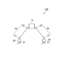
- FIG. 1 is a schematic diagram showing the structure of the robot according to the first embodiment.
- FIG. 2 is a configuration diagram of the back surface of the tip portion.
- FIG. 3 is a back view of the tip portion according to the modified example.
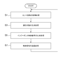
- FIG. 4 is a flowchart relating to the basic flow of impedance control.
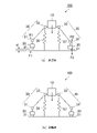
- FIG. 5 is an explanatory diagram of an example in which the target posture is slightly deviated from the ideal posture in the leg portion where the first joint portion is outside the second joint portion.
- FIG. 6 is an explanatory diagram of an example in which the target posture is slightly deviated from the ideal posture in the leg portion in which the first joint portion is inside the second joint portion.
- FIG. 7 is a flowchart relating to rigidity adjustment.
- FIG. 8 is a conceptual diagram regarding the adjustment of rigidity.
- FIG. 9 is an explanatory diagram relating to control in which various methods are combined.
- FIG. 10 is a schematic view of a robot having wheels at the tips of its legs when viewed from
- FIG. 1 is a schematic diagram showing the structure of the robot 100 according to the first embodiment.
- the robot 100 includes a main body portion 10, and the main body portion 10 is connected to and supported by a pair of left and right leg portions 30.
- the shape of the main body 10 is an example for explanation, and may be, for example, a torso extending from the upper body to the upper body of the humanoid robot. Further, various other devices and mechanisms may be mounted or coupled to the main body 10, and for example, a mechanism such as a robot arm or a sensor such as a camera may be provided.
- a mechanism such as a robot arm or a sensor such as a camera may be provided.
- the robot 100 is a humanoid
- the two-armed robot arms provided on the torso and the left and right sides of the torso, the head connected to the upper end of the torso, the camera provided on the head, and the like are included. It may be installed.
- the leg portion 30 has a tip portion 20 that supports the wheel 21 that is in contact with the floor surface, a first joint portion 31 and a second joint portion 33 in order from the tip portion 20, and a link that connects them. It is composed of members.
- the tip portion 20 and the wheel 21 may be collectively referred to as a moving carriage portion or the like.
- a servomotor and a drive shaft which is a shaft for decelerating the output of the servomotor, are arranged in the first joint portion 31 and the second joint portion 33 in order to control the rotation of the joint portions. ing. As will be described later, by controlling this drive shaft, it is possible to control the posture and the like.
- the drive shaft may be the output shaft of the servomotor without deceleration.
- first joint portion 31 and the second joint portion 33 are provided with an angle detection sensor for detecting the joint angle and a torque detection sensor for detecting the torque applied to the joint angle. The control described later is performed based on the detected values from these sensors.
- the leg portion 30 may be configured to enable both bipedal walking and traveling by the wheels 21. According to such a configuration, the robot 100 having high mobility can be realized.
- FIG. 1 although one wheel 21 is provided for each tip portion 20, this is a schematic representation and is actually a floor surface of the tip portion 20. Four wheels 21 are in contact with the side surface (back surface).
- FIG. 2 is a configuration diagram of the back surface of the tip portion 20.
- the tip portion 20 has a rectangular cross section, and four wheels 21a to 21d (driving wheels) driven by a servomotor or the like are provided at the four corners thereof. Further, a plurality of passive wheels 22 having a substantially barrel shape are provided on the ground contact surface of each wheel.
- the wheel 21 which is a so-called Mecanum wheel is exemplified as the moving mechanism traveling on the floor surface, but the moving mechanism is not limited to such a moving mechanism. Therefore, for example, another moving mechanism that can move in all directions, such as an omni wheel, may be adopted. Further, the moving mechanism may be a mechanism that can move in all directions by interlocking a plurality of moving mechanisms even if the moving mechanism cannot move in all directions by itself.
- FIG. 3 is a back view of the tip portion 70 according to a modified example of the movement mechanism that enables movement in all directions for the first time when a plurality of movement mechanisms are interlocked.
- two drive wheels 71a and 71b are arranged at the top and bottom of the figure on the back surface of the tip portion 70.
- a large number of passive wheels 72 having a substantially barrel shape are arranged on the ground contact surface of each of the drive wheels 71a and 71b.
- the controller that controls the operation of the robot 100 is stored in the main body 10.
- the arrangement of the controller is not limited to such an example, and may be arranged at another part of the robot 100 or outside the robot 100. Further, the controller may be further connected to an information processing device arranged inside or outside the robot 100 by wire or wirelessly.
- FIG. 4 is a flowchart relating to the basic flow of impedance control performed in the controller provided in the robot 100. As is clear from the figure, when the impedance control process is started, the process of acquiring the sensor detection value from the angle detection sensor and the torque detection sensor is performed (S1).
- a process of generating the current state that is, the current position and the current posture of the joint portion or the robot 100 is performed based on the sensor signal (S3).
- a predetermined target state that is, a target position and a target posture is read, and an impedance control signal is generated based on the target state and the current state (S5). More specifically, the control signal for impedance control is generated based on the following equation for the spring mass damper model.
- X d represents the target state and X represents the current state.
- ⁇ represents a force to be generated by control
- M represents inertia
- D represents a damping coefficient (viscosity)
- K represents a spring constant (rigidity).
- the present embodiment has been described as performing impedance control in a narrow sense with a position as an input and a force as an output
- the present invention includes impedance control in a broad sense and is limited to such a configuration. Not done. Therefore, for example, admittance control in which a force is input and a position is output may be executed.
- the above calculation may be based on the joint coordinate system or the like, or may be based on another coordinate system fixed to the robot 100.
- the coordinate system fixed to the robot 100 may be, for example, a coordinate system centered on the zero moment point of the robot 100.
- FIG. 5 (b) shows the actual posture resulting from the control shown in FIG. 5 (a).
- the posture is such that the wheels 21 are arranged perpendicularly to the floor surface or a posture close to the posture.
- the target posture is pre-biased in each of the joint portions 31 and 33 urged to the target posture by impedance control
- the tension generated by the virtual springs 51 and 52 causes the ground contact surface.
- the moment and the moment generated on the ground contact surface due to the weight of the main body 10 and the like cancel each other out, and as a result, the ground contact posture can be guided to the ideal posture. That is, it is possible to appropriately secure the traction between the wheel 21 and the floor surface and realize stable movement of the robot 100.
- FIG. 6 is an explanatory diagram of an example in which the target posture is slightly deviated from the ideal posture in the leg portion 30 in which the first joint portion 31 is inside the second joint portion 33.
- the ideal posture is a posture in which the wheels 21 are arranged perpendicular to the floor surface from the viewpoint of ensuring appropriate traction with the wheels 21.
- FIG. 6 (b) shows the actual posture resulting from the control shown in FIG. 6 (a).
- the posture is such that the wheels 21 are arranged perpendicularly to the floor surface or a posture close to the posture.
- the target posture is pre-biased in each of the joints 31 and 33 urged to the target posture by impedance control, the moment generated on the ground contact surface due to the tension generated by the virtual spring and the main body.
- the moments generated on the ground contact surface due to the weight of the portion 10 and the like cancel each other out, and as a result, the ground contact posture can be guided to the ideal posture. That is, it is possible to appropriately secure the traction between the wheel 21 and the floor surface and realize stable movement of the robot 100.
- the ideal posture is the posture in which the relationship between the floor surface and the wheel 21 is vertical, but the ideal posture may be set in other parts.
- the torque applied to each joint is detected based on the detection value of the torque detection sensor provided in each joint portion 31, 33. Based on the torque from each joint, the reaction force actually generated on the ground contact surface of each leg portion 30, that is, the actual reaction force (R1, R2) is calculated (S84).
- the difference (F1-R1, F2-R2) between the calculated ideal reaction force and the actual reaction force is calculated (S85).
- S87YES positive
- S87NO negative
- S87NO negative
- impedance control is performed based on the changed parameters. In any case, after the change processing is completed, the processing returns to the beginning and a series of processing is repeated.
- FIG. 8 is a conceptual diagram relating to the adjustment of rigidity according to this example.
- FIG. 8B is a diagram showing a state after adjusting the rigidity. As is clear from the figure, it can be seen that the floating leg portion 30 is immediately in contact with the ground by reducing the rigidity of the virtual spring 57 on the right side.
- the wheels 21 imitate the ground contact surface in the robot 100 that moves with the plurality of legs 30 and the wheels 21.
- Such an operation can be realized. This makes it possible to prevent the generation of internal stress due to excessive restraint, for example. Further, it is possible to secure traction between the wheel 21 and the ground contact surface. That is, stable movement can be realized in the robot 100 that moves by providing a moving mechanism such as wheels 21 at the tips of the plurality of legs 30.
- FIG. 9 is an explanatory diagram relating to the control of the robot 200 according to this example.
- the robot 200 has substantially the same configuration as the robot 100 shown in FIG. 1, but the leg 130 corresponds to the six joints 131 to 136 of the first to sixth joints. It differs in that it has a 6-axis drive shaft.
- impedance control is executed on the premise of a reference coordinate system centered on a zero moment point (intersection of the Z axis and the Y axis in the center of the figure) arranged in the vicinity of the main body 110 of the robot 200.
- the target posture is biased by tilting the wheel 21 slightly outward with respect to the floor surface (so-called negative camber).
- the joint portions 131 to 136 are impedance-controlled, and more specifically, the joint portions 131 to 136 are urged to return to the target posture as in the virtual spring 151 shown in the figure.
- the spring constant (K) of the virtual spring 151 is set to an appropriate value to the extent necessary to return to the target posture.
- the moment generated on the ground plane due to the spring tension generated by the virtual spring 151 is set to a value slightly smaller than the moment generated on the ground plane due to the weight of the main body 10 or the like.
- the left and right virtual springs 152 that try to hold the zero moment point at a predetermined position or height with respect to the floor surface are set by impedance control.
- the ideal reaction force and the actual reaction force between the wheel 121 and the floor surface are calculated by the above method, and the rigidity parameter of the virtual spring 152 is changed based on the difference.
- the wheel 121 since the drive shaft included in each joint portion 131 to 136 is impedance-controlled, the wheel 121 follows the ground plane in a robot that moves with a plurality of movement mechanism portions. Operation can be realized. This makes it possible to prevent the generation of internal stress due to excessive restraint, for example. Further, it is possible to secure traction between the wheel 121 and the ground contact surface. That is, stable movement can be realized in a robot that moves by providing a movement mechanism unit at the tips of a plurality of legs.
- the present invention can be used at least in the industry of manufacturing mobile robots.
Landscapes
- Engineering & Computer Science (AREA)
- Mechanical Engineering (AREA)
- Chemical & Material Sciences (AREA)
- Combustion & Propulsion (AREA)
- Transportation (AREA)
- Robotics (AREA)
- Manipulator (AREA)
Applications Claiming Priority (2)
| Application Number | Priority Date | Filing Date | Title |
|---|---|---|---|
| JP2020-212774 | 2020-12-22 | ||
| JP2020212774A JP7549340B2 (ja) | 2020-12-22 | 2020-12-22 | ロボット |
Publications (1)
| Publication Number | Publication Date |
|---|---|
| WO2022137746A1 true WO2022137746A1 (ja) | 2022-06-30 |
Family
ID=82158920
Family Applications (1)
| Application Number | Title | Priority Date | Filing Date |
|---|---|---|---|
| PCT/JP2021/037870 Ceased WO2022137746A1 (ja) | 2020-12-22 | 2021-10-13 | ロボット |
Country Status (2)
| Country | Link |
|---|---|
| JP (1) | JP7549340B2 (https=) |
| WO (1) | WO2022137746A1 (https=) |
Cited By (3)
| Publication number | Priority date | Publication date | Assignee | Title |
|---|---|---|---|---|
| CN116142345A (zh) * | 2023-03-20 | 2023-05-23 | 中国铁路设计集团有限公司 | 多向高适应性复合关节支撑腿、高空作业机器人及应用 |
| CN117104363A (zh) * | 2023-08-04 | 2023-11-24 | 北京科技大学 | 一种张拉整体式驱动机器人 |
| WO2026024572A1 (en) * | 2024-07-26 | 2026-01-29 | Mampetta Anish | Legged robot with joint-augmented stability control |
Families Citing this family (4)
| Publication number | Priority date | Publication date | Assignee | Title |
|---|---|---|---|---|
| CN114161402B (zh) * | 2021-12-17 | 2023-11-10 | 深圳市优必选科技股份有限公司 | 机器人稳定控制方法、模型构建方法、装置和机器人 |
| JP2024000312A (ja) | 2022-06-20 | 2024-01-05 | Toppanホールディングス株式会社 | 蛍光物質及び消光物質で標識された一本鎖オリゴヌクレオチド |
| JP7845227B2 (ja) * | 2023-02-28 | 2026-04-14 | 株式会社豊田中央研究所 | 運搬台車 |
| JP2025017182A (ja) * | 2023-07-24 | 2025-02-05 | トヨタ自動車株式会社 | ロボット駆動装置、ロボット駆動方法及びロボット駆動プログラム |
Citations (2)
| Publication number | Priority date | Publication date | Assignee | Title |
|---|---|---|---|---|
| JP2009154256A (ja) * | 2007-12-27 | 2009-07-16 | Yaskawa Electric Corp | 車輪付脚式移動装置 |
| WO2020184318A1 (ja) * | 2019-03-14 | 2020-09-17 | ソニー株式会社 | 情報処理装置、移動体及び移動体の状態判別方法 |
Family Cites Families (1)
| Publication number | Priority date | Publication date | Assignee | Title |
|---|---|---|---|---|
| JP2009113135A (ja) * | 2007-11-05 | 2009-05-28 | Hitachi Ltd | 2足型移動機構 |
-
2020
- 2020-12-22 JP JP2020212774A patent/JP7549340B2/ja active Active
-
2021
- 2021-10-13 WO PCT/JP2021/037870 patent/WO2022137746A1/ja not_active Ceased
Patent Citations (2)
| Publication number | Priority date | Publication date | Assignee | Title |
|---|---|---|---|---|
| JP2009154256A (ja) * | 2007-12-27 | 2009-07-16 | Yaskawa Electric Corp | 車輪付脚式移動装置 |
| WO2020184318A1 (ja) * | 2019-03-14 | 2020-09-17 | ソニー株式会社 | 情報処理装置、移動体及び移動体の状態判別方法 |
Cited By (4)
| Publication number | Priority date | Publication date | Assignee | Title |
|---|---|---|---|---|
| CN116142345A (zh) * | 2023-03-20 | 2023-05-23 | 中国铁路设计集团有限公司 | 多向高适应性复合关节支撑腿、高空作业机器人及应用 |
| CN117104363A (zh) * | 2023-08-04 | 2023-11-24 | 北京科技大学 | 一种张拉整体式驱动机器人 |
| CN117104363B (zh) * | 2023-08-04 | 2026-02-27 | 北京科技大学 | 一种张拉整体式驱动机器人 |
| WO2026024572A1 (en) * | 2024-07-26 | 2026-01-29 | Mampetta Anish | Legged robot with joint-augmented stability control |
Also Published As
| Publication number | Publication date |
|---|---|
| JP2022099034A (ja) | 2022-07-04 |
| JP7549340B2 (ja) | 2024-09-11 |
Similar Documents
| Publication | Publication Date | Title |
|---|---|---|
| WO2022137746A1 (ja) | ロボット | |
| US11738456B2 (en) | Palletizing boxes | |
| US20200306998A1 (en) | Multi-Body Controller | |
| CN106547206B (zh) | 一种基于脚力估计算法的多足机器人动态稳定性定量判定方法 | |
| JP5322562B2 (ja) | 移動台車 | |
| JP7003097B2 (ja) | 無人搬送車 | |
| US20150306765A1 (en) | Control device and control method for robot and the robot | |
| JP2014161991A (ja) | ロボットの移動機構及びそれを備えるロボット | |
| US12422849B2 (en) | Method for building controller for robot, method, device for controlling motion of robot, and robot | |
| US12045044B2 (en) | Transport robot, transport system, and transport method | |
| JP2013094935A (ja) | ロボットアーム装置 | |
| JP2017013214A (ja) | 複数ロボットによる荷物積込み・積降ろしシステム及び方法 | |
| JP4982413B2 (ja) | 脚車輪型移動ロボット | |
| Xu et al. | Obstacle-negotiation performance on challenging terrain for a parallel leg-wheeled robot | |
| Choi et al. | Active suspension for a rapid mobile robot using cartesian computed torque control | |
| CN115194768B (zh) | 一种移动双臂机器人柔顺控制方法 | |
| CN111559217A (zh) | 一种用于提高平衡重式叉车转向稳定性的控制方法 | |
| JP4613539B2 (ja) | ロボットの動作計画方法 | |
| US20250278097A1 (en) | Autonomous Robot Double Drive Assembly | |
| CN108238126A (zh) | 一种轮足全向运动机器人 | |
| KR20120048410A (ko) | 피치 밸런싱 다리형 로봇 | |
| US12005583B2 (en) | Robotic system for moving a payload with minimal payload sway and increased positioning accuracy | |
| WO2023165192A1 (zh) | 机器人控制方法、装置、机器人以及计算机可读存储介质 | |
| KR102866923B1 (ko) | 적재물의 무게에 따른 메인 구동부의 서스펜션 조절기능을 갖춘 운송용 이동 로봇 | |
| CN115697640A (zh) | 移动体以及移动体控制方法 |
Legal Events
| Date | Code | Title | Description |
|---|---|---|---|
| 121 | Ep: the epo has been informed by wipo that ep was designated in this application |
Ref document number: 21909904 Country of ref document: EP Kind code of ref document: A1 |
|
| NENP | Non-entry into the national phase |
Ref country code: DE |
|
| 122 | Ep: pct application non-entry in european phase |
Ref document number: 21909904 Country of ref document: EP Kind code of ref document: A1 |