WO2022137720A1 - 在席情報管理システムおよび在席情報管理方法 - Google Patents
在席情報管理システムおよび在席情報管理方法 Download PDFInfo
- Publication number
- WO2022137720A1 WO2022137720A1 PCT/JP2021/036824 JP2021036824W WO2022137720A1 WO 2022137720 A1 WO2022137720 A1 WO 2022137720A1 JP 2021036824 W JP2021036824 W JP 2021036824W WO 2022137720 A1 WO2022137720 A1 WO 2022137720A1
- Authority
- WO
- WIPO (PCT)
- Prior art keywords
- person
- information
- area
- face
- camera
- Prior art date
- Legal status (The legal status is an assumption and is not a legal conclusion. Google has not performed a legal analysis and makes no representation as to the accuracy of the status listed.)
- Ceased
Links
Images


Classifications
-
- G—PHYSICS
- G06—COMPUTING OR CALCULATING; COUNTING
- G06Q—INFORMATION AND COMMUNICATION TECHNOLOGY [ICT] SPECIALLY ADAPTED FOR ADMINISTRATIVE, COMMERCIAL, FINANCIAL, MANAGERIAL OR SUPERVISORY PURPOSES; SYSTEMS OR METHODS SPECIALLY ADAPTED FOR ADMINISTRATIVE, COMMERCIAL, FINANCIAL, MANAGERIAL OR SUPERVISORY PURPOSES, NOT OTHERWISE PROVIDED FOR
- G06Q10/00—Administration; Management
- G06Q10/10—Office automation; Time management
-
- A—HUMAN NECESSITIES
- A61—MEDICAL OR VETERINARY SCIENCE; HYGIENE
- A61B—DIAGNOSIS; SURGERY; IDENTIFICATION
- A61B5/00—Measuring for diagnostic purposes; Identification of persons
- A61B5/0059—Measuring for diagnostic purposes; Identification of persons using light, e.g. diagnosis by transillumination, diascopy, fluorescence
- A61B5/0077—Devices for viewing the surface of the body, e.g. camera, magnifying lens
-
- A—HUMAN NECESSITIES
- A61—MEDICAL OR VETERINARY SCIENCE; HYGIENE
- A61B—DIAGNOSIS; SURGERY; IDENTIFICATION
- A61B5/00—Measuring for diagnostic purposes; Identification of persons
- A61B5/01—Measuring temperature of body parts ; Diagnostic temperature sensing, e.g. for malignant or inflamed tissue
-
- A—HUMAN NECESSITIES
- A61—MEDICAL OR VETERINARY SCIENCE; HYGIENE
- A61B—DIAGNOSIS; SURGERY; IDENTIFICATION
- A61B5/00—Measuring for diagnostic purposes; Identification of persons
- A61B5/68—Arrangements of detecting, measuring or recording means, e.g. sensors, in relation to patient
- A61B5/6887—Arrangements of detecting, measuring or recording means, e.g. sensors, in relation to patient mounted on external non-worn devices, e.g. non-medical devices
- A61B5/6889—Rooms
-
- G—PHYSICS
- G06—COMPUTING OR CALCULATING; COUNTING
- G06Q—INFORMATION AND COMMUNICATION TECHNOLOGY [ICT] SPECIALLY ADAPTED FOR ADMINISTRATIVE, COMMERCIAL, FINANCIAL, MANAGERIAL OR SUPERVISORY PURPOSES; SYSTEMS OR METHODS SPECIALLY ADAPTED FOR ADMINISTRATIVE, COMMERCIAL, FINANCIAL, MANAGERIAL OR SUPERVISORY PURPOSES, NOT OTHERWISE PROVIDED FOR
- G06Q10/00—Administration; Management
- G06Q10/06—Resources, workflows, human or project management; Enterprise or organisation planning; Enterprise or organisation modelling
-
- G—PHYSICS
- G06—COMPUTING OR CALCULATING; COUNTING
- G06T—IMAGE DATA PROCESSING OR GENERATION, IN GENERAL
- G06T1/00—General purpose image data processing
-
- G—PHYSICS
- G06—COMPUTING OR CALCULATING; COUNTING
- G06T—IMAGE DATA PROCESSING OR GENERATION, IN GENERAL
- G06T7/00—Image analysis
-
- G—PHYSICS
- G06—COMPUTING OR CALCULATING; COUNTING
- G06V—IMAGE OR VIDEO RECOGNITION OR UNDERSTANDING
- G06V20/00—Scenes; Scene-specific elements
- G06V20/50—Context or environment of the image
- G06V20/52—Surveillance or monitoring of activities, e.g. for recognising suspicious objects
-
- G—PHYSICS
- G06—COMPUTING OR CALCULATING; COUNTING
- G06V—IMAGE OR VIDEO RECOGNITION OR UNDERSTANDING
- G06V40/00—Recognition of biometric, human-related or animal-related patterns in image or video data
- G06V40/10—Human or animal bodies, e.g. vehicle occupants or pedestrians; Body parts, e.g. hands
- G06V40/103—Static body considered as a whole, e.g. static pedestrian or occupant recognition
-
- G—PHYSICS
- G06—COMPUTING OR CALCULATING; COUNTING
- G06V—IMAGE OR VIDEO RECOGNITION OR UNDERSTANDING
- G06V40/00—Recognition of biometric, human-related or animal-related patterns in image or video data
- G06V40/10—Human or animal bodies, e.g. vehicle occupants or pedestrians; Body parts, e.g. hands
- G06V40/16—Human faces, e.g. facial parts, sketches or expressions
- G06V40/161—Detection; Localisation; Normalisation
- G06V40/166—Detection; Localisation; Normalisation using acquisition arrangements
-
- G—PHYSICS
- G06—COMPUTING OR CALCULATING; COUNTING
- G06V—IMAGE OR VIDEO RECOGNITION OR UNDERSTANDING
- G06V40/00—Recognition of biometric, human-related or animal-related patterns in image or video data
- G06V40/10—Human or animal bodies, e.g. vehicle occupants or pedestrians; Body parts, e.g. hands
- G06V40/16—Human faces, e.g. facial parts, sketches or expressions
- G06V40/172—Classification, e.g. identification
-
- G—PHYSICS
- G16—INFORMATION AND COMMUNICATION TECHNOLOGY [ICT] SPECIALLY ADAPTED FOR SPECIFIC APPLICATION FIELDS
- G16H—HEALTHCARE INFORMATICS, i.e. INFORMATION AND COMMUNICATION TECHNOLOGY [ICT] SPECIALLY ADAPTED FOR THE HANDLING OR PROCESSING OF MEDICAL OR HEALTHCARE DATA
- G16H40/00—ICT specially adapted for the management or administration of healthcare resources or facilities; ICT specially adapted for the management or operation of medical equipment or devices
- G16H40/60—ICT specially adapted for the management or administration of healthcare resources or facilities; ICT specially adapted for the management or operation of medical equipment or devices for the operation of medical equipment or devices
- G16H40/67—ICT specially adapted for the management or administration of healthcare resources or facilities; ICT specially adapted for the management or operation of medical equipment or devices for the operation of medical equipment or devices for remote operation
-
- A—HUMAN NECESSITIES
- A61—MEDICAL OR VETERINARY SCIENCE; HYGIENE
- A61B—DIAGNOSIS; SURGERY; IDENTIFICATION
- A61B2503/00—Evaluating a particular growth phase or type of persons or animals
- A61B2503/20—Workers
Definitions
- This disclosure relates to an attendance information management system and an attendance information management method in which a processor executes a process of managing the attendance information of a person in the office area.
- a receiver of a wireless tag possessed by the person is installed for each office seat, or the person sits in the office seat.
- a camera that captures the face of the person is installed in each office seat, or a card reader that reads the IC card possessed by the person is installed in each office seat, or the person can use it on the office seat map screen.
- information on the health of the person who entered the office that is, information on health management (for example, whether or not a mask is worn) and health. It is desirable to collect information about the condition (measured body temperature). In this case, if it is possible to collect information on the health of the person in the presence at the same time as collecting the presence information on the presence status of the person, it is possible to efficiently collect the information on the health of the person in the presence. can.
- this disclosure is a facility for identifying a person who is present even if the layout of the office is changed when managing the presence information regarding the presence status of the person in a free address system office.
- the main purpose is to provide an attendance information management system and an attendance information management method that can efficiently collect information on the health of the people present, without having to spend a lot of time updating and adjusting. And.
- the presence information management system of the present disclosure is an presence information management system that executes a process of managing the presence information regarding the presence status of a person in the office area by a processor, and is an in-area camera that photographs the inside of the office area.
- the information gathering robot comprises an information gathering robot traveling in the work area, the information gathering robot has a face camera for photographing the face of a person present in the presence detection area in the work area, and the processor comprises the above.
- the presence of a person in the presence detection area is detected based on the image taken by the camera in the area
- the information collecting robot moves to the vicinity of the presence detection area where the presence is detected and is present.
- the information gathering robot is controlled so as to photograph the face of a person present in the detection area, face matching processing is performed using an image captured by the face camera, and the presence of the person specified by the face matching processing is performed.
- the configuration is such that seat information is generated.
- the attendance information management method of the present disclosure is an attendance information management method in which a processor executes a process of managing the attendance information regarding the attendance status of a person in the office area, and the inside of the office area is photographed.
- a processor executes a process of managing the attendance information regarding the attendance status of a person in the office area, and the inside of the office area is photographed.
- the information collecting robot traveling in the work area moves to the vicinity of the presence detection area where the presence is detected.
- the information collecting robot is controlled so as to take a picture of the face of a person present in the presence detection area, and face matching processing is performed using the image taken by the face camera possessed by the information collecting robot.
- the configuration is such that the presence information regarding the person specified by the face matching process is generated.
- an information gathering robot that freely travels in the office area is arranged as a facility for identifying a person present. Therefore, even if the layout of the office area is changed, it is not necessary to spend a lot of time to update or adjust the equipment.
- Explanatory drawing which shows the attendance status confirmation screen of the map display mode displayed on the user terminal 5 which concerns on 1st Embodiment
- An explanatory diagram showing an attendance status confirmation screen in a department-specific display mode displayed on the user terminal 5 according to the first embodiment.
- a flow chart showing an operation procedure of the attendance management server 3 according to the first embodiment.
- a flow chart showing an operation procedure of the robot control server 4 according to the first embodiment.
- the first invention made to solve the above-mentioned problems is an attendance information management system in which a processor executes a process of managing attendance information regarding the attendance status of a person in the office area, and photographs the inside of the office area.
- the information collecting robot includes a camera in the area to be used and an information collecting robot traveling in the work area, and the information collecting robot has a face camera for photographing the face of a person present in the presence detection area in the work area.
- the processor detects the presence of a person in the presence detection area based on the image taken by the camera in the area, the information collecting robot moves to the vicinity of the presence detection area where the presence is detected.
- the information collecting robot is controlled so as to photograph the face of a person present in the presence detection area, face matching processing using the image taken by the face camera is performed, and the face matching processing is used to identify the robot.
- the configuration is such that the presence information regarding the person is generated.
- an information gathering robot that freely travels in the office area will be placed as a facility for identifying the person present. Therefore, even if the layout of the office area is changed, it is not necessary to spend a lot of time to update or adjust the equipment.
- the second invention is configured such that the processor generates information regarding whether or not a mask is worn for a person present in the presence detection area based on an image taken by the face camera.
- the information collecting robot has a vital sensor, and the processor executes a process of measuring the vital information of a person present in the presence detection area by the vital sensor. It shall be configured.
- vital information can be efficiently collected as information on the health condition of the person present. It is also possible to configure the face camera as a thermo camera that also serves as a vital sensor.
- the processor is configured to measure at least one of body temperature and heart rate as the vital information.
- body temperature and heart rate can be collected as vital information of the person present.
- the processor when the processor detects the presence of a person in the presence detection area, the duration of the absence state before the presence detection area changes to the presence state is a predetermined time. If it is within the range, the presence information is retained, and if the duration of the absence exceeds a predetermined time, the presence information is deleted.
- the sixth invention is configured such that the processor generates an attendance map showing the attendance position of a person in the office area.
- the user can immediately check the presence status of the person in the office area.
- information on the health management and health condition of the person present may be displayed on the attendance map.
- the seventh invention is an attendance information management system that executes a process of managing the attendance information regarding the attendance status of a person in the office area by a processor, and has an entrance camera that captures the vicinity of the entrance of the office area. It is equipped with an in-area camera that shoots the inside of the work area and an information gathering robot that travels in the work area. Having a camera, the processor identifies a person who has entered the office area by performing a person identification process on the person who enters the office area, and detects the presence of the person based on an image taken by the camera in the area.
- a person matching process is performed using the image taken by the entrance camera and the image taken by the camera in the area, and the presence information regarding the person specified by the person matching process is obtained.
- the information gathering robot moves to the vicinity of the presence detection area where the presence is detected, and the face of the person present in the presence detection area.
- the information gathering robot is controlled so as to capture the image, the face matching process using the image taken by the face camera is performed, and the presence information regarding the person specified by the face matching process is generated.
- an information gathering robot that freely travels in the office area will be placed as a facility for identifying the person present. Therefore, even if the layout of the office area is changed, it is not necessary to spend a lot of time to update or adjust the equipment. Further, only when the person matching process fails, the information collecting robot is dispatched to perform the face matching process using the image taken by the face camera of the information collecting robot, so that the frequency of dispatching the information collecting robot can be reduced. ..
- the eighth invention is a presence information management method in which a processor executes a process of managing the presence information regarding the presence status of a person in the work area, and is an image taken by an in-area camera that captures the inside of the work area.
- a processor executes a process of managing the presence information regarding the presence status of a person in the work area, and is an image taken by an in-area camera that captures the inside of the work area.
- the information gathering robot traveling in the work area moves to the vicinity of the presence detection area where the presence is detected, and the information gathering robot moves to the vicinity of the presence detection area.
- the information collecting robot is controlled so as to photograph the face of a person present in the presence detection area, face matching processing is performed using an image taken by a face camera possessed by the information collecting robot, and the face matching processing is performed.
- the configuration is such that the presence information regarding the specified person is generated.
- an information gathering robot that freely travels in the office area is arranged as a facility for identifying a person present. Therefore, even if the layout of the office area is changed, it is not necessary to spend a lot of time to update or adjust the equipment.
- the ninth invention is an attendance information management method for executing a process of managing the attendance information regarding the attendance status of a person in the office area by a processor, and is a person identification process for a person who enters the office area.
- a person collation process is performed using an image taken by the entrance camera that photographs the area around the entrance and an image taken by the camera in the area, and the presence information regarding the person specified by the person collation process is generated to generate the person collation.
- the information gathering robot traveling in the office area moves to the vicinity of the presence detection area where the presence is detected, and the face of the person present in the presence detection area is displayed.
- the information collecting robot is controlled so as to take a picture, face matching processing is performed using the image taken by the face camera possessed by the information collecting robot, and the presence information regarding the person specified by the face matching processing is generated. It shall be configured.
- an information gathering robot that freely travels in the office area is arranged as a facility for identifying a person present. Therefore, even if the layout of the office area is changed, it is not necessary to spend a lot of time to update or adjust the equipment. Further, only when the person matching process fails, the information collecting robot is dispatched to perform the face matching process using the image taken by the face camera of the information collecting robot, so that the frequency of dispatching the information collecting robot can be reduced. ..
- FIG. 1 is an overall configuration diagram of an attendance information management system according to the first embodiment.
- This presence information management system manages the presence information regarding the presence status of a person in a free address system office (office area), and includes an indoor camera 1 (camera in the area) for presence detection and an indoor camera 1 (camera in the area). It includes an information collecting robot 2, an attendance management server 3, a robot control server 4, and a user terminal 5 (user device).
- the indoor camera 1, the attendance management server 3, and the user terminal 5 are connected to the first network.
- the information collecting robot 2, the attendance management server 3, and the robot control server 4 are connected to the second network.
- the information collecting robot 2 performs wireless communication. It should be noted that each device may be connected by a single network.
- the indoor camera 1 is installed in the office room and photographs a person staying in the office room.
- the information collection robot 2 is capable of autonomous traveling, and moves to the vicinity of a person present in the office seat in the office room in response to an instruction from the robot control server 4 to collect information about that person.
- the attendance management server 3 performs a process of managing a person present in the office seat in the office room based on the image taken by the indoor camera 1 and the information collected by the information collecting robot 2. Further, the attendance management server 3 has a function of a distribution server, and distributes the attendance information regarding the attendance status of a person in the office to the user terminal 5 based on the management information registered in the database.
- the robot control server 4 controls the operation of the information collecting robot 2.
- the user terminal 5 presents the presence information regarding the presence status of the person in the office to the user based on the distribution information from the presence management server 3.
- the function of managing the database in the attendance management server 3 and the function of distributing the attendance information may be separated from the attendance management server 3 and each function may be realized by an independent database server and distribution server. good.
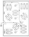
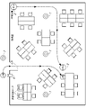
- FIG. 2 is an explanatory diagram showing the layout of the office, the installation status of the indoor camera 1, and the setting status of the presence detection area.
- An indoor camera 1 is installed on the ceiling of the office to take pictures of people staying in the office.
- an omnidirectional camera that shoots a range of 360 degrees using a fisheye lens is adopted.
- a box camera that captures a range of a predetermined angle of view may be adopted as the indoor camera 1.
- a simple camera for example, a USB camera connected to a PC in the office may be adopted as the indoor camera 1.
- an attendance detection area for each office seat is set in advance on the image taken by the indoor camera 1, and it is detected whether or not a person is sitting in the office seat based on the image of this detection area.
- the presence detection area (dotted line area) is represented by a rectangle on the plan view of the office, but in reality, the omnidirectional image (fish eye) taken by the indoor camera 1 is used.
- the presence detection area is set as a polygon on the image).
- This presence detection area is set at a position where the body of the person sitting in the office seat is assumed to exist, and the size of the person's body is set so that one presence detection area corresponds to one person. It is set based on the value. Further, the seating detection area may be set by performing an operation in which the user specifies the range of the seating detection area on the screen displaying the captured image of the indoor camera 1, but the captured image of the indoor camera 1 may be set. Objects (chairs and desks) may be detected from the object, and the presence detection area may be set based on the detection result.
- an information gathering robot 2 is placed in the office.
- the information collecting robot 2 stands by at a predetermined standby position in the office, moves to the vicinity of a person in the office in the office according to an instruction from the robot control server 4, and obtains information about the person. collect.
- the server 3 moves to the vicinity of the target person in order to collect information about the target person.
- the robot control server 4 controls the robot 2 to the vicinity of the target person in order to collect information about the target person.
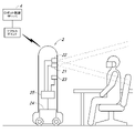
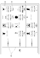
- FIG. 3 is an explanatory diagram showing a schematic configuration of the information collecting robot 2.
- the information collecting robot 2 includes a face camera 21, a vital sensor 22, a speaker 23, a traveling unit 24, and a controller 25.
- the face camera 21 captures the face of the target person present in the office seat.
- a face image for face matching can be obtained from the captured image of the face camera 21.
- the face camera 21 is arranged at a height facing the face of the person sitting in the office seat, and can photograph the face of the person sitting in the office seat at a short distance from the front. Therefore, it is possible to acquire a face image suitable for face matching.
- the vital sensor 22 measures the vital information of the target person present in the office seat, specifically, the body temperature, the heart rate (pulse), etc. in a non-contact manner.
- the vital sensor 22 is, for example, a thermo camera (infrared camera).
- a thermo camera capable of outputting a temperature image and a color image may be adopted for the face camera 21, and the face camera 21 may also serve as the vital sensor 22.
- the speaker 23 outputs various requests, guidance, notifications, and other voices under the control of the robot control server 4. For example, a voice prompting the person to turn his / her face toward the information collecting robot 2 is output from the speaker 23 so that the face of the person can be photographed from the front. In addition, a voice is output from the speaker 23 to guide the forehead not to be hidden by the hair or the like so that the body temperature is appropriately measured. In addition, a voice notifying the name of a person as a face matching result and a measurement result of vital information (for example, a measured value of body temperature) is output from the speaker 23. Further, in the case of a person who does not wear a mask, a voice prompting to wear the mask is output from the speaker 23.
- a voice prompting for hand disinfection is output from the speaker 23.
- a voice notifying that there is fever and prompting to return home is output from the speaker 23.
- the traveling unit 24 includes wheels, a motor, and the like.
- the traveling unit 24 is controlled by the controller 25 so that the information collecting robot 2 autonomously travels.
- the controller 25 includes a communication unit for communicating with the robot control server 4, a storage unit for storing a control program, and a processor for executing the control program.
- the processor performs, for example, travel control processing, and determines a course for avoiding obstacles based on a captured image of the face camera 21 and a detection result of a distance sensor (not shown).
- FIG. 4 is an explanatory diagram showing an outline of processing performed by the attendance management server 3 and the robot control server 4.
- the attendance management server 3 cuts out an image area of the attendance detection area (working seat) from the image taken by the indoor camera 1, acquires an attendance detection area image, and converts the attendance detection area image into an attendance detection area. It is determined whether or not a person exists, and the state of the attendance detection area is set to either present or vacant (absent) according to the determination result (attendance detection processing). This presence detection process is carried out regularly.
- the presence management server 3 is a robot control server so that when the presence of a person in the presence detection area is detected, the information collection robot 2 collects information about the person present in the presence detection area. Instruct 4.
- the robot control server 4 controls the operation of the information collecting robot 2 in response to an instruction for collecting information from the attendance management server 3. Specifically, the information collecting robot 2 is controlled so as to move to the vicinity of the target presence detection area. Further, the information collecting robot 2 is controlled so that the face of the person sitting in the target presence detection area is photographed by the face camera 21.
- the robot control server 4 cuts out an image area of a person's face from the image taken by the face camera 21 to acquire a face image, and extracts face feature information of a person present from the face image. Then, the face feature information of each registered person is compared with the face feature information of the present person to identify the present person (face matching process). By this face matching process, the person present and the registered person are associated with each other, and the person present is specified.
- the robot control server 4 determines whether or not the present person is wearing a mask based on the face image of the present person. Further, the robot control server 4 controls the information collecting robot 2 so as to measure the vital information of the target person with the vital sensor 22, and acquires the measurement result of the vital information.
- the face matching result acquired by the robot control server 4, the determination result of wearing a mask, and the measurement result of vital information are transmitted to the attendance management server 3 and registered in the attendance database.
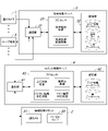
- FIG. 5 is a block diagram showing a schematic configuration of the attendance management server 3 and the robot control server 4.
- the attendance management server 3 includes a communication unit 31, a storage unit 32, and a processor 33.
- the communication unit 31 communicates with the robot control server 4, sends a dispatch instruction of the information collecting robot 2 to the robot control server 4, and outputs a face matching result, a measurement result of vital information, and a determination result of wearing a mask to the robot control server 4. Receive from. Further, the communication unit 31 communicates with the user terminal 5 and transmits the presence information regarding the presence status of the person in the office to the user terminal 5. Further, the communication unit 31 communicates with the indoor camera 1 and receives a captured image from the indoor camera 1.
- the storage unit 32 stores a program or the like executed by the processor 33. Further, the storage unit 32 stores the registration information of the area management database, the attendance database, and the person database. In the area management database, management information of the presence detection area, specifically, the area ID and location information of the presence detection area are registered. Information such as an area ID, an attendance detection time, a person collation result information, specifically, a person ID, and a person collation score is registered in the attendance database. Information such as person management information, specifically, person ID, person's name, affiliation, and job title is registered in the person database. Further, the storage unit 32 temporarily stores the captured image of the indoor camera 1.
- the processor 33 performs various processes by executing the program stored in the storage unit 32.
- the processor 33 performs attendance detection processing, attendance information distribution processing, and the like.
- the processor 33 detects a person in the image area of the presence detection area in the captured image of the indoor camera 1 and determines whether or not a person exists in the target presence detection area. do.
- the state of the presence detection area is set to be present.
- the state of the presence detection area is set to vacant (absent). Then, the attendance detection result information (attendance detection time, the number of areas) and the attendance detection result detailed information (attendance detection time, area ID, detection state) are stored in the storage unit 32.
- the processor 33 In the presence information distribution process, the processor 33 generates information (such as the presence position) regarding the presence status of the person in the office room based on the information registered in each of the presence database and the person database. The information is distributed to the user terminal 5. In the present embodiment, the display information of the attendance status confirmation screen (see FIGS. 6 and 7) is distributed to the user terminal 5.
- the robot control server 4 includes a communication unit 41, a storage unit 42, and a processor 43.
- the communication unit 41 communicates with the information collection robot 2, transmits control information to the information collection robot 2, and receives the captured image of the face camera 21 and the detection result of the vital sensor 22 from the information collection robot 2. Further, the communication unit 41 communicates with the attendance management server 3 and transmits the face matching result acquired by the processor 43, the measurement result of vital information, and the determination result of wearing a mask to the attendance management server 3.
- the storage unit 42 stores a program or the like executed by the processor 43. Further, the storage unit 42 stores the registration information of the area management database and the face database.
- the area management database management information of the presence detection area, specifically, the area ID and location information of the presence detection area are registered.
- the face database information such as face matching information for each person registered in advance, specifically, a person ID and face feature information is registered.
- the processor 43 performs various processes by executing the program stored in the storage unit 42.
- the processor 43 performs travel control processing, face matching processing, vital information measurement processing, mask wearing determination processing, and the like.
- the processor 43 sets a target position in the vicinity of the target presence detection area, that is, the presence detection area where the presence of a person is detected, and moves from the standby position to the target position. Controls the information gathering robot 2. Further, in the travel control process, the processor 43 controls the information collecting robot 2 so as to return to the standby position.
- a plurality of target positions are set by a plurality of people sitting in succession, they do not move to the target positions in the order in which the presence is detected, but are close to the current position of the information gathering robot 2, for example.
- the route optimization for setting the optimum route (shortest route) capable of sequentially moving to the target position in order may be appropriately executed every time the presence detection result is updated.
- the processor 43 determines whether or not the target person is wearing a mask based on the captured image of the face camera 21 of the information collecting robot 2.
- the processor 43 controls the information collecting robot 2 so that the face of a person present in the target presence detection area is photographed by the face camera 21.
- the facial feature information of the target person is extracted from the captured image of the face camera 21 received from the information collecting robot 2.
- the face feature information of each registered person is acquired from the storage unit 42, the face feature information of each registered person is collated with the face feature information of the target person, and the target presence is present. Identify the person present in the seat detection area.
- the matching is performed by excluding the mask area in the face image.
- the processor 43 controls the information collecting robot 2 so that the vital information (body temperature, heart rate, etc.) of the target person is measured by the vital sensor 22, and the vital received from the information collecting robot 2. Based on the detection result of the sensor 22, the measurement result of the vital information is acquired.
- the position of the forehead or the like in the temperature image by the thermo camera as the vital sensor 22 is specified based on the detection result of the face in the image (color image) taken by the face camera 21. And get the temperature of the area such as its forehead.
- the body temperature may be measured by measuring the temperature value indicating the highest temperature among the epidermis temperatures of the face as the body temperature without specifying the position of the forehead or the like.
- the facial expression of the person may be determined based on the image taken by the face camera 21, and the information on the physical condition of the person estimated from the facial expression of the person may be acquired as the measurement result of the vital information. .. Further, as a measurement result of vital information, the degree of tension of the person estimated from the heart rate may be acquired.
- FIG. 6 is an explanatory diagram showing an attendance status confirmation screen in the map display mode displayed on the user terminal 5.
- FIG. 7 is an explanatory diagram showing an attendance status confirmation screen of the department-specific display mode displayed on the user terminal 5.
- the attendance management server 3 generates an attendance status confirmation screen that presents the attendance status of a person in the office based on the information registered in the database, and distributes the display information to the user terminal 5, and the user.
- the attendance status confirmation screen in the map display mode shown in FIG. 6 and the attendance status confirmation screen in the department-specific display mode (list display mode) shown in FIG. 7 are displayed.
- the map display mode and the department-specific display mode can be switched by a predetermined screen operation.
- the layout drawing 51 (area map) of the offices in which each office seat is drawn is displayed, and each of the layout drawings 51 in the layout drawing 51 is displayed.
- a person icon 52 (an image showing the seating position of the person) representing a person sitting in the office seat is displayed.
- a face image of a person is displayed on the person icon 52.
- the person icon 52 may display a portrait of the person, characters representing the name of the person, and the like.
- a balloon 53 person information display unit
- Detailed information about the person is displayed in the balloon 53.
- the name of the person the name of the person, the identification information (area number) of the presence detection area (working seat), the measured value of the body temperature, and whether or not the mask is worn
- the mask icon 54 is displayed as information about.
- the shape of the mask icon 54 changes depending on whether or not the mask is worn.
- a department-specific display column 55 is provided, and a person-specific display column 56 is provided in the department-specific display column 55.
- a person's face image, a person's name, identification information (area number) of the presence detection area (office seat), a measured value of body temperature, and a mask icon 54 are displayed. .. In the example shown in FIG. 7, only the face image of the person and the name of the person are displayed for the absent person.
- the corresponding person-specific display column 56 may be highlighted. In the example shown in FIG. 7, the measured value of body temperature is displayed in bold red. If the body temperature falls within the range of fever, or if the mask is not worn, an alert by pop-up screen or voice may be issued.
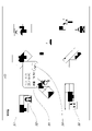
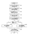
- FIG. 8 is a flow chart showing an operation procedure of the attendance management server 3.
- the processor 33 first performs the attendance detection process (ST101).
- the processor 33 acquires a photographed image of the indoor camera 1, detects a person in the image area of the presence detection area in the photographed image, and sets the target presence detection area. Determine if a person exists. Then, when the processor 33 has a person present in the target presence detection area, the state of the target presence detection area is set as the presence, and when the person does not exist in the target presence detection area. The processor 33 sets the state of the target presence detection area as vacant (absent), and stores the presence detection result in the storage unit 32. Even when a person does not exist in the target presence detection area, if the person's belongings are detected by temporarily leaving the seat, the state of the presence detection area should be treated as being present. You may do it.
- the processor 33 determines whether or not the state of the presence detection area has changed (ST102).
- the processor 33 uses the information collecting robot 2 for all the presence detection areas whose state has changed.
- Information collection processing (information collection loop) is performed (ST103 to ST112).
- the processor 33 determines whether or not the state of the presence detection area has changed from vacant (absent) to present (ST104).
- the processor 33 determines whether or not the check, that is, the instruction for collecting information by the information collecting robot 2 has not been performed yet (ST105).
- the processor 33 collects information about the person present in the target presence detection area by the information collection robot.
- An instruction for collecting information to be performed by 2 is transmitted from the communication unit 31 to the robot control server 4 (ST106).
- the processor 33 acquires the resident person information received from the robot control server 4 by the communication unit 31, that is, the face matching result, the measurement result of the vital information, and the determination result of wearing the mask (ST107).
- the processor 33 updates the registration information about the person in the attendance database (ST108). That is, the person ID as the face matching result for the person associated with the target presence detection area, the measurement result of vital information, and the determination result of wearing the mask are registered in the presence database. Further, the processor 33 updates the registration information regarding the state of the target area in the attendance database to attendance (ST109). Then, the process proceeds to the next presence detection area.
- the processor 33 collects information. It is determined whether or not a predetermined time or more has elapsed since the instruction for collecting information by the robot 2 was given (ST110).
- the processor 33 inputs the registration information regarding the state of the target presence detection area in the presence database to the vacant seat. Update to (ST111). Then, the process proceeds to the next presence detection area.
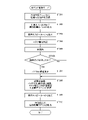
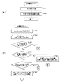
- FIG. 9 is a flow chart showing an operation procedure of the robot control server 4.
- the communication unit 41 receives an instruction for information collection by the information collection robot 2 from the attendance management server 3 (ST201).
- the processor 43 sets a target position in the vicinity of the target presence detection area, that is, the presence detection area where the presence is detected, and the information gathering robot moves from the standby position to the target position. 2 is controlled (ST202).
- the processor 43 controls the information gathering robot 2 so as to output a voice prompting a person to turn his / her face toward the information gathering robot 2 from the speaker 23. ST203). At this time, the processor 43 controls the information collecting robot 2 so that the face camera 21 captures the face of the person sitting in the target presence detection area.
- the processor 43 performs a mask wearing determination process (ST204). At this time, the processor 43 determines whether or not the target person is wearing a mask based on the captured image of the face camera 21 received from the information collecting robot 2.
- the processor 43 performs face matching processing (ST205). At this time, the facial feature information of the target person is extracted from the image taken by the face camera 21. Then, the face feature information of each registered person is acquired from the storage unit 42, the face feature information of each registered person is compared with the face feature information of the target person, and the face matching score is obtained. get.
- the processor 43 determines whether or not the face matching is successful, that is, whether or not the target person matches the registered person based on the face matching score (ST206).
- the processor 43 performs vital information measurement processing (ST207). At this time, the processor 43 controls the information collecting robot 2 so that the vital information of the target person is measured by the vital sensor 22, and acquires the measurement result of the vital information received from the information collecting robot 2.
- the processor 43 transmits the attended person information, that is, the face matching result, the measurement result of the vital information, and the determination result of wearing the mask from the communication unit 41 to the attended management server 3 (ST208).
- the processor 43 tells the target person that the information collection has been completed, the result of the information collection, that is, the name of the person as the face matching result, and the measurement result of the vital information (for example, the measured value of the body temperature).
- the information collecting robot 2 is controlled so as to output the voice notifying the information from the speaker 23 (ST209).
- the processor 43 controls the information collecting robot 2 so as to return to a predetermined standby position (ST210).
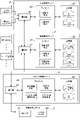
- FIG. 10 is an overall configuration diagram of the attendance information management system according to the second embodiment.
- the attendance information management system includes an indoor camera 1, an attendance management server 3, an information collection robot 2, a robot control server 4, and a user. It is equipped with a terminal 5 (user device), and further includes a first entrance camera 6 for face matching, a second entrance camera 7 for person matching, and an entrance management server 8. ..
- the first entrance camera 6 is installed around the entrance of the office and photographs the face of a person who undergoes face verification (face recognition).
- the second entrance camera 7 is installed around the entrance of the office and photographs a person entering the room from the entrance of the office.
- the room entry management server 8 performs a process of managing a person who enters the office based on the captured image of the first entrance camera 6 and the captured image of the second entrance camera 7.
- the indoor camera 1 is installed in the office room as in the first embodiment, and photographs a person staying in the office room.
- the indoor camera 1 is used not only for seating detection but also for person collation as in the first embodiment.
- the attendance management server 3 manages the person present in the office seat in the office room based on the image taken by the indoor camera 1 and the information collected by the information collecting robot 2. Perform processing.
- FIG. 11 is an explanatory diagram showing the installation status of the first entrance camera 6 and the second entrance camera 7.
- the layout of the office, the installation status of the indoor camera 1, and the setting status of the presence detection area are the same as those in the first embodiment (see FIG. 2).
- a first entrance camera 6 and a second entrance camera 7 are installed at the entrance of the office.
- the first entrance camera 6 a box camera that captures a range of a predetermined angle of view is adopted.
- the first entrance camera 6 captures the face of a person entering the office.
- an omnidirectional camera that captures a range of 360 degrees using a fisheye lens is adopted.
- the second entrance camera 7 photographs the whole body or upper body of a person entering the office.
- the second entrance camera 7 is installed outside the office, but the second entrance camera 7 is installed inside the office and the room is being entered from the entrance. The whole body or upper body of the person may be photographed.
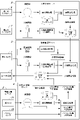
- FIG. 12 is an explanatory diagram showing an outline of processing performed by the room entry management server 8, the attendance management server 3, and the robot control server 4.
- the room entry management server 8 cuts out an image area of a person's face from the image taken by the first entrance camera 6 to acquire a face image, and extracts facial feature information of the person entering the room from the face image. Then, the face feature information of each registered person is compared with the face feature information of the person entering the room to identify the person entering the room (face matching process). By this face matching process, the person who enters the room and the registered person are associated with each other, and the person who enters the room is specified. The person ID of the person who enters the room is registered in the room entry database. In addition, if face verification (face recognition) is successful, a person can enter the office.
- face authentication face verification
- the person identification process may be performed by card authentication, biometrics authentication, or the like.
- the room entry management server 8 cuts out an image area of the whole body or the upper body of the person from the image taken by the second entrance camera 7 at the same time as the face matching, and the person image (first). (People image) is acquired, and the person characteristic information of the person entering the room is extracted from the person image (person detection process). The personal characteristic information of the person entering the room is registered in the room entry database.
- the person characteristic information represents the appearance characteristics of the whole body or upper body of the person, such as the color of the person's clothes, the luggage carried by the person, and the skeleton of the person's body.
- the first entrance camera 6 for face matching and the second entrance camera 7 for person matching are provided, but one camera (for example, an omnidirectional camera) is used for the face.
- the configuration may be used for both collation and person collation.
- the image area of the face may be cut out from the panoramic image obtained by panoramic development of the omnidirectional image and the face image may be acquired.
- the attendance management server 3 cuts out an image area of the attendance detection area (working seat) from the image taken by the indoor camera 1, acquires an attendance detection area image, and acquires the attendance detection area image. From the image, it is determined whether or not a person exists in the attendance detection area, and the state of the attendance detection area is set to either present or vacant according to the determination result (attendance detection processing). ..
- the occupancy management server 3 can see the whole body or upper body of the person from the image taken by the indoor camera 1 immediately before that.
- a person image (second person image) is acquired by cutting out an image area, and person characteristic information about the person immediately before sitting is extracted from the person image.
- the personal characteristic information of the person entering the room registered in the entry database of the room entry management server 8 is collated with the personal characteristic information of the person immediately before sitting (person matching process).
- a person image is acquired from an image taken in a standing state immediately before the person sits in the office seat, and person feature information is extracted from the person image.
- face matching is performed using the captured image of the face camera 21 of the information collecting robot 2 for all the persons whose presence is detected. That is, every time the presence of a person in the presence detection area (working seat) is detected, the information collecting robot 2 is dispatched to perform face matching using the captured image of the face camera 21. Therefore, the frequency of dispatching the information collecting robot 2 may increase at the start of work or the like.
- the image taken by the face camera 21 of the information collecting robot 2 is used for that person.
- the face matching using the face matching is performed, and the face matching using the image taken by the face camera 21 of the information collecting robot 2 is omitted for the person who has succeeded in the person matching. Therefore, the frequency of dispatching the information collecting robot 2 can be reduced.
- the information gathering robot 2 when the person matching using the image taken by the indoor camera 1 fails, the information gathering robot 2 is used for face matching to identify the person present in the presence detection area (working seat). However, even if the person matching using the image taken by the indoor camera 1 is successful, the information gathering robot 2 is dispatched to measure the vital information by the vital sensor 22 and to determine whether the mask is worn. May be.
- FIG. 13 is a block diagram showing a schematic configuration of the room entry management server 8, the attendance management server 3, and the robot control server 4.
- the room entry management server 8 includes a communication unit 81, a storage unit 82, and a processor 83.
- the communication unit 81 communicates with the first entrance camera 6 and the second entrance camera 7, and receives captured images from the first entrance camera 6 and the second entrance camera 7. Further, the communication unit 81 communicates with the attendance management server 3.
- the storage unit 82 stores a program or the like executed by the processor 83. Further, the storage unit 82 stores the registration information of the face database. In the face database, information such as face matching information for each person registered in advance, specifically, a person ID and face feature information is registered. Further, the storage unit 82 stores the registration information of the room entry database. Information such as face matching result information, specifically, face matching time, camera ID, person ID, and face matching score, and personal feature information are registered in the entry database. Further, the storage unit 82 temporarily stores the captured image of the second entrance camera 7.
- the processor 83 performs various processes by executing the program stored in the storage unit 82.
- the processor 83 performs face matching processing, person detection processing, and the like.
- the processor 83 cuts out an image area of the face of a person entering the room from the image taken by the first entrance camera 6 to acquire a face image, and the person entering the room is obtained from the face image. Extract facial feature information. Then, the face feature information of each registered person is acquired from the storage unit 82, the face feature information of each registered person is collated with the face feature information of the person entering the room, and the person entering the room is specified. do.
- the processor 83 detects a person from the image captured by the second entrance camera 7, cuts out an image area of the whole body or upper body of the person from the image captured by the second entrance camera 7, and acquires a person image. Then, the person characteristic information of the person entering the room is extracted from the person image. The person characteristic information of the person entering the room is registered in the room entry database of the room entry management server 8. It is possible to cut out a person image directly from the image (omnidirectional image) taken by the second entrance camera 7 (omnidirectional camera), but after panoramic development, the person image is cut out from the shot image (panorama image). You may.
- the face matching result information acquired by the face matching process and the person characteristic information acquired by the person detection process are registered in the entry database in a state of being linked as the same person.
- the configuration of the attendance management server 3 is the same as that of the first embodiment (see FIG. 5).
- the processor 33 of the attendance management server 3 performs the attendance detection process and the attendance information distribution process as in the first embodiment, but in the present embodiment, the person collation process is further performed.
- the state of the presence detection area acquired by the processor 33 in the presence detection process changes from vacant seat to seated, that is, when a person is seated, the image taken by the indoor camera 1 immediately before that.
- a person image is acquired by cutting out an image area of the whole body or the upper body of the person from the person image, and the person characteristic information about the person immediately before sitting is extracted from the person image.
- a photographed image of the indoor camera 1 at a time when a predetermined number of frames are traced back from the timing when the person is detected to be seated is acquired, and the person is captured from the photographed image. All you have to do is get the image.
- the indoor camera 1 is an omnidirectional camera, it is preferable to acquire a person image from a panoramic image obtained by panoramicly expanding the captured image.
- the person existing in the vicinity of the office seat where the seating is detected is selected from the persons detected from the image taken by the indoor camera 1.
- the person characteristic information about the person may be extracted.
- FIG. 14 is a flow chart showing an operation procedure of the room entry management server 8.
- the processor 83 acquires the captured image received from the first entrance camera 6 by the communication unit 81 (ST301). Next, the processor 83 extracts the facial feature information of the person entering the room from the captured image of the first entrance camera 6 (ST302). Next, the processor 83 acquires the face feature information for each registered person from the storage unit 82, compares the face feature information for each registered person with the face feature information for the person entering the room, and compares the face feature information. Acquire a face matching score (ST303).
- the processor 83 acquires the captured image received from the second entrance camera 7 by the communication unit 81 (ST304). At this time, the captured image of the second entrance camera 7 at the same time as or close to the captured image of the first entrance camera 6 is acquired. Next, the processor 83 extracts the person characteristic information of the person entering the room from the image taken by the second entrance camera 7 (ST305).
- the processor 83 determines whether or not the face matching score is equal to or higher than a predetermined threshold value (face matching score determination) (ST306).
- the processor 83 identifies the person who enters the room and sets the person ID and the face matching score. Generates face matching result information including (ST308).
- the processor 83 generates face collation result information not including the person ID, assuming that there is no corresponding person. (ST307).
- the processor 83 registers the face matching result information and the personal feature information in the entry database (ST309).
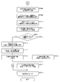
- 15 and 16 are flow charts showing an operation procedure of the attendance management server 3.
- the processor 33 performs the attendance detection process as in the first embodiment (ST401). Then, the processor 33 stores the presence detection result information in the storage unit 32 (ST402).
- the processor 33 acquires the attendance detection result information from the storage unit 32 (ST501). Then, the processor 33 performs an information collection process (information collection loop) for all the presence detection areas where the presence is detected (ST502 to ST518).
- the processor 33 first determines whether or not the state of the presence detection area has changed (ST503).
- the processor 33 determines whether or not the state of the presence detection area has changed from vacant (absent) to present. (ST504).
- the processor 33 is vacant seat before changing to the vacant seat. It is determined whether or not the duration of the state exceeds a predetermined time (for example, 3 hours) (ST506).
- the process proceeds to the next presence detection area.
- the processor 33 acquires the captured image of the indoor camera 1 immediately before the timing when the person is seated from the storage unit 42 (ST508). Then, the person characteristic information about the person immediately before sitting is extracted from the image taken by the indoor camera 1 (ST509).
- the processor 33 acquires the person characteristic information at the time of entering the room registered in the room entry database from the room entry management server 8 (ST510). Then, the processor 33 compares the person characteristic information at the time of entering the room with the person characteristic information immediately before sitting, and acquires the person matching score (ST511).
- the processor 33 determines whether or not the person matching score is equal to or higher than a predetermined threshold value (ST512).
- the processor 33 identifies the person present and the person ID and the person. Generate person collation result information including collation score (ST516).
- the processor 33 collects information about the person present in the target presence detection area.
- the communication unit 31 transmits an instruction for collecting information to be performed by the robot control server 4 to the robot control server 4 (ST513).
- the processor 33 acquires the resident person information received from the robot control server 4 by the communication unit 31, that is, the person ID as the face matching result, the measurement result of the vital information, and the determination result of wearing the mask (ST514). ).
- the processor 33 generates the person collation result information including the person ID (ST515).
- the processor 33 registers the person collation result information in the attendance database (ST517). Then, the process proceeds to the next presence detection area. If the person matching is successful and the information of the corresponding person is registered in the attendance database, the information of the person is deleted from the entry database.
- the processor 33 when the state of the occupancy detection area changes from vacant to vacant (No in ST504), the processor 33 then inputs the registration information regarding the state of the target occupancy detection area in the occupancy database to vacant seats. Update to (ST505). Then, the process proceeds to the next presence detection area.
- the operation procedure of the robot control server 4 is the same as that of the first embodiment (see FIG. 9).
- the occupancy information management system and occupancy information management method according to this disclosure are used in offices with a free address system, even if the layout of the office is changed when acquiring occupancy information regarding the occupancy status of a person. It does not require much effort to update or adjust the equipment to identify the person in the office, and it has the effect of efficiently collecting information on the health of the person in the office, in the office area. It is useful as an attendance information management system and an attendance information management method that execute a process of managing the attendance information regarding the attendance status of a person by a processor.
Landscapes
- Engineering & Computer Science (AREA)
- Health & Medical Sciences (AREA)
- Life Sciences & Earth Sciences (AREA)
- Physics & Mathematics (AREA)
- Theoretical Computer Science (AREA)
- General Physics & Mathematics (AREA)
- General Health & Medical Sciences (AREA)
- Business, Economics & Management (AREA)
- Biomedical Technology (AREA)
- Medical Informatics (AREA)
- Public Health (AREA)
- Multimedia (AREA)
- Surgery (AREA)
- Veterinary Medicine (AREA)
- Molecular Biology (AREA)
- Entrepreneurship & Innovation (AREA)
- Human Resources & Organizations (AREA)
- Strategic Management (AREA)
- Animal Behavior & Ethology (AREA)
- Biophysics (AREA)
- Pathology (AREA)
- Heart & Thoracic Surgery (AREA)
- Human Computer Interaction (AREA)
- General Business, Economics & Management (AREA)
- Economics (AREA)
- Oral & Maxillofacial Surgery (AREA)
- Tourism & Hospitality (AREA)
- Quality & Reliability (AREA)
- Operations Research (AREA)
- Marketing (AREA)
- Data Mining & Analysis (AREA)
- Epidemiology (AREA)
- Primary Health Care (AREA)
- Computer Vision & Pattern Recognition (AREA)
- Development Economics (AREA)
- Educational Administration (AREA)
- Game Theory and Decision Science (AREA)
- Collating Specific Patterns (AREA)
- Management, Administration, Business Operations System, And Electronic Commerce (AREA)
- Image Input (AREA)
Priority Applications (2)
| Application Number | Priority Date | Filing Date | Title |
|---|---|---|---|
| CN202180086533.4A CN116670730A (zh) | 2020-12-21 | 2021-10-05 | 存在信息管理系统和存在信息管理方法 |
| US18/268,479 US20240112139A1 (en) | 2020-12-21 | 2021-10-05 | Presence information management system and presence information management method |
Applications Claiming Priority (2)
| Application Number | Priority Date | Filing Date | Title |
|---|---|---|---|
| JP2020-211007 | 2020-12-21 | ||
| JP2020211007A JP7591727B2 (ja) | 2020-12-21 | 2020-12-21 | 在席情報管理システムおよび在席情報管理方法 |
Publications (1)
| Publication Number | Publication Date |
|---|---|
| WO2022137720A1 true WO2022137720A1 (ja) | 2022-06-30 |
Family
ID=82157519
Family Applications (1)
| Application Number | Title | Priority Date | Filing Date |
|---|---|---|---|
| PCT/JP2021/036824 Ceased WO2022137720A1 (ja) | 2020-12-21 | 2021-10-05 | 在席情報管理システムおよび在席情報管理方法 |
Country Status (4)
| Country | Link |
|---|---|
| US (1) | US20240112139A1 (enExample) |
| JP (1) | JP7591727B2 (enExample) |
| CN (1) | CN116670730A (enExample) |
| WO (1) | WO2022137720A1 (enExample) |
Cited By (1)
| Publication number | Priority date | Publication date | Assignee | Title |
|---|---|---|---|---|
| WO2024185076A1 (ja) * | 2023-03-08 | 2024-09-12 | 三菱電機株式会社 | ロボット装置、制御システム、制御方法、及びプログラム |
Families Citing this family (2)
| Publication number | Priority date | Publication date | Assignee | Title |
|---|---|---|---|---|
| WO2021171614A1 (ja) * | 2020-02-28 | 2021-09-02 | 日本電気株式会社 | サーバ装置、入退場管理システム、入退場管理方法及びプログラム |
| JP7789036B2 (ja) * | 2023-06-29 | 2025-12-19 | 三菱電機ビルソリューションズ株式会社 | 配送ロボットシステムおよびその制御方法 |
Citations (5)
| Publication number | Priority date | Publication date | Assignee | Title |
|---|---|---|---|---|
| JP2007293741A (ja) * | 2006-04-27 | 2007-11-08 | Omron Corp | 監視装置および方法、登録者照合装置、属性推定装置および方法、並びにプログラム |
| JP2008310680A (ja) * | 2007-06-15 | 2008-12-25 | Olympus Corp | 制御システム、プログラム及び情報記憶媒体 |
| JP2018173788A (ja) * | 2017-03-31 | 2018-11-08 | 日本電気株式会社 | 照合システム、管理装置、照合方法、及びプログラム |
| JP2018181223A (ja) * | 2017-04-21 | 2018-11-15 | パナソニックIpマネジメント株式会社 | 滞在状況表示システムおよび滞在状況表示方法 |
| WO2020050413A1 (ja) * | 2018-09-06 | 2020-03-12 | Necソリューションイノベータ株式会社 | 認証用顔画像候補判定装置、認証用顔画像候補判定方法、プログラム、および記録媒体 |
Family Cites Families (10)
| Publication number | Priority date | Publication date | Assignee | Title |
|---|---|---|---|---|
| ATE522330T1 (de) * | 2005-09-30 | 2011-09-15 | Irobot Corp | Robotersystem mit kabelloser kommunikation mittels tcp/ip übertragung |
| US7733224B2 (en) * | 2006-06-30 | 2010-06-08 | Bao Tran | Mesh network personal emergency response appliance |
| JP2012017936A (ja) * | 2010-07-09 | 2012-01-26 | Shimizu Corp | ワークプレイス環境の管理支援システム |
| US11212487B2 (en) * | 2017-04-21 | 2021-12-28 | Panasonic Intellectual Property Management Co., Ltd. | Staying state display system and staying state display method |
| JP7012266B2 (ja) * | 2018-02-22 | 2022-01-28 | パナソニックIpマネジメント株式会社 | 執務席提示システムおよび執務席提示方法 |
| JP7114407B2 (ja) * | 2018-08-30 | 2022-08-08 | 株式会社東芝 | 照合システム |
| US10896321B2 (en) * | 2018-10-19 | 2021-01-19 | Codex Corporation | Monitoring inmate movement with facial recognition |
| US20220331028A1 (en) * | 2019-08-30 | 2022-10-20 | Metralabs Gmbh Neue Technologien Und Systeme | System for Capturing Movement Patterns and/or Vital Signs of a Person |
| EP4104037A1 (en) * | 2020-02-13 | 2022-12-21 | Masimo Corporation | System and method for monitoring clinical activities |
| JP2020140732A (ja) * | 2020-05-29 | 2020-09-03 | パソナ・パナソニックビジネスサービス株式会社 | 認証システム、サーバ、認証プログラム |
-
2020
- 2020-12-21 JP JP2020211007A patent/JP7591727B2/ja active Active
-
2021
- 2021-10-05 WO PCT/JP2021/036824 patent/WO2022137720A1/ja not_active Ceased
- 2021-10-05 US US18/268,479 patent/US20240112139A1/en not_active Abandoned
- 2021-10-05 CN CN202180086533.4A patent/CN116670730A/zh active Pending
Patent Citations (5)
| Publication number | Priority date | Publication date | Assignee | Title |
|---|---|---|---|---|
| JP2007293741A (ja) * | 2006-04-27 | 2007-11-08 | Omron Corp | 監視装置および方法、登録者照合装置、属性推定装置および方法、並びにプログラム |
| JP2008310680A (ja) * | 2007-06-15 | 2008-12-25 | Olympus Corp | 制御システム、プログラム及び情報記憶媒体 |
| JP2018173788A (ja) * | 2017-03-31 | 2018-11-08 | 日本電気株式会社 | 照合システム、管理装置、照合方法、及びプログラム |
| JP2018181223A (ja) * | 2017-04-21 | 2018-11-15 | パナソニックIpマネジメント株式会社 | 滞在状況表示システムおよび滞在状況表示方法 |
| WO2020050413A1 (ja) * | 2018-09-06 | 2020-03-12 | Necソリューションイノベータ株式会社 | 認証用顔画像候補判定装置、認証用顔画像候補判定方法、プログラム、および記録媒体 |
Cited By (2)
| Publication number | Priority date | Publication date | Assignee | Title |
|---|---|---|---|---|
| WO2024185076A1 (ja) * | 2023-03-08 | 2024-09-12 | 三菱電機株式会社 | ロボット装置、制御システム、制御方法、及びプログラム |
| JPWO2024185076A1 (enExample) * | 2023-03-08 | 2024-09-12 |
Also Published As
| Publication number | Publication date |
|---|---|
| CN116670730A (zh) | 2023-08-29 |
| JP7591727B2 (ja) | 2024-11-29 |
| JP2022097829A (ja) | 2022-07-01 |
| US20240112139A1 (en) | 2024-04-04 |
Similar Documents
| Publication | Publication Date | Title |
|---|---|---|
| WO2022137720A1 (ja) | 在席情報管理システムおよび在席情報管理方法 | |
| JP7012266B2 (ja) | 執務席提示システムおよび執務席提示方法 | |
| JP6246403B1 (ja) | 入場管理システム | |
| CN115668269A (zh) | 信息处理装置、信息处理方法和程序 | |
| US10024667B2 (en) | Wearable earpiece for providing social and environmental awareness | |
| US11138420B2 (en) | People stream analysis method, people stream analysis apparatus, and people stream analysis system | |
| JPWO2019181499A1 (ja) | 店舗管理装置および店舗管理方法 | |
| CN113630721B (zh) | 推荐游览路线的生成方法和装置、及计算机可读存储介质 | |
| US20210042859A1 (en) | Facility usage assistance method, facility usage assistance device, and user terminal device | |
| JP2000200357A5 (enExample) | ||
| JP7151789B2 (ja) | 情報処理装置 | |
| US20230394125A1 (en) | Server device, visitor notification system, visitor notification method, and storage medium | |
| JP2019215840A (ja) | 案内システム | |
| JP2004126829A (ja) | 入場者管理システムおよびプログラム | |
| KR20110016691A (ko) | 고객 관리시스템 | |
| JP7457982B2 (ja) | 着席位置管理システムおよび着席位置管理方法 | |
| KR20220056279A (ko) | 인공 지능 기반 비전 감시 장치 | |
| JP5423740B2 (ja) | 映像提供装置、映像利用装置、映像提供システム、映像提供方法、および、コンピュータ・プログラム | |
| JPWO2021186569A5 (ja) | 訪問支援装置、訪問支援システム、訪問支援方法及びプログラム | |
| US20180089500A1 (en) | Portable identification and data display device and system and method of using same | |
| JP2021026639A (ja) | 利用者認証システム | |
| JP2017054229A (ja) | 人物判別システム | |
| KR102340134B1 (ko) | 매장 방문 정보 제공 시스템 및 방법 | |
| JP6793383B1 (ja) | 行動体特定システム | |
| JP2022081282A (ja) | 情報処理装置、情報処理プログラム及び情報処理システム |
Legal Events
| Date | Code | Title | Description |
|---|---|---|---|
| 121 | Ep: the epo has been informed by wipo that ep was designated in this application |
Ref document number: 21909878 Country of ref document: EP Kind code of ref document: A1 |
|
| WWE | Wipo information: entry into national phase |
Ref document number: 18268479 Country of ref document: US |
|
| WWE | Wipo information: entry into national phase |
Ref document number: 202180086533.4 Country of ref document: CN |
|
| NENP | Non-entry into the national phase |
Ref country code: DE |
|
| 122 | Ep: pct application non-entry in european phase |
Ref document number: 21909878 Country of ref document: EP Kind code of ref document: A1 |