WO2022131316A1 - 空気清浄機 - Google Patents
空気清浄機 Download PDFInfo
- Publication number
- WO2022131316A1 WO2022131316A1 PCT/JP2021/046407 JP2021046407W WO2022131316A1 WO 2022131316 A1 WO2022131316 A1 WO 2022131316A1 JP 2021046407 W JP2021046407 W JP 2021046407W WO 2022131316 A1 WO2022131316 A1 WO 2022131316A1
- Authority
- WO
- WIPO (PCT)
- Prior art keywords
- water
- gas
- storage tank
- air purifier
- purification
- Prior art date
- Legal status (The legal status is an assumption and is not a legal conclusion. Google has not performed a legal analysis and makes no representation as to the accuracy of the status listed.)
- Ceased
Links
Images






Classifications
-
- B—PERFORMING OPERATIONS; TRANSPORTING
- B01—PHYSICAL OR CHEMICAL PROCESSES OR APPARATUS IN GENERAL
- B01D—SEPARATION
- B01D47/00—Separating dispersed particles from gases, air or vapours by liquid as separating agent
- B01D47/02—Separating dispersed particles from gases, air or vapours by liquid as separating agent by passing the gas or air or vapour over or through a liquid bath
-
- B—PERFORMING OPERATIONS; TRANSPORTING
- B01—PHYSICAL OR CHEMICAL PROCESSES OR APPARATUS IN GENERAL
- B01D—SEPARATION
- B01D47/00—Separating dispersed particles from gases, air or vapours by liquid as separating agent
- B01D47/04—Separating dispersed particles from gases, air or vapours by liquid as separating agent by passing the gas or air or vapour through foam
-
- B—PERFORMING OPERATIONS; TRANSPORTING
- B01—PHYSICAL OR CHEMICAL PROCESSES OR APPARATUS IN GENERAL
- B01D—SEPARATION
- B01D47/00—Separating dispersed particles from gases, air or vapours by liquid as separating agent
- B01D47/06—Spray cleaning
-
- B—PERFORMING OPERATIONS; TRANSPORTING
- B01—PHYSICAL OR CHEMICAL PROCESSES OR APPARATUS IN GENERAL
- B01D—SEPARATION
- B01D53/00—Separation of gases or vapours; Recovering vapours of volatile solvents from gases; Chemical or biological purification of waste gases, e.g. engine exhaust gases, smoke, fumes, flue gases, aerosols
- B01D53/14—Separation of gases or vapours; Recovering vapours of volatile solvents from gases; Chemical or biological purification of waste gases, e.g. engine exhaust gases, smoke, fumes, flue gases, aerosols by absorption
-
- B—PERFORMING OPERATIONS; TRANSPORTING
- B01—PHYSICAL OR CHEMICAL PROCESSES OR APPARATUS IN GENERAL
- B01D—SEPARATION
- B01D53/00—Separation of gases or vapours; Recovering vapours of volatile solvents from gases; Chemical or biological purification of waste gases, e.g. engine exhaust gases, smoke, fumes, flue gases, aerosols
- B01D53/14—Separation of gases or vapours; Recovering vapours of volatile solvents from gases; Chemical or biological purification of waste gases, e.g. engine exhaust gases, smoke, fumes, flue gases, aerosols by absorption
- B01D53/18—Absorbing units; Liquid distributors therefor
-
- B—PERFORMING OPERATIONS; TRANSPORTING
- B01—PHYSICAL OR CHEMICAL PROCESSES OR APPARATUS IN GENERAL
- B01D—SEPARATION
- B01D53/00—Separation of gases or vapours; Recovering vapours of volatile solvents from gases; Chemical or biological purification of waste gases, e.g. engine exhaust gases, smoke, fumes, flue gases, aerosols
- B01D53/34—Chemical or biological purification of waste gases
- B01D53/38—Removing components of undefined structure
-
- B—PERFORMING OPERATIONS; TRANSPORTING
- B01—PHYSICAL OR CHEMICAL PROCESSES OR APPARATUS IN GENERAL
- B01D—SEPARATION
- B01D53/00—Separation of gases or vapours; Recovering vapours of volatile solvents from gases; Chemical or biological purification of waste gases, e.g. engine exhaust gases, smoke, fumes, flue gases, aerosols
- B01D53/34—Chemical or biological purification of waste gases
- B01D53/46—Removing components of defined structure
- B01D53/62—Carbon oxides
-
- B—PERFORMING OPERATIONS; TRANSPORTING
- B01—PHYSICAL OR CHEMICAL PROCESSES OR APPARATUS IN GENERAL
- B01D—SEPARATION
- B01D53/00—Separation of gases or vapours; Recovering vapours of volatile solvents from gases; Chemical or biological purification of waste gases, e.g. engine exhaust gases, smoke, fumes, flue gases, aerosols
- B01D53/34—Chemical or biological purification of waste gases
- B01D53/74—General processes for purification of waste gases; Apparatus or devices specially adapted therefor
- B01D53/77—Liquid phase processes
- B01D53/78—Liquid phase processes with gas-liquid contact
-
- B—PERFORMING OPERATIONS; TRANSPORTING
- B01—PHYSICAL OR CHEMICAL PROCESSES OR APPARATUS IN GENERAL
- B01D—SEPARATION
- B01D53/00—Separation of gases or vapours; Recovering vapours of volatile solvents from gases; Chemical or biological purification of waste gases, e.g. engine exhaust gases, smoke, fumes, flue gases, aerosols
- B01D53/34—Chemical or biological purification of waste gases
- B01D53/74—General processes for purification of waste gases; Apparatus or devices specially adapted therefor
- B01D53/80—Semi-solid phase processes, i.e. by using slurries
-
- B—PERFORMING OPERATIONS; TRANSPORTING
- B01—PHYSICAL OR CHEMICAL PROCESSES OR APPARATUS IN GENERAL
- B01D—SEPARATION
- B01D53/00—Separation of gases or vapours; Recovering vapours of volatile solvents from gases; Chemical or biological purification of waste gases, e.g. engine exhaust gases, smoke, fumes, flue gases, aerosols
- B01D53/34—Chemical or biological purification of waste gases
- B01D53/74—General processes for purification of waste gases; Apparatus or devices specially adapted therefor
- B01D53/81—Solid phase processes
- B01D53/83—Solid phase processes with moving reactants
-
- B—PERFORMING OPERATIONS; TRANSPORTING
- B01—PHYSICAL OR CHEMICAL PROCESSES OR APPARATUS IN GENERAL
- B01D—SEPARATION
- B01D53/00—Separation of gases or vapours; Recovering vapours of volatile solvents from gases; Chemical or biological purification of waste gases, e.g. engine exhaust gases, smoke, fumes, flue gases, aerosols
- B01D53/34—Chemical or biological purification of waste gases
- B01D53/96—Regeneration, reactivation or recycling of reactants
-
- C—CHEMISTRY; METALLURGY
- C02—TREATMENT OF WATER, WASTE WATER, SEWAGE, OR SLUDGE
- C02F—TREATMENT OF WATER, WASTE WATER, SEWAGE, OR SLUDGE
- C02F1/00—Treatment of water, waste water, or sewage
- C02F1/24—Treatment of water, waste water, or sewage by flotation
-
- F—MECHANICAL ENGINEERING; LIGHTING; HEATING; WEAPONS; BLASTING
- F24—HEATING; RANGES; VENTILATING
- F24F—AIR-CONDITIONING; AIR-HUMIDIFICATION; VENTILATION; USE OF AIR CURRENTS FOR SCREENING
- F24F7/00—Ventilation
- F24F7/003—Ventilation in combination with air cleaning
Definitions
- the present invention relates to an air purifier, and more particularly to an air purifier that purifies by introducing an exhaust containing a pollutant such as a combustion device.
- Exhaust gas from factory combustion equipment and garbage incinerators usually contains pollutants such as odorous components, oil mist, and soot, so it is obligatory to carry out appropriate purification treatment. In many cases.
- soot-containing smoke emitted from a kitchen cooker or a wood stove in a house is likely to be regarded as a problem even in a small amount in a densely populated residential area.
- a filter is arranged in a part of the circulating system of the sprayed water, and the water circulated as the sprayed water contains fine dust, bacteria and mold.
- those that actively filter and remove types have become widespread, and it is possible to prevent bacteria, molds, and odors from being released together with the purified air while preventing deterioration of the water quality of the sprayed water.
- the above-mentioned air purifier has a gas-liquid contact chamber, a gas-liquid separation unit, a water tank, and a circulatory system separately in order to secure sufficient purification capacity, so that the overall structure becomes complicated. It is not suitable for use by small businesses and individuals because it tends to be expensive and large-scale equipment. Furthermore, the above-mentioned method cannot reduce carbon dioxide in the exhaust gas, which is considered to be a cause of global warming.
- the present invention is intended to solve the above-mentioned problems, and an object of the present invention is to enable an air purifier to exhibit excellent purification ability while being compact and low cost.
- the present invention has been introduced by forming a storage tank formed in the lower portion inside the housing to store the purification water, a droplet generation means for atomizing the purification water, and an upper part of the storage tank inside the housing. It is equipped with a gas-liquid contact chamber that purifies the gas by exposing it to purified water that has been atomized and diffused by a droplet generation means, and the droplets containing the contaminants removed from the gas are stored in a storage tank and used for circulation.
- the droplet generation means is an electric water wheel, and a part of it is rotationally driven in a state of being immersed in purification water stored in a storage tank to a predetermined depth.
- it is characterized in that droplets are generated by droplets and diffused into the gas-liquid contact chamber, and bubbles are mixed and diffused in the purification water of the storage tank.
- a drainage port is opened at a predetermined level position in the storage tank to form a drain means, and a replenishment means for replenishing purification water when the float becomes a predetermined level or less.
- the water wheel is a water wheel for a fish farm, and each blade is formed with a plurality of holes, and the rotation causes air to be mixed into the purification water stored in the storage tank.
- the rotation causes air to be mixed into the purification water stored in the storage tank.
- a complex with a light specific density is formed by the adhesion of fine water bubbles, so that the pollutant is removed from the purification water. It can be removed efficiently.
- a blowing means is attached to the base end side of the introduction pipe for introducing the gas to be purified into the gas-liquid contact chamber, and the gas is forcibly introduced together with the outside air. If it is characterized by being introduced, it will be easy to exert high purification ability.
- the purification water stored in the storage tank is used in a state where activated carbon in the form of fine powder is mixed, it has a function of removing pollutants. It has a better deodorizing function.
- the purification water stored in the storage tank is lime water, and it is characterized in that it produces calcium carbonate while reacting with carbon dioxide contained in the introduced gas. Since the gas introduced in both the gas-liquid contact chamber and the stored purification water and calcium hydroxide come into contact with each other to carry out a reaction, carbon dioxide can be released from the introduced gas in a state of being greatly reduced.
- the housing is equipped with a lime supply means for supplying quick lime, slaked lime, or an aqueous solution of calcium hydroxide into the storage tank, and is used to adjust the purification water in the storage tank to lime water. If it is a feature, it will be easier to maintain the calcium hydroxide concentration of lime water as purification water constant, and the purification water will be sufficiently agitated by the rotation of the water wheel, so that the stored lime water will be homogenized. It will be easy to secure.
- the present invention by stirring the purification water stored in the storage tank with an electric water wheel, bubbles are diffused into the stored purification water while diffusing droplets of purification water due to droplets in the gas-liquid contact chamber. Although it is compact and low in cost, it can exhibit excellent purification ability.
- the microbubbles refer to fine bubbles having a diameter of 0.1 mm or less.
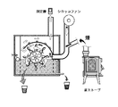
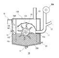
- FIG. 1 shows a vertical cross-sectional view of the air purifier 1A which is the first embodiment of the present invention.
- the air purifier 1A is a device for introducing and purifying a gas as a purification target such as exhaust from a combustion device, and fine droplets of the gas introduced into the gas-liquid contact chamber 10b inside the housing 10. It is a so-called water film type air purifier that purifies by adsorbing pollutants while exposing it to water.
- the storage tank 10a formed in the lower portion of the space formed inside the rectangular housing 10 to store the purification water 100, the droplet generation means for generating droplets, and the storage tank 10a.
- a gas-liquid contact chamber 10b formed above and serving as a space for purifying the gas introduced from the introduction pipe 11 is provided, and the purification water 100 stored in the storage tank 10a is brought into the gas-liquid contact chamber 10b by a droplet generation means. It is designed to be diffused in the form of fine droplets.
- the gas-liquid contact chamber 10b by introducing a gas such as exhaust from the wood stove 500 shown in FIG. 2 into the gas-liquid contact chamber 10b through the introduction pipe 11 and exposing the gas to the droplets diffused inside, the gas is contaminated.
- a method is adopted in which the substance is adsorbed on the droplets of purification water and removed. Further, the droplets adsorbing the pollutants are dropped from the gas-liquid contact chamber 10b to the purification water 100 stored in the storage tank 10a below the gas-liquid contact chamber 10a and stored, and the purified gas is above the gas-liquid contact chamber 10b. It is discharged to the outside through the arranged discharge tube 13.
- the droplet generating means in the present invention is an electric water turbine 21 that rotates a blade 22 while rotating a shaft 21 with an electric motor (not shown), and a part thereof is stored in a storage tank 10a.
- a storage tank 10a By rotating and driving the purification water 100 soaked to a predetermined depth from the water surface, fine droplets are generated and diffused evenly into the gas-liquid contact chamber 10b.
- Air is mixed into the purification water 100 stored in the storage tank 10a to diffuse fine bubbles, which is the greatest feature of the present invention.
- the purification water 100 stored in the storage tank 10a is agitated by the electric water wheel 20 to diffuse the droplets due to the droplets into the gas-liquid contact chamber 10b, and the blades 22 entrain the air in the purification water 100.
- it exerts a function of diffusing fine bubbles, and at the same time, it diffuses a large amount of fine droplets in the gas-liquid contact chamber 10b to adsorb pollutants in the gas, and at the same time, it is contained in the stored purification water 100.
- diffusing a large amount of fine bubbles it exerts the function of floating and separating pollutants on the water surface side.
- a drainage pipe 15 having a drainage port 15a opened to form a drain means is arranged at a predetermined level position in the storage tank 10a, and is shown in FIG. As shown, the amount of the stored purification water 100 exceeding the level is discharged to the outside. Further, the storage tank 10a is provided with a supply pipe 14 as a supply means for replenishing the purification water 100 by opening the valve 141 when the float 142 becomes equal to or lower than a predetermined level.
- the water bubbles are adhering to the contained pollutants and floated to the water surface side. It can be discharged to the outside from the drain pipe 15 through the discharge port 15a. Therefore, while minimizing the amount of replenishment of the purification water 100, the contaminated substances in the stored purification water 100 can be reliably separated and disposed of, and a clean state in which bacterial growth and odor generation are unlikely to occur is maintained. It is easy to do. Further, since the air mixed in the purification water 100 is a gas such as the introduced exhaust gas, there is also an action that pollutants contained in the gas that has become blisters are adsorbed and removed in the purification water 100. is doing.
- a sirocco fan 30A as a blowing means is attached to the base end side of the introduction pipe 11 for introducing the gas into the gas-liquid contact chamber 10b, and the gas discharged from the combustion device or the like is placed in the middle position on the downstream side thereof.
- the motor-driven water turbine 20 used is for a fish farm having a configuration as shown in the figure from the viewpoint of high stirring ability, splash generation ability, and foam generation ability.
- the water turbine is suitable, and in particular, as shown in FIG. 5 (only one blade 22 is displayed), the one in which many holes 220 are formed in each blade 22 is excellent in the ability to generate bubbles. It is optimal in that it is.
- the water turbine 20 having such a configuration is immersed in the purification water 100 stored in the storage tank 10a with about one-third of its diameter and rotated by an electric motor to entrain air in the purification water 100 and mix it. While doing so, a large amount of fine microbubbles having a diameter of 0.1 mm or less can be generated. Since such microbubbles are in a negatively charged state and easily adsorbed to fine pollutants in water, even if they are minute pollutants, they are relatively large and low due to the adhesion of many microbubbles. Since a complex of specific gravity is formed and floats on the water surface side, pollutants can be efficiently separated and removed from the purification water.
- the air purifier 1A of the present embodiment is introduced at a position above the gas-liquid contact chamber 10b of the housing 10 with a predetermined interval in the centrifugal direction of the water turbine 20.
- An arc-shaped partition wall 101 for restricting the flow direction of the gas is provided sideways so that efficient gas-liquid contact can be performed.
- vertical partition walls 102 and 103 are also provided on both the left and right sides of the gas-liquid contact chamber 10b (the storage tank 10a side is reticulated), so that the generated droplets can easily concentrate and contact the introduced gas. It has become.
- FIGS. 3 to 9 examples of the air purifier according to the present invention will be described in detail with reference to FIGS. 3 to 9.
- an air purifier similar to the above-described embodiment is actually created, and while introducing the exhaust (smoke) of a wood stove into the air purifier, the air purification function and the contaminated materials from the stored purification water are removed.
- the separation function was verified by conducting the following tests.
- Air cleaner Assuming that it has substantially the same structure as the air purifier 1A in FIG. 1, it is about 40% higher than the bottom inside a wooden housing (external size: 30 cm x 80 cm x 70 cm, plate thickness 1 cm) formed in a rectangular shape.
- a drain pipe is arranged so as to form a storage tank for storing purification water, and an electric water wheel for a fish farm is installed by inserting a rotating shaft from the outside at a position slightly above the water surface line of the storage tank. , About one-third of the diameter was arranged so as to be immersed in the purification water of the storage tank.
- the water turbine was driven by rotating a motor arranged outside the housing at 100 / RPM to operate the air purifier.
- the motor of the electric turbine is for three-phase 200V, but by connecting it from a single-layer 200V outlet via an inverter, it is possible to adjust the rotation speed while supplying power with three-phase 200V.
- a sirocco fan is placed on the base end side of the introduction pipe to introduce the exhaust, and the inlet pipe is connected so that the exhaust of the wood stove joins in the middle of the introduction path, and the tip side is in the gas-liquid contact chamber.
- the storage tank was opened near the water surface. Then, the sirocco fan was driven while burning the wood with the wood stove, and the exhaust (smoke) was introduced into the gas-liquid contact chamber.
- An air pollution measuring device air measuring instrument JSM-134, manufactured by Matobai Co., Ltd.
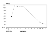
- the purified air discharged from the discharge tube is a fine particle substance (PM2.5) and HCHO (formaldehyde).
- TVOC chemical pollutant
- FIG. 6 is a graph of PM2.5 transition data
- FIG. 7 is a graph of MCHO transition data
- FIG. 8 is a graph of TVOC transition data
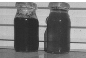
- FIG. 9 is A (right bottle) and B (left side bottle) in which purification water is collected. A comparative photograph of the bottle) is shown.
- the purification water A located in the middle layer of the storage tank is light brown and translucent to the back side
- the purification water B discharged from the water surface side is dark black and does not show through to the back side. It was found that the condition was such that components such as pollutants were collected and separated on the water surface side.
- the air purifier according to the present invention has a simple and compact configuration as described above, but purifies the introduced air by diffusing fine droplets into the gas-liquid separator by the rotational operation of the water turbine. In addition to demonstrating its function, it also has the function of separating and discharging contaminants that are captured by droplets and diffused in the purification water of the storage tank, and are lifted to the surface of the water by the action of fine bubbles. Became clear.
- the purifying water used in the above-mentioned embodiment is mixed with activated carbon in the form of fine powder to enhance the odor removing ability, but the air purifier of the present invention is in a state where activated carbon is not mixed. It has been found to exhibit excellent odor removal and air purification functions.
- activated carbon if a chlorine dioxide preparation for space sterilization is mixed with purification water, the function of removing and inactivating pathogens in the air can be further enhanced.
- FIG. 10 shows an air purifier 1B which is a second embodiment of the present invention.
- This air purifier 1B has almost the same configuration and function as the air purifier 1A of FIG. 1, but in addition to the configuration and function of the air purifier 1A described above, it is stored in the storage tank 10c.
- the purification water 200 is characterized in that it is lime water in which slaked lime (calcium hydroxide) is dissolved in water.
- the contained slaked lime contains carbon dioxide contained in the introduced gas. It is characterized by producing calcium carbonate while reacting with the gas, and it is possible to discharge the carbon dioxide from the discharge tube 13 in a state where the carbon dioxide concentration is greatly reduced from the introduced gas.
- the air purifier 1B in addition to contacting the introduced gas while diffusing lime water into fine droplets in the gas-liquid contact chamber 10b by the action of the water wheel 20, the air purifier 1B is located in the gas-liquid contact chamber 10b. Since the gas has a function of making fine bubbles and diffusing into the purification water 200 of the storage tank 10c and contacting with lime water, carbon dioxide in the gas in both the gas-liquid contact chamber 10b and the storage tank 10c. And calcium hydroxide in the purification water 200 reacts with each other, so that extremely high contact efficiency and reaction efficiency are realized.
- the housing 10B is provided with a lime supply means 16 capable of supplying quick lime (calcium oxide), slaked lime or an aqueous solution of calcium hydroxide into the storage tank 10c, and a supply pipe thereof.
- a method is adopted in which the purification water 200 is adjusted to lime water in an appropriate state while supplying any of these to the storage tank 10c side at a predetermined timing and amount.
- the administrator of the apparatus manually operates the lime supply means 16 as appropriate, and although not shown, the water for purifying water 200 such as a temperature sensor and a pH sensor arranged in the storage tank 10c is not shown.
- a predetermined control means may automatically adjust the supply timing and supply amount by feedback control based on the detection data transmitted from the means for detecting the state of. Further, the calcium carbonate generated in the purification water 200 is settled on the bottom side of the storage tank 10c in a cloudy state, and when this is accumulated to some extent, the valve 17 provided at the bottom of the storage tank 10c is opened. Therefore, the portion can be easily discarded or recovered.
- FIG. 11 shows an air purifier 1C as a modification of the above-mentioned air purifier 1B.
- the gas (smoke) discharged from the wood stove 500 or the like (not shown) is introduced into the air purifier 1C as an outdoor unit via the introduction pipe 11B while removing the wall with the insertion pipe 12B.
- the introduction pipe 11B is arranged vertically downward with the sirocco fan 30A arranged on the upper end side, and penetrates one end side of the partition wall 101 covering the upper part of the gas-liquid contact chamber 10b to allow gas to flow downward. It has come to be introduced.
- a hypochlorous acid aqueous solution may be used instead of the purification waters 100 and 200, and the purified gas may be returned to the room.
- bacteria and viruses contained in the introduced gas can be sterilized and inactivated with hypochlorous acid, and indoor air can be reliably purified.
- an air purifier capable of exhibiting excellent purification ability while being compact and low cost has been obtained.
- 1A, 1B, 1C air purifier 10,10B housing, 10a, 10c storage tank, 10b gas-liquid contact quality, 11,11B introduction pipe, 12,12B inlet pipe, 13 discharge pipe, 14,160 supply pipe, 15 , 15B drain pipe, 15a drain port, 16 lime supply means, 16B lime water tank, 17 valve, 20 water wheel, 21 shaft, 22 blades, 30A sirocco fan, 100, 200 purification water, 220 holes, 500 wood stove
Landscapes
- Chemical & Material Sciences (AREA)
- Engineering & Computer Science (AREA)
- Chemical Kinetics & Catalysis (AREA)
- Environmental & Geological Engineering (AREA)
- Analytical Chemistry (AREA)
- General Chemical & Material Sciences (AREA)
- Oil, Petroleum & Natural Gas (AREA)
- Biomedical Technology (AREA)
- Health & Medical Sciences (AREA)
- Life Sciences & Earth Sciences (AREA)
- Water Supply & Treatment (AREA)
- Hydrology & Water Resources (AREA)
- Organic Chemistry (AREA)
- Combustion & Propulsion (AREA)
- Mechanical Engineering (AREA)
- General Engineering & Computer Science (AREA)
- Sustainable Development (AREA)
- Disinfection, Sterilisation Or Deodorisation Of Air (AREA)
- Separation Of Particles Using Liquids (AREA)
Priority Applications (1)
| Application Number | Priority Date | Filing Date | Title |
|---|---|---|---|
| JP2022570049A JPWO2022131316A1 (https=) | 2020-12-18 | 2021-12-16 |
Applications Claiming Priority (4)
| Application Number | Priority Date | Filing Date | Title |
|---|---|---|---|
| JP2020-210617 | 2020-12-18 | ||
| JP2020210617 | 2020-12-18 | ||
| JP2021133225 | 2021-08-18 | ||
| JP2021-133225 | 2021-08-18 |
Publications (1)
| Publication Number | Publication Date |
|---|---|
| WO2022131316A1 true WO2022131316A1 (ja) | 2022-06-23 |
Family
ID=82059537
Family Applications (1)
| Application Number | Title | Priority Date | Filing Date |
|---|---|---|---|
| PCT/JP2021/046407 Ceased WO2022131316A1 (ja) | 2020-12-18 | 2021-12-16 | 空気清浄機 |
Country Status (2)
| Country | Link |
|---|---|
| JP (1) | JPWO2022131316A1 (https=) |
| WO (1) | WO2022131316A1 (https=) |
Cited By (2)
| Publication number | Priority date | Publication date | Assignee | Title |
|---|---|---|---|---|
| CN115990604A (zh) * | 2023-03-23 | 2023-04-21 | 西安峰盛智能电子有限公司 | 一种集成电路封装塑封抽风装置 |
| CN118270870A (zh) * | 2024-06-04 | 2024-07-02 | 西安国际医学中心有限公司 | 一种医用产科手术废液清理装置 |
Citations (10)
| Publication number | Priority date | Publication date | Assignee | Title |
|---|---|---|---|---|
| JPS51153756U (https=) * | 1975-06-02 | 1976-12-08 | ||
| JPS60212205A (ja) * | 1984-04-05 | 1985-10-24 | Kuken Kiko Kk | 湿式除塵装置 |
| JPH06253703A (ja) * | 1993-03-04 | 1994-09-13 | Yoshimi Ueshima | 曝気表層水の深層部への送り込み方法 |
| WO1998045031A1 (fr) * | 1997-04-10 | 1998-10-15 | Masakatsu Takayasu | Appareil melangeur |
| JP2000033216A (ja) * | 1998-07-15 | 2000-02-02 | Nec Home Electronics Ltd | ミスト発生装置 |
| CN203108363U (zh) * | 2013-03-08 | 2013-08-07 | 河南永兴锅炉集团有限公司 | 烟气动力离心水膜除尘装置 |
| CN104436939A (zh) * | 2014-11-18 | 2015-03-25 | 赵龙 | 甩液装置 |
| CN204522726U (zh) * | 2015-04-22 | 2015-08-05 | 宋远超 | 一种工业烟气处理装置 |
| CN210544080U (zh) * | 2019-05-16 | 2020-05-19 | 安徽鑫诺斯润滑科技有限公司 | 一种金属加工液生产车间用除尘装置 |
| KR102178220B1 (ko) * | 2020-03-11 | 2020-11-12 | 박기현 | 이동형 미세먼지 저감 장치 |
-
2021
- 2021-12-16 WO PCT/JP2021/046407 patent/WO2022131316A1/ja not_active Ceased
- 2021-12-16 JP JP2022570049A patent/JPWO2022131316A1/ja active Pending
Patent Citations (10)
| Publication number | Priority date | Publication date | Assignee | Title |
|---|---|---|---|---|
| JPS51153756U (https=) * | 1975-06-02 | 1976-12-08 | ||
| JPS60212205A (ja) * | 1984-04-05 | 1985-10-24 | Kuken Kiko Kk | 湿式除塵装置 |
| JPH06253703A (ja) * | 1993-03-04 | 1994-09-13 | Yoshimi Ueshima | 曝気表層水の深層部への送り込み方法 |
| WO1998045031A1 (fr) * | 1997-04-10 | 1998-10-15 | Masakatsu Takayasu | Appareil melangeur |
| JP2000033216A (ja) * | 1998-07-15 | 2000-02-02 | Nec Home Electronics Ltd | ミスト発生装置 |
| CN203108363U (zh) * | 2013-03-08 | 2013-08-07 | 河南永兴锅炉集团有限公司 | 烟气动力离心水膜除尘装置 |
| CN104436939A (zh) * | 2014-11-18 | 2015-03-25 | 赵龙 | 甩液装置 |
| CN204522726U (zh) * | 2015-04-22 | 2015-08-05 | 宋远超 | 一种工业烟气处理装置 |
| CN210544080U (zh) * | 2019-05-16 | 2020-05-19 | 安徽鑫诺斯润滑科技有限公司 | 一种金属加工液生产车间用除尘装置 |
| KR102178220B1 (ko) * | 2020-03-11 | 2020-11-12 | 박기현 | 이동형 미세먼지 저감 장치 |
Cited By (3)
| Publication number | Priority date | Publication date | Assignee | Title |
|---|---|---|---|---|
| CN115990604A (zh) * | 2023-03-23 | 2023-04-21 | 西安峰盛智能电子有限公司 | 一种集成电路封装塑封抽风装置 |
| CN115990604B (zh) * | 2023-03-23 | 2023-08-25 | 西安峰盛智能电子有限公司 | 一种集成电路封装塑封抽风装置 |
| CN118270870A (zh) * | 2024-06-04 | 2024-07-02 | 西安国际医学中心有限公司 | 一种医用产科手术废液清理装置 |
Also Published As
| Publication number | Publication date |
|---|---|
| JPWO2022131316A1 (https=) | 2022-06-23 |
Similar Documents
| Publication | Publication Date | Title |
|---|---|---|
| JP3222973U (ja) | 湿式空気清浄器 | |
| CN104321137B (zh) | 二氧化氯气体产生装置及医疗器具用杀菌盒 | |
| CN104279636B (zh) | 一种空气除味净化湿化装置及方法 | |
| WO2022131316A1 (ja) | 空気清浄機 | |
| KR102439949B1 (ko) | 습식 공기정화장치 | |
| CN113260444B (zh) | 空气净化装置 | |
| KR100901300B1 (ko) | 습건식 복합 탈취장치 | |
| JP4621095B2 (ja) | 空気清浄化装置 | |
| KR102303369B1 (ko) | 건축물,병원,학교,군대의 막사,공장,동물을 사육하는 축사,식물을 재배하는 농장,사무실,지하주차장,지하철,분진발생공장에서 발생시키는 비산먼지 제거기능 및 혐오성 냄새 및 비중이 가벼운 유해물질성 물질분자와 미세먼지제거 기능, 세균 및 바이러스 살균기능, 습도조절기능, 산소 및 음이온 발생 기능을 발휘하여 쾌적한 환경을 조성하여주는 자연친화적인 친환경 다기능 공기 정화시스템 | |
| KR102761439B1 (ko) | 수전해 라디칼을 이용한 공기 살균 및 정화 장치 | |
| KR20180019324A (ko) | 원심력을 통한 공기청정 가습장치 및 공기청정 가습방법 | |
| JP5287857B2 (ja) | 調湿装置 | |
| JP2011158104A (ja) | 加湿機 | |
| CN101360955A (zh) | 纯化限界房间中的空气的生物学方法及其设备 | |
| CN207187420U (zh) | 一种水溶式除尘除味装置 | |
| JP3986502B2 (ja) | 空気清浄システム | |
| KR20040058590A (ko) | 공기정화제를 구비한 공기청정기 | |
| KR20040105424A (ko) | 자외선램프를 구비한 음이온발생/습도조절 공기청정기 | |
| KR100773791B1 (ko) | 공기청정기 | |
| CN105879535A (zh) | 雾化洗涤式空气净化器 | |
| WO2020145165A1 (ja) | 空気浄化装置 | |
| KR102349868B1 (ko) | 공기청정가습 시계 | |
| CN219272537U (zh) | 用于空气清洗机的自动配液装置 | |
| KR100924063B1 (ko) | 물과 숯을 이용한 자동필터세척식 공기정화장치 | |
| JP3156762B2 (ja) | 室内空気清浄方法及びその装置 |
Legal Events
| Date | Code | Title | Description |
|---|---|---|---|
| 121 | Ep: the epo has been informed by wipo that ep was designated in this application |
Ref document number: 21906677 Country of ref document: EP Kind code of ref document: A1 |
|
| ENP | Entry into the national phase |
Ref document number: 2022570049 Country of ref document: JP Kind code of ref document: A |
|
| NENP | Non-entry into the national phase |
Ref country code: DE |
|
| 122 | Ep: pct application non-entry in european phase |
Ref document number: 21906677 Country of ref document: EP Kind code of ref document: A1 |