WO2022130895A1 - 回転コネクタ装置 - Google Patents
回転コネクタ装置 Download PDFInfo
- Publication number
- WO2022130895A1 WO2022130895A1 PCT/JP2021/042564 JP2021042564W WO2022130895A1 WO 2022130895 A1 WO2022130895 A1 WO 2022130895A1 JP 2021042564 W JP2021042564 W JP 2021042564W WO 2022130895 A1 WO2022130895 A1 WO 2022130895A1
- Authority
- WO
- WIPO (PCT)
- Prior art keywords
- flat cable
- flat
- connector device
- conductors
- fixed
- Prior art date
- Legal status (The legal status is an assumption and is not a legal conclusion. Google has not performed a legal analysis and makes no representation as to the accuracy of the status listed.)
- Ceased
Links
Images


Classifications
-
- H—ELECTRICITY
- H01—ELECTRIC ELEMENTS
- H01R—ELECTRICALLY-CONDUCTIVE CONNECTIONS; STRUCTURAL ASSOCIATIONS OF A PLURALITY OF MUTUALLY-INSULATED ELECTRICAL CONNECTING ELEMENTS; COUPLING DEVICES; CURRENT COLLECTORS
- H01R35/00—Flexible or turnable line connectors, i.e. the rotation angle being limited
- H01R35/02—Flexible line connectors without frictional contact members
- H01R35/025—Flexible line connectors without frictional contact members having a flexible conductor wound around a rotation axis
-
- H—ELECTRICITY
- H01—ELECTRIC ELEMENTS
- H01R—ELECTRICALLY-CONDUCTIVE CONNECTIONS; STRUCTURAL ASSOCIATIONS OF A PLURALITY OF MUTUALLY-INSULATED ELECTRICAL CONNECTING ELEMENTS; COUPLING DEVICES; CURRENT COLLECTORS
- H01R35/00—Flexible or turnable line connectors, i.e. the rotation angle being limited
- H01R35/04—Turnable line connectors with limited rotation angle with frictional contact members
-
- B—PERFORMING OPERATIONS; TRANSPORTING
- B60—VEHICLES IN GENERAL
- B60R—VEHICLES, VEHICLE FITTINGS, OR VEHICLE PARTS, NOT OTHERWISE PROVIDED FOR
- B60R16/00—Electric or fluid circuits specially adapted for vehicles and not otherwise provided for; Arrangement of elements of electric or fluid circuits specially adapted for vehicles and not otherwise provided for
- B60R16/02—Electric or fluid circuits specially adapted for vehicles and not otherwise provided for; Arrangement of elements of electric or fluid circuits specially adapted for vehicles and not otherwise provided for electric constitutive elements
- B60R16/023—Electric or fluid circuits specially adapted for vehicles and not otherwise provided for; Arrangement of elements of electric or fluid circuits specially adapted for vehicles and not otherwise provided for electric constitutive elements for transmission of signals between vehicle parts or subsystems
- B60R16/027—Electric or fluid circuits specially adapted for vehicles and not otherwise provided for; Arrangement of elements of electric or fluid circuits specially adapted for vehicles and not otherwise provided for electric constitutive elements for transmission of signals between vehicle parts or subsystems between relatively movable parts of the vehicle, e.g. between steering wheel and column
-
- H—ELECTRICITY
- H01—ELECTRIC ELEMENTS
- H01B—CABLES; CONDUCTORS; INSULATORS; SELECTION OF MATERIALS FOR THEIR CONDUCTIVE, INSULATING OR DIELECTRIC PROPERTIES
- H01B7/00—Insulated conductors or cables characterised by their form
- H01B7/08—Flat or ribbon cables
- H01B7/0861—Flat or ribbon cables comprising one or more screens
-
- H—ELECTRICITY
- H05—ELECTRIC TECHNIQUES NOT OTHERWISE PROVIDED FOR
- H05K—PRINTED CIRCUITS; CASINGS OR CONSTRUCTIONAL DETAILS OF ELECTRIC APPARATUS; MANUFACTURE OF ASSEMBLAGES OF ELECTRICAL COMPONENTS
- H05K1/00—Printed circuits
- H05K1/02—Details
- H05K1/0213—Electrical arrangements not otherwise provided for
- H05K1/0216—Reduction of cross-talk, noise or electromagnetic interference
- H05K1/0218—Reduction of cross-talk, noise or electromagnetic interference by printed shielding conductors, ground planes or power plane
-
- H—ELECTRICITY
- H01—ELECTRIC ELEMENTS
- H01R—ELECTRICALLY-CONDUCTIVE CONNECTIONS; STRUCTURAL ASSOCIATIONS OF A PLURALITY OF MUTUALLY-INSULATED ELECTRICAL CONNECTING ELEMENTS; COUPLING DEVICES; CURRENT COLLECTORS
- H01R13/00—Details of coupling devices of the kinds covered by groups H01R12/70 or H01R24/00 - H01R33/00
- H01R13/646—Details of coupling devices of the kinds covered by groups H01R12/70 or H01R24/00 - H01R33/00 specially adapted for high-frequency, e.g. structures providing an impedance match or phase match
- H01R13/6473—Impedance matching
-
- H—ELECTRICITY
- H01—ELECTRIC ELEMENTS
- H01R—ELECTRICALLY-CONDUCTIVE CONNECTIONS; STRUCTURAL ASSOCIATIONS OF A PLURALITY OF MUTUALLY-INSULATED ELECTRICAL CONNECTING ELEMENTS; COUPLING DEVICES; CURRENT COLLECTORS
- H01R2201/00—Connectors or connections adapted for particular applications
- H01R2201/26—Connectors or connections adapted for particular applications for vehicles
-
- H—ELECTRICITY
- H05—ELECTRIC TECHNIQUES NOT OTHERWISE PROVIDED FOR
- H05K—PRINTED CIRCUITS; CASINGS OR CONSTRUCTIONAL DETAILS OF ELECTRIC APPARATUS; MANUFACTURE OF ASSEMBLAGES OF ELECTRICAL COMPONENTS
- H05K2201/00—Indexing scheme relating to printed circuits covered by H05K1/00
- H05K2201/07—Electric details
- H05K2201/0707—Shielding
- H05K2201/0723—Shielding provided by an inner layer of PCB
Definitions
- the present invention relates to a rotary connector device used as a steering roll connector.
- the conventional rotary connector device is formed by covering a fixed-side member, a rotary-side member that is rotatable with respect to the fixed-side member, and a conductor with an insulating material, and is formed between the fixed-side member and the rotary-side member.
- a plurality of flat cables that are accommodated in a state of being stacked in an annular accommodating space are known (see, for example, Patent Document 1).
- a rotary connector device for example, it is required to suppress deterioration of electromagnetic compatibility due to electromagnetic noise and destabilization of impedance of a conductor for a communication circuit, which are problems when used for multiple high-speed communication of CAN (Controller Area Network). Be done.
- CAN Controller Area Network
- the rotary connector device of Patent Document 1 integrally forms a flat cable having a conductor for a communication circuit and a dummy flat cable having no conductor, and a dummy flat cable is provided between the flat cables having adjacent conductors. By interposing, it suppresses the deterioration of electromagnetic compatibility due to electromagnetic noise and the destabilization of the impedance of the conductor for the communication circuit of the flat cable. Therefore, in the rotary connector device of Patent Document 1, the overall thickness direction dimension of the plurality of flat cables becomes large, and the device may become large in size.
- An object of the present invention is to provide a rotary connector device capable of suppressing the increase in size of the device, reducing the electromagnetic compatibility, and stabilizing the impedance.
- the rotary connector device is formed by covering a fixed-side member, a rotary-side member that is rotatable with respect to the fixed-side member, and a conductor with an insulating material, and the fixed-side member and the rotary-side member.
- a rotary connector device including a plurality of flat cables accommodated in a state of being stacked in an annular accommodation space formed between the above, including at least a target conductor among the plurality of flat cables.
- a shield film is disposed between the flat cable and the flat cable adjacent to the flat cable including the conductor of interest.
- the shield film is integrally formed with the flat cable including the target conductor.
- the shield film is arranged at least in a portion where the target conductor is located in the width direction of the flat cable including the target conductor.
- the shield film is integrally formed on one surface side of each of the plurality of flat cables.
- the rotary connector device according to the present invention is formed by depositing silver on a resin film of the shield film.
- the impedance of the target conductor can be stabilized by the shield film, so that the increase in size of the apparatus can be suppressed. At the same time, it is possible to achieve electromagnetic compatibility and stabilize impedance.
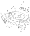
- FIG. 1 is a perspective view of the rotary connector device according to the first embodiment of the present invention
- FIG. 2 is a perspective view illustrating the inside of the rotary connector device
- FIG. 3 is a plan view illustrating the inside of the rotary connector device.
- FIG. 4 is a cross-sectional view illustrating the first to fourth flat cables of FIG. 3
- FIG. 5 is a cross-sectional view illustrating the first flat cable.
- the rotary connector device 1 of the present embodiment is used as a so-called steering roll connector provided at a connecting portion between the steering column on the vehicle body side and the steering shaft on the steering wheel side.
- the rotary connector device 1 transmits an electric signal between a main ECU provided on the vehicle body side and a steering ECU provided on the steering wheel side for controlling electrical components arranged on the steering wheel side. It constitutes a part of a communication circuit for the purpose, and also constitutes a part of another conductive circuit for transmitting electric power and electric signals between the vehicle body side and the steering wheel side.
- the communication circuit performs high-speed communication of, for example, 100 Mbps or more.
- the rotary connector device 1 has a fixed-side housing 10 as a fixed-side member fixed to the steering column, and a rotary connector fixed to the steering shaft and rotatably provided with respect to the fixed-side housing 10. It includes a rotating side housing 20 as a side member, and a plurality of flat cables 30 accommodated in an annular accommodating space S formed between the fixed side housing 10 and the rotating side housing 20.
- the fixed-side housing 10 has a fixed-side ring portion 11 provided with an opening through which a steering shaft can be inserted, and a cylindrical outer peripheral cylindrical portion 12 extending vertically from the outer peripheral side of the fixed-side ring portion 11. ..
- the first fixed-side connector 13 to which one end of a part of the flat cables 30 is connected and one end of the other flat cables 30 are connected to the outer peripheral portion of the outer peripheral cylindrical portion 12.
- a second fixed-side connector 14 is provided.
- the rotating side housing 20 is arranged so as to face the fixed side ring portion 11, and is arranged so as to face the rotating side ring portion 21 provided with an opening through which the steering shaft can be inserted and the outer peripheral cylindrical portion 12, and rotates. It has a cylindrical inner peripheral cylindrical portion 22 extending vertically from the inner peripheral side of the side ring portion 21.
- a first rotating side connector 23 to which the other end of a part of the flat cable 30 to which one end is connected to the first fixed side connector 13 is connected, and a second fixed side connector.
- a second rotation-side connector 24 to which the other end of the flat cable 30 to which one end is connected is provided is provided.
- the accommodation space S is formed in an annular shape by being partitioned by the fixed side ring portion 11 and the outer peripheral cylindrical portion 12 of the fixed side housing 10, the rotating side ring portion 21 of the rotating side housing 20, and the inner peripheral cylindrical portion 22.
- the plurality of flat cables 30 are each formed in a strip shape having the same widthwise dimension.
- Each of the plurality of flat cables 30 is formed as a separate body, and is housed in the storage space S in a state of being separably overlapped.
- one end of each of the plurality of flat cables 30 is fixed to the outer peripheral cylindrical portion 12, and one end of the rotating side housing 20 is rotated along the inner peripheral surface of the outer peripheral cylindrical portion 12.
- Each intermediate portion is inverted so as to form a U shape between the outer peripheral cylindrical portion 12 and the inner peripheral cylindrical portion 22 and wound in the other direction in the rotation direction, and the other end of each is wound.
- the portion is fixed to the inner peripheral cylindrical portion 22.
- the plurality of flat cables 30 are composed of first to fourth flat cables 31, 32, 33, 34 (hereinafter referred to as 31 to 34).
- first to fourth flat cables 31 to 34 a plurality of conductors 31a, 32a, 33a, 34a (hereinafter referred to as 31a to 34a) arranged at intervals in the width direction are used as insulating materials 31b, respectively. It is formed in a band shape by being covered with 32b, 33b, 34b (hereinafter referred to as 31b to 34b).
- the first to fourth flat cables 31 to 34 accommodated in the accommodation space S have the first flat cable 31, the first flat cable 31, from the outer peripheral cylindrical portion 12 side toward the inner peripheral cylindrical portion 22 side on the radial outer side.
- the two flat cables 32, the third flat cable 33, and the fourth flat cable 34 are separably stacked in this order.
- the first to fourth flat cables 31 to 34 accommodated in the accommodation space S are the first flat cable 31 and the second flat cable 31 from the inner peripheral cylindrical portion 22 side to the outer peripheral cylindrical portion 12 side in the radial direction.
- the flat cable 32, the third flat cable 33, and the fourth flat cable 34 are in a separably laminated state in this order. Further, as shown in FIG.
- the first to fourth flat cables 31 to 34 accommodated in the accommodation space S move to their intermediate portions as the rotating side housing 20 rotates with respect to the fixed side housing 10.
- U-turn portions 31c, 32c, 33c, 34c (hereinafter referred to as 31c to 34c) are formed. Therefore, when the U-turn portions 31c to 34c are located at the center of each of the first to fourth flat cables 31 to 34 in the longitudinal direction, the rotating side housing 20 is unidirectionally and with respect to the fixed side housing 10. Allows rotation of the same angle in each of the other directions.
- At least the first flat cable 31 including the conductors for the first and second communication circuits described later as the target conductors and the first flat cable 31 are adjacent to each other.
- a shield film 35 having a property of blocking or absorbing electromagnetic waves and suppressing the influence of electromagnetic waves on the conductors for the first and second communication circuits is arranged between the second flat cable 32 and the second flat cable 32. It is set up.
- the conductors for the first and second communication circuits as the target conductors are conductors used as a differential transmission line.
- the shield film 35 may be arranged between each of the plurality of flat cables 30.
- the shield film 35 is arranged only between the first flat cable 31 including the conductor for the communication circuit and the second flat cable 32.
- the shield film 35 may be integrally formed with either the first flat cable 31 or the second flat cable 32 between the first flat cable 31 and the second flat cable 32. In this embodiment, the shield film 35 is integrally formed with the first flat cable 31.
- the first flat cable 31 includes, as a plurality of conductors 31a, conductors 31a1, 31a2, 31a3, 31a4 (hereinafter referred to as 31a1 to 31a4) for the first to fourth conductive circuits, and conductors 31a5 for the first and second communication circuits. , 31a6, first and second ground conductors 31a7, 31a8. As shown in FIG. 5, the first flat cable 31 has a first conductive circuit conductor 31a1, a first ground conductor 31a7, and a first communication circuit conductor from the left end to the right end in the width direction.
- the first flat cable 31 is used for high-speed communication by disposing the first and second ground conductors 31a7, 31a8 on the outer sides of the first and second communication circuit conductors 31a5 and 31a6 in the width direction, respectively. It constitutes the GSSG structure of.
- the conductors 31a1 to 31a4 for the first to fourth conductive circuits are formed in a rectangular cross section having a width direction dimension of 0.8 mm or more and a thickness direction dimension of 35 ⁇ m. Further, the conductors 31a5 and 31a6 for the first and second communication circuits and the conductors 31a7 and 31a8 for the first and second grounds are formed in a rectangular cross section having a width direction dimension of 0.1 mm and a thickness direction dimension of 35 ⁇ m, respectively. ing.
- the first and second communication circuit conductors 31a5, 31a6 and the first and second ground conductors 31a7, 31a8 are the distance between the first ground conductor 31a7 and the first communication circuit conductor 31a5, and the first communication circuit conductor.
- the distance between the 31a5 and the second communication circuit conductor 31a6 and the distance between the second communication circuit conductor 31a6 and the second ground conductor 31a8 are arranged so as to be 0.4 mm or more and 1 mm or less, respectively.
- the first insulating layer 31b1 is composed of a resin film 31b2 having a thickness of 12 ⁇ m such as PET (polyethylene terephthalate) and an adhesive layer 31b3 having a thickness of 20 ⁇ m.
- the second insulating layer 31b4 is composed of a resin film 31b5 having a thickness of 25 ⁇ m and an adhesive layer 31b6 having a thickness of 20 ⁇ m.
- a shield film 35 is disposed on the outer surface of the second insulating layer 31b4 of the first flat cable 31 (the surface facing the second flat cable 32).
- the shield film 35 is bonded to a resin film 35a such as PET (polyethylene terephthalate) having a thickness of 9 ⁇ m, a silver film 35b having a thickness of 0.2 ⁇ m deposited on the resin film 35a, and a thickness of 20 ⁇ m. It is composed of an agent layer 35c.
- the silver film 35b is arranged in the width direction of the first flat cable 31 with the same size as the gap between the first and second ground conductors 31a7 and 31a8, and is at least the conductors 31a5 for the first and second communication circuits. It suffices to have a width dimension that covers the entire 31a6 from the second flat cable 32 side.
- the distance between the first and second communication circuit conductors 31a5 and 31a6 is set so that the impedance of the first and second communication circuit conductors 31a5 and 31a6 is within the range of 90 ⁇ or more and 110 ⁇ or less.
- the distance between the conductors 31a5 and 31a6 for the first and second communication circuits and the conductors 31a7 and 31a8 for the first and second grounds, and the distance between the conductors 31a5 and 31a6 for the first and second communication circuits and the silver film 35b are set. ..
- the number of the plurality of flat cables 30 partially stacked is different in the state of being accommodated in the accommodation space S.
- the portion a in FIG. 3 has four laminated sheets. be.
- the portion b in FIG. 3 is located inside the accommodation space S in the radial direction with respect to the portion a and the radius around which the plurality of flat cables 30 are wound is smaller than that of the portion a, the portion b is one of the plurality of flat cables 30.
- the portion is wound around one or more turns, and the number of laminated sheets is six.
- the portion c in FIG. 3 is a U-turn portion 31c of the first flat cable 31, and the number of laminated sheets is one.
- the number of laminated first to fourth flat cables 31 to 34 in the accommodation space S changes in each portion according to the rotation position of the rotation side housing 20 with respect to the fixed side housing 10. For example, in FIG. 3, when the rotating side housing 20 is rotated clockwise with respect to the fixed side housing 10, the number of stacked flat cables wound on the radial outer side changes in a direction of increasing. Further, the number of stacked flat cables wound on the inner side in the radial direction changes in a direction of decreasing. Further, the portion of the first to fourth flat cables 31 to 34 having one laminated number between one end and the other end moves clockwise in the accommodation space S.
- the impedances of the conductors 31a5 and 31a6 for the first and second communication circuits of the first flat cable 31 change with each change of the inductance and the capacitance.
- the second to fourth flat cables 32, 33, and 34 move toward and away from the first flat cable 31, so that the first and second communication can be performed.
- the inductance and capacitance of the circuit conductors 31a5 and 31a6 may change, but the shield film 35 provided on the first flat cable 31 affects the electromagnetic waves of the second to fourth flat cables 32, 33, 34. Since it is suppressed, it becomes possible to stabilize the impedance of the conductors 31a5 and 31a6 for the first and second communication circuits.
- the conductors 31a5 for the first and second communication circuits The impedance of 31a6 dropped by 2 ⁇ .
- the second to fourth flat cables 32, 33, 34 are used for one of the first flat cables 31 and for the first flat cable 31.
- the impedance of the first and second communication circuit conductors 31a5 and 31a6 decreased by 41 ⁇ .
- the second to fourth flat cables 32, 33 with respect to the conductors 31a5 and 31a6 for the first and second communication circuits, are provided by the shield film 35 disposed between the first flat cable 31 and the second flat cable 32.
- the influence of the electromagnetic waves of 34 was suppressed, and the impedances of the conductors 31a5 and 31a6 for the first and second communication circuits were stabilized.
- the fixed side housing 10, the rotary side housing 20 rotatable with respect to the fixed side housing 10, and the conductor are formed and fixed by covering the conductor with an insulating material.
- a rotary connector device 1 comprising a plurality of flat cables 30 stacked in an annular accommodation space S formed between a side housing 10 and a rotation side housing 20 and accommodated in a state of being laminated, wherein the plurality of flat cables are provided.
- a shield film 35 is located between at least the first flat cable 31 including the first and second communication circuit conductors 31a5 and 31a6 and the second flat cable 32 adjacent to the first flat cable 31. Are arranged.
- the shield film 35 makes it possible to stabilize the impedances of the conductors 31a5 and 31a6 for the first and second communication circuits. It is possible to suppress the increase in size of the device, achieve electromagnetic compatibility, and stabilize the impedance.
- the electromagnetic compatibility means that the electromagnetic interference wave radiated from the target electric device does not affect other electric devices, and the electromagnetic interference wave radiated from the other electric device is received. Also refers to the property that the target electrical equipment is not affected.
- the shield film 35 is integrally formed with the first flat cable 31 including the conductors 31a5 and 31a6 for the first and second communication circuits.
- the first flat cable 31 and the shield film 35 can be made into one component, so that the number of components can be reduced and the assembly man-hours can be reduced.
- the shield film 35 is arranged at a portion in the width direction of the first flat cable 31 where at least the conductors 31a5 and 31a6 for the first and second communication circuits are located.
- the shield film 35 is formed by depositing silver on the resin film 35a.
- the thickness dimension of the silver film 35b can be reduced, so that the thickness direction dimension of the entire shield film 35 can be reduced, and the thickness direction of the first flat cable 31 can be increased. It becomes possible to suppress it.
- FIG. 6 shows a second embodiment of the present invention, and is a cross-sectional view of the first to fourth flat cables.
- the same components as those in the above embodiment are designated by the same reference numerals.
- the shield film 35 is provided on one surface of each of the first to fourth flat cables 31 to 34.
- the conductors 32a and 33a of the second and third flat cables 32 and 33 among the stacked first to fourth flat cables 31 to 34 are on both sides in the stacking direction.
- the shield film 35 will be disposed of.
- the shield film 35 provides the first and second positions. Since the impedances of the second communication circuit conductors 31a5 and 31a6 can be stabilized, it is possible to suppress the increase in size of the device, achieve electromagnetic compatibility, and stabilize the impedance.
- the shield film 35 is integrally formed on one surface side of each of the plurality of flat cables 30.
- the rotary connector device of the present invention is applied to the steering roll connector, but the present invention is not limited to this.
- the rotary connector device of the present invention can be applied to a rotary mechanism such as a joint portion of a robot arm.
- one end is connected to a fixed side member, a rotary moving side member that moves while rotating with respect to the fixed side member, and the fixed side member, and the other end is connected to the rotary moving side member.
- a plurality of flat cables are connected and wound around a rotary moving side member, and a signal or power is required to be transmitted between the fixed side member and the rotary moving side member, for example. It can be applied to vehicle slide seats, slide doors, and the like.
- the shield film in which the silver film is formed by depositing silver on the resin film is shown, but the present invention is not limited to this. If it is possible to suppress the influence of electromagnetic waves on the conductor of the first flat cable 31, for example, a shield film is formed by forming a copper film or an aluminum film on a resin film instead of a silver film. May be good.
- the first and second communication circuit conductors 31a5 and 31a6, which are conductors for suppressing the influence of electromagnetic waves, are attached to the first flat cable 31 located at the end of the flat cable 30 in the stacking direction.
- the arrangement is shown, but it is not limited to this.
- the conductor to be suppressed by the influence of electromagnetic waves does not need to be placed on the flat cable located at the end in the stacking direction.
- the present invention can also be applied to the case of arranging the conductors.
- a shield film may be arranged between the flat cable in which the target conductor located in the intermediate portion is arranged and the flat cables adjacent to both sides in the stacking direction.
- Rotating connector device 10 Fixed side housing 20 Rotating side housing 30 Flat cable 31 1st flat cable 31a Conductor 31a5 1st communication circuit conductor 31a6 2nd communication circuit conductor 32 2nd flat cable 32a Conductor 33 3rd flat cable 33a Conductor 34 4th flat cable 34a Conductor 35 Shield film 35a Resin film S Storage space
Landscapes
- Engineering & Computer Science (AREA)
- Mechanical Engineering (AREA)
- Physics & Mathematics (AREA)
- Electromagnetism (AREA)
- Microelectronics & Electronic Packaging (AREA)
- Insulated Conductors (AREA)
- Details Of Connecting Devices For Male And Female Coupling (AREA)
Priority Applications (5)
| Application Number | Priority Date | Filing Date | Title |
|---|---|---|---|
| EP21906258.5A EP4254685B8 (en) | 2020-12-15 | 2021-11-19 | Rotating connector device |
| KR1020237018607A KR102822553B1 (ko) | 2020-12-15 | 2021-11-19 | 회전 커넥터 장치 |
| CN202180078948.7A CN116472204A (zh) | 2020-12-15 | 2021-11-19 | 旋转连接器装置 |
| JP2022569802A JPWO2022130895A1 (https=) | 2020-12-15 | 2021-11-19 | |
| US18/324,293 US12506310B2 (en) | 2020-12-15 | 2023-05-26 | Rotating connector device |
Applications Claiming Priority (2)
| Application Number | Priority Date | Filing Date | Title |
|---|---|---|---|
| JP2020-207887 | 2020-12-15 | ||
| JP2020207887 | 2020-12-15 |
Related Child Applications (1)
| Application Number | Title | Priority Date | Filing Date |
|---|---|---|---|
| US18/324,293 Continuation US12506310B2 (en) | 2020-12-15 | 2023-05-26 | Rotating connector device |
Publications (1)
| Publication Number | Publication Date |
|---|---|
| WO2022130895A1 true WO2022130895A1 (ja) | 2022-06-23 |
Family
ID=82058742
Family Applications (1)
| Application Number | Title | Priority Date | Filing Date |
|---|---|---|---|
| PCT/JP2021/042564 Ceased WO2022130895A1 (ja) | 2020-12-15 | 2021-11-19 | 回転コネクタ装置 |
Country Status (6)
| Country | Link |
|---|---|
| US (1) | US12506310B2 (https=) |
| EP (1) | EP4254685B8 (https=) |
| JP (1) | JPWO2022130895A1 (https=) |
| KR (1) | KR102822553B1 (https=) |
| CN (1) | CN116472204A (https=) |
| WO (1) | WO2022130895A1 (https=) |
Cited By (3)
| Publication number | Priority date | Publication date | Assignee | Title |
|---|---|---|---|---|
| JPWO2023248537A1 (https=) * | 2022-06-21 | 2023-12-28 | ||
| JP2024053780A (ja) * | 2022-10-04 | 2024-04-16 | 古河電気工業株式会社 | フラットケーブル組立体および回転コネクタ装置 |
| WO2025023173A1 (ja) * | 2023-07-21 | 2025-01-30 | 古河電気工業株式会社 | フレキシブルフラットケーブルおよび給電装置 |
Families Citing this family (1)
| Publication number | Priority date | Publication date | Assignee | Title |
|---|---|---|---|---|
| KR102801462B1 (ko) | 2023-12-27 | 2025-04-25 | 주식회사 현대케피코 | 차량용 전자 제어 장치 |
Citations (5)
| Publication number | Priority date | Publication date | Assignee | Title |
|---|---|---|---|---|
| JP2005039870A (ja) * | 2003-05-21 | 2005-02-10 | Toyoda Mach Works Ltd | スパイラルケーブル装置 |
| JP2005339833A (ja) * | 2004-05-24 | 2005-12-08 | Sony Chem Corp | フレキシブルフラットケーブル |
| JP2008029179A (ja) * | 2006-07-25 | 2008-02-07 | Toyota Motor Corp | 電気接続装置 |
| WO2014017649A1 (ja) | 2012-07-26 | 2014-01-30 | 古河電気工業株式会社 | 回転コネクタ装置 |
| JP2015201312A (ja) * | 2014-04-07 | 2015-11-12 | 住友電気工業株式会社 | 高速伝送フレキシブルフラットケーブル用多層樹脂シート及び高速伝送フレキシブルフラットケーブル |
Family Cites Families (5)
| Publication number | Priority date | Publication date | Assignee | Title |
|---|---|---|---|---|
| US6969807B1 (en) * | 2004-07-20 | 2005-11-29 | Advanced Flexible Circuits Co., Ltd. | Planar type flexible cable with shielding structure |
| JP2009181804A (ja) * | 2008-01-30 | 2009-08-13 | Hitachi Cable Ltd | シールド付き伝送線路 |
| JP5823380B2 (ja) * | 2010-04-28 | 2015-11-25 | 古河電気工業株式会社 | 回転コネクタ装置 |
| TWM482829U (zh) | 2014-01-28 | 2014-07-21 | wei-sheng Zhang | 柔性扁平排線 |
| DE102014118027B4 (de) * | 2014-12-05 | 2024-05-23 | Valeo Schalter Und Sensoren Gmbh | Anordnung von Flachleitern in einer Wickelfeder-Kassette sowie Wickelfeder-Kassette |
-
2021
- 2021-11-19 WO PCT/JP2021/042564 patent/WO2022130895A1/ja not_active Ceased
- 2021-11-19 JP JP2022569802A patent/JPWO2022130895A1/ja active Pending
- 2021-11-19 CN CN202180078948.7A patent/CN116472204A/zh active Pending
- 2021-11-19 KR KR1020237018607A patent/KR102822553B1/ko active Active
- 2021-11-19 EP EP21906258.5A patent/EP4254685B8/en active Active
-
2023
- 2023-05-26 US US18/324,293 patent/US12506310B2/en active Active
Patent Citations (5)
| Publication number | Priority date | Publication date | Assignee | Title |
|---|---|---|---|---|
| JP2005039870A (ja) * | 2003-05-21 | 2005-02-10 | Toyoda Mach Works Ltd | スパイラルケーブル装置 |
| JP2005339833A (ja) * | 2004-05-24 | 2005-12-08 | Sony Chem Corp | フレキシブルフラットケーブル |
| JP2008029179A (ja) * | 2006-07-25 | 2008-02-07 | Toyota Motor Corp | 電気接続装置 |
| WO2014017649A1 (ja) | 2012-07-26 | 2014-01-30 | 古河電気工業株式会社 | 回転コネクタ装置 |
| JP2015201312A (ja) * | 2014-04-07 | 2015-11-12 | 住友電気工業株式会社 | 高速伝送フレキシブルフラットケーブル用多層樹脂シート及び高速伝送フレキシブルフラットケーブル |
Non-Patent Citations (1)
| Title |
|---|
| See also references of EP4254685A4 |
Cited By (3)
| Publication number | Priority date | Publication date | Assignee | Title |
|---|---|---|---|---|
| JPWO2023248537A1 (https=) * | 2022-06-21 | 2023-12-28 | ||
| JP2024053780A (ja) * | 2022-10-04 | 2024-04-16 | 古河電気工業株式会社 | フラットケーブル組立体および回転コネクタ装置 |
| WO2025023173A1 (ja) * | 2023-07-21 | 2025-01-30 | 古河電気工業株式会社 | フレキシブルフラットケーブルおよび給電装置 |
Also Published As
| Publication number | Publication date |
|---|---|
| KR102822553B1 (ko) | 2025-06-18 |
| US12506310B2 (en) | 2025-12-23 |
| EP4254685B8 (en) | 2025-11-26 |
| JPWO2022130895A1 (https=) | 2022-06-23 |
| EP4254685A4 (en) | 2024-04-17 |
| US20230307880A1 (en) | 2023-09-28 |
| EP4254685B1 (en) | 2025-10-15 |
| CN116472204A (zh) | 2023-07-21 |
| KR20230118826A (ko) | 2023-08-14 |
| EP4254685A1 (en) | 2023-10-04 |
Similar Documents
| Publication | Publication Date | Title |
|---|---|---|
| WO2022130895A1 (ja) | 回転コネクタ装置 | |
| JP5823380B2 (ja) | 回転コネクタ装置 | |
| US4912283A (en) | Shielding tape for telecommunications cables and a cable including same | |
| EP3010684B1 (en) | A rotary joint of a robot and the robot including the same | |
| JP7196909B2 (ja) | シールドフラットケーブル | |
| US5329064A (en) | Superior shield cable | |
| US10381136B2 (en) | Signal transmission cable | |
| ES3008582T3 (en) | Cable having shielding tape wth conductive shielding segments | |
| JP6005156B2 (ja) | 回転コネクタ装置 | |
| US20230013560A1 (en) | Electric cable | |
| US6386886B1 (en) | Gimbal system | |
| CN112688074A (zh) | 基于多层结构的可调信号雷达罩 | |
| KR20210052454A (ko) | 회전 커넥터 장치 | |
| JP2005039870A (ja) | スパイラルケーブル装置 | |
| WO2023248537A1 (ja) | 回転コネクタ | |
| JP2025070025A (ja) | 配線構造体および給電装置 | |
| US10777942B2 (en) | Signal transmission cable | |
| US12131844B2 (en) | Cable | |
| WO2024176754A1 (ja) | ケーブル及びケーブルの製造方法 | |
| JP2022160063A (ja) | 回転コネクタの回転量検出装置、回転量検出方法および回転量検出プログラム | |
| EP3326385B1 (en) | Low capacitance, shielded, watertight device interconnect | |
| TW201351449A (zh) | 軟性標準排線與電路板的整合排線結構 | |
| JP2025069509A (ja) | 平板状電線の接続構造 | |
| WO2024157396A1 (ja) | シールドフラットケーブル | |
| JPS58225507A (ja) | 遮蔽通信ケ−ブル |
Legal Events
| Date | Code | Title | Description |
|---|---|---|---|
| 121 | Ep: the epo has been informed by wipo that ep was designated in this application |
Ref document number: 21906258 Country of ref document: EP Kind code of ref document: A1 |
|
| ENP | Entry into the national phase |
Ref document number: 2022569802 Country of ref document: JP Kind code of ref document: A |
|
| WWE | Wipo information: entry into national phase |
Ref document number: 202180078948.7 Country of ref document: CN |
|
| ENP | Entry into the national phase |
Ref document number: 2021906258 Country of ref document: EP Effective date: 20230627 |
|
| NENP | Non-entry into the national phase |
Ref country code: DE |
|
| WWG | Wipo information: grant in national office |
Ref document number: 2021906258 Country of ref document: EP |