WO2022130856A1 - ドリルヘッド及びドリル - Google Patents
ドリルヘッド及びドリル Download PDFInfo
- Publication number
- WO2022130856A1 WO2022130856A1 PCT/JP2021/041746 JP2021041746W WO2022130856A1 WO 2022130856 A1 WO2022130856 A1 WO 2022130856A1 JP 2021041746 W JP2021041746 W JP 2021041746W WO 2022130856 A1 WO2022130856 A1 WO 2022130856A1
- Authority
- WO
- WIPO (PCT)
- Prior art keywords
- flute
- ridge
- mounting surface
- straight line
- circumferential direction
- Prior art date
- Legal status (The legal status is an assumption and is not a legal conclusion. Google has not performed a legal analysis and makes no representation as to the accuracy of the status listed.)
- Ceased
Links
Images



Classifications
-
- B—PERFORMING OPERATIONS; TRANSPORTING
- B23—MACHINE TOOLS; METAL-WORKING NOT OTHERWISE PROVIDED FOR
- B23B—TURNING; BORING
- B23B51/00—Tools for drilling machines
- B23B51/0006—Drills with cutting inserts
- B23B51/0007—Drills with cutting inserts with exchangeable cutting insert
-
- B—PERFORMING OPERATIONS; TRANSPORTING
- B23—MACHINE TOOLS; METAL-WORKING NOT OTHERWISE PROVIDED FOR
- B23B—TURNING; BORING
- B23B51/00—Tools for drilling machines
- B23B51/0002—Drills with connected cutting heads, e.g. with non-exchangeable cutting heads; Drills with a single insert extending across the rotational axis and having at least two radially extending cutting edges in the working position
- B23B51/0003—Drills with connected cutting heads, e.g. with non-exchangeable cutting heads; Drills with a single insert extending across the rotational axis and having at least two radially extending cutting edges in the working position with exchangeable heads or inserts
- B23B51/0004—Drills with connected cutting heads, e.g. with non-exchangeable cutting heads; Drills with a single insert extending across the rotational axis and having at least two radially extending cutting edges in the working position with exchangeable heads or inserts with cutting heads or inserts attached by screw means
-
- B—PERFORMING OPERATIONS; TRANSPORTING
- B23—MACHINE TOOLS; METAL-WORKING NOT OTHERWISE PROVIDED FOR
- B23B—TURNING; BORING
- B23B2200/00—Details of cutting inserts
- B23B2200/16—Supporting or bottom surfaces
- B23B2200/161—Supporting or bottom surfaces with projections
-
- B—PERFORMING OPERATIONS; TRANSPORTING
- B23—MACHINE TOOLS; METAL-WORKING NOT OTHERWISE PROVIDED FOR
- B23B—TURNING; BORING
- B23B51/00—Tools for drilling machines
- B23B51/02—Twist drills
Definitions
- Patent Document 1 International Publication No. 2002/005990 describes a drill.
- the drill of Patent Document 1 has a cutting head and a holder.
- the cutting head has a bearing surface.
- the holder has a front surface.
- a plurality of protrusions extending along the radial direction are formed on the bearing surface. Each of the plurality of protrusions becomes higher toward the outside in the radial direction.
- a plurality of recesses are formed on the front surface along the radial direction. Each of the recesses becomes deeper toward the outside in the radial direction.
- the cutting head is attached to the holder by fitting each of the plurality of protrusions into each of the plurality of recesses.
- the drill head of the present disclosure is rotated around the central axis.
- the drill head has a first mounting surface mounted on the holder, a head tip surface on the opposite side of the first mounting surface in the axial direction along the central axis, and a head outer peripheral surface connected to the first mounting surface and the head tip surface.
- a first flute and a second flute extending spirally around the central axis are formed on the outer peripheral surface of the head so as to reach the first mounting surface from the tip surface of the head.
- the first flute and the second flute are formed symmetrically with respect to the central axis.
- each of the first flute and the second flute is a circumference along the circumference centered on the central axis.
- the first mounting surface has a first end and a second end facing each other at intervals in the direction.
- the first mounting surface is formed with a first ridge, a second ridge, and a third ridge extending along a radial direction orthogonal to the axial direction.
- the first ridge is located between the first end of the first flute and the second end of the second flute in the circumferential direction.
- the second and third ridges are located between the second end of the first flute and the first end of the second flute in the circumferential direction.
- the second ridge is closer to the second end of the first flute than the third ridge in the circumferential direction.
- the angle between the virtual straight line passing through the center of the first convex line in the circumferential direction and the virtual straight line passing through the center axis and the first end of the first flute is the virtual straight line passing through the center of the first convex line in the circumferential direction and the central axis. And the angle formed by the virtual straight line passing through the second end of the second flute.
- FIG. 1 is a perspective view of the drill 100.
- FIG. 2 is a front view of the drill head 10.
- FIG. 3 is a rear view of the drill head 10.
- FIG. 4 is a side view of the drill head 10.
- FIG. 5 is a front view of the holder 20.
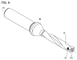
- FIG. 6 is a perspective view of the holder 20.
- FIG. 7 is an enlarged perspective view of the drill 100.
- the tool balance is determined by the distance from the central axis to the mass and the arrangement of the mass in the cross section perpendicular to the central axis of the rotary tool.
- Good tool balance means that the centrifugal force applied to the rotating tool when the rotating tool is rotated at a predetermined rotation speed is small. Maintaining the tool balance means that the tool balance is good even if the outer diameter of the rotating tool is small.
- the present disclosure provides a drill head capable of maintaining the stability of support by the holder and the tool balance even when the outer diameter becomes small.
- the drill head according to the embodiment is rotated around the central axis.
- the drill head has a first mounting surface mounted on the holder, a head tip surface on the opposite side of the first mounting surface in the axial direction along the central axis, and a head outer peripheral surface connected to the first mounting surface and the head tip surface.
- a first flute and a second flute extending spirally around the central axis are formed on the outer peripheral surface of the head so as to reach the first mounting surface from the tip surface of the head.
- the first flute and the second flute are formed symmetrically with respect to the central axis.
- each of the first flute and the second flute is along the circumference centered on the central axis.
- the first mounting surface has a first end and a second end facing each other at intervals in the circumferential direction.
- the first mounting surface is formed with a first ridge, a second ridge, and a third ridge extending along a radial direction orthogonal to the axial direction.
- the first ridge is located between the first end of the first flute and the second end of the second flute in the circumferential direction.
- the second and third ridges are located between the second end of the first flute and the first end of the second flute in the circumferential direction.
- the second ridge is closer to the second end of the first flute than the third ridge in the circumferential direction.
- the angle between the virtual straight line passing through the center of the first convex line in the circumferential direction and the virtual straight line passing through the center axis and the first end of the first flute is the virtual straight line passing through the center of the first convex line in the circumferential direction and the central axis. And the angle formed by the virtual straight line passing through the second end of the second flute.
- the angle between the virtual straight line passing through the center of the first convex line in the circumferential direction and the virtual straight line passing through the central axis and the first end of the first flute is 30 ° or more and 70 °. It may be less than or equal to °.
- the angle formed by the virtual straight line passing through the center of the first ridge in the circumferential direction and the virtual straight line passing through the center of the second ridge in the circumferential direction is 150 °. It may be 170 ° or more, and the angle between the virtual straight line passing through the center of the first convex line in the circumferential direction and the virtual straight line passing through the center of the third convex line in the circumferential direction is 150 ° or more and 170 ° or less. You may.
- the angle formed by the virtual straight line passing through the center of the second ridge in the circumferential direction and the virtual straight line passing through the center of the third ridge in the circumferential direction is 20 ° or more and 60 ° or less. May be.
- the tool balance is improved by the arrangement of the first ridge, the second ridge and the third ridge in the circumferential direction approaching the uniform arrangement.
- the first flute is the first flute and the head.
- the line of intersection with the outer peripheral surface may be twisted so as to extend clockwise from the second end of the first flute along the circumferential direction.
- the angle between the virtual straight line passing through the center of the second convex line in the circumferential direction and the virtual straight line passing through the center axis and the second end of the first flute is the virtual straight line passing through the center of the third convex line in the circumferential direction and the central axis. And may be larger than the angle formed by the straight line passing through the first end of the second flute.
- the stress applied to the groove fitted to the second ridge and the stress applied to the groove fitted to the third ridge are equalized, so that the stress is fitted to the second ridge. It is possible to prevent the wear from being unevenly distributed in the groove.
- the width of the first ridge may be 1.1 times or more and 2.0 times or less the width of the second ridge and the width of the third ridge.
- the stress applied to the groove fitted to the first ridge and the stress applied to the groove fitted to the second ridge and the groove fitted to the third ridge are equalized. Therefore, it is possible to prevent the wear from being biased to the groove fitted in the first convex strip.
- the drill according to one aspect of the present disclosure includes a holder and the drill heads (1) to (6) above.
- the holder has a second mounting surface that is in contact with the first mounting surface.
- a first groove, a second groove, and a third groove extending along the radial direction are formed on the second mounting surface.
- the first groove, the second groove and the third groove are fitted to the first ridge, the second ridge and the third ridge, respectively.
- the drill according to another aspect of the present disclosure includes a drill head, a holder, and a fixing member.
- the drill head has a first mounting surface mounted on the holder, a head tip surface on the opposite side of the first mounting surface in the axial direction along the central axis of the drill head, and a head outer circumference connected to the first mounting surface and the head tip surface. It has a surface and a shank shaft extending from the first mounting surface along the axial direction.
- a first flute and a second flute extending spirally around the central axis are formed on the outer peripheral surface of the head so as to reach the first mounting surface from the tip surface of the head.
- the first flute and the second flute are formed symmetrically with respect to the central axis.
- each of the first flute and the second flute is along the circumference centered on the central axis.
- the first mounting surface has a first end and a second end facing each other at intervals in the circumferential direction.
- the first mounting surface is formed with a first ridge, a second ridge, and a third ridge extending along a radial direction orthogonal to the axial direction.
- the first ridge is located between the first end of the first flute and the second end of the second flute in the circumferential direction.
- the second and third ridges are located between the second end of the first flute and the first end of the second flute in the circumferential direction.
- the second ridge is closer to the second end of the first flute than the third ridge in the circumferential direction.
- the angle between the virtual straight line passing through the center of the first convex line in the circumferential direction and the virtual straight line passing through the center of the second convex line in the circumferential direction is the virtual straight line passing through the center of the first convex line in the circumferential direction and the virtual straight line in the circumferential direction. It is larger than the angle formed by the virtual straight line passing through the center of the third ridge.
- a notch is formed in the shank shaft.
- the holder has a second mounting surface in contact with the first mounting surface and a holder outer peripheral surface connected to the second mounting surface.
- the second mounting surface is formed with a first hole into which the shank shaft is inserted, and a first groove, a second groove, and a third groove extending along the radial direction.
- the first groove, the second groove and the third groove are fitted to the first ridge, the second ridge and the third ridge, respectively.
- a second hole connected to the first hole is formed on the outer peripheral surface of the holder.
- the fixing member is in contact with the notch by being inserted into the second hole.
- the shank shaft by attaching the first mounting surface to the second mounting surface, the shank shaft can be positioned at a position where it can be fixed by using the fixing member.
- drill 100 The configuration of the drill (hereinafter referred to as “drill 100”) according to the embodiment will be described.
- FIG. 1 is a perspective view of the drill 100.
- the drill 100 has a drill head 10, a holder 20, and a fixing member 30.
- the drill 100 is rotated around the central axis A to perform cutting.
- the drill head 10 is made of, for example, a cemented carbide.
- the holder 20 and the fixing member 30 are made of, for example, steel.
- the drill head 10 is on the tip end side of the drill 100 and the holder 20 is on the proximal end side of the drill 100 in the direction along the central axis A.
- the base end side of the drill 100 is on the opposite side of the tip side of the drill 100 in the direction along the central axis A.
- the drill 100 is rotated around the central axis A by being attached to the spindle of the machine tool in the holder 20.
- FIG. 2 is a front view of the drill head 10.
- FIG. 3 is a rear view of the drill head 10.
- FIG. 4 is a side view of the drill head 10. As shown in FIGS. 2, 3 and 4, the drill head 10 has a first mounting surface 11, a head tip surface 12, and a head outer peripheral surface 13.
- the first mounting surface 11 and the head tip surface 12 are end faces of the drill head 10 in the axial direction.
- the drill head 10 is attached to the holder 20 on the first attachment surface 11.
- the head tip surface 12 is located at the tip of the drill 100.
- the head tip surface 12 is the opposite surface of the first mounting surface 11 in the axial direction.
- the head outer peripheral surface 13 is connected to the first mounting surface 11 and the head tip surface 12.
- the first flute 14 and the second flute 15 are formed on the outer peripheral surface 13 of the head.
- the head outer peripheral surface 13 is recessed toward the central axis A1 in the portion where the first flute 14 and the second flute 15 are formed.
- the first flute 14 and the second flute 15 extend spirally around the central axis A1 so as to reach the first mounting surface 11 from the head tip surface 12.
- the first flute 14 and the second flute 15 are formed in a shape symmetrical with respect to the central axis A1.
- the first flute 14 and the second flute 15 are the first mounting surface from the head tip surface 12 when viewed from the head tip surface 12 side along the axial direction. As it advances to 11, it is twisted clockwise. From another point of view, the first flute and the second flute are twisted to the right. From yet another point of view, the first flute and the second flute are formed in a spiral shape.
- the head tip surface 12 has a flank surface 12a and a flank surface 12b.
- the flank 12a and the first flute 14 intersect.
- the flank 12b and the second flute 15 intersect.
- the crossing ridge line between the flank 12a and the first flute 14 is a cutting edge 16
- the crossing ridge line between the flank surface 12b and the second flute 15 is a cutting edge 17.
- the cutting edge 16 and the cutting edge 17 extend from the outer peripheral surface 13 of the head toward the center of the tip surface 12 of the head (the tip of the drill 100).
- the work material (chips) cut by the cutting edge 16 and the cutting edge 17 is discharged through the first flute 14 and the second flute 15, respectively. That is, the first flute 14 and the second flute 15 are grooves formed for the discharge of chips.
- the first flute 14 has a first end 14a and a second end 14b.
- the second end 14b faces the first end 14a at a distance in the circumferential direction.
- the second end 14b is continuous with the end of the cutting edge 16 on the head outer peripheral surface 13 side. ..
- the second flute 15 has a first end 15a and a second end 15b.
- the second end 15b faces the first end 15a at a distance in the circumferential direction.
- the second end 15b is continuous with the end of the cutting edge 17 on the head outer peripheral surface 13 side. ..
- the first ridge 11a, the second ridge 11b, and the third ridge 11c are formed on the first mounting surface 11.
- the first ridge 11a, the second ridge 11b and the third ridge 11c extend along the radial direction.
- the first ridge 11a, the second ridge 11b, and the third ridge 11c extend from the outer peripheral surface 13 of the head toward the central axis A1 side.
- the first ridge 11a, the second ridge 11b, and the third ridge 11c project from the first mounting surface 11 along the axial direction.
- the first ridge 11a is located between the first end 14a of the first flute 14 and the second end 15b of the second flute 15 in the circumferential direction.
- the second ridge 11b and the third ridge 11c are located between the second end 14b of the first flute 14 and the first end 15a of the second flute 15 in the circumferential direction.
- the second ridge 11b is closer to the second end 14b of the first flute 14 than the third ridge 11c.
- the first ridge 11a, the second ridge 11b and the third ridge 11c are formed asymmetrically with respect to the central axis A1.
- a virtual straight line passing through the center of the first ridge 11a in the circumferential direction on the first mounting surface 11 is referred to as a virtual straight line VL1.
- the virtual straight line passing through the center in the circumferential direction of the second ridge 11b is referred to as a virtual straight line VL2
- the virtual straight line passing through the center in the circumferential direction of the third ridge 11c is referred to as a virtual straight line VL3.
- the virtual straight line VL1, the virtual straight line VL2, and the virtual straight line VL3 are orthogonal to the central axis A1.
- the virtual straight line passing through the first end 14a of the first flute 14 and the central axis A1 is referred to as a virtual straight line VL4.
- the virtual straight line passing through the second end 14b of the first flute 14 and the central axis A1 is referred to as a virtual straight line VL5.
- the virtual straight line passing through the first end 15a of the second flute 15 and the central axis A1 is referred to as a virtual straight line VL6.
- the virtual straight line passing through the second end 15b of the second flute 15 and the central axis A1 is referred to as a virtual straight line VL7.
- the virtual straight line VL4, the virtual straight line VL5, the virtual straight line VL6, and the virtual straight line VL7 are orthogonal to the central axis A1.
- the angle ⁇ 1 formed by the virtual straight line VL1 and the virtual straight line VL4 is equal to the angle ⁇ 2 formed by the virtual straight line VL1 and the virtual straight line VL7.
- a minute angle error between the angle ⁇ 1 and the angle ⁇ 2 is allowed.
- the angle ⁇ 1 and the angle ⁇ 2 are, for example, 30 ° or more and 70 ° or less.
- the angle ⁇ 3 formed by the virtual straight line VL1 and the virtual straight line VL2 is larger than the angle ⁇ 4 formed by the virtual straight line VL1 and the virtual straight line VL3. That is, it is preferable that the second ridge 11b and the third ridge 11c are formed asymmetrically with respect to the virtual straight line VL1.
- the angle ⁇ 3 and the angle ⁇ 4 are preferably 150 ° or more and 170 ° or less.
- the angle ⁇ 5 formed by the virtual straight line VL2 and the virtual straight line VL3 is preferably 20 ° or more and 60 ° or less.
- the total of the angle ⁇ 3, the angle ⁇ 4, and the angle ⁇ 5 is 360 °.
- the first flute 14 and the second flute 15 are formed in a clockwise spiral shape when viewed from the head tip surface 12 side. Therefore, when the first mounting surface 11 is viewed along the central axis A1 and in the direction from the first mounting surface 11 toward the head tip surface 12, the first flute 14 includes the first flute 14 and the head outer peripheral surface 13. Line of intersection (CL1 in FIG. 3) is twisted so as to extend clockwise from the second end 14b of the first flute 14 along the circumferential direction. Similarly, in the second flute 15, the line of intersection (CL2 in FIG. 3) between the second flute 15 and the head outer peripheral surface 13 extends clockwise from the second end 15b of the second flute 15 in the circumferential direction. Twisted like.
- the angle ⁇ 6 formed by the virtual straight line VL2 and the virtual straight line VL5 is preferably larger than the angle ⁇ 7 formed by the virtual straight line VL3 and the virtual straight line VL6.
- the width of the first ridge 11a, the width of the second ridge 11b, and the width of the third ridge 11c are the first width, the second width, and the third width, respectively.
- the first width, the second width, and the third width are widths in the direction orthogonal to the extending direction of the respective ridges, and are measured at the end of each ridge on the outer peripheral surface 13 side of the head.
- the first width is preferably larger than the second and third widths. More specifically, the first width is preferably 1.1 times or more and 2.0 times or less the second width and the third width.
- the second width is, for example, equal to the third width.
- a shank shaft 18 is formed on the first mounting surface 11.
- the shank shaft 18 extends along the axial direction from the center of the first mounting surface 11. Except for the portion where the notch 18a described later is formed, the cross section orthogonal to the axial direction of the shank axis 18 is, for example, a circle.
- a notch 18a is formed on the outer peripheral surface of the shank shaft 18.
- the notch 18a has an inclined surface 18b.
- the inclined surface 18b is inclined with respect to the axial direction (the direction in which the shank shaft 18 extends). More specifically, the normal vector of the inclined surface 18b is V1, and is from the tip of the shank shaft 18 (the end opposite to the first mounting surface 11) to the base end of the shank shaft 18 (the first mounting surface 11). When the unit vector in the direction toward the side end) is V2, the angle formed by V1 and V2 is smaller than 90 °.
- the area of the cross section of the shank axis 18 that intersects the inclined surface 18b and is orthogonal to the axial direction of the shank axis 18 is shank from the tip side of the shank axis 18 along the central axis A1. It decreases monotonically toward the proximal end side of the shaft 18.
- the outer diameter of the drill head 10 is defined as the outer diameter D.
- the outer diameter D is the diameter of the circumscribed circle of the drill head 10 when viewed from the head tip surface 12 side along the axial direction.
- the outer diameter D is preferably 15 mm or less.
- the outer diameter D is, for example, 6 mm or more.
- FIG. 5 is a front view of the holder 20.
- FIG. 6 is a perspective view of the holder 20. As shown in FIGS. 5 and 6, the holder 20 extends along the axial direction.
- the holder 20 has a second mounting surface 21 and a holder outer peripheral surface 22.
- the holder 20 is rotated around the central axis A2.
- the central axis A2 coincides with the central axis A.
- the second mounting surface 21 is the end surface of the holder 20 in the axial direction.
- a first groove 21a, a second groove 21b, and a third groove 21c are formed on the second mounting surface 21.
- the first groove 21a, the second groove 21b, and the third groove 21c extend along the radial direction.
- the first groove 21a, the second groove 21b, and the third groove 21c extend from the head outer peripheral surface 13 toward the center side of the second mounting surface 21.
- the first groove 21a, the second groove 21b, and the third groove 21c are recessed from the second mounting surface 21 along the axial direction.
- the holder outer peripheral surface 22 is connected to the second mounting surface 21.
- a flute 23 and a flute 24 are formed on the outer peripheral surface 22 of the holder.
- the outer peripheral surface 22 of the holder is recessed toward the central axis A2 in the portion where the flute 23 and the flute 24 are formed.
- the flute 23 and the flute 24 are formed in a spiral shape around the central axis of the holder 20.
- the flute 23 and the flute 24 extend from the second mounting surface 21 toward the proximal end side of the drill 100.
- the flute 23 and the flute 24 are twisted in the same direction as the first flute 14 and the second flute 15 when viewed from the second mounting surface 21 side. That is, the flute 23 and the flute 23 are twisted clockwise when viewed from the second mounting surface 21 side.
- the flute 23 and the flute 24 are connected to the first flute 14 and the second flute 15, respectively.
- the flute 23 has a first end 23a and a second end 23b.
- the second end 23b faces the first end 23a at a distance in the circumferential direction.
- the first end 23a is the circumferential end of the flute 23 corresponding to the first end 14a
- the second end 23b is the circumferential end of the flute 23 corresponding to the second end 14b.
- the flute 24 has a first end 24a and a second end 24b.
- the second end 24b faces the first end 24a at a distance in the circumferential direction.
- the first end 24a is the circumferential end of the flute 24 corresponding to the first end 15a
- the second end 24b is the circumferential end of the flute 24 corresponding to the second end 15b.
- the first groove 21a is located between the first end 23a of the flute 23 and the second end 24b of the flute 24 in the circumferential direction.
- the second groove 21b and the third groove 21c are located between the second end 23b of the flute 23 and the first end 24a of the flute 24 in the circumferential direction. In the circumferential direction, the second groove 21b is closer to the second end 23b of the flute 23 than the third groove 21c. From another point of view, the first groove 21a, the second groove 21b and the third groove 21c are formed asymmetrically with respect to the central axis A2.
- the virtual straight line passing through the center of the first groove 21a in the circumferential direction on the second mounting surface 21 is referred to as a virtual straight line VL8.
- the virtual straight line passing through the center in the circumferential direction of the second groove 21b is referred to as a virtual straight line VL9.
- the virtual straight line passing through the center in the circumferential direction of the third groove 21c is referred to as a virtual straight line VL10.
- the virtual straight line VL8, the virtual straight line VL9, and the virtual straight line VL10 are orthogonal to the central axis A2, respectively.
- the virtual straight line passing through the first end 23a of the flute 23 and the central axis A2 on the second mounting surface 21 is referred to as a virtual straight line VL11.
- the virtual straight line passing through the second end 23b of the flute 23 and the central axis A2 is referred to as a virtual straight line VL12.
- the virtual straight line passing through the first end 24a of the flute 24 and the central axis A2 is referred to as a virtual straight line VL13.
- the virtual straight line passing through the second end 24b of the flute 24 and the central axis A2 is referred to as a virtual straight line VL14.
- the virtual straight line VL11, the virtual straight line VL12, the virtual straight line VL13, and the virtual straight line VL14 are orthogonal to the central axis A2, respectively.
- the angle ⁇ 8 formed by the virtual straight line VL8 and the virtual straight line VL11 and the angle ⁇ 9 formed by the virtual straight line VL8 and the virtual straight line VL14 are equal to the angle ⁇ 1 and the angle ⁇ 2, respectively.
- the angle ⁇ 10 formed by the virtual straight line VL8 and the virtual straight line VL9 and the angle ⁇ 11 formed by the virtual straight line VL8 and the virtual straight line VL10 are equal to the angle ⁇ 4 and the angle ⁇ 5, respectively.
- the first groove 21a faces the first ridge 11a
- the second groove 21b and the third groove 21c face the second ridge 11b and the third ridge 11c, respectively.
- the angle ⁇ 12 formed by the virtual straight line VL9 and the virtual straight line VL10 is equal to the angle ⁇ 5.
- the first groove 21a, the second groove 21b, and the third groove 21c have a shape that can be fitted with the first ridge 11a, the second ridge 11b, and the third ridge 11c, respectively. Therefore, the first mounting surface 11 is placed on the second mounting surface so that the first groove 21a, the second groove 21b, and the third groove 21c face the first ridge 11a, the second ridge 11b, and the third ridge 11c, respectively.
- the drill head 10 is attached to the holder 20 by contacting the 21.
- the flute 23 and the flute 24 are formed in a clockwise spiral shape when viewed from the second mounting surface 21 side. Therefore, when the second mounting surface 21 is viewed along the central axis A2 and in the direction from the second mounting surface 21 toward the proximal end side of the holder 20 (that is, the proximal end side of the drill 100), the flute 23 receives the flute 23.
- the line of intersection between the flute 23 and the outer peripheral surface 22 of the holder is twisted so as to extend clockwise from the first end 23a of the flute 23 along the circumferential direction.
- the flute 24 is twisted so that the line of intersection between the flute 24 and the holder outer peripheral surface 22 extends clockwise from the first end 24a of the flute 24 in the circumferential direction.
- the angle ⁇ 13 formed by the virtual straight line VL9 and the virtual straight line VL12 and the angle ⁇ 14 formed by the virtual straight line VL10 and the virtual straight line VL13 are equal to the angle ⁇ 6 and the angle ⁇ 7, respectively.
- the width of the first groove 21a, the width of the second groove 21b, and the width of the third groove 21c are the fourth width, the fifth width, and the sixth width, respectively.
- the fourth width, the fifth width, and the sixth width are widths in a direction orthogonal to the extending direction of each groove, and are measured at the end of each groove on the holder outer peripheral surface 22 side.
- the fourth width is preferably larger than the fifth width and the sixth width. More specifically, the fourth width is preferably 1.1 times or more and 2.0 times or less the fifth width and the sixth width.
- the fifth width is, for example, equal to the sixth width.
- the first hole 21d is formed on the second mounting surface 21.
- the first hole 21d is formed in the central portion of the second mounting surface 21.
- the first hole 21d extends along the axial direction.
- a second hole 25 is formed on the outer peripheral surface 22 of the holder.
- the second hole 25 is connected to the first hole 21d.
- the second hole 25 extends in a direction intersecting the inclined surface 18b. When the holder outer peripheral surface 22 is viewed along the extending direction of the second hole 25, the inclined surface 18b is exposed from the second hole 25.
- a fixing member 30 is inserted in the second hole 25. More specifically, a thread groove is formed on the inner wall surface of the second hole 25, and the fixing member 30 is a bolt having a thread formed on the shaft.
- the fixing member 30 is inserted into the second hole 25 by turning the fixing member 30 into the second hole 25.
- the fixing member 30 advances in the second hole 25 along the extending direction of the second hole 25 and comes into contact with the inclined surface 18b.
- the shank shaft 18 is pulled toward the tip end (the end opposite to the second mounting surface 21) of the first hole 21d, and the drill head 10 is fixed to the holder 20.
- the drill head 10 On the first mounting surface 11, the first ridge 11a fitted into the first groove 21a, the second ridge 11b fitted into the second groove 21b, and the third ridge fitted into the third groove 21c. 11c is formed. Therefore, the drill head 10 is supported at three points in a state of being attached to the holder 20. Therefore, the drill head 10 is stably supported by the holder 20.
- the three ridges (first ridge 11a, second ridge 11b and third ridge 11c) formed on the first mounting surface 11 and the second mounting surface 21 are formed. Since the drill head 10 is supported by the holder 20 by three-point support by the three grooves (first groove 21a, second groove 21b, and third groove 21c), it is stable even when the outer diameter of the drill head 10 is small. Can be supported by.
- the angle ⁇ 1 and the angle ⁇ 2 are equal. Further, in the holder 20, the angle ⁇ 8 and the angle ⁇ 9 are equal to the angle ⁇ 1 and the angle ⁇ 2, respectively. That is, in the drill 100, the first ridge 11a is arranged between the first flute 14 and the second flute 15 in the circumferential direction, and the first groove 21a is intermediate between the flute 23 and the flute 24 in the circumferential direction. It will be placed in. Therefore, according to the drill 100, the tool balance can be maintained.
- the angle ⁇ 3 and the angle ⁇ 4 are 150 ° or more and 170 ° or less (when the angle ⁇ 5 is 20 ° or more and 60 ° or less), the first ridge 11a, the second ridge 11b and the third ridge 11c (first).
- the arrangement of the grooves 21a, the second groove 21b and the third groove 21c) in the circumferential direction becomes close to the uniform arrangement. Therefore, in this case, the tool balance of the drill 100 is further improved.
- FIG. 7 is an enlarged perspective view of the drill 100.
- the second is along the central axis A2 and in the direction DR from the second mounting surface 21 toward the base end side of the holder 20 (that is, the base end side of the drill 100).
- the flute 23 is twisted so that the line of intersection between the flute 23 and the holder outer peripheral surface 22 extends clockwise from the first end 23a of the flute 23 in the circumferential direction.
- the flute 24 is twisted so that the line of intersection between the flute 24 and the holder outer peripheral surface 22 extends clockwise from the first end 24a of the flute 24 in the circumferential direction.
- the wall thickness in the vicinity of the second groove 21b with respect to the flute 23 is smaller than the wall thickness in the vicinity of the third groove 21c with respect to the flute 24. More specifically, the thickness T23, which is the shortest distance between the deepest portion of the second groove 21b along the directional DR and the flute 23, is the shortest between the deepest portion of the third groove 21c along the directional DR and the flute 24. It is smaller than the distance T24 (not shown). Therefore, the stress in the vicinity of the second groove 21b tends to be larger than the stress in the vicinity of the third groove 21c.
- the angle ⁇ 6 is made larger than the angle ⁇ 7 in the drill head 10, and when the angle ⁇ 13 is larger than the angle ⁇ 14 in the holder 20, the second groove with respect to the flute 23.
- the wall thickness in the circumferential direction and the axial direction in the vicinity of 21b becomes large. Therefore, in this case, the stress applied to the second groove 21b is relaxed. As a result, it is possible to prevent the wear from being biased toward the second groove 21b.
- a cutting force is supported by one groove (first groove 21a) between the first end 23a of the flute 23 and the second end 24b of the flute 24, and the second end 23b of the flute 23 and the second end 24b of the flute 24 are supported. Since the cutting force is supported by the two grooves (second groove 21b and third groove 21c) between the one end 24a and the first groove 21a, the first groove 21a has more than the second groove 21b and the third groove 21c. Stress is easily applied. Therefore, when the first width is larger than the second width and the third width (the fourth width is larger than the fifth width and the sixth width), the stress in the vicinity of the first groove 21a is relaxed. As a result, it is possible to prevent the wear from being biased toward the first groove 21a.
- first ridge 11a There is one ridge (first ridge 11a) between the first end 14a of the first flute 14 and the second end 15b of the second flute 15, and the second end 14b and the first of the first flute 14. 2
- second ridge 11b and third ridge 11c There are two ridges (second ridge 11b and third ridge 11c) between the flute 15 and the first end 15a. Therefore, the arrangement of the first ridge 11a, the second ridge 11b and the third ridge 11c is asymmetric with respect to the central axis A1.
- the angle ⁇ 3 and the angle ⁇ 4 are different from each other, the arrangement of the second ridge 11b and the third ridge 11c becomes asymmetric with respect to the virtual straight line VL1.
- the drill head 10 is attached to the holder 20 except when the first ridge 11a, the second ridge 11b, and the third ridge 11c are fitted into the first groove 21a, the second groove 21b, and the third groove 21c, respectively. Cannot be installed.
- the first ridge 11a, the second ridge 11b, and the third ridge 11c enable the drill head 10 to be positioned with respect to the holder 20.
- the inclined surface 18b is always exposed from the second hole 25, so that the fixing member 30 pulls in and fixes the drill head 10. It is not necessary to form the notches 18a at a plurality of places. That is, it is possible to suppress a decrease in rigidity of the shank shaft 18 due to the formation of the notch 18a.
Landscapes
- Engineering & Computer Science (AREA)
- Mechanical Engineering (AREA)
- Drilling Tools (AREA)
Priority Applications (4)
| Application Number | Priority Date | Filing Date | Title |
|---|---|---|---|
| JP2022528720A JP7148038B1 (ja) | 2020-12-16 | 2021-11-12 | ドリルヘッド及びドリル |
| US17/801,265 US12377474B2 (en) | 2020-12-16 | 2021-11-12 | Drill head and drill |
| CN202180066749.4A CN116323058B (zh) | 2020-12-16 | 2021-11-12 | 钻头头部及钻头 |
| EP21906220.5A EP4265360A4 (en) | 2020-12-16 | 2021-11-12 | DRILL HEAD AND DRILL BIT |
Applications Claiming Priority (2)
| Application Number | Priority Date | Filing Date | Title |
|---|---|---|---|
| JP2020208320 | 2020-12-16 | ||
| JP2020-208320 | 2020-12-16 |
Publications (1)
| Publication Number | Publication Date |
|---|---|
| WO2022130856A1 true WO2022130856A1 (ja) | 2022-06-23 |
Family
ID=82059704
Family Applications (1)
| Application Number | Title | Priority Date | Filing Date |
|---|---|---|---|
| PCT/JP2021/041746 Ceased WO2022130856A1 (ja) | 2020-12-16 | 2021-11-12 | ドリルヘッド及びドリル |
Country Status (5)
| Country | Link |
|---|---|
| US (1) | US12377474B2 (https=) |
| EP (1) | EP4265360A4 (https=) |
| JP (1) | JP7148038B1 (https=) |
| CN (1) | CN116323058B (https=) |
| WO (1) | WO2022130856A1 (https=) |
Families Citing this family (2)
| Publication number | Priority date | Publication date | Assignee | Title |
|---|---|---|---|---|
| JP1715996S (ja) * | 2021-08-27 | 2022-05-27 | ドリルホルダ | |
| JP1715995S (ja) * | 2021-08-27 | 2022-05-27 | ドリルヘッド |
Citations (8)
| Publication number | Priority date | Publication date | Assignee | Title |
|---|---|---|---|---|
| WO2002005990A1 (en) | 2000-07-14 | 2002-01-24 | Sumitomo Electric Industries, Ltd. | Throw-away cutting tool |
| JP2005161462A (ja) * | 2003-12-02 | 2005-06-23 | Sumitomo Electric Hardmetal Corp | スローアウェイ式ドリル |
| DE102006005880A1 (de) * | 2006-02-06 | 2007-08-09 | Hartmetall-Werkzeugfabrik Paul Horn Gmbh | Schneidwerkzeug für spanende Bearbeitung |
| US20070274794A1 (en) * | 2006-05-26 | 2007-11-29 | Cirino Thomas J | Oblique angle serration location and drive interface |
| JP2009523073A (ja) * | 2006-01-13 | 2009-06-18 | マパル ファブリック フュール プラツィジョンズベルクゼウグ ドクトル.クレス カーゲー | 工具システム |
| JP2011005631A (ja) * | 2009-06-23 | 2011-01-13 | Sandvik Intellectual Property Ab | 切り屑除去機械加工用回転工具及びそのルーズトップ |
| JP2016508889A (ja) * | 2013-03-06 | 2016-03-24 | アライド マシーン アンド エンジニアリング コーポレーションAllied Machine & Engineering Corporation | 深穴のためのドリルシステム |
| WO2017150459A1 (ja) * | 2016-03-04 | 2017-09-08 | 住友電工ハードメタル株式会社 | 切削工具 |
Family Cites Families (4)
| Publication number | Priority date | Publication date | Assignee | Title |
|---|---|---|---|---|
| SE510533C2 (sv) * | 1996-11-04 | 1999-05-31 | Seco Tools Ab | Verktyg för skärande bearbetning |
| SE510851C2 (sv) * | 1996-12-23 | 1999-06-28 | Sandvik Ab | Skär samt hållare för skärande metallbearbetning |
| SE528811C2 (sv) * | 2005-03-16 | 2007-02-20 | Sandvik Intellectual Property | Skär och verktyg för spånavskiljande bearbetning med vinklade ingreppsmedel, samt tillsats för dylika verktyg |
| US8926237B2 (en) * | 2011-07-11 | 2015-01-06 | Kennametal Inc. | Multi-piece twist drill head and twist drill including the same |
-
2021
- 2021-11-12 US US17/801,265 patent/US12377474B2/en active Active
- 2021-11-12 EP EP21906220.5A patent/EP4265360A4/en active Pending
- 2021-11-12 JP JP2022528720A patent/JP7148038B1/ja active Active
- 2021-11-12 WO PCT/JP2021/041746 patent/WO2022130856A1/ja not_active Ceased
- 2021-11-12 CN CN202180066749.4A patent/CN116323058B/zh active Active
Patent Citations (8)
| Publication number | Priority date | Publication date | Assignee | Title |
|---|---|---|---|---|
| WO2002005990A1 (en) | 2000-07-14 | 2002-01-24 | Sumitomo Electric Industries, Ltd. | Throw-away cutting tool |
| JP2005161462A (ja) * | 2003-12-02 | 2005-06-23 | Sumitomo Electric Hardmetal Corp | スローアウェイ式ドリル |
| JP2009523073A (ja) * | 2006-01-13 | 2009-06-18 | マパル ファブリック フュール プラツィジョンズベルクゼウグ ドクトル.クレス カーゲー | 工具システム |
| DE102006005880A1 (de) * | 2006-02-06 | 2007-08-09 | Hartmetall-Werkzeugfabrik Paul Horn Gmbh | Schneidwerkzeug für spanende Bearbeitung |
| US20070274794A1 (en) * | 2006-05-26 | 2007-11-29 | Cirino Thomas J | Oblique angle serration location and drive interface |
| JP2011005631A (ja) * | 2009-06-23 | 2011-01-13 | Sandvik Intellectual Property Ab | 切り屑除去機械加工用回転工具及びそのルーズトップ |
| JP2016508889A (ja) * | 2013-03-06 | 2016-03-24 | アライド マシーン アンド エンジニアリング コーポレーションAllied Machine & Engineering Corporation | 深穴のためのドリルシステム |
| WO2017150459A1 (ja) * | 2016-03-04 | 2017-09-08 | 住友電工ハードメタル株式会社 | 切削工具 |
Non-Patent Citations (1)
| Title |
|---|
| See also references of EP4265360A4 |
Also Published As
| Publication number | Publication date |
|---|---|
| JPWO2022130856A1 (https=) | 2022-06-23 |
| EP4265360A4 (en) | 2024-06-19 |
| EP4265360A1 (en) | 2023-10-25 |
| US12377474B2 (en) | 2025-08-05 |
| CN116323058B (zh) | 2026-02-27 |
| CN116323058A (zh) | 2023-06-23 |
| JP7148038B1 (ja) | 2022-10-05 |
| US20230022961A1 (en) | 2023-01-26 |
Similar Documents
| Publication | Publication Date | Title |
|---|---|---|
| KR0165134B1 (ko) | 드릴 | |
| JP3739591B2 (ja) | ソリッドエンドミル | |
| CN103384577B (zh) | 具有带有可变楔角的刀刃部分的八边形切削刀片和切削刀具 | |
| KR102029564B1 (ko) | T 슬롯 커터 | |
| KR20070094884A (ko) | 밀링 공구, 밀링 공구용 절삭 인서트, 및 솔리드 밀링 공구 | |
| JP7148038B1 (ja) | ドリルヘッド及びドリル | |
| KR20140023405A (ko) | 드릴 절삭 인서트 | |
| KR101059288B1 (ko) | 드릴용 절삭공구 | |
| WO2011070652A1 (ja) | スローアウェイ式回転工具 | |
| JP2011500340A (ja) | 回転工具、詳細にはドリル | |
| KR20150095751A (ko) | 트위스트 드릴 | |
| US10207337B2 (en) | Front-loaded, side-activated modular drill | |
| RU2462334C2 (ru) | Режущий инструмент с перемычкой | |
| JP5481514B2 (ja) | ドリル工具用ドリル本体 | |
| JP4857958B2 (ja) | 丸駒インサート着脱式切削工具および丸駒インサート | |
| KR102036975B1 (ko) | 리머 | |
| US20210394281A1 (en) | Drill and insert for drill having improved centering capability and cutting performance | |
| KR20240105388A (ko) | 4개의 절삭부 및 2개의 볼록한 클램핑면을 갖는 절삭 헤드 및 회전 절삭 공구 | |
| TWI801650B (zh) | 具有設於一安裝突起的扭矩傳遞表面的切削頭、及具有該切削頭的旋轉切削工具 | |
| US20220314341A1 (en) | Cutting tool | |
| JP7726909B2 (ja) | 組付け突起上にトルク伝達面を有する回転可能切削ヘッド及び回転切削工具 | |
| JP7843012B1 (ja) | ドリル | |
| JPH0671684B2 (ja) | リ−マ | |
| JP2011183534A (ja) | 刃先交換式溝入れ工具 | |
| JP4876386B2 (ja) | ソリッドエンドミル |
Legal Events
| Date | Code | Title | Description |
|---|---|---|---|
| ENP | Entry into the national phase |
Ref document number: 2022528720 Country of ref document: JP Kind code of ref document: A |
|
| 121 | Ep: the epo has been informed by wipo that ep was designated in this application |
Ref document number: 21906220 Country of ref document: EP Kind code of ref document: A1 |
|
| NENP | Non-entry into the national phase |
Ref country code: DE |
|
| ENP | Entry into the national phase |
Ref document number: 2021906220 Country of ref document: EP Effective date: 20230717 |
|
| WWG | Wipo information: grant in national office |
Ref document number: 17801265 Country of ref document: US |