WO2022130709A1 - 物体識別装置、および、物体識別方法 - Google Patents
物体識別装置、および、物体識別方法 Download PDFInfo
- Publication number
- WO2022130709A1 WO2022130709A1 PCT/JP2021/033451 JP2021033451W WO2022130709A1 WO 2022130709 A1 WO2022130709 A1 WO 2022130709A1 JP 2021033451 W JP2021033451 W JP 2021033451W WO 2022130709 A1 WO2022130709 A1 WO 2022130709A1
- Authority
- WO
- WIPO (PCT)
- Prior art keywords
- feature amount
- moving
- pedestrian
- identification device
- image data
- Prior art date
- Legal status (The legal status is an assumption and is not a legal conclusion. Google has not performed a legal analysis and makes no representation as to the accuracy of the status listed.)
- Ceased
Links
Images



Classifications
-
- G—PHYSICS
- G06—COMPUTING OR CALCULATING; COUNTING
- G06V—IMAGE OR VIDEO RECOGNITION OR UNDERSTANDING
- G06V10/00—Arrangements for image or video recognition or understanding
- G06V10/20—Image preprocessing
- G06V10/25—Determination of region of interest [ROI] or a volume of interest [VOI]
-
- G—PHYSICS
- G06—COMPUTING OR CALCULATING; COUNTING
- G06V—IMAGE OR VIDEO RECOGNITION OR UNDERSTANDING
- G06V10/00—Arrangements for image or video recognition or understanding
- G06V10/40—Extraction of image or video features
- G06V10/42—Global feature extraction by analysis of the whole pattern, e.g. using frequency domain transformations or autocorrelation
- G06V10/422—Global feature extraction by analysis of the whole pattern, e.g. using frequency domain transformations or autocorrelation for representing the structure of the pattern or shape of an object therefor
-
- G—PHYSICS
- G06—COMPUTING OR CALCULATING; COUNTING
- G06V—IMAGE OR VIDEO RECOGNITION OR UNDERSTANDING
- G06V10/00—Arrangements for image or video recognition or understanding
- G06V10/40—Extraction of image or video features
- G06V10/62—Extraction of image or video features relating to a temporal dimension, e.g. time-based feature extraction; Pattern tracking
-
- G—PHYSICS
- G06—COMPUTING OR CALCULATING; COUNTING
- G06V—IMAGE OR VIDEO RECOGNITION OR UNDERSTANDING
- G06V20/00—Scenes; Scene-specific elements
- G06V20/50—Context or environment of the image
- G06V20/56—Context or environment of the image exterior to a vehicle by using sensors mounted on the vehicle
- G06V20/58—Recognition of moving objects or obstacles, e.g. vehicles or pedestrians; Recognition of traffic objects, e.g. traffic signs, traffic lights or roads
-
- G—PHYSICS
- G06—COMPUTING OR CALCULATING; COUNTING
- G06V—IMAGE OR VIDEO RECOGNITION OR UNDERSTANDING
- G06V40/00—Recognition of biometric, human-related or animal-related patterns in image or video data
- G06V40/10—Human or animal bodies, e.g. vehicle occupants or pedestrians; Body parts, e.g. hands
- G06V40/103—Static body considered as a whole, e.g. static pedestrian or occupant recognition
Definitions
- the present invention relates to an object identification device that identifies an object type from an image taken by a camera, and an object identification method.
- a method for identifying the type of a moving object captured in an image taken by a camera a method using a classifier created by learning a large number of images of a specific object is generally used.
- this identification method it is difficult to accurately identify moving objects with similar shapes in the captured image, such as pedestrians and bicycles, because the apparent feature pattern on the image is learned. ..
- Patent Document 1 proposes a method for identifying a pedestrian using the standard deviation of the area of an area presumed to be human. For example, in claim 1 of Patent Document 1, "in a pedestrian detection device for a vehicle that detects a pedestrian from an image obtained by an image pickup means that images the front of the vehicle, a region estimated to be a human from the image is defined. A statistic showing the variation is calculated from the feature amount calculation means that cuts out and calculates the area of the cut out human estimation area as the feature amount, and the time-series data of the feature amount, and the calculated statistic is the judgment threshold.
- the image corresponding to the human estimation region is provided with a pedestrian determining means for determining that the image is a pedestrian walking in a direction substantially perpendicular to the traveling direction of the vehicle, and the pedestrian determination is provided.
- the means is a pedestrian detection device characterized in that a moving average value of a fluctuation amount of the feature amount is calculated, and a dispersion or a standard deviation of the moving average value of a predetermined number of samples is calculated as a statistic indicating the variation. " Is disclosed.
- the pedestrian detection device of Patent Document 1 a method of averaging the area of a human area calculated from an image in time series and determining that the person is a pedestrian when the standard deviation of the moving average is large is disclosed. ..
- the area of the pedestrian on the screen not only fluctuates in time series due to the walking behavior of the pedestrian itself, but also fluctuates when the vehicle equipped with the camera approaches the pedestrian.
- a threshold value that dynamically fluctuates depending on the vehicle speed is set, and the current speed is obtained from the vehicle speed sensor. It was necessary to determine the type of moving object after setting the value.
- an accurate threshold value it is necessary to use a highly accurate vehicle speed sensor, but since the detection accuracy at low speed is low with a general vehicle speed sensor mounted on a vehicle, an appropriate threshold is used at low speed. There was a problem that the value could not be set, and as a result, accurate pedestrian determination could not be performed at low speeds.
- an object of the present invention is to provide an object identification device and an object identification method capable of accurately determining the type of a moving object in front even when the own vehicle is traveling at a low speed.
- the object identification device of the present invention for solving the above problems identifies the type of a moving object based on the image data taken by the camera, and cuts out an object region in which the moving object exists from the image data.
- a region cutting unit a feature amount calculation unit that calculates the feature amount of the object region, a periodic fluctuation detection unit that detects the periodic fluctuation of the feature amount, and a moving object determination that determines a pedestrian based on the detected periodic fluctuation. It was equipped with a department.
- the object identification device and the object identification method of the present invention it is possible to accurately identify the type of a moving object in front even when the own vehicle is traveling at a low speed.
- FIG. 3B is a diagram showing the relationship between the aspect ratio and the difference between the moving averages.
- the object identification device 1 according to the first embodiment of the present invention will be described with reference to FIGS. 1 to 6.
- FIG. 1 is a functional block diagram showing a schematic configuration of the object identification device 1, the stereo camera 2, and the vehicle control device 3 of the first embodiment mounted on the own vehicle.
- the stereo camera 2 is an external sensor that captures a stereo image in front of the own vehicle using the image sensors of the left camera 2L and the right camera 2R and outputs it as image data D.
- the external sensor used in the present invention may be any sensor that can detect the distance to each object in the image data D, and the monocular camera is equipped with a ranging sensor such as a laser radar, a millimeter wave radar, or an ultrasonic sensor. It may be a combined external sensor.
- the object identification device 1 identifies the type of a moving object around the own vehicle based on the stereo image (image data D) taken by the stereo camera 2, and the identification result is the identification result of the vehicle control device 3 via the vehicle-mounted network CAN. It is a device that outputs to.
- the types of moving objects identified by the object identification device 1 are other vehicles, motorcycles, bicycles, pedestrians, etc., but in this embodiment, a method for identifying pedestrians will be described, and in Example 2, pedestrians and bicycles will be described. The identification method of is explained.
- the vehicle control device 3 is an ECU (Electronic Control Unit) that controls the acceleration system, braking system, steering system, etc. of the own vehicle, and collides with a moving object, etc., based on the identification result of the moving object by the object identification device 1. Appropriately control the braking and steering of the own vehicle so that Since a well-known technique can be used for controlling the own vehicle according to the identification result, detailed description of the vehicle control device 3 will be omitted below.
- ECU Electronic Control Unit
- the object identification device 1 includes an internal bus 10, an object area cutting unit 11, a feature amount calculation unit 12, a periodic fluctuation detection unit 13, a pedestrian determination unit 14, a camera interface IF 1 , and a CAN interface IF. It has 2 .
- the object identification device 1 is a computer equipped with an arithmetic unit such as a microcomputer, a storage device such as a semiconductor memory, and hardware such as a communication device. Then, the arithmetic unit executes the program loaded in the storage device to realize each function of the object area cutting unit 11 and the like. In the following, the details of each unit will be omitted while appropriately omitting such a well-known technique. Will be described sequentially.
- the camera interface IF 1 acquires a stereo image (image data D) from the stereo camera 2.
- the acquired image data D is stored in a storage unit (not shown) through the internal bus 10.
- the object area cutting unit 11 cuts out the object area R from the image data D stored in the storage unit. This is a process of extracting a region in which the same object is reflected from the image data D, and various methods can be used. For example, in a stereo image, the distance of each point on the image data D can be calculated from the disparity between the images, so that the image regions that are close to each other on the image data D and have a similar relative distance to the own vehicle are grouped.
- the object region R can be extracted by pinging.
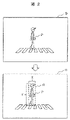
- FIG. 2 is an example of image data D obtained by photographing a pedestrian P crossing a pedestrian crossing.
- the object area cutting unit 11 detects a rectangular area including the pedestrian P as the object area R.
- the width of the object region R on the image data D is X
- the height is Y.
- the feature amount calculation unit 12 calculates the feature amount of the object area R obtained by the object area cutting unit 11.
- the feature amount calculated here is a feature amount that can quantify the movement of the limbs of the pedestrian P.
- the aspect ratio RX / Y of the object region R that fluctuates with the walking of the pedestrian P, or the object region.
- the angle of the diagonal line of R and the like will be described.
- the aspect ratio R X / Y which is an example of the feature amount, is a value obtained by dividing the width X of the object region R set in FIG. 2 by the height Y.
- the aspect ratio R X / Y can be obtained as a normalized feature amount that is not affected by the distance or unit from the stereo camera 2. ..
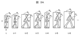
- FIG. 3A is an example of a time change of the object region R including the pedestrian P in FIG.
- the pedestrian P and the object area R from time t to time t + 6 are indicated by P 0 to P 6 and R 0 to R 6 , respectively.
- the height Y of the object region R increases as the own vehicle approaches the pedestrian P.
- the width X of the object region R becomes larger as the own vehicle approaches the pedestrian P, and at the same time, it changes depending on the walking behavior of the pedestrian P moving his / her limbs back and forth.
- the width X at time t and time t + 4 is narrower than the frames before and after
- the width X at time t + 2 and time t + 6 is wider than the frames before and after.
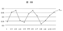
- the feature amount calculation unit 12 calculates the aspect ratio RX / Y for the object region R of the pedestrian P shown in FIG. 3A, the periodic fluctuation as shown in FIG. 3B is detected.
- the periodic fluctuation detection unit 13 monitors the feature amount of the object region R calculated by the feature amount calculation unit 12 (for example, the aspect ratio RX / Y of the object region R) in time series, and determines the presence or absence of the periodic fluctuation.
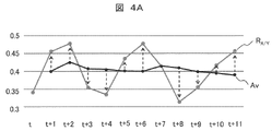
- FIG. 4A is a graph in which the value of the aspect ratio R X / Y of FIG. 3B and the value of the moving average Av, which is the average value of the aspect ratio R X / Y of the past number frames, are plotted. From this graph, it can be seen that when the aspect ratio R X / Y increases or decreases periodically, the aspect ratio R X / Y periodically increases or decreases with respect to the moving average Av.
- the periodic fluctuation detection unit 13 changes the aspect ratio R X / Y with respect to the moving average Av from the aspect ratio R X / Y obtained at each time.
- the magnitude is calculated as a "periodic fluctuation determination index", and the continuous state of the periodic fluctuation determination index is counted by the "periodic fluctuation determination index continuous counter (+ counter and-counter)".
- the periodic fluctuation detection unit 13 obtains the value of the moving average Av from the value of the aspect ratio R X / Y of the object region R of the past number frame. Further, it is determined whether the aspect ratio RX / Y at that time is larger (hereinafter referred to as “+”) or smaller (hereinafter referred to as “ ⁇ ”) than the moving average Av. Furthermore, the number of consecutive positive and negative states with respect to the moving average is obtained. Then, when the + number of consecutive times and the-number of consecutive times are substantially the same, the periodic fluctuation detection unit 13 assumes that the aspect ratio RX / Y changes periodically.
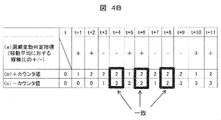
- FIG. 4B is an example of the analysis result of the graph of FIG. 4A by the periodic fluctuation detection unit 13.
- the row of FIG. 4B (a) shows the +/- state of the aspect ratio RX / Y with respect to the moving average Av of each time, which is the periodic fluctuation determination index of this determination method, and the row of FIG. 4B (b).
- the periodic fluctuation determination index of time t + 1 and time t + 2 is +
- the periodic fluctuation determination index of time t + 3 and time t + 4 is ⁇
- the periodic fluctuation determination index of time t + 5 and time t + 6 is +. Therefore, the + counter value in FIG. 4B (b) is counted up once and twice at the times t + 1 and t + 2 in which the + of the periodic fluctuation determination index is continuous, and then the time when the periodic fluctuation determination index becomes ⁇ .
- the current counter value of 2 times is held, and the count-up is restarted from 1 time at the time t + 5 when the periodic fluctuation determination index changes to + again.
- the-counter value is counted up once and twice at times t + 3 and t + 4 in which the periodic fluctuation determination index is continuous, and then at times t + 5 and t + 6 when the periodic fluctuation determination index becomes +. Holds the current counter value of 2 times.
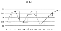
- the second periodic fluctuation determination method by the periodic fluctuation detection unit 13 will be described with reference to FIGS. 5A and 5B.
- the magnitude of the aspect ratio R X / Y with respect to the moving average Av is used as the periodic fluctuation determination index, but in FIG. 5B, the aspect ratio R X / Y of the current frame with respect to the aspect ratio R X / Y one frame before is used.
- Increase / decrease is used as a periodic fluctuation judgment index. Since the increase / decrease in the aspect ratio R X / Y before the current frame with respect to the aspect ratio R X / Y one frame before is shown by the broken line arrow in FIG.
- the periodic fluctuation detection unit 13 displays the graph in FIG. 5A.
- the analysis is performed as shown in FIG. 5B.
- the number of consecutive + and the number of consecutive ⁇ are both 2 times, which coincides with each other. It can be determined that the number has increased or decreased.
- the pedestrian determination unit 14 determines that the moving object in the object region R is the pedestrian P.
- the CAN interface IF 2 transmits the determination result to the vehicle control device 3 via the in-vehicle network CAN.
- the vehicle control device 3 executes vehicle control on the premise that the own vehicle is close to the pedestrian P.
- step S1 the camera interface IF 1 acquires image data D from the stereo camera 2.
- step S2 the object area cutting unit 11 cuts out the object area R from the image data D as shown in FIG.
- step S3 the object area cutting unit 11 collates the object area R cut out in step S2 with the object area R cut out at the previous time.
- FIGS. 2 and 3A for the sake of simplicity, a situation in which only one moving object exists in the image data D is illustrated, but in reality, there is a possibility that a plurality of moving objects exist in the image data D. Therefore, it is necessary to identify the object region R of the same object, detect the periodic fluctuation of the feature amount of the same object, and perform the pedestrian determination. Therefore, when the object area cutting unit 11 cuts out the object area R, a process of collating which area of the plurality of areas cut out at the previous time is the same object is performed.
- the actual distance to the object is due to the fact that the areas overlap on the screen, the area difference is less than a certain threshold value, and the stereo camera 2 is used. If it can be obtained, the difference between the actual distance values is equal to or less than a certain threshold value, and the like, the collation with the object cut out at the previous time is performed. Thereby, for each object region R, it is possible to determine whether or not there is a change due to reference to the past history. Here, it is assumed that n moving objects are detected.
- step S4 the feature amount calculation unit 12 sets the reference counter i of the object area R to 1.
- step S5 the feature amount calculation unit 12 determines whether or not the type flag of the object area R of the reference counter i is set.
- the type flag is a variable assigned to the object area R, and is set as "unidentified” when the object area R is detected for the first time. If the object type flag of the reference counter i is "unidentified” in step S5, the identification determination is required, so the process proceeds to step S6. If it is "pedestrian” instead of "unidentified”, it is determined that there is already a pedestrian in the object area R of the reference counter i. The process proceeds to step S12 for incrementing the count of the counter i.
- step S6 the feature amount calculation unit 12 calculates the feature amount of the object area R of the reference counter i.
- the aspect ratio R X / Y is calculated with respect to the time-series object region R.
- step S7 the periodic fluctuation detection unit 13 calculates the periodic fluctuation determination index of the object region R of the reference counter i.
- the periodic fluctuation determination index is +/- of the aspect ratio RX / Y with respect to the moving average Av shown in FIG. 4B.
- the periodic fluctuation detection unit 13 calculates ⁇ as a periodic fluctuation determination index of the object region R.
- step S8 the periodic fluctuation detection unit 13 determines whether or not the periodic fluctuation determination index of the object region R of the reference counter i has changed from the previous time. For example, in FIG. 4B, +, which was the periodic fluctuation determination index at time t + 2, has changed to ⁇ at time t + 3, so the process proceeds to step S9.
- the step S8 is a process of determining the timing at which the sign of the periodic fluctuation determination index of the object region R of the reference counter i is changed.
- step S12 the counter is incremented to the object area R of the next reference counter i because it is not the determination timing.
- step S9 the continuous counters of the object area R of the reference counter i are compared. Specifically, the + counter value and the-counter value are compared, and if they are almost the same, it is considered that there is a periodic fluctuation and the process proceeds to step S10. For example, at time t + 3 in FIG. 4B, since the + counter value is “2” and the ⁇ counter value is “1”, the process proceeds to step S11 in which the + counter value or the ⁇ counter value is incremented as if they do not match. On the other hand, at time t + 4, the + counter value is "2" and the-counter value is also "2". Therefore, it is determined that the aspect ratio RX / Y has changed periodically, and the process proceeds to step S1. ..
- step S10 since periodic fluctuations were observed in the aspect ratio RX / Y in the previous step S9, the pedestrian determination unit 14 sets the type flag of the object area R of the reference counter i to “pedestrian”.
- step S11 since the periodic fluctuation determination index of the object region R of the reference counter i does not change, or the + counter and the-counter do not match, the periodic fluctuation cannot be determined yet, so that the determination after the next time is performed. Therefore, the current states of the + counter and the-counter are updated, and the process proceeds to step S12. For example, in the case of time t + 2 in FIG. 4B, since the periodic fluctuation determination index of the current time is "+" following the previous time, the + counter is incremented by 1 as shown in 5a, and the change is changed for-. Since there is no-counter is set to 0 as it is.
- step S12 since the processing for the object area R of the reference counter i is completed, the reference counter i is incremented by 1 in order to set the next object area R as the determination target.
- step S13 it is determined whether or not the reference counter i exceeds the number of objects n set in step S3. If it does not exceed, the unprocessed object area R remains, so the process returns to step S5, and the process for the next object area R is executed. If it exceeds, the processing of the current time is terminated.
- the + counter and the-counter are judged to match when each is twice or more.
- the match judgment between the + counter and the-counter is not an exact match, and an error of about 50% is allowed. For example, it is assumed that + matches twice in a row and-matches three times in a row.
- the aspect ratio RX / Y is used as a normalized feature amount.
- the walking behavior of the pedestrian P can be accurately detected.
- the value of the diagonal angle of the object region R is used as the feature amount, the walking behavior of the pedestrian P is accurately performed based on the normalized index, as in the case of using the aspect ratio RX / Y. The effect of being able to detect is obtained.
- the normalized feature amount is used to accurately identify that the moving object in front is a pedestrian. It becomes possible.
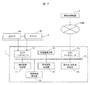
- FIG. 7 is a functional block diagram showing the configuration of the object identification device 1 of the second embodiment.
- the object identification device 1 of FIG. 7 has a configuration in which an object actual height calculation unit 15 is added to the object identification device 1 of FIG. 1 and the pedestrian determination unit 14 is replaced with a pedestrian / bicycle determination unit 14a.
- an object actual height calculation unit 15 is added to the object identification device 1 of FIG. 1 and the pedestrian determination unit 14 is replaced with a pedestrian / bicycle determination unit 14a.
- an object actual height calculation unit 15 is provided in order to obtain the height of the moving object on the actual coordinates.
- the object actual height calculation unit 15 calculates the actual height of the object region R from a stereo image from a stereo camera, for example, and uses the output of a laser radar, a millimeter wave radar, or the like to calculate the actual height of the object region R.
- the actual height may be calculated.
- an example of obtaining the actual height of the object region R using a stereo image from the stereo camera 2 will be described.
- the object actual height calculation unit 15 calculates the height in actual coordinates with respect to the object area R cut out by the object area cutting unit 11. Using a stereo image, if the number of pixels of the height Y of the object region R whose distance from the stereo camera 2 is known is known, the actual height of the object region R can be obtained by Equation 1.
- Actual height (mm) (pixel pitch x distance (mm) x height (pixel)) / focal length (mm) ... Equation 1
- the periodic fluctuation detection unit 13 calculates the periodic fluctuation determination index in the same manner as in the first embodiment, and updates the + counter and the-counter.
- the history of the actual height acquired by the object actual height calculation unit 15 is acquired, and the average value and the standard deviation in the time series direction of the same object region are calculated.
- the pedestrian / bicycle determination unit 14a determines whether or not the periodic fluctuation is detected by the matching determination between the + counter and the-counter, as in the pedestrian determination unit 14 of the first embodiment. Then, when the periodic fluctuation is detected, the standard deviation of the actual height is further referred to, and if the standard deviation is equal to or less than the threshold value, the object region R cut out by the object region cutting portion 11 is determined to be a pedestrian. , If it is larger than the threshold value, it is judged as a bicycle.
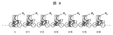
- FIG. 8 is a diagram showing the running behavior of a bicycle crossing the front of the own vehicle.
- the actual height of the object region R has already been calculated.
- the position of the lower end of the object region R fluctuates up and down due to the up and down of the position of the foot riding the bicycle, and as a result, the height of the object region R periodically changes. fluctuate. That is, since the standard deviation of the height of the object region R on the actual coordinates obtained by the periodic fluctuation detection unit 13 becomes large, it can be determined that the fluctuation of the aspect ratio R X / Y is caused by the fluctuation in the height direction.
- This is a feature seen when analyzing an image of a bicycle, and when such a feature is found, the pedestrian / bicycle determination unit 14a determines that the moving object in the object region R is a bicycle. Can be done.
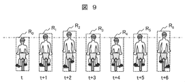
- FIG. 9 is a diagram showing the running behavior of the standing bicycle B.
- the position of the human head moves up and down periodically with the cycle of riding the bicycle, so that the standard deviation of the height on the actual coordinates becomes large as in FIG. Therefore, even when the image data D as shown in FIG. 9 is captured, the pedestrian / bicycle determination unit 14a can determine that the moving object in the object region R is a bicycle.
- Example 1 an example of detecting the walking behavior of a pedestrian by detecting the periodic fluctuation of the aspect ratio R X / Y of the object region R on the image data D has been described. This has the effect that when the object is a pedestrian, the width variation normalized by the height can be detected because the height is invariant.
- pedestrians and bicycles can be distinguished by further considering the periodic fluctuation of the actual height of the object region R on the actual coordinates. That is, if the height fluctuation on the actual coordinates is smaller than the threshold value, it is determined to be a periodic fluctuation due to the width fluctuation of the pedestrian, and if it is larger than the threshold value, it is determined to be the periodic fluctuation due to the height fluctuation of the bicycle.
- the normalized feature amount is used to accurately identify whether the moving object in front is a pedestrian or a bicycle. It becomes possible to do.
Landscapes
- Engineering & Computer Science (AREA)
- Physics & Mathematics (AREA)
- General Physics & Mathematics (AREA)
- Multimedia (AREA)
- Theoretical Computer Science (AREA)
- Computer Vision & Pattern Recognition (AREA)
- Human Computer Interaction (AREA)
- Image Analysis (AREA)
- Traffic Control Systems (AREA)
Abstract
自車速度や相対距離にかかわらず、人間の歩行特徴を抽出し、歩行者を識別する物体識別装置を提供する。カメラが撮影した画像データに基づいて移動物体の種別を識別する物体識別装置であって、前記画像データから移動物体の存在する物体領域を切り出す物体領域切出部と、前記物体領域の特徴量を算出する特徴量算出部と、前記特徴量の周期変動を検出する周期変動検出部と、検出した周期変動に基づき歩行者を判定する移動物体判定部と、を備えた物体識別装置。
Description
本発明は、カメラの撮影画像から物体の種別を識別する物体識別装置、および、物体識別方法に関する。
近年の自動車には、運転支援や自動運転の実現のため、自車両前方の移動物体の種別を識別する機能の搭載が求められている。例えば、前方の移動物体との衝突を回避する運転支援の実現には、移動物体の種別を識別したうえで、その移動物体の一般的な移動速度を考慮したブレ-キ制御をおこなう必要がある。
ここで、カメラの撮影画像に写った移動物体の種別を識別する手法として、特定物体の大量の画像を学習させて作成した識別器を用いる方法が一般に用いられる。しかし、この識別手法では、画像上の見かけの特徴パタンを学習するため、歩行者と自転車のように、撮影画像中での形状が類似した移動物体同士を正確に識別するのは困難であった。
そのため、特許文献1では、人間と推定される領域の面積の標準偏差を用いて歩行者を識別する方式が提案されている。例えば、特許文献1の請求項1では、「車両の前方を撮像する撮像手段により得られた画像より歩行者を検知する車両用の歩行者検知装置において、前記画像から人間と推定される領域を切り出し、該切り出した人間推定領域の面積を特徴量として算出する特徴量算出手段と、前記特徴量の時系列デ-タからそのばらつきを示す統計量を算出し、該算出した統計量が判定閾値より大きいとき、前記人間推定領域に対応する像が、当該車両の進行方向に対してほぼ垂直の方向に歩行している歩行者であると判定する歩行者判定手段とを備え、該歩行者判定手段は、前記特徴量の変動量の移動平均値を算出し、所定サンプル数の移動平均値の分散または標準偏差を、前記ばらつきを示す統計量として算出することを特徴とする歩行者検知装置」が開示されている。
特許文献1の歩行者検知装置によれば、画像から算出した人間の領域の面積を、時系列に平均をとり、移動平均の標準偏差が大きい場合に歩行者と判定する方式が開示されている。しかし、画面上の歩行者の面積は、歩行者自身の歩行挙動で時系列に変動する以外に、カメラを搭載した車両が歩行者に接近することによっても変動する。
このような、車両走行による移動物体までの距離変化の影響を軽減するには、車速により動的に変動するしきい値を設定しておき、車速センサから現在の速度を取得して、しきい値を設定したうえで移動物体の種別を判定する必要があった。しかしながら、正確なしきい値を設定するには、高精度の車速センサを利用する必要があるが、車両に搭載される一般的な車速センサでは低速時の検出精度が低いため、低速時には適切なしきい値を設定できず、結果的に、低速時には正確な歩行者判定を実行できないという問題があった。
そこで、本発明では、自車両が低速走行中であっても、前方の移動物体の種別を正確に判定することができる、物体識別装置、および、物体識別方法を提供することを目的とする。
上記課題を解決するための本発明の物体識別装置は、カメラが撮影した画像データに基づいて移動物体の種別を識別するものであって、前記画像データから移動物体の存在する物体領域を切り出す物体領域切出部と、前記物体領域の特徴量を算出する特徴量算出部と、前記特徴量の周期変動を検出する周期変動検出部と、検出した周期変動に基づき歩行者を判定する移動物体判定部と、を備えたものとした。
本発明の物体識別装置および物体識別方法によれば、自車両が低速走行中であっても、前方の移動物体の種別を正確に識別することが可能となる。
以下、図面等を用いて、本発明の物体検出装置の実施例について説明する。なお、以下の説明は本発明の内容の具体例を示すものであり、本発明がこれらの説明に限定されるものではなく、本明細書に開示される技術的思想の範囲内において当業者による様々な変更および修正が可能である。また、本発明を説明するための全図において、同一の機能を有するものは、同一の符号を付け、その繰り返しの説明は省略する場合がある。
まず、図1から図6を用いて、本発明の実施例1に係る物体識別装置1を説明する。
図1は、自車両に搭載された、実施例1の物体識別装置1、ステレオカメラ2、車両制御装置3の概略構成を示す機能ブロック図である。
ステレオカメラ2は、左カメラ2Lと右カメラ2Rの撮像素子を用いて、自車両前方のステレオ画像を撮影し、画像データDとして出力する外界センサである。なお、本発明で用いる外界センサは、画像データD内の各物体との距離を検出可能なセンサであれば良く、単眼カメラに、レーザレーダ、ミリ波レーダ、超音波センサ等の測距センサを組み合わせた外界センサであっても良い。
物体識別装置1は、ステレオカメラ2が撮影したステレオ画像(画像データD)に基づいて自車両周辺の移動物体の種別を識別し、その識別結果を車載ネットワ-クCANを介して車両制御装置3に出力する装置である。なお、物体識別装置1が識別する移動物体の種別は、他車両、バイク、自転車、歩行者等であるが、本実施例では歩行者の識別方法を説明し、実施例2では歩行者と自転車の識別方法を説明する。
車両制御装置3は、自車両の加速系、制動系、操舵系等を制御するECU(Electronic Control Unit)であり、物体識別装置1による移動物体の識別結果を踏まえて、移動物体との衝突等を回避できるように自車両の制動や操舵等を適切に制御する。なお、識別結果に応じた自車両制御には周知技術を利用できるので、以下では車両制御装置3の詳細説明を省略する。
<物体識別装置1の詳細構造>
図1に示すように、物体識別装置1は、内部バス10、物体領域切出部11、特徴量算出部12、周期変動検出部13、歩行者判定部14、カメラインタフェースIF1、CANインタフェースIF2を備えている。なお、物体識別装置1は、具体的には、マイコン等の演算装置、半導体メモリ等の記憶装置、および、通信装置などのハ-ドウェアを備えたコンピュータである。そして、記憶装置にロードされたプログラムを演算装置が実行することで、物体領域切出部11等の各機能を実現するが、以下では、このような周知技術を適宜省略しながら、各部の詳細を順次説明する。
図1に示すように、物体識別装置1は、内部バス10、物体領域切出部11、特徴量算出部12、周期変動検出部13、歩行者判定部14、カメラインタフェースIF1、CANインタフェースIF2を備えている。なお、物体識別装置1は、具体的には、マイコン等の演算装置、半導体メモリ等の記憶装置、および、通信装置などのハ-ドウェアを備えたコンピュータである。そして、記憶装置にロードされたプログラムを演算装置が実行することで、物体領域切出部11等の各機能を実現するが、以下では、このような周知技術を適宜省略しながら、各部の詳細を順次説明する。
カメラインタフェースIF1は、ステレオカメラ2からステレオ画像(画像データD)を取得する。取得した画像データDは、内部バス10を通して図示しない記憶部に記憶される。
物体領域切出部11は、記憶部に記憶された画像データDから、物体領域Rを切り出す。これは画像データDから同一物体の映った領域を抽出する処理であり、様々な方法を用いることができる。たとえばステレオ画像では、画像間の視差により画像データD上の各点の距離を算出できるので、画像データD上で近接しており、かつ、自車両との相対距離が類似する画像領域をグル-ピングすることで物体領域Rを抽出することができる。
図2は、横断歩道を横断中の歩行者Pを撮影した画像データDの一例である。この画像データDを処理対象とする場合、物体領域切出部11は、歩行者Pを含む矩形の領域を物体領域Rとして検出する。なお、以下では、画像データD上での物体領域Rの幅をX、高さをYとする。
特徴量算出部12は、物体領域切出部11で求めた物体領域Rの特徴量を算出する。ここで算出する特徴量は、歩行者Pの手足の動きを定量化できる特徴量であり、例えば、歩行者Pの歩行に伴い変動する物体領域Rの縦横比RX/Y、もしくは、物体領域Rの対角線の角度などである。以降では、物体領域Rの縦横比RX/Yを特徴量とした場合について説明する。
特徴量の一例である縦横比RX/Yは、図2で設定した物体領域Rの幅Xを高さYで割った値である。自車両が歩行者Pに近づくと、仮に歩行者Pの姿勢が同一であっても、画像データD上での物体領域Rは徐々に拡大するが、実際の歩行者Pは高さ(身長)は変わらないため、物体領域Rの幅Xを高さYで割ることで、ステレオカメラ2からの距離や単位に影響されない正規化された特徴量として、縦横比RX/Yを求めることができる。
図3Aは、図2の歩行者Pを含む物体領域Rの時間変化の一例である。ここでは、時刻t~時刻t+6の歩行者Pと物体領域Rを、それぞれ、P0~P6、R0~R6で示している。この図から明らかなように、物体領域Rの高さYは、自車両が歩行者Pに近づくほど大きくなる。また、物体領域Rの幅Xは、自車両が歩行者Pに近づくほど大きくなると同時に、歩行者Pが手足を前後に動かす歩行挙動によっても変化する。例えば、時刻tや時刻t+4での幅Xは前後のフレームより狭まっており、時刻t+2や時刻t+6での幅Xは前後のフレームより広がっている。
このため、特徴量算出部12が、図3Aに示す歩行者Pの物体領域Rを対象として縦横比RX/Yを算出すると、図3Bに示すような周期変動が検出される。
周期変動検出部13は、特徴量算出部12で算出した物体領域Rの特徴量(例えば、物体領域Rの縦横比RX/Y)を時系列で監視し、周期変動の有無を判断する。
(第一の周期変動判定方法)
ここで、図4Aと図4Bを用いて、周期変動検出部13による、第一の周期変動判定方法を説明する。図4Aは、図3Bの縦横比RX/Yの値と、過去数フレ-ムの縦横比RX/Yの平均値である移動平均Avの値をプロットしたグラフである。このグラフからは、縦横比RX/Yが周期的に増減すると、移動平均Avに対して縦横比RX/Yが周期的に上下することが分かる。
ここで、図4Aと図4Bを用いて、周期変動検出部13による、第一の周期変動判定方法を説明する。図4Aは、図3Bの縦横比RX/Yの値と、過去数フレ-ムの縦横比RX/Yの平均値である移動平均Avの値をプロットしたグラフである。このグラフからは、縦横比RX/Yが周期的に増減すると、移動平均Avに対して縦横比RX/Yが周期的に上下することが分かる。
そこで、周期変動検出部13は、縦横比RX/Yの周期的な増減を検出するために、時刻ごとに得られる縦横比RX/Yから、移動平均Avに対する縦横比RX/Yの大小を「周期変動判定指標」として算出し、周期変動判定指標の連続状態を「周期変動判定指標連続カウンタ(+カウンタ、および、-カウンタ)」でカウントする。
まず、周期変動検出部13は、過去数フレ-ムの物体領域Rの縦横比RX/Yの値から、移動平均Avの値を求める。また、その時刻の縦横比RX/Yが移動平均Avより大きい(以下「+」と表記する)か小さい(以下「-」と表記する)かを求める。さらに、移動平均に対する+の状態、-の状態の連続する回数を求める。そして、+連続回数と-連続回数がほぼ一致する場合に、周期変動検出部13は、縦横比RX/Yが周期的に変動したとする。
図4Bは、周期変動検出部13による図4Aのグラフの解析結果の一例である。図4B(a)の行に、本判定方法の周期変動判定指標である、それぞれの時刻の移動平均Avに対する縦横比RX/Yの+/-の状態を示し、図4B(b)の行に+の連続回数である+カウンタ値を、図4B(c)の行に-の連続回数である-カウンタ値を示している。
この例では、時刻t+1と時刻t+2の周期変動判定指標が+、時刻t+3と時刻t+4の周期変動判定指標が-、時刻t+5と時刻t+6の周期変動判定指標が+である。そのため、図4B(b)の+カウンタ値は、周期変動判定指標の+が連続する時刻t+1、t+2では1回、2回とカウントアップしていき、その後、周期変動判定指標が-となる時刻t+3、t+4では、現状のカウンタ値である2回を保持し、周期変動判定指標が再度+に変動した時刻t+5の時点で、1回からカウントアップを再開する。同様に、-カウンタ値は、周期変動判定指標の-が連続する時刻t+3、t+4では1回、2回とカウントアップしていき、その後、周期変動判定指標が+となる時刻t+5、t+6では、現状のカウンタ値である2回を保持する。
このように、+カウンタ値と-カウンタ値をカウントアップさせると、時刻t+4の時点で、+の連続回数と-の連続回数が共に2回となり一致することを検知でき、周期変動検出部13は、一定周期で縦横比RX/Yが増減したと判定することができる。
(第二の周期変動判断方法)
次に、図5Aと図5Bを用いて、周期変動検出部13による、第二の周期変動判定方法を説明する。図4Bでは、移動平均Avに対する縦横比RX/Yの大小を周期変動判定指標としたが、図5Bでは、1フレーム前の縦横比RX/Yに対する現フレームの縦横比RX/Yの増減を周期変動判定指標とする。1フレーム前の縦横比RX/Yに対する現フレーム前の縦横比RX/Yの増減は、図5Aの破線矢印のように示されるため、周期変動検出部13は、図5Aのグラフを、図5Bのように解析する。図5Bでも図4Bと同様に、時刻t+4の時点で、+の連続回数と-の連続回数が共に2回となり一致するため、周期変動検出部13は、一定周期で縦横比RX/Yが増減したと判定することができる。
次に、図5Aと図5Bを用いて、周期変動検出部13による、第二の周期変動判定方法を説明する。図4Bでは、移動平均Avに対する縦横比RX/Yの大小を周期変動判定指標としたが、図5Bでは、1フレーム前の縦横比RX/Yに対する現フレームの縦横比RX/Yの増減を周期変動判定指標とする。1フレーム前の縦横比RX/Yに対する現フレーム前の縦横比RX/Yの増減は、図5Aの破線矢印のように示されるため、周期変動検出部13は、図5Aのグラフを、図5Bのように解析する。図5Bでも図4Bと同様に、時刻t+4の時点で、+の連続回数と-の連続回数が共に2回となり一致するため、周期変動検出部13は、一定周期で縦横比RX/Yが増減したと判定することができる。
歩行者判定部14は、周期変動検出部13で周期的な変動を検出した場合に、その物体領域R内の移動物体を歩行者Pと判定する。
CANインタフェースIF2は、歩行者判定部14が歩行者Pを検出した場合に、その判定結果を、車載ネットワ-クCANを介して、車両制御装置3に送信する。その結果、車両制御装置3は、自車両が歩行者Pに接近しているという前提での車両制御を実行する。
<物体識別装置1による処理のフローチャート>
以上で説明した本実施例の物体識別装置1の処理の流れを、図6のフローチャートを用いて説明する。
以上で説明した本実施例の物体識別装置1の処理の流れを、図6のフローチャートを用いて説明する。
ステップS1では、カメラインタフェースIF1は、ステレオカメラ2から画像データDを取得する。
ステップS2では、物体領域切出部11は、図2に示すように、画像データDから物体領域Rを切り出す。
ステップS3では、物体領域切出部11は、ステップS2で切り出した物体領域Rを、前時刻に切り出した物体領域Rと照合する。図2や図3Aでは、簡単のため画像データD内に移動物体が一つだけ存在する状況を例示したが、実際には、画像データD中には複数の移動物体が存在する可能性があるため、同一物体の物体領域Rを識別したうえで、同一物体の特徴量の周期変動を検出し歩行者判定を実施する必要がある。そのため、物体領域切出部11が物体領域Rを切り出す際に、前の時刻で切り出した複数の領域のどの領域と同じ物体であるかを照合する処理を実施する。連続した時刻間での物体の照合は、画面上で領域が重なっている、面積の差分が一定しきい値以下である、また、ステレオカメラ2を用いているなどで物体との実際の距離が取得できる場合には、実際の距離の値の差分が一定しきい値以下である、等の条件判定により、前の時刻で切り出した物体との照合をとっておく。これにより、それぞれの物体領域Rについて、過去の履歴の参照による変動の有無を判定することができる。なお、ここでは、n個の移動物体が検出されたものする。
ステップS4では、特徴量算出部12は、物体領域Rの参照カウンタiを1に設定する。
ステップS5では、特徴量算出部12は、参照カウンタiの物体領域Rの種別フラグが設定されているか否かを判定する。種別フラグは物体領域Rに割り当てられた変数であり、物体領域Rが初めて検出されたときに「未識別」と設定される。ステップS5で参照カウンタiの物体の種別フラグが「未識別」である場合は、識別判定が必要であるのでステップS6に進む。「未識別」でなく「歩行者」となっている場合は、参照カウンタiの物体領域Rに既に歩行者がいると判定されているので、他の物体領域Rを判定対象とすべく、参照カウンタiのカウントをインクリメントするステップS12の処理に進む。
ステップS6では、特徴量算出部12は、参照カウンタiの物体領域Rの特徴量を算出する。例えば、図3A、図3Bのように、時系列の物体領域Rに対して縦横比RX/Yを算出する。
ステップS7では、周期変動検出部13は、参照カウンタiの物体領域Rの周期変動判定指標を算出する。以降、周期変動判定指標が、図4Bに示す、移動平均Avに対する縦横比RX/Yの+/-である場合の事例で説明する。例えば、時刻t+3では、移動平均値Avより縦横比RX/Yが小さいため、周期変動検出部13は、物体領域Rの周期変動判定指標として-を算出する。
ステップS8では、周期変動検出部13は、参照カウンタiの物体領域Rの周期変動判定指標が前時刻から変化したか否かを判定する。例えば、図4Bでは、時刻t+2の周期変動判定指標であった+が、時刻t+3では-に変化しているため、ステップS9の処理に進む。このように、ステップS8は、参照カウンタiの物体領域Rの周期変動判定指標の符号に変化がみられるタイミングを判定する処理である。一方、周期変動判定指標の符号に変化が見られない場合は、判定のタイミングでないため次の参照カウンタiの物体領域RにカウンタをインクリメントするステップS12の処理に進む。
ステップS9では、参照カウンタiの物体領域Rの連続カウンタを比較する。具体的には+カウンタ値と-カウンタ値を比較し、これがほぼ一致すれば周期変動ありとしてステップS10の処理に進む。例えば、図4Bの時刻t+3では、+カウンタ値は「2」、-カウンタ値は「1」であるため、一致せずとして+カウンタ値または-カウンタ値をインクリメントするステップS11の処理に進む。これに対し、時刻t+4では、+カウンタ値は「2」、-カウンタ値も「2」であるため、縦横比RX/Yが周期的に変動したと判定して、ステップS1の処理に進む。
ステップS10では、前のステップS9で縦横比RX/Yに周期変動が見られたため、歩行者判定部14は、参照カウンタiの物体領域Rの種別フラグを「歩行者」に設定する。
一方、ステップS11では、参照カウンタiの物体領域Rの周期変動判定指標に変化がない、もしくは+カウンタと-カウンタが一致しないことから、周期変動の判定がまだ実施できないため、次時刻以降の判定のために、現状の+カウンタと-カウンタの状態を更新してステップS12に進む。例えば、図4Bの時刻t+2の場合は、現在時刻の周期変動判定指標が前時刻に引き続いて「+」であるため、5aに示すように+カウンタを1インクリメントした2とし、-については変化がないため-カウンタをそのまま0とする。
ステップS12では、参照カウンタiの物体領域Rに対する処理が終了したため、次の物体領域Rを判定対象とすべく、参照カウンタiを1インクリメントする。
ステップS13では、参照カウンタiがステップS3で設定した物体数nを超えたか否かを判定する。超えていない場合は未処理の物体領域Rが残っているため、ステップS5に戻り、次の物体領域Rに対する処理を実行する。超えている場合は現在時刻の処理を終了する。
なお、ステップS9の+カウンタと-カウンタの一致判定については、より正確な判定のために、次に挙げる各方法を採っても良い。
(1)ノイズの値変動による誤判定を避けるため、+カウンタと-カウンタはそれぞれ2回以上の場合に一致判定する。
(2)+カウンタと-カウンタの一致判定は、完全一致でなく、50%程度の誤差は許容するとする。例えば、+が2回連続して、-が3回連続した場合も一致したとする。
(3)+の連続回数と-の連続回数が初めて一致した時点で周期変動と判定するのでなく、一致が二回以上連続した時点で判定することで、よりロバストな判定とすることができる。図4Bや図5Bの例では、時刻t+6の時点で二回目の一致が検出されるので、この時点で周期変動と判定する。
以上の構成により、自車両の移動により移動物体との距離が変化しても、同じ歩行者の高さ(身長)は一定であることに鑑み、正規化した特徴量として縦横比RX/Yを算出することで歩行者Pの歩行挙動を正確に検出することができる。また、特徴量として物体領域Rの対角線の角度の値を用いた場合も、縦横比RX/Yを利用する場合と同様に、正規化した指標に基づいて歩行者Pの歩行挙動を正確に検出できるという効果が得られる。
以上で説明した本実施例の物体識別装置によれば、自車両が低速走行中であっても、正規化した特徴量を用いて、前方の移動物体が歩行者であることを正確に識別することが可能となる。
次に、図7から図9を用いて、本発明の実施例2に係る物体識別装置1を説明する。なお、実施例1との共通点は重複説明を省略する。
図7は、実施例2の物体識別装置1の構成を示す機能ブロック図である。図7の物体識別装置1は、図1の物体識別装置1に対し、物体実高算出部15を追加するとともに、歩行者判定部14を歩行者/自転車判定部14aに置き換えた構成である。以下、実施例1と異なる構成につき説明する。
本実施例は、移動物体の実座標上の高さを求めるため、物体実高算出部15を備えた。
物体実高算出部15は、例えば、ステレオカメラからのステレオ画像から物体領域Rの実際の高さを算出するものであるが、レーザレーダ、ミリ波レーダなどの出力を用いて、物体領域Rの実際の高さを算出しても良い。以降はステレオカメラ2からのステレオ画像を用いて物体領域Rの実高さを求める例で説明する。
物体実高算出部15は、例えば、ステレオカメラからのステレオ画像から物体領域Rの実際の高さを算出するものであるが、レーザレーダ、ミリ波レーダなどの出力を用いて、物体領域Rの実際の高さを算出しても良い。以降はステレオカメラ2からのステレオ画像を用いて物体領域Rの実高さを求める例で説明する。
物体実高算出部15は、物体領域切出部11で切り出した物体領域Rに対し、実座標上の高さを算出する。ステレオ画像を用いると、ステレオカメラ2からの距離が既知の物体領域Rの高さYの画素数が分かれば、その物体領域Rの実際の高さは式1で求めることができる。
実高さ(mm)=(画素ピッチ×距離(mm)×高さ(画素))/焦点距離(mm)…式1
周期変動検出部13では、実施例1と同様に周期変動判定指標を算出し、+カウンタと-カウンタを更新する。それに加え、本実施例では、物体実高算出部15で取得した実高さの履歴を取得し、同一物体領域の時系列方向の平均値と標準偏差を算出する。
周期変動検出部13では、実施例1と同様に周期変動判定指標を算出し、+カウンタと-カウンタを更新する。それに加え、本実施例では、物体実高算出部15で取得した実高さの履歴を取得し、同一物体領域の時系列方向の平均値と標準偏差を算出する。
歩行者/自転車判定部14aでは、実施例1の歩行者判定部14と同様に、+カウンタと-カウンタの一致判定により、周期変動が検出されたかを判定する。そして、周期変動が検出された場合に、さらに実高さの標準偏差を参照し、標準偏差がしきい値以下であれば物体領域切出部11で切り出した物体領域Rを歩行者と判定し、しきい値より大きければ自転車と判定する。
歩行者/自転車判定部14aでの処理につき、図8を用いて説明する。図8は自車両の前方を横切る自転車の走行挙動を示した図である。なお、ここでは、物体領域Rの実高さは既に算出されているものとする。この場合、人の頭の高さが変化しない一方で、自転車をこぐ足の位置の上下により物体領域Rの下端の位置が上下に変動し、その結果、物体領域Rの高さが周期的に変動する。つまり、周期変動検出部13で求める実座標上での物体領域Rの高さの標準偏差が大きくなるため、縦横比RX/Yの変動が高さ方向の変動に起因すると判断できる。これは、自転車の画像を解析した時に見られる特徴であるので、このような特徴がみられた場合に、歩行者/自転車判定部14aは、物体領域R内の移動物体を自転車と判定することができる。
同様に、図9に示すのは、立ちこぎしている自転車Bの走行挙動を示した図である。凍場合は、自転車をこぐ周期に伴い人の頭の位置が周期的に上下するため、図8と同様に実座標上の高さの標準偏差が大きくなる。従って、図9のような画像データDを撮影した場合も、歩行者/自転車判定部14aは、物体領域R内の移動物体を自転車と判定することができる。
実施例1では、画像データD上での物体領域Rの縦横比RX/Yの周期変動を検出することで歩行者の歩行挙動を検出する例を記載した。これは、物体が歩行者の場合、高さが不変であることから高さで正規化した幅変動を検出できる効果があった。
一方、実施例2では、さらに、実座標上での物体領域Rの実高さの周期変動を考慮することで、歩行者と自転車を区別できるようにした。すなわち、実座標上の高さ変動がしきい値より小さければ、歩行者の幅変動による周期変動と判定し、しきい値より大きければ自転車の高さ変動による周期変動と判定する。
以上で説明した本実施例の物体識別装置1によれば、自車両が低速走行中であっても、正規化した特徴量を用いて、前方の移動物体が歩行者か自転車かを正確に識別することが可能となる。
1…物体識別装置、11…物体領域切出部、12…特徴量算出部、13…周期変動検出部、14…歩行者判定部、14a…歩行者/自転車判定部、15…物体実高算出部、IF1…カメラインタフェース、IF2…CANインタフェース、2…ステレオカメラ、2L…左カメラ、2R…右カメラ、3…車両制御装置、D…画像データ、P…歩行者、B…自転車、R…物体領域、W…物体領域の幅、H…物体領域の高さ、RX/Y…物体領域の縦横比、Av…縦横比の移動平均
Claims (8)
- カメラが撮影した画像データに基づいて移動物体の種別を識別する物体識別装置であって、
前記画像データから移動物体の存在する物体領域を切り出す物体領域切出部と、
前記物体領域の特徴量を算出する特徴量算出部と、
前記特徴量の周期変動を検出する周期変動検出部と、
検出した周期変動に基づき歩行者を判定する移動物体判定部と、
を備えたことを特徴とする物体識別装置。 - 請求項1に記載の物体識別装置において、
前記特徴量算出部は、前記物体領域の特徴量として、前記画像データでの前記物体領域の縦横比を算出することを特徴とする物体認識装置。 - 請求項1に記載の物体識別装置において、
前記特徴量算出部は、前記物体領域の特徴量として、前記画像データでの前記物体領域の対角線の角度を算出することを特徴とする物体認識装置。 - 請求項1に記載の物体識別装置において、
前記移動物体判定部は、前記特徴量の値が、前記特徴量の移動平均値を周期的に上下する場合に、前記物体領域内の移動物体を歩行者と判定することを特徴とする物体認識装置。 - 請求項1に記載の物体識別装置において、
前記移動物体判定部は、前記特徴量の値が、前記特徴量の移動平均を超える連続回数と超えない連続回数の比率がほぼ一致する場合に、前記物体領域内の移動物体を歩行者と判定することを特徴とする物体認識装置。 - 請求項1に記載の物体識別装置において、
前記移動物体判定部は、前記特徴量の値が、前記特徴量の前回値を超える連続回数と超えない連続回数の比率がほぼ一致する場合に、前記物体領域内の移動物体を歩行者と判定することを特徴とする物体認識装置。 - 請求項1に記載の物体識別装置において、
前記移動物体判定部は、前記移動物体との距離と、前記移動物体の画像データ上の高さから、前記物体領域の実座標上の高さを算出し、実座標上の高さの周期変動に基づいて、前記移動物体を自転車と判定することを特徴とする物体認識装置。 - カメラが撮影した画像データに基づいて移動物体の種別を識別する物体識別方法であって、
前記画像データから移動物体の存在する物体領域を切り出すステップと、
前記物体領域の特徴量を算出するステップと、
前記特徴量の周期変動を検出するステップと、
検出した周期変動に基づき歩行者を判定するステップと、
を備えたことを特徴とする物体識別方法。
Priority Applications (1)
| Application Number | Priority Date | Filing Date | Title |
|---|---|---|---|
| DE112021005035.4T DE112021005035T5 (de) | 2020-12-16 | 2021-09-13 | Objektidentifikationsvorrichtung und objekt-identifikationsverfahren |
Applications Claiming Priority (2)
| Application Number | Priority Date | Filing Date | Title |
|---|---|---|---|
| JP2020-208185 | 2020-12-16 | ||
| JP2020208185A JP7482767B2 (ja) | 2020-12-16 | 2020-12-16 | 物体識別装置、および、物体識別方法 |
Publications (1)
| Publication Number | Publication Date |
|---|---|
| WO2022130709A1 true WO2022130709A1 (ja) | 2022-06-23 |
Family
ID=82059434
Family Applications (1)
| Application Number | Title | Priority Date | Filing Date |
|---|---|---|---|
| PCT/JP2021/033451 Ceased WO2022130709A1 (ja) | 2020-12-16 | 2021-09-13 | 物体識別装置、および、物体識別方法 |
Country Status (3)
| Country | Link |
|---|---|
| JP (1) | JP7482767B2 (ja) |
| DE (1) | DE112021005035T5 (ja) |
| WO (1) | WO2022130709A1 (ja) |
Families Citing this family (1)
| Publication number | Priority date | Publication date | Assignee | Title |
|---|---|---|---|---|
| KR102662709B1 (ko) * | 2023-05-08 | 2024-04-30 | 이종선 | 안전운전 지원 시스템 |
Citations (2)
| Publication number | Priority date | Publication date | Assignee | Title |
|---|---|---|---|---|
| JP2009042941A (ja) * | 2007-08-07 | 2009-02-26 | Honda Motor Co Ltd | 対象物種別判定装置、車両、対象物種別判定方法、並びに対象物種別判定用プログラム |
| JP2012203657A (ja) * | 2011-03-25 | 2012-10-22 | Nikon Corp | 電子機器及び取得方法 |
Family Cites Families (1)
| Publication number | Priority date | Publication date | Assignee | Title |
|---|---|---|---|---|
| JP4267171B2 (ja) | 1999-05-10 | 2009-05-27 | 本田技研工業株式会社 | 歩行者検知装置 |
-
2020
- 2020-12-16 JP JP2020208185A patent/JP7482767B2/ja active Active
-
2021
- 2021-09-13 DE DE112021005035.4T patent/DE112021005035T5/de active Pending
- 2021-09-13 WO PCT/JP2021/033451 patent/WO2022130709A1/ja not_active Ceased
Patent Citations (2)
| Publication number | Priority date | Publication date | Assignee | Title |
|---|---|---|---|---|
| JP2009042941A (ja) * | 2007-08-07 | 2009-02-26 | Honda Motor Co Ltd | 対象物種別判定装置、車両、対象物種別判定方法、並びに対象物種別判定用プログラム |
| JP2012203657A (ja) * | 2011-03-25 | 2012-10-22 | Nikon Corp | 電子機器及び取得方法 |
Also Published As
| Publication number | Publication date |
|---|---|
| JP2022095079A (ja) | 2022-06-28 |
| DE112021005035T5 (de) | 2023-08-17 |
| JP7482767B2 (ja) | 2024-05-14 |
Similar Documents
| Publication | Publication Date | Title |
|---|---|---|
| JP5939357B2 (ja) | 移動軌跡予測装置及び移動軌跡予測方法 | |
| CN105716567B (zh) | 通过单眼图像获取设备侦测物体与机动车辆距离的方法 | |
| US8175334B2 (en) | Vehicle environment recognition apparatus and preceding-vehicle follow-up control system | |
| US20140037138A1 (en) | Moving object recognition systems, moving object recognition programs, and moving object recognition methods | |
| US9965690B2 (en) | On-vehicle control device | |
| US20130073194A1 (en) | Vehicle systems, devices, and methods for recognizing external worlds | |
| US11151395B2 (en) | Roadside object detection device, roadside object detection method, and roadside object detection system | |
| JP6722084B2 (ja) | 物体検出装置 | |
| CN110909718B (zh) | 驾驶状态识别方法、装置及车辆 | |
| EP1640937B1 (en) | Collision time estimation apparatus and method for vehicles | |
| US8160300B2 (en) | Pedestrian detecting apparatus | |
| US20180075749A1 (en) | Forward collision warning system and method | |
| CN116543047A (zh) | 多摄像机系统的位置估算自诊断方法、装置及存储介质 | |
| JP5097681B2 (ja) | 地物位置認識装置 | |
| CN114333414A (zh) | 停车让行检测装置、停车让行检测系统以及记录介质 | |
| JP2022095079A (ja) | 物体識別装置、および、物体識別方法 | |
| AU2017423460A1 (en) | Analysis apparatus, analysis method, and program | |
| CN114332786B (zh) | 数据处理方法及装置 | |
| US20240371175A1 (en) | Object Recognition Method and Object Recognition Device | |
| CN116416822A (zh) | 前车碰撞预警方法、系统、介质及设备 | |
| JP2018073049A (ja) | 画像認識装置、画像認識システム、及び画像認識方法 | |
| JP2020101935A (ja) | 画像認識装置 | |
| WO2023032255A1 (ja) | 画像処理装置 | |
| JP7283268B2 (ja) | 情報処理装置及び車載システム | |
| JP5811951B2 (ja) | 対象物変化検出装置 |
Legal Events
| Date | Code | Title | Description |
|---|---|---|---|
| 121 | Ep: the epo has been informed by wipo that ep was designated in this application |
Ref document number: 21906074 Country of ref document: EP Kind code of ref document: A1 |
|
| 122 | Ep: pct application non-entry in european phase |
Ref document number: 21906074 Country of ref document: EP Kind code of ref document: A1 |