US20140037138A1 - Moving object recognition systems, moving object recognition programs, and moving object recognition methods - Google Patents
Moving object recognition systems, moving object recognition programs, and moving object recognition methods Download PDFInfo
- Publication number
- US20140037138A1 US20140037138A1 US13/689,196 US201213689196A US2014037138A1 US 20140037138 A1 US20140037138 A1 US 20140037138A1 US 201213689196 A US201213689196 A US 201213689196A US 2014037138 A1 US2014037138 A1 US 2014037138A1
- Authority
- US
- United States
- Prior art keywords
- moving object
- risk
- camera
- feature points
- distance
- Prior art date
- Legal status (The legal status is an assumption and is not a legal conclusion. Google has not performed a legal analysis and makes no representation as to the accuracy of the status listed.)
- Granted
Links
Images
Classifications
-
- G—PHYSICS
- G08—SIGNALLING
- G08G—TRAFFIC CONTROL SYSTEMS
- G08G1/00—Traffic control systems for road vehicles
- G08G1/16—Anti-collision systems
- G08G1/166—Anti-collision systems for active traffic, e.g. moving vehicles, pedestrians, bikes
-
- G06K9/00805—
-
- G—PHYSICS
- G06—COMPUTING; CALCULATING OR COUNTING
- G06V—IMAGE OR VIDEO RECOGNITION OR UNDERSTANDING
- G06V20/00—Scenes; Scene-specific elements
- G06V20/50—Context or environment of the image
- G06V20/56—Context or environment of the image exterior to a vehicle by using sensors mounted on the vehicle
- G06V20/58—Recognition of moving objects or obstacles, e.g. vehicles or pedestrians; Recognition of traffic objects, e.g. traffic signs, traffic lights or roads
Definitions
- the present invention relates to moving object recognition systems, moving object recognition programs, and moving object recognition methods for recognizing moving objects by using single-view images.
- the distance from the vehicle to a moving object can be directly measured by using a distance sensor such as a millimeter-wave radar, or can be measured by performing image processing with a stereo camera.
- the moving direction of the moving object and the velocity of the moving object relative to the vehicle can be determined by arranging measured distances in chronological order and then analyzing those distances. As the moving direction of the moving object and the velocity of the moving object relative to the vehicle are determined, the probability (risk) of the moving object colliding with the vehicle can be calculated, and reporting can be performed in accordance with the risk.
- feature points are extracted from each of single-view images arranged in chronological order, and the feature points are grouped by moving objects, based on the motion vectors (optical flows) of the extracted feature points.
- the grouping is performed based on variations in the convergence properties of the optical flows to a vanishing point and the external ratios. In this manner, accurate moving object detection can be performed, even if there is an inaccurately-calculated optical flow.
- the reliability of a result of recognition processing does not always match an actual risk of collision. That is, the risk of collision might be zero, though the result of recognition processing shows a high level of reliability, and vice versa.
- Information that is useful to most drivers is not the information about the reliability of recognition processing but the information about the risk of a recognized moving object colliding with his/her own vehicle.
- the present invention has been made in view of the above problems, and the object thereof is to provide a moving object recognition system that senses a danger of collision of a moving object by using a monocular camera, instead of a relatively expensive sensor such as a stereo camera or a distance sensor.
- a moving object recognition system includes: a camera configured to capture a plurality of continuous single-view images, the camera being installed in a vehicle; a moving object detecting unit configured to detect a moving object from the images captured by the camera; a relative approach angle estimating unit configured to estimate a relative approach angle of the moving object detected by the moving object detecting unit with respect to the camera; and a collision risk calculating unit configured to calculate a risk of the moving object colliding with the vehicle, based on a relationship between the relative approach angle and a moving object direction from the camera toward the moving object.
- the risk of a moving object colliding with the vehicle can be obtained as information useful for the driver of the vehicle to drive safely.
- the risk calculation is performed with a relatively inexpensive mechanism such as a monocular camera, instead of a relatively expensive mechanism such as a stereo camera. Accordingly, the costs can be lowered.
- the collision risk calculating unit may make the risk higher as the difference between the relative approach angle and the moving object direction becomes smaller.
- the moving object When the relative approach angle matches the moving object direction, the moving object is heading toward the vehicle in a relative manner. In view of this, the risk becomes higher, as the difference between the relative approach angle and the moving object direction becomes smaller. Accordingly, the risk of a moving object colliding with the vehicle can be accurately calculated by the above structure.
- the collision risk calculating unit may set a danger zone based on the relative approach angle, and calculate the risk based on a probability of the moving object existing in the danger zone.
- the risk of a moving object colliding with the vehicle can be accurately calculated by using not only the relative approach angle of the moving object with respect to the vehicle, but also the danger zone that is set based on the relative approach angle.
- the danger zone may be set in an X-Z plane where the camera is the point of origin, an optical axis direction of the camera is a Z direction, a vertical direction is a Y direction, and a horizontal direction is an X direction, and may be a region extending from the vehicle in a direction at the relative approach angle and having a width of the vehicle.
- the danger zone is designed to have a width equivalent to the width of the vehicle and extend from the vehicle in the direction at the relative approach angle. Accordingly, the risk of collision with any portion of the vehicle can be calculated.
- the collision risk calculating unit may include: a distance estimating unit configured to estimate an upper limit value of a distance from the camera to the moving object in the Z direction; and a risk calculating unit configured to calculate the risk by determining a proportion of a line segment existing in the danger zone to a line segment of an XZ ray between the camera and the upper limit value, the XZ ray being a line segment formed by orthographically projecting a straight line onto the X-Z plane, the straight line passing through the camera and the moving object in the images located at a focal distance from the camera.
- an upper limit is set on the danger zone. Accordingly, even if the distance to a moving object cannot be determined, the probability of the moving object existing in the danger zone can be calculated by identifying the moving object direction.
- the moving object detecting unit may include: an optical flow calculating unit configured to extract a plurality of feature points from the images, and calculate optical flows of the extracted feature points; and a grouping unit configured to group, among the extracted feature points, a plurality of feature points having the optical flows extended therefrom and converging at a vanishing point as a plurality of feature points existing on the moving object, and the distance estimating unit may select a lowest feature point having the lowest height among the grouped feature points existing on the moving object, and estimate the upper limit value of the distance from the camera to the moving object in the Z direction by calculating a Z-coordinate of a ground surface point that is an intersection point between a straight line connecting the lowest feature point to the optical center and a ground surface on which the vehicle is running.
- the collision risk calculating unit may include: a distance estimating unit configured to estimate a distance from the camera to the moving object in the Z direction; and a risk calculating unit configured to make the risk higher when a point at the estimated distance from the camera on an XZ ray exists in the danger zone than when the point does not exist in the danger zone, the XZ ray being a line segment formed by orthographically projecting a straight line onto the X-Z plane, the straight line passing through the camera and the moving object in the images located at a focal distance from the camera.
- the distance to a moving object is estimated. Accordingly, it is possible to determine whether the moving object exists in the danger zone, instead of the probability of the moving object existing in the danger zone. If the moving object is determined to be in the danger zone, the risk is calculated to be high. The risk may be divided into a few levels in accordance with portions of the vehicle with which the moving object collides.
- the moving object detecting unit may include: an optical flow calculating unit configured to extract a plurality of feature points from the images, and calculate optical flows of the extracted feature points; and a grouping unit configured to group, among the extracted feature points, a plurality of feature points having the optical flows extended therefrom and converging at a vanishing point as a plurality of feature points existing on the moving object, and the distance estimating unit may calculate, based on the vanishing point, a time to collision of the moving object with the vehicle, and estimate, based on the time to collision and a velocity of the vehicle, the distance from the camera to the moving object in the Z direction.
- a moving object that is dangerous to a running vehicle is a moving object that moves in a direction perpendicular to the traveling direction of the vehicle (for example, a moving object that goes by the vehicle is not so dangerous).
- the assumption that a moving object is translationally moving in a direction perpendicular to the vehicle (or the velocity component of the moving object in the direction of the optical axis of the camera is zero) is valid in a moving object recognition system that recognizes moving objects existing near the vehicle. Accordingly, the distance to a moving object can be accurately estimated by a simple calculation in this structure.
- the collision risk calculating unit may include: a distance estimating unit configured to determine a probability distribution of a distance from the camera to the moving object in the Z direction; and a risk calculating unit configured to calculate the risk, based on a value of the integral of a probability density function of the probability distribution within a distance range in which an XZ ray exists in the danger zone, the XZ ray being a line segment formed by orthographically projecting a straight line onto the X-Z plane, the straight line passing through the camera and the moving object in the images located at a focal distance from the camera.
- a distance is estimated not in the form of a single value, but in the form of a probability distribution. Accordingly, the risk can be accurately calculated in accordance with the proportion of the value of the integral of the probability density function of the probability distribution in the danger zone.
- the moving object detecting unit may include: an optical flow calculating unit configured to extract a plurality of feature points from the images, and calculate optical flows of the extracted feature points; and a grouping unit configured to group, among the extracted feature points, a plurality of feature points having the optical flows extended therefrom and converging at a vanishing point as a plurality of feature points existing on the moving object, and the distance estimating unit may calculate, based on the vanishing point, a time to collision of the moving object with the vehicle, and determine, based on the time to collision, the probability distribution of the distance in compliance with a predetermined normal distribution.
- the collision risk calculating unit may include: a distance estimating unit configured to estimate an upper limit value of a distance from the camera to the moving object in the Z direction, and determine a probability distribution of the distance from the camera to the moving object in the Z direction; and a risk calculating unit configured to calculate the risk, based on a proportion of a value of the integral of a probability density function of the probability distribution within a distance range in which an XZ ray exists in the danger zone to a value of the integral of a probability density function of the probability distribution within a distance range up to the upper limit value, the XZ ray being a line segment formed by orthographically projecting a straight line onto the X-Z plane, the straight line passing through the camera and the moving object in the images located at a focal distance from the camera.
- a distance is estimated not in the form of a single value, but in the form of a probability distribution. Furthermore, the portion above an estimated upper limit value is cut off from the probability distribution. Accordingly, the risk can be accurately calculated in accordance with the proportion of the value of the integral of the probability density function in the danger zone to the value of the integral of the probability density function in the remaining range.
- the moving object detecting unit may include: an optical flow calculating unit configured to extract a plurality of feature points from the images, and calculate optical flows of the extracted feature points; and a grouping unit configured to group, among the extracted feature points, a plurality of feature points having the optical flows extended therefrom and converging at a vanishing point as a plurality of feature points existing on the moving object, and the distance estimating unit may select a lowest feature point having the lowest height among the grouped feature points existing on the moving object, estimate the upper limit value of the distance from the camera to the moving object in the Z direction by calculating a Z-coordinate of a ground surface point that is an intersection point between a straight line connecting the lowest feature point to the optical center and a ground surface on which the vehicle is running, calculate, based on the vanishing point, a time to collision of the moving object with the vehicle, and determine, based on the time to collision, the probability distribution of the distance in compliance with a predetermined normal distribution.
- the assumption that the distances between feature points grouped as a moving object are sufficiently smaller than the distance from the camera is valid in a moving object recognition system that recognizes moving objects existing near the vehicle. Accordingly, the upper limit of the distance to a moving object can be accurately estimated by a simple calculation in this structure. Also, the assumption that a distance probability distribution is a normal distribution is valid in a moving object recognition system that recognizes moving objects existing near the vehicle. Accordingly, the probability distribution of the distance to a moving object can be accurately determined by a simple calculation in this structure.
- the collision risk calculating unit may divide the danger zone into a plurality of levels, and set the levels in a stepwise fashion.
- the risk can be calculated in accordance with the influence of collision with each portion of the vehicle.
- a moving object recognition system includes: a camera configured to capture a plurality of continuous single-view images, the camera being installed in a vehicle; a moving object detecting unit configured to detect a moving object by extracting a plurality of feature points from the images captured by the camera, generating optical flows of the extracted feature points, grouping, among the extracted feature points, a plurality of feature points having the optical flows extended therefrom and converging at a vanishing point, and detecting the grouped feature points as the moving object; and a collision risk calculating unit configured to calculate a risk of the moving object colliding with the vehicle, and wherein the collision risk calculating unit calculates the risk in such a manner that the risk of the moving object located at a short distance from the vanishing point in the images becomes higher than the risk of the moving object at a long distance from the vanishing point in the images.
- the risk of a moving object colliding with the vehicle can also be obtained as information useful for the driver of the vehicle to drive safely.
- the risk calculation is performed with a relatively inexpensive mechanism such as a monocular camera, instead of a relatively expensive mechanism such as a stereo camera. Accordingly, the costs can be lowered.
- the risk can be calculated by a simple calculation based on the distance between the vanishing point and the moving object in images.
- the collision risk calculating unit may calculate a risk of a representative point with the vehicle, the representative point being one of the feature points existing on the moving object or a point determined from the feature points existing on the moving object.
- an appropriate representative point can be identified as the position of a moving object.
- the moving object recognition system may further including a reporting unit configured to report a danger to a driver of the vehicle in accordance with the risk calculated by the collision risk calculating unit.
- the collision risk calculating unit may correct the risk, based on a time to collision of the moving object with the vehicle.
- a storage medium has stored therein a moving object recognition program causing a computer to function as: a moving object detecting unit configured to detect a moving object from a plurality of continuous single-view images captured by a camera installed in a vehicle; a relative approach angle estimating unit configured to estimate a relative approach angle of the moving object detected by the moving object detecting unit with respect to the camera; and a collision risk calculating unit configured to calculate a risk of the moving object colliding with the vehicle, based on a relationship between the relative approach angle and a moving object direction from the camera toward the moving object.
- the risk of a moving object colliding with the vehicle can also be obtained as information useful for the driver of the vehicle to drive safely.
- the risk calculation is performed with a relatively inexpensive mechanism such as a monocular camera, instead of a relatively expensive mechanism such as a stereo camera. Accordingly, the costs can be lowered.
- a storage medium has stored therein a moving object recognition program causing a computer to function as: a moving object detecting unit configured to detect a moving object by extracting a plurality of feature points from a plurality of continuous single-view images captured by a camera installed in a vehicle, generating optical flows of the extracted feature points, grouping, among the extracted feature points, a plurality of feature points having the optical flows extended therefrom and converging at a vanishing point, and detecting the grouped feature points as the moving object; and a collision risk calculating unit configured to calculate a risk of the moving object colliding with the vehicle in such a manner that the risk of the moving object located at a short distance from the vanishing point in the images becomes higher than the risk of the moving object at a long distance from the vanishing point in the images.
- the risk of a moving object colliding with the vehicle can also be obtained as information useful for the driver of the vehicle to drive safely.
- the risk calculation is performed with a relatively inexpensive mechanism such as a monocular camera, instead of a relatively expensive mechanism such as a stereo camera. Accordingly, the costs can be lowered.
- the risk can be calculated by a simple calculation based on the distance between the vanishing point and the moving object in images.
- a moving object recognition method includes: capturing a plurality of continuous single-view images with a camera installed in a vehicle; detecting a moving object from the images captured by the camera; estimating a relative approach angle of the detected moving object with respect to the camera; and calculating a risk of the moving object colliding with the vehicle, based on a relationship between the relative approach angle and a moving object direction from the camera toward the moving object.
- the risk of a moving object colliding with the vehicle can also be obtained as information useful for the driver of the vehicle to drive safely.
- the risk calculation is performed with a relatively inexpensive mechanism such as a monocular camera, instead of a relatively expensive mechanism such as a stereo camera. Accordingly, the costs can be lowered.
- a moving object recognition method includes: capturing a plurality of continuous single-view images with a camera installed in a vehicle; detecting a moving object by extracting a plurality of feature points from the images captured by the camera, generating optical flows of the extracted feature points, grouping, among the extracted feature points, a plurality of feature points having the optical flows extended therefrom and converging at a vanishing point, and detecting the grouped feature points as the moving object; and calculating a risk of the moving object colliding with the vehicle, and wherein the risk is calculated in such a manner that the risk of the moving object located at a short distance from the vanishing point in the images becomes higher than the risk of the moving object at a long distance from the vanishing point in the images.
- the risk of a moving object colliding with the vehicle can also be obtained as information useful for the driver of the vehicle to drive safely.
- the risk calculation is performed with a relatively inexpensive mechanism such as a monocular camera, instead of a relatively expensive mechanism such as a stereo camera. Accordingly, the costs can be lowered.
- the risk can be calculated by a simple calculation based on the distance between the vanishing point and the moving object in images.
- the risk of a moving object colliding with a vehicle can be calculated as information useful for the driver of the vehicle to drive safely.
- the risk calculation can be performed with a relatively inexpensive mechanism such as a monocular camera, instead of a relative expensive mechanism such as a stereo camera. Accordingly, the costs can be lowered.
- FIG. 1 is a block diagram showing the structure of a moving object recognition system according to an embodiment of the present invention
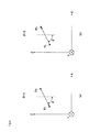
- FIG. 2A is a diagram illustrating an example of a velocity relative to the ground for explaining a relative approach angle in the embodiment of the present invention
- FIG. 2B is a diagram illustrating a relative approach angle in the embodiment of the present invention.
- FIG. 3 is a diagram for explaining the definition of coordinates in the embodiment of the present invention.
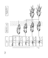
- FIG. 4 is a diagram for explaining combined optical flows in the embodiment of the present invention.
- FIG. 5 is a diagram showing the distances over which points in a three-dimensional space translational-move in a unit time in the embodiment of the present invention
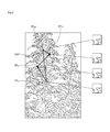
- FIG. 6 is a diagram for explaining a vanishing point in the embodiment of the present invention.
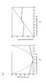
- FIG. 7A is a graph showing cost functions of robust estimation in the embodiment of the present invention.
- FIG. 7B is a graph showing influence functions of robust estimation in the embodiment of the present invention.
- FIG. 8 is a diagram showing an example image in which outliers easily occur in the embodiment of the present invention.
- FIG. 9A is a diagram for explaining the definition of a relative approach angle (where ⁇ 0) in the embodiment of the present invention.
- FIG. 9B is a diagram for explaining the definition of a relative approach angle (where ⁇ >0) in the embodiment of the present invention.
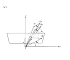
- FIG. 10 is a diagram showing the relationship between a relative approach angle and a vanishing point in the embodiment of the present invention.
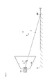
- FIG. 11 is a diagram for explaining a ground surface point according to a first example of a distance estimation method in the embodiment of the present invention.
- FIG. 12 is a diagram for explaining a calculation of the upper limit distance value according to the first example of a distance estimation method in the embodiment of the present invention.
- FIG. 13 is a diagram for explaining a risk calculation based on an estimated upper limit distance value in the embodiment of the present invention.
- FIG. 14 is a diagram for explaining a risk calculation based on an estimated distance value in the embodiment of the present invention.
- FIG. 15 is a diagram for explaining a modification of the risk calculation based on an estimated distance value in the embodiment of the present invention.
- FIG. 16 is a diagram for explaining a risk calculation based on a distance probability density function in the embodiment of the present invention.
- FIG. 17 is a diagram for explaining a risk calculation based on an estimated upper limit distance and an estimated distance distribution in the embodiment of the present invention.
- FIG. 18 is a table for explaining a risk calculation involving the TTC in the embodiment of the present invention.
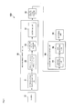
- FIG. 1 is a block diagram showing the structure of the moving object recognition system according to the embodiment of the present invention.
- the moving object recognition system 100 of this embodiment is a system that calculates the risk of a moving object colliding with its own vehicle, and reports the risk to the driver.
- the moving object recognition system 100 includes a camera 10 , a moving object detecting unit 20 , a relative approach angle estimating unit 30 , a collision risk calculating unit 40 , and a reporting unit 50 .
- the structure formed with the moving object detecting unit 20 , the relative approach angle estimating unit 30 , and the collision risk calculating unit 40 is realized by a computer executing a moving object recognition program of the embodiment of the present invention.
- the moving object recognition program may be stored in a storage medium, be read out from the storage medium by a computer, and be executed by the computer.
- the moving object recognition system 100 is briefly described.
- the camera 10 is mounted on the vehicle. While the vehicle is running, the camera 10 continuously captures images of the surroundings of the vehicle in regular cycles to generate images, and outputs the images to the moving object detecting unit 20 .
- the moving object detecting unit 20 uses the images sequentially input from the camera 10 , the moving object detecting unit 20 detects the moving object from the images. Since the vehicle (or the camera 10 ) is moving, the positions of the objects that are stationary on the ground vary every second in the images. From such images, the moving object detecting unit 20 detects an object that is moving relative to the ground, as a moving object.
- the relative approach angle estimating unit 30 estimates a relative approach angle of the relative moving direction of the detected moving object with respect to the vehicle.
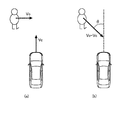
- FIGS. 2A and 2B are diagrams for explaining a relative approach angle in the embodiment of the present invention.
- a vehicle C is now running forward at a velocity v c
- a moving object O ahead of the vehicle C is moving at a velocity v o in a direction perpendicular to the traveling direction of the vehicle C.
- the relative approach angle ⁇ is determined to be the angle of v o -v c with respect to the traveling direction of the vehicle C, as shown in FIG. 2B .
- the relative approach angle estimating unit 30 estimates the relative approach angle ⁇ .
- the collision risk calculating unit 40 estimates the distance from its own vehicle to the moving object detected by the moving object detecting unit 20 . Based on the estimated distance and the relative approach angle detected by the relative approach angle estimating unit 30 , the collision risk calculating unit 40 calculates the risk of collision.
- the reporting unit 50 reports to the driver, based on the risk calculated by the collision risk calculating unit 40 . The details will be described below.
- the camera 10 is mounted on the vehicle, and captures images of the surroundings of the vehicle.
- the moving object recognition system 100 of this embodiment calculates and reports the risk of a moving object colliding with the vehicle, and therefore, the camera 10 is installed in the vehicle so as to capture images in the traveling direction of the vehicle.
- the camera 10 may be installed on the back side of the room mirror (the front side), for example, so as to capture images of the scenery ahead of the vehicle. Since the vehicle can move backward, the camera 10 may be installed near the license plate at the rear end, so as to capture images of the scenery behind the vehicle.
- the camera 10 is a monocular camera that has only one line of an optical system and an imaging element. The camera 10 continuously captures images in regular cycles (every 1/30 second, for example), and outputs image signals.
- the moving object detecting unit 20 groups (clusters) feature points of the same moving object in accordance with information about the coordinates and motion vectors (optical flows) of the feature points in the images (for details, see JP 2011-81613 A, which is incorporated herein by reference).
- an optical flow is a trajectory formed by tracking the same image patch (a small region of 5 ⁇ 5 pixels, for example) in a video or the like.
- the moving object detecting unit 20 also performs an operation to remove components generated by rotational motion of the camera 10 from the optical flows.
- the moving object detecting unit 20 includes a combined optical flow calculating unit 21 , a rotational motion and vanishing point estimating unit 22 , a background point removing unit 23 , and a grouping unit 24 .
- FIG. 3 is a diagram for explaining the definition of the coordinates in the embodiment of the present invention.
- the optical axis of the camera 10 is assumed to be parallel to the road surface.
- the optical axis of the camera 10 is set as the Z-axis, the vertically downward direction is the Y-axis, and the X-axis is defined by the right-handed coordinate system.
- the point of origin (0, 0, 0) is the optical center of the camera 10 .
- generalization can be easily performed by introducing appropriate rotation matrixes even in a case where the optical axis of the camera 10 is not parallel to the road surface.
- f represents the focal length of the camera 10 , which is a known value.
- the combined optical flow calculating unit 21 extracts common feature points from images obtained by the camera 10 , and calculates the optical flow of each of the feature points (see J. Shi and C. Tomasi, “Good features to track”, IEEE CVPR, pp. 593-600, 1994, which is incorporated herein by reference).
- the LK method is used as the algorithm for calculating optical flows (see B. D. Lucas and T. Kanade, “An iterative image registration technique with an application to stereo vision,” IJCAI, pp. 674-679, 1981, which is incorporated herein by reference).
- An outlier generally means an unanticipated calculation result, and an outlier of an optical flow specifically means a trajectory that is wrongly tracked.
- the technique disclosed in U.S. Pat. No. 8,184,857 is robust over outliers of optical flows, but there are unusual cases where optical flows include the same vanishing point and external ratio within the margin of error, though the vanishing point and the external ratio are outliers. In such cases, the outliers are detected, resulting in a risk miscalculation.
- This embodiment provides an outlier removing method that requires only a small amount of calculation.
- optical flows formed by combining optical flows among a few adjacent frames are used in this embodiment, instead of the optical flows between two frames adjacent to each other.
- an optical flow between two frames adjacent to each other, or the vector from a feature point in a certain frame toward the same (the corresponding) feature point in the next frame is called a “single optical flow”.
- An optical flow obtained by connecting two or more single optical flows, or the vector from a feature point in a certain frame to the same (the corresponding feature point in a frame that is one or a predetermined number of frames away from the certain frame is called a “combined optical flow”.
- FIG. 4 is a diagram for explaining a combined optical flow in the embodiment of the present invention.
- images continuously captured by the camera 10 are shown in chronological order from the top in the left column, single optical flows are shown in the center column, and combined optical flows each formed by combining three single optical flows are shown in the right column.
- the combined optical flow calculating unit 21 combines the single optical flows of the same (the corresponding) feature points among a few frames, to calculate a combined optical flow.
- a single optical flow is generated by connecting the same feature points between two adjacent frames, and a combined optical flow is generated by connecting single optical flows.
- the rotational motion and vanishing point estimating unit 22 estimates a vanishing point from combined optical flows.
- a vanishing point is used as the intersection point between extended lines of trajectories of points in an image plane. If there are two or more moving objects, a vanishing point is estimated for each of the moving objects.
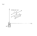
- FIG. 5 is a diagram showing the distances over which points in a three-dimensional space (points on a moving object) translational-move in a unit time (the velocity of the points in the three-dimensional space).
- V is ( ⁇ X, ⁇ Y, ⁇ Z)
- x(t) f(X+t ⁇ X)/(Z+t ⁇ Z)
- y(t) f(Y+t ⁇ Y)/(Z+t ⁇ Z)
- f ⁇ X/ ⁇ Z, f ⁇ Y/ ⁇ Z the coordinates of an image perspectively projected at time t
- the two-dimensional coordinates of the vanishing point are expressed as (f ⁇ X/ ⁇ Z, f ⁇ Y/ ⁇ Z).
- Points that converge at t ⁇ are points moving away from the camera, and points that converge at t ⁇ are points moving toward the camera.
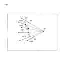
- FIG. 6 is a diagram for explaining the vanishing point.
- extended lines of combined optical flows COF 1 through COF 6 of feature points FP 1 through FP 6 intersect at one point, and this point is the vanishing point VP.
- the rotational motion and vanishing point estimating unit 22 extends the combined optical flows of respective feature points, and detect the point at which the combined optical flows intersect. The point is estimated to be the vanishing point.
- optical flows include outliers, the optical flows of moving objects, and the optical flows of background objects, it is appropriate to use robust estimation in estimating the vanishing point.
- Robust estimation is parameter estimation that is robust over outliers.
- the M-estimation see P. J. Huber and E. M. Ronchetti, “Robust Statistics, 2nd Edition,” Wiley Interscience, which is incorporated herein by reference) is used.
- the rotational motion and vanishing point estimating unit 22 may determine the vanishing point of combined optical flows by performing the simple operation described below. That is, the rotational motion and vanishing point estimating unit 22 records beforehand the position of the horizon in images captured by the camera 10 , and the point at which the horizon and combined optical flows intersect is set as the vanishing point of the trajectory of the point. This method is based on the fact that the vanishing point of the trajectory of a moving object exists on the horizon when the moving object and the camera 10 are moving parallel to a flat ground surface.
- the rotational motion and vanishing point estimating unit 22 also estimates the components of optical flows generated by rotational motion of the camera 10 , and removes the components from combined optical flows.
- v x x ⁇ ⁇ V z Z - f ⁇ ⁇ V x Z + v x r ⁇ ( ⁇ )
- v y y ⁇ ⁇ V z Z - f ⁇ ⁇ V y Z + v y r ⁇ ( ⁇ ) ( 1 )
- x fX/Z
- y fY/Z
- v x r and v y r are the components of the optical flow formed with the first-order term of the rotation of the camera 10 .
- the components v x r and v y r are expressed by the following equations (2):
- R(p F , ⁇ ) is an error function in the parameter space, and is 0 in an ideal state. That is, the equations (3) mean that extended lines of the optical flows of still points minus rotational components intersect at one point in an image (or at the focus of expansion (FOE)).
- the rotational motion and vanishing point estimating unit 22 in this embodiment uses the M-estimation expressed by the equation (4):
- FIG. 7A is a graph showing cost functions of robust estimation
- FIG. 7B is a graph showing influence functions of robust estimation.
- the dashed line indicates the L2-Norm
- the solid line indicates the Cauchy function.
- the Cauchy influence function defined by FIGS. 7A and 7B and the following equation (5) is used:
- the Cauchy influence function is not a monotonically increasing function where R>0, but starts decreasing at an extreme value. Accordingly, the influence on a solution of an input with a large error can be restrained to a small degree.
- the constant C in the equation (5) is 2.385. This value is set so as to achieve an efficiency that is 95% of the least square of a Gaussian distribution having the mean value of 0.
- the rotational motion and vanishing point estimating unit 22 uses iteratively reweighted least squares (IRLS) as the method of the M-estimation.
- IRLS iteratively reweighted least squares
- the cost function expressed by the equation (4) is transformed into the sum of squares of a weighted error, and a least square operation and a weight updating operation are alternately performed until the solution converges.
- the IRLS algorithm is as follows:
- the denominator 1.48 mad(R) in the resealing in step 3) is set so as to be equal to the standard deviation when R follows the normal distribution.
- the median absolute deviation (mad) is used instead of the standard deviation, to restrain the scale variation due to the existence of outliers to a small degree. Since the error is expressed in the form of the product of the FOE coordinates and the rotation motion, a non-linear least square is obtained in step 4).
- the rotational motion and vanishing point estimating unit 22 obtains a solution by using the Newton's method.
- the rotational motion and vanishing point estimating unit 22 removes the detected components generated by the rotational motion from combined optical flows.
- the background point removing unit 23 removes the combined optical flow as an object that does not move relative to the background or to the ground surface. Since a moving object that moves relative to the ground surface has a vanishing point in a position that is not in the background, the background point removing unit 23 removes the feature points having vanishing points in the background and the combined optical flows of those feature points, so as to detect each moving object having feature points with a vanishing point not belonging to the background.
- Combined optical flows which have been generated by the combined optical flow calculating unit 21 , from which the components generated by rotational motion have been removed by the rotational motion and vanishing point estimating unit 22 , and from which background points have been removed by the background point removing unit 23 , include outliers and the optical flows of feature points on a correctly tracked moving object.
- the grouping unit 24 groups the feature points and the combined optical flows of the feature points, while removing the outliers.
- the grouping unit 24 performs robust estimation of a vanishing point for the remaining feature points and the remaining combined optical flows.
- the grouping unit 24 groups, as a provisional group, the feature points and the combined optical flows having straight lines that are extended therefrom and pass through the vanishing point within an allowable range of error.
- the grouping unit 24 removes outliers from the provisional group, and determines an ultimate group.
- the grouping unit 24 first detects and removes outliers, based on the linearity of each of the combined optical flows.
- the grouping unit 24 further detects and removes outliers, based on TTC similarities calculated from the combined optical flows. This will be sequentially described below in detail.
- the trajectory of the feature point is a straight line, as long as the point is uniformly and linearly moving in a three-dimensional space.
- a uniform linear motion model is a suitable approximation. Therefore, determining whether single optical flows are linearly arranged is effective in removing outliers.
- FIG. 8 is a diagram showing an example image in which outliers easily occur.
- points FP t1 , FP t2 , FP t3 , and FP t4 which do not originally correspond to one another, are detected as corresponding feature points among frames. Such feature points and the optical flows connecting those feature points are outliers.
- the grouping unit 24 extracts the components perpendicular to a combined optical flow from each of the single optical flows, quantifies the degrees of linearity based on the extracted components, and compares the values with a threshold value, to detect outliers. Specifically, the grouping unit 24 determines whether each of the single optical flows constituting combined optical flows is linear in the following manner for each feature point.
- the grouping unit 24 calculates a unit vector perpendicular to the combined optical flow. Specifically, the unit vector is expressed as (V y (1:n), ⁇ V x (1:n))/sqrt(V x (1:n) 2 +V y (1:n) 2 ).
- the absolute value of the inner product of each of the single optical flows constituting the n-combined optical flow and the unit vector is then calculated, and the sum of n absolute values is obtained.
- the obtained sum is set as the indicator of linearity.
- the grouping unit 24 compares the linearity indicator with a predetermined threshold value, and excludes the feature points having higher linearity indicators than the threshold value and the combined optical flows of those feature points from the provisional group.
- the grouping unit 24 calculates the time to collision (TTC).
- TTC is the time until a three-dimensional point reaches the image plane while the point is moving toward the camera.
- the image plane has an infinite area.
- the TTC has a negative value.
- u is a two-dimensional vector representing the combined optical flow
- u x and u y are the x component and the y component of the vector
- equation u 2 u x 2 +u y 2 is satisfied
- u x is expressed by the following equation (6) using three-dimensional coordinates X and Z, and velocities ⁇ X and ⁇ Z:
- f the focal length of the camera 10 . Since the terms with the squares of velocities can be ignored, the following equation (7) is obtained:
- the x-coordinate x ⁇ of the vanishing point is a convergence position when it is infinitely going back in time (where the point is moving toward the camera). Therefore, the x-coordinate x ⁇ of the vanishing point is expressed by the following equation (8):
- TTC is represented by ⁇ T
- ⁇ T is determined by Z/( ⁇ Z) ( ⁇ Z ⁇ 0, if the feature point is moving toward the camera). Since the y component u y of the optical flow can be calculated in the same manner, the following equation (9) is obtained:
- p represents the coordinates of a feature point in the image
- p ⁇ represents the coordinates of the vanishing point of the trajectory of the point in the image
- “.” is the inner product operator
- the grouping unit 24 calculates the time to collision ⁇ T n from the n-combined optical flow (V x (1:n), V y (1:n)) of each feature point, using the equation (10).
- the grouping unit 24 also calculates ⁇ T n-1 , ⁇ T n-2 , . . . of the same feature point in the same manner as ⁇ T n .
- ⁇ T n , ⁇ T n-1 , . . . are equal to one another, as long as the point is uniformly and linearly moving in a three-dimensional space.
- ⁇ T n , ⁇ T n-1 , . . . are similar to one another. If ⁇ T n , ⁇ T n-1 , . . . are not similar, the point has been wrongly tracked, and can be determined to be an outlier.
- the grouping unit 24 determines the similarity among the times to collision ⁇ T n , ⁇ T n-1 , . . . for each of the feature points of n-combined optical flows, and compares the similarity with a predetermined threshold value.
- the grouping unit 24 excludes the feature points having smaller values than the threshold value and the combined optical flows of those feature points from the provisional group.
- (j 1, . . . , n ⁇ 1). If there is at least one “j” satisfying D>D th , the feature point(s) and the combined optical flow(s) of the feature point(s) are excluded from the group.
- D th is the predetermined threshold value.
- the grouping unit 24 groups combined optical flows by removing outliers according to the above described method based on linearity and the method based on the TTC similarity.
- the feature points of combined optical flows grouped together are feature points of one moving object.
- the grouping unit 24 detects a moving object by grouping feature points in the above manner.
- the grouping unit 24 may remove outliers by using only the method based on linearity or using only the method based on TTC similarity.
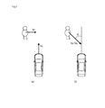
- FIGS. 9A and 9B are diagrams for explaining the definition of a relative approach angle.
- FIG. 9A illustrates a case where ⁇ 0
- FIG. 9B illustrates a case where ⁇ >0.
- the angle expressed by the following equation (11) is defined as the relative approach angle:
- FIG. 10 is a diagram showing the relationship between relative approach angles and a vanishing point.
- the trajectories of those points after perspective projection have a vanishing point.
- the vector V from the optical center toward the vanishing point VP is (f ⁇ X/ ⁇ Z, f ⁇ Y/ ⁇ Z, f)
- the vector V is a constant number of times (f/ ⁇ Z times) larger than the velocity vectors of the points Pa and Pb
- the relative approach angle estimating unit 30 calculates an estimated value of the relative approach angle of a moving object detected by the moving object detecting unit 20 with respect to the vehicle.
- the collision risk calculating unit 40 calculates the risk of a moving object colliding with its own vehicle, based on the relative approach angle, the TTC, and an estimated distance value.
- the collision risk calculating unit 40 includes a distance estimating unit 41 and a risk calculating unit 42 .
- the distance estimating unit 41 estimates the Z-direction distance from its own vehicle to a moving object (hereinafter referred to simply as the “distance”). Based on the distance estimated by the distance estimating unit 41 , the risk calculating unit 42 calculates the risk of the moving object colliding with its own vehicle.
- the methods described below can be used by the distance estimating unit 41 to estimate the distance.
- the distance estimating unit 41 may estimate the distance by using one of the methods described below, or may estimate the distance by using two or more of the methods.
- the estimated distance is to be used by the risk calculating unit 42 to calculate a degree of risk. Therefore, the distance estimating unit 41 estimates the distance required by the method to be used by the risk calculating unit 42 to calculate a degree of risk. The following is a description of those estimation methods.
- the distance estimating unit 41 estimates the upper limit of the distance to a moving object.
- FIG. 11 is a diagram for explaining the ground surface point according to a first example of a distance estimation method.
- FIG. 12 is a diagram for explaining the calculation of the upper limit value of the distance according to the first example of a distance estimation method.
- the distance estimating unit 41 selects the feature point having the largest y-coordinate value among feature points grouped together (the selected feature point will be hereinafter referred to as the “lowest feature point”), and calculates the coordinates of the intersection point (hereinafter referred to as the “ground surface point”) GP between the straight line connecting the lowest feature point to the optical center and the ground surface G
- the Z-coordinate of the three-dimensional point indicated by the lowest feature point is smaller than the Z-coordinate of the ground surface point GP. If the distances between feature points among the feature points grouped together are sufficiently shorter than the distance from the camera 10 , the Z-coordinate of the ground surface point GP can be regarded as the upper limit value of the Z-coordinates of the feature points.
- He represents the height of the camera 10 from the ground surface
- y_max represents the y-coordinate of the lowest feature point
- f represents the focal length or the distance from the optical center of the camera 10 to the image plane IP. It should be noted that this method can be used only when y_max has a positive value.
- the distance estimating unit 41 calculates Hc*f/y_max as the upper limit value D1 of the distance.
- the distance estimating unit 41 identifies a point representing a moving object, and directly estimates the distance by using the translational motion velocity of its own vehicle and the time to collision TTC of the representative point.
- the distance estimating unit 41 selects a representative point from feature points grouped together as a moving object.
- the TTC of the feature point selected as the representative point has been determined by the moving object detecting unit 20 , and therefore, is used herein.
- ⁇ T represents the TTC
- V c represents the translational motion velocity of the vehicle
- the distance estimating unit 41 identifies a point representing a moving object, and determines a distance probability distribution by using the time to collision TTC of the representative point.
- the distance estimating unit 41 selects a representative point from feature points grouped together as a moving object.
- the TTC of the feature point selected as the representative point has been determined by the moving object detecting unit 20 , and therefore, is used herein.
- the distance estimating unit 41 provisionally determines the probability distribution of the velocity of a moving object in the Z direction.
- An object that moves at a different relative approach angle from the relative approach angle of background points has an angle that is not zero with respect to the direction of translational motion of the vehicle. It is empirically appropriate to determine a normal distribution with an average of 0 to be the probability distribution of the Z-direction velocity of such a moving object.
- the distance estimating unit 41 stores beforehand the average ⁇ V of the Z-direction velocity ⁇ Z of the representative point of a moving object, and also stores a fixed value of 3 km/h, for example, as the standard deviation ⁇ .
- the probability distribution of the Z-direction velocity ⁇ Z of the representative point of the moving object conforms to the normal distribution with the average ⁇ V and the standard deviation ⁇ .
- ⁇ T represents the TTC
- the distance estimating unit 41 determines the normal distribution with the average ⁇ T( ⁇ V) and the standard deviation ⁇ T ⁇ to be the probability distribution of the distance Z to the representative point.
- the risk calculating unit 42 defines a danger zone based on the relative approach angle ⁇ estimated by the relative approach angle estimating unit 30 , and then calculates the risk of a moving object colliding with its own vehicle.
- a danger zone is a region in the X-Z plane. In such a danger zone, when a point in the X-Z plane moves toward the vehicle at a certain relative approach angle, the point collides with the vehicle. However, the region occupied by its own vehicle in the X-Z plane is a non-danger zone.
- the risk calculating unit 42 calculates the risk by using a method compatible with the distance estimation method used by the distance estimating unit 41 . The following is a description of risk calculations.
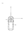
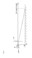
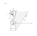
- FIG. 13 is a diagram for explaining a risk calculation based on an estimated value of the upper limit of the distance.
- a danger zone DZ extends in a direction tilted at the relative approach angle ⁇ with respect to the traveling direction of the vehicle C (or the Z-axis direction), and has a width equivalent to the width of the vehicle C in a direction perpendicular to the tilted direction.
- the danger zone DZ is closer to the vehicle C than the estimated upper limit D1 of the distance.
- the risk calculating unit 42 sets a danger zone that is tilted at the relative approach angle ⁇ to the right.
- the risk calculating unit 42 sets a danger zone that is tilted at the relative approach angle ⁇ to the left.
- a ray formed on the X-Z plane by orthographically projecting a straight line passing through the optical center and a point in the image is called an XZ ray.
- FIG. 13 an XZ ray ( 1 ) and an XZ ray ( 2 ) are shown.
- the risk calculating unit 42 identifies a point representing the moving object, and calculates the risk of the representative point colliding with the vehicle C by using the XZ ray of the representative point and the danger zone DZ. Specifically, the risk calculating unit 42 calculates the proportion of the line segment existing in the danger zone DZ to the line segment of the XZ ray of the representative point between the point of origin and the upper limit value D1. The value of the calculated proportion is set as the risk. In the example illustrated in FIG. 13 , the risk in the XZ ray ( 1 ) is expressed as L1/(L1+L2), and the risk in the XZ ray ( 2 ) is 100% (the maximum) as the entire XZ ray ( 2 ) is in the danger zone DZ.
- the risk becomes higher, as the difference between the direction at the relative approach angle ⁇ and the direction of the positional vector of the representative point becomes smaller (or the degree of coincidence becomes higher) in the X-Z plane.
- the risk becomes higher, as the vanishing point and the representative point become closer to each other in the image.
- the risk calculating unit 42 may turn the proportion into a discrete value by rounding or the like, and calculates the risk as a level among several different levels. In this case, the level of risk is higher where the proportion is higher.
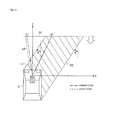
- FIG. 14 is a diagram for explaining a risk calculation based on an estimated distance value.
- the risk calculating unit 42 sets a danger zone DZ that extends in a direction tilted at the relative approach angle ⁇ with respect to the traveling direction of the vehicle C (or the Z-axis direction), and has a width equivalent to the width of the vehicle C in a direction perpendicular to the tilted direction, as in the above described calculation example.
- the risk calculating unit 42 sets a danger zone that is tilted at the relative approach angle ⁇ to the right, as in the above described example.
- the risk calculating unit 42 sets a danger zone that is tilted at the relative approach angle ⁇ to the left, as in the above described example. In this example, however, the upper limit of the danger zone DZ is not to be set. Since the distance D2 to the representative point is estimated in this example, the intersection point between the XZ ray of the representative point and the estimated distance value D2 is the (X, Z) coordinates of the representative point. Accordingly, the risk is determined from whether the (X, Z) coordinates of the representative point are in the danger zone DZ. That is, when the (X, Z) coordinates of the representative point are in the danger zone DZ, it is determined that there is a risk. When the (X, Z) coordinates of the representative point are not in the danger zone DZ, it is determined that there is no risk.
- the intersection point between the XZ ray ( 1 ) and the estimated distance value D2 is outside the danger zone DZ. Therefore, as for the XZ ray ( 1 ), it is determined that there is no risk.
- the intersection point between the XZ ray ( 2 ) and the estimated distance value D2 is in the danger zone DZ. Therefore, as for the XZ ray ( 2 ), it is determined that there is a risk.
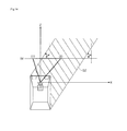
- FIG. 15 is a diagram for explaining a modification of this example.
- a danger zone DZ is divided into levels in a stepwise fashion, as shown in FIG. 15 .
- a danger zone DZ 1 includes a larger proportion of the front portion (including the front bumper) of the vehicle C, and has a high risk level.
- a danger zone DZ 2 having an intermediate risk level is set outside the danger zone DZ 1 .
- a danger zone DZ 3 having a relatively low risk level is set around the danger zone DZ 2 .
- the risk calculating unit 42 determines the risk level based on which danger zone includes the intersection point between the XZ ray and the estimated distance value D2, in the same manner as above.
- the dividing of the danger zone into a few levels may be applied to the first example and to the third and fourth examples described later.
- the risk calculation is performed so that the risk becomes higher as the difference between the direction at the relative approach angle ⁇ and the direction of the positional vector of the representative point becomes smaller (or the degree of coincidence becomes higher) in the X-Z plane, or the risk becomes higher as the vanishing point and the representative point become closer to each other in the image, as in the above described example.
- FIG. 16 is a diagram for explaining a risk calculation based on a distance probability distribution.
- the risk calculating unit 42 calculates a boundary point BP (X BP , Z BP ) existing exactly on the boundary between a danger zone DZ and a safety zone SZ on the XZ ray of a representative point.
- the risk calculating unit 42 divides the distance probability distribution estimated by the distance estimating unit 41 into two portions, with the Z-coordinate (Z BP ) of the boundary point BP being the boundary.
- the value of the integral S1 of the probability density function of the probability distribution on the side of the danger zone DZ in the area of the entire probability distribution indicates the probability that the representative point is in the danger zone DZ
- the value of the integral S2 of the probability density function of the probability distribution on the side of the safety zone SZ in the area of the entire probability distribution indicates the probability that the representative point is in the safety zone SZ.
- the risk calculating unit 42 determines the risk in the representative point to be the probability that the representative point is in the danger zone DZ. If the distance distribution estimated by the distance estimating unit 41 is a normal distribution, an error function can be used to obtain the integral of the distance distribution. The risk calculating unit 42 may set the probability as the risk, or determine the risk from a discrete level.
- the risk calculation is performed so that the risk becomes higher as the difference between the direction at the relative approach angle ⁇ and the direction of the positional vector of the representative point becomes smaller (or the degree of coincidence becomes higher) in the X-Z plane, or the risk becomes higher as the vanishing point and the representative point become closer to each other in the image, as in the above described examples.
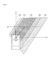
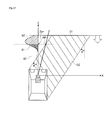
- FIG. 17 is a diagram for explaining a risk calculation based on an estimated upper limit of the distance and an estimated distance distribution.
- the distance estimating unit 41 calculates the upper limit of the distance, and determines the distance probability distribution.
- the risk calculating unit 42 cuts the distance probability distribution determined by the distance estimating unit 41 at the estimated value D1 of the upper limit of the distance determined by the distance estimating unit 41 , to form a single cutoff normal distribution.
- the risk calculating unit 42 uses the distribution below the upper limit D1 of the distance, calculates a boundary point BP (X BP , Z BP ) existing exactly on the boundary between a danger zone DZ and a safety zone SZ on the XZ ray of the representative point in the same manner as in the third example.
- the risk calculating unit 42 divides the single cutoff normal distribution into two portions, with the Z-coordinate (Zap) of the boundary point BP being the boundary.
- the value of the integral of the probability density function of the XZ ray of the representative point within the distance range up to the upper limit value D1 of the distance is the value of the integral of the single cutoff normal distribution, and is expressed as S1+S2′, which is normally not 100%.
- the value of the integral of the probability density function of the XZ ray of the representative point within the distance range in the danger zone DZ is S1 shown in FIG. 17 .
- the proportion of S1 to S1+S2′ (S1/(S1+S2′)) is the risk in the representative point.
- the risk calculating unit 42 may calculate S1/(S1+S2′) as the risk, or determine the risk from a discrete level, as in the above described example.
- the risk calculation is performed so that the risk becomes higher as the difference between the direction at the relative approach angle ⁇ and the direction of the positional vector of the representative point becomes smaller (or the degree of coincidence becomes higher) in the X-Z plane, or the risk becomes higher as the vanishing point and the representative point become closer to each other in the image, as in the above described examples.
- the risk is calculated in such a manner that the risk becomes higher as the difference between the direction at the relative approach angle ⁇ and the direction of the positional vector of the representative point becomes smaller (or the degree of coincidence becomes higher) in the X-Z plane, or the risk becomes higher as the vanishing point and the representative point become closer to each other in the image.
- the collision risk calculating unit 40 may calculate the risk as the difference in angle between the direction at the relative approach angle ⁇ and the direction of the positional vector of the representative point, or the distance between the vanishing point and the representative point in the image.
- This modification can be applied to the above described first through fourth calculation examples.
- the TTC is also used in calculating the risk in any of the above described first through fourth calculation examples.
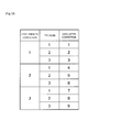
- An object having a short TTC of course has a higher degree of risk than an object having a long TTC. Therefore, each risk calculated in the first through fourth calculation examples is corrected based on the length of the TTC, so that the risk becomes higher as the TTC becomes shorter.
- the risk calculated in any of the first through fourth calculation examples is multiplied by a TTC level, which is the reciprocal of the TTC, for example.
- a TTC level which is the reciprocal of the TTC, for example.
- the risk can be corrected.
- the value of the TTC is divided into three levels, as shown in FIG. 18 , and the risk can be corrected by the combination of the risk level and the TTC level, for example.
- the distance estimating unit 41 and/or the risk calculating unit 42 selects a representative point from feature points grouped as a moving object, and then estimates the distance and/or calculates the risk.
- the distance estimating unit 41 and/or the risk calculating unit 42 may identify two or more representative points of one moving object, estimate the distances to the respective representative points and/or calculate the risks in the respective representative points, calculate the average of the calculated risks in the representative points, and set the average as the risk of the moving object colliding with the vehicle.
- the representative point may not be one of the feature points grouped as the moving object, but may be a point determined based on the feature points, such as the midpoint, the gravity point, or the like among the feature points.
- the reporting unit 50 reports a danger to the driver in accordance with the risk of collision calculated by the collision risk calculating unit 40 .
- the moving object recognition system 100 includes a display such as a head-up display. The image captured by the camera 10 is displayed on the display in real time. A rectangular frame surrounding the feature points grouped by the moving object detecting unit 20 is superimposed on the image. At this point, the reporting unit 50 changes the color or the thickness of the rectangular frame in accordance with the risk. Also, the reporting unit 50 may report the danger of collision to the driver with sound. In this case, as the risk becomes higher, the sound level may be increased or the frequency of the sound may be increased to alert the driver.
- An automatic braking system may be used together with the reporting unit 50 , or instead of the reporting unit 50 .
- the automatic braking system receives the information about the risk calculated by the collision risk calculating unit 40 , and performs braking on the vehicle. With this automatic braking system, automatic braking can be performed on the vehicle in a dangerous situation.
- a storage device may also be used together with the reporting unit 50 , or instead of the reporting unit 50 .
- the storage device stores the information about the risk calculated by the collision risk calculating unit 40 , together with the positional information and the temporal information corresponding to the information about the risk. By referring to the record of the risk, the danger zone and time can be recognized, and the state of safe driving by the driver can be checked.
- the moving object recognition system 100 of the embodiment of the present invention obtains continuous single-view images with a camera installed in the vehicle, and groups together the feature points in the images based on a vanishing point. In this manner, the moving object recognition system 100 detects a moving object. Based on the images, the moving object recognition system 100 estimates a relative approach angle, and calculates the risk of the moving object colliding with the vehicle by using the relative approach angle. The risk is an indicator with a physical meaning. As the risk is reported to the driver, the driver can instinctively recognize a dangerous situation, or can perform a control operation in accordance with the dangerous situation.
- the moving object recognition system 100 of the embodiment of the present invention calculates the risk in such a manner that the risk becomes higher as the difference between the direction at the relative approach angle and the direction of the positional vector of the detected moving object becomes smaller. Accordingly, the risk of collision can be accurately calculated.
- the moving object recognition system 100 of the embodiment of the present invention may use a distance sensor, as well as the above described structure. In this case, the moving object recognition system 100 compares the information about a moving object trajectory obtained by the distance sensor with the information about the relative approach angle, the time to collision, the estimated distance to the moving object, and the like obtained by the above described structure. By doing so, the moving object recognition system 100 can increase the reliability of the detection. In the case where the distance sensor is also used, the distance to the moving object is also obtained by the distance sensor, and is used to improve the accuracy of calculating the risk of collision of the moving object.
- the present invention has an effect to calculate the risk of a moving object colliding with the vehicle, and uses the calculated risk as the information useful for the driver of the vehicle to drive safely.
- the present invention is effectively applied to a moving object recognition system that recognizes a moving object by using single-view images, and the likes.
Landscapes
- Physics & Mathematics (AREA)
- General Physics & Mathematics (AREA)
- Engineering & Computer Science (AREA)
- Multimedia (AREA)
- Theoretical Computer Science (AREA)
- Traffic Control Systems (AREA)
- Image Processing (AREA)
- Image Analysis (AREA)
- Closed-Circuit Television Systems (AREA)
Abstract
Description
- The disclosure of Japanese Patent Application No. 2012-169709, filed on Jul. 31, 2012, is incorporated herein by reference.
- 1. Field of the Invention
- The present invention relates to moving object recognition systems, moving object recognition programs, and moving object recognition methods for recognizing moving objects by using single-view images.
- 2. Description of the Related Art
- There have been known moving object recognition systems that recognize moving objects existing near a vehicle, and then report to or alert the driver or automatically perform braking on the vehicle (hereinafter referred to simply as “reporting”). The distance from the vehicle to a moving object can be directly measured by using a distance sensor such as a millimeter-wave radar, or can be measured by performing image processing with a stereo camera. The moving direction of the moving object and the velocity of the moving object relative to the vehicle can be determined by arranging measured distances in chronological order and then analyzing those distances. As the moving direction of the moving object and the velocity of the moving object relative to the vehicle are determined, the probability (risk) of the moving object colliding with the vehicle can be calculated, and reporting can be performed in accordance with the risk.
- As simpler and less expensive moving object recognition systems, there also have been systems that recognize a moving body with a monocular camera that has only one line of an optical system and an imaging element. Such a system continuously captures images with a monocular camera, to obtain single-view images arranged in chronological order. The technique disclosed in U.S. Pat. No. 8,184,857 which is incorporated herein by reference is known as a technique for detecting a moving object from such single-view images.
- By the technique disclosed in U.S. Pat. No. 8,184,857, feature points are extracted from each of single-view images arranged in chronological order, and the feature points are grouped by moving objects, based on the motion vectors (optical flows) of the extracted feature points. The grouping is performed based on variations in the convergence properties of the optical flows to a vanishing point and the external ratios. In this manner, accurate moving object detection can be performed, even if there is an inaccurately-calculated optical flow.
- In an in-vehicle moving object recognition system, it is preferable to report only the risk of a moving object colliding with or rushing toward the vehicle to the driver, without reporting any moving object with no risk of collision to the driver. This is because reporting every moving object bothers the driver, and might adversely affect the driving.
- In such an in-vehicle moving object recognition system, the reliability of a result of recognition processing does not always match an actual risk of collision. That is, the risk of collision might be zero, though the result of recognition processing shows a high level of reliability, and vice versa. Information that is useful to most drivers is not the information about the reliability of recognition processing but the information about the risk of a recognized moving object colliding with his/her own vehicle.
- The present invention has been made in view of the above problems, and the object thereof is to provide a moving object recognition system that senses a danger of collision of a moving object by using a monocular camera, instead of a relatively expensive sensor such as a stereo camera or a distance sensor.
- According to an aspect of the present invention, a moving object recognition system includes: a camera configured to capture a plurality of continuous single-view images, the camera being installed in a vehicle; a moving object detecting unit configured to detect a moving object from the images captured by the camera; a relative approach angle estimating unit configured to estimate a relative approach angle of the moving object detected by the moving object detecting unit with respect to the camera; and a collision risk calculating unit configured to calculate a risk of the moving object colliding with the vehicle, based on a relationship between the relative approach angle and a moving object direction from the camera toward the moving object.
- With this structure, the risk of a moving object colliding with the vehicle can be obtained as information useful for the driver of the vehicle to drive safely. Also, the risk calculation is performed with a relatively inexpensive mechanism such as a monocular camera, instead of a relatively expensive mechanism such as a stereo camera. Accordingly, the costs can be lowered.
- In the moving object recognition system, the collision risk calculating unit may make the risk higher as the difference between the relative approach angle and the moving object direction becomes smaller.
- When the relative approach angle matches the moving object direction, the moving object is heading toward the vehicle in a relative manner. In view of this, the risk becomes higher, as the difference between the relative approach angle and the moving object direction becomes smaller. Accordingly, the risk of a moving object colliding with the vehicle can be accurately calculated by the above structure.
- In the moving object recognition system, the collision risk calculating unit may set a danger zone based on the relative approach angle, and calculate the risk based on a probability of the moving object existing in the danger zone.
- With this structure, the risk of a moving object colliding with the vehicle can be accurately calculated by using not only the relative approach angle of the moving object with respect to the vehicle, but also the danger zone that is set based on the relative approach angle.
- In the moving object recognition system, the danger zone may be set in an X-Z plane where the camera is the point of origin, an optical axis direction of the camera is a Z direction, a vertical direction is a Y direction, and a horizontal direction is an X direction, and may be a region extending from the vehicle in a direction at the relative approach angle and having a width of the vehicle.
- With this structure, the danger zone is designed to have a width equivalent to the width of the vehicle and extend from the vehicle in the direction at the relative approach angle. Accordingly, the risk of collision with any portion of the vehicle can be calculated.
- In the moving object recognition system, the collision risk calculating unit may include: a distance estimating unit configured to estimate an upper limit value of a distance from the camera to the moving object in the Z direction; and a risk calculating unit configured to calculate the risk by determining a proportion of a line segment existing in the danger zone to a line segment of an XZ ray between the camera and the upper limit value, the XZ ray being a line segment formed by orthographically projecting a straight line onto the X-Z plane, the straight line passing through the camera and the moving object in the images located at a focal distance from the camera.
- With this structure, an upper limit is set on the danger zone. Accordingly, even if the distance to a moving object cannot be determined, the probability of the moving object existing in the danger zone can be calculated by identifying the moving object direction.
- In the moving object recognition system, the moving object detecting unit may include: an optical flow calculating unit configured to extract a plurality of feature points from the images, and calculate optical flows of the extracted feature points; and a grouping unit configured to group, among the extracted feature points, a plurality of feature points having the optical flows extended therefrom and converging at a vanishing point as a plurality of feature points existing on the moving object, and the distance estimating unit may select a lowest feature point having the lowest height among the grouped feature points existing on the moving object, and estimate the upper limit value of the distance from the camera to the moving object in the Z direction by calculating a Z-coordinate of a ground surface point that is an intersection point between a straight line connecting the lowest feature point to the optical center and a ground surface on which the vehicle is running.
- The assumption that the distances between feature points grouped as a moving object are sufficiently smaller than the distance from the camera is valid in a moving object recognition system that recognizes moving objects existing near the vehicle. Accordingly, the upper limit of the distance to a moving object can be accurately estimated by a simple calculation in this structure.
- In the moving object recognition system, the collision risk calculating unit may include: a distance estimating unit configured to estimate a distance from the camera to the moving object in the Z direction; and a risk calculating unit configured to make the risk higher when a point at the estimated distance from the camera on an XZ ray exists in the danger zone than when the point does not exist in the danger zone, the XZ ray being a line segment formed by orthographically projecting a straight line onto the X-Z plane, the straight line passing through the camera and the moving object in the images located at a focal distance from the camera.
- With this structure, the distance to a moving object is estimated. Accordingly, it is possible to determine whether the moving object exists in the danger zone, instead of the probability of the moving object existing in the danger zone. If the moving object is determined to be in the danger zone, the risk is calculated to be high. The risk may be divided into a few levels in accordance with portions of the vehicle with which the moving object collides.
- In the moving object recognition system, the moving object detecting unit may include: an optical flow calculating unit configured to extract a plurality of feature points from the images, and calculate optical flows of the extracted feature points; and a grouping unit configured to group, among the extracted feature points, a plurality of feature points having the optical flows extended therefrom and converging at a vanishing point as a plurality of feature points existing on the moving object, and the distance estimating unit may calculate, based on the vanishing point, a time to collision of the moving object with the vehicle, and estimate, based on the time to collision and a velocity of the vehicle, the distance from the camera to the moving object in the Z direction.
- A moving object that is dangerous to a running vehicle is a moving object that moves in a direction perpendicular to the traveling direction of the vehicle (for example, a moving object that goes by the vehicle is not so dangerous). The assumption that a moving object is translationally moving in a direction perpendicular to the vehicle (or the velocity component of the moving object in the direction of the optical axis of the camera is zero) is valid in a moving object recognition system that recognizes moving objects existing near the vehicle. Accordingly, the distance to a moving object can be accurately estimated by a simple calculation in this structure.
- In the moving object recognition system, the collision risk calculating unit may include: a distance estimating unit configured to determine a probability distribution of a distance from the camera to the moving object in the Z direction; and a risk calculating unit configured to calculate the risk, based on a value of the integral of a probability density function of the probability distribution within a distance range in which an XZ ray exists in the danger zone, the XZ ray being a line segment formed by orthographically projecting a straight line onto the X-Z plane, the straight line passing through the camera and the moving object in the images located at a focal distance from the camera.
- With this structure, a distance is estimated not in the form of a single value, but in the form of a probability distribution. Accordingly, the risk can be accurately calculated in accordance with the proportion of the value of the integral of the probability density function of the probability distribution in the danger zone.
- In the moving object recognition system, the moving object detecting unit may include: an optical flow calculating unit configured to extract a plurality of feature points from the images, and calculate optical flows of the extracted feature points; and a grouping unit configured to group, among the extracted feature points, a plurality of feature points having the optical flows extended therefrom and converging at a vanishing point as a plurality of feature points existing on the moving object, and the distance estimating unit may calculate, based on the vanishing point, a time to collision of the moving object with the vehicle, and determine, based on the time to collision, the probability distribution of the distance in compliance with a predetermined normal distribution.
- The assumption that a distance probability distribution is a normal distribution is valid in a moving object recognition system that recognizes moving objects existing near the vehicle. Accordingly, the probability distribution of the distance to a moving object can be accurately determined by a simple calculation in this structure.
- In the moving object recognition system, the collision risk calculating unit may include: a distance estimating unit configured to estimate an upper limit value of a distance from the camera to the moving object in the Z direction, and determine a probability distribution of the distance from the camera to the moving object in the Z direction; and a risk calculating unit configured to calculate the risk, based on a proportion of a value of the integral of a probability density function of the probability distribution within a distance range in which an XZ ray exists in the danger zone to a value of the integral of a probability density function of the probability distribution within a distance range up to the upper limit value, the XZ ray being a line segment formed by orthographically projecting a straight line onto the X-Z plane, the straight line passing through the camera and the moving object in the images located at a focal distance from the camera.
- With this structure, a distance is estimated not in the form of a single value, but in the form of a probability distribution. Furthermore, the portion above an estimated upper limit value is cut off from the probability distribution. Accordingly, the risk can be accurately calculated in accordance with the proportion of the value of the integral of the probability density function in the danger zone to the value of the integral of the probability density function in the remaining range.
- In the moving object recognition system, the moving object detecting unit may include: an optical flow calculating unit configured to extract a plurality of feature points from the images, and calculate optical flows of the extracted feature points; and a grouping unit configured to group, among the extracted feature points, a plurality of feature points having the optical flows extended therefrom and converging at a vanishing point as a plurality of feature points existing on the moving object, and the distance estimating unit may select a lowest feature point having the lowest height among the grouped feature points existing on the moving object, estimate the upper limit value of the distance from the camera to the moving object in the Z direction by calculating a Z-coordinate of a ground surface point that is an intersection point between a straight line connecting the lowest feature point to the optical center and a ground surface on which the vehicle is running, calculate, based on the vanishing point, a time to collision of the moving object with the vehicle, and determine, based on the time to collision, the probability distribution of the distance in compliance with a predetermined normal distribution.
- The assumption that the distances between feature points grouped as a moving object are sufficiently smaller than the distance from the camera is valid in a moving object recognition system that recognizes moving objects existing near the vehicle. Accordingly, the upper limit of the distance to a moving object can be accurately estimated by a simple calculation in this structure. Also, the assumption that a distance probability distribution is a normal distribution is valid in a moving object recognition system that recognizes moving objects existing near the vehicle. Accordingly, the probability distribution of the distance to a moving object can be accurately determined by a simple calculation in this structure.
- In the moving object recognition system, the collision risk calculating unit may divide the danger zone into a plurality of levels, and set the levels in a stepwise fashion.
- With this structure, the risk can be calculated in accordance with the influence of collision with each portion of the vehicle.
- According to another aspect of the present invention, a moving object recognition system includes: a camera configured to capture a plurality of continuous single-view images, the camera being installed in a vehicle; a moving object detecting unit configured to detect a moving object by extracting a plurality of feature points from the images captured by the camera, generating optical flows of the extracted feature points, grouping, among the extracted feature points, a plurality of feature points having the optical flows extended therefrom and converging at a vanishing point, and detecting the grouped feature points as the moving object; and a collision risk calculating unit configured to calculate a risk of the moving object colliding with the vehicle, and wherein the collision risk calculating unit calculates the risk in such a manner that the risk of the moving object located at a short distance from the vanishing point in the images becomes higher than the risk of the moving object at a long distance from the vanishing point in the images.
- With this structure, the risk of a moving object colliding with the vehicle can also be obtained as information useful for the driver of the vehicle to drive safely. Here, the risk calculation is performed with a relatively inexpensive mechanism such as a monocular camera, instead of a relatively expensive mechanism such as a stereo camera. Accordingly, the costs can be lowered. Furthermore, the risk can be calculated by a simple calculation based on the distance between the vanishing point and the moving object in images.
- In the moving object recognition system, the collision risk calculating unit may calculate a risk of a representative point with the vehicle, the representative point being one of the feature points existing on the moving object or a point determined from the feature points existing on the moving object.
- With this structure, an appropriate representative point can be identified as the position of a moving object.
- The moving object recognition system may further including a reporting unit configured to report a danger to a driver of the vehicle in accordance with the risk calculated by the collision risk calculating unit.
- With this structure, it is possible to alert the driver in accordance with the risk of a moving object colliding with the vehicle.
- In the moving object recognition system, the collision risk calculating unit may correct the risk, based on a time to collision of the moving object with the vehicle.
- With this structure, the risk can be more accurately calculated by using a time to collision as well.
- According to an aspect of the present invention, a storage medium has stored therein a moving object recognition program causing a computer to function as: a moving object detecting unit configured to detect a moving object from a plurality of continuous single-view images captured by a camera installed in a vehicle; a relative approach angle estimating unit configured to estimate a relative approach angle of the moving object detected by the moving object detecting unit with respect to the camera; and a collision risk calculating unit configured to calculate a risk of the moving object colliding with the vehicle, based on a relationship between the relative approach angle and a moving object direction from the camera toward the moving object.
- With this structure, the risk of a moving object colliding with the vehicle can also be obtained as information useful for the driver of the vehicle to drive safely. Here, the risk calculation is performed with a relatively inexpensive mechanism such as a monocular camera, instead of a relatively expensive mechanism such as a stereo camera. Accordingly, the costs can be lowered.
- According to another aspect of the present invention, a storage medium has stored therein a moving object recognition program causing a computer to function as: a moving object detecting unit configured to detect a moving object by extracting a plurality of feature points from a plurality of continuous single-view images captured by a camera installed in a vehicle, generating optical flows of the extracted feature points, grouping, among the extracted feature points, a plurality of feature points having the optical flows extended therefrom and converging at a vanishing point, and detecting the grouped feature points as the moving object; and a collision risk calculating unit configured to calculate a risk of the moving object colliding with the vehicle in such a manner that the risk of the moving object located at a short distance from the vanishing point in the images becomes higher than the risk of the moving object at a long distance from the vanishing point in the images.
- With this structure, the risk of a moving object colliding with the vehicle can also be obtained as information useful for the driver of the vehicle to drive safely. Here, the risk calculation is performed with a relatively inexpensive mechanism such as a monocular camera, instead of a relatively expensive mechanism such as a stereo camera. Accordingly, the costs can be lowered. Furthermore, the risk can be calculated by a simple calculation based on the distance between the vanishing point and the moving object in images.
- According to an aspect of the present invention, a moving object recognition method includes: capturing a plurality of continuous single-view images with a camera installed in a vehicle; detecting a moving object from the images captured by the camera; estimating a relative approach angle of the detected moving object with respect to the camera; and calculating a risk of the moving object colliding with the vehicle, based on a relationship between the relative approach angle and a moving object direction from the camera toward the moving object.
- With this structure, the risk of a moving object colliding with the vehicle can also be obtained as information useful for the driver of the vehicle to drive safely. Here, the risk calculation is performed with a relatively inexpensive mechanism such as a monocular camera, instead of a relatively expensive mechanism such as a stereo camera. Accordingly, the costs can be lowered.
- According to another aspect of the present invention, a moving object recognition method includes: capturing a plurality of continuous single-view images with a camera installed in a vehicle; detecting a moving object by extracting a plurality of feature points from the images captured by the camera, generating optical flows of the extracted feature points, grouping, among the extracted feature points, a plurality of feature points having the optical flows extended therefrom and converging at a vanishing point, and detecting the grouped feature points as the moving object; and calculating a risk of the moving object colliding with the vehicle, and wherein the risk is calculated in such a manner that the risk of the moving object located at a short distance from the vanishing point in the images becomes higher than the risk of the moving object at a long distance from the vanishing point in the images.
- With this structure, the risk of a moving object colliding with the vehicle can also be obtained as information useful for the driver of the vehicle to drive safely. Here, the risk calculation is performed with a relatively inexpensive mechanism such as a monocular camera, instead of a relatively expensive mechanism such as a stereo camera. Accordingly, the costs can be lowered. Furthermore, the risk can be calculated by a simple calculation based on the distance between the vanishing point and the moving object in images.
- According to the present invention, the risk of a moving object colliding with a vehicle can be calculated as information useful for the driver of the vehicle to drive safely. Also, the risk calculation can be performed with a relatively inexpensive mechanism such as a monocular camera, instead of a relative expensive mechanism such as a stereo camera. Accordingly, the costs can be lowered.
- These and other objects, features, aspects and advantages of the present invention will become more apparent from the following detailed description of the present invention when taken in conjunction with the accompanying drawings.
-
FIG. 1 is a block diagram showing the structure of a moving object recognition system according to an embodiment of the present invention; -
FIG. 2A is a diagram illustrating an example of a velocity relative to the ground for explaining a relative approach angle in the embodiment of the present invention; -
FIG. 2B is a diagram illustrating a relative approach angle in the embodiment of the present invention; -
FIG. 3 is a diagram for explaining the definition of coordinates in the embodiment of the present invention; -
FIG. 4 is a diagram for explaining combined optical flows in the embodiment of the present invention; -
FIG. 5 is a diagram showing the distances over which points in a three-dimensional space translational-move in a unit time in the embodiment of the present invention; -
FIG. 6 is a diagram for explaining a vanishing point in the embodiment of the present invention; -
FIG. 7A is a graph showing cost functions of robust estimation in the embodiment of the present invention; -
FIG. 7B is a graph showing influence functions of robust estimation in the embodiment of the present invention; -
FIG. 8 is a diagram showing an example image in which outliers easily occur in the embodiment of the present invention; -
FIG. 9A is a diagram for explaining the definition of a relative approach angle (where θ<0) in the embodiment of the present invention; -
FIG. 9B is a diagram for explaining the definition of a relative approach angle (where θ>0) in the embodiment of the present invention; -
FIG. 10 is a diagram showing the relationship between a relative approach angle and a vanishing point in the embodiment of the present invention; -
FIG. 11 is a diagram for explaining a ground surface point according to a first example of a distance estimation method in the embodiment of the present invention; -
FIG. 12 is a diagram for explaining a calculation of the upper limit distance value according to the first example of a distance estimation method in the embodiment of the present invention; -
FIG. 13 is a diagram for explaining a risk calculation based on an estimated upper limit distance value in the embodiment of the present invention; -
FIG. 14 is a diagram for explaining a risk calculation based on an estimated distance value in the embodiment of the present invention; -
FIG. 15 is a diagram for explaining a modification of the risk calculation based on an estimated distance value in the embodiment of the present invention; -
FIG. 16 is a diagram for explaining a risk calculation based on a distance probability density function in the embodiment of the present invention; -
FIG. 17 is a diagram for explaining a risk calculation based on an estimated upper limit distance and an estimated distance distribution in the embodiment of the present invention; and -
FIG. 18 is a table for explaining a risk calculation involving the TTC in the embodiment of the present invention. - The following is a description of a moving object recognition system according to an embodiment of the present invention, with reference to the accompanying drawings.
FIG. 1 is a block diagram showing the structure of the moving object recognition system according to the embodiment of the present invention. The movingobject recognition system 100 of this embodiment is a system that calculates the risk of a moving object colliding with its own vehicle, and reports the risk to the driver. The movingobject recognition system 100 includes acamera 10, a movingobject detecting unit 20, a relative approachangle estimating unit 30, a collisionrisk calculating unit 40, and areporting unit 50. The structure formed with the movingobject detecting unit 20, the relative approachangle estimating unit 30, and the collisionrisk calculating unit 40 is realized by a computer executing a moving object recognition program of the embodiment of the present invention. The moving object recognition program may be stored in a storage medium, be read out from the storage medium by a computer, and be executed by the computer. - First, the moving
object recognition system 100 is briefly described. Thecamera 10 is mounted on the vehicle. While the vehicle is running, thecamera 10 continuously captures images of the surroundings of the vehicle in regular cycles to generate images, and outputs the images to the movingobject detecting unit 20. Using the images sequentially input from thecamera 10, the movingobject detecting unit 20 detects the moving object from the images. Since the vehicle (or the camera 10) is moving, the positions of the objects that are stationary on the ground vary every second in the images. From such images, the movingobject detecting unit 20 detects an object that is moving relative to the ground, as a moving object. - The relative approach
angle estimating unit 30 estimates a relative approach angle of the relative moving direction of the detected moving object with respect to the vehicle.FIGS. 2A and 2B are diagrams for explaining a relative approach angle in the embodiment of the present invention. As shown inFIG. 2A , a vehicle C is now running forward at a velocity vc, and a moving object O ahead of the vehicle C is moving at a velocity vo in a direction perpendicular to the traveling direction of the vehicle C. In this case, the relative approach angle θ is determined to be the angle of vo-vc with respect to the traveling direction of the vehicle C, as shown inFIG. 2B . Using the focal lengths of the images and thecamera 10, the relative approachangle estimating unit 30 estimates the relative approach angle θ. - The collision
risk calculating unit 40 estimates the distance from its own vehicle to the moving object detected by the movingobject detecting unit 20. Based on the estimated distance and the relative approach angle detected by the relative approachangle estimating unit 30, the collisionrisk calculating unit 40 calculates the risk of collision. Thereporting unit 50 reports to the driver, based on the risk calculated by the collisionrisk calculating unit 40. The details will be described below. - The
camera 10 is mounted on the vehicle, and captures images of the surroundings of the vehicle. Particularly, the movingobject recognition system 100 of this embodiment calculates and reports the risk of a moving object colliding with the vehicle, and therefore, thecamera 10 is installed in the vehicle so as to capture images in the traveling direction of the vehicle. Thecamera 10 may be installed on the back side of the room mirror (the front side), for example, so as to capture images of the scenery ahead of the vehicle. Since the vehicle can move backward, thecamera 10 may be installed near the license plate at the rear end, so as to capture images of the scenery behind the vehicle. Thecamera 10 is a monocular camera that has only one line of an optical system and an imaging element. Thecamera 10 continuously captures images in regular cycles (every 1/30 second, for example), and outputs image signals. - Based on a rigid object model that linearly moves and a pinhole camera model, the moving
object detecting unit 20 groups (clusters) feature points of the same moving object in accordance with information about the coordinates and motion vectors (optical flows) of the feature points in the images (for details, see JP 2011-81613 A, which is incorporated herein by reference). Here, an optical flow is a trajectory formed by tracking the same image patch (a small region of 5×5 pixels, for example) in a video or the like. The movingobject detecting unit 20 also performs an operation to remove components generated by rotational motion of thecamera 10 from the optical flows. The movingobject detecting unit 20 includes a combined opticalflow calculating unit 21, a rotational motion and vanishingpoint estimating unit 22, a backgroundpoint removing unit 23, and agrouping unit 24. - First, the coordinates used in the following calculations are defined.
FIG. 3 is a diagram for explaining the definition of the coordinates in the embodiment of the present invention. When the road surface is flat, the optical axis of thecamera 10 is assumed to be parallel to the road surface. The optical axis of thecamera 10 is set as the Z-axis, the vertically downward direction is the Y-axis, and the X-axis is defined by the right-handed coordinate system. The point of origin (0, 0, 0) is the optical center of thecamera 10. Although the optical axis of thecamera 10 is assumed to be parallel to the road surface in this embodiment, generalization can be easily performed by introducing appropriate rotation matrixes even in a case where the optical axis of thecamera 10 is not parallel to the road surface. In the case of a perspectively projected model, the image coordinates (x, y) are expressed as (x, y)=(fX/Z, fY/Z). Here, f represents the focal length of thecamera 10, which is a known value. - The combined optical
flow calculating unit 21 extracts common feature points from images obtained by thecamera 10, and calculates the optical flow of each of the feature points (see J. Shi and C. Tomasi, “Good features to track”, IEEE CVPR, pp. 593-600, 1994, which is incorporated herein by reference). In this embodiment, the LK method is used as the algorithm for calculating optical flows (see B. D. Lucas and T. Kanade, “An iterative image registration technique with an application to stereo vision,” IJCAI, pp. 674-679, 1981, which is incorporated herein by reference). - In optical flow calculations, fewer outliers are preferable. An outlier generally means an unanticipated calculation result, and an outlier of an optical flow specifically means a trajectory that is wrongly tracked. The technique disclosed in U.S. Pat. No. 8,184,857 is robust over outliers of optical flows, but there are unusual cases where optical flows include the same vanishing point and external ratio within the margin of error, though the vanishing point and the external ratio are outliers. In such cases, the outliers are detected, resulting in a risk miscalculation. This embodiment provides an outlier removing method that requires only a small amount of calculation.
- To increase the accuracy of optical flows, combined optical flows formed by combining optical flows among a few adjacent frames are used in this embodiment, instead of the optical flows between two frames adjacent to each other. In this specification, an optical flow between two frames adjacent to each other, or the vector from a feature point in a certain frame toward the same (the corresponding) feature point in the next frame, is called a “single optical flow”. An optical flow obtained by connecting two or more single optical flows, or the vector from a feature point in a certain frame to the same (the corresponding feature point in a frame that is one or a predetermined number of frames away from the certain frame, is called a “combined optical flow”.
-
FIG. 4 is a diagram for explaining a combined optical flow in the embodiment of the present invention. InFIG. 4 , images continuously captured by thecamera 10 are shown in chronological order from the top in the left column, single optical flows are shown in the center column, and combined optical flows each formed by combining three single optical flows are shown in the right column. The combined opticalflow calculating unit 21 combines the single optical flows of the same (the corresponding) feature points among a few frames, to calculate a combined optical flow. - As shown in
FIG. 4 , a single optical flow is generated by connecting the same feature points between two adjacent frames, and a combined optical flow is generated by connecting single optical flows. In the example illustrated inFIG. 4 , each combined optical flow is generated by combining three (n=3) optical flows. - The rotational motion and vanishing
point estimating unit 22 estimates a vanishing point from combined optical flows. In general, when three-dimensional points translational-move at a constant velocity, extended lines of the trajectories of motions of the two-dimensional points formed by perspectively projecting those three-dimensional points characteristically intersect at one point. This point of intersection is the vanishing point. In this specification, the term “vanishing point” is used as the intersection point between extended lines of trajectories of points in an image plane. If there are two or more moving objects, a vanishing point is estimated for each of the moving objects. -
FIG. 5 is a diagram showing the distances over which points in a three-dimensional space (points on a moving object) translational-move in a unit time (the velocity of the points in the three-dimensional space). Where the velocity V is (ΔX, ΔY, ΔZ), x(t)=f(X+tΔX)/(Z+tΔZ) and y(t)=f(Y+tΔY)/(Z+tΔZ), which are the coordinates of an image perspectively projected at time t, converge to (fΔX/ΔZ, fΔY/ΔZ) at the limit of t→−∞ or t→∞. Accordingly, the two-dimensional coordinates of the vanishing point are expressed as (fΔX/ΔZ, fΔY/ΔZ). Points that converge at t→−∞ are points moving away from the camera, and points that converge at t→∞ are points moving toward the camera. -
FIG. 6 is a diagram for explaining the vanishing point. In the example illustrated inFIG. 6 , extended lines of combined optical flows COF1 through COF6 of feature points FP1 through FP6 intersect at one point, and this point is the vanishing point VP. The rotational motion and vanishingpoint estimating unit 22 extends the combined optical flows of respective feature points, and detect the point at which the combined optical flows intersect. The point is estimated to be the vanishing point. Since optical flows include outliers, the optical flows of moving objects, and the optical flows of background objects, it is appropriate to use robust estimation in estimating the vanishing point. Robust estimation is parameter estimation that is robust over outliers. In this embodiment, the M-estimation (see P. J. Huber and E. M. Ronchetti, “Robust Statistics, 2nd Edition,” Wiley Interscience, which is incorporated herein by reference) is used. - In a case where the above technique cannot be used due to a limited calculation capability or the like, the rotational motion and vanishing
point estimating unit 22 may determine the vanishing point of combined optical flows by performing the simple operation described below. That is, the rotational motion and vanishingpoint estimating unit 22 records beforehand the position of the horizon in images captured by thecamera 10, and the point at which the horizon and combined optical flows intersect is set as the vanishing point of the trajectory of the point. This method is based on the fact that the vanishing point of the trajectory of a moving object exists on the horizon when the moving object and thecamera 10 are moving parallel to a flat ground surface. In a case where the tilt angles of combined optical flows are small (where combined optical flows are almost parallel to the horizon), however, errors in-combined optical flows greatly affect the value of the vanishing point. Therefore, if the range of the vanishing point value is too wide within the range of combined optical flow error, this point is eliminated from detection candidates in an exceptional operation. - The rotational motion and vanishing
point estimating unit 22 also estimates the components of optical flows generated by rotational motion of thecamera 10, and removes the components from combined optical flows. Where v=(vx, vy) represents the optical flow of a three-dimensional point (X, Y, Z) perspectively projected by a camera that has a three-dimensional translational motion (Vx, Vy, VZ) and a three-dimensional rotational motion Ω=(Ωx, Ωy, Ωz), this optical flow v is expressed by the following equations (1): -
- Here, x=fX/Z, y=fY/Z, and vx r and vy r are the components of the optical flow formed with the first-order term of the rotation of the
camera 10. The components vx r and vy r are expressed by the following equations (2): -
- According to the equations (2), pF=(xF, yF)=(fvx/Vz, fVy/Vz) is obtained. When the depth components Z and Vz are eliminated, the following equations (3) are obtained:
-
R(p F,Ω)=u x(y−y F)−u y(x−x F),u x =v x −v x r ,u y =v y −v y r (3) - Here, R(pF, Ω) is an error function in the parameter space, and is 0 in an ideal state. That is, the equations (3) mean that extended lines of the optical flows of still points minus rotational components intersect at one point in an image (or at the focus of expansion (FOE)).
- Since outliers of optical flows and points on a moving object are normally considered to have large R values, the rotational motion and vanishing
point estimating unit 22 in this embodiment uses the M-estimation expressed by the equation (4): -
- Here, p(R) is a function that has 0 as the minimum value and is symmetrical to R=0. The degree of robustness over outliers is characterized by an influence function ψ(R)=∂p/∂R.
-
FIG. 7A is a graph showing cost functions of robust estimation, andFIG. 7B is a graph showing influence functions of robust estimation. In each ofFIGS. 7A and 7B , the dashed line indicates the L2-Norm, and the solid line indicates the Cauchy function. In this embodiment, the Cauchy influence function defined byFIGS. 7A and 7B and the following equation (5) is used: -
- The Cauchy influence function is not a monotonically increasing function where R>0, but starts decreasing at an extreme value. Accordingly, the influence on a solution of an input with a large error can be restrained to a small degree. The constant C in the equation (5) is 2.385. This value is set so as to achieve an efficiency that is 95% of the least square of a Gaussian distribution having the mean value of 0.
- The rotational motion and vanishing
point estimating unit 22 uses iteratively reweighted least squares (IRLS) as the method of the M-estimation. According to this method, the cost function expressed by the equation (4) is transformed into the sum of squares of a weighted error, and a least square operation and a weight updating operation are alternately performed until the solution converges. This weight is expressed as ω=ψ(R)/R according to the influence function. The IRLS algorithm is as follows: - initialize k=0; pF (0), Ω(0)
repeat
1) k→k+1
2) calculate error R=R(pF (k-1), Ω(k-1))
3) rescale error R→R/(1.48 mad(R))
4) update weight ω(k)=ψC(R)/R
5) (pF (k), Ω(k))=arg min[ω(k)R(p′F, Ω′)2]
until convergence - The denominator 1.48 mad(R) in the resealing in step 3) is set so as to be equal to the standard deviation when R follows the normal distribution. The median absolute deviation (mad) is used instead of the standard deviation, to restrain the scale variation due to the existence of outliers to a small degree. Since the error is expressed in the form of the product of the FOE coordinates and the rotation motion, a non-linear least square is obtained in step 4). In this embodiment, the rotational motion and vanishing
point estimating unit 22 obtains a solution by using the Newton's method. The rotational motion and vanishingpoint estimating unit 22 removes the detected components generated by the rotational motion from combined optical flows. - In a case where an extended straight line of a combined optical flow passes through a vanishing point in a background within an allowable range of error, the background
point removing unit 23 removes the combined optical flow as an object that does not move relative to the background or to the ground surface. Since a moving object that moves relative to the ground surface has a vanishing point in a position that is not in the background, the backgroundpoint removing unit 23 removes the feature points having vanishing points in the background and the combined optical flows of those feature points, so as to detect each moving object having feature points with a vanishing point not belonging to the background. - Next, the
grouping unit 24 is described. Combined optical flows, which have been generated by the combined opticalflow calculating unit 21, from which the components generated by rotational motion have been removed by the rotational motion and vanishingpoint estimating unit 22, and from which background points have been removed by the backgroundpoint removing unit 23, include outliers and the optical flows of feature points on a correctly tracked moving object. Using the combined optical flows, thegrouping unit 24 groups the feature points and the combined optical flows of the feature points, while removing the outliers. - The
grouping unit 24 performs robust estimation of a vanishing point for the remaining feature points and the remaining combined optical flows. First, thegrouping unit 24 groups, as a provisional group, the feature points and the combined optical flows having straight lines that are extended therefrom and pass through the vanishing point within an allowable range of error. Thegrouping unit 24 removes outliers from the provisional group, and determines an ultimate group. Thegrouping unit 24 first detects and removes outliers, based on the linearity of each of the combined optical flows. Thegrouping unit 24 further detects and removes outliers, based on TTC similarities calculated from the combined optical flows. This will be sequentially described below in detail. - In a case where a feature point is correctly tracked, the trajectory of the feature point is a straight line, as long as the point is uniformly and linearly moving in a three-dimensional space. In general, when the position of a moving object is observed at sufficiently short time intervals, a uniform linear motion model is a suitable approximation. Therefore, determining whether single optical flows are linearly arranged is effective in removing outliers.
-
FIG. 8 is a diagram showing an example image in which outliers easily occur. In a case where there are trees in an image, or where the image contains a large number of leaves and brunches having similar shapes, or where the image contains similar patterns, as shown inFIG. 8 , points FPt1, FPt2, FPt3, and FPt4, which do not originally correspond to one another, are detected as corresponding feature points among frames. Such feature points and the optical flows connecting those feature points are outliers. If a combined optical flow COF of the feature points FPt1, FPt2, FPt3, and FPt4, which are detected as outliers, is determined, the difference between the combined optical flow COF and each of the single optical flow is large, as shown inFIG. 8 . - To detect and remove such outliers, the
grouping unit 24 extracts the components perpendicular to a combined optical flow from each of the single optical flows, quantifies the degrees of linearity based on the extracted components, and compares the values with a threshold value, to detect outliers. Specifically, thegrouping unit 24 determines whether each of the single optical flows constituting combined optical flows is linear in the following manner for each feature point. - The single optical flows constituting an n-combined optical flow are represented by (Vx(i), Vy(i)), i=1, 2, . . . , n, and the n-combined optical flow is represented by (Vx(1:n), Vy(1:n)). First, the
grouping unit 24 calculates a unit vector perpendicular to the combined optical flow. Specifically, the unit vector is expressed as (Vy(1:n), −Vx(1:n))/sqrt(Vx(1:n)2+Vy(1:n)2). - The absolute value of the inner product of each of the single optical flows constituting the n-combined optical flow and the unit vector is then calculated, and the sum of n absolute values is obtained. The obtained sum is set as the indicator of linearity. The
grouping unit 24 compares the linearity indicator with a predetermined threshold value, and excludes the feature points having higher linearity indicators than the threshold value and the combined optical flows of those feature points from the provisional group. - Based on the combined optical flow of each feature point, the
grouping unit 24 calculates the time to collision (TTC). The TTC is the time until a three-dimensional point reaches the image plane while the point is moving toward the camera. In the TTC calculation, the image plane has an infinite area. When the point is moving away from the camera, the TTC has a negative value. - Where u is a two-dimensional vector representing the combined optical flow, and ux and uy are the x component and the y component of the vector, the equation u2=ux 2+uy 2 is satisfied, and ux is expressed by the following equation (6) using three-dimensional coordinates X and Z, and velocities ΔX and ΔZ:
-
- Here, f represents the focal length of the
camera 10. Since the terms with the squares of velocities can be ignored, the following equation (7) is obtained: -
- Here, the x-coordinate x∞ of the vanishing point is a convergence position when it is infinitely going back in time (where the point is moving toward the camera). Therefore, the x-coordinate x∞ of the vanishing point is expressed by the following equation (8):
-
- Where TTC is represented by ΔT, ΔT is determined by Z/(−ΔZ) (ΔZ<0, if the feature point is moving toward the camera). Since the y component uy of the optical flow can be calculated in the same manner, the following equation (9) is obtained:
-
- When the equation (7) and the equation (9) are simultaneously solved, the following equation (10) is obtained:
-
- Here, p represents the coordinates of a feature point in the image, p∞, represents the coordinates of the vanishing point of the trajectory of the point in the image, and “.” is the inner product operator.
- The
grouping unit 24 calculates the time to collision ΔTn from the n-combined optical flow (Vx(1:n), Vy(1:n)) of each feature point, using the equation (10). Thegrouping unit 24 also calculates ΔTn-1, ΔTn-2, . . . of the same feature point in the same manner as ΔTn. In a case where a feature point is correctly tracked, ΔTn, ΔTn-1, . . . are equal to one another, as long as the point is uniformly and linearly moving in a three-dimensional space. In a case where a moving object is observed at sufficiently short time intervals, a uniform linear motion model is a suitable approximation, as described above. Therefore, it is safe to say that ΔTn, ΔTn-1, . . . are similar to one another. If ΔTn, ΔTn-1, . . . are not similar, the point has been wrongly tracked, and can be determined to be an outlier. - The
grouping unit 24 determines the similarity among the times to collision ΔTn, ΔTn-1, . . . for each of the feature points of n-combined optical flows, and compares the similarity with a predetermined threshold value. Thegrouping unit 24 excludes the feature points having smaller values than the threshold value and the combined optical flows of those feature points from the provisional group. Specifically, thegrouping unit 24 quantifies the differences in TTC as Dj=|ΔTn-j−ΔTn|(j=1, . . . , n−1). If there is at least one “j” satisfying D>Dth, the feature point(s) and the combined optical flow(s) of the feature point(s) are excluded from the group. Here, Dth is the predetermined threshold value. - The
grouping unit 24 groups combined optical flows by removing outliers according to the above described method based on linearity and the method based on the TTC similarity. The feature points of combined optical flows grouped together are feature points of one moving object. Thegrouping unit 24 detects a moving object by grouping feature points in the above manner. Thegrouping unit 24 may remove outliers by using only the method based on linearity or using only the method based on TTC similarity. - Next, the relative approach
angle estimating unit 30 is described. The relative approachangle estimating unit 30 estimates the relative approach angle of a moving object detected by the movingobject detecting unit 20 with respect to the vehicle.FIGS. 9A and 9B are diagrams for explaining the definition of a relative approach angle.FIG. 9A illustrates a case where θ<0, andFIG. 9B illustrates a case where θ>0. As shown inFIGS. 9A and 9B , when a three-dimensional point moves from P0 to P1, the angle expressed by the following equation (11) is defined as the relative approach angle: -
- When there are points that share the same vanishing point within an allowable range of error, the relative approach angles of those points can be estimated.
-
FIG. 10 is a diagram showing the relationship between relative approach angles and a vanishing point. When three-dimensional points Pa and Pb on a moving object are in translational motion at the same velocity, the trajectories of those points after perspective projection have a vanishing point. Where the vector V from the optical center toward the vanishing point VP is (fΔX/ΔZ, fΔY/ΔZ, f), the vector V is a constant number of times (f/ΔZ times) larger than the velocity vectors of the points Pa and Pb, va=vb=(ΔX, ΔY, ΔZ). Therefore, where an image plane perpendicular to the Z direction is set at the distance equivalent to the focal length f from the optical center in the Z direction, the vector V from the optical center toward the vanishing point VP in the image is parallel to the velocity vectors va and vb of the three-dimensional points Pa and Pb on the moving object that are in translational motion at the same velocity. In view of this, the relative approach angle is expressed by the following equation (12): -
- Here, x∞ is fΔX/ΔZ, and s is +1 when the two-dimensional points are moving away from the vanishing point (ΔZ<0), and s is −1 when the two-dimensional points are moving toward the vanishing point (ΔZ>0). According to the equation (12), the relative approach
angle estimating unit 30 calculates an estimated value of the relative approach angle of a moving object detected by the movingobject detecting unit 20 with respect to the vehicle. - Next, the collision
risk calculating unit 40 is described. The collisionrisk calculating unit 40 calculates the risk of a moving object colliding with its own vehicle, based on the relative approach angle, the TTC, and an estimated distance value. The collisionrisk calculating unit 40 includes adistance estimating unit 41 and arisk calculating unit 42. Thedistance estimating unit 41 estimates the Z-direction distance from its own vehicle to a moving object (hereinafter referred to simply as the “distance”). Based on the distance estimated by thedistance estimating unit 41, therisk calculating unit 42 calculates the risk of the moving object colliding with its own vehicle. - The methods described below can be used by the
distance estimating unit 41 to estimate the distance. Thedistance estimating unit 41 may estimate the distance by using one of the methods described below, or may estimate the distance by using two or more of the methods. The estimated distance is to be used by therisk calculating unit 42 to calculate a degree of risk. Therefore, thedistance estimating unit 41 estimates the distance required by the method to be used by therisk calculating unit 42 to calculate a degree of risk. The following is a description of those estimation methods. - In a first example, the
distance estimating unit 41 estimates the upper limit of the distance to a moving object.FIG. 11 is a diagram for explaining the ground surface point according to a first example of a distance estimation method.FIG. 12 is a diagram for explaining the calculation of the upper limit value of the distance according to the first example of a distance estimation method. As shown inFIG. 11 , thedistance estimating unit 41 selects the feature point having the largest y-coordinate value among feature points grouped together (the selected feature point will be hereinafter referred to as the “lowest feature point”), and calculates the coordinates of the intersection point (hereinafter referred to as the “ground surface point”) GP between the straight line connecting the lowest feature point to the optical center and the ground surface G - As shown in
FIG. 11 , as long as the feature points detected as points on the moving object are located above the ground surface, the Z-coordinate of the three-dimensional point indicated by the lowest feature point is smaller than the Z-coordinate of the ground surface point GP. If the distances between feature points among the feature points grouped together are sufficiently shorter than the distance from thecamera 10, the Z-coordinate of the ground surface point GP can be regarded as the upper limit value of the Z-coordinates of the feature points. The Z-coordinate of the ground surface point GP, or the upper limit value D1 of the distance, is expressed as D1=Hc*f/y_max, as shown inFIG. 12 . Here, He represents the height of thecamera 10 from the ground surface, y_max represents the y-coordinate of the lowest feature point, and f represents the focal length or the distance from the optical center of thecamera 10 to the image plane IP. It should be noted that this method can be used only when y_max has a positive value. Thedistance estimating unit 41 calculates Hc*f/y_max as the upper limit value D1 of the distance. - In a second example, the
distance estimating unit 41 identifies a point representing a moving object, and directly estimates the distance by using the translational motion velocity of its own vehicle and the time to collision TTC of the representative point. Thedistance estimating unit 41 selects a representative point from feature points grouped together as a moving object. The TTC of the feature point selected as the representative point has been determined by the movingobject detecting unit 20, and therefore, is used herein. Where ΔT represents the TTC, the TTC is expressed as ΔT=Z/(−ΔZ). If the moving object is translationally moving in a direction perpendicular to the traveling direction of the vehicle, ΔZ is −Vc. Here, Vc represents the translational motion velocity of the vehicle, and thedistance estimating unit 41 obtains the translational motion velocity Vc through a mechanism (not shown). Based on Z=ΔTVc, thedistance estimating unit 41 estimates the distance Z from its own vehicle to the moving object. - In a third example, the
distance estimating unit 41 identifies a point representing a moving object, and determines a distance probability distribution by using the time to collision TTC of the representative point. Thedistance estimating unit 41 selects a representative point from feature points grouped together as a moving object. The TTC of the feature point selected as the representative point has been determined by the movingobject detecting unit 20, and therefore, is used herein. In the third example, thedistance estimating unit 41 provisionally determines the probability distribution of the velocity of a moving object in the Z direction. An object that moves at a different relative approach angle from the relative approach angle of background points has an angle that is not zero with respect to the direction of translational motion of the vehicle. It is empirically appropriate to determine a normal distribution with an average of 0 to be the probability distribution of the Z-direction velocity of such a moving object. - The
distance estimating unit 41 stores beforehand the average −V of the Z-direction velocity ΔZ of the representative point of a moving object, and also stores a fixed value of 3 km/h, for example, as the standard deviation σ. The probability distribution of the Z-direction velocity ΔZ of the representative point of the moving object conforms to the normal distribution with the average −V and the standard deviation σ. Where ΔT represents the TTC, the distance to the representative point is expressed as Z=ΔT(−ΔZ). Accordingly, the probability distribution of the distance Z to the representative point conforms to a normal distribution with an average ΔT(−V) and a standard deviation ΔTσ. Thedistance estimating unit 41 determines the normal distribution with the average ΔT(−V) and the standard deviation ΔTσ to be the probability distribution of the distance Z to the representative point. - The
risk calculating unit 42 defines a danger zone based on the relative approach angle θ estimated by the relative approachangle estimating unit 30, and then calculates the risk of a moving object colliding with its own vehicle. A danger zone is a region in the X-Z plane. In such a danger zone, when a point in the X-Z plane moves toward the vehicle at a certain relative approach angle, the point collides with the vehicle. However, the region occupied by its own vehicle in the X-Z plane is a non-danger zone. Therisk calculating unit 42 calculates the risk by using a method compatible with the distance estimation method used by thedistance estimating unit 41. The following is a description of risk calculations. -
FIG. 13 is a diagram for explaining a risk calculation based on an estimated value of the upper limit of the distance. A danger zone DZ extends in a direction tilted at the relative approach angle θ with respect to the traveling direction of the vehicle C (or the Z-axis direction), and has a width equivalent to the width of the vehicle C in a direction perpendicular to the tilted direction. The danger zone DZ is closer to the vehicle C than the estimated upper limit D1 of the distance. When there is a moving object on the right side of the vehicle C, therisk calculating unit 42 sets a danger zone that is tilted at the relative approach angle θ to the right. When there is a moving object on the left side of the vehicle C, therisk calculating unit 42 sets a danger zone that is tilted at the relative approach angle θ to the left. A ray formed on the X-Z plane by orthographically projecting a straight line passing through the optical center and a point in the image is called an XZ ray. In other words, an XZ ray is a straight line that has a tilt angle expressed as X/Z=x/f, and passes through the point of origin. InFIG. 13 , an XZ ray (1) and an XZ ray (2) are shown. - The
risk calculating unit 42 identifies a point representing the moving object, and calculates the risk of the representative point colliding with the vehicle C by using the XZ ray of the representative point and the danger zone DZ. Specifically, therisk calculating unit 42 calculates the proportion of the line segment existing in the danger zone DZ to the line segment of the XZ ray of the representative point between the point of origin and the upper limit value D1. The value of the calculated proportion is set as the risk. In the example illustrated inFIG. 13 , the risk in the XZ ray (1) is expressed as L1/(L1+L2), and the risk in the XZ ray (2) is 100% (the maximum) as the entire XZ ray (2) is in the danger zone DZ. - As is apparent from
FIG. 13 , in this example, the risk becomes higher, as the difference between the direction at the relative approach angle θ and the direction of the positional vector of the representative point becomes smaller (or the degree of coincidence becomes higher) in the X-Z plane. In other words, the risk becomes higher, as the vanishing point and the representative point become closer to each other in the image. - The
risk calculating unit 42 may turn the proportion into a discrete value by rounding or the like, and calculates the risk as a level among several different levels. In this case, the level of risk is higher where the proportion is higher. -
FIG. 14 is a diagram for explaining a risk calculation based on an estimated distance value. Therisk calculating unit 42 sets a danger zone DZ that extends in a direction tilted at the relative approach angle θ with respect to the traveling direction of the vehicle C (or the Z-axis direction), and has a width equivalent to the width of the vehicle C in a direction perpendicular to the tilted direction, as in the above described calculation example. When there is a moving object on the right side of the vehicle C, therisk calculating unit 42 sets a danger zone that is tilted at the relative approach angle θ to the right, as in the above described example. When there is a moving object on the left side of the vehicle C, therisk calculating unit 42 sets a danger zone that is tilted at the relative approach angle θ to the left, as in the above described example. In this example, however, the upper limit of the danger zone DZ is not to be set. Since the distance D2 to the representative point is estimated in this example, the intersection point between the XZ ray of the representative point and the estimated distance value D2 is the (X, Z) coordinates of the representative point. Accordingly, the risk is determined from whether the (X, Z) coordinates of the representative point are in the danger zone DZ. That is, when the (X, Z) coordinates of the representative point are in the danger zone DZ, it is determined that there is a risk. When the (X, Z) coordinates of the representative point are not in the danger zone DZ, it is determined that there is no risk. - In
FIG. 14 , the intersection point between the XZ ray (1) and the estimated distance value D2 is outside the danger zone DZ. Therefore, as for the XZ ray (1), it is determined that there is no risk. The intersection point between the XZ ray (2) and the estimated distance value D2 is in the danger zone DZ. Therefore, as for the XZ ray (2), it is determined that there is a risk. -
FIG. 15 is a diagram for explaining a modification of this example. In this modification, a danger zone DZ is divided into levels in a stepwise fashion, as shown inFIG. 15 . In this modification, a danger zone DZ1 includes a larger proportion of the front portion (including the front bumper) of the vehicle C, and has a high risk level. A danger zone DZ2 having an intermediate risk level is set outside the danger zone DZ1. A danger zone DZ3 having a relatively low risk level is set around the danger zone DZ2. Therisk calculating unit 42 determines the risk level based on which danger zone includes the intersection point between the XZ ray and the estimated distance value D2, in the same manner as above. The dividing of the danger zone into a few levels may be applied to the first example and to the third and fourth examples described later. - In this example, the risk calculation is performed so that the risk becomes higher as the difference between the direction at the relative approach angle θ and the direction of the positional vector of the representative point becomes smaller (or the degree of coincidence becomes higher) in the X-Z plane, or the risk becomes higher as the vanishing point and the representative point become closer to each other in the image, as in the above described example.
-
FIG. 16 is a diagram for explaining a risk calculation based on a distance probability distribution. Therisk calculating unit 42 calculates a boundary point BP (XBP, ZBP) existing exactly on the boundary between a danger zone DZ and a safety zone SZ on the XZ ray of a representative point. Therisk calculating unit 42 divides the distance probability distribution estimated by thedistance estimating unit 41 into two portions, with the Z-coordinate (ZBP) of the boundary point BP being the boundary. As a result, the value of the integral S1 of the probability density function of the probability distribution on the side of the danger zone DZ in the area of the entire probability distribution indicates the probability that the representative point is in the danger zone DZ, and the value of the integral S2 of the probability density function of the probability distribution on the side of the safety zone SZ in the area of the entire probability distribution indicates the probability that the representative point is in the safety zone SZ. - The
risk calculating unit 42 determines the risk in the representative point to be the probability that the representative point is in the danger zone DZ. If the distance distribution estimated by thedistance estimating unit 41 is a normal distribution, an error function can be used to obtain the integral of the distance distribution. Therisk calculating unit 42 may set the probability as the risk, or determine the risk from a discrete level. - In this example, the risk calculation is performed so that the risk becomes higher as the difference between the direction at the relative approach angle θ and the direction of the positional vector of the representative point becomes smaller (or the degree of coincidence becomes higher) in the X-Z plane, or the risk becomes higher as the vanishing point and the representative point become closer to each other in the image, as in the above described examples.
-
FIG. 17 is a diagram for explaining a risk calculation based on an estimated upper limit of the distance and an estimated distance distribution. In a fourth example, thedistance estimating unit 41 calculates the upper limit of the distance, and determines the distance probability distribution. Therisk calculating unit 42 cuts the distance probability distribution determined by thedistance estimating unit 41 at the estimated value D1 of the upper limit of the distance determined by thedistance estimating unit 41, to form a single cutoff normal distribution. Using the distribution below the upper limit D1 of the distance, therisk calculating unit 42 calculates a boundary point BP (XBP, ZBP) existing exactly on the boundary between a danger zone DZ and a safety zone SZ on the XZ ray of the representative point in the same manner as in the third example. Therisk calculating unit 42 divides the single cutoff normal distribution into two portions, with the Z-coordinate (Zap) of the boundary point BP being the boundary. - The value of the integral of the probability density function of the XZ ray of the representative point within the distance range up to the upper limit value D1 of the distance is the value of the integral of the single cutoff normal distribution, and is expressed as S1+S2′, which is normally not 100%. The value of the integral of the probability density function of the XZ ray of the representative point within the distance range in the danger zone DZ is S1 shown in
FIG. 17 . In this example, the proportion of S1 to S1+S2′ (S1/(S1+S2′)) is the risk in the representative point. In this example, therisk calculating unit 42 may calculate S1/(S1+S2′) as the risk, or determine the risk from a discrete level, as in the above described example. - In this example, the risk calculation is performed so that the risk becomes higher as the difference between the direction at the relative approach angle θ and the direction of the positional vector of the representative point becomes smaller (or the degree of coincidence becomes higher) in the X-Z plane, or the risk becomes higher as the vanishing point and the representative point become closer to each other in the image, as in the above described examples.
- As described above, in any of the first through fourth examples of risk calculations, the risk is calculated in such a manner that the risk becomes higher as the difference between the direction at the relative approach angle θ and the direction of the positional vector of the representative point becomes smaller (or the degree of coincidence becomes higher) in the X-Z plane, or the risk becomes higher as the vanishing point and the representative point become closer to each other in the image. There can be other such examples. The collision
risk calculating unit 40 may calculate the risk as the difference in angle between the direction at the relative approach angle θ and the direction of the positional vector of the representative point, or the distance between the vanishing point and the representative point in the image. - This modification can be applied to the above described first through fourth calculation examples. In this modification, the TTC is also used in calculating the risk in any of the above described first through fourth calculation examples. An object having a short TTC of course has a higher degree of risk than an object having a long TTC. Therefore, each risk calculated in the first through fourth calculation examples is corrected based on the length of the TTC, so that the risk becomes higher as the TTC becomes shorter.
- Specifically, in a case where the risk is obtained from continuous values, the risk calculated in any of the first through fourth calculation examples is multiplied by a TTC level, which is the reciprocal of the TTC, for example. In this manner, the risk can be corrected. In a case where the risk is expressed as a discrete level, the value of the TTC is divided into three levels, as shown in
FIG. 18 , and the risk can be corrected by the combination of the risk level and the TTC level, for example. - As described above, the
distance estimating unit 41 and/or therisk calculating unit 42 selects a representative point from feature points grouped as a moving object, and then estimates the distance and/or calculates the risk. However, thedistance estimating unit 41 and/or therisk calculating unit 42 may identify two or more representative points of one moving object, estimate the distances to the respective representative points and/or calculate the risks in the respective representative points, calculate the average of the calculated risks in the representative points, and set the average as the risk of the moving object colliding with the vehicle. Also, the representative point may not be one of the feature points grouped as the moving object, but may be a point determined based on the feature points, such as the midpoint, the gravity point, or the like among the feature points. - The
reporting unit 50 reports a danger to the driver in accordance with the risk of collision calculated by the collisionrisk calculating unit 40. The movingobject recognition system 100 includes a display such as a head-up display. The image captured by thecamera 10 is displayed on the display in real time. A rectangular frame surrounding the feature points grouped by the movingobject detecting unit 20 is superimposed on the image. At this point, thereporting unit 50 changes the color or the thickness of the rectangular frame in accordance with the risk. Also, thereporting unit 50 may report the danger of collision to the driver with sound. In this case, as the risk becomes higher, the sound level may be increased or the frequency of the sound may be increased to alert the driver. - An automatic braking system may be used together with the
reporting unit 50, or instead of thereporting unit 50. The automatic braking system receives the information about the risk calculated by the collisionrisk calculating unit 40, and performs braking on the vehicle. With this automatic braking system, automatic braking can be performed on the vehicle in a dangerous situation. A storage device may also be used together with thereporting unit 50, or instead of thereporting unit 50. The storage device stores the information about the risk calculated by the collisionrisk calculating unit 40, together with the positional information and the temporal information corresponding to the information about the risk. By referring to the record of the risk, the danger zone and time can be recognized, and the state of safe driving by the driver can be checked. - As described above, the moving
object recognition system 100 of the embodiment of the present invention obtains continuous single-view images with a camera installed in the vehicle, and groups together the feature points in the images based on a vanishing point. In this manner, the movingobject recognition system 100 detects a moving object. Based on the images, the movingobject recognition system 100 estimates a relative approach angle, and calculates the risk of the moving object colliding with the vehicle by using the relative approach angle. The risk is an indicator with a physical meaning. As the risk is reported to the driver, the driver can instinctively recognize a dangerous situation, or can perform a control operation in accordance with the dangerous situation. Also, the movingobject recognition system 100 of the embodiment of the present invention calculates the risk in such a manner that the risk becomes higher as the difference between the direction at the relative approach angle and the direction of the positional vector of the detected moving object becomes smaller. Accordingly, the risk of collision can be accurately calculated. - Furthermore, to calculate the risk of collision, neither a stereo camera nor a distance sensor is used, but a relatively inexpensive monocular camera is used. Accordingly, the costs can be lowered. The moving
object recognition system 100 of the embodiment of the present invention may use a distance sensor, as well as the above described structure. In this case, the movingobject recognition system 100 compares the information about a moving object trajectory obtained by the distance sensor with the information about the relative approach angle, the time to collision, the estimated distance to the moving object, and the like obtained by the above described structure. By doing so, the movingobject recognition system 100 can increase the reliability of the detection. In the case where the distance sensor is also used, the distance to the moving object is also obtained by the distance sensor, and is used to improve the accuracy of calculating the risk of collision of the moving object. - Also, in detecting a moving object, combined optical flows are generated, and outliers are removed. Accordingly, the accuracy of detecting a moving object can be increased.
- The present invention has an effect to calculate the risk of a moving object colliding with the vehicle, and uses the calculated risk as the information useful for the driver of the vehicle to drive safely. The present invention is effectively applied to a moving object recognition system that recognizes a moving object by using single-view images, and the likes.
- While the non-limiting example embodiments have been described in detail, the foregoing description is in all aspects illustrative and not restrictive. It will be understood that numerous other modifications and variations can be devised without departing from the scope of the invention.
Claims (21)
Applications Claiming Priority (2)
| Application Number | Priority Date | Filing Date | Title |
|---|---|---|---|
| JP2012-169709 | 2012-07-31 | ||
| JP2012169709A JP5944781B2 (en) | 2012-07-31 | 2012-07-31 | Mobile object recognition system, mobile object recognition program, and mobile object recognition method |
Publications (2)
| Publication Number | Publication Date |
|---|---|
| US20140037138A1 true US20140037138A1 (en) | 2014-02-06 |
| US9824586B2 US9824586B2 (en) | 2017-11-21 |
Family
ID=47355839
Family Applications (1)
| Application Number | Title | Priority Date | Filing Date |
|---|---|---|---|
| US13/689,196 Active 2033-10-29 US9824586B2 (en) | 2012-07-31 | 2012-11-29 | Moving object recognition systems, moving object recognition programs, and moving object recognition methods |
Country Status (4)
| Country | Link |
|---|---|
| US (1) | US9824586B2 (en) |
| EP (2) | EP2960886A1 (en) |
| JP (1) | JP5944781B2 (en) |
| CN (1) | CN103578115B (en) |
Cited By (52)
| Publication number | Priority date | Publication date | Assignee | Title |
|---|---|---|---|---|
| US20140218482A1 (en) * | 2013-02-05 | 2014-08-07 | John H. Prince | Positive Train Control Using Autonomous Systems |
| US20150142299A1 (en) * | 2013-11-15 | 2015-05-21 | Hyundai Motor Company | Steering risk decision system and method for driving narrow roads |
| US20150234045A1 (en) * | 2014-02-20 | 2015-08-20 | Mobileye Vision Technologies Ltd. | Navigation based on radar-cued visual imaging |
| US20160180176A1 (en) * | 2014-12-18 | 2016-06-23 | Fujitsu Ten Limited | Object detection apparatus |
| US20160180531A1 (en) * | 2014-12-22 | 2016-06-23 | Delphi Technologies, Inc. | Method To Determine Distance Of An Object From An Automated Vehicle With A Monocular Device |
| US20160196654A1 (en) * | 2015-01-07 | 2016-07-07 | Ricoh Company, Ltd. | Map creation apparatus, map creation method, and computer-readable recording medium |
| US9521317B2 (en) | 2014-09-26 | 2016-12-13 | Neusoft Corporation | Method and apparatus for detecting obstacle based on monocular camera |
| US20170256060A1 (en) * | 2016-03-07 | 2017-09-07 | Intel Corporation | Quantification of parallax motion |
| US20180067544A1 (en) * | 2016-01-18 | 2018-03-08 | Boe Technology Group Co., Ltd. | Indicating Method and Device for Correcting Failure of Motion-Sensing Interaction Tracking |
| WO2018053175A1 (en) * | 2016-09-14 | 2018-03-22 | Nauto Global Limited | Systems and methods for near-crash determination |
| US20180089911A1 (en) * | 2016-09-23 | 2018-03-29 | Kpit Technologies Limited | Autonomous system validation |
| US9996752B2 (en) * | 2016-08-30 | 2018-06-12 | Canon Kabushiki Kaisha | Method, system and apparatus for processing an image |
| CN108238056A (en) * | 2016-12-26 | 2018-07-03 | 丰田自动车株式会社 | Vehicle-mounted apartment warning |
| US20180247423A1 (en) * | 2015-08-31 | 2018-08-30 | Mitsubishi Electric Corporation | Image processing device, image processing method, and program |
| US10074021B2 (en) | 2015-09-30 | 2018-09-11 | Denso Corporation | Object detection apparatus, object detection method, and program |
| US20180365857A1 (en) * | 2017-06-14 | 2018-12-20 | Hyundai Mobis Co., Ltd. | Camera angle estimation method for around view monitoring system |
| US10248872B2 (en) * | 2016-10-19 | 2019-04-02 | Texas Instruments Incorporated | Estimation of time to collision in a computer vision system |
| US10380440B1 (en) * | 2018-10-23 | 2019-08-13 | Capital One Services, Llc | Method for determining correct scanning distance using augmented reality and machine learning models |
| US10387733B2 (en) | 2014-05-19 | 2019-08-20 | Ricoh Company, Ltd. | Processing apparatus, processing system, and processing method |
| US10417816B2 (en) | 2017-06-16 | 2019-09-17 | Nauto, Inc. | System and method for digital environment reconstruction |
| US10430695B2 (en) | 2017-06-16 | 2019-10-01 | Nauto, Inc. | System and method for contextualized vehicle operation determination |
| US10431088B2 (en) * | 2014-09-24 | 2019-10-01 | Denso Corporation | Object detection apparatus |
| US10431099B2 (en) * | 2014-02-21 | 2019-10-01 | FLIR Belgium BVBA | Collision avoidance systems and methods |
| US10444342B2 (en) * | 2017-03-08 | 2019-10-15 | Gm Global Technology Operations Llc. | Control of host device using three-dimensional position and velocity |
| US10453150B2 (en) | 2017-06-16 | 2019-10-22 | Nauto, Inc. | System and method for adverse vehicle event determination |
| US20190362512A1 (en) * | 2017-02-20 | 2019-11-28 | Continental Automotive Gmbh | Method and Apparatus for Estimating a Range of a Moving Object |
| US10503990B2 (en) | 2016-07-05 | 2019-12-10 | Nauto, Inc. | System and method for determining probability that a vehicle driver is associated with a driver identifier |
| US10685449B2 (en) * | 2016-02-12 | 2020-06-16 | Hitachi Automotive Systems, Ltd. | Surrounding environment recognition device for moving body |
| US10703268B2 (en) | 2016-11-07 | 2020-07-07 | Nauto, Inc. | System and method for driver distraction determination |
| US10719717B2 (en) * | 2015-03-23 | 2020-07-21 | Micro Focus Llc | Scan face of video feed |
| US10733460B2 (en) | 2016-09-14 | 2020-08-04 | Nauto, Inc. | Systems and methods for safe route determination |
| US20200283030A1 (en) * | 2017-07-05 | 2020-09-10 | Cortica Ltd. | Driving policies determination |
| US10829112B2 (en) | 2016-12-26 | 2020-11-10 | Toyota Jidosha Kabushiki Kaisha | Driving assistance device |
| CN112365706A (en) * | 2020-09-14 | 2021-02-12 | 江苏大学 | Abnormal vehicle distance identification method based on multi-source information |
| US11062607B2 (en) * | 2017-03-03 | 2021-07-13 | Kennesaw State University Research And Service Foundation, Inc. | Systems and methods for quantitatively assessing collision risk and severity |
| US11169252B2 (en) * | 2016-08-10 | 2021-11-09 | Denso Corporation | Object detection device |
| US11175145B2 (en) | 2016-08-09 | 2021-11-16 | Nauto, Inc. | System and method for precision localization and mapping |
| US20210382560A1 (en) * | 2020-06-05 | 2021-12-09 | Aptiv Technologies Limited | Methods and System for Determining a Command of an Occupant of a Vehicle |
| CN113954867A (en) * | 2021-09-29 | 2022-01-21 | 广州文远知行科技有限公司 | Method, device, equipment and storage medium for quickly calculating object-to-collision time |
| US20220039202A1 (en) * | 2020-07-29 | 2022-02-03 | Honda Motor Co., Ltd. | Communication system, information processing method, and control method for moving object |
| US20220135059A1 (en) * | 2020-11-04 | 2022-05-05 | Hyundai Motor Company | Method and apparatus for generating test case for dynamic verification of autonomous driving system |
| US20220160573A1 (en) * | 2020-11-25 | 2022-05-26 | Toyota Jidosha Kabushiki Kaisha | Walking assistance system |
| US20220187092A1 (en) * | 2019-05-06 | 2022-06-16 | Samsung Electronics Co., Ltd. | Electronic device for acquiring location information on basis of image, and method for operating same |
| US11385254B2 (en) * | 2019-01-18 | 2022-07-12 | Denso Ten Limited | Movement distance calculation device |
| US11392131B2 (en) | 2018-02-27 | 2022-07-19 | Nauto, Inc. | Method for determining driving policy |
| US11400342B2 (en) | 2016-09-30 | 2022-08-02 | Asia Air Survey Co., Ltd. | Moving body information providing system and program |
| US11414083B2 (en) * | 2017-12-21 | 2022-08-16 | Continental Teves Ag & Co. Ohg | Method and system for avoiding lateral collisions |
| US11472404B2 (en) | 2017-09-01 | 2022-10-18 | Murakami Corporation | Collision prediction device, collision prediction method, and program |
| US11673562B1 (en) * | 2022-01-11 | 2023-06-13 | Tsinghua University | Method, apparatus, computer storage medium and terminal for implementing autonomous driving decision-making |
| US11769321B2 (en) | 2016-03-11 | 2023-09-26 | Panasonic Intellectual Property Corporation Of America | Risk prediction method |
| DE102022204086A1 (en) | 2022-04-27 | 2023-11-02 | Robert Bosch Gesellschaft mit beschränkter Haftung | Method for determining a dynamic foreign object-travel corridor association |
| US12008724B2 (en) | 2023-01-26 | 2024-06-11 | Capital One Services, Llc | Method for determining correct scanning distance using augmented reality and machine learning models |
Families Citing this family (30)
| Publication number | Priority date | Publication date | Assignee | Title |
|---|---|---|---|---|
| JP6174514B2 (en) * | 2014-04-14 | 2017-08-02 | 本田技研工業株式会社 | Collision possibility determination device, driving support device, collision possibility determination method, and collision possibility determination program |
| EP2950294B1 (en) * | 2014-05-30 | 2019-05-08 | Honda Research Institute Europe GmbH | Method and vehicle with an advanced driver assistance system for risk-based traffic scene analysis |
| US10572744B2 (en) | 2014-06-03 | 2020-02-25 | Mobileye Vision Technologies Ltd. | Systems and methods for detecting an object |
| JP6340957B2 (en) * | 2014-07-02 | 2018-06-13 | 株式会社デンソー | Object detection apparatus and object detection program |
| KR101639722B1 (en) * | 2015-05-26 | 2016-07-15 | 주식회사 피엘케이 테크놀로지 | Correction apparatus and method for vanishing point |
| JP6607630B2 (en) * | 2015-06-30 | 2019-11-20 | Kddi株式会社 | Moving object extraction apparatus, method and program |
| JP6090381B2 (en) * | 2015-07-29 | 2017-03-08 | 横浜ゴム株式会社 | Collision prevention system |
| JP6801666B2 (en) * | 2015-09-30 | 2020-12-16 | ソニー株式会社 | Image processing equipment, image processing method and vehicle control system |
| CN107176161B (en) * | 2016-03-10 | 2021-11-23 | 松下电器(美国)知识产权公司 | Recognition result presentation device, recognition result presentation method, and autonomous moving object |
| CN105589464B (en) * | 2016-03-28 | 2019-02-26 | 哈尔滨工程大学 | A kind of UUV dynamic obstacle avoidance method based on Speed Obstacles method |
| DE102016218852A1 (en) * | 2016-09-29 | 2018-03-29 | Conti Temic Microelectronic Gmbh | Detection of objects from images of a camera |
| DE102016218853A1 (en) | 2016-09-29 | 2018-03-29 | Conti Temic Microelectronic Gmbh | Detection and validation of objects from images of a camera |
| DE102016218849A1 (en) | 2016-09-29 | 2018-03-29 | Conti Temic Microelectronic Gmbh | Detection and tracking of objects from images of a camera |
| CN108162858B (en) * | 2016-12-07 | 2020-05-29 | 杭州海康威视数字技术股份有限公司 | Vehicle-mounted monitoring device and method thereof |
| EP3591613B1 (en) | 2017-02-28 | 2021-12-15 | NEC Solution Innovators, Ltd. | Mobile entity detector, mobile entity detection method, and computer-readable recording medium |
| JP6666289B2 (en) | 2017-03-15 | 2020-03-13 | 株式会社東芝 | Moving object spatial information calculation apparatus and collision avoidance system |
| US10304207B2 (en) | 2017-07-07 | 2019-05-28 | Samsung Electronics Co., Ltd. | System and method for optical tracking |
| US20210024060A1 (en) * | 2018-04-13 | 2021-01-28 | Mitsubishi Electric Corporation | Driving assistance device |
| CN110706496A (en) * | 2018-07-10 | 2020-01-17 | 北京耘科科技有限公司 | Acoustic-based environment sensing method and system |
| CN110148169B (en) * | 2019-03-19 | 2022-09-27 | 长安大学 | Vehicle target three-dimensional information acquisition method based on PTZ (pan/tilt/zoom) pan-tilt camera |
| JPWO2020246202A1 (en) * | 2019-06-03 | 2021-12-09 | 国立大学法人 東京大学 | Measurement system, measurement method, and measurement program |
| JP7318377B2 (en) * | 2019-07-10 | 2023-08-01 | 株式会社Soken | Object detection device |
| US11514594B2 (en) | 2019-10-30 | 2022-11-29 | Vergence Automation, Inc. | Composite imaging systems using a focal plane array with in-pixel analog storage elements |
| JP7404081B2 (en) | 2020-01-20 | 2023-12-25 | フォルシアクラリオン・エレクトロニクス株式会社 | Obstacle detection device |
| CN113408320A (en) * | 2020-03-16 | 2021-09-17 | 上海博泰悦臻网络技术服务有限公司 | Method, electronic device, and computer storage medium for vehicle collision avoidance |
| KR20220037531A (en) * | 2020-09-17 | 2022-03-25 | 현대자동차주식회사 | Vehicle and controlling method of vehicle |
| CN114512027B (en) * | 2020-11-16 | 2023-07-14 | 长城汽车股份有限公司 | Anti-collision control method and device |
| CN113012475B (en) * | 2021-03-26 | 2022-02-18 | 大连海事大学 | Autonomous collision avoidance method by evaluating ship navigation collision avoidance compliance |
| CN114882699B (en) * | 2022-04-08 | 2023-07-25 | 武汉理工大学 | Road section traffic risk identification method based on conflict space-time correlation characteristics in area |
| CN117423093B (en) * | 2023-12-18 | 2024-03-29 | 深圳市深航华创汽车科技有限公司 | Driving detection method, device, equipment and storage medium based on driving recorder |
Citations (20)
| Publication number | Priority date | Publication date | Assignee | Title |
|---|---|---|---|---|
| US4143370A (en) * | 1972-05-20 | 1979-03-06 | Toyota Kogyo Kabushiki Kaisha | Vehicle collision anticipating method and device |
| US5534870A (en) * | 1993-12-14 | 1996-07-09 | Thomson - Csf | Anticollision device, notably for motor vehicles |
| US6256584B1 (en) * | 1998-08-25 | 2001-07-03 | Honda Giken Kogyo Kabushiki Kaisha | Travel safety system for vehicle |
| US6338022B1 (en) * | 1999-06-16 | 2002-01-08 | Honda Giken Kogyo Kabushiki Kaisha | Vehicle travel safety device |
| US6571176B1 (en) * | 1999-06-16 | 2003-05-27 | Honda Giken Kogyo Kabushiki Kaisha | Vehicle travel safety device |
| US20080243389A1 (en) * | 2007-03-26 | 2008-10-02 | Hitachi, Ltd. | Vehicle Collision Avoidance Equipment and Method |
| US20090189814A1 (en) * | 2008-01-29 | 2009-07-30 | Fujitsu Ten Limited | Radar device and target detection method |
| US20100027844A1 (en) * | 2007-01-30 | 2010-02-04 | Aisin Seiki Kabushiki Kaisha | Moving object recognizing apparatus |
| US20100030474A1 (en) * | 2008-07-30 | 2010-02-04 | Fuji Jukogyo Kabushiki Kaisha | Driving support apparatus for vehicle |
| US7924215B2 (en) * | 2006-03-27 | 2011-04-12 | Murata Manufactruing Co., Ltd. | Radar apparatus and mobile object |
| US7957858B1 (en) * | 2007-05-07 | 2011-06-07 | The United States Of America As Represented By The Secretary Of The Navy | Method for determining projected obstacle areas for moving obstacles |
| US20110153268A1 (en) * | 2009-12-17 | 2011-06-23 | Ruediger Jordan | Object sensor |
| US8244458B1 (en) * | 2008-06-23 | 2012-08-14 | The United States Of America As Represented By The Secretary Of The Navy | Host-centric method for automobile collision avoidance decisions |
| US20120262284A1 (en) * | 2011-04-12 | 2012-10-18 | Conti Temic Microelectronic Gmbh | Method and System for Warning a Driver of a Vehicle About Potential Obstacles Behind the Vehicle |
| US20130169425A1 (en) * | 2010-01-19 | 2013-07-04 | Volvo Technology Corporation | Blind spot warning device and blind spot warning system |
| US20130286205A1 (en) * | 2012-04-27 | 2013-10-31 | Fujitsu Limited | Approaching object detection device and method for detecting approaching objects |
| US20140028451A1 (en) * | 2011-04-20 | 2014-01-30 | Toyota Jidosha Kabushiki Kaisha | Vehicle periphery alert device |
| US20140136015A1 (en) * | 2011-08-31 | 2014-05-15 | Nissan Motor Co., Ltd. | Vehicle driving support apparatus |
| US20140225723A1 (en) * | 2011-09-29 | 2014-08-14 | Toyota Jidosha Kabushiki Kaisha | Image display device and image display method |
| US20140232538A1 (en) * | 2011-09-29 | 2014-08-21 | Toyota Jidosha Kabushiki Kaisha | Image display device, and image display method |
Family Cites Families (19)
| Publication number | Priority date | Publication date | Assignee | Title |
|---|---|---|---|---|
| IL117279A (en) * | 1996-02-27 | 2000-01-31 | Israel Aircraft Ind Ltd | System for detecting obstacles on a railway track |
| JPH113499A (en) | 1997-06-10 | 1999-01-06 | Hitachi Ltd | Mobile body management system, mobile body mounting device, base station device and mobile body managing method |
| JP3838166B2 (en) * | 2002-06-20 | 2006-10-25 | 日産自動車株式会社 | Driving assistance device for vehicle |
| JP4281485B2 (en) * | 2003-09-11 | 2009-06-17 | トヨタ自動車株式会社 | Start-up control device for collision damage mitigation device and sensor used therefor |
| JP4396400B2 (en) * | 2004-06-02 | 2010-01-13 | トヨタ自動車株式会社 | Obstacle recognition device |
| US7409295B2 (en) * | 2004-08-09 | 2008-08-05 | M/A-Com, Inc. | Imminent-collision detection system and process |
| JP4539348B2 (en) | 2004-09-07 | 2010-09-08 | 日産自動車株式会社 | Collision time calculation device and obstacle detection device |
| JP4466571B2 (en) * | 2005-05-12 | 2010-05-26 | 株式会社デンソー | Driver status detection device, in-vehicle alarm device, driving support system |
| JP4169065B2 (en) * | 2006-02-13 | 2008-10-22 | 株式会社デンソー | Vehicle control device |
| JP4676373B2 (en) * | 2006-04-27 | 2011-04-27 | 株式会社デンソー | Peripheral recognition device, peripheral recognition method, and program |
| JPWO2009099022A1 (en) * | 2008-02-04 | 2011-05-26 | コニカミノルタホールディングス株式会社 | Perimeter monitoring device and perimeter monitoring method |
| US8095313B1 (en) * | 2008-06-23 | 2012-01-10 | The United States Of America As Represented By The Secretary Of The Navy | Method for determining collision risk for collision avoidance systems |
| AT507035B1 (en) * | 2008-07-15 | 2020-07-15 | Airbus Defence & Space Gmbh | SYSTEM AND METHOD FOR AVOIDING COLLISION |
| EP2159779B1 (en) * | 2008-08-27 | 2013-01-16 | Saab Ab | Using image sensor and tracking filter time-to-go to avoid mid-air collisions |
| JP5483535B2 (en) * | 2009-08-04 | 2014-05-07 | アイシン精機株式会社 | Vehicle periphery recognition support device |
| JP5152144B2 (en) | 2009-10-07 | 2013-02-27 | 株式会社デンソーアイティーラボラトリ | Image processing device |
| JP2011118482A (en) | 2009-11-30 | 2011-06-16 | Fujitsu Ten Ltd | In-vehicle device and recognition support system |
| CN102303605A (en) * | 2011-06-30 | 2012-01-04 | 中国汽车技术研究中心 | Multi-sensor information fusion-based collision and departure pre-warning device and method |
| EP2578464B1 (en) * | 2011-10-06 | 2014-03-19 | Honda Research Institute Europe GmbH | Video-based warning system for a vehicle |
-
2012
- 2012-07-31 JP JP2012169709A patent/JP5944781B2/en not_active Expired - Fee Related
- 2012-10-23 CN CN201210407065.9A patent/CN103578115B/en active Active
- 2012-11-29 US US13/689,196 patent/US9824586B2/en active Active
- 2012-11-29 EP EP15175825.7A patent/EP2960886A1/en not_active Withdrawn
- 2012-11-29 EP EP12194786.5A patent/EP2693416A3/en not_active Withdrawn
Patent Citations (20)
| Publication number | Priority date | Publication date | Assignee | Title |
|---|---|---|---|---|
| US4143370A (en) * | 1972-05-20 | 1979-03-06 | Toyota Kogyo Kabushiki Kaisha | Vehicle collision anticipating method and device |
| US5534870A (en) * | 1993-12-14 | 1996-07-09 | Thomson - Csf | Anticollision device, notably for motor vehicles |
| US6256584B1 (en) * | 1998-08-25 | 2001-07-03 | Honda Giken Kogyo Kabushiki Kaisha | Travel safety system for vehicle |
| US6338022B1 (en) * | 1999-06-16 | 2002-01-08 | Honda Giken Kogyo Kabushiki Kaisha | Vehicle travel safety device |
| US6571176B1 (en) * | 1999-06-16 | 2003-05-27 | Honda Giken Kogyo Kabushiki Kaisha | Vehicle travel safety device |
| US7924215B2 (en) * | 2006-03-27 | 2011-04-12 | Murata Manufactruing Co., Ltd. | Radar apparatus and mobile object |
| US20100027844A1 (en) * | 2007-01-30 | 2010-02-04 | Aisin Seiki Kabushiki Kaisha | Moving object recognizing apparatus |
| US20080243389A1 (en) * | 2007-03-26 | 2008-10-02 | Hitachi, Ltd. | Vehicle Collision Avoidance Equipment and Method |
| US7957858B1 (en) * | 2007-05-07 | 2011-06-07 | The United States Of America As Represented By The Secretary Of The Navy | Method for determining projected obstacle areas for moving obstacles |
| US20090189814A1 (en) * | 2008-01-29 | 2009-07-30 | Fujitsu Ten Limited | Radar device and target detection method |
| US8244458B1 (en) * | 2008-06-23 | 2012-08-14 | The United States Of America As Represented By The Secretary Of The Navy | Host-centric method for automobile collision avoidance decisions |
| US20100030474A1 (en) * | 2008-07-30 | 2010-02-04 | Fuji Jukogyo Kabushiki Kaisha | Driving support apparatus for vehicle |
| US20110153268A1 (en) * | 2009-12-17 | 2011-06-23 | Ruediger Jordan | Object sensor |
| US20130169425A1 (en) * | 2010-01-19 | 2013-07-04 | Volvo Technology Corporation | Blind spot warning device and blind spot warning system |
| US20120262284A1 (en) * | 2011-04-12 | 2012-10-18 | Conti Temic Microelectronic Gmbh | Method and System for Warning a Driver of a Vehicle About Potential Obstacles Behind the Vehicle |
| US20140028451A1 (en) * | 2011-04-20 | 2014-01-30 | Toyota Jidosha Kabushiki Kaisha | Vehicle periphery alert device |
| US20140136015A1 (en) * | 2011-08-31 | 2014-05-15 | Nissan Motor Co., Ltd. | Vehicle driving support apparatus |
| US20140225723A1 (en) * | 2011-09-29 | 2014-08-14 | Toyota Jidosha Kabushiki Kaisha | Image display device and image display method |
| US20140232538A1 (en) * | 2011-09-29 | 2014-08-21 | Toyota Jidosha Kabushiki Kaisha | Image display device, and image display method |
| US20130286205A1 (en) * | 2012-04-27 | 2013-10-31 | Fujitsu Limited | Approaching object detection device and method for detecting approaching objects |
Non-Patent Citations (2)
| Title |
|---|
| Machine translation of Japanese office action for Application No. 2012-169709 dated June 23, 2015 * |
| Sato et al., "Crossing Obstacle Detection with a Vehicle-Mounted Camera", June 2011, Intelligent Vehicles Symposium (IV), 2011 IEEE, 60-65 * |
Cited By (83)
| Publication number | Priority date | Publication date | Assignee | Title |
|---|---|---|---|---|
| US20140218482A1 (en) * | 2013-02-05 | 2014-08-07 | John H. Prince | Positive Train Control Using Autonomous Systems |
| US9522701B2 (en) * | 2013-11-15 | 2016-12-20 | Hyundai Motor Company | Steering risk decision system and method for driving narrow roads |
| US20150142299A1 (en) * | 2013-11-15 | 2015-05-21 | Hyundai Motor Company | Steering risk decision system and method for driving narrow roads |
| US10274598B2 (en) * | 2014-02-20 | 2019-04-30 | Mobileye Vision Technologies Ltd. | Navigation based on radar-cued visual imaging |
| US20150234045A1 (en) * | 2014-02-20 | 2015-08-20 | Mobileye Vision Technologies Ltd. | Navigation based on radar-cued visual imaging |
| US10690770B2 (en) * | 2014-02-20 | 2020-06-23 | Mobileye Vision Technologies Ltd | Navigation based on radar-cued visual imaging |
| US9664789B2 (en) * | 2014-02-20 | 2017-05-30 | Mobileye Vision Technologies Ltd. | Navigation based on radar-cued visual imaging |
| US20190235073A1 (en) * | 2014-02-20 | 2019-08-01 | Mobileye Vision Technologies Ltd. | Navigation based on radar-cued visual imaging |
| US10431099B2 (en) * | 2014-02-21 | 2019-10-01 | FLIR Belgium BVBA | Collision avoidance systems and methods |
| US10387733B2 (en) | 2014-05-19 | 2019-08-20 | Ricoh Company, Ltd. | Processing apparatus, processing system, and processing method |
| US10431088B2 (en) * | 2014-09-24 | 2019-10-01 | Denso Corporation | Object detection apparatus |
| US9521317B2 (en) | 2014-09-26 | 2016-12-13 | Neusoft Corporation | Method and apparatus for detecting obstacle based on monocular camera |
| US9789820B2 (en) * | 2014-12-18 | 2017-10-17 | Fujitsu Ten Limited | Object detection apparatus |
| US20160180176A1 (en) * | 2014-12-18 | 2016-06-23 | Fujitsu Ten Limited | Object detection apparatus |
| CN105711498A (en) * | 2014-12-18 | 2016-06-29 | 富士通天株式会社 | Object detection apparatus, object detection system, object detection method and program |
| US9862318B2 (en) * | 2014-12-22 | 2018-01-09 | Delphi Technologies, Inc. | Method to determine distance of an object from an automated vehicle with a monocular device |
| US20160180531A1 (en) * | 2014-12-22 | 2016-06-23 | Delphi Technologies, Inc. | Method To Determine Distance Of An Object From An Automated Vehicle With A Monocular Device |
| US20160196654A1 (en) * | 2015-01-07 | 2016-07-07 | Ricoh Company, Ltd. | Map creation apparatus, map creation method, and computer-readable recording medium |
| US9846043B2 (en) * | 2015-01-07 | 2017-12-19 | Ricoh Company, Ltd. | Map creation apparatus, map creation method, and computer-readable recording medium |
| US10719717B2 (en) * | 2015-03-23 | 2020-07-21 | Micro Focus Llc | Scan face of video feed |
| US10489926B2 (en) * | 2015-08-31 | 2019-11-26 | Mitsubishi Electric Corporation | Image processing device, image processing method, and program |
| US20180247423A1 (en) * | 2015-08-31 | 2018-08-30 | Mitsubishi Electric Corporation | Image processing device, image processing method, and program |
| US10074021B2 (en) | 2015-09-30 | 2018-09-11 | Denso Corporation | Object detection apparatus, object detection method, and program |
| US9990031B2 (en) * | 2016-01-18 | 2018-06-05 | Boe Technology Group Co., Ltd. | Indicating method and device for correcting failure of motion-sensing interaction tracking |
| US20180067544A1 (en) * | 2016-01-18 | 2018-03-08 | Boe Technology Group Co., Ltd. | Indicating Method and Device for Correcting Failure of Motion-Sensing Interaction Tracking |
| US10685449B2 (en) * | 2016-02-12 | 2020-06-16 | Hitachi Automotive Systems, Ltd. | Surrounding environment recognition device for moving body |
| US10552966B2 (en) * | 2016-03-07 | 2020-02-04 | Intel Corporation | Quantification of parallax motion |
| US20170256060A1 (en) * | 2016-03-07 | 2017-09-07 | Intel Corporation | Quantification of parallax motion |
| US11769321B2 (en) | 2016-03-11 | 2023-09-26 | Panasonic Intellectual Property Corporation Of America | Risk prediction method |
| US10503990B2 (en) | 2016-07-05 | 2019-12-10 | Nauto, Inc. | System and method for determining probability that a vehicle driver is associated with a driver identifier |
| US11580756B2 (en) | 2016-07-05 | 2023-02-14 | Nauto, Inc. | System and method for determining probability that a vehicle driver is associated with a driver identifier |
| US11175145B2 (en) | 2016-08-09 | 2021-11-16 | Nauto, Inc. | System and method for precision localization and mapping |
| US11169252B2 (en) * | 2016-08-10 | 2021-11-09 | Denso Corporation | Object detection device |
| US9996752B2 (en) * | 2016-08-30 | 2018-06-12 | Canon Kabushiki Kaisha | Method, system and apparatus for processing an image |
| US10769456B2 (en) | 2016-09-14 | 2020-09-08 | Nauto, Inc. | Systems and methods for near-crash determination |
| US10733460B2 (en) | 2016-09-14 | 2020-08-04 | Nauto, Inc. | Systems and methods for safe route determination |
| WO2018053175A1 (en) * | 2016-09-14 | 2018-03-22 | Nauto Global Limited | Systems and methods for near-crash determination |
| US11170588B2 (en) * | 2016-09-23 | 2021-11-09 | Kpit Technologies Limited | Autonomous system validation |
| US20180089911A1 (en) * | 2016-09-23 | 2018-03-29 | Kpit Technologies Limited | Autonomous system validation |
| US11400342B2 (en) | 2016-09-30 | 2022-08-02 | Asia Air Survey Co., Ltd. | Moving body information providing system and program |
| US10248872B2 (en) * | 2016-10-19 | 2019-04-02 | Texas Instruments Incorporated | Estimation of time to collision in a computer vision system |
| US11615629B2 (en) | 2016-10-19 | 2023-03-28 | Texas Instruments Incorporated | Estimation of time to collision in a computer vision system |
| US10977502B2 (en) | 2016-10-19 | 2021-04-13 | Texas Instruments Incorporated | Estimation of time to collision in a computer vision system |
| US11485284B2 (en) | 2016-11-07 | 2022-11-01 | Nauto, Inc. | System and method for driver distraction determination |
| US10703268B2 (en) | 2016-11-07 | 2020-07-07 | Nauto, Inc. | System and method for driver distraction determination |
| US10829112B2 (en) | 2016-12-26 | 2020-11-10 | Toyota Jidosha Kabushiki Kaisha | Driving assistance device |
| US10486593B2 (en) * | 2016-12-26 | 2019-11-26 | Toyota Jidosha Kabushiki Kaisha | In-vehicle alert apparatus |
| CN108238056A (en) * | 2016-12-26 | 2018-07-03 | 丰田自动车株式会社 | Vehicle-mounted apartment warning |
| US10832428B2 (en) * | 2017-02-20 | 2020-11-10 | Continental Automotive Gmbh | Method and apparatus for estimating a range of a moving object |
| US20190362512A1 (en) * | 2017-02-20 | 2019-11-28 | Continental Automotive Gmbh | Method and Apparatus for Estimating a Range of a Moving Object |
| US11062607B2 (en) * | 2017-03-03 | 2021-07-13 | Kennesaw State University Research And Service Foundation, Inc. | Systems and methods for quantitatively assessing collision risk and severity |
| US10444342B2 (en) * | 2017-03-08 | 2019-10-15 | Gm Global Technology Operations Llc. | Control of host device using three-dimensional position and velocity |
| US20180365857A1 (en) * | 2017-06-14 | 2018-12-20 | Hyundai Mobis Co., Ltd. | Camera angle estimation method for around view monitoring system |
| US11281944B2 (en) | 2017-06-16 | 2022-03-22 | Nauto, Inc. | System and method for contextualized vehicle operation determination |
| US11017479B2 (en) | 2017-06-16 | 2021-05-25 | Nauto, Inc. | System and method for adverse vehicle event determination |
| US11164259B2 (en) | 2017-06-16 | 2021-11-02 | Nauto, Inc. | System and method for adverse vehicle event determination |
| US10453150B2 (en) | 2017-06-16 | 2019-10-22 | Nauto, Inc. | System and method for adverse vehicle event determination |
| US10430695B2 (en) | 2017-06-16 | 2019-10-01 | Nauto, Inc. | System and method for contextualized vehicle operation determination |
| US10417816B2 (en) | 2017-06-16 | 2019-09-17 | Nauto, Inc. | System and method for digital environment reconstruction |
| US11760387B2 (en) * | 2017-07-05 | 2023-09-19 | AutoBrains Technologies Ltd. | Driving policies determination |
| US20200283030A1 (en) * | 2017-07-05 | 2020-09-10 | Cortica Ltd. | Driving policies determination |
| US11472404B2 (en) | 2017-09-01 | 2022-10-18 | Murakami Corporation | Collision prediction device, collision prediction method, and program |
| US11414083B2 (en) * | 2017-12-21 | 2022-08-16 | Continental Teves Ag & Co. Ohg | Method and system for avoiding lateral collisions |
| US11392131B2 (en) | 2018-02-27 | 2022-07-19 | Nauto, Inc. | Method for determining driving policy |
| US11594045B2 (en) | 2018-10-23 | 2023-02-28 | Capital One Services, Llc | Method for determining correct scanning distance using augmented reality and machine learning models |
| US10671867B2 (en) | 2018-10-23 | 2020-06-02 | Capital One Services, Llc | Method for determining correct scanning distance using augmented reality and machine learning models |
| US11275958B2 (en) | 2018-10-23 | 2022-03-15 | Capital One Services, Llc | Method for determining correct scanning distance using augmented reality and machine learning models |
| US10521681B1 (en) | 2018-10-23 | 2019-12-31 | Capital One Services, Llc | Method for determining correct scanning distance using augmented reality and machine learning models |
| US10380440B1 (en) * | 2018-10-23 | 2019-08-13 | Capital One Services, Llc | Method for determining correct scanning distance using augmented reality and machine learning models |
| US11385254B2 (en) * | 2019-01-18 | 2022-07-12 | Denso Ten Limited | Movement distance calculation device |
| US20220187092A1 (en) * | 2019-05-06 | 2022-06-16 | Samsung Electronics Co., Ltd. | Electronic device for acquiring location information on basis of image, and method for operating same |
| US20210382560A1 (en) * | 2020-06-05 | 2021-12-09 | Aptiv Technologies Limited | Methods and System for Determining a Command of an Occupant of a Vehicle |
| US11825559B2 (en) * | 2020-07-29 | 2023-11-21 | Honda Motor Co., Ltd. | Communication system, information processing method, and control method for moving object |
| US20220039202A1 (en) * | 2020-07-29 | 2022-02-03 | Honda Motor Co., Ltd. | Communication system, information processing method, and control method for moving object |
| CN112365706A (en) * | 2020-09-14 | 2021-02-12 | 江苏大学 | Abnormal vehicle distance identification method based on multi-source information |
| US20220135059A1 (en) * | 2020-11-04 | 2022-05-05 | Hyundai Motor Company | Method and apparatus for generating test case for dynamic verification of autonomous driving system |
| US11878705B2 (en) * | 2020-11-04 | 2024-01-23 | Hyundai Motor Company | Method and apparatus for generating test case for dynamic verification of autonomous driving system |
| CN114550494A (en) * | 2020-11-25 | 2022-05-27 | 丰田自动车株式会社 | Walking assistance system |
| US20220160573A1 (en) * | 2020-11-25 | 2022-05-26 | Toyota Jidosha Kabushiki Kaisha | Walking assistance system |
| CN113954867A (en) * | 2021-09-29 | 2022-01-21 | 广州文远知行科技有限公司 | Method, device, equipment and storage medium for quickly calculating object-to-collision time |
| US11673562B1 (en) * | 2022-01-11 | 2023-06-13 | Tsinghua University | Method, apparatus, computer storage medium and terminal for implementing autonomous driving decision-making |
| DE102022204086A1 (en) | 2022-04-27 | 2023-11-02 | Robert Bosch Gesellschaft mit beschränkter Haftung | Method for determining a dynamic foreign object-travel corridor association |
| US12008724B2 (en) | 2023-01-26 | 2024-06-11 | Capital One Services, Llc | Method for determining correct scanning distance using augmented reality and machine learning models |
Also Published As
| Publication number | Publication date |
|---|---|
| EP2960886A1 (en) | 2015-12-30 |
| CN103578115B (en) | 2018-09-21 |
| US9824586B2 (en) | 2017-11-21 |
| EP2693416A3 (en) | 2014-11-19 |
| JP5944781B2 (en) | 2016-07-05 |
| EP2693416A2 (en) | 2014-02-05 |
| JP2014029604A (en) | 2014-02-13 |
| CN103578115A (en) | 2014-02-12 |
Similar Documents
| Publication | Publication Date | Title |
|---|---|---|
| US9824586B2 (en) | Moving object recognition systems, moving object recognition programs, and moving object recognition methods | |
| US9846812B2 (en) | Image recognition system for a vehicle and corresponding method | |
| US9313462B2 (en) | Vehicle with improved traffic-object position detection using symmetric search | |
| US9174672B2 (en) | Path planning for evasive steering maneuver in presence of target vehicle and surrounding objects | |
| US9199668B2 (en) | Path planning for evasive steering maneuver employing a virtual potential field technique | |
| US10074021B2 (en) | Object detection apparatus, object detection method, and program | |
| US11093762B2 (en) | Method for validation of obstacle candidate | |
| JP6328327B2 (en) | Image processing apparatus and image processing method | |
| US20160180531A1 (en) | Method To Determine Distance Of An Object From An Automated Vehicle With A Monocular Device | |
| KR101551026B1 (en) | Method of tracking vehicle | |
| JP5482672B2 (en) | Moving object detection device | |
| CN107491065B (en) | Method and apparatus for detecting side surface of object using ground boundary information of obstacle | |
| KR102569437B1 (en) | Apparatus and method tracking object based on 3 dimension images | |
| JP6816401B2 (en) | Image processing device, imaging device, mobile device control system, image processing method, and program | |
| US20190001910A1 (en) | Image processing apparatus, imaging device, moving body device control system, image processing method, and program product | |
| JP2017207874A (en) | Image processing apparatus, imaging apparatus, moving body device control system, image processing method, and program | |
| Lim et al. | Event-driven track management method for robust multi-vehicle tracking | |
| JP2013069045A (en) | Image recognition device, image recognition method, and image recognition program | |
| EP4024330B1 (en) | Object recognition method and object recognition device | |
| JP5655038B2 (en) | Mobile object recognition system, mobile object recognition program, and mobile object recognition method | |
| US20240153106A1 (en) | Object tracking device | |
| CN115123291A (en) | Behavior prediction method and device based on obstacle recognition | |
| EP3825648A1 (en) | Object detection device | |
| JP2013142668A (en) | Position estimation device and position estimation method | |
| Petersson et al. | Smart Cars: The Next Frontier |
Legal Events
| Date | Code | Title | Description |
|---|---|---|---|
| AS | Assignment |
Owner name: DENSO IT LABORATORY, INC., JAPAN Free format text: ASSIGNMENT OF ASSIGNORS INTEREST;ASSIGNORS:SATO, IKURO;TAMATSU, YUKIMASA;GOTO, KUNIHIRO;REEL/FRAME:029387/0057 Effective date: 20121116 Owner name: DENSO CORPORATION, JAPAN Free format text: ASSIGNMENT OF ASSIGNORS INTEREST;ASSIGNORS:SATO, IKURO;TAMATSU, YUKIMASA;GOTO, KUNIHIRO;REEL/FRAME:029387/0057 Effective date: 20121116 |
|
| STCF | Information on status: patent grant |
Free format text: PATENTED CASE |
|
| MAFP | Maintenance fee payment |
Free format text: PAYMENT OF MAINTENANCE FEE, 4TH YEAR, LARGE ENTITY (ORIGINAL EVENT CODE: M1551); ENTITY STATUS OF PATENT OWNER: LARGE ENTITY Year of fee payment: 4 |