JP5944781B2 - Mobile object recognition system, mobile object recognition program, and mobile object recognition method - Google Patents
Mobile object recognition system, mobile object recognition program, and mobile object recognition method Download PDFInfo
- Publication number
- JP5944781B2 JP5944781B2 JP2012169709A JP2012169709A JP5944781B2 JP 5944781 B2 JP5944781 B2 JP 5944781B2 JP 2012169709 A JP2012169709 A JP 2012169709A JP 2012169709 A JP2012169709 A JP 2012169709A JP 5944781 B2 JP5944781 B2 JP 5944781B2
- Authority
- JP
- Japan
- Prior art keywords
- moving body
- risk
- camera
- feature points
- distance
- Prior art date
- Legal status (The legal status is an assumption and is not a legal conclusion. Google has not performed a legal analysis and makes no representation as to the accuracy of the status listed.)
- Expired - Fee Related
Links
Images
Classifications
-
- G—PHYSICS
- G08—SIGNALLING
- G08G—TRAFFIC CONTROL SYSTEMS
- G08G1/00—Traffic control systems for road vehicles
- G08G1/16—Anti-collision systems
- G08G1/166—Anti-collision systems for active traffic, e.g. moving vehicles, pedestrians, bikes
-
- G—PHYSICS
- G06—COMPUTING; CALCULATING OR COUNTING
- G06V—IMAGE OR VIDEO RECOGNITION OR UNDERSTANDING
- G06V20/00—Scenes; Scene-specific elements
- G06V20/50—Context or environment of the image
- G06V20/56—Context or environment of the image exterior to a vehicle by using sensors mounted on the vehicle
- G06V20/58—Recognition of moving objects or obstacles, e.g. vehicles or pedestrians; Recognition of traffic objects, e.g. traffic signs, traffic lights or roads
Landscapes
- Physics & Mathematics (AREA)
- General Physics & Mathematics (AREA)
- Engineering & Computer Science (AREA)
- Multimedia (AREA)
- Theoretical Computer Science (AREA)
- Traffic Control Systems (AREA)
- Image Analysis (AREA)
- Image Processing (AREA)
- Closed-Circuit Television Systems (AREA)
Description
本発明は、単視点画像を用いて移動体を認識する移動体認識システム、移動体認識プログラム、及び移動体認識方法に関するものである。 The present invention relates to a moving object recognition system, a moving object recognition program, and a moving object recognition method for recognizing a moving object using a single viewpoint image.
従来、車両周辺の移動体を認識して、ドライバへの報知ないし警告や車両の自動制動(以下単に「報知」という。)を行なう移動体認識システムが知られている。自車両から移動体までの距離は、ミリ波レーダ等の距離センサを用いて直接測定でき、又はステレオカメラを用いて画像処理を行なって測定できる。測定された距離を時系列に並べて分析することで、移動体の移動方向及び自車両に対する相対速度を求めることができる。そして、移動体の移動方向や自車両に対する相対速度を求めることで、その移動体が車両に衝突する可能性(危険性)を求めることができ、その危険性に基づいて報知を行なうことができる。 2. Description of the Related Art Conventionally, a moving body recognition system that recognizes a moving body around a vehicle and performs notification or warning to a driver or automatic braking of the vehicle (hereinafter simply referred to as “notification”) is known. The distance from the host vehicle to the moving body can be directly measured using a distance sensor such as a millimeter wave radar, or can be measured by performing image processing using a stereo camera. By analyzing the measured distances in time series, the moving direction of the moving body and the relative speed with respect to the host vehicle can be obtained. And by calculating | requiring the moving direction of a moving body and the relative speed with respect to the own vehicle, the possibility (risk) that the moving body collides with a vehicle can be calculated | required, and notification can be performed based on the risk. .
また、より簡易で安価な移動体認識システムとして、一系統の光学系及び撮像素子しかない単眼のカメラによって移動体を認識するシステムも知られている。このシステムは、単眼カメラによって連続的に撮影を行なうことで、時系列に並んだ複数の単視点の画像を得る。これらの複数の単視点の画像から移動体の検出を行なう技術として特許文献1に記載の技術が知られている。
As a simpler and cheaper mobile object recognition system, a system that recognizes a mobile object with a monocular camera having only one optical system and an image sensor is also known. This system obtains images of a plurality of single viewpoints arranged in time series by continuously photographing with a monocular camera. A technique described in
特許文献1に記載の技術では、時系列に並んだ複数の単視点画像の各々から抽出された特徴点とその動きベクトル(オプティカルフロー)に基づいて、特徴点群を移動体ごとにグルーピングする。このグルーピングは、オプティカルフローの消失点への収束性と外分比のばらつきに従って行なわれる。これにより不正確に算出されたオプティカルフローが混在していても、確実な移動体の検出を行なうことができる。
In the technique described in
車載の移動体認識システムにおいては、衝突の危険性のない移動体についてはむしろドライバに報知をせず、飛び出しなど衝突の危険性のある移動体のみについて報知をすることが望ましい。なぜなら、あらゆる移動体について報知をすることはドライバにとって煩わしく、運転に負の影響を及ぼす可能性があるためである。 In an in-vehicle mobile object recognition system, it is desirable not to notify the driver of mobile objects that are not in danger of collision, but to notify only of mobile objects that are in danger of collision such as popping out. This is because it is troublesome for the driver to make a notification about any moving body, which may negatively affect driving.
車載の移動体認識システムにおいて、認識処理の結果の確実性と、衝突の危険性は、必ずしも一致しない。つまり、認識処理の結果の確実性が高いにも関わらず、衝突の危険性がない場合もありえるし、その逆もありえる。多くのドライバにとって役立つ情報とは、認識処理の確実性ではなく、認識された移動体の自車両への衝突の危険性である。 In an in-vehicle mobile object recognition system, the certainty of the result of recognition processing and the risk of collision do not always match. That is, there is a case where there is no danger of a collision despite the high certainty of the result of the recognition process, and vice versa. The information useful for many drivers is not the certainty of the recognition process, but the risk of a collision of the recognized moving body with the host vehicle.
本発明は、上記の問題に鑑みてなされたものであり、ステレオカメラや距離センサなど比較的高価なセンサを使うことなく、単眼カメラを使い、移動体の衝突の危険性を検知する移動体認識システムを提供することを目的とする。 The present invention has been made in view of the above problems, and uses a monocular camera without using a relatively expensive sensor such as a stereo camera or a distance sensor to detect a moving object recognition. The purpose is to provide a system.
本発明のある態様の移動体認識システムは、車両に設置され、複数の連続する単視点の画像を撮影するカメラと、前記カメラにて撮影された複数の画像を用いて、画像中の移動体を検出する移動体検出部と、前記移動体検出部にて検出された移動体の前記カメラに対する相対的進入角度を推定する相対的進入角度推定部と、前記相対的進入角度と、前記カメラから前記移動体に向かう移動体方向との関係に基づいて、前記移動体が前記車両に衝突する危険度を算出する衝突危険度算出部とを備えた構成を有する。 A moving body recognition system according to an aspect of the present invention includes a camera that is installed in a vehicle and captures a plurality of continuous single-viewpoint images, and a plurality of images captured by the camera. A moving body detection unit that detects a relative approaching angle estimation unit that estimates a relative approaching angle of the moving body detected by the moving body detection unit with respect to the camera, the relative approaching angle, and the camera And a collision risk calculation unit that calculates a risk that the moving object collides with the vehicle based on a relationship with a moving object direction toward the moving object.
この構成によれば、車両のドライバの安全運転のために有用な情報として、移動体が車両に衝突する危険度を得ることができる。また、この危険度の算出を、ステレオカメラ等の比較的高価な構成を採用することなく、単眼カメラという比較的安価な構成によって実現するので、コストを低減できる。 According to this configuration, it is possible to obtain a degree of risk that the moving body collides with the vehicle as information useful for the safe driving of the driver of the vehicle. Further, since the risk level is calculated by a relatively inexpensive configuration such as a monocular camera without using a relatively expensive configuration such as a stereo camera, the cost can be reduced.
上記の移動体認識システムにおいて、前記衝突危険度算出部は、前記相対的進入角度と前記移動体方向とのずれが小さいほど危険度を高くしてよい。 In the above moving body recognition system, the collision risk level calculation unit may increase the risk level as the deviation between the relative approach angle and the moving body direction is smaller.
相対的進入角度と移動体方向とが一致するということは、移動体が相対的に車両に向かってきているということであり、従って、相対的進入角度と移動体方向とのずれが小さいほど危険性が高いといえる。よって、この構成によれば、移動体が車両に衝突する危険度を好適に算出できる。 The fact that the relative approach angle and the moving body direction coincide with each other means that the moving body is moving toward the vehicle relatively. Therefore, the smaller the difference between the relative approach angle and the moving body direction is, the more dangerous it is. It can be said that the nature is high. Therefore, according to this configuration, it is possible to suitably calculate the degree of risk that the moving body will collide with the vehicle.
上記の移動体認識システムにおいて、前記衝突危険度算出部は、前記相対的進入角度に基づいて危険ゾーンを設定し、前記移動体が危険ゾーンに存在する確率に基づいて前記危険度を算出してよい。 In the mobile object recognition system, the collision risk calculation unit sets a danger zone based on the relative approach angle, and calculates the risk based on a probability that the mobile object exists in the danger zone. Good.
この構成によれば、移動体が車両に衝突する危険度を、その移動体の車両に対する相対的進入角度のみではなく、それに基づいて設定される危険ゾーンによって正確に算出できる。 According to this configuration, it is possible to accurately calculate the degree of risk that the moving body collides with the vehicle not only based on the relative approach angle of the moving body with respect to the vehicle but also based on the danger zone set based on the angle.
上記の移動体認識システムにおいて、前記危険ゾーンは、前記カメラを原点として、前記カメラの光軸方向をZ方向とし、鉛直方向をY方向とし、水平方向をX方向としたときのXZ平面に設定され、前記車両から前記車両の幅で前記相対的進入角度の方向に延びる領域であってよい。 In the above mobile object recognition system, the danger zone is set to an XZ plane when the camera is the origin, the optical axis direction of the camera is the Z direction, the vertical direction is the Y direction, and the horizontal direction is the X direction. The region may extend from the vehicle in the direction of the relative approach angle with the width of the vehicle.
この構成によれば、危険ゾーンは、車両の幅をもって車両から相対的進入角度の方向に延びるように設定されるので、車両のいずれかの部分に衝突する危険度を算出できる。 According to this configuration, since the danger zone is set so as to extend in the direction of the relative approach angle from the vehicle with the width of the vehicle, it is possible to calculate the risk of collision with any part of the vehicle.
上記の移動体認識システムにおいて、前記衝突危険度算出部は、前記カメラから前記移動体までの前記Z方向の距離の上限値を推定する距離推定部と、前記カメラと前記カメラから焦点距離だけ離れた前記画像上の前記移動体とを通る直線を前記XZ平面に正射影した線分であるXZレイの、前記カメラから前記上限値までの線分のうち、前記危険ゾーンに入る線分の割合を前記危険度として算出する危険度算出部とを備えていてよい。 In the above moving body recognition system, the collision risk calculation unit is a distance estimation unit that estimates an upper limit value of the distance in the Z direction from the camera to the moving body, and is separated from the camera and the camera by a focal length. The ratio of the line segment that enters the danger zone out of the line segment from the camera to the upper limit value of the XZ ray that is an orthogonal projection of the straight line passing through the moving body on the image onto the XZ plane. A risk level calculation unit that calculates the risk level as the risk level.
この構成によれば、危険ゾーンの上限が設けられるので、移動体までの距離を求めることができなくとも、移動体方向を特定すればその移動体が危険ゾーンにある確率を算出することができる。 According to this configuration, since the upper limit of the dangerous zone is provided, even if the distance to the moving body cannot be obtained, the probability that the moving body is in the dangerous zone can be calculated by specifying the moving body direction. .
上記の移動体認識システムにおいて、前記移動体検出部は、前記画像から複数の特徴点を抽出して、抽出された特徴点のオプティカルフローを算出するオプティカルフロー算出部と、前記複数の特徴点のうち、延長された前記オプティカルフローが1つの消失点に収束する複数の特徴点を前記移動体上の複数の特徴点としてグルーピングするグルーピング部を備えていてよく、前記距離推定部は、グルーピングされた前記移動体上の複数の特徴点から、高さが最も低い最下特徴点を選出し、前記最下特徴点と前記光学中心とを結ぶ直線と前記車両が走行する地面との交点を地面点として、前記地面点のZ座標を前記カメラから前記移動体までの前記Z方向の距離の上限値として推定してよい。 In the moving object recognition system, the moving object detection unit extracts a plurality of feature points from the image, calculates an optical flow of the extracted feature points, and includes a plurality of feature points. Among them, the extended optical flow may include a grouping unit that groups a plurality of feature points that converge to one vanishing point as a plurality of feature points on the moving body, and the distance estimation unit is grouped The lowest feature point having the lowest height is selected from the plurality of feature points on the moving body, and the intersection of the straight line connecting the lowest feature point and the optical center and the ground on which the vehicle travels is the ground point. The Z coordinate of the ground point may be estimated as the upper limit value of the distance in the Z direction from the camera to the moving body.
移動体としてグルーピングされた複数の特徴点どうしの間の距離がカメラからの距離と比べて十分に小さいという仮定は、車両周辺の移動体を認識する移動体認識システムでは妥当性を有する。よって、この構成によれば、簡易な計算によって、好適に移動体の距離の上限を推定できる。 The assumption that the distance between a plurality of feature points grouped as a moving body is sufficiently smaller than the distance from the camera is valid in a moving body recognition system that recognizes a moving body around the vehicle. Therefore, according to this structure, the upper limit of the distance of a mobile body can be estimated suitably by simple calculation.
上記の移動体認識システムにおいて、前記衝突危険度算出部は、前記カメラから前記移動体までの前記Z方向の距離を推定する距離推定部と、前記カメラと前記カメラから焦点距離だけ離れた前記画像上の前記移動体とを通る直線を前記XZ平面に正射影した線分であるXZレイ上の、前記カメラから前記推定された距離を有する点が前記危険ゾーンにある場合に、前記点が前記危険ゾーンにない場合より高い危険度を算出する危険度算出部とを備えていてよい。 In the above moving body recognition system, the collision risk calculation unit includes a distance estimation unit that estimates a distance in the Z direction from the camera to the moving body, and the image that is separated from the camera and the camera by a focal length. When the point having the estimated distance from the camera on the XZ ray, which is a line segment obtained by orthogonally projecting a straight line passing through the moving body on the XZ plane, is in the danger zone, the point is And a risk level calculation unit that calculates a higher level of risk than when not in the danger zone.
この構成によれば、移動体までの距離が推定されるので、移動体が危険ゾーンにいる確率ではなく、危険ゾーンにいるか否かを判断でき、危険ゾーンにいると判断される場合には、高い危険度を算出することができる。なお、危険度は、移動体が衝突する車両の部位に応じてレベル分けされてもよい。 According to this configuration, since the distance to the moving body is estimated, it is possible to determine whether the moving body is in the dangerous zone, not the probability of being in the dangerous zone. A high degree of risk can be calculated. The degree of risk may be classified according to the part of the vehicle that the moving body collides with.
上記の移動体認識システムにおいて、前記移動体検出部は、前記画像から複数の特徴点を抽出して、抽出された特徴点のオプティカルフローを算出するオプティカルフロー算出部と、前記複数の特徴点のうち、延長された前記オプティカルフローが1つの消失点に収束する複数の特徴点を前記移動体上の複数の特徴点としてグルーピングするグルーピング部を備えていてよく、前記距離推定部は、前記消失点に基づいて前記移動体が前記車両に衝突するまでの衝突時間を求め、前記衝突時間と前記車両の速度に基づいて前記カメラから前記移動体までの前記Z方向の距離を推定してよい。 In the moving object recognition system, the moving object detection unit extracts a plurality of feature points from the image, calculates an optical flow of the extracted feature points, and includes a plurality of feature points. Among them, the extended optical flow may include a grouping unit that groups a plurality of feature points that converge to one vanishing point as a plurality of feature points on the moving body, and the distance estimation unit includes the vanishing point The collision time until the moving body collides with the vehicle may be obtained based on the above, and the distance in the Z direction from the camera to the moving body may be estimated based on the collision time and the speed of the vehicle.
進行する車両にとって危険な存在である移動体は車両の進行方向を横切る移動体であるので(例えば、車両とすれ違う移動体はあまり危険ではない)、車両周辺の移動体を認識する移動体認識システムでは、移動体が自車両に対して直交して併進移動している(即ち、移動体のカメラの光軸方向の速度成分が0である)と仮定することは妥当性を有する。よって、この構成によれば、簡易な計算によって、好適に移動体の距離を推定できる。 Since a moving body that is dangerous for a traveling vehicle is a moving body that crosses the traveling direction of the vehicle (for example, a moving body that passes by the vehicle is not very dangerous), a moving body recognition system that recognizes a moving body around the vehicle. Therefore, it is reasonable to assume that the moving body is moving parallel to the host vehicle (that is, the velocity component in the optical axis direction of the camera of the moving body is 0). Therefore, according to this configuration, the distance of the moving object can be estimated appropriately by simple calculation.
上記の移動体認識システムにおいて、前記衝突危険度算出部は、前記カメラから前記移動体までの前記Z方向の距離の確率分布を決定する距離推定部と、前記カメラと前記カメラから焦点距離だけ離れた前記画像上の前記移動体とを通る直線を前記XZ平面に正射影した線分であるXZレイが前記危険ゾーンにある距離範囲での前記確率分布の確率密度関数の積分値に基づいて前記危険度を算出する危険度算出部とを備えていてよい。 In the above moving body recognition system, the collision risk calculation unit is a distance estimation unit that determines a probability distribution of the distance in the Z direction from the camera to the moving body, and is separated from the camera and the camera by a focal length. Further, the XZ ray, which is a line segment obtained by orthogonally projecting a straight line passing through the moving body on the image to the XZ plane, is based on the integrated value of the probability density function of the probability distribution in the distance range in the danger zone. A risk level calculation unit that calculates the risk level may be provided.
この構成によれば、距離が1つの値に推定されるのではなく、確率分布として求められるので、危険ゾーンにかかっている確率分布の確率密度関数の積分値の割合に応じて好適に危険度を算出できる。 According to this configuration, since the distance is not estimated as a single value but is obtained as a probability distribution, the degree of risk is suitably determined according to the ratio of the integral value of the probability density function of the probability distribution over the danger zone. Can be calculated.
上記の移動体認識システムにおいて、前記移動体検出部は、前記画像から複数の特徴点を抽出して、抽出された特徴点のオプティカルフローを算出するオプティカルフロー算出部と、前記複数の特徴点のうち、延長された前記オプティカルフローが1つの消失点に収束する複数の特徴点を前記移動体上の複数の特徴点としてグルーピングするグルーピング部を備えていてよく、前記距離推定部は、前記消失点に基づいて前記移動体が前記車両に衝突するまでの衝突時間を求め、前記衝突時間に基づいて、所定の正規分布に従って前記距離の確率分布を決定してよい。 In the moving object recognition system, the moving object detection unit extracts a plurality of feature points from the image, calculates an optical flow of the extracted feature points, and includes a plurality of feature points. Among them, the extended optical flow may include a grouping unit that groups a plurality of feature points that converge to one vanishing point as a plurality of feature points on the moving body, and the distance estimation unit includes the vanishing point The collision time until the mobile body collides with the vehicle may be obtained based on the above, and the probability distribution of the distance may be determined according to a predetermined normal distribution based on the collision time.
車両周辺の移動体を認識する移動体認識システムでは、距離の確率分布が正規分布となるという仮定は妥当性を有するので、この構成によれば、簡易な計算によって、好適に移動体の距離の確率分布を決定できる。 In a mobile object recognition system that recognizes a mobile object around a vehicle, the assumption that the probability distribution of distance is a normal distribution is valid. According to this configuration, the distance of the mobile object is preferably calculated by simple calculation. Probability distribution can be determined.
上記の移動体認識システムにおいて、前記衝突危険度算出部は、前記カメラから前記移動体までの前記Z方向の距離の上限値を推定し、かつ前記カメラから前記移動体までの前記Z方向の距離の確率分布を決定する距離推定部と、前記上限値までの距離範囲での前記確率分布の確率密度関数の積分値に対する、前記カメラと前記カメラから焦点距離だけ離れた前記画像上の前記移動体とを通る直線を前記XZ平面に正射影した線分であるXZレイが前記危険ゾーンにある距離範囲での前記確率分布の確率密度関数の積分値の割合に基づいて危険度を算出する危険度算出部とを備えていてよい。 In the above moving body recognition system, the collision risk calculation unit estimates an upper limit value of the distance in the Z direction from the camera to the moving body, and the distance in the Z direction from the camera to the moving body. A distance estimation unit for determining a probability distribution of the moving object on the image separated from the camera by a focal length with respect to an integral value of a probability density function of the probability distribution in a distance range up to the upper limit value A risk level for calculating the risk level based on the ratio of the integral value of the probability density function of the probability distribution in the distance range where the XZ ray, which is a line segment orthogonally projected to the XZ plane, is in the risk zone And a calculation unit.
この構成によれば、距離が1つの値に推定されるのではなく、確率分布として求められ、かつ、その確率変数の推定上限値より大きい部分を切り捨てるので、残りの値域での確率密度関数の積分値のうちの危険ゾーンにかかっている確率密度関数の積分値の割合に応じて好適に危険度を算出できる。 According to this configuration, since the distance is not estimated as one value but is obtained as a probability distribution and a portion larger than the estimated upper limit value of the random variable is rounded down, the probability density function in the remaining range is reduced. The degree of danger can be suitably calculated in accordance with the ratio of the integral value of the probability density function applied to the danger zone in the integral value.
上記の移動体認識システムにおいて、前記移動体検出部は、前記画像から複数の特徴点を抽出して、抽出された特徴点のオプティカルフローを算出するオプティカルフロー算出部と、前記複数の特徴点のうち、延長された前記オプティカルフローが1つの消失点に収束する複数の特徴点を前記移動体上の複数の特徴点としてグルーピングするグルーピング部を備えていてよく、前記距離推定部は、グルーピングされた前記移動体上の複数の特徴点から、高さが最も低い最下特徴点を選出し、前記最下特徴点と前記光学中心とを結ぶ直線と前記車両が走行する地面との交点を地面点として、前記地面点のZ座標を前記カメラから前記移動体までの前記Z方向の距離の上限値として推定し、前記消失点に基づいて前記移動体が前記車両に衝突するまでの衝突時間を求め、前記衝突時間に基づいて、所定の正規分布に従って前記距離の確率分布を決定してよい。 In the moving object recognition system, the moving object detection unit extracts a plurality of feature points from the image, calculates an optical flow of the extracted feature points, and includes a plurality of feature points. Among them, the extended optical flow may include a grouping unit that groups a plurality of feature points that converge to one vanishing point as a plurality of feature points on the moving body, and the distance estimation unit is grouped The lowest feature point having the lowest height is selected from the plurality of feature points on the moving body, and the intersection of the straight line connecting the lowest feature point and the optical center and the ground on which the vehicle travels is the ground point. The Z coordinate of the ground point is estimated as the upper limit value of the distance in the Z direction from the camera to the moving body, and the moving body collides with the vehicle based on the vanishing point. Collision time in the determined, on the basis of the contact time, may determine the probability distribution of the distance in accordance with a predetermined normal distribution.
移動体としてグルーピングされた複数の特徴点どうしの間の距離がカメラからの距離と比べて十分に小さいという仮定は車両周辺の移動体を認識する移動体認識システムでは妥当性を有するので、この構成によれば、簡易な計算によって、好適に移動体の距離の上限を推定できる。また、車両周辺の移動体を認識する移動体認識システムでは、距離の確率分布が正規分布となるという仮定は妥当性を有するので、この構成によれば、簡易な計算によって、好適に移動体の距離の確率分布を決定できる。 This assumption is that the assumption that the distance between multiple feature points grouped as a moving object is sufficiently smaller than the distance from the camera is valid in a moving object recognition system that recognizes moving objects around the vehicle. Accordingly, the upper limit of the distance of the moving object can be estimated appropriately by simple calculation. In addition, in the mobile object recognition system that recognizes mobile objects around the vehicle, the assumption that the probability distribution of distance is a normal distribution has validity, and according to this configuration, the mobile object can be suitably obtained by simple calculation. The probability distribution of distance can be determined.
上記の移動体認識システムにおいて、前記衝突危険度算出部は、前記危険ゾーンを複数のレベルに分けて段階的に設定してよい。 In the above mobile object recognition system, the collision risk calculation unit may divide the danger zone into a plurality of levels and set in stages.
この構成によれば、車両の各部位の衝突した場合の影響の大きさ等に応じて危険度を算出できる。 According to this configuration, it is possible to calculate the degree of risk according to the magnitude of the influence when each part of the vehicle collides.
本発明の別の態様の移動体認識システムは、車両に設置され、複数の連続する単視点の画像を撮影するカメラと、前記カメラにて撮影された複数の画像を用いて、前記画像から複数の特徴点を抽出して、抽出された特徴点のオプティカルフローを生成し、前記複数の特徴点のうち、延長された前記オプティカルフローが1つの消失点に収束する複数の特徴点をグルーピングすることで、グルーピングされた前記複数の特徴点を移動体として検出する移動体検出部と、前記移動体が前記車両に衝突する危険度を算出する衝突危険度算出部とを備え、前記衝突危険度算出部は、前記画像における前記消失点との間の距離が近い前記移動体の前記危険度が、前記画像における前記消失点との間の距離が遠い前記移動体の前記危険度よりも高くなるように、前記危険度を算出する。 A moving body recognition system according to another aspect of the present invention includes a camera that is installed in a vehicle and captures a plurality of continuous single-viewpoint images, and a plurality of images captured by the camera. A feature point is extracted, an optical flow of the extracted feature points is generated, and among the plurality of feature points, a plurality of feature points where the extended optical flow converges to one vanishing point is grouped The collision risk calculation unit includes: a moving object detection unit that detects the grouped feature points as a moving object; and a collision risk calculation unit that calculates a risk that the moving object collides with the vehicle. The risk is that the risk of the moving object that is close to the vanishing point in the image is higher than the risk of the moving object that is far from the vanishing point in the image. In, it calculates the risk.
この構成によっても、車両のドライバの安全運転のために有用な情報として、移動体が車両に衝突する危険度を得ることができる。また、この危険度の算出を、ステレオカメラ等の比較的高価な構成を採用することなく、単眼カメラという比較的安価な構成によって実現するので、コストを低減できる。さらに、消失点と移動体との画像上の距離に基づいて、簡易な計算で危険度を算出できる。 Also with this configuration, it is possible to obtain the degree of risk that the moving body collides with the vehicle as information useful for the safe driving of the driver of the vehicle. Further, since the risk level is calculated by a relatively inexpensive configuration such as a monocular camera without using a relatively expensive configuration such as a stereo camera, the cost can be reduced. Furthermore, based on the distance between the vanishing point and the moving object on the image, the degree of risk can be calculated by simple calculation.
上記の移動体認識システムにおいて、前記衝突危険度算出部は、前記移動体上の複数の前記特徴点のうちのいずれかの特徴点、又は前記移動体上の複数の特徴点から求められた点を代表点として、前記代表点が前記車両に衝突する危険度を算出してよい。 In the above moving body recognition system, the collision risk degree calculation unit may be any one of a plurality of feature points on the moving body, or a point obtained from a plurality of feature points on the moving body. As a representative point, the risk of the representative point colliding with the vehicle may be calculated.
この構成によれば、移動体の位置として適切な代表点を特定できる。 According to this configuration, a representative point appropriate for the position of the moving body can be specified.
上記の移動体認識システムは、前記衝突危険度算出部で算出された危険度に応じて前記車両のドライバに危険を報知する報知部を更に備えていてよい。 The moving body recognition system may further include a notifying unit that notifies the driver of the vehicle of the danger according to the risk calculated by the collision risk calculating unit.
この構成によれば、移動体が車両に衝突する危険度に応じてドライバに注意を喚起できる。 According to this configuration, the driver can be alerted according to the degree of risk that the moving body collides with the vehicle.
上記の移動体認識システムにおいて、前記衝突危険度算出部は、前記移動体が前記車両に衝突するまでの衝突時間に基づいて前記危険度を修正してよい。 In the above moving body recognition system, the collision risk calculation unit may correct the risk based on a collision time until the moving body collides with the vehicle.
この構成によれば、衝突時間も加味してより適切な危険度を得ることができる。 According to this configuration, it is possible to obtain a more appropriate degree of risk in consideration of the collision time.
本発明のある態様の移動体認識プログラムは、コンピュータを、車両に設置され、複数の連続する単視点の画像を撮影するカメラにて撮影された複数の画像を用いて、画像中の移動体を検出する移動体検出部、前記移動体検出部にて検出された移動体の前記カメラに対する相対的進入角度を推定する相対的進入角度推定部、及び 前記相対的進入角度と、前記カメラから前記移動体に向かう移動体方向との関係に基づいて、前記移動体が前記車両に衝突する危険度を算出する衝突危険度算出部して機能させる。 A moving body recognition program according to an aspect of the present invention uses a plurality of images captured by a camera that is installed in a vehicle and captures a plurality of continuous single-viewpoint images. A moving body detection unit to detect, a relative approach angle estimation unit to estimate a relative approach angle of the mobile body detected by the mobile body detection unit to the camera, and the relative approach angle and the movement from the camera Based on the relationship with the moving body direction toward the body, the collision risk degree calculation unit that calculates the risk that the moving body collides with the vehicle is caused to function.
この構成によっても、車両のドライバの安全運転のために有用な情報として、移動体が車両に衝突する危険度を得ることができる。また、この危険度の算出を、ステレオカメラ等の比較的高価な構成を採用することなく、単眼カメラという比較的安価な構成によって実現するので、コストを低減できる。 Also with this configuration, it is possible to obtain the degree of risk that the moving body collides with the vehicle as information useful for the safe driving of the driver of the vehicle. Further, since the risk level is calculated by a relatively inexpensive configuration such as a monocular camera without using a relatively expensive configuration such as a stereo camera, the cost can be reduced.
本発明の別の態様の移動体認識プログラムは、コンピュータを、車両に設置され、複数の連続する単視点の画像を撮影するカメラにて撮影された複数の画像を用いて、前記画像から複数の特徴点を抽出して、抽出された特徴点のオプティカルフローを生成し、前記複数の特徴点のうち、延長された前記オプティカルフローが1つの消失点に収束する複数の特徴点をグルーピングすることで、グルーピングされた前記複数の特徴点を移動体として検出する移動体検出部、及び前記移動体が前記車両に衝突する危険度を算出する衝突危険度算出部であって、前記画像における前記消失点との間の距離が近い前記移動体の前記危険度が、前記画像における前記消失点との間の距離が遠い前記移動体の前記危険度よりも高くなるように、前記危険度を算出する衝突危険度算出部として機能させる。 According to another aspect of the present invention, there is provided a moving body recognition program that uses a plurality of images captured by a camera that is installed in a vehicle and captures a plurality of continuous single-viewpoint images. By extracting feature points, generating an optical flow of the extracted feature points, and grouping a plurality of feature points where the extended optical flow converges to one vanishing point among the plurality of feature points. A moving object detection unit that detects the grouped feature points as a moving object, and a collision risk calculation unit that calculates a risk that the moving object will collide with the vehicle, the vanishing point in the image The risk level is set so that the risk level of the moving object that is close to the distance between the moving object is higher than the risk level of the moving object that is far from the vanishing point in the image. To function as a collision risk calculation unit for output.
この構成によっても、車両のドライバの安全運転のために有用な情報として、移動体が車両に衝突する危険度を得ることができる。また、この危険度の算出を、ステレオカメラ等の比較的高価な構成を採用することなく、単眼カメラという比較的安価な構成によって実現するので、コストを低減できる。さらに、消失点と移動体との画像上の距離に基づいて、簡易な計算で危険度を算出できる。 Also with this configuration, it is possible to obtain the degree of risk that the moving body collides with the vehicle as information useful for the safe driving of the driver of the vehicle. Further, since the risk level is calculated by a relatively inexpensive configuration such as a monocular camera without using a relatively expensive configuration such as a stereo camera, the cost can be reduced. Furthermore, based on the distance between the vanishing point and the moving object on the image, the degree of risk can be calculated by simple calculation.
本発明のある態様の移動体認識方法は、車両に設置されたカメラで、複数の連続する単視点の画像を撮影する撮影ステップと、前記カメラにて撮影された複数の画像を用いて、画像中の移動体を検出する移動体検出ステップと、前記移動体検出ステップにて検出された移動体の前記カメラに対する相対的進入角度を推定する相対的進入角度推定ステップと、前記相対的進入角度と、前記カメラから前記移動体に向かう移動体方向との関係に基づいて、前記移動体が前記車両に衝突する危険度を算出する衝突危険度算出ステップとを備えた構成を有する。 A moving body recognition method according to an aspect of the present invention includes an imaging step of capturing a plurality of continuous single-viewpoint images with a camera installed in a vehicle, and a plurality of images captured by the camera. A mobile body detection step for detecting a mobile body in the mobile body; a relative approach angle estimation step for estimating a relative approach angle of the mobile body detected in the mobile body detection step with respect to the camera; and the relative approach angle; And a collision risk calculating step of calculating a risk of collision of the moving body with the vehicle based on a relationship with a moving body direction from the camera toward the moving body.
この構成によっても、車両のドライバの安全運転のために有用な情報として、移動体が車両に衝突する危険度を得ることができる。また、この危険度の算出を、ステレオカメラ等の比較的高価な構成を採用することなく、単眼カメラという比較的安価な構成によって実現するので、コストを低減できる。 Also with this configuration, it is possible to obtain the degree of risk that the moving body collides with the vehicle as information useful for the safe driving of the driver of the vehicle. Further, since the risk level is calculated by a relatively inexpensive configuration such as a monocular camera without using a relatively expensive configuration such as a stereo camera, the cost can be reduced.
本発明の別の態様の移動体認識方法は、車両に設置されたカメラで、複数の連続する単視点の画像を撮影する撮影ステップと、前記カメラにて撮影された複数の画像を用いて、前記画像から複数の特徴点を抽出して、抽出された特徴点のオプティカルフローを生成し、前記複数の特徴点のうち、延長された前記オプティカルフローが1つの消失点に収束する複数の特徴点をグルーピングすることで、グルーピングされた前記複数の特徴点を移動体として検出する移動体検出ステップと、前記移動体が前記車両に衝突する危険度を算出する衝突危険度算出ステップとを備え、前記衝突危険度算出ステップは、前記画像における前記消失点との間の距離が近い前記移動体の前記危険度が、前記画像における前記消失点との間の距離が遠い前記移動体の前記危険度よりも高くなるように、前記危険度を算出する。 According to another aspect of the present invention, there is provided a moving body recognition method using a camera installed in a vehicle, a shooting step of shooting a plurality of continuous single-viewpoint images, and a plurality of images shot by the camera. A plurality of feature points are extracted from the image, an optical flow of the extracted feature points is generated, and among the plurality of feature points, a plurality of feature points where the extended optical flow converges to one vanishing point A moving body detecting step of detecting the plurality of grouped feature points as a moving body, and a collision risk calculating step of calculating a risk of collision of the moving body with the vehicle, The collision risk calculation step includes the movement of the moving object having a short distance from the vanishing point in the image, the risk of the moving body being close to the vanishing point in the image. Said to be higher than the risk of, it calculates the risk.
この構成によっても、車両のドライバの安全運転のために有用な情報として、移動体が車両に衝突する危険度を得ることができる。また、この危険度の算出を、ステレオカメラ等の比較的高価な構成を採用することなく、単眼カメラという比較的安価な構成によって実現するので、コストを低減できる。さらに、消失点と移動体との画像上の距離に基づいて、簡易な計算で危険度を算出できる。 Also with this configuration, it is possible to obtain the degree of risk that the moving body collides with the vehicle as information useful for the safe driving of the driver of the vehicle. Further, since the risk level is calculated by a relatively inexpensive configuration such as a monocular camera without using a relatively expensive configuration such as a stereo camera, the cost can be reduced. Furthermore, based on the distance between the vanishing point and the moving object on the image, the degree of risk can be calculated by simple calculation.
本発明によれば、車両のドライバの安全運転のために有用な情報として、移動体が車両に衝突する危険度を得ることができる。また、この危険度の算出を、ステレオカメラ等の比較的高価な構成を採用することなく、単眼カメラという比較的安価な構成によって実現するので、コストを低減できる。 ADVANTAGE OF THE INVENTION According to this invention, the risk that a mobile body collides with a vehicle can be obtained as information useful for the safe driving | operation of the driver of a vehicle. Further, since the risk level is calculated by a relatively inexpensive configuration such as a monocular camera without using a relatively expensive configuration such as a stereo camera, the cost can be reduced.
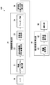
以下、本発明の実施の形態の移動体認識システムについて、図面を参照しながら説明する。図1は、本発明の実施の形態の移動体認識システムの構成を示すブロック図である。本実施の形態の移動体認識システム100は、移動体が自車両に衝突する危険度を算出してドライバに報知するシステムである。移動体認識システム100は、カメラ10、移動体検出部20、相対的進入角度推定部30、衝突危険度算出部40、及び報知部50を備えている。移動体検出部20、相対的進入角度推定部30、及び衝突危険度算出部40からなる構成は、コンピュータが本発明の実施の形態の移動体認識プログラムを実行することで実現される。移動体認識プログラムは、記憶媒体に記憶されて、記憶媒体からコンピュータによって読み出されて、コンピュータで実行されてよい。
Hereinafter, a mobile object recognition system according to an embodiment of the present invention will be described with reference to the drawings. FIG. 1 is a block diagram showing a configuration of a mobile object recognition system according to an embodiment of the present invention. The moving
まず、移動体認識システム100の概要を説明する。カメラ10は、車両に搭載され、車両が走行している間に、車両周辺を一定の周期で連続的に撮影して画像を生成し、移動体検出部20に出力する。移動体検出部20は、カメラ10から順次入力される複数の画像を用いて、それらの画像の中から移動体を検出する。自車両(即ちカメラ10)が移動しているので、地面に対して静止している物体も画像内での位置は時々刻々と変化するが、移動体検出部20は、このような複数の画像から、地面に対して移動している物体を移動体として検出する。
First, the outline of the mobile
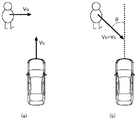
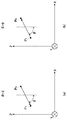
相対的進入角度推定部30は、検出された移動体の車両に対する相対的な移動方向を相対的進入角度として推定する。図2は、本発明の実施の形態における相対的進入角度を説明する図である。いま、図2(a)に示すように、車両Cが前方に速度vcで直進しており、その前方で移動体Oが車両の進行方向と直交する方向に速度voで移動しているとすると、相対的進入角度θは、図2(b)に示すように、車両の前方方向とvo−vcのなす角度として求められる。相対的進入角度推定部30は、画像とカメラ10の焦点距離を用いて、この相対的進入角度θを推定する。
The relative approach
衝突危険度算出部40は、自車両から移動体検出部20で検出された移動体までの距離を推定し、その推定された距離と、相対的進入角度推定部30で推定した相対的進入角度とに基づいて、衝突の危険度を算出する。報知部50は、衝突危険度算出部40で算出された危険度に基づいてドライバへの報知を行なう。以下、詳細に説明する。
The collision risk
カメラ10は、車両に搭載されて、車両の周辺を撮影する。特に、本実施の形態の移動体認識システム100は、移動体が自車両に対する衝突の危険性を算出して報知するので、カメラ10は、自車両の進行方向を撮影するように、車両に設置される。カメラ10は車両の前方を撮影するように、例えばルームミラーの裏側(前方側)に設置されてよい。車両は後退することも可能であるので、カメラ10が車両の後方を撮影するように、例えば後ろのナンバープレート近くに設置されてもよい。カメラ10は、一系統の光学系及び撮像素子を備えた単眼のカメラである。カメラ10は、所定の周期で(例えば1/30秒ごとに)連続的に撮像をして画像信号を出力する。
The
移動体検出部20は、直線運動を行う剛体のモデルとピンホールカメラモデルに基づいて、画像中の特徴点の座標と動きベクトル(オプティカルフロー)の情報から、同一移動体の特徴点をグルーピング(クラスタリング)する(詳細は特開2011−81613号公報を参照)。ここで、オプティカルフローとは、動画などにおいて同じ画像パッチ(例えば5ピクセル四方の小領域)を追跡した軌跡のことである。移動体検出部20は、また、オプティカルフローからカメラ10の回転移動に起因する成分を除去する処理も行なう。移動体検出部20は、連結オプティカルフロー算出部21、回転移動量・消失点推定部22、背景点除去部23、及びグルーピング部24を備えている。
The moving
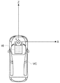
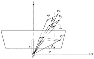
まず、以下の演算において用いる座標を定義する。図3は、本発明の実施の形態における座標の定義を説明する図である。路面が平坦なとき、カメラ10の光軸と路面は平行であると仮定する。カメラ10の光軸をZ軸、鉛直下方向をY軸とし、X軸は右手座標系により定義する。原点(0,0,0)はカメラ10の光学中心とする。なお、本実施の形態ではカメラ10の光軸を路面と平行と仮定するが、カメラ10の光軸と路面が平行でない場合においても適切な回転行列を導入することで容易に一般化が可能である。透視投影モデルを考え、画像座標は(x,y)=(fX/Z,fY/Z)で与えるものとする。ここで、fはカメラ10の焦点距離であり、既知である。
First, the coordinates used in the following calculation are defined. FIG. 3 is a diagram for explaining the definition of coordinates in the embodiment of the present invention. When the road surface is flat, it is assumed that the optical axis of the
連結オプティカルフロー算出部21は、カメラ10で得られた複数の画像から、複数の画像間で対応する特徴点を抽出し、特徴点ごとにオプティカルフローを算出する(J. shi and C. Tomasi, “Good features to track,”, IEEE CVPR, pp. 593-600, 1994を参照)。本実施の形態ではオプティカルフローの算出アルゴリズムには、LK法を使用する(B. D. Lucas and T. Kanade, “An iterative image registration technique with an application to stereo vision,” IJCAI, pp. 674-679, 1981を参照)。
The connected optical
オプティカルフローの算出においては、アウトライアが少ないことが望ましい。アウトライアとは、一般には想定外の計算結果のことを指し、オプティカルフローのアウトライアとは、特に、誤って追跡された軌跡のことを指す。上記の特許文献1の技術はオプティカルフローのアウトライアに対して頑健であるが、それでもなお稀に複数のオプティカルフローが、アウトライアであるにもかかわらず同一の消失点と外分比を許容誤差の範囲で有することがある。この場合、アウトライアを検出してしまうため、危険度の計算を誤る結果となる。本実施の形態では演算量の低い、アウトライア除去方法を提供する。
In calculating the optical flow, it is desirable that there are few outliers. The outlier generally refers to an unexpected calculation result, and the optical flow outlier particularly refers to a trajectory tracked in error. Although the technique of the above-mentioned
オプティカルフローの精度を高めるために、本実施の形態では、互いに隣り合う2つのフレーム間のオプティカルフローを使う代わりに、隣り合うフレーム間のオプティカルフローを連続する複数フレーム分連結したものを使う。本明細書では、互いに隣り合う2つのフレーム間のオプティカルフロー、即ち、あるフレームの特徴点から当該フレームの次のフレームにおける当該特徴点と同じ(対応する)特徴点へのベクトルを「単オプティカルフロー」と呼び、複数の単オプティカルフローを連結して得られたオプティカルフロー、即ち、あるフレームにおける特徴点から、そのフレームから1以上の所定のフレーム数を隔てたフレームにおける当該特徴点と同じ(対応する)特徴点へのベクトルを「連結オプティカルフロー」と呼ぶ。 In order to improve the accuracy of the optical flow, in the present embodiment, instead of using the optical flow between two adjacent frames, a concatenation of a plurality of optical flows between adjacent frames is used. In this specification, an optical flow between two adjacent frames, that is, a vector from a feature point of one frame to the same (corresponding) feature point in the next frame of the frame is referred to as “single optical flow. And the same as the feature point in the frame obtained by connecting a plurality of single optical flows, that is, the feature point in one frame at a predetermined number of frames of 1 or more from that frame (corresponding The vector to the feature point is called “connected optical flow”.
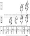
図4は、本発明の実施の形態における連結オプティカルフローを説明する図である。図4において、左の列は、カメラ10によって連続的に取得された画像を上から順に時系列に並べたものであり、中央の列は、単オプティカルフローを示しており、右の列は、3つの単オプティカルフローを連結した連結オプティカルフローを示している。連結オプティカルフロー算出部21は、同一の(対応する)特徴点の複数フレーム分の単オプティカルフローを連結し、連結オプティカルフローを算出する。
FIG. 4 is a diagram for explaining a connection optical flow in the embodiment of the present invention. In FIG. 4, the left column is a sequence in which images continuously acquired by the
図4に示すように、単オプティカルフローは、隣り合う2つのフレーム間において、同一の特徴点を結ぶことで生成され、連結オプティカルフローは複数の単オプティカルフローを連結することで生成される。図4の例では、3つ(n=3)のオプティカルフローが連結されることで、連結オプティカルフローが生成されている。 As shown in FIG. 4, a single optical flow is generated by connecting the same feature points between two adjacent frames, and a connected optical flow is generated by connecting a plurality of single optical flows. In the example of FIG. 4, a connected optical flow is generated by connecting three (n = 3) optical flows.
回転移動量・消失点推定部22は、連結オプティカルフローから消失点を推定する。一般的に、三次元上の点群が一定の速度で並進移動をするとき、これらの点群を透視投影した二次元の点群の移動の軌跡は、その延長線が一点で交わる特徴を持つ。この交点が消失点である。本明細書では、消失点という用語を、画像平面上の点の軌跡の延長線の交点の意味で用いる。なお、移動体が複数ある場合には、移動体ごとに消失点が推定される。
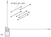
The rotational movement amount / vanishing
図5は、三次元空間の点群(移動体上の点)が単位時間内に並進移動する距離(点群の三次元空間内での速度)を示す図である。この速度Vを(ΔX,ΔY,ΔZ) とすると、時刻tにおいて透視投影された画像座標 x(t)=f(X+tΔX)/(Z+tΔZ)、y(t)=f(Y+tΔY)/(Z+tΔZ) は、t→−∞又はt→∞ の極限において、 (fΔX/ΔZ,fΔY/ΔZ) に収束する。よって、消失点の二次元座標は(fΔX/ΔZ,fΔY/ΔZ)と与えられる。なお、t→−∞で収束する点群は、カメラから遠ざかる点群であり、t→∞で収束する点群は、カメラに近づく点群である。 FIG. 5 is a diagram showing the distance (the velocity of the point group in the three-dimensional space) that the point group (point on the moving body) in the three-dimensional space moves in translation in unit time. When this velocity V is (ΔX, ΔY, ΔZ), the image coordinates x (t) = f (X + tΔX) / (Z + tΔZ) projected at time t, y (t) = f (Y + tΔY) / (Z + tΔZ) Converges to (fΔX / ΔZ, fΔY / ΔZ) in the limit of t → −∞ or t → ∞. Therefore, the two-dimensional coordinates of the vanishing point are given as (fΔX / ΔZ, fΔY / ΔZ). Note that the point cloud that converges at t → −∞ is a point cloud that moves away from the camera, and the point cloud that converges at t → ∞ is a point cloud that approaches the camera.
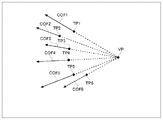
図6は、消失点を説明する図である。図6の例では、特徴点FP1〜6の連結オプティカルフローCOF1〜6の延長線が1つの点で交わっており、この点が消失点VPとなる。回転移動量・消失点推定部22は、各特徴点の連結オプティカルフローを延長して、複数の連結オプティカルフローが交わる点を探索して、それを消失点として推定する。オプティカルフローには、アウトライアや、移動体のオプティカルフローや、背景物体のオプティカルフローが混在していることを考えると、消失点の推定にはロバスト推定を適応するのが妥当である。ロバスト推定とは、はずれ値に対して頑健なパラメタ推定のことをいう。本実施の形態では、ロバスト推定として、M推定(P. J. Huber and E. M. Ronchetti, “Robust Statistice, 2nd Edition,” Wiley Interscienceを参照)を適用する。
FIG. 6 is a diagram illustrating vanishing points. In the example of FIG. 6, the extension lines of the connected optical flows COF 1 to 6 of the feature points
なお、例えば演算能力が制限されている等の理由で上述の技術を適応できない場合は、回転移動量・消失点推定部22は、以下の簡易な処理により連結オプティカルフローの消失点を求めてもよい。この方法では、回転移動量・消失点推定部22は、あらかじめカメラ10の画像の中の地平線の位置を記録しておき、地平線と連結オプティカルフローの交点を、この点の軌跡の消失点とする。この方法は、移動体とカメラ10が平らな地面と平行に移動しているとき、移動体の軌跡の消失点は地平線上に存在するという事実に基づいている。但し、連結オプティカルフローの傾きが小さい場合(地平線とほぼ平行である場合)、連結オプティカルフローの誤差が消失点の値を大きく変動させ得るので、連結オプティカルフローの誤差の範囲で消失点の値の範囲が大きすぎる場合には、例外的処理として、この点を検出候補から除外する。
If the above technique cannot be applied because, for example, the calculation capability is limited, the rotational movement amount / vanishing
また、回転移動量・消失点推定部22は、カメラ10の回転移動に起因するオプティカルフローの成分を推定して、それを連結オプティカルフローから除去する。いま、三次元の並進移動量(Vx,Vy,Vz)と回転移動量Ω=(Ωx,Ωy,Ωz)を持つカメラによって透視投影された三次元上の点(X,Y,Z)のオプティカルフローをv=(vx,vy)とすると、このオプティカルフローvは下式(1)で表される。

式(2)からpF=(xF,yF)=(fVx/Vz,fVy/Vz)と置き換えられ、奥行き成分ZとVzを消去すると、以下の式(3)が得られる。
オプティカルフローのはずれ値や移動体の点は、一般的にはRの値が大きいと考えられため、本実施の形態では、回転移動量・消失点推定部22は、式(4)のM推定を使用する。
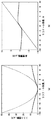
図7(a)は、ロバスト推定のコスト関数を示すグラフであり、図7(b)は、ロバスト推定の影響関数を示す図である。図7(a)及び(b)において、破線はL2ノルムを示し、実線はCauchy関数を示している。本実施の形態では、図7及び次式(5)で定義されるCauchyの影響関数を用いている。
Cauchyの影響関数は、R>0において単調増加関数ではなく、極値を境に減少に転じるため、誤差の大きな入力の解に対する影響を低く抑えることができる。式(5)の定数Cは、C=2.385である。この値は、平均を0とするガウス分布の最小二乗法の95%の効率を与えるよう設定されている。 Since the influence function of Couchy is not a monotonically increasing function at R> 0 but starts to decrease at the extreme value, the influence on the input solution having a large error can be suppressed to a low level. The constant C in equation (5) is C = 2.385. This value is set so as to give 95% efficiency of the least squares method of Gaussian distribution with an average of 0.
回転移動量・消失点推定部22は、M推定の解法として反復再重み付け最小二乗法(IRLS:Iteratively Reweighted Least Squares)を用いる。これは、式(4)のコスト関数を重み付き誤差の二乗和の形に変形し、最小二乗法と重み更新を解が収束するまで交互に繰り返す方法である。この重みは影響関数を用いて、ω=ψ(R)/Rで与えられる。以下に、IRLSのアルゴリズムを示す。
上記のステップ3)のリスケーリングにおける分母1.48mad(R)は、Rが正規分布に従うとき、標準偏差と等しくなるように設定されている。標準偏差の代わりに中央値絶対偏差(mad:median absolute deviation)を用いた理由は、アウトライアの混在によるスケールの変動を小さく抑えるためである。誤差はFOE座標と回転移動量との積の形で表されるため、ステップ4)は、非線形最小二乗法となる。本実施の形態では、回転移動量・消失点推定部22は、ニュートン法によって解を求める。回転移動量・消失点推定部22は、求めた回転移動量に起因する成分を連結オプティカルフローから除去する。
The denominator 1.48 mad (R) in the rescaling in step 3) is set to be equal to the standard deviation when R follows a normal distribution. The reason for using the median absolute deviation (mad) instead of the standard deviation is to suppress the fluctuation of the scale due to the mixture of outliers. Since the error is expressed in the form of the product of the FOE coordinates and the rotational movement amount, step 4) is a nonlinear least square method. In the present embodiment, the rotational movement amount / vanishing
背景点除去部23は、連結オプティカルフローを延長した直線が許容誤差の範囲内で背景の消失点を通る場合に、その連結オプティカルフローを背景、即ち地面に対して移動しない物体として除去する。即ち、地面に対して移動する移動体は、背景とは異なる位置に消失点を有するので、そのような消失点を有する特徴点群を移動体として検出するために、背景点除去部23は、背景の消失点を有する特徴点及びその連結オプティカルフローを除去する。
The background
次に、グルーピング部24について説明する。連結オプティカルフロー算出部21によって生成されて、回転移動量・消失点推定部22によって回転移動量に起因する成分が除去され、かつ背景除去部23によって背景として除去された後に残った連結オプティカルフローは、アウトライアか、正しくトラッキングされた移動体上の特徴点のオプティカルフローのいずれかである。グルーピング部24は、連結オプティカルフローを用いて、アウトライアを除去しつつ、特徴点及びその連結オプティカルフローのグルーピングを行なう。
Next, the
グルーピング部24は、残った特徴点とその連結オプティカルフローに対し、再度消失点をロバスト推定する。グルーピング部24は、まず、連結オプティカルフローを延長した直線が、許容誤差の範囲でこの消失点を通過する特徴点及びその連結オプティカルフローを仮のグループとしてグルーピングし、この仮のグループからアウトライアを除去し、最終的にグループを確定する。グルーピング部24は、まず、連結オプティカルフローの直進らしさによってアウトライアを判定して除去し、さらに、連結オプティカルフローより算出されるTTCの類似の度合いからアウトライアを判定して除去する。以下、順に説明する。
The
(直進らしさに基づくアウトライア除去)
特徴点が正しくトラッキングされている場合、その点が三次元空間で等速直線運動をしている限り、その軌跡は直線となる。一般に、十分に短い時間間隔で移動体の位置を観測する場合、等速直線運動モデルは良い近似である。従って、複数の単オプティカルフローが直線的に並んでいるか否かを判定することはアウトライア除去に有効である。
(Outlier removal based on straightness)
If a feature point is tracked correctly, the locus will be a straight line as long as the point moves in a uniform linear motion in a three-dimensional space. In general, the constant velocity linear motion model is a good approximation when the position of a moving object is observed at sufficiently short time intervals. Therefore, it is effective for removing outliers to determine whether or not a plurality of single optical flows are arranged linearly.
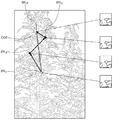
図8は、アウトライアが発生しやすい画像の例を示す図である。図8に示すように、画像の中に樹木があり、似た形状の葉や枝を多く含む画像である場合、即ち、似通ったパターンを複数個含む画像である場合は、複数のフレームについて対応する特徴点を検出すると、本来対応しない点FPt1、FPt2、FPt3、FPt4が対応する特徴点として検出されてしまう。このような特徴点及びそれらを結ぶオプティカルフローは、アウトライアである。このとき、アウトライアとして検出された特徴点FPt1、FPt2、FPt3、FPt4の連結オプティカルフローCOFを求めると、図8に示すように、連結オプティカルフローCOFと各単オプティカルフローとのずれが大きくなる。 FIG. 8 is a diagram illustrating an example of an image in which an outlier is likely to occur. As shown in Fig. 8, if there are trees in the image and the image contains many similar leaves and branches, that is, if the image contains multiple similar patterns, multiple frames are supported. When a feature point is detected, points FP t1 , FP t2 , FP t3 , and FP t4 that do not originally correspond are detected as corresponding feature points. Such feature points and the optical flow connecting them are outliers. At this time, when the coupled optical flow COF of the feature points FP t1 , FP t2 , FP t3 , and FP t4 detected as the outliers is obtained, as shown in FIG. 8, the deviation between the coupled optical flow COF and each single optical flow Becomes larger.
このようなアウトライアを判定して除去するために、グルーピング部24は、各単オプティカルフローの、連結オプティカルフローに直交する成分を抽出し、そこから直進らしさの度合いを定量化し、その値と閾値とを比較することによりアウトライアの判定を行う。具体的には、グルーピング部24は、特徴点ごとに、連結オプティカルフローを構成する各単オプティカルフローが直線的であるか否かを次の要領で判定する。
In order to determine and remove such outliers, the
いま、n連結オプティカルフローを構成する単オプティカルフローを時系列に(Vx(i), Vy(i))、i=1,2,…,nとし、n連結オプティカルフローを(Vx(1:n),Vy(1:n))と表記する。まず、グルーピング部24は、連結オプティカルフローに直交する単位ベクトルを算出する。具体的には、この単位ベクトルは(Vy(1:n),−Vx(1:n))/sqrt(Vx(1:n)2+Vy(1:n)2) と与えられる。
Now, singly optical flows constituting the n-linked optical flow are time-sequentially set (V x (i), V y (i)), i = 1, 2,..., N, and the n-linked optical flow is (V x ( 1: n) and V y (1: n)). First, the
次に、n連結オプティカルフローを構成する各単オプティカルフローとこの単位ベクトルの内積の絶対値を算出し、n個分の値の和を取り、この値を直線らしさの指標とする。グルーピング部24は、この直線らしさの指標をあらかじめ定めた閾値と比較し、連結オプティカルフローの直線らしさの指標が閾値よりも大きい特徴点及びその連結オプティカルフローを仮のグループから除外する。
Next, the absolute value of the inner product of each unit optical flow constituting the n-connected optical flow and this unit vector is calculated, the sum of n values is taken, and this value is used as a linearity index. The
(TTCの類似度に基づくアウトライア除去)
グルーピング部24は、各特徴点の連結オプティカルフローに基づいて、衝突時間(TTC:Time To Collision)を算出する。TTCとは、三次元上の点がカメラに対して接近しているとき、その点が画像平面に到達するまでの時間をいう。なお、衝突時間の算出において、画像平面は無限の広がりを持つものとする。また、点がカメラから遠ざかるときのTTCは負の値を取る。
(Outlier removal based on TTC similarity)
The
いま、連結オプティカルフローを表す二次元のベクトルをuとし、そのx成分及びy成分をそれぞれ、ux,uyとすると、u2=ux 2+uy 2を満たし、uxは、三次元座標X,Z と速度ΔX,ΔZによって下式(6)で表される。
ここで、TTCをΔTと表記すると、ΔTは、Z/(−ΔZ)で与えられる(特徴点が接近する場合は、ΔZ<0)。オプティカルフローのy成分uyについても同様の導出ができるため、下式(9)が得られる。
グルーピング部24は、各特徴点のn連結オプティカルフロー(Vx(1:n),Vy(1:n))から式(10)を用いて衝突時間ΔTn を算出する。グルーピング部24は、同一の特徴点のΔTn-1,ΔTn-2,……もΔTnと同様の方法で算出する。特徴点が正しくトラッキングされている場合には、その点が三次元空間で等速直線運動をしている限り、ΔTn,ΔTn-1,……は互いに等しくなる。上述のように、十分に短い時間間隔で移動体を観測する場合、等速直線運動モデルは良い近似であるため、ΔTn、ΔTn-1、……は互いに類似するといえる。ΔTn,ΔTn-1,……の類似が崩れている場合、それは点が誤ってトラッキングがなされた結果であり、アウトライアであると判定できる。
The
グルーピング部24は、n連結オプティカルフローを構成する特徴点群の各々について、衝突時間ΔTn、ΔTn-1、……の類似度を求めて、それを予め定めた閾値と比較し、閾値よりも小さい特徴点及びその連結オプティカルフローを仮のグループから除外する。具体的には、グルーピング部24は、TTCのずれをDj=|ΔTn-j−ΔTn|(j=1,……,n−1) と定量化し、Dj>Dthを満たすjが一つでもある場合、この特徴点及びその連結オプティカルフローをグループから除外する。ここで、Dthはあらかじめ定められた閾値である。
The
グルーピング部24は、上記の直進らしさに基づく方法、及びTTCの類似度に基づく方法によってアウトライアを除去して連結オプティカルフローのグルーピングを行なう。1つのグループにグルーピングされた複数の連結オプティカルフローの特徴点は、1つの移動体の特徴点である。グルーピング部24は、このようにして特徴点のグルーピングを行なうことで移動体を検出する。なお、グルーピング部24は、上記の直進らしさに基づく方法、及びTTCの類似度に基づく方法のいずれかのみによってアウトライアを除去してもよい。
The
次に、相対的進入角度推定部30について説明する。相対的進入角度推定部30は、移動体検出部20で検出された移動体について、その移動体の車両に対する相対的進入角度を推定する。図9は、相対的進入角度の定義を説明する図である。図9(a)は、θ<0の場合を示しており、図9(b)はθ>0の場合を示している。図9(a)及び(b)に示すように、三次元上の点がP0からP1まで移動したとき、次式(11)で与えられる角度を相対的進入角度と定義する。
図10は、相対的進入角度と消失点との関係を示す図である。同一の速度で並進移動する移動体の三次元上の複数の点Pa、Pbがあるとき、これら点の透視投影後の軌跡は消失点を持つ。いま、光学中心から消失点VPに向かうベクトルV=(fΔX/ΔZ,fΔY/ΔZ,f)を考えると、このベクトルVは、点Pa、Pbの速度ベクトルva=vb=(ΔX,ΔY,ΔZ)の定数倍(f/ΔZ倍)である。よって、光学中心から焦点距離fだけZ方向に離れたところにZ方向に垂直な画像平面を設定すると、光学中心から画像上の消失点VPに向かうベクトルVと、同一の速度で並進移動する移動体の三次元上の複数の点Pa、Pbの速度ベクトルva、vbとは、平行である。このことから、相対的進入角度は、次式(12)のとおりとなる。
次に、衝突危険度算出部40について説明する。衝突危険度算出部40は、相対的進入角度やTTCや距離推定値に基づいて移動体と自車両の衝突の危険度を算出する。衝突危険度算出部40は、距離推定部41及び危険度算出部42を備えている。距離推定部41は、自車両から移動体までのZ方向の距離(以下単に「距離」という。)を推定する。危険度算出部42は、距離推定部41にて推定された距離に基づいて、移動体が自車両に衝突する危険度を算出する。
Next, the collision
距離推定部41にて距離を推定する方法には、以下に説明する複数の方法がある。距離推定部41は以下のいずれかの一つの推定方法で距離を推定してもよいし、複数の推定方法でそれぞれ推定してもよい。推定された距離は危険度算出部42における危険度の算出に用いられるため、距離推定部41は、危険度算出部42における危険度の算出方法に必要な距離の推定を行なう。以下、それぞれ説明する。
There are a plurality of methods described below for estimating the distance by the
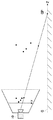
(距離推定方法の第1の例:距離の上限を算出する方法)
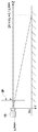
第1の例では、距離推定部41は、移動体までの距離の上限を推定する。図11は、距離推定方法の第1の例における地面点を説明する図である。また、図12は、距離推定方法の第1の例における距離の上限値の算出を説明する図である。距離推定部41は、図11に示すように、グルーピングされた特徴点群から、y座標の値が最も大きい特徴点(以下、「最下特徴点」という。)を選び、最下特徴点と光学中心を結ぶ直線と地面Gの交点(以下、「地面点」という。)GPの座標を算出する。
(First example of distance estimation method: method of calculating the upper limit of distance)
In the first example, the
図11に示すように、移動体上の点として検出された特徴点群は、それが地面よりも上にある限り、最下特徴点の指し示す三次元上の点のZ座標は、地面点GPのZ座標よりも小さくなる。グルーピングされた特徴点群の特徴点同士の間の距離が、カメラ10からの距離と比べて十分に小さいと仮定すると、地面点GPのZ座標は、特徴点群のZ座標の上限値とみなすことができる。地面点GPのZ座標、即ち距離の上限値D1は、図12に示すように、D1=Hc*f/y_maxによって与えられる。ここで、Hcはカメラ10の地面からの高さ、y_maxは最下特徴点のy座標、fは焦点距離、即ちカメラの光学中心から画像平面IPまでの距離である。なお、この方法は、y_maxが正の時のみ適応可能である。距離推定部41は、Hc*f/y_maxを距離の上限値D1として算出する。
As shown in FIG. 11, as long as the feature point group detected as a point on the moving body is above the ground, the Z coordinate of the three-dimensional point indicated by the lowest feature point is the ground point GP. Smaller than the Z coordinate. Assuming that the distance between the feature points of the grouped feature point group is sufficiently smaller than the distance from the
(距離推定方法の第2の例:距離を直接推定する方法)
第2の例では、距離推定部41は、移動体を代表する1つの代表点を特定して、自車両の並進移動速度と代表点の衝突時間TTCを利用して、距離を直接推定する。距離推定部41は、移動体としてグルーピングされた複数の特徴点のうちのいずれかを代表点として選択する。代表点として選択された特徴点のTTCは移動体検出部20で求まっているので、これを利用する。TTCをΔTとすると、ΔT=Z/(−ΔZ)である。移動体が自車両の進行方向に対して直交して並進移動していると仮定すると、ΔZ=−Vcである。ここで、Vcは自車両の並進移動速度であり、距離推定部41は図示しない構成によって、このVcを取得している。距離推定部41は、Z=ΔTVcによってZ、即ち自車両から移動体までの距離を推定する。
(Second example of distance estimation method: method of directly estimating distance)
In the second example, the
(距離推定方法の第3の例:距離の確率分布を決定する方法)
第3の例では、距離推定部41は、移動体を代表する1つの代表点を特定して、代表点の衝突時間TTCを利用して距離の確率の分布を決定する。距離推定部41は、移動体としてグルーピングされた複数の特徴点のうちのいずれかを代表点として選択する。代表点として選択された特徴点のTTCは移動体検出部20で求まっているので、これを利用する。第3の例において、距離推定部41は、移動体のZ方向の速度の確率分布を仮定する。背景点の相対的進入角度とは異なる相対的進入角度を持って移動する物体は、自車両の並進移動方向に対し非零の角度を持っている。そして、これらの移動体のZ方向の速度の確率分布を、平均0の正規分布と置くことは経験的に妥当である。
(Third example of distance estimation method: method of determining probability distribution of distance)
In the third example, the
距離推定部41は、移動体の代表点のZ方向の速度ΔZの平均−Vを予め記憶しており、その標準偏差σも、例えば3km/hとして予め固定値を記憶している。移動体の代表点のZ方向の速度ΔZの確率の分布は、平均−V、標準偏差σの正規分布に従う。代表点のTTCをΔTと表記すると、代表点の距離はZ=ΔT(−ΔZ)であり、従って、代表点の距離Zの確率分布は、平均ΔT(−V)、標準偏差ΔTσの正規分布に従うことになる。距離推定部41は、代表点の距離Zの確率分布を、平均ΔT(−V)、標準偏差ΔTσの正規分布として決定する。
The
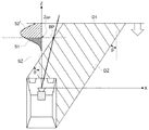
危険度算出部42は、相対的進入角度推定部30で推定された相対的進入角度θに基づいて危険ゾーンを定義した上で、移動体が自車両に衝突する危険度を算出する。危険ゾーンとは、XZ平面の中の領域であり、ある一定の相対的進入角度を持ってXZ平面上の点が自車両に接近したときに、その点が車両に衝突する範囲をいう。但し、自車両が占めるXZ平面の部分は非危険ゾーンとする。危険度算出部42は、距離推定部41における距離の推定方法に応じた方法で危険度を算出する。以下、順に説明する。
The risk
(危険度算出の第1の例:距離の上限の推定値に基づく危険度の算出)
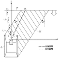
図13は、距離の上限の推定値に基づく危険度の算出を説明するための図である。危険ゾーンDZは、車両Cの進行方向(Z軸方向)から相対的進入角度θだけ傾いた方向に、当該方向に垂直な方向の車両Cの幅で延び、推定された距離の上限D1より車両Cに近い領域である。なお、危険度算出部42は、移動体が車両Cの右側にあるときには、右に相対的進入角度θだけ傾いた危険ゾーンを設定し、移動体が車両Cの左側にあるときには、左に相対的進入角度θだけ傾いた危険ゾーンを設定する。また、光学中心と画像上のある点とを通る直線をXZ平面に正射影したものを、XZレイと呼ぶこととする。換言すれば、XZレイは、傾きがX/Z=x/fで与えられる、原点を通る直線である。図13には、XZレイ(1)とXZレイ(2)が示されている。
(First example of risk level calculation: risk level calculation based on estimated upper limit of distance)
FIG. 13 is a diagram for explaining the calculation of the degree of risk based on the estimated upper limit of distance. The danger zone DZ extends in the direction inclined by the relative approach angle θ from the traveling direction of the vehicle C (Z-axis direction) with the width of the vehicle C in a direction perpendicular to the direction, and the vehicle is determined from the estimated upper limit D1 of the distance. This is a region close to C. The risk
危険度算出部42は、移動体を代表する1つの代表点を特定して、当該代表点のXZ例と危険ゾーンDZを用いて、代表点が車両に衝突する危険度を算出する。具体的には、危険度算出部42は、代表点のXZレイの、原点から上限値D1までの間の線分のうち、危険ゾーンDZに入る線分の割合を算出し、この値を危険度とする。図13の例では、XZレイ(1)の危険度は、L1/(L1+L2)となり、XZレイ(2)はすべて危険ゾーンに含まれているので、その危険度は100%(最大)となる。
The risk
図13から明らかなように、本例では、XZ平面において、相対的進入角度θの方向と代表点の位置ベクトルの方向とのずれが小さいほど(一致度が高いほど)、危険度が高くなるようにする。このことは、換言すれば、画像内において、消失点と代表点が近いほど危険度が高くなることを意味する。 As is apparent from FIG. 13, in this example, in the XZ plane, the risk increases as the deviation between the direction of the relative approach angle θ and the direction of the position vector of the representative point decreases (the degree of coincidence increases). Like that. In other words, this means that the risk level increases as the vanishing point and the representative point are closer in the image.
なお、危険度算出部42は、この割合を四捨五入するなどして離散値化し、複数の段階に分けられたレベルとして危険度を算出してもよい。この場合には、割合が高いほど危険なレベルとなるようにする。
The risk
(危険度算出の第2の例:距離の推定値に基づく危険度の算出)
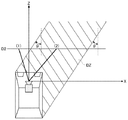
図14は、距離の推定値に基づく危険度の算出を説明するための図である。危険度算出部42は、上記の算出例と同様に、車両Cの進行方向(Z軸方向)から相対的進入角度θだけ傾いた方向に、当該方向に垂直な方向の車両Cの幅で延びる危険ゾーンDZを設定する。なお、本例でも、危険度算出部42は、移動体が車両Cの右側にあるときには、右に相対的進入角度θだけ傾いた危険ゾーンを設定し、移動体が車両Cの左側にあるときには、左に相対的進入角度θだけ傾いた危険ゾーンを設定する。但し、本例では、危険ゾーンの上限は設定しない。本例では、代表点の距離D2が推定されているので、代表点のXZレイと距離の推定値D2との交点は、即ち代表点の(X,Z)座標となる。よって、この代表点の(X,Z)座標が危険ゾーンDZに含まれるか否かを危険度とすることができる。即ち、代表点の(X,Z)座標が危険ゾーンDZに含まれているときは危険であると判定し、代表点の(X,Z)座標が危険ゾーンDZに含まれていないときは危険でないと判定する。
(Second example of risk calculation: calculation of risk based on estimated distance)
FIG. 14 is a diagram for explaining calculation of the degree of risk based on the estimated value of distance. As in the above calculation example, the risk
図14において、XZレイ(1)と距離の推定値D2との交点は、危険ゾーンDZの外にあるので、危険ではないと判定される。XZレイ(2)と距離の推定値D2との交点は、危険ゾーンDZ内にあるので、危険であると判定される。 In FIG. 14, the intersection of the XZ ray (1) and the estimated distance value D2 is outside the danger zone DZ, so it is determined that it is not dangerous. Since the intersection between the XZ ray (2) and the estimated distance value D2 is in the danger zone DZ, it is determined to be dangerous.
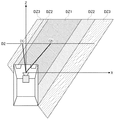
図15は、本例の変形例を説明するための図である。本変形例では、図15に示すように、危険ゾーンDZを複数のレベルに分けて段階的に設定する。この変形例では、車両Cの前方部分(フロントバンパーを含む)をより多く含む領域を危険レベルの高い危険ゾーンDZ1を設定し、その外側に危険レベルが中程度の危険ゾーンDZ2を設定し、危険ゾーンの周りにも比較的低い危険レベルの危険ゾーンDZ3を設定する。そして、危険度算出部42は、上記と同様に、XZレイと距離の推定値D2との交点が含まれる危険ゾーンに応じた危険レベルを求める。なお、このような危険ゾーンのレベル分けは、第1の例及び後述する第3及び第4の例においても行なってよい。
FIG. 15 is a diagram for explaining a modification of this example. In this modification, as shown in FIG. 15, the danger zone DZ is divided into a plurality of levels and set in stages. In this modification, a danger zone DZ1 having a high danger level is set in an area including more front parts (including the front bumper) of the vehicle C, and a danger zone DZ2 having a medium danger level is set outside thereof. A danger zone DZ3 having a relatively low danger level is also set around. Then, similarly to the above, the danger
本例でも、XZ平面において、相対的進入角度θの方向と代表点の位置ベクトルの方向とのずれが小さいほど(一致度が高いほど)、危険度が高くなるように、換言すれば、画像内において、消失点と代表点が近いほど危険度が高くなるように、危険度が算出される。 Also in this example, in the XZ plane, the smaller the deviation between the direction of the relative approach angle θ and the direction of the position vector of the representative point (the higher the degree of coincidence), the higher the degree of risk. The risk level is calculated such that the closer the vanishing point and the representative point are, the higher the risk level is.
(危険度算出の第3の例:距離の確率分布に基づく危険度の算出)
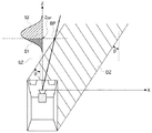
図16は、距離の確率分布に基づく危険度の算出を説明するための図である。危険度算出部42は、代表点のXZレイ上でちょうど危険ゾーンDZと安全ゾーンSZの境にある境界点BP(XBP,ZBP)を算出する。危険度算出部42は、この境界点BPのZ座標(ZBP)を境にして、距離推定部41で推定された距離の確率分布を二分する。そうすると、確率分布の全体の面積に対する危険ゾーンDZ側の確率分布の確率密度関数の積分値S1は、代表点が危険ゾーンにある確率を示し、確率分布の全体の面積に対する安全ゾーンSZ側の確率分布の確率密度関数の積分値S2は、代表点が安全ゾーンにある確率を示すこととなる。
(Third example of risk calculation: calculation of risk based on probability distribution of distance)
FIG. 16 is a diagram for explaining calculation of the degree of risk based on the probability distribution of distance. The risk
危険度算出部42は、代表点が危険ゾーンDZ側にある確率をその代表点の危険度とする。なお、距離推定部41で推定された距離分布が正規分布である場合、その積分には、誤差関数を利用できる。また、危険度算出部42は、上記のように確率をそのまま危険度としてもよいし、離散化したレベルで危険度を求めてもよい。
The risk
本例でも、XZ平面において、相対的進入角度θの方向と代表点の位置ベクトルの方向とのずれが小さいほど(一致度が高いほど)、危険度が高くなるように、換言すれば、画像内において、消失点と代表点が近いほど危険度が高くなるように、危険度が算出される。 Also in this example, in the XZ plane, the smaller the deviation between the direction of the relative approach angle θ and the direction of the position vector of the representative point (the higher the degree of coincidence), the higher the degree of risk. The risk level is calculated such that the closer the vanishing point and the representative point are, the higher the risk level is.
(危険度算出の第4の例:推定された距離の上限及び距離の分布に基づく危険度の算出)
図17は、推定された距離の上限及び距離の分布に基づく危険度の算出を説明するための図である。第4の例では、距離推定部41において、距離の上限が算出され、距離の確率分布が決定される。危険度算出部42は、距離推定部41で決定した距離の確率分布を、距離推定部41で求めた距離の上限の推定値D1で切断して単一切断正規分布とする。危険度算出部42は、距離の上限D1以下の分布を用いて、第3の例と同様に、代表点のXZレイ上で危険ゾーンDZと安全ゾーンSZの境にある境界点BP(XBP,ZBP)を算出して、この境界点BPのZ座標(ZBP)を境にして、単一切断正規分布を二分する。
(Fourth example of risk calculation: calculation of risk based on estimated upper limit of distance and distance distribution)
FIG. 17 is a diagram for explaining the calculation of the risk based on the estimated upper limit of distance and the distribution of distance. In the fourth example, the
代表点のXZレイの、距離の上限値D1までの距離範囲での確率密度関数の積分値は、即ち単一切断正規分布の積分値でありS1+S2’となり、これは一般的には100%とはならない。代表点のXZレイの、危険ゾーンにある距離範囲での確率密度関数の積分値は、図17のS1である。本例では、S1+S2’に対するS1の割合S1/(S1+S2’)をこの代表点の危険度とする。本例においても、危険度算出部42は、S1/(S1+S2’)をそのまま危険度としてもよいし、離散化したレベルで危険度を求めてもよい。
The integral value of the probability density function in the distance range up to the upper limit value D1 of the XZ ray of the representative point, that is, the integral value of the single cut normal distribution is S1 + S2 ′, which is generally 100%. Must not. The integrated value of the probability density function in the distance range in the danger zone of the representative point XZ ray is S1 in FIG. In this example, the ratio S1 / (S1 + S2 ') of S1 with respect to S1 + S2' is the risk of this representative point. Also in this example, the risk
本例でも、XZ平面において、相対的進入角度θの方向と代表点の位置ベクトルの方向とのずれが小さいほど(一致度が高いほど)、危険度が高くなるように、換言すれば、画像内において、消失点と代表点が近いほど危険度が高くなるように、危険度が算出される。 Also in this example, in the XZ plane, the smaller the deviation between the direction of the relative approach angle θ and the direction of the position vector of the representative point (the higher the degree of coincidence), the higher the degree of risk. The risk level is calculated such that the closer the vanishing point and the representative point are, the higher the risk level is.
以上説明したように、危険度算出の第1ないし第4の例のいずれにおいても、危険度は、XZ平面において、相対的進入角度θの方向と代表点の位置ベクトルの方向とのずれが小さいほど(一致度が高いほど)高くなるように、換言すれば、画像内において、消失点と代表点が近いほど高くなるように、算出される。このような例は他にもあり得る。衝突危険度算出部40は、例えば、相対的進入角度θの方向と代表点の位置ベクトルの方向との間の角度差、即ち、画像内における消失点と代表点との間の距離を危険度として算出してもよい。
As described above, in any of the first to fourth examples of risk calculation, the risk is small in the XZ plane between the direction of the relative approach angle θ and the direction of the representative point position vector. In other words, the higher the coincidence, in other words, the higher the vanishing point and the representative point in the image, the higher the calculation. There are other examples of this. The collision risk
(危険度算出の変形例)
この変形例は、上記の第1ないし第4の算出例に対して付加できる。この変形例では、上記の第1ないし第4の算出例で算出した危険度にTTCを加味して判断を行なう。TTCが小さい物体は、当然TTCが大きい物体よりも危険度が高いといえる。従って、この変形例では、TTCが小さいほど危険度が大きくなるように、上記の第1ないし第4の算出例で算出した危険度にTTCの大きさに基づく修正を加える。
(Modification of risk calculation)
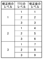
This modification can be added to the above first to fourth calculation examples. In this modification, determination is performed by adding TTC to the risk calculated in the first to fourth calculation examples. It can be said that an object with a small TTC is naturally more dangerous than an object with a large TTC. Therefore, in this modified example, the risk based on the magnitude of the TTC is added to the risk calculated in the first to fourth calculation examples so that the risk increases as the TTC decreases.
具体的には、危険度が連続値で得られている場合には、TTCの逆数をTTCレベルとして、例えば上記の第1ないし第4の算出例で算出した危険度にTTCレベルを掛けることで危険度を修正できる。また、危険度が離散的なレベルで得られている場合には、例えば図18に示すように、TTCの値を3つのレベルに分けて、危険度のレベルとTTCレベルとの組み合わせによって危険度を修正できる。 Specifically, when the risk level is obtained as a continuous value, the reciprocal of TTC is used as the TTC level, for example, by multiplying the risk level calculated in the above first to fourth calculation examples by the TTC level. The risk level can be corrected. If the risk level is obtained at discrete levels, for example, as shown in FIG. 18, the TTC value is divided into three levels, and the risk level is determined by combining the risk level and the TTC level. Can be corrected.
なお、上述のように、距離推定部41及び/又は危険度算出部42は、移動体としてグルーピングされた複数の特徴点から1点を代表点として距離の推定及び/又は危険度の算出をするが、距離推定部41及び/又は危険度算出部42は、1つの移動体について複数の代表点を特定して、それぞれの代表点について距離の推定及び/又は危険度の算出を行なって、複数の代表点いついて算出された複数の危険度の平均をとってその移動体が自車両に衝突する危険度としてもよい。また、代表点は、その移動体としてグルーピングされた複数の特徴点のうちのいずれかでなくとも、それら複数の特徴点の中点、重心点等、複数の特徴点に基づいて決定される点であってもよい。
As described above, the
報知部50は、衝突危険度算出部40にて算出された衝突の危険度に従って、ドライバに報知を行う。移動体認識システム100は、ヘッドアップディスプレイなどのディスプレイを備えている。ディスプレイには、カメラ10で撮影された画像がリアルタイムで表示される。この画像には、移動体検出部20でグルーピングされた特徴点群を囲む矩形が重畳される。このとき、報知部50は、危険度に応じて矩形の色や太さを変化させる。また、報知部50は、音によって衝突の危険をドライバに報知してもよい。この場合には、危険度が大きくなるに従って音を大きくしたり、周波数を高くしたりするなどして、ドライバの注意を喚起してよい。
The
なお、報知部50に加えて、又は報知部50に代えて、自動制動システムを設けてもよい。自動制動システムは、危険度算出部40にて算出された危険度の情報を受けて、車両の制動動作を行なう。この自動制動システムにより、危険な状況での車両の自動制動を行なうことができる。また、報知部50に加えて、又は報知部50に代えて、記憶装置を設けてもよい。記憶装置は、危険度算出部40にて算出された危険度の情報をその位置情報や時間情報とともに記憶する。この危険度の記録を参照することで、危険区域や危険時間帯を把握したり、ドライバの安全運転の状況を把握したりすることができる。
An automatic braking system may be provided in addition to or in place of the
以上のように、本発明の実施の形態の移動体認識システム100は、車両に設置されたカメラで複数の連続する単眼画像を取得して、画像中の特徴点を消失点でグルーピングすることでその画像から移動体を検出して、その画像から相対的進入角度を推定するので、相対的進入角度を用いて、その移動体が車両に衝突する危険度を算出できる。この危険度は、物理的に意味を有する指標であることから、その危険度に応じた報知をすることで、ドライバが直感的に危険な状況を知ることができ、あるいは危険な状況に応じた制御を行なうことができる。また、本発明の実施の形態の移動体認識システム100は、相対的進入角度の方向と検出された移動体の位置ベクトルの方向とのずれが小さいほど高くなるように危険度を算出するので、衝突の危険度を好適に算出できる。
As described above, the mobile
また、衝突の危険度を算出するためにステレオカメラや距離センサを用いずに比較的安価な単眼カメラを用いているので、コストを低減できる。なお、本発明の実施の形態の移動体認識システム100は、上記の構成に加えて、距離センサを併用してもよい。この場合には、移動体認識システム100は、距離センサによって得られる移動体の軌跡の情報と、上記の構成によって得られる相対的進入角度、衝突時間、移動体までの推定距離等の情報とを比較することで、検出の確からしさを強化できる。また、距離センサを併用する場合には、距離センサによって得られる移動体までの距離をも使用して、移動体の衝突の危険度の計算精度を向上させることができる。
Further, since a relatively inexpensive monocular camera is used without calculating a stereo camera or a distance sensor for calculating the risk of collision, the cost can be reduced. In addition to the above configuration, the mobile
また、移動体の検出においては、連結オプティカルフローを作成してアウトライアを除去するので、移動体の検出精度を向上できる。 Further, in detecting a moving object, since a connected optical flow is created to remove an outlier, the detection accuracy of the moving object can be improved.
本発明は、車両のドライバの安全運転のために有用な情報として、移動体が車両に衝突する危険度を得ることができるという効果を有し、単視点画像を用いて移動体を認識する移動体認識システム等として有用である。 INDUSTRIAL APPLICABILITY The present invention has an effect that a risk that a moving body collides with the vehicle can be obtained as useful information for safe driving of a vehicle driver, and movement that recognizes the moving body using a single viewpoint image This is useful as a body recognition system.
100 移動体認識システム
10 カメラ
20 移動体検出部
21 連結オプティカルフロー算出部
22 回転移動量・消失点推定部
23 背景点除去部
24 グルーピング部
30 相対的進入角度推定部
40 衝突危険度算出部
41 距離推定部
42 危険度算出部
50 報知部
DESCRIPTION OF
Claims (19)
前記カメラにて撮影された複数の画像を用いて、画像中の移動体を検出する移動体検出部と、
前記移動体検出部にて検出された移動体の前記カメラに対する相対的進入角度を推定する相対的進入角度推定部と、
前記相対的進入角度と、前記カメラから前記移動体に向かう移動体方向との関係に基づいて、前記移動体が前記車両に衝突する危険度を算出する衝突危険度算出部と、
を備え、
前記衝突危険度算出部は、前記相対的進入角度に基づいて危険ゾーンを設定し、前記移動体が危険ゾーンに存在する確率に基づいて前記危険度を算出することを特徴とする移動体認識システム。 A camera that is installed in a vehicle and shoots a plurality of continuous single viewpoint images;
Using a plurality of images taken by the camera, a moving body detection unit that detects a moving body in the image,
A relative approach angle estimation unit that estimates a relative approach angle of the mobile body detected by the mobile body detection unit to the camera;
A collision risk calculation unit that calculates a risk that the moving body collides with the vehicle based on a relationship between the relative approach angle and a moving body direction from the camera toward the moving body;
With
The collision risk calculation unit sets a danger zone based on the relative approach angle, and calculates the risk based on a probability that the moving object exists in the danger zone. .
前記距離推定部は、グルーピングされた前記移動体上の複数の特徴点から、高さが最も低い最下特徴点を選出し、前記最下特徴点と前記光学中心とを結ぶ直線と前記車両が走行する地面との交点を地面点として、前記地面点のZ座標を前記カメラから前記移動体までの前記Z方向の距離の上限値として推定する
ことを特徴とする請求項4に記載の移動体認識システム。 The moving object detection unit extracts a plurality of feature points from the image, calculates an optical flow of the extracted feature points, and extends the optical flow among the plurality of feature points. A grouping unit that groups a plurality of feature points that converge to one vanishing point as a plurality of feature points on the moving body,
The distance estimation unit selects a lowest feature point having the lowest height from a plurality of feature points on the grouped moving body, and a vehicle connecting a straight line connecting the lowest feature point and the optical center to the vehicle. The moving body according to claim 4, wherein an intersection with the traveling ground is a ground point, and a Z coordinate of the ground point is estimated as an upper limit value of the distance in the Z direction from the camera to the moving body. Recognition system.
前記距離推定部は、前記消失点に基づいて前記移動体が前記車両に衝突するまでの衝突時間を求め、前記衝突時間と前記車両の速度に基づいて前記カメラから前記移動体までの前記Z方向の距離を推定する
ことを特徴とする請求項6に記載の移動体認識システム。 The moving object detection unit extracts a plurality of feature points from the image, calculates an optical flow of the extracted feature points, and extends the optical flow among the plurality of feature points. A grouping unit that groups a plurality of feature points that converge to one vanishing point as a plurality of feature points on the moving body,
The distance estimating unit obtains a collision time until the moving body collides with the vehicle based on the vanishing point, and the Z direction from the camera to the moving body based on the collision time and the speed of the vehicle. The mobile object recognition system according to claim 6, wherein the distance is estimated.
前記距離推定部は、前記消失点に基づいて前記移動体が前記車両に衝突するまでの衝突時間を求め、前記衝突時間に基づいて、所定の正規分布に従って前記距離の確率分布を決定する
ことを特徴とする請求項8に記載の移動体認識システム。 The moving object detection unit extracts a plurality of feature points from the image, calculates an optical flow of the extracted feature points, and extends the optical flow among the plurality of feature points. A grouping unit that groups a plurality of feature points that converge to one vanishing point as a plurality of feature points on the moving body,
The distance estimation unit obtains a collision time until the moving object collides with the vehicle based on the vanishing point, and determines a probability distribution of the distance according to a predetermined normal distribution based on the collision time. The moving body recognition system according to claim 8, wherein
前記距離推定部は、グルーピングされた前記移動体上の複数の特徴点から、高さが最も低い最下特徴点を選出し、前記最下特徴点と前記光学中心とを結ぶ直線と前記車両が走行する地面との交点を地面点として、前記地面点のZ座標を前記カメラから前記移動体までの前記Z方向の距離の上限値として推定し、前記消失点に基づいて前記移動体が前記車両に衝突するまでの衝突時間を求め、前記衝突時間に基づいて、所定の正規分布に従って前記距離の確率分布を決定する
ことを特徴とする請求項10に記載の移動体認識システム。 The moving object detection unit extracts a plurality of feature points from the image, calculates an optical flow of the extracted feature points, and extends the optical flow among the plurality of feature points. A grouping unit that groups a plurality of feature points that converge to one vanishing point as a plurality of feature points on the moving body,
The distance estimation unit selects a lowest feature point having the lowest height from a plurality of feature points on the grouped moving body, and a vehicle connecting a straight line connecting the lowest feature point and the optical center to the vehicle. The intersection point with the traveling ground is set as a ground point, the Z coordinate of the ground point is estimated as an upper limit value of the distance in the Z direction from the camera to the moving body, and the moving body is based on the vanishing point. The mobile object recognition system according to claim 10, wherein a collision time until the vehicle collides is obtained, and a probability distribution of the distance is determined according to a predetermined normal distribution based on the collision time.
前記カメラにて撮影された複数の画像を用いて、前記画像から複数の特徴点を抽出して、抽出された特徴点のオプティカルフローを生成し、前記複数の特徴点のうち、延長された前記オプティカルフローが1つの消失点に収束する複数の特徴点をグルーピングすることで、グルーピングされた前記複数の特徴点を移動体として検出する移動体検出部と、
前記移動体が前記車両に衝突する危険度を算出する衝突危険度算出部と、
を備え、
前記衝突危険度算出部は、前記画像における前記消失点との間の距離が近い前記移動体の前記危険度が、前記画像における前記消失点との間の距離が遠い前記移動体の前記危険度よりも高くなるように、前記危険度を算出することを特徴とする移動体認識システム。 A camera that is installed in a vehicle and shoots a plurality of continuous single viewpoint images;
Using a plurality of images photographed by the camera, extracting a plurality of feature points from the image, generating an optical flow of the extracted feature points, and extending the plurality of feature points A moving body detection unit that detects a plurality of grouped feature points as a moving body by grouping a plurality of feature points where the optical flow converges to one vanishing point;
A collision risk calculation unit for calculating a risk of collision of the mobile body with the vehicle;
With
The collision risk degree calculation unit is configured such that the danger level of the moving object whose distance from the vanishing point in the image is short is the risk degree of the moving object whose distance from the vanishing point in the image is long. The mobile object recognition system characterized by calculating the said risk level so that it may become higher.
車両に設置され、複数の連続する単視点の画像を撮影するカメラにて撮影された複数の画像を用いて、画像中の移動体を検出する移動体検出部、
前記移動体検出部にて検出された移動体の前記カメラに対する相対的進入角度を推定する相対的進入角度推定部、及び
前記相対的進入角度と、前記カメラから前記移動体に向かう移動体方向との関係に基づいて、前記移動体が前記車両に衝突する危険度を算出する衝突危険度算出部、
として機能させる移動体認識プログラムであって、
前記衝突危険度算出部は、前記相対的進入角度に基づいて危険ゾーンを設定し、前記移動体が危険ゾーンに存在する確率に基づいて前記危険度を算出することを特徴とする移動体認識プログラム。 Computer
A moving body detection unit that detects a moving body in an image using a plurality of images captured by a camera that is installed in a vehicle and captures a plurality of continuous single viewpoint images;
A relative approach angle estimator for estimating a relative approach angle of the mobile body detected by the mobile body detector with respect to the camera; and the relative approach angle; and a mobile body direction from the camera toward the mobile body. Based on the relationship, a collision risk calculation unit that calculates a risk that the moving body will collide with the vehicle,
A moving body recognition program that functions as
The collision risk calculation unit sets a danger zone based on the relative approach angle, and calculates the risk based on a probability that the moving object exists in the danger zone. .
車両に設置され、複数の連続する単視点の画像を撮影するカメラにて撮影された複数の画像を用いて、前記画像から複数の特徴点を抽出して、抽出された特徴点のオプティカルフローを生成し、前記複数の特徴点のうち、延長された前記オプティカルフローが1つの消失点に収束する複数の特徴点をグルーピングすることで、グルーピングされた前記複数の特徴点を移動体として検出する移動体検出部、及び
前記移動体が前記車両に衝突する危険度を算出する衝突危険度算出部であって、前記画像における前記消失点との間の距離が近い前記移動体の前記危険度が、前記画像における前記消失点との間の距離が遠い前記移動体の前記危険度よりも高くなるように、前記危険度を算出する衝突危険度算出部
として機能させることを特徴とする移動体認識プログラム。 Computer
A plurality of feature points are extracted from the images using a plurality of images that are installed in a vehicle and photographed by a camera that captures a plurality of continuous single viewpoint images, and an optical flow of the extracted feature points is obtained. Generating and grouping a plurality of feature points where the extended optical flow converges to one vanishing point among the plurality of feature points, and detecting the plurality of grouped feature points as a moving object A body detection unit, and a collision risk calculation unit that calculates a risk that the moving body collides with the vehicle, wherein the risk of the moving body that is close to the vanishing point in the image is It is made to function as a collision risk calculation unit for calculating the risk so that the distance from the vanishing point in the image is higher than the risk of the moving object that is far. Moving object recognition program.
移動体検出部が、前記カメラにて撮影された複数の画像を用いて、画像中の移動体を検出する移動体検出ステップと、
相対的進入角度推定部が、前記移動体検出ステップにて検出された移動体の前記カメラに対する相対的進入角度を推定する相対的進入角度推定ステップと、
衝突危険度算出部が、前記相対的進入角度と、前記カメラから前記移動体に向かう移動体方向との関係に基づいて、前記移動体が前記車両に衝突する危険度を算出する衝突危険度算出ステップと、
を備え、
前記衝突危険度算出ステップは、前記相対的進入角度に基づいて危険ゾーンを設定し、
前記移動体が危険ゾーンに存在する確率に基づいて前記危険度を算出することを特徴とする移動体認識方法。 A shooting step in which a camera installed in the vehicle captures a plurality of continuous single viewpoint images;
A moving body detecting unit detects a moving body in the image using a plurality of images captured by the camera, and
A relative approach angle estimation unit that estimates a relative approach angle of the mobile body detected in the mobile body detection step with respect to the camera;
A collision risk calculation unit calculates a risk of collision of the moving object against the vehicle based on a relationship between the relative approach angle and a moving object direction from the camera toward the moving object. Steps,
With
The collision risk calculation step sets a danger zone based on the relative approach angle,
The mobile object recognition method, wherein the risk is calculated based on a probability that the mobile object exists in a danger zone.
移動体検出部が、前記カメラにて撮影された複数の画像を用いて、前記画像から複数の特徴点を抽出して、抽出された特徴点のオプティカルフローを生成し、前記複数の特徴点のうち、延長された前記オプティカルフローが1つの消失点に収束する複数の特徴点をグルーピングすることで、グルーピングされた前記複数の特徴点を移動体として検出する移動体検出ステップと、
衝突危険度算出部が、前記移動体が前記車両に衝突する危険度を算出する衝突危険度算出ステップと、
を含み、
前記衝突危険度算出ステップは、前記画像における前記消失点との間の距離が近い前記移動体の前記危険度が、前記画像における前記消失点との間の距離が遠い前記移動体の前記危険度よりも高くなるように、前記危険度を算出することを特徴とする移動体認識方法。 A shooting step in which a camera installed in the vehicle captures a plurality of continuous single viewpoint images;
A moving body detection unit extracts a plurality of feature points from the image using a plurality of images taken by the camera, generates an optical flow of the extracted feature points, and extracts the plurality of feature points. Among them, a moving body detecting step of detecting the plurality of grouped feature points as a moving body by grouping a plurality of feature points where the extended optical flow converges to one vanishing point;
A collision risk calculating step in which a collision risk calculating unit calculates a risk that the moving body will collide with the vehicle;
Including
In the collision risk calculation step, the risk of the moving object having a short distance from the vanishing point in the image is the risk of the moving object having a long distance from the vanishing point in the image. The moving body recognition method, wherein the risk level is calculated so as to be higher than that.
Priority Applications (5)
| Application Number | Priority Date | Filing Date | Title |
|---|---|---|---|
| JP2012169709A JP5944781B2 (en) | 2012-07-31 | 2012-07-31 | Mobile object recognition system, mobile object recognition program, and mobile object recognition method |
| CN201210407065.9A CN103578115B (en) | 2012-07-31 | 2012-10-23 | Moving body identifying system and moving body recognition methods |
| US13/689,196 US9824586B2 (en) | 2012-07-31 | 2012-11-29 | Moving object recognition systems, moving object recognition programs, and moving object recognition methods |
| EP12194786.5A EP2693416A3 (en) | 2012-07-31 | 2012-11-29 | Moving object recognition systems, moving object recognition programs, and moving object recognition methods |
| EP15175825.7A EP2960886A1 (en) | 2012-07-31 | 2012-11-29 | Moving object recognition systems, moving object recognition programs, and moving object recognition methods |
Applications Claiming Priority (1)
| Application Number | Priority Date | Filing Date | Title |
|---|---|---|---|
| JP2012169709A JP5944781B2 (en) | 2012-07-31 | 2012-07-31 | Mobile object recognition system, mobile object recognition program, and mobile object recognition method |
Publications (2)
| Publication Number | Publication Date |
|---|---|
| JP2014029604A JP2014029604A (en) | 2014-02-13 |
| JP5944781B2 true JP5944781B2 (en) | 2016-07-05 |
Family
ID=47355839
Family Applications (1)
| Application Number | Title | Priority Date | Filing Date |
|---|---|---|---|
| JP2012169709A Expired - Fee Related JP5944781B2 (en) | 2012-07-31 | 2012-07-31 | Mobile object recognition system, mobile object recognition program, and mobile object recognition method |
Country Status (4)
| Country | Link |
|---|---|
| US (1) | US9824586B2 (en) |
| EP (2) | EP2693416A3 (en) |
| JP (1) | JP5944781B2 (en) |
| CN (1) | CN103578115B (en) |
Families Citing this family (84)
| Publication number | Priority date | Publication date | Assignee | Title |
|---|---|---|---|---|
| US20140218482A1 (en) * | 2013-02-05 | 2014-08-07 | John H. Prince | Positive Train Control Using Autonomous Systems |
| KR101480647B1 (en) * | 2013-11-15 | 2015-01-09 | 현대자동차주식회사 | Steering risk decision system for driving narrow road and method of the same |
| WO2015125022A2 (en) * | 2014-02-20 | 2015-08-27 | Mobileye Vision Technologies Ltd. | Navigation based on radar-cued visual imaging |
| US10431099B2 (en) * | 2014-02-21 | 2019-10-01 | FLIR Belgium BVBA | Collision avoidance systems and methods |
| JP6174514B2 (en) * | 2014-04-14 | 2017-08-02 | 本田技研工業株式会社 | Collision possibility determination device, driving support device, collision possibility determination method, and collision possibility determination program |
| JP2016001464A (en) | 2014-05-19 | 2016-01-07 | 株式会社リコー | Processor, processing system, processing program, and processing method |
| EP2950294B1 (en) | 2014-05-30 | 2019-05-08 | Honda Research Institute Europe GmbH | Method and vehicle with an advanced driver assistance system for risk-based traffic scene analysis |
| US10572744B2 (en) | 2014-06-03 | 2020-02-25 | Mobileye Vision Technologies Ltd. | Systems and methods for detecting an object |
| JP6340957B2 (en) * | 2014-07-02 | 2018-06-13 | 株式会社デンソー | Object detection apparatus and object detection program |
| JP6265095B2 (en) * | 2014-09-24 | 2018-01-24 | 株式会社デンソー | Object detection device |
| CN104299244B (en) * | 2014-09-26 | 2017-07-25 | 东软集团股份有限公司 | Obstacle detection method and device based on monocular camera |
| JP6532229B2 (en) * | 2014-12-18 | 2019-06-19 | 株式会社デンソーテン | Object detection apparatus, object detection system, object detection method and program |
| EP3038011B1 (en) * | 2014-12-22 | 2019-06-05 | Aptiv Technologies Limited | Method for determining the distance between an object and a motor vehicle by means of a monocular imaging device |
| JP6557973B2 (en) * | 2015-01-07 | 2019-08-14 | 株式会社リコー | MAP GENERATION DEVICE, MAP GENERATION METHOD, AND PROGRAM |
| EP3275174A1 (en) * | 2015-03-23 | 2018-01-31 | Longsand Limited | Scan face of video feed |
| KR101639722B1 (en) * | 2015-05-26 | 2016-07-15 | 주식회사 피엘케이 테크놀로지 | Correction apparatus and method for vanishing point |
| JP6607630B2 (en) * | 2015-06-30 | 2019-11-20 | Kddi株式会社 | Moving object extraction apparatus, method and program |
| JP6090381B2 (en) * | 2015-07-29 | 2017-03-08 | 横浜ゴム株式会社 | Collision prevention system |
| JP6465982B2 (en) * | 2015-08-31 | 2019-02-06 | 三菱電機株式会社 | Image processing apparatus, image processing method, and program |
| CN108028022B (en) * | 2015-09-30 | 2021-06-15 | 索尼公司 | Image processing apparatus, image processing method, and vehicle control system |
| JP6450294B2 (en) | 2015-09-30 | 2019-01-09 | 株式会社デンソーアイティーラボラトリ | Object detection apparatus, object detection method, and program |
| CN105718052B (en) * | 2016-01-18 | 2018-09-11 | 京东方科技集团股份有限公司 | A kind of indicating means and device for correcting body feeling interaction tracking failure |
| JP6752024B2 (en) * | 2016-02-12 | 2020-09-09 | 日立オートモティブシステムズ株式会社 | Image processing device |
| US10552966B2 (en) * | 2016-03-07 | 2020-02-04 | Intel Corporation | Quantification of parallax motion |
| CN107176161B (en) * | 2016-03-10 | 2021-11-23 | 松下电器(美国)知识产权公司 | Recognition result presentation device, recognition result presentation method, and autonomous moving object |
| CN107180220B (en) * | 2016-03-11 | 2023-10-31 | 松下电器(美国)知识产权公司 | Dangerous prediction method |
| CN105589464B (en) * | 2016-03-28 | 2019-02-26 | 哈尔滨工程大学 | A kind of UUV dynamic obstacle avoidance method based on Speed Obstacles method |
| EP3481661A4 (en) | 2016-07-05 | 2020-03-11 | Nauto, Inc. | System and method for automatic driver identification |
| WO2018031678A1 (en) | 2016-08-09 | 2018-02-15 | Nauto Global Limited | System and method for precision localization and mapping |
| JP6597517B2 (en) * | 2016-08-10 | 2019-10-30 | 株式会社デンソー | Target detection device |
| US9996752B2 (en) * | 2016-08-30 | 2018-06-12 | Canon Kabushiki Kaisha | Method, system and apparatus for processing an image |
| EP3513265B1 (en) * | 2016-09-14 | 2024-09-18 | Nauto, Inc. | Method for near-collision determination |
| US10733460B2 (en) | 2016-09-14 | 2020-08-04 | Nauto, Inc. | Systems and methods for safe route determination |
| EP3309721A1 (en) * | 2016-09-23 | 2018-04-18 | KPIT Technologies Ltd. | Autonomous system validation |
| DE102016218849A1 (en) | 2016-09-29 | 2018-03-29 | Conti Temic Microelectronic Gmbh | Detection and tracking of objects from images of a camera |
| DE102016218853A1 (en) | 2016-09-29 | 2018-03-29 | Conti Temic Microelectronic Gmbh | Detection and validation of objects from images of a camera |
| DE102016218852A1 (en) * | 2016-09-29 | 2018-03-29 | Conti Temic Microelectronic Gmbh | Detection of objects from images of a camera |
| JP6707654B2 (en) * | 2016-09-30 | 2020-06-10 | アジア航測株式会社 | Mobile information providing system and mobile information providing program |
| US10248872B2 (en) | 2016-10-19 | 2019-04-02 | Texas Instruments Incorporated | Estimation of time to collision in a computer vision system |
| CN110178104A (en) | 2016-11-07 | 2019-08-27 | 新自动公司 | System and method for determining driver distraction |
| CN108162858B (en) * | 2016-12-07 | 2020-05-29 | 杭州海康威视数字技术股份有限公司 | Vehicle-mounted monitoring device and method thereof |
| JP6565893B2 (en) | 2016-12-26 | 2019-08-28 | トヨタ自動車株式会社 | Driving assistance device |
| JP6551384B2 (en) * | 2016-12-26 | 2019-07-31 | トヨタ自動車株式会社 | Vehicle alert device |
| EP3364336B1 (en) * | 2017-02-20 | 2023-12-20 | Continental Autonomous Mobility Germany GmbH | A method and apparatus for estimating a range of a moving object |
| US11062174B2 (en) | 2017-02-28 | 2021-07-13 | Nec Solution Innovators, Ltd. | Mobile entity detection apparatus, mobile entity detection method, and computer-readable recording medium |
| US10522040B2 (en) * | 2017-03-03 | 2019-12-31 | Kennesaw State University Research And Service Foundation, Inc. | Real-time video analytics for traffic conflict detection and quantification |
| US10444342B2 (en) * | 2017-03-08 | 2019-10-15 | Gm Global Technology Operations Llc. | Control of host device using three-dimensional position and velocity |
| JP6666289B2 (en) | 2017-03-15 | 2020-03-13 | 株式会社東芝 | Moving object spatial information calculation apparatus and collision avoidance system |
| CN109086650B (en) * | 2017-06-14 | 2022-04-12 | 现代摩比斯株式会社 | Calibration method and calibration apparatus |
| US10453150B2 (en) | 2017-06-16 | 2019-10-22 | Nauto, Inc. | System and method for adverse vehicle event determination |
| EP3638542B1 (en) | 2017-06-16 | 2022-01-26 | Nauto, Inc. | System and method for contextualized vehicle operation determination |
| WO2018229549A2 (en) | 2017-06-16 | 2018-12-20 | Nauto Global Limited | System and method for digital environment reconstruction |
| WO2019008581A1 (en) * | 2017-07-05 | 2019-01-10 | Cortica Ltd. | Driving policies determination |
| US10304207B2 (en) | 2017-07-07 | 2019-05-28 | Samsung Electronics Co., Ltd. | System and method for optical tracking |
| US11472404B2 (en) | 2017-09-01 | 2022-10-18 | Murakami Corporation | Collision prediction device, collision prediction method, and program |
| DE102017223486A1 (en) * | 2017-12-21 | 2019-06-27 | Continental Teves Ag & Co. Ohg | Method and system for avoiding lateral collisions |
| US11392131B2 (en) | 2018-02-27 | 2022-07-19 | Nauto, Inc. | Method for determining driving policy |
| WO2019198223A1 (en) * | 2018-04-13 | 2019-10-17 | 三菱電機株式会社 | Driving assistance device |
| CN110706496A (en) * | 2018-07-10 | 2020-01-17 | 北京耘科科技有限公司 | Acoustic-based environment sensing method and system |
| US10380440B1 (en) | 2018-10-23 | 2019-08-13 | Capital One Services, Llc | Method for determining correct scanning distance using augmented reality and machine learning models |
| JP7206938B2 (en) * | 2019-01-18 | 2023-01-18 | 株式会社デンソーテン | Movement amount calculator |
| CN110148169B (en) * | 2019-03-19 | 2022-09-27 | 长安大学 | Vehicle target three-dimensional information acquisition method based on PTZ (pan/tilt/zoom) pan-tilt camera |
| US11488290B2 (en) | 2019-03-31 | 2022-11-01 | Cortica Ltd. | Hybrid representation of a media unit |
| PH12019050076A1 (en) * | 2019-05-06 | 2020-12-02 | Samsung Electronics Co Ltd | Enhancing device geolocation using 3d map data |
| JPWO2020246202A1 (en) * | 2019-06-03 | 2021-12-09 | 国立大学法人 東京大学 | Measurement system, measurement method, and measurement program |
| JP7318377B2 (en) * | 2019-07-10 | 2023-08-01 | 株式会社Soken | Object detection device |
| US11514594B2 (en) | 2019-10-30 | 2022-11-29 | Vergence Automation, Inc. | Composite imaging systems using a focal plane array with in-pixel analog storage elements |
| JP7404081B2 (en) * | 2020-01-20 | 2023-12-25 | フォルシアクラリオン・エレクトロニクス株式会社 | Obstacle detection device |
| CN113408320A (en) * | 2020-03-16 | 2021-09-17 | 上海博泰悦臻网络技术服务有限公司 | Method, electronic device, and computer storage medium for vehicle collision avoidance |
| EP3920083A1 (en) * | 2020-06-05 | 2021-12-08 | Aptiv Technologies Limited | Pointing to non-mapped objects outside a vehicle |
| JP7422029B2 (en) * | 2020-07-29 | 2024-01-25 | 本田技研工業株式会社 | Communication system, information processing device, information processing method, mobile object, method for controlling a mobile object, and program |
| CN112365706B (en) * | 2020-09-14 | 2021-11-23 | 江苏大学 | Abnormal vehicle distance identification method based on multi-source information |
| KR20220037531A (en) * | 2020-09-17 | 2022-03-25 | 현대자동차주식회사 | Vehicle and controlling method of vehicle |
| US12049116B2 (en) | 2020-09-30 | 2024-07-30 | Autobrains Technologies Ltd | Configuring an active suspension |
| KR20220060404A (en) * | 2020-11-04 | 2022-05-11 | 현대자동차주식회사 | Method and apparatus for generating test case for dynamic verification of autonomous driving system |
| CN114512027B (en) * | 2020-11-16 | 2023-07-14 | 长城汽车股份有限公司 | Anti-collision control method and device |
| JP7415892B2 (en) * | 2020-11-25 | 2024-01-17 | トヨタ自動車株式会社 | Walking support system |
| CN113012475B (en) * | 2021-03-26 | 2022-02-18 | 大连海事大学 | Autonomous collision avoidance method by evaluating ship navigation collision avoidance compliance |
| CN113954867B (en) * | 2021-09-29 | 2023-10-20 | 广州文远知行科技有限公司 | Method, device, equipment and storage medium for rapidly calculating time from object to collision |
| CN114030488B (en) * | 2022-01-11 | 2022-05-03 | 清华大学 | Method and device for realizing automatic driving decision, computer storage medium and terminal |
| CN114882699B (en) * | 2022-04-08 | 2023-07-25 | 武汉理工大学 | Road section traffic risk identification method based on conflict space-time correlation characteristics in area |
| DE102022204086A1 (en) | 2022-04-27 | 2023-11-02 | Robert Bosch Gesellschaft mit beschränkter Haftung | Method for determining a dynamic foreign object-travel corridor association |
| US20240125939A1 (en) * | 2022-10-14 | 2024-04-18 | Here Global B.V. | Vehicle mirror assembly with a movable sensor |
| CN117423093B (en) * | 2023-12-18 | 2024-03-29 | 深圳市深航华创汽车科技有限公司 | Driving detection method, device, equipment and storage medium based on driving recorder |
Family Cites Families (39)
| Publication number | Priority date | Publication date | Assignee | Title |
|---|---|---|---|---|
| US4143370A (en) * | 1972-05-20 | 1979-03-06 | Toyota Kogyo Kabushiki Kaisha | Vehicle collision anticipating method and device |
| FR2713808B1 (en) * | 1993-12-14 | 1996-01-26 | Thomson Csf | Anti-collision device, in particular for motor vehicles. |
| IL117279A (en) * | 1996-02-27 | 2000-01-31 | Israel Aircraft Ind Ltd | System for detecting obstacles on a railway track |
| JPH113499A (en) | 1997-06-10 | 1999-01-06 | Hitachi Ltd | Mobile body management system, mobile body mounting device, base station device and mobile body managing method |
| JP3986683B2 (en) * | 1998-08-25 | 2007-10-03 | 本田技研工業株式会社 | Vehicle travel safety device |
| JP2000357299A (en) * | 1999-06-16 | 2000-12-26 | Honda Motor Co Ltd | Safety device for vehicle running |
| JP4007723B2 (en) * | 1999-06-16 | 2007-11-14 | 本田技研工業株式会社 | Vehicle travel safety device |
| JP3838166B2 (en) | 2002-06-20 | 2006-10-25 | 日産自動車株式会社 | Driving assistance device for vehicle |
| JP4281485B2 (en) * | 2003-09-11 | 2009-06-17 | トヨタ自動車株式会社 | Start-up control device for collision damage mitigation device and sensor used therefor |
| JP4396400B2 (en) * | 2004-06-02 | 2010-01-13 | トヨタ自動車株式会社 | Obstacle recognition device |
| US7409295B2 (en) * | 2004-08-09 | 2008-08-05 | M/A-Com, Inc. | Imminent-collision detection system and process |
| JP4539348B2 (en) | 2004-09-07 | 2010-09-08 | 日産自動車株式会社 | Collision time calculation device and obstacle detection device |
| JP4466571B2 (en) * | 2005-05-12 | 2010-05-26 | 株式会社デンソー | Driver status detection device, in-vehicle alarm device, driving support system |
| JP4169065B2 (en) * | 2006-02-13 | 2008-10-22 | 株式会社デンソー | Vehicle control device |
| JP5003674B2 (en) * | 2006-03-27 | 2012-08-15 | 株式会社村田製作所 | Radar device and moving body |
| JP4676373B2 (en) | 2006-04-27 | 2011-04-27 | 株式会社デンソー | Peripheral recognition device, peripheral recognition method, and program |
| JP4919036B2 (en) * | 2007-01-30 | 2012-04-18 | アイシン精機株式会社 | Moving object recognition device |
| JP2008242544A (en) * | 2007-03-26 | 2008-10-09 | Hitachi Ltd | Collision avoidance device and method |
| US7865277B1 (en) * | 2007-05-07 | 2011-01-04 | The United States Of America As Represented By The Secretary Of The Navy | Obstacle avoidance system and method |
| JP5078637B2 (en) * | 2008-01-29 | 2012-11-21 | 富士通テン株式会社 | Radar apparatus and target detection method |
| US20110019873A1 (en) * | 2008-02-04 | 2011-01-27 | Konica Minolta Holdings, Inc. | Periphery monitoring device and periphery monitoring method |
| US8095313B1 (en) * | 2008-06-23 | 2012-01-10 | The United States Of America As Represented By The Secretary Of The Navy | Method for determining collision risk for collision avoidance systems |
| US8244458B1 (en) * | 2008-06-23 | 2012-08-14 | The United States Of America As Represented By The Secretary Of The Navy | Host-centric method for automobile collision avoidance decisions |
| AT507035B1 (en) * | 2008-07-15 | 2020-07-15 | Airbus Defence & Space Gmbh | SYSTEM AND METHOD FOR AVOIDING COLLISION |
| JP5345350B2 (en) * | 2008-07-30 | 2013-11-20 | 富士重工業株式会社 | Vehicle driving support device |
| ES2400708T3 (en) * | 2008-08-27 | 2013-04-11 | Saab Ab | Use of an image sensor and a time tracking filter to avoid collisions in flight |
| JP5483535B2 (en) * | 2009-08-04 | 2014-05-07 | アイシン精機株式会社 | Vehicle periphery recognition support device |
| JP5152144B2 (en) | 2009-10-07 | 2013-02-27 | 株式会社デンソーアイティーラボラトリ | Image processing device |
| JP2011118482A (en) | 2009-11-30 | 2011-06-16 | Fujitsu Ten Ltd | In-vehicle device and recognition support system |
| DE102009054835A1 (en) * | 2009-12-17 | 2011-06-22 | Robert Bosch GmbH, 70469 | object sensor |
| SE534621C2 (en) * | 2010-01-19 | 2011-10-25 | Volvo Technology Corp | Device for dead angle warning |
| DE102012103134A1 (en) * | 2011-04-12 | 2012-10-18 | Conti Temic Microelectronic Gmbh | A method of warning a driver of a vehicle of backward traffic |
| JP5435172B2 (en) * | 2011-04-20 | 2014-03-05 | トヨタ自動車株式会社 | Perimeter warning device for vehicles |
| CN102303605A (en) * | 2011-06-30 | 2012-01-04 | 中国汽车技术研究中心 | Multi-sensor information fusion-based collision and departure pre-warning device and method |
| WO2013031095A1 (en) * | 2011-08-31 | 2013-03-07 | 日産自動車株式会社 | Vehicle driving assistance device |
| WO2013046408A1 (en) * | 2011-09-29 | 2013-04-04 | トヨタ自動車株式会社 | Image display device and image display method |
| WO2013046407A1 (en) * | 2011-09-29 | 2013-04-04 | トヨタ自動車株式会社 | Image display device, and image display method |
| EP2578464B1 (en) * | 2011-10-06 | 2014-03-19 | Honda Research Institute Europe GmbH | Video-based warning system for a vehicle |
| JP5867273B2 (en) * | 2012-04-27 | 2016-02-24 | 富士通株式会社 | Approaching object detection device, approaching object detection method, and computer program for approaching object detection |
-
2012
- 2012-07-31 JP JP2012169709A patent/JP5944781B2/en not_active Expired - Fee Related
- 2012-10-23 CN CN201210407065.9A patent/CN103578115B/en active Active
- 2012-11-29 US US13/689,196 patent/US9824586B2/en active Active
- 2012-11-29 EP EP12194786.5A patent/EP2693416A3/en not_active Withdrawn
- 2012-11-29 EP EP15175825.7A patent/EP2960886A1/en not_active Withdrawn
Also Published As
| Publication number | Publication date |
|---|---|
| CN103578115A (en) | 2014-02-12 |
| EP2960886A1 (en) | 2015-12-30 |
| US9824586B2 (en) | 2017-11-21 |
| EP2693416A2 (en) | 2014-02-05 |
| EP2693416A3 (en) | 2014-11-19 |
| US20140037138A1 (en) | 2014-02-06 |
| CN103578115B (en) | 2018-09-21 |
| JP2014029604A (en) | 2014-02-13 |
Similar Documents
| Publication | Publication Date | Title |
|---|---|---|
| JP5944781B2 (en) | Mobile object recognition system, mobile object recognition program, and mobile object recognition method | |
| KR102109941B1 (en) | Method and Apparatus for Vehicle Detection Using Lidar Sensor and Camera | |
| EP3258214B1 (en) | Object detection device | |
| JP6151150B2 (en) | Object detection device and vehicle using the same | |
| US10650271B2 (en) | Image processing apparatus, imaging device, moving object device control system, and image processing method | |
| JP6450294B2 (en) | Object detection apparatus, object detection method, and program | |
| US20050232463A1 (en) | Method and apparatus for detecting a presence prior to collision | |
| JP6328327B2 (en) | Image processing apparatus and image processing method | |
| JP5482672B2 (en) | Moving object detection device | |
| JP6769477B2 (en) | Image processing device, imaging device, mobile device control system, image processing method, and program | |
| KR102569437B1 (en) | Apparatus and method tracking object based on 3 dimension images | |
| JP6816401B2 (en) | Image processing device, imaging device, mobile device control system, image processing method, and program | |
| JP2014106901A (en) | Distance calculation device, collision detection system, distance calculation method, collision detection method, and program | |
| KR101427032B1 (en) | Apparatus and method for recognizing pedestrian in vehicle, and apparatus and method for warning and preventing collision with pedestrian in vehicle using thereof | |
| JP2010079582A (en) | Apparatus, method and program for detecting object | |
| JP2017207874A (en) | Image processing apparatus, imaging apparatus, moving body device control system, image processing method, and program | |
| EP4009228A1 (en) | Method for determining a semantic free space | |
| JP2017207881A (en) | Image processing apparatus, imaging apparatus, moving body device control system, image processing method, and program | |
| JP6812701B2 (en) | Image processing equipment, mobile device control system, image processing method, and program | |
| JP5655038B2 (en) | Mobile object recognition system, mobile object recognition program, and mobile object recognition method | |
| JP2013069045A (en) | Image recognition device, image recognition method, and image recognition program | |
| Frémont et al. | Visual confirmation of mobile objects tracked by a multi-layer lidar | |
| JP2017211791A (en) | Image processing device, imaging device, mobile body equipment control system, image processing method, and program | |
| JP2019160251A (en) | Image processing device, object recognition device, instrument control system, moving body, image processing method and program | |
| Petersson et al. | Smart Cars: The Next Frontier |
Legal Events
| Date | Code | Title | Description |
|---|---|---|---|
| A621 | Written request for application examination |
Free format text: JAPANESE INTERMEDIATE CODE: A621 Effective date: 20141017 |
|
| A131 | Notification of reasons for refusal |
Free format text: JAPANESE INTERMEDIATE CODE: A131 Effective date: 20150623 |
|
| A977 | Report on retrieval |
Free format text: JAPANESE INTERMEDIATE CODE: A971007 Effective date: 20150625 |
|
| A521 | Request for written amendment filed |
Free format text: JAPANESE INTERMEDIATE CODE: A523 Effective date: 20150730 |
|
| RD04 | Notification of resignation of power of attorney |
Free format text: JAPANESE INTERMEDIATE CODE: A7424 Effective date: 20151113 |
|
| A02 | Decision of refusal |
Free format text: JAPANESE INTERMEDIATE CODE: A02 Effective date: 20160105 |
|
| A521 | Request for written amendment filed |
Free format text: JAPANESE INTERMEDIATE CODE: A523 Effective date: 20160226 |
|
| A521 | Request for written amendment filed |
Free format text: JAPANESE INTERMEDIATE CODE: A523 Effective date: 20160325 |
|
| A911 | Transfer to examiner for re-examination before appeal (zenchi) |
Free format text: JAPANESE INTERMEDIATE CODE: A911 Effective date: 20160414 |
|
| TRDD | Decision of grant or rejection written | ||
| A01 | Written decision to grant a patent or to grant a registration (utility model) |
Free format text: JAPANESE INTERMEDIATE CODE: A01 Effective date: 20160517 |
|
| A61 | First payment of annual fees (during grant procedure) |
Free format text: JAPANESE INTERMEDIATE CODE: A61 Effective date: 20160526 |
|
| R150 | Certificate of patent or registration of utility model |
Ref document number: 5944781 Country of ref document: JP Free format text: JAPANESE INTERMEDIATE CODE: R150 |
|
| R250 | Receipt of annual fees |
Free format text: JAPANESE INTERMEDIATE CODE: R250 |
|
| R250 | Receipt of annual fees |
Free format text: JAPANESE INTERMEDIATE CODE: R250 |
|
| R250 | Receipt of annual fees |
Free format text: JAPANESE INTERMEDIATE CODE: R250 |
|
| LAPS | Cancellation because of no payment of annual fees |