JP2014106901A - Distance calculation device, collision detection system, distance calculation method, collision detection method, and program - Google Patents
Distance calculation device, collision detection system, distance calculation method, collision detection method, and program Download PDFInfo
- Publication number
- JP2014106901A JP2014106901A JP2012261529A JP2012261529A JP2014106901A JP 2014106901 A JP2014106901 A JP 2014106901A JP 2012261529 A JP2012261529 A JP 2012261529A JP 2012261529 A JP2012261529 A JP 2012261529A JP 2014106901 A JP2014106901 A JP 2014106901A
- Authority
- JP
- Japan
- Prior art keywords
- distance
- vehicle
- obstacle
- image
- calculating
- Prior art date
- Legal status (The legal status is an assumption and is not a legal conclusion. Google has not performed a legal analysis and makes no representation as to the accuracy of the status listed.)
- Pending
Links
Images

Landscapes
- Traffic Control Systems (AREA)
- Image Analysis (AREA)
Abstract
【課題】自車と障害物が衝突する可能性があるか否かを精度よく判定する。
【解決手段】画像に写る障害物の位置を示すフレームと、当該障害物についてのオプティカルフローの消失点との距離に基づいて、自車両に対する障害物の相対移動方向に直交する方向についての、自車両と障害物との距離を算出する(ステップS108,S110,S112,S113)。そして、自車両と障害物との距離と、撮影装置と自車両の側面までの距離とを比較することにより、自車両と障害物とが衝突するか否かを判定する(ステップS114)。
【選択図】図6An object of the present invention is to accurately determine whether or not there is a possibility of collision between an own vehicle and an obstacle.
According to a distance between a frame indicating the position of an obstacle in an image and a vanishing point of an optical flow with respect to the obstacle, the vehicle in a direction orthogonal to the relative movement direction of the obstacle with respect to the own vehicle. The distance between the vehicle and the obstacle is calculated (steps S108, S110, S112, S113). Then, it is determined whether or not the host vehicle and the obstacle collide by comparing the distance between the host vehicle and the obstacle and the distance between the photographing apparatus and the side surface of the host vehicle (step S114).
[Selection] Figure 6
Description
本発明は、距離算出装置、衝突検出システム、距離算出方法、衝突検出方法、及びプログラムに関し、更に詳しくは、車両と障害物との距離を算出するための距離算出装置、距離算出方法及びプログラム、並びに車両と障害物との衝突を検出するための衝突検出システム及び衝突検出方法及びプログラムに関する。 The present invention relates to a distance calculation device, a collision detection system, a distance calculation method, a collision detection method, and a program, and more particularly, a distance calculation device, a distance calculation method, and a program for calculating a distance between a vehicle and an obstacle, The present invention also relates to a collision detection system, a collision detection method, and a program for detecting a collision between a vehicle and an obstacle.
近年、自車の進行方向を撮影するカメラからの画像を用いて、自車に接近する車両を検出する運転支援システムの実用化が進められている(例えば特許文献1乃至3参照)。 In recent years, a driving assistance system that detects a vehicle approaching the host vehicle using an image from a camera that captures the traveling direction of the host vehicle has been put into practical use (see, for example, Patent Documents 1 to 3).
特許文献1に記載された装置は、ステレオカメラを用いて車両前方の障害物の検出を試みる。そして、障害物に衝突するまでの衝突予測時間と閾値との比較結果に基づいて、自車のスロットル及びブレーキを制御する。 The apparatus described in Patent Document 1 attempts to detect an obstacle ahead of the vehicle using a stereo camera. Then, the throttle and brake of the host vehicle are controlled based on the comparison result between the predicted collision time until the vehicle collides with the obstacle and the threshold value.
特許文献2に記載された装置は、単眼カメラに写る障害物の大きさの変化から、衝突予測時間を算出する。そして、算出した衝突予測時間に応じて、ブレーキの制御を行う。
The apparatus described in
特許文献3に記載された装置は、画像に写る障害物のエッジの位置や大きさの変化に基づいて、自車の前方に位置する障害物を検出する。 The device described in Patent Document 3 detects an obstacle located in front of the host vehicle based on a change in the position and size of the edge of the obstacle appearing in the image.
上述した装置を用いることで、自車の進行方向に位置する障害物が検出された場合に、車両の速度を減速させたり、衝突の危険性をドライバに報知することが可能となる。 By using the above-described device, when an obstacle located in the traveling direction of the host vehicle is detected, the speed of the vehicle can be reduced or the danger of a collision can be notified to the driver.
しかしながら、ドライバにストレスを与えることなく運転を支援するためには、自車両の進行方向に位置する障害物を画一的に検出するだけではなく、障害物が自車に衝突する可能性を判定する必要がある。 However, in order to support driving without stressing the driver, not only the obstacles located in the traveling direction of the host vehicle are detected uniformly, but also the possibility that the obstacle collides with the host vehicle is determined. There is a need to.
本発明は、上述の事情の下になされたもので、自車と障害物が衝突する可能性があるか否かを精度よく判定することを目的とする。 The present invention has been made under the above-described circumstances, and an object thereof is to accurately determine whether or not there is a possibility of collision between the own vehicle and an obstacle.
上記目的を達成するために、本発明の第1の観点に係る距離算出装置は、
車両の進行方向を順次撮影する撮影手段と、
前記撮影手段によって撮影された第1画像に写る障害物の特徴点を始点とし、前記第1画像が撮影された後に撮影された第2画像に写る障害物の特徴点を終点とする複数のオプティカルフローを算出するオプティカルフロー算出手段と、
前記車両に対して前記障害物が移動する第1方向に直交する第2方向についての、前記オプティカルフローの消失点と前記画像に写る障害物との第1距離に基づいて、前記車両と前記障害物との前記第2方向についての第2距離を算出する距離算出手段と、
を備える。
In order to achieve the above object, a distance calculation apparatus according to the first aspect of the present invention provides:
Photographing means for sequentially photographing the traveling direction of the vehicle;
A plurality of optical elements starting from a feature point of an obstacle appearing in the first image taken by the photographing means and ending at a feature point of the obstacle appearing in a second image taken after the first image is taken An optical flow calculating means for calculating the flow;
Based on the first distance between the vanishing point of the optical flow and the obstacle appearing in the image in a second direction orthogonal to the first direction in which the obstacle moves relative to the vehicle, the vehicle and the obstacle Distance calculating means for calculating a second distance with respect to the object in the second direction;
Is provided.
本発明の第2の観点に係る衝突検出システムは、
本発明の第1の観点に係る距離算出装置と、
前記距離算出装置によって算出された第2距離に基づいて、前記車両と前記障害物とが衝突するか否かを判定する判定手段と、
を備える。
A collision detection system according to a second aspect of the present invention includes:
A distance calculation device according to a first aspect of the present invention;
Determining means for determining whether or not the vehicle and the obstacle collide based on the second distance calculated by the distance calculating device;
Is provided.
本発明の第3の観点に係る距離算出方法は、
車両の進行方向を順次撮影する工程と、
撮影された第1画像に写る障害物の特徴点を始点とし、前記第1画像が撮影された後に撮影された第2画像に写る障害物の特徴点を終点とする複数のオプティカルフローを算出する工程と、
前記車両に対して前記障害物が移動する第1方向に直交する第2方向についての、前記オプティカルフローの消失点と前記画像に写る障害物との第1距離を求める工程と、
前記車両と前記障害物との前記第2方向についての第2距離を算出する工程と、
を含む。
The distance calculation method according to the third aspect of the present invention is:
A step of sequentially photographing the traveling direction of the vehicle;
A plurality of optical flows starting from the feature points of the obstacle appearing in the first image taken and starting from the feature points of the obstacle appearing in the second image taken after the first image is taken are calculated. Process,
Obtaining a first distance between the vanishing point of the optical flow and the obstacle reflected in the image in a second direction orthogonal to the first direction in which the obstacle moves relative to the vehicle;
Calculating a second distance between the vehicle and the obstacle in the second direction;
including.
本発明の第4の観点に係る衝突検出方法は、
本発明の第3の観点に係る距離算出方法によって算出された第2距離に基づいて、前記車両と前記障害物とが衝突するか否かを判定する工程を含む。
A collision detection method according to a fourth aspect of the present invention includes:
A step of determining whether or not the vehicle and the obstacle collide based on the second distance calculated by the distance calculation method according to the third aspect of the present invention.
本発明の第5の観点に係るプログラムは、
コンピュータに、
車両の前方を撮影することにより得られた第1画像に写る障害物の特徴点を始点とし、前記第1画像が撮影された後に、前記車両の前方を撮影することにより得られた第2画像に写る障害物の特徴点を終点とする複数のオプティカルフローを算出する手順と、
前記車両に対して前記障害物が移動する第1方向に直交する第2方向についての、前記オプティカルフローの消失点と前記画像に写る障害物との第1距離を求める手順と、
前記車両と前記障害物との前記第2方向についての第2距離を算出する手順と、
を実行させる。
A program according to the fifth aspect of the present invention is:
On the computer,
A second image obtained by photographing the front of the vehicle after the first image is photographed, starting from the feature point of the obstacle in the first image obtained by photographing the front of the vehicle. A procedure for calculating a plurality of optical flows whose end points are feature points of obstacles appearing in
A procedure for obtaining a first distance between a vanishing point of the optical flow and an obstacle reflected in the image in a second direction orthogonal to a first direction in which the obstacle moves with respect to the vehicle;
Calculating a second distance between the vehicle and the obstacle in the second direction;
Is executed.
本発明によれば、車両に対して障害物が移動する第1方向に直交する第2方向についての、車両と障害物との距離を算出することができる。このため、自車両と障害物が衝突するか否かを精度よく判定することが可能となる。 ADVANTAGE OF THE INVENTION According to this invention, the distance of a vehicle and an obstruction can be calculated about the 2nd direction orthogonal to the 1st direction where an obstruction moves with respect to a vehicle. For this reason, it becomes possible to determine accurately whether the own vehicle and an obstacle collide.
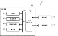
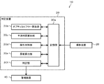
以下、本発明の一実施形態を、図面を参照しつつ説明する。図1は本実施形態に係る衝突判定システム10の構成を示すブロック図である。衝突判定システム10は、自車に接近し衝突する可能性がある物体を検出するためのシステムである。この衝突判定システム10は、図1に示されるように、撮影装置20、判定装置30、及び警報装置40を有している。
Hereinafter, an embodiment of the present invention will be described with reference to the drawings. FIG. 1 is a block diagram showing a configuration of a
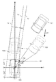
撮影装置20は、被写体を所定のフレームレートで撮影するCCDカメラである。そして、撮影により取得した画像を電気信号に変換し、画像情報として出力する。撮影装置20は、例えば図2に示されるように、車両100のフロントウインド上部に取り付けられている。
The photographing
図3は、車両100と、当該車両100の前方を走行する車両101との相対的な位置関係を示す図である。例えば、車両100の前方を走行する車両101が、車両100に相対的に接近している場合を考える。図3を参照するとわかるように、矢印a1に示される位置にある車両101は、所定の時間が経過すると矢印a2に示される位置に相対的に移動する。この場合には、撮影装置20によって、まず矢印a1に示される位置にある車両101が撮影され、次に矢印a2に示される位置にある車両101が撮影される。
FIG. 3 is a diagram illustrating a relative positional relationship between the
図4は、図3における矢印a1に示される位置にある車両101を撮影することにより得られた画像PH1を示す図である。また、図5は、図3における矢印a2に示される位置にある車両101を撮影することにより得られた画像PH2を示す図である。図4及び図5を参照するとわかるように車両100に車両101が相対的に接近する場合には、画像に写る車両101は、フレーム毎に大きくなる。
FIG. 4 is a diagram showing an image PH1 obtained by photographing the
本実施形態では、上述の画像PH1,PH2などの画像について、xy座標系を定義する。このxy座標系は、撮影装置20の光学中心に対応する点(撮影装置20の光軸とその画像面との交点である画像中心)を原点Xc(FOE:Focus of Expansion)とする。このxy座標系の原点Xcは、画像PH1,PH2の中心と一致している。
In the present embodiment, an xy coordinate system is defined for images such as the above-described images PH1 and PH2. In this xy coordinate system, a point corresponding to the optical center of the photographing apparatus 20 (image center that is the intersection of the optical axis of the photographing
図1に戻り、判定装置30は、CPU(Central Processing Unit)31、主記憶部32、補助記憶部33、表示部34、及びインタフェース部35を有するコンピュータである。
Returning to FIG. 1, the
CPU31は、補助記憶部33に記憶されているプログラムに従って、車両100へ衝突する可能性のある車両や、ガードレールなどの障害物を検出する。具体的な処理の内容については後述する。
The
主記憶部32は、RAM(Random Access Memory)等を有している。主記憶部32は、CPU31の作業領域として用いられる。
The
補助記憶部33は、例えばROM(Read Only Memory)、半導体メモリ等の不揮発性メモリを有している。補助記憶部33は、CPU31が実行するプログラム、及び各種パラメータなどを記憶している。また、撮影装置20から出力される画像情報、及びCPU31による処理結果などを含む情報を順次記憶する。
The
表示部34は、LCD(Liquid Crystal Display)などの表示ユニットを有している。表示部34は、CPU31の処理結果などを表示する。
The
インタフェース部35は、シリアルインタフェースまたはLAN(Local Area Network)インタフェースなどを含んで構成されている。撮影装置20及び警報装置40は、インタフェース部35を介してシステムバス36に接続される。
The
警報装置40は、判定装置30から出力される警報発令指示を受信すると、車両100のドライバに対して、例えば音声による警報を出力する。
When the
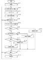
図6のフローチャートは、CPU31によって実行されるプログラムの一連の処理アルゴリズムに対応している。以下、図6を参照しつつ、衝突判定システム10の動作について説明する。図6に示される一連の処理は、車両100のドライバによってイグニッションスイッチがオンにされることによって実行される。
The flowchart in FIG. 6 corresponds to a series of processing algorithms of a program executed by the
最初のステップS101では、CPU31の衝突判定システム10の起動直後の初期化処理として、不図示のタイマ、フラグ、パラメータ、変数等の初期化を行う。
In the first step S101, timers (not shown), flags, parameters, variables, and the like are initialized as initialization processing immediately after activation of the
次のステップS102では、最も新しい1組の画像PHから、オプティカルフローを算出する。 In the next step S102, an optical flow is calculated from the newest set of images PH.
具体的には、CPU31は、画像PH1,画像PH2を構成する画素についての特徴量を算出する。例えば、図4に示される画像PH1を構成する画素M(x、y)それぞれの特徴量f(x、y)は、画像の輝度勾配を示す関数I(x、y)を用いると次式(1)によって表される。
Specifically, the
![]()
![]()
ただし、Ixx、Iyy、Ixyはそれぞれ次式(2)〜(4)によってそれぞれ表される。また、kは定数である。 However, Ixx, Iyy, and Ixy are respectively expressed by the following equations (2) to (4). K is a constant.
CPU31は、まず、式(1)を用いて画像PH1を構成する画素M(x、y)についての特徴量f(x、y)を算出する。そして、CPU31は、画素M(x、y)の周囲にある画素の輝度の平均値AVG(x、y)を算出し、特徴量f(x、y)を、輝度の平均値AVG(x、y)を4乗したもので除する。CPU31は、これにより得られた比較値V(=f(x、y)/AVG(x、y)4)を、予め設定された閾値と比較して、比較値Vが閾値以上の場合に、このときの画素M(x、y)を特徴点として抽出する。
First, the
これにより、図4に示されるように、画像PH1から特徴点P1〜P4が抽出される。CPU31は、画像PH2に対しても同様の処理を施す。これにより、図5に示されるように、画像PH2から特徴点Q1〜Q4が抽出される。なお、ここでは説明の便宜上、各画像から、特徴点が4つ抽出される場合について述べたが、実際は、1枚の画像から複数の特徴点が抽出される。
Thereby, as shown in FIG. 4, feature points P1 to P4 are extracted from the image PH1. The
画像PH1,PH2から特徴点を抽出すると、CPU31は、画像PH1の特徴点を始点とし、画像PH2の特徴点を終点とするオプティカルフローを規定する。
When the feature points are extracted from the images PH1 and PH2, the
例えば、画像PH1の特徴点P1は、画像PH2の特徴点Q1に対応する。また、画像PH1の特徴点P2は、画像PH2の特徴点Q2に対応する。また、画像PH1の特徴点P3は、画像PH2の特徴点Q3に対応する。また、画像PH1の特徴点P4は、画像PH2の特徴点Q4に対応する。 For example, the feature point P1 of the image PH1 corresponds to the feature point Q1 of the image PH2. The feature point P2 of the image PH1 corresponds to the feature point Q2 of the image PH2. The feature point P3 of the image PH1 corresponds to the feature point Q3 of the image PH2. The feature point P4 of the image PH1 corresponds to the feature point Q4 of the image PH2.
そこで、CPU31は、図7に示されるように、xy座標系に、特徴点P1を始点とし、特徴点Q1を終点とするオプティカルフローOP1を規定する。同様に、特徴点P2,P3,P4をそれぞれ始点として、特徴点Q2,Q3,Q4をそれぞれ終点とするオプティカルフローOP2,OP3,OP4をそれぞれ規定する。
Therefore, as shown in FIG. 7, the
図7に示されるように、本実施形態では説明の便宜上、車両101に関するオプティカルフローが4本である場合について説明している。しかしながら、実際は、車両101を撮影した画像からは、数十或いは数百の特徴点が抽出され、数十或いは数百本のオプティカルフローが規定される。
As shown in FIG. 7, in the present embodiment, for convenience of explanation, a case where there are four optical flows related to the
図6に戻り、次のステップS103では、CPU31は、数十或いは数百本のオプティカルフローのうちから、ノイズ成分を多く含むオプティカルフローを除外し、残りのオプティカルフローをグルーピングする。
Returning to FIG. 6, in the next step S <b> 103, the
例えば、車両101が完全な直線運動をしている場合には、各オプティカルフローと一致する直線それぞれは、消失点VPで交わるはずである。そこで、CPU31は、オプティカルフローと一致する直線が、消失点VPから著しく離れている場合に、このオプティカルフローを除外し、残りのオプティカルフローを同一の移動体に関連するオプティカルフローとみなしてグルーピングする。ここでは車両101に関するオプティカルフローOP1〜OP4が、車両101のオプティカルフローとしてグルーピングされる。
For example, when the
次のステップS104では、CPU31は、オプティカルフローを用いて、障害物が車両100に衝突するまでの衝突予測時間TTCを算出する。衝突予測時間TTCを算出する際には、障害物が車両100に対してZ軸方向に相対移動するときと、障害物が車両100に対してZ軸と交差する方向へ相対移動するときとで、異なる処理が行われる。そこで、まず障害物が車両100に対してZ軸方向に相対移動するときに行われる衝突予測時間算出処理について説明する。
In the next step S104, the
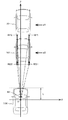
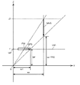
図8は、衝突予測時間の算出手順を説明するための図である。図8における点RP1は、図3において矢印a1に示される位置にある車両101を構成する後部バンパーの右側端部を示す点である。そして、図8における点RQ1は、図3において矢印a2に示される位置にある車両101を構成する後部バンパーの右側端部を示す点である。この点RP1は、特徴点P1に対応し、点RQ1は、特徴点Q1に対応している。以下、説明の便宜上、点RP1、点RQ1それぞれを、対応点RP1、対応点RQ1ともいう。また、車両101を構成する後部バンパーの右側端部を便宜上指標点ともいう。
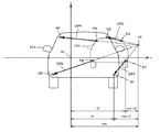
FIG. 8 is a diagram for explaining the procedure for calculating the predicted collision time. A point RP1 in FIG. 8 is a point indicating the right end portion of the rear bumper constituting the
図8におけるXYZ座標系は、車両100に搭載された撮影装置20の光学中心を原点Oとする直交座標系である。このXYZ座標系におけるZ軸は、撮影装置20の光軸と一致する。Y軸は、図8では不図示であるが、X軸及びZ軸と直交する。XYZ座標系におけるX座標及びY座標は、画像PH1,PH2に規定されたxy座標系におけるx座標及びy座標と一致する。図8における直線LN1は、撮影装置20の画像面IMを含む平面を示している。そして、直線LN2は、車両100の最も+Z側にある部分を含む衝突面を示している。
The XYZ coordinate system in FIG. 8 is an orthogonal coordinate system with the origin O as the optical center of the
本実施形態では、XYZ座標系の原点Oは、撮影装置20の光学中心と一致する。したがってXYZ座標系の原点Oから直線LN1までの距離は、撮影装置20の焦点距離fと等しい。また、原点Oと直線LN2との距離はLであるものとする。
In the present embodiment, the origin O of the XYZ coordinate system coincides with the optical center of the
画像PH1が撮影されたときに、図3における矢印a1に示される位置にある車両101は、画像PH2が撮影されたときには、図3における矢印a2に示される位置に移動している。この場合、図8を参照するとわかるように、特徴点P1を始点とし、特徴点Q1を終点とするオプティカルフローOP1に対応するXYZ座標系でのベクトルは、始点を対応点RP1とし、終点を対応点RQ1とするベクトルMV0となる。
When the image PH1 is photographed, the
オプティカルフローOP1は、撮影装置20の画像面IM内における特徴点の移動軌跡を示している。そして、ベクトルMV0は、XYZ座標系における対応点の移動軌跡を示している。車両101が、車両100に対してZ軸に平行に相対移動する場合には、ベクトルMV0はZ軸に平行となる。また、特徴点P1及び対応点RP1は、XYZ座標系において原点Oを通る直線LN3上に配置される。そして、特徴点Q1及び対応点RQ1は、XYZ座標系において原点Oを通る直線LN4上に配置される。
The optical flow OP <b> 1 indicates the movement trajectory of the feature point in the image plane IM of the
したがって、対応点RQ1と一致している車両101の指標点が、X座標をX1とするX軸上の点CP1に到達するまでの軌跡を示すベクトルMV2の大きさ|MV2|と、特徴点P1のX座標x2と、特徴点Q1のX座標x1と、ベクトルMV0の大きさ|MV0|との幾何学的な関係は、次式(5)で示される。
Accordingly, the magnitude | MV2 | of the vector MV2 indicating the trajectory until the index point of the
ここで、ベクトルMV0の大きさ|MV0|は、画像PH1が撮像された時刻から画像PH2が撮像された時刻までの時間Δtと、車両100に対する車両101の相対移動速度Vとの積(=V・Δt)である。また、ベクトルMV2の大きさ|MV2|は、指標点が対応点RQ1からX軸上の点CP1まで移動するのに要する時間TTCcと、相対移動速度Vとの積(=V・TTCc)である。
Here, the magnitude | MV0 | of the vector MV0 is the product of the time Δt from the time when the image PH1 is taken to the time when the image PH2 is taken and the relative movement speed V of the
そこで、上記式(5)の|MV2|に(V・TTCc)を代入し、|MV0|に(V・Δt)を代入して、両辺を相対移動速度Vで除することで、次式(6)が導かれる。 Therefore, by substituting (V · TTCc) for | MV2 | in the above equation (5), substituting (V · Δt) for | MV0 |, and dividing both sides by the relative movement speed V, the following equation ( 6) is derived.
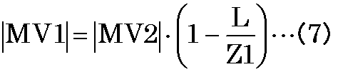
また、車両101の指標点が、対応点RQ1から直線LN2で示される衝突面上の点CP2に到達するまでの軌跡を示すベクトルMV1は、Z軸と平行である。そして、ベクトルMV1の大きさ|MV1|とベクトルMV2の大きさ|MV2|との関係は、X軸から対応点RQ1までの距離Z1と、X軸と点CP2までの距離Lを用いると次式(7)で示される。
Further, vector MV1 indicating the trajectory until the index point of
ここで、上述したように、ベクトルMV2の大きさ|MV2|は、指標点が対応点RQ1からX軸上の点CP1まで移動するのに要する時間TTCcと、相対移動速度Vとの積(=V・TTCc)である。また、ベクトルMV1の大きさ|MV1|は、指標点が対応点RQ1から直線LN2上の点CP2に到達するまでの衝突予測時間TTCと、相対移動速度Vとの積(=V・TTC)である。 Here, as described above, the magnitude | MV2 | of the vector MV2 is the product of the time TTCc required for the index point to move from the corresponding point RQ1 to the point CP1 on the X axis and the relative movement speed V (= V · TTCc). The magnitude | MV1 | of the vector MV1 is the product (= V · TTC) of the collision predicted time TTC until the index point reaches the point CP2 on the straight line LN2 from the corresponding point RQ1 and the relative movement speed V. is there.
相対移動速度Vは、オプティカルフローOP1〜OP4に関する情報を用いても求めることができない。そこで、上記式(7)の|MV2|に(V・TTCc)を代入し、|MV1|に(V・TTC)を代入して、両辺を相対移動速度Vで除することで、相対移動速度Vを含む項を含まない次式(8)を導く。 The relative movement speed V cannot be obtained using information on the optical flows OP1 to OP4. Therefore, by substituting (V · TTCc) for | MV2 | in the above formula (7) and substituting (V · TTC) for | MV1 | The following equation (8) not including a term including V is derived.
上記式(8)のLは、X軸と直線LN2で示される衝突面との距離であり、撮影装置20の取り付け位置と車両100の前端との距離にほぼ等しい既知の値である。このため、CPU31は、X軸と対応点RQ1との距離Z1の値がわかれば、上記式(8)を用いて、車両101が車両100に衝突するまでの衝突予測時間TTCを算出することが可能となる。
L in the above equation (8) is the distance between the X axis and the collision surface indicated by the straight line LN2, and is a known value that is substantially equal to the distance between the mounting position of the
そこで、CPU31は、次式(9)を用いて距離Z1を算出する。なお、fは撮影装置20の焦点距離である。また、δは、画像PH1,PH2を構成する画素のy軸方向の配列間隔である。また、hは、車両100が走行する路面と撮影装置20との距離である。また、ybは、図5に示されるように、画像PH2における、特徴点Q1と車両100が走行する路面との距離である。
Therefore, the
CPU31は、上記式(9)を用いて、距離Z1を算出すると、算出した距離Z1を上記式(8)に代入して、車両101が車両100に衝突するまでの衝突予測時間TTCを算出する。
When calculating the distance Z1 using the above equation (9), the
次に、障害物が車両100に対してZ軸と交差する方向へ相対移動するときに行われる衝突予測時間算出処理について説明する。
Next, a collision prediction time calculation process performed when the obstacle moves relative to the
例えば、車両100が+Z方向へ進行し、車両101がZ軸と交差する方向へ進行する場合を考える。この場合、撮影装置20の光学中心を原点OとするXYZ座標系では、車両101は、車両100の進行方向と車両101の進行方向とが合成された方向へ、相対的に移動することになる。
For example, consider a case where the
例えば、図9の矢印a1に示される位置にある車両101は、所定の時間が経過すると矢印a2に示される位置に相対的に移動する。この場合には、撮影装置20によって、まず矢印a1に示される位置にある車両101が撮影され、次に矢印a2に示される位置にある車両101が撮影される。
For example, the
図10には、CPU31によって規定されたオプティカルフローOP1〜OP4が示されている。車両101が、車両100に対してZ軸に交差する方向へ相対的に移動することにより車両100に接近する場合は、オプティカルフローOP1〜OP4の消失点VPは、xy座標系の原点Oと一致しない。
FIG. 10 shows optical flows OP1 to OP4 defined by the
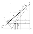
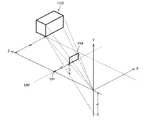
しかしながら、図11を参照するとわかるように、車両100の進行方向と車両101の進行方向が交差する場合にも、オプティカルフローOP1、ベクトルMV0、ベクトルMV2相互間の幾何学的関係は、車両100の進行方向と障害物の移動方向が等しいときのオプティカルフローOP1等との関係と等価である。このため、上記式(5)は成立する。したがって、図9における矢印a2に示される位置にある車両101が、車両100に衝突するまでの衝突予測時間TTCは、上記式(8)で表される。
However, as can be seen from FIG. 11, even when the traveling direction of the
図11に示されるように、直線LN5は、原点を通り、ベクトルMV0と直交する直線である。また、点CP3は、対応点RQ1と点CP1とを通る直線と、直線LN5との交点である。説明の便宜上、図11では、点CP3と点CP1とが、ある程度離間して記載されている。しかしながら、実際には、点CP3と点CP1との距離は、原点Oと直線LN2で示される衝突面との距離L等に比べて著しく小さい。このため、ベクトルMV2と平行で、対応点RQ1を始点とし、点CP3を終点とするベクトルMV3は、ベクトルMV2と大きさが等価であるものとして取り扱っても差し支えない。 As shown in FIG. 11, the straight line LN5 is a straight line that passes through the origin and is orthogonal to the vector MV0. Point CP3 is an intersection of a straight line passing through corresponding point RQ1 and point CP1 and straight line LN5. For the convenience of explanation, in FIG. 11, the point CP3 and the point CP1 are shown separated to some extent. However, in practice, the distance between the point CP3 and the point CP1 is significantly smaller than the distance L between the origin O and the collision surface indicated by the straight line LN2. Therefore, the vector MV3 that is parallel to the vector MV2 and that has the corresponding point RQ1 as the start point and the point CP3 as the end point may be handled as having the same size as the vector MV2.
そこで、CPU31は、車両101が直線LN5によって示される面に衝突するまでの時間TTCc0を、時間TTCcの近似値として、次式(10)に基づいて算出する。なお、xvpは消失点VPのX座標である。
Therefore, the
CPU31は、上記式(10)で算出した時間TTCc0を、時間TTCcとして、上記式(8)へ代入して、車両101が車両100に衝突するまでの衝突予測時間TTCを算出する。
The
図6に戻り、次のステップS105では、CPU31は、ステップS104で算出した衝突予測時間TTCが、予め設定された閾値THより大きいか否かを判定する。そして、衝突予測時間TTCが閾値THよりも大きいと判定した場合には(ステップS105:Yes)、ステップS102へ戻る。以降、CPU31は、ステップS105での判定が否定されるまで、ステップS102〜S105の処理を繰り返し実行する。一方、CPU31は、衝突予測時間TTCが閾値TH以下であると判定した場合には(ステップS105:No)、ステップS106へ移行する。
Returning to FIG. 6, in the next step S105, the
ステップS106では、CPU31は、画像PH2に写る障害物の検出を試みる。具体的には、CPU31は、画像PH2に、障害物の検出を行う領域を規定するフレームFMを設定する。このフレームFMは、図12に示されるように、グルーピングされた1群のオプティカルフローOP1〜OP4を含み、フレームFMによって囲まれる領域が最も小さくなるように設定される。本実施形態では、フレームFMが障害物が位置する領域を示す指標となる。
In step S106, the
図12に示される例では、グルーピングされたオプティカルフローOP1〜OP4のうちの3つのオプティカルフローOP1,OP2,OP4の終点によって、フレームFMが規定されている。 In the example shown in FIG. 12, the frame FM is defined by the end points of three optical flows OP1, OP2, and OP4 among the grouped optical flows OP1 to OP4.
CPU31は、フレームFMを設定すると、フレームFMに囲まれる画像に対して、テンプレートのマッチングを行う。マッチングに用いるテンプレートとしては、例えば車両の後部の画像、ガードレールの画像などが考えられる。CPU31は、種々のテンプレートをフレームFMに囲まれる画像に対してマッチングさせて、各テンプレートについての相関値をそれぞれ算出する。
When the
次のステップS107では、CPU31は、ステップS106で算出された相関値から、自車前方に位置する障害物が、ガードレールや標識に代表される静止物であるかいなかを判定する。例えば、自車前方にガードレールが位置していた場合には、ステップS106で算出される相関値は、ガードレールの画像をマッチングさせたときに最も大きくなる。そこで、CPU31は、ガードレールの画像の相関値が、ステップS106で求めた相関値のうちで最も大きく、かつ所定の閾値を上回る場合に、フレームFMに囲まれる画像が、ガードレールなどの静止物の画像であると判定する(ステップS107:Yes)。そして、ステップS108へ移行する。
In the next step S107, the
ステップS108では、CPU31は、距離算出処理1を実行する。この距離算出処理1は、車両100に対する障害物の移動方向に直交する方向における、当該車両100と障害物との距離wxを算出するための処理である。障害物が静止物である場合や、車両100に対する障害物の移動方向が、XYZ座標系におけるZ軸に平行な方向である場合には、距離wxは、車両100と障害物とのX軸方向の距離を表す。
In step S108, the
例えば、ガードレールGRのような静止物は、車両100の進行方向に平行な直線に沿って相対移動しながら、車両100に接近する。このため、ガードレールGRが車両100に接近する場合には、図13に示されるように、例えばオプティカルフローOP5〜OP8が規定される。この場合には、フレームFM、オプティカルフローOP5、及びガードレールの移動軌跡を示すベクトルMV5のXYZ座標系における位置関係は、図14に示されるようになる。なお、図14中の、w1は、画像PH2における消失点VPからフレームFMの端までの距離であり、wxは、車両100と障害物との距離である。また、vzは、車両100の速度であり、Sfは、撮影装置20のスケールファクタである。
For example, a stationary object such as the guard rail GR approaches the
そこで、CPU31は、次式(11)を用いて、車両100の進行方向に直交する方向(XYZ座標系におけるX軸方向)に関する車両100と障害物との距離wxを算出する。
Therefore, the
ステップS107の処理において、ガードレールなどの静止物の画像をマッチングさせたときの相関値が所定の閾値以下となった場合には、CPU31は、フレームFMに囲まれる画像が静止物の画像ではないと判定し(ステップS107:No)、ステップS109へ移行する。
In the process of step S107, if the correlation value when matching an image of a stationary object such as a guardrail is equal to or less than a predetermined threshold, the
ステップS109では、CPU31は、フレームFMに囲まれる領域に写る障害物と路面との境界の検出を試みる。例えば障害物が、車両100の前方を走行する車両101であって、当該車両101の後方へ直射日光があたっているときには、画像PH2に対して画像処理を実行することにより、当該車両101のタイヤと路面との境界を検出することができる。一方、当該車両101の前方へ直射日光があたると、当該車両101の後方に影ができるため、画像PH2に対して画像処理を実行したとしても、当該車両101のタイヤと路面との境界を検出するのが困難になる。
In step S109, the
CPU31は、画像PH2に対する画像処理によって、フレームFMに囲まれる領域に写る障害物と路面との境界が検出できたときには(ステップS109:Yes)、ステップS110へ移行する。
When the
ステップS110では、CPU31は、距離算出処理2を実行する。この距離算出処理2では、ステップS108で実行される距離算出処理1と比較して、演算に用いられる数式が異なる。
In step S110, the
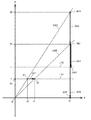
例えば図5に示されるように、車両101と路面との路面境界BLが検出された場合は、画像PH2における消失点VPから路面境界までの距離v1と、路面に対する撮影装置20の高さHと、画像PH2における消失点VPからフレームFMまでの距離w1と、車両100と障害物102までの距離wxとの関係は、図15に示されるようになる。そこで、CPU31は、次式(12)を用いて、距離wxを算出する。
For example, as shown in FIG. 5, when the road surface boundary BL between the
ステップS109の処理において、画像PH2に対する画像処理によって、フレームFMに囲まれる領域に写る障害物と路面との境界が検出できなかったときには(ステップS109:No)、CPU31は、ステップS111へ移行する。
In the process of step S109, when the boundary between the obstacle and the road surface reflected in the area surrounded by the frame FM cannot be detected by the image process on the image PH2, the
ステップS111では、CPU31は、ステップS106で算出された相関値から、車両100の前方に位置する障害物が、車両であるか否かを判定する。例えば、車両100の前方に車両が位置していた場合には、ステップS106で算出される相関値は、車両の画像をマッチングさせたときに最も大きくなる。そこで、CPU31は、車両の画像をマッチングさせたときの相関値が、ステップS106で求めた相関値のうちで最も大きく、かつ所定の閾値を上回る場合に、フレームFMに囲まれる画像が、車両の画像であると判定する(ステップS111:Yes)。そして、ステップS112へ移行する。
In step S111, the
ステップS112では、CPU31は、距離算出処理3を実行する。この距離算出処理3では、ステップS108,S110で実行される距離算出処理1,2と比較して、演算に用いられる数式が異なる。
In step S112, the
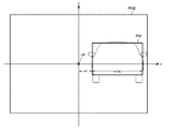
フレームFMに囲まれる画像が車両の画像である場合には、フレームFMの幅は、概ね車両100の前方を走行する前方車両の幅に対応した大きさになる。例えば、図16に示されるように、画像PH2におけるフレームFMの幅をwobjとし、消失点VPからフレームFMまでの距離をw1とする。また、前方車両の幅をWcとすると、車両101までの距離wxは、次式(13)で示される。そこで、CPU31は、次式(13)を用いて、距離wxを算出する。なお、前方車両の幅Wcは、一般的な車両の幅を想定したものであり、例えばその値を1.7mとすることが考えられる。幅Wcの値は、予め設定され、判定装置30に記憶されている。
When the image surrounded by the frame FM is an image of the vehicle, the width of the frame FM is approximately the size corresponding to the width of the front vehicle traveling in front of the
また、ステップS111の処理において、車両の画像をマッチングさせたときの相関値が所定の閾値以下となった場合には、CPU31は、フレームFMに囲まれる画像が車両の画像ではないと判定し(ステップS111:No)、ステップS113へ移行する。
In the process of step S111, if the correlation value when matching the vehicle image is equal to or less than a predetermined threshold, the
ステップS113では、CPU31は、距離算出処理4を実行する。この距離算出処理4では、ステップS112で実行される距離算出処理3と比較して、演算に用いられるパラメータが異なる。一般に、走行する車両100の前方に障害物が存在する場合は、この障害物は車両である蓋然性が極めて高い。そこで、CPU31は、上記式(13)のパラメータWcを、当該パラメータWcよりも値が小さいパラメータWukに代えることにより得られる次式(14)を用いて、距離wxを算出する。パラメータWukの値は、前方車両の幅Wcに所定の係数を乗じることにより決定され、例えば所定の係数は1前後とすることが考えられる。パラメータWukの値は、予め設定され、判定装置30に記憶されている。
In step S113, the
ステップS113で算出される距離wxは、車両100と障害物との実際の距離よりも小さくなる。このため、衝突が生じる前に余裕をもって、ドライバへ警報等を発令することが可能となる。
The distance wx calculated in step S113 is smaller than the actual distance between the
次のステップS114では、CPU31は、ステップS108,S110,S112,S113で算出した距離wxに用いて、障害物が車両100に衝突するか否かを判定する。この判定の際には、障害物が車両100の進行方向と平行な方向へ相対移動するときと、障害物が車両の進行方向と交差する方向へ相対移動するときとで、異なる処理が行われる。そこで、まず障害物が車両の進行方向と平行な方向へ相対移動するときに行われる判定処理について説明する。
In the next step S114, the
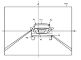
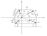
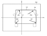
図17は、XYZ座標系における車両100,101、及びフレームFMとの位置関係を示す図である。図17を参照するとわかるように、車両101が矢印A1に示されるようにZ軸に平行に移動する場合、すなわち、車両100の進行方向と、車両100に接近する障害物の相対的な移動方向が平行な場合には、消失点VPは、XYZ座標系におけるZ軸上に規定される。
FIG. 17 is a diagram illustrating a positional relationship between the
この場合CPU31は、撮影装置20から車両100の右側面までの距離Wcr、或いは撮影装置20から車両100の左側面までの距離Wclと、距離wxとを比較する。そして、距離Wcr、或いは距離Wclの値が、距離wxの値より小さい場合には、車両101などの障害物と車両100が衝突する可能性がないと判定する(ステップS114:No)。また、距離Wcr、或いは距離Wclの値が、距離wxの値以上の場合には、車両101などの障害物と車両100が衝突する可能性があると判定する(ステップS114:Yes)。
In this case, the
次に、障害物が車両の進行方向と交差する方向へ相対移動するときに行われる判定処理について説明する。 Next, a determination process performed when the obstacle moves relative to the direction intersecting the traveling direction of the vehicle will be described.
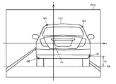
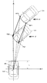
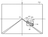
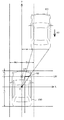
図18は、XYZ座標系における車両100,101、及びフレームFMとの位置関係を示す図である。ベクトルA2に示されるように、車両101が、車両100の進行方向と交差する方向に相対移動しながら、車両100に接近するときは、CPU31は、衝突予測時間TTCが経過したときに車両100に接し、ベクトルA2と平行な2本の直線Lr,Llと、消失点VPを通りベクトルA2に平行な直線Lcとの距離dr,dlを、次式(15)及び(16)を用いてそれぞれ算出する。なお、xvpは、消失点VPのX座標である。また、距離Lcfは、撮影装置20から車両100の前端までの距離であり、距離Lcrは、撮影装置20から車両100の後端までの距離である。
FIG. 18 is a diagram illustrating a positional relationship between the
CPU31は、距離dr,dlを算出すると、これらの距離dr,或いは距離dlと、距離wxを比較する。そして、距離dr、或いは距離dlの値が、距離wxの値より小さい場合には、車両101などの障害物と車両100が衝突する可能性がないと判定する(ステップS114:No)。また、距離dr、或いは距離dlの値が、距離w1の値以上の場合には、車両101などの障害物と車両100が衝突する可能性があると判定する(ステップS114:Yes)。
When calculating the distances dr and dl, the
CPU31は、ステップS114で、障害物と車両100が衝突する可能性がないと判定した場合には(ステップS114:No)、ステップS102に戻り、以降ステップS102〜S114の処理を繰り返す。一方、CPU31は、ステップS114で、障害物と車両100が衝突する可能性があると判定した場合には(ステップS114:Yes)、ステップS115へ移行する。
If the
ステップS115では、CPU31は、警報装置40へ警報の発令を指示する。これにより、車両100のドライバに対して、障害物が車両100に衝突する可能性があることが報知される。ステップS115の処理が終了すると、CPU31は、ステップS102へ戻る。そして、ステップS102以降の処理を繰り返し実行する。
In step S115, the
以上説明したように、本実施形態では、画像に写る障害物の位置を示すフレームFMと、当該障害物についてのオプティカルフローの消失点VPとの距離w1が求められる。そして、距離w1を用いて、車両100に対する障害物の相対移動方向に直交する方向についての、車両100と障害物との距離wxが算出される(ステップS108,S110,S112,S113)。これにより、距離wxと、車両100に搭載された撮影装置20と車両100の側面までの距離とを比較することにより、車両100と障害物とが衝突するか否かを精度よく判定することができる(ステップS114)。
As described above, in this embodiment, the distance w1 between the frame FM indicating the position of the obstacle in the image and the vanishing point VP of the optical flow for the obstacle is obtained. Then, using the distance w1, the distance wx between the
そして、判定結果に基づいて、障害物と車両100とが衝突する可能性がある場合に限り、車両100のドライバに警報を発令することが可能となる(ステップS115)。したがって、ドライバの運転を、適切に支援することが可能となる。
Based on the determination result, an alarm can be issued to the driver of the
本実施形態では、画像に写る障害物が静止物か、或いは車両であるか否かが判断される(ステップS107,S109,S111)。そして、判断結果に応じた手順で、消失点VPからフレームFMまでの距離w1が算出される。このため、障害物の種類に応じて、衝突可能性の正確な判定が可能となる。したがって、ドライバの運転を、適切に支援することができる。 In the present embodiment, it is determined whether the obstacle reflected in the image is a stationary object or a vehicle (steps S107, S109, S111). Then, the distance w1 from the vanishing point VP to the frame FM is calculated by a procedure according to the determination result. For this reason, it is possible to accurately determine the possibility of collision according to the type of obstacle. Therefore, it is possible to appropriately support the driving of the driver.
以上、本発明の実施形態について説明したが、本発明は上記実施形態によって限定されるものではない。例えば、上記実施形態に係る判定装置30の機能は、ハードウェアによっても実現することができる。
As mentioned above, although embodiment of this invention was described, this invention is not limited by the said embodiment. For example, the function of the
一例として、図19には変形例に係る判定装置30のブロック図が示されている。図19に示されるように、この判定装置30は、記憶部30a,オプティカルフロー算出部30b、予測時間算出部30c、属性判別部30d、距離算出部30e、及び判定部30fを有している。
As an example, FIG. 19 shows a block diagram of a
例えば、オプティカルフロー算出部30bは、図6に示されるステップS102,S103に係る処理を実行する。予測時間算出部30cは、ステップS104,S105に係る処理を実行する。属性判別部30dは、ステップS106,S107,S109,S111に係る処理を実行する。距離算出部30eは、ステップS108,S110,S112,S113に係る処理を実行する。判定部30fは、ステップS114,S115に係る処理を実行する。記憶部30aは、上記各部30b〜30fの処理結果や、撮影装置20から出力される画像情報を記憶する。
For example, the optical flow calculation unit 30b executes the processes related to steps S102 and S103 shown in FIG. The predicted time calculation unit 30c executes processing related to steps S104 and S105. The
第1の実施形態において判定装置30の補助記憶部33に記憶されているプログラムは、フレキシブルディスク、CD−ROM(Compact Disk Read-Only Memory)、DVD(Digital Versatile Disk)、MO(Magneto-Optical disk)等のコンピュータで読み取り可能な記録媒体に格納して配布し、そのプログラムをコンピュータにインストールすることにより、上述の処理を実行する装置を構成することとしてもよい。
In the first embodiment, the programs stored in the
また、プログラムをインターネット等の通信ネットワーク上の所定のサーバ装置が有するディスク装置等に格納しておき、例えば、搬送波に重畳させて、コンピュータにダウンロード等するようにしても良い。 Further, the program may be stored in a disk device or the like included in a predetermined server device on a communication network such as the Internet, and may be downloaded onto a computer by being superimposed on a carrier wave, for example.
なお、本発明は、本発明の広義の精神と範囲を逸脱することなく、様々な実施形態及び変形が可能とされるものである。また、上述した実施形態は、本発明を説明するためのものであり、本発明の範囲を限定するものではない。 It should be noted that the present invention can be variously modified and modified without departing from the broad spirit and scope of the present invention. Further, the above-described embodiment is for explaining the present invention, and does not limit the scope of the present invention.
本発明の距離算出装置、距離算出方法、及びプログラムは、車両と障害物との距離を算出するのに適している。また、本発明の衝突検出システム、衝突検出方法、及びプログラムは、車両と障害物との衝突の検出に適している。 The distance calculation device, the distance calculation method, and the program of the present invention are suitable for calculating the distance between the vehicle and the obstacle. The collision detection system, collision detection method, and program of the present invention are suitable for detecting a collision between a vehicle and an obstacle.
10 衝突判定システム
20 撮影装置
30 判定装置
30a 記憶部
30b オプティカルフロー算出部
30c 予測時間算出部
30d 属性判別部
30e 距離算出部
30f 判定部
31 CPU
32 主記憶部
33 補助記憶部
34 表示部
35 インタフェース部
40 警報装置
100,101 車両
102 障害物
BL 路面境界
CP1〜CP3 点
FM フレーム
GR ガードレール
IM 画像面
M 画素
MV0〜MV5 ベクトル
OP1〜OP8 オプティカルフロー
PH,PH1,PH2 画像
P1〜P4 特徴点
Q1〜Q4 特徴点
VP 消失点
DESCRIPTION OF
32
Claims (14)
前記撮影手段によって撮影された第1画像に写る障害物の特徴点を始点とし、前記第1画像が撮影された後に撮影された第2画像に写る障害物の特徴点を終点とする複数のオプティカルフローを算出するオプティカルフロー算出手段と、
前記車両に対して前記障害物が移動する第1方向に直交する第2方向についての、前記オプティカルフローの消失点と前記画像に写る障害物との第1距離に基づいて、前記車両と前記障害物との前記第2方向についての第2距離を算出する距離算出手段と、
を備える距離算出装置。 Photographing means for sequentially photographing the traveling direction of the vehicle;
A plurality of optical elements starting from a feature point of an obstacle appearing in the first image taken by the photographing means and ending at a feature point of the obstacle appearing in a second image taken after the first image is taken An optical flow calculating means for calculating the flow;
Based on the first distance between the vanishing point of the optical flow and the obstacle appearing in the image in a second direction orthogonal to the first direction in which the obstacle moves relative to the vehicle, the vehicle and the obstacle Distance calculating means for calculating a second distance with respect to the object in the second direction;
A distance calculation device comprising:
前記障害物の前記オプティカルフローによって規定されるフレームと、前記消失点の距離を前記第1距離として、前記第2距離を算出する請求項1に記載の距離算出装置。 The distance calculating means includes
The distance calculation apparatus according to claim 1, wherein the second distance is calculated by setting a distance between the frame defined by the optical flow of the obstacle and the vanishing point as the first distance.
前記第1方向が、前記車両の進行方向に交差する場合には、前記オプティカルフローの消失点を通り前記第1方向に平行な第1直線と前記障害物との距離を、前記第2距離として算出する請求項1又は2に記載の距離算出装置。 The distance calculating means includes
When the first direction intersects the traveling direction of the vehicle, the distance between the first straight line passing through the vanishing point of the optical flow and parallel to the first direction is the second distance. The distance calculation apparatus according to claim 1 or 2, wherein the distance calculation device calculates the distance.
前記距離算出手段は、
前記判別手段の判別結果に応じた距離算出手順で、前記第2距離を算出する請求項1乃至3のいずれか一項に記載の距離算出装置。 A discriminating means for discriminating an attribute of an obstacle reflected in the second image;
The distance calculating means includes
The distance calculation apparatus according to claim 1, wherein the second distance is calculated by a distance calculation procedure according to a determination result of the determination unit.
前記判別手段によって前記障害物が静止物と判断された場合に、
前記第2画像における前記消失点から前記障害物までの前記第1距離に基づいて、
前記車両と前記障害物が衝突するまでの衝突予測時間と、
前記車両の速度と、
前記撮影手段のスケールファクタと、
を用いて前記第2距離を算出する請求項4に記載の距離算出装置。 The distance calculating means includes
When the obstacle is determined as a stationary object by the determining means,
Based on the first distance from the vanishing point to the obstacle in the second image,
Collision prediction time until the vehicle and the obstacle collide,
The speed of the vehicle;
A scale factor of the imaging means;
The distance calculation apparatus according to claim 4, wherein the second distance is calculated by using a computer.
前記判別手段によって前記障害物と前記車両が走行する路面の境界が検出された場合に、
前記第2画像における前記消失点から前記障害物までの前記第1距離に基づいて、
前記第2画像における前記消失点から前記路面までの距離と、
前記路面に対する前記撮影手段の高さと、
を用いて前記第2距離を算出する請求項4又は5に記載の距離算出装置。 The distance calculating means includes
When a boundary between the obstacle and the road surface on which the vehicle travels is detected by the determination means,
Based on the first distance from the vanishing point to the obstacle in the second image,
A distance from the vanishing point to the road surface in the second image;
The height of the photographing means relative to the road surface;
The distance calculation apparatus according to claim 4, wherein the second distance is calculated using a computer.
前記判別手段によって前記障害物が前記車両の前方を走行する前方車両と判断された場合に、
前記第2画像における前記消失点から前記障害物までの前記第1距離に基づいて、
前記第2画像における前記前方車両の幅と、
予め想定され設定された車両の幅と、
を用いて前記第2距離を算出する請求項4乃至6のいずれか一項に記載の距離算出装置。 The distance calculating means includes
When it is determined by the determining means that the obstacle is a forward vehicle traveling in front of the vehicle,
Based on the first distance from the vanishing point to the obstacle in the second image,
The width of the preceding vehicle in the second image;
Vehicle width assumed and set in advance,
The distance calculation device according to any one of claims 4 to 6, wherein the second distance is calculated by using a computer.
前記判別手段によって前記障害物の属性が判別できなかった場合に、
前記第2画像における前記消失点から前記障害物までの前記第1距離に基づいて、
前記第2画像における前記障害物の幅と、
予め想定された車両の幅に所定の係数を乗じて得られるパラメータと、
を用いて前記第2距離を算出する請求項4乃至7のいずれか一項に記載の距離算出装置。 The distance calculating means includes
When the attribute of the obstacle cannot be determined by the determining means,
Based on the first distance from the vanishing point to the obstacle in the second image,
The width of the obstacle in the second image;
A parameter obtained by multiplying a predetermined vehicle width by a predetermined coefficient;
The distance calculation apparatus according to any one of claims 4 to 7, wherein the second distance is calculated by using a computer.
前記距離算出装置によって算出された第2距離に基づいて、前記車両と前記障害物とが衝突するか否かを判定する判定手段と、
を備える衝突検出システム。 The distance calculation device according to any one of claims 1 to 8,
Determining means for determining whether or not the vehicle and the obstacle collide based on the second distance calculated by the distance calculating device;
A collision detection system comprising:
前記判定手段は、
前記予測時間が経過したときに前記車両が位置するところを予測し、前記車両に接し前記第1直線と平行な第2直線と前記第1直線との第3距離と、前記第2距離との比較結果に基づいて、前記車両と前記障害物とが衝突するか否かを判定する請求項9に記載の衝突検出システム。 Based on the size of the optical flow of the obstacle and the time from the time when the first image was taken to the time when the second image was taken, an object in the field of view of the photographing means is the vehicle. Provided with a predicted time calculation means for calculating a predicted time until a collision with
The determination means includes
When the predicted time elapses, the vehicle is predicted to be located, a third distance between the second straight line that is in contact with the vehicle and parallel to the first straight line, and the second straight line, and the second distance The collision detection system according to claim 9, wherein it is determined whether or not the vehicle and the obstacle collide based on a comparison result.
撮影された第1画像に写る障害物の特徴点を始点とし、前記第1画像が撮影された後に撮影された第2画像に写る障害物の特徴点を終点とする複数のオプティカルフローを算出する工程と、
前記車両に対して前記障害物が移動する第1方向に直交する第2方向についての、前記オプティカルフローの消失点と前記画像に写る障害物との第1距離を求める工程と、
前記車両と前記障害物との前記第2方向についての第2距離を算出する工程と、
を含む距離算出方法。 A step of sequentially photographing the traveling direction of the vehicle;
A plurality of optical flows starting from the feature points of the obstacle appearing in the first image taken and starting from the feature points of the obstacle appearing in the second image taken after the first image is taken are calculated. Process,
Obtaining a first distance between the vanishing point of the optical flow and the obstacle reflected in the image in a second direction orthogonal to the first direction in which the obstacle moves relative to the vehicle;
Calculating a second distance between the vehicle and the obstacle in the second direction;
Distance calculation method including
車両の前方を撮影することにより得られた第1画像に写る障害物の特徴点を始点とし、前記第1画像が撮影された後に、前記車両の前方を撮影することにより得られた第2画像に写る障害物の特徴点を終点とする複数のオプティカルフローを算出する手順と、
前記車両に対して前記障害物が移動する第1方向に直交する第2方向についての、前記オプティカルフローの消失点と前記画像に写る障害物との第1距離を求める手順と、
前記車両と前記障害物との前記第2方向についての第2距離を算出する手順と、
を実行させるためのプログラム。 On the computer,
A second image obtained by photographing the front of the vehicle after the first image is photographed, starting from the feature point of the obstacle in the first image obtained by photographing the front of the vehicle. A procedure for calculating a plurality of optical flows whose end points are feature points of obstacles appearing in
A procedure for obtaining a first distance between a vanishing point of the optical flow and an obstacle reflected in the image in a second direction orthogonal to a first direction in which the obstacle moves with respect to the vehicle;
Calculating a second distance between the vehicle and the obstacle in the second direction;
A program for running
前記第2距離に基づいて、前記車両と前記障害物とが衝突するか否かを判定する手順を実行させるための請求項13に記載のプログラム。 On the computer,
The program according to claim 13 for executing a procedure of determining whether or not the vehicle and the obstacle collide based on the second distance.
Priority Applications (1)
| Application Number | Priority Date | Filing Date | Title |
|---|---|---|---|
| JP2012261529A JP2014106901A (en) | 2012-11-29 | 2012-11-29 | Distance calculation device, collision detection system, distance calculation method, collision detection method, and program |
Applications Claiming Priority (1)
| Application Number | Priority Date | Filing Date | Title |
|---|---|---|---|
| JP2012261529A JP2014106901A (en) | 2012-11-29 | 2012-11-29 | Distance calculation device, collision detection system, distance calculation method, collision detection method, and program |
Publications (1)
| Publication Number | Publication Date |
|---|---|
| JP2014106901A true JP2014106901A (en) | 2014-06-09 |
Family
ID=51028289
Family Applications (1)
| Application Number | Title | Priority Date | Filing Date |
|---|---|---|---|
| JP2012261529A Pending JP2014106901A (en) | 2012-11-29 | 2012-11-29 | Distance calculation device, collision detection system, distance calculation method, collision detection method, and program |
Country Status (1)
| Country | Link |
|---|---|
| JP (1) | JP2014106901A (en) |
Cited By (12)
| Publication number | Priority date | Publication date | Assignee | Title |
|---|---|---|---|---|
| JP2017027592A (en) * | 2015-07-23 | 2017-02-02 | 三菱電機株式会社 | Method and system for segmenting images |
| CN106846908A (en) * | 2016-12-27 | 2017-06-13 | 东软集团股份有限公司 | The danger judgement method and apparatus of road |
| JP2017528772A (en) * | 2014-06-13 | 2017-09-28 | トムトム インターナショナル ベスローテン フエンノートシャップ | Method and system for generating route data |
| JP2017194926A (en) * | 2016-04-22 | 2017-10-26 | 株式会社デンソー | Vehicle control apparatus and vehicle control method |
| CN110194152A (en) * | 2018-02-27 | 2019-09-03 | 株式会社万都 | The autonomous emergency braking system and method located at the parting of the ways for vehicle |
| JP2019175439A (en) * | 2018-02-21 | 2019-10-10 | ホンダ リサーチ インスティテュート ヨーロッパ ゲーエムベーハーHonda Research Institute Europe GmbH | Optical flow based assistance for operation and coordination in dynamic environment |
| JP2020140457A (en) * | 2019-02-28 | 2020-09-03 | トヨタ自動車株式会社 | Collision detection server, program and recording medium |
| US10861325B2 (en) | 2014-09-07 | 2020-12-08 | Tomtom Traffic B.V. | Methods and systems for identifying navigable elements affected by weather conditions |
| CN113486836A (en) * | 2021-07-19 | 2021-10-08 | 安徽江淮汽车集团股份有限公司 | Automatic driving control method for low-pass obstacle |
| GB2598082A (en) * | 2020-07-08 | 2022-02-23 | Continental Automotive Gmbh | Road mirror detection system and method |
| US20220080974A1 (en) * | 2020-09-17 | 2022-03-17 | Hyundai Motor Company | Vehicle and method of controlling the same |
| US12307783B2 (en) | 2021-05-24 | 2025-05-20 | Toyota Jidosha Kabushiki Kaisha | Apparatus and method for estimating distance and non-transitory computer-readable medium containing computer program for estimating distance |
-
2012
- 2012-11-29 JP JP2012261529A patent/JP2014106901A/en active Pending
Cited By (19)
| Publication number | Priority date | Publication date | Assignee | Title |
|---|---|---|---|---|
| US10768006B2 (en) | 2014-06-13 | 2020-09-08 | Tomtom Global Content B.V. | Methods and systems for generating route data |
| US12292298B2 (en) | 2014-06-13 | 2025-05-06 | Tom Tom Global Content B.V. | Methods and systems for generating route data |
| JP2017528772A (en) * | 2014-06-13 | 2017-09-28 | トムトム インターナショナル ベスローテン フエンノートシャップ | Method and system for generating route data |
| US11740099B2 (en) | 2014-06-13 | 2023-08-29 | Tomtom Global Content B.V. | Methods and systems for generating route data |
| US10861325B2 (en) | 2014-09-07 | 2020-12-08 | Tomtom Traffic B.V. | Methods and systems for identifying navigable elements affected by weather conditions |
| JP2017027592A (en) * | 2015-07-23 | 2017-02-02 | 三菱電機株式会社 | Method and system for segmenting images |
| WO2017183668A1 (en) * | 2016-04-22 | 2017-10-26 | 株式会社デンソー | Vehicle control device and vehicle control method |
| US11288961B2 (en) | 2016-04-22 | 2022-03-29 | Denso Corporation | Vehicle control apparatus and vehicle control method |
| JP2017194926A (en) * | 2016-04-22 | 2017-10-26 | 株式会社デンソー | Vehicle control apparatus and vehicle control method |
| CN106846908A (en) * | 2016-12-27 | 2017-06-13 | 东软集团股份有限公司 | The danger judgement method and apparatus of road |
| JP2019175439A (en) * | 2018-02-21 | 2019-10-10 | ホンダ リサーチ インスティテュート ヨーロッパ ゲーエムベーハーHonda Research Institute Europe GmbH | Optical flow based assistance for operation and coordination in dynamic environment |
| CN110194152A (en) * | 2018-02-27 | 2019-09-03 | 株式会社万都 | The autonomous emergency braking system and method located at the parting of the ways for vehicle |
| JP2020140457A (en) * | 2019-02-28 | 2020-09-03 | トヨタ自動車株式会社 | Collision detection server, program and recording medium |
| GB2598082A (en) * | 2020-07-08 | 2022-02-23 | Continental Automotive Gmbh | Road mirror detection system and method |
| US20220080974A1 (en) * | 2020-09-17 | 2022-03-17 | Hyundai Motor Company | Vehicle and method of controlling the same |
| US11713044B2 (en) * | 2020-09-17 | 2023-08-01 | Hyundai Motor Company | Vehicle for estimation a state of the other vehicle using reference point of the other vehicle, and method of controlling the vehicle |
| US12307783B2 (en) | 2021-05-24 | 2025-05-20 | Toyota Jidosha Kabushiki Kaisha | Apparatus and method for estimating distance and non-transitory computer-readable medium containing computer program for estimating distance |
| CN113486836A (en) * | 2021-07-19 | 2021-10-08 | 安徽江淮汽车集团股份有限公司 | Automatic driving control method for low-pass obstacle |
| CN113486836B (en) * | 2021-07-19 | 2023-06-06 | 安徽江淮汽车集团股份有限公司 | Automatic driving control method for low-pass obstacle |
Similar Documents
| Publication | Publication Date | Title |
|---|---|---|
| JP2014106901A (en) | Distance calculation device, collision detection system, distance calculation method, collision detection method, and program | |
| JP5944781B2 (en) | Mobile object recognition system, mobile object recognition program, and mobile object recognition method | |
| JP6473571B2 (en) | TTC measuring device and TTC measuring program | |
| CN102194239B (en) | For the treatment of the method and system of view data | |
| JP6328327B2 (en) | Image processing apparatus and image processing method | |
| JP2018060326A (en) | Tracking device and program thereof | |
| JP6139465B2 (en) | Object detection device, driving support device, object detection method, and object detection program | |
| JP6816401B2 (en) | Image processing device, imaging device, mobile device control system, image processing method, and program | |
| EP3193229B1 (en) | Mobile body control device and mobile body | |
| JP2010256995A (en) | Object recognition apparatus | |
| Kim et al. | Vehicle path prediction based on radar and vision sensor fusion for safe lane changing | |
| JP5418427B2 (en) | Collision time calculation device, collision time calculation method and program | |
| JP2020118575A (en) | Inter-vehicle distance measurement device, error model generation device, learning model generation device, and method and program thereof | |
| JP5832850B2 (en) | Lane monitoring system and lane monitoring method | |
| JP5717416B2 (en) | Driving support control device | |
| JP2006027481A (en) | Object warning device and object warning method | |
| JP3319383B2 (en) | Roadway recognition device | |
| JP4106163B2 (en) | Obstacle detection apparatus and method | |
| JP6057660B2 (en) | Lane monitoring system and lane monitoring method | |
| JP2021148730A (en) | Position estimation method, position estimation device, and program | |
| JP7309630B2 (en) | Image processing device | |
| JP6295868B2 (en) | Vehicle display device | |
| CN112513573B (en) | Stereo camera device | |
| JP2004038760A (en) | Roadway recognition device for vehicles | |
| JP6361347B2 (en) | Vehicle display device |