WO2022130571A1 - 電動機駆動装置、冷凍サイクル装置、及び空気調和機 - Google Patents
電動機駆動装置、冷凍サイクル装置、及び空気調和機 Download PDFInfo
- Publication number
- WO2022130571A1 WO2022130571A1 PCT/JP2020/047186 JP2020047186W WO2022130571A1 WO 2022130571 A1 WO2022130571 A1 WO 2022130571A1 JP 2020047186 W JP2020047186 W JP 2020047186W WO 2022130571 A1 WO2022130571 A1 WO 2022130571A1
- Authority
- WO
- WIPO (PCT)
- Prior art keywords
- value
- axis
- mode
- voltage
- axis voltage
- Prior art date
- Legal status (The legal status is an assumption and is not a legal conclusion. Google has not performed a legal analysis and makes no representation as to the accuracy of the status listed.)
- Ceased
Links
Images





Classifications
-
- F—MECHANICAL ENGINEERING; LIGHTING; HEATING; WEAPONS; BLASTING
- F24—HEATING; RANGES; VENTILATING
- F24F—AIR-CONDITIONING; AIR-HUMIDIFICATION; VENTILATION; USE OF AIR CURRENTS FOR SCREENING
- F24F11/00—Control or safety arrangements
- F24F11/30—Control or safety arrangements for purposes related to the operation of the system, e.g. for safety or monitoring
- F24F11/46—Improving electric energy efficiency or saving
-
- H—ELECTRICITY
- H02—GENERATION; CONVERSION OR DISTRIBUTION OF ELECTRIC POWER
- H02P—CONTROL OR REGULATION OF ELECTRIC MOTORS, ELECTRIC GENERATORS OR DYNAMO-ELECTRIC CONVERTERS; CONTROLLING TRANSFORMERS, REACTORS OR CHOKE COILS
- H02P21/00—Arrangements or methods for the control of electric machines by vector control, e.g. by control of field orientation
- H02P21/22—Current control, e.g. using a current control loop
-
- F—MECHANICAL ENGINEERING; LIGHTING; HEATING; WEAPONS; BLASTING
- F24—HEATING; RANGES; VENTILATING
- F24F—AIR-CONDITIONING; AIR-HUMIDIFICATION; VENTILATION; USE OF AIR CURRENTS FOR SCREENING
- F24F11/00—Control or safety arrangements
- F24F11/70—Control systems characterised by their outputs; Constructional details thereof
- F24F11/80—Control systems characterised by their outputs; Constructional details thereof for controlling the temperature of the supplied air
- F24F11/86—Control systems characterised by their outputs; Constructional details thereof for controlling the temperature of the supplied air by controlling compressors within refrigeration or heat pump circuits
-
- F—MECHANICAL ENGINEERING; LIGHTING; HEATING; WEAPONS; BLASTING
- F25—REFRIGERATION OR COOLING; COMBINED HEATING AND REFRIGERATION SYSTEMS; HEAT PUMP SYSTEMS; MANUFACTURE OR STORAGE OF ICE; LIQUEFACTION SOLIDIFICATION OF GASES
- F25B—REFRIGERATION MACHINES, PLANTS OR SYSTEMS; COMBINED HEATING AND REFRIGERATION SYSTEMS; HEAT PUMP SYSTEMS
- F25B49/00—Arrangement or mounting of control or safety devices
- F25B49/02—Arrangement or mounting of control or safety devices for compression type machines, plants or systems
- F25B49/022—Compressor control arrangements
-
- H—ELECTRICITY
- H02—GENERATION; CONVERSION OR DISTRIBUTION OF ELECTRIC POWER
- H02P—CONTROL OR REGULATION OF ELECTRIC MOTORS, ELECTRIC GENERATORS OR DYNAMO-ELECTRIC CONVERTERS; CONTROLLING TRANSFORMERS, REACTORS OR CHOKE COILS
- H02P27/00—Arrangements or methods for the control of AC motors characterised by the kind of supply voltage
- H02P27/04—Arrangements or methods for the control of AC motors characterised by the kind of supply voltage using variable-frequency supply voltage, e.g. inverter or converter supply voltage
- H02P27/06—Arrangements or methods for the control of AC motors characterised by the kind of supply voltage using variable-frequency supply voltage, e.g. inverter or converter supply voltage using DC to AC converters or inverters
- H02P27/08—Arrangements or methods for the control of AC motors characterised by the kind of supply voltage using variable-frequency supply voltage, e.g. inverter or converter supply voltage using DC to AC converters or inverters with pulse width modulation
- H02P27/085—Arrangements or methods for the control of AC motors characterised by the kind of supply voltage using variable-frequency supply voltage, e.g. inverter or converter supply voltage using DC to AC converters or inverters with pulse width modulation wherein the PWM mode is adapted on the running conditions of the motor, e.g. the switching frequency
-
- F—MECHANICAL ENGINEERING; LIGHTING; HEATING; WEAPONS; BLASTING
- F25—REFRIGERATION OR COOLING; COMBINED HEATING AND REFRIGERATION SYSTEMS; HEAT PUMP SYSTEMS; MANUFACTURE OR STORAGE OF ICE; LIQUEFACTION SOLIDIFICATION OF GASES
- F25B—REFRIGERATION MACHINES, PLANTS OR SYSTEMS; COMBINED HEATING AND REFRIGERATION SYSTEMS; HEAT PUMP SYSTEMS
- F25B13/00—Compression machines, plants or systems, with reversible cycle
-
- F—MECHANICAL ENGINEERING; LIGHTING; HEATING; WEAPONS; BLASTING
- F25—REFRIGERATION OR COOLING; COMBINED HEATING AND REFRIGERATION SYSTEMS; HEAT PUMP SYSTEMS; MANUFACTURE OR STORAGE OF ICE; LIQUEFACTION SOLIDIFICATION OF GASES
- F25B—REFRIGERATION MACHINES, PLANTS OR SYSTEMS; COMBINED HEATING AND REFRIGERATION SYSTEMS; HEAT PUMP SYSTEMS
- F25B2600/00—Control issues
- F25B2600/02—Compressor control
- F25B2600/021—Inverters therefor
Definitions
- This disclosure relates to a motor drive device, a refrigeration cycle device, and an air conditioner.
- the permanent magnet synchronous motor Since the permanent magnet synchronous motor has higher efficiency characteristics than the induction motor, it is applied not only to home appliances but also to industrial equipment, electric vehicles and the like. Further, it is widely practiced to change the output frequency and output voltage value of the inverter by PWM control using an inverter for variable speed control of a permanent magnet synchronous motor. Further, in the above application, in order to save energy, high efficiency in a low speed rotation range (light load) is required, and an expansion of a drive range in a high speed rotation range (high load) is also required.
- Patent Document 1 describes a method of suppressing a windup phenomenon and stabilizing a control system by calculating a voltage command value based on a current deviation by a P calculation instead of a PI calculation.
- Patent Document 1 has a problem that the motor cannot be stably controlled in a region having a large modulation factor, for example, a region having a modulation factor of 1.5 or more in the overmodulation region.
- the object of the present disclosure is to enable the motor to operate stably in a wide range of the overmodulation region.
- the motor drive device of the present disclosure is An inverter that generates an AC voltage with a variable frequency and a variable voltage value and applies it to the motor, It is equipped with a control device that controls the inverter.
- the control device is A q-axis current command value is generated based on the frequency deviation, which is the difference between the frequency of the AC voltage and the frequency command value.
- a proportional calculation is performed on the d-axis current deviation, which is the difference between the d-axis current of the motor and the d-axis current command value, to generate the first d-axis voltage value.
- An integral operation is performed on the d-axis current deviation to generate a second d-axis voltage value.
- a d-axis compensation value that compensates for the d-axis voltage induced by the q-axis current command value is calculated.
- Proportional calculation is performed on the q-axis current deviation, which is the difference between the q-axis current of the motor and the q-axis current command value, to generate the first q-axis voltage value.
- An integral operation is performed on the q-axis current deviation to generate a second q-axis voltage value.
- a q-axis compensation value that compensates for the q-axis voltage induced by the d-axis current command value is calculated.
- a third d-axis voltage value is generated.
- a third q-axis voltage value is generated.
- a third q-axis voltage value is generated.
- the second mode Using at least the d-axis compensation value among the first d-axis voltage value, the second d-axis voltage value, and the d-axis compensation value, and without using the second d-axis voltage value.
- Generates the third d-axis voltage value At least the q-axis compensation value of the first q-axis voltage value, the second q-axis voltage value, and the q-axis compensation value is used, and the second q-axis voltage value is not used.
- Generates the third q-axis voltage value The modulation factor is calculated based on the third d-axis voltage value and the third q-axis voltage value.
- a correction coefficient is generated based on the modulation factor, The correction coefficient is multiplied by the third d-axis voltage value and the third q-axis voltage value to generate a d-axis voltage command value and a q-axis voltage command value.
- a signal for PWM control of the inverter is generated based on the d-axis voltage command value and the q-axis voltage command value.
- the correction factor is maintained at 1 in the first mode.
- the correction coefficient is determined so that in the second mode, the AC voltage has a magnitude corresponding to the third d-axis voltage value and the third q-axis voltage value.
- the motor can be operated stably in a wide range of the overmodulation region.
- FIG. 1 It is a schematic diagram which shows an example of the refrigerating cycle of an air conditioner. It is a figure which shows the electric motor drive device of Embodiment 1.
- FIG. It is a figure which shows the configuration example of the inverter of FIG.
- FIG. It is a functional block diagram which shows an example of the control apparatus used in Embodiment 1.
- FIG. It is a functional block diagram which shows the structural example of the d-axis current command value generation of FIG.
- FIG. It is a functional block diagram which shows the structural example of the voltage command value generation part of FIG.
- It is a functional block diagram which shows the structural example of the voltage value calculation part of FIG.
- FIG. (A) to (d) are diagrams showing an example of changes in the speed of the motor, the torque of the motor and the load, the d-axis current and the q-axis current, and the input voltage of the inverter when the wind-up phenomenon occurs.
- FIG. (A) to (d) are diagrams showing an example of changes in the speed of the motor, the torque of the motor and the load, the d-axis current and the q-axis current, and the input voltage of the inverter when the wind-up phenomenon occurs.
- (A) to (d) are diagrams showing an example of changes in the speed of the motor, the torque of the motor and the load, the d-axis current and the q-axis current, and the input voltage of the inverter when the wind-up phenomenon does not occur.
- (A) to (d) are diagrams showing an example of the deviation of the actual current with respect to the current command value when the d-axis inductance used in the control does not match the actual d-axis inductance.
- the motor drive device is for driving the motor of the compressor of the refrigerating cycle device of the air conditioner, for example.
- the refrigeration cycle 900 of FIG. 1 can be operated for heating or cooling by switching the four-way valve 902.
- the refrigerant is pressurized by the compressor 904 and sent out, and passes through the four-way valve 902, the indoor heat exchanger 906, the expansion valve 908, the outdoor heat exchanger 910 and the four-way valve 902. Return to the compressor 904.
- the refrigerant is pressurized by the compressor 904 and sent out, and passes through the four-way valve 902, the outdoor heat exchanger 910, the expansion valve 908, the indoor heat exchanger 906 and the four-way valve 902. Return to the compressor 904.
- the indoor heat exchanger 906 acts as a condenser to release heat, and the outdoor heat exchanger 910 acts as an evaporator to absorb heat.
- the outdoor heat exchanger 910 acts as a condenser to release heat, and the indoor heat exchanger 906 acts as an evaporator to absorb heat.
- the expansion valve 908 depressurizes the refrigerant and expands it.
- the compressor 904 is driven by a variable speed controlled motor 7.
- the refrigeration cycle device is composed of the above refrigeration cycle 900, the motor 7 for driving the compressor 904, and the motor drive device for driving the motor 7.
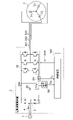
- FIG. 2 is a schematic wiring diagram showing the motor drive device 2 of the first embodiment together with the motor 7.
- the motor drive device 2 shown in FIG. 2, the motor 7, and the refrigeration cycle 900 shown in FIG. 1 constitute a refrigeration cycle device.
- the motor drive device 2 shown in FIG. 2 is for driving the motor 7, and includes a reactor 4, a rectifier circuit 10, a smoothing capacitor 20, an inverter 30, a voltage detection unit 82, and an input current detection unit. It has 84 and a control device 100.
- the rectifier circuit 10 converts the AC power supplied from the AC power supply 1 into DC power.
- the rectifier circuit 10 is composed of a diode bridge.
- the input terminal of the diode bridge is connected to the AC power supply 1 via the reactor 4, and the output terminal is connected to the smoothing capacitor 20.
- the smoothing capacitor 20 smoothes the output voltage of the rectifier circuit 10.
- One electrode (positive electrode) of the smoothing capacitor 20 is connected to the first output terminal of the rectifier circuit 10 and the DC bus 22a on the high potential side (positive side).
- the other electrode (negative electrode) of the smoothing capacitor 20 is connected to the second output terminal of the rectifier circuit 10 and the DC bus 22b on the low potential side (negative side).
- the inverter 30 receives a DC voltage between both electrodes of the smoothing capacitor 20, generates a three-phase AC voltage having a variable frequency and a variable voltage, and supplies the three-phase AC voltage to the motor 7 via the output lines 331 to 333.
- the DC voltage input to the inverter 30 is called the input voltage of the inverter, or simply the input voltage.
- the motor 7 is, for example, a three-phase permanent magnet synchronous motor.
- the voltage detection unit 82 detects the DC voltage Vdc between the DC bus 22a and 22b as the input voltage of the inverter.
- the voltage detection unit 82 includes, for example, a circuit that divides the input voltage Vdc by a resistance connected in series, and converts the input voltage Vdc into a voltage suitable for processing by the microcomputer in the control device 100, for example, a voltage of 5 V or less and outputs the voltage. ..
- This signal (voltage detection signal) is converted into a digital signal by an A / D conversion unit (not shown) in the control device 100 and used for internal processing of the control device 100.
- the input current detection unit 84 detects the input current Idc of the inverter 30.
- the input current detection unit 84 includes a shunt resistance inserted in the DC bus 22b between the negative electrode of the smoothing capacitor 20 and the inverter 30, and supplies an analog signal indicating the detection result to the control device 100.
- This signal (current detection signal) is converted into a digital signal by an A / D conversion unit (not shown) in the control device 100 and used for internal processing of the control device 100.
- control device 100 To control the inverter 30, the control device 100 generates PWM signals Sm1 to Sm6 and supplies them to the inverter 30.
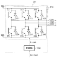
- the inverter 30 has an inverter main circuit 310 and a drive circuit 350, and the input terminal of the inverter main circuit 310 is connected to the DC bus 22a and 22b.
- the inverter main circuit 310 each has six arms including switching elements 311 to 316. Rectifying elements 321 to 326 for reflux are connected in antiparallel to the switching elements 311 to 316.
- the drive circuit 350 generates drive signals Sr1 to Sr6 based on the PWM signals Sm1 to Sm6, and controls the on / off of the switching elements 311 to 316 by the drive signals Sr1 to Sr6, whereby the frequency is variable and the voltage is variable.
- the three-phase AC voltage of No. 3 is applied to the motor 7 via the output lines 331 to 333.
- the drive signals Sr1 to Sr6 are voltage levels required to control the switching elements 311 to 316, for example. It is a signal having a magnitude of + 15V to -15V. Further, while the PWM signals Sm1 to Sm6 use the ground potential of the control device 100 as a reference potential, the drive signals Sr1 to Sr6 are the potentials of the negative terminals (emitter terminals) of the corresponding switching elements. Is the reference potential.
- the control device 100 controls the operation of the inverter 30 as described above. Specifically, the control device 100 controls the inverter 30 to change the frequency and the voltage value of the output voltage thereof.
- the angular frequency ⁇ of the output voltage of the inverter 30 determines the rotation angle speed at the electric angle of the motor 7 (represented by the same sign ⁇ as the angular frequency of the output voltage), and the rotation angle speed at the mechanical angle of the motor 7.
- ⁇ m is equal to the rotation angular frequency ⁇ at the electric angle of the motor 7 divided by the pole log number P m . Therefore, there is a relationship expressed by the following equation (1) between the rotation angular velocity ⁇ m at the mechanical angle of the motor 7 and the angular frequency ⁇ of the output voltage of the inverter 30.
- the angular velocity is simply referred to as the rotational velocity
- the angular frequency is sometimes referred to simply as the frequency.
- the control device 100 calculates the d-axis current Id and the q-axis current Iq of the rotational coordinate system based on the phase currents Iu, Iv, and Iw of the electric motor 7, and d based on the input voltage Vdc and the q-axis current Iq.
- Axis voltage command value d * is generated, and d-axis voltage command value Vd * and q-axis voltage are generated based on frequency command value ⁇ * , d-axis current command value Id * , d-axis current Id, and q-axis current Iq.
- the command value Vq * is generated, and PWM signals Sm1 to Sm6 for inverter control are generated based on the d-axis voltage command value Vd * and the q-axis voltage command value Vq * to control the inverter 30.
- the control device 100 is realized by a microprocessor.
- the microprocessor may be a processor or a processing device called a CPU (Central Processing Unit), a microcomputer, or a DSP (Digital Signal Processor).
- CPU Central Processing Unit
- microcomputer or a DSP (Digital Signal Processor).
- DSP Digital Signal Processor
- FIG. 4 is a functional block diagram showing an example of the control device 100. As shown in the figure, the control device 100 includes an operation control unit 102 and an inverter control unit 110.
- the operation control unit 102 outputs the frequency command value ⁇ * .
- the frequency command value ⁇ * is obtained by multiplying the command value (rotation angular velocity command value) ⁇ m * of the rotation speed of the motor 7 by the pole logarithm P m , as shown in the following equation (2).
- the operation control unit 102 receives information Qa indicating the room temperature (temperature of the air conditioning target space) detected by a temperature sensor (not shown), receives an instruction Qb from an operation unit (for example, a remote controller) (not shown), and operates each part of the air conditioner. To control.
- the instructions from the operation unit include information indicating the set temperature, selection of the operation mode (heating, cooling, dehumidification, etc.), and instructions for starting and ending the operation.
- the inverter control unit 110 includes a current restoration unit 111, a three-phase two-phase conversion unit 112, a d-axis current command value generation unit 114, a voltage command value generation unit 115, an electrical phase calculation unit 116, and a two-phase three-phase system. It has a conversion unit 117 and a PWM signal generation unit 118.
- the current restoration unit 111 restores the phase currents Iu, Iv, and Iw flowing through the motor 7 based on the input current Idc detected by the input current detection unit 84.
- the current restoration unit 111 samples the input current Idc detected by the input current detection unit 84 at a timing determined based on the PWM signals Sm1 to Sm6 from the PWM signal generation unit 118, whereby the phase currents Iu, Iv and Restore Iw.
- the three-phase two-phase conversion unit 112 uses the phase currents Iu, Iv, and Iw restored by the current restoration unit 111 as the d-axis current Id and the q-axis current using the electric phase ⁇ e generated by the electric phase calculation unit 116 described later. Convert to Iq.
- the d-axis current command value generation unit 114 is generated by the input voltage Vdc detected by the voltage detection unit 82, the q-axis current Iq obtained by conversion in the three-phase two-phase conversion unit 112, and the voltage command value generation unit 115.
- the d-axis current command value Id * is generated and output based on the d-axis voltage command value Vd * and the q-axis voltage command value Vq * .
- the voltage command value generation unit 115 has a d-axis current Id and a q-axis current Iq obtained from the 3-phase 2-phase conversion unit 112, a frequency command value ⁇ * output from the operation control unit 102, and a d-axis current command value.
- the d-axis current command value Id * obtained from the generation unit 114 and the input voltage Vdc detected by the voltage detection unit 82 are input, and the voltage command values Vd * and Vq * are generated and output based on these. ..
- the voltage command value generation unit 115 further estimates and outputs the estimated frequency value ⁇ est from the voltage command values Vd * and Vq * and the d-axis current Id and the q-axis current Iq.
- the voltage command value generation unit 115 operates in the first mode or the second mode.
- the voltage command value generation unit 115 normally operates in the first mode, and operates in the second mode during overmodulation. For example, it operates in the first mode until the modulation factor Fm for PWM control described later reaches the first threshold value Fmta, and when the modulation factor Fm becomes larger than the first threshold value Fmta, it switches to the second mode. Transition. When the modulation factor Fm becomes smaller than the second threshold value Fmtb during the operation in the second mode, the mode returns to the first mode.
- the second threshold value Fmtb may be the same as or smaller than the first threshold value Fmta.
- the method of generating the voltage command values Vd * and Vq * is different between the first mode and the second mode.
- the electric phase calculation unit 116 calculates the electric phase ⁇ e by integrating the estimated value ⁇ est of the frequency output from the voltage command value generation unit 115.
- the two-phase three-phase conversion unit 117 converts the d-axis voltage command value Vd * and the q-axis voltage command value Vq * (voltage command value of the two-phase coordinate system) obtained by the voltage command value generation unit 115 into the electrical phase calculation unit 116.
- the output voltage command value (3-phase voltage command value) of the 3-phase coordinate system is converted into Vu * , Vv * , and Vw * and output using the electric phase ⁇ e obtained in.
- the PWM signal generation unit 118 is a PWM signal based on the input voltage Vdc detected by the voltage detection unit 82 and the three-phase voltage command values Vu * , Vv * and Vw * obtained by the two-phase three-phase conversion unit 117. Generates and outputs Sm1 to Sm6.
- the two-phase three-phase conversion unit 117 and the PWM signal generation unit 118 constitute an inverter control signal generation unit 119.
- the inverter control signal generation unit 119 generates PWM signals Sm1 to Sm6 based on the d-axis voltage command value Vd * and the q-axis voltage command value Vq * .
- the d-axis current command value generation unit 114 has, for example, a weakening magnetic flux control unit 410 and a limiting circuit 420, as shown in FIG.
- the weakening magnetic flux control unit 410 generates a d-axis current value Id_fw * based on the input voltage Vdc and the voltage command values Vd * and Vq * .
- the d-axis current value Id_fw * is a d-axis current command value for weakening magnetic flux control.
- the weakening magnetic flux control unit 410 obtains the d-axis current value (d-axis current command value for weakening magnetic flux control) Id_fw * by the integral type weakening magnetic flux control.
- the weakening control magnetic flux control unit 410 has an amplitude calculation unit 411, a coefficient multiplication unit 412, a multiplication unit 413, and an integration unit 415.
- the amplitude calculation unit 411 calculates the amplitude Vdq * _abs * of the voltage command vector based on the voltage command values Vd * and Vq * obtained by the voltage command value generation unit 115 as described later.
- Vdq * _abs is calculated by the following equation (3).
- the coefficient multiplying unit 412 multiplies the input voltage Vdc by 1 / ⁇ 2.
- the multiplication unit 413 multiplies the output of the coefficient multiplication unit 412 by the above-mentioned first threshold value Fmta, and outputs the limit value Vom.
- the first threshold value Fmta is the modulation factor at which the weakening magnetic flux control is started.
- the subtraction unit 414 subtracts the amplitude Vdq * _abs from the limit value Vom to obtain the difference.
- the integrating unit 415 multiplies the difference obtained by the subtracting unit 414 by the coefficient Kifw, integrates the product, and generates the d-axis current value Id_fw * .
- the d-axis current value Id_fw * output from the integrating unit 415 is the output of the weakening magnetic flux control unit 410.
- the d-axis current value Id_fw * gradually increases in the negative direction when the amplitude Vdq * _abs of the voltage command vector is larger than the limit value Vom, and is negative when the amplitude Vdq * _abs of the voltage command vector is smaller than the limit value Vom. It gradually decreases in the direction (the absolute value gradually decreases).
- the limiting circuit 420 applies a limit using a limit value that defines an upper limit and a lower limit to the d-axis current value Id_fw * to generate a d-axis current command value Id * .
- the limiting circuit 420 has an MTPA control unit 421, a selection unit 422, and a limiter 423.
- the MTPA control unit 421 obtains the d-axis current command value Id_mtpa * , which is the most efficient for driving the motor 7, based on the q-axis current Iq.
- This d-axis current command value Id_mtpa * is also referred to as "current command value of maximum torque / current control (Maximum torque per ampere control)".
- the selection unit 422 selects and outputs the d-axis current command value Id_mtpa * and the d-axis current value Id_fw * , whichever is larger in the negative direction (the one whose value is negative and whose absolute value is larger).
- the limiter 423 performs limit processing on the output of the selection unit 422, and outputs the result of the limit processing as the d-axis current command value Id * .
- the limit processing in the limiter 423 applies a limit to the absolute value of the output of the selection unit 422 by using an upper limit value.
- the limitation using the upper limit value is performed in order to prevent the electric motor 7 from being demagnetized (irreversibly demagnetized) due to an excessive d-axis current command value Id * .
- the d-axis current command value Id * is the d-axis current command value.
- the value is not larger in the positive direction than that of Id_mtpa * . That is, it can be said that the MTPA control unit 421 and the selection unit 422 impose a positive restriction on the d-axis current command value Id * .
- zero may be set as the limit value in the positive direction.
- the MTPA control unit 421 is unnecessary, and a value zero may be input to the selection unit 422 instead of the d-axis current command value Id_mtpa * .
- the voltage command value generation unit 115 is configured as shown in FIG. 6, for example.
- the illustrated voltage command value generation unit 115 includes a frequency estimation unit 501, a subtraction unit 502, a speed control unit 503, a voltage value calculation unit 520, a modulation factor calculation unit 551, a correction coefficient generation unit 552, and a mode determination. It has a unit 553 and a multiplication unit 560.
- the frequency estimation unit 501 receives the d-axis current Id and q-axis current Iq output from the three-phase two-phase conversion unit 112 and the voltage command values Vd * and Vq * output from the multiplication unit 560 as inputs to these. Based on this, the frequency of the voltage applied to the motor 7 is estimated, and the estimated value ⁇ est is output.
- the speed control unit 503 performs a proportional integral (PI) operation on the calculated frequency deviation del_ ⁇ to obtain the q-axis current command value Iq * that brings the deviation close to zero.
- PI proportional integral
- control is performed to match the frequency estimation value ⁇ est with the frequency command value ⁇ * .
- the rotation speed of the electric motor 7 is proportional to the frequency of the AC voltage applied to the electric motor 7, so that the control by the speed control unit 503 makes the deviation of the speed estimation value with respect to the speed command value close to zero. It can be said that it is the control of.
- the speed control unit 503 has, for example, as shown in FIG. 7, a coefficient multiplication unit 5031 and 5032, an integration unit 5033, an addition unit 5034, and a limiter 5035.
- the coefficient multiplying unit 5031 multiplies the frequency deviation del_ ⁇ by a predetermined coefficient.
- the coefficient multiplying unit 5032 multiplies the frequency deviation del_ ⁇ by a predetermined coefficient.
- the coefficient used in the coefficient multiplying unit 5031 and the coefficient used in the coefficient multiplying unit 5032 may have the same value or different values.
- the integrating unit 5033 integrates the output of the coefficient multiplying unit 5032.
- the output of the coefficient multiplying unit 5031 is the result of the proportional operation with respect to the frequency deviation del_ ⁇
- the output of the integrating unit 5033 is the result of the integral operation with respect to the frequency deviation del_ ⁇ .
- the addition unit 5034 adds the output of the coefficient multiplication unit 5031 and the output of the integration unit 5033 to output the q-axis current value Iq1 * .
- the q-axis current value Iq1 * is the result of a proportional integral (PI) operation for the frequency deviation del_ ⁇ .
- the limiter 5035 imposes positive and negative restrictions on the q-axis current value Iq1 * .
- the output Iq * of the limiter 5035 is output from the speed control unit 503 as a q-axis current command value.
- the voltage value calculation unit 520 converts the d-axis current command value Id * output from the d-axis current command value generation unit 114, the q-axis current command value Iq * output from the speed control unit 503, and the three-phase two-phase conversion.
- the d-axis current Id and q-axis current Iq output from the unit 112, the frequency estimation value ⁇ est output from the frequency estimation unit 501, and the mode signal Ss output from the mode determination unit 553 are input to the d-axis voltage.
- the value Vd3 * and the q-axis voltage value Vq3 * are output.
- the voltage value calculation unit 520 has a d-axis voltage value calculation unit 521 and a q-axis voltage value calculation unit 522.
- the d-axis voltage value calculation unit 521 includes a subtraction unit 5210, a proportional calculation unit 5211, an integration calculation unit 5212, a d-axis compensation value calculation unit 5213, switches 5215 and 5216, and an addition unit 5217.
- the proportional calculation unit 5211 performs a proportional calculation on the d-axis current deviation del_Id to generate a first d-axis voltage value Vdfbp * as a result of the proportional calculation.
- the first d-axis voltage value Vdfbp * is supplied to the adder 5217 via the switch 5215.
- the integration calculation unit 5212 performs an integration calculation on the d-axis current deviation del_Id to generate a second d-axis voltage value Vdfbi * as a result of the integration calculation.
- the second d-axis voltage value Vdfbi * is supplied to the adder 5217 via the switch 5216.
- the d-axis compensation value calculation unit 5213 calculates the d-axis compensation value Vdf * based on the q-axis current command value Iq * and the frequency estimation value ⁇ est .
- the d-axis compensation value Vdff * is a compensation value for canceling the interference voltage generated on the d-axis by the q-axis current command value Iq * .
- the interference voltage generated on the d-axis by the q-axis current command value Iq * means the d-axis voltage induced by the q-axis current command value Iq * .
- the compensation value Vdf * is obtained by an operation represented by the formula (4a) described later.
- the d-axis compensation value Vdff * is supplied to the addition unit 5217.
- the addition unit 5217 adds the first d-axis voltage value Vdfbp * , the second d-axis voltage value Vdfbi * , and the d-axis compensation value Vdf * , and adds the addition result to the third d-axis voltage value Vd3 *. Is output as.
- the third d-axis voltage value Vd3 * has a character as a voltage command value.
- the q-axis voltage value calculation unit 522 includes a subtraction unit 5220, a proportional calculation unit 5221, an integration calculation unit 5222, a q-axis compensation value calculation unit 5223, switches 5225 and 5226, and an addition unit 5227.
- the proportional calculation unit 5221 performs a proportional calculation on the q-axis current deviation del_Iq to generate a first q-axis voltage value Vqfbp * as a result of the proportional calculation.
- the first q-axis voltage value Vqfbp * is supplied to the adder 5227 via the switch 5225.
- the integration calculation unit 5222 performs an integration calculation on the q-axis current deviation del_Iq to generate a second q-axis voltage value Vqfbi * as a result of the integration calculation.
- the second q-axis voltage value Vqfbi * is supplied to the adder 5227 via the switch 5226.
- the q-axis compensation value calculation unit 5223 calculates the q-axis compensation value Vqff * based on the d-axis current command value Id * and the frequency estimation value ⁇ est .
- the q-axis compensation value Vqff * is a compensation value for canceling the interference voltage generated on the q-axis by the d-axis current command value Id * .
- the interference voltage generated on the d-axis by the d-axis current command value Id * means the q-axis voltage induced by the d-axis current command value Id * .
- the compensation value Vqff * is obtained, for example, by an operation represented by the equation (4b) described later.
- the q-axis compensation value Vqff * is supplied to the addition unit 5227.
- the addition unit 5227 adds the first q-axis voltage value Vqfbp * , the second q-axis voltage value Vqfbi * , and the q-axis compensation value Vqff * , and adds the addition result to the third q-axis voltage value Vq3 *. Is output as.
- the third q-axis voltage value Vq3 * has a character as a voltage command value.
- Ld is the d-axis inductance of the motor 7.
- Lq is the q-axis inductance of the motor 7.
- ⁇ f is the interlinkage magnetic flux.
- ⁇ est is a frequency estimation value, and for example, a value estimated by the frequency estimation unit 501 is used.
- the frequency command value ⁇ * may be used instead of the frequency estimation value ⁇ est .
- control using the above compensation values Vdff * and Vqff * can be regarded as FF (feedforward) control.
- Control using the compensation value is also called non-interference control.
- the switches 5215, 5216, 5225 and 5226 open and close according to the mode represented by the mode signal Ss.
- the switches 5215, 5216, 5225 and 5226 are closed in the first mode.
- the voltage values Vd3 * and Vq * 3 are given by the following equations.
- the switches 5215, 5216, 5225 and 5226 are open in the second mode.
- the voltage values Vd3 * and Vq * 3 are given by the following equations.
- Vdf * and Vqff * dominate among the equations (5a) and (5b), so even if the mode is switched from the first mode to the second mode. , The voltage values Vd3 * and Vq3 * do not change significantly.
- the modulation factor calculation unit 551 calculates the modulation factor Fm based on the third d-axis voltage value Vd3 * , the third q-axis voltage value Vq3 * , and the input voltage Vdc.
- the modulation factor Fm is calculated by the following formula.
- the correction coefficient generation unit 552 generates the correction coefficient Kh based on the modulation factor Fm calculated by the modulation factor calculation unit 551.
- the correction coefficient generation unit 552 is composed of, for example, a conversion table.
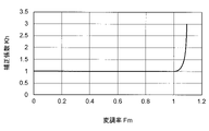
- FIG. 9 shows an example of the conversion characteristics of the conversion table.
- the correction coefficient Kh is 1 in the range where the modulation factor Fm is 1 or less, and the correction coefficient Kh is gradually larger than 1 in the range where the modulation factor Fm exceeds 1.
- the rate of increase in the correction coefficient Kh gradually increases as the modulation factor Fm increases.
- the mode determination unit 553 determines the operation mode based on the modulation factor Fm. For example, when the modulation factor Fm becomes larger than the first threshold value Fmta, the mode is switched from the first mode to the second mode, and when the modulation factor Fm becomes smaller than the second threshold value Fmtb, the second mode is changed to the second mode. Switch to mode 1.
- the second threshold value Fmtb may be the same as the first threshold value Fmta, or may be smaller than the first threshold value Fmta. For example, the first threshold Fmta is 1 and the second threshold Fmtb is 0.8.
- the mode signal Ss indicates the mode determined by the mode determination unit 553.
- the multiplication unit 560 multiplies the third d-axis voltage value Vd3 * and the third q-axis voltage value Vq3 * by the correction coefficient Kh.
- the multiplication result is output from the voltage command value generation unit 115 as a d-axis voltage command value and a q-axis voltage command value.
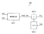
- the modulation factor calculation unit 551 includes, for example, an amplitude calculation unit 5511, a coefficient multiplication unit 5512, and a division unit 5513 as shown in FIG.
- the amplitude calculation unit 5511 obtains the square root of the sum of squares from the d-axis voltage value Vd3 * and the q-axis voltage value Vq3 * , and outputs the amplitude Vdq3 * _abs. This process is represented by the following equation (8).
- the coefficient multiplying unit 5512 multiplies the input voltage Vdc by a coefficient (1 / ⁇ 2).
- the division unit 5513 divides the output Vdq3 * _abs of the amplitude calculation unit 5511 by the output Vdc / ⁇ 2 of the coefficient multiplication unit 5512, and outputs the result of the division as the modulation factor (modulation factor before correction) Fm.
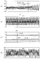
- FIG. 11A shows the speed. The speed shown is in units of "rps”.
- the reference numeral wref indicates a speed command value (corresponding to the frequency command value ⁇ * ), the reference numeral wr0 indicates an estimated speed (corresponding to the frequency estimated value ⁇ est ), and wr_mtr indicates an actual speed.
- FIG. 11B shows the torque. The torque shown is in units of "Nm”. The symbol Tem indicates the output torque of the motor 7, and the reference numeral Tl indicates the load torque.
- FIG. 11 (c) shows the current.
- the illustrated current is in units of "A".
- the reference numeral Id_ref indicates the d-axis current command value Id *
- the reference numeral Ides indicates the estimated value of the actual d-axis current
- the reference numeral Iq_ref indicates the q-axis current command value Iq *
- the reference numeral Iqes indicates the actual q-axis current.
- FIG. 11D shows an input voltage Vdc, with "V" as a unit.
- the operation in the first mode is performed until the modulation factor reaches 1, and when the modulation factor becomes larger than 1, (that is, in the overmodulation region), the operation in the second mode is performed. Do the action.
- PI control and non-interference control based on the current command value are performed.
- PI control is not performed, that is, only non-interference control is performed without using the result of PI calculation, and the compensation value generated as a result of non-interference control is the third d-axis voltage value Vd3 * and the third. It is output as the q-axis voltage value Vq3 * of 3, and the voltage command values Vd * and Vq * are generated based on the third d-axis voltage value Vd3 * and the third q-axis voltage value Vq3 * .
- the modulation factor Fm is obtained based on the voltage values Vd3 * and Vq3 *
- the correction coefficient Kh is generated based on the modulation factor Fm
- the voltage values Vd3 * and Vq3 * are multiplied by the correction coefficient Kh.
- Voltage command values Vd * and Vq * are generated, and the voltage command values Vd * and Vq * are supplied to the inverter control signal generation unit 119.
- the voltage values Vd3 * and Vq3 * have characteristics as voltage command values before correction. Therefore, it can be said that the process of multiplying the voltage values Vd3 * and Vq3 * by the correction coefficient Kh is the process of correcting the voltage command value.
- the relationship between the modulation factor and the correction coefficient is shown in FIG. 9.
- the ratio of the increase in the voltage actually output to the increase in the modulation factor increases with the increase in the modulation factor, as shown in FIG. It tends to become smaller and smaller, in other words, it has the characteristic that the output voltage saturates with the increase in the modulation factor. That is, the rate of increase in the correction coefficient is gradually increased as the modulation factor is increased so as to cancel such a tendency, that is, the saturation characteristic.
- the correction of the voltage command value by the correction coefficient can be regarded as the correction of the modulation factor.
- FIG. 13 shows changes in the voltage command vector due to multiplication of correction coefficients (modulation rate correction).
- the vector V3 * (Vd3 * , Vq3 * ) corresponding to the voltage values Vd3 * and Vq3 * output from the voltage value calculation unit 520 has a radius of ⁇ (2/3) ⁇ Vdc.
- the modulation factor increases only up to about ⁇ (2/3) / 1 / ⁇ 2 ⁇ 1.15.
- FIGS. 14 (a) to 14 (d) Changes in current and the like due to not using the result of PI control are as shown in FIGS. 14 (a) to 14 (d), for example.
- FIG. 14 (a) shows the speed. The speed shown is in units of "rps”.
- the reference numeral wref indicates a speed command value (corresponding to the frequency command value ⁇ * )
- the reference numeral wr0 indicates an estimated speed (corresponding to the frequency estimated value ⁇ est )
- wr_mtr indicates an actual speed.
- FIG. 14B shows the torque.
- the torque shown is in units of "Nm”.
- the symbol Tem indicates the output torque of the motor 7, and the reference numeral Tl indicates the load torque.
- FIG. 14 (c) shows the current.
- the illustrated current is in units of "A".
- the reference numeral Id_ref indicates the d-axis current command value Id *
- the reference numeral Ides indicates the actual d-axis current
- the reference numeral Iq_ref indicates the q-axis current command value Iq *
- the reference numeral Iqes indicates the estimated value of the actual q-axis current. Is shown.
- FIG. 14D shows an input voltage Vdc, with "V" as a unit.
- the limit value used in the second mode is set to be larger than the limit value used in the first mode. do. The reason for doing so will be described below.
- the compensation values Vdff * and Vqff * represented by the equations (4a) and (4b) are the voltage values Vd3 * and It becomes Vq3 *
- the voltage command values Vd * and Vq * are determined by the voltage values Vd3 * and Vq3 * .
- the compensation values Vdff * and Vqff * are the output (Iq * ) of the speed control unit 503 and the output of the d-axis current command value generation unit 114 including the weakening magnetic flux control unit 410. It is determined by (Id * ) and does not depend on the outputs of the proportional calculation units 5211 and 5221 and the integral calculation units 5212 and 5222.
- the voltage command value Vd * does not include a voltage component for reducing the difference between the d-axis current command value and the actual d-axis current
- the voltage command value Vq * includes the q-axis current command value and the actual q-axis. It does not include a voltage component to reduce the current difference. Therefore, if the constant of the motor used in the calculation for control and the actual constant of the motor are different, the deviation of the actual current with respect to the current command value may not approach zero.
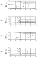
- FIGS. 15A and 15B show waveforms when the value of the d-axis inductance Ld used in the control is different from the actual value of the d-axis inductance.
- 15 (a) and 15 (b) show the case where the value of the d-axis inductance Ld used in the control is 0.8 times the actual value. In this case, the d-axis current command value Id * becomes larger in the negative direction than the actual current Id due to the weak magnetic flux control.
- 15 (c) and 15 (d) show the case where the value of the d-axis inductance Ld used in the control is 1.2 times the actual value. In this case, the d-axis current command value Id * becomes smaller in the negative direction than the actual current Id due to the weak magnetic flux control.
- the limit value of the current command value is set relatively large.
- the limit value Idlim of the d-axis current command value Id * output from the d-axis current command value generation unit 114 may be defined as the equation (9) based on the voltage equation.
- Km is a coefficient
- the d-axis current command value and the actual d-axis current do not match as shown in FIG. 15 (a), and are calculated based on the d-axis current command value Id * . Since it is controlled by the compensation value Vqff * , it may operate stably with a d-axis current command value Id * equal to the limit value Idlim when the coefficient Km in the equation (9) is larger than 1.
- the limit value of the d-axis current command value Id * is, for example, the maximum value of the absolute value of the estimated deviation (deviation del_Id of the actual current Id with respect to the d-axis current command value Id * ), and the first mode (modulation rate is It is preferable to set the absolute value to a value larger than the limit value used in (1 or less).
- the limit value may be set so that the absolute value is about 1.2 times larger than the limit value used in the first mode.
- the mode signal Ss is input to the limiter 423, and the limiter 423 limits according to the mode signal Ss. You may switch the value.
- the first mode (modulation rate is 1 or less) is the maximum value of the absolute value of del_Iq, which is the estimated deviation (deviation of the actual current Iq with respect to the q-axis current command value Iq * ). It is preferable to set the absolute value to a value larger than the limit value used in). Alternatively, the limit value may be set so that the absolute value is about 1.2 times larger than the limit value used in the first mode.
- the limit value for the q-axis current command value Iq * is set, for example, in the limiter 5035 of FIG.
- a mode signal Ss is input to the limiter 5035, and the limiter 5035 sets the limit value according to the mode signal Ss. It may be switched.
- the current command value may be set to a larger value.
- the value of the coefficient Kifw used in the integration unit 415 of FIG. 5 may be made larger.
- the mode signal Ss is input to the integrating unit 415, and the integrating unit 415 is used as the mode signal Ss.
- the value of the coefficient Kifw may be switched accordingly.
- the value of the coefficient multiplied by the coefficient multiplication units 5031 and 5032 in FIG. 7 may be made larger.
- the mode signal Ss is input to the coefficient multiplication unit 5031 and the coefficient multiplication unit 5032, and the coefficient multiplication unit 5031 and The coefficient multiplication unit 5032 may switch the value of each coefficient according to the mode signal Ss.
- the outputs of the proportional calculation units 5211 and 5221 and the outputs of the integral calculation units 5212 and 5222 are not used, but the outputs of the proportional calculation units 5211 and 5221 are used, and the integral calculation units 5212 and The output of 5222 may not be used.
- the voltage values Vd3 * and Vq3 * are given by the following equations (10a) and (10b).
- the weakening magnetic flux control unit 410 obtains the d-axis current command value Id_fw * by the integral type weakening magnetic flux control, but instead, it is calculated by the following equation (11) based on the voltage equation. May be.
- the Vom is a limit value and can be calculated in the same manner as described with respect to the coefficient multiplication unit 412 and the multiplication unit 413 shown in FIG. ⁇ is the frequency of the output voltage of the inverter 30.
- phase currents Iu, Iv and Iw are restored from the input current Idc of the inverter 30.
- a current detector may be provided on the output lines 331, 332, and 333 of the inverter 30, and the detector may be used to detect the phase current.
- the current detected by the above current detector may be used instead of the current restored by the current restoration unit 111.
- the switching elements 311 to 316 of the inverter main circuit 310 an IGBT (Insulated Gate Bipolar Transistor) or MOSFET is assumed, but any element capable of switching may be used. .. Since the MOSFET has a parasitic diode due to its structure, the same effect can be obtained without connecting the rectifying elements (321 to 326) for circulation in antiparallel.
- the materials constituting the switching elements 311 to 316 are made of not only silicon (Si) but also silicon carbide (SiC), gallium nitride (GaN), diamond, etc., which are wide bandgap semiconductors. It is possible to reduce the loss.
- the configuration shown in the above embodiments is an example of the configuration of the present invention, and can be combined with another known technique, and a part thereof is omitted as long as the gist of the present invention is not deviated. It is also possible to change and configure it.
- the motor drive device and the refrigeration cycle device equipped with the motor drive device have been described above.
- the refrigerating cycle device is used for an air conditioner
- the refrigerating cycle device may be used for a refrigerator, a freezer, a heat pump water heater, or the like.
Landscapes
- Engineering & Computer Science (AREA)
- Power Engineering (AREA)
- Mechanical Engineering (AREA)
- General Engineering & Computer Science (AREA)
- Physics & Mathematics (AREA)
- Thermal Sciences (AREA)
- Chemical & Material Sciences (AREA)
- Combustion & Propulsion (AREA)
- Control Of Ac Motors In General (AREA)
Abstract
Description
また、上記の適用において、省エネルギー化のため、低速回転域(軽負荷)における高効率化が求められるとともに、高速回転域(高負荷)における駆動範囲の拡大も求められている。
周波数可変で電圧値可変の交流電圧を生成し、電動機に印加するインバータと、
前記インバータを制御する制御装置とを備え、
前記制御装置は、
前記交流電圧の周波数の、周波数指令値に対する差分である周波数偏差に基づいてq軸電流指令値を生成し、
前記電動機のd軸電流のd軸電流指令値に対する差分であるd軸電流偏差に対して比例演算を行なって第1のd軸電圧値を生成し、
前記d軸電流偏差に対して積分演算を行なって第2のd軸電圧値を生成し、
前記q軸電流指令値により誘起されるd軸電圧を補償するd軸補償値を算出し、
前記電動機のq軸電流の前記q軸電流指令値に対する差分であるq軸電流偏差に対して比例演算を行なって第1のq軸電圧値を生成し、
前記q軸電流偏差に対して積分演算を行なって第2のq軸電圧値を生成し、
前記d軸電流指令値により誘起されるq軸電圧を補償するq軸補償値を算出し、
第1のモードでは、
前記第1のd軸電圧値と、前記第2のd軸電圧値と、前記d軸補償値とを用いて第3のd軸電圧値を生成し、
前記第1のq軸電圧値と、前記第2のq軸電圧値と、前記q軸補償値とを用いて第3のq軸電圧値を生成し、
第2のモードでは、
前記第1のd軸電圧値、前記第2のd軸電圧値、及び前記d軸補償値のうちの、少なくとも前記d軸補償値を用い、かつ前記第2のd軸電圧値を用いずに、前記第3のd軸電圧値を生成し、
前記第1のq軸電圧値、前記第2のq軸電圧値、及び前記q軸補償値のうちの、少なくとも前記q軸補償値を用い、かつ前記第2のq軸電圧値を用いずに、前記第3のq軸電圧値を生成し、
前記第3のd軸電圧値及び前記第3のq軸電圧値に基づいて変調率を算出し、
前記変調率に基づいて補正係数を生成し、
前記第3のd軸電圧値及び前記第3のq軸電圧値に対して前記補正係数を乗算して、d軸電圧指令値及びq軸電圧指令値を生成し、
前記d軸電圧指令値及び前記q軸電圧指令値に基づいて前記インバータをPWM制御する信号を生成し、
前記補正係数は、前記第1のモードでは1に維持され、
前記補正係数は、前記第2のモードでは、前記交流電圧が前記第3のd軸電圧値及び前記第3のq軸電圧値に相当する大きさとなるように定められる。
電動機駆動装置は、例えば空気調和機の冷凍サイクル装置の圧縮機の電動機を駆動するためのものである。
図1の冷凍サイクル900は四方弁902の切替動作により暖房運転又は冷房運転をすることができる。
冷房運転時には、破線矢印で示すように、冷媒が圧縮機904で加圧されて送り出され、四方弁902、室外熱交換器910、膨張弁908、室内熱交換器906及び四方弁902を通って圧縮機904に戻る。
圧縮機904は可変速制御される電動機7によって駆動される。
図2に示される電動機駆動装置2は、電動機7を駆動するためのものであり、リアクタ4と、整流回路10と、平滑コンデンサ20と、インバータ30と、電圧検出部82と、入力電流検出部84と、制御装置100とを有する。
平滑コンデンサ20の一方の電極(正電極)は、整流回路10の第1の出力端子及び高電位側(正側)の直流母線22aに接続されている。
平滑コンデンサ20の他方の電極(負電極)は、整流回路10の第2の出力端子及び低電位側(負側)の直流母線22bに接続されている。
電動機7は、例えば、3相永久磁石同期電動機である。
具体的には、制御装置100は、インバータ30を制御してその出力電圧の周波数及び電圧値を変化させる。


電圧指令値生成部115はさらに、電圧指令値Vd*及びVq*並びにd軸電流Id及びq軸電流Iqから周波数の推定値ωestを推定して出力する。
インバータ制御信号生成部119は、d軸電圧指令値Vd*及びq軸電圧指令値Vq*に基づいてPWM信号Sm1~Sm6を生成する。
弱め磁束制御部410は、入力電圧Vdc、並びに電圧指令値Vd*及びVq*に基づいてd軸電流値Id_fw*を生成する。d軸電流値Id_fw*は弱め磁束制御のためのd軸電流指令値である。
弱め磁束制御部410は、積分型の弱め磁束制御によりd軸電流値(弱め磁束制御のためのd軸電流指令値)Id_fw*を求める。

乗算部413は、係数乗算部412の出力に上記の第1の閾値Fmtaを乗算し、制限値Vomを出力する。第1の閾値Fmtaは弱め磁束制御が開始される変調率である。
減算部414は、制限値Vomから振幅Vdq*_absを減算し差分を求める。
積分部415から出力されるd軸電流値Id_fw*は、弱め磁束制御部410の出力となる。
d軸電流値Id_fw*は、電圧指令ベクトルの振幅Vdq*_absが制限値Vomよりも大きい場合は負方向に次第に大きくなり、電圧指令ベクトルの振幅Vdq*_absが制限値Vomよりも小さい場合は負方向に次第に小さくなる(絶対値が次第に小さくなる)。
制限回路420は、MTPA制御部421と、選択部422と、リミッタ423とを有する。
このd軸電流指令値Id_mtpa*は、「最大トルク/電流制御(Maximum torque per ampere control)の電流指令値」とも呼ばれるものである。
上限値を用いた制限は、d軸電流指令値Id*が過大になって、電動機7が減磁(不可逆的減磁)するのを防ぐために行われる。
なお、上記のように電動機7の回転速度は、電動機7に印加される交流電圧の周波数に比例するので、速度制御部503による制御は、速度指令値に対する速度推定値の偏差をゼロに近付けるための制御であると言える。
積分部5033は、係数乗算部5032の出力を積分する。
係数乗算部5031の出力は周波数偏差del_ωに対する比例演算の結果であり、積分部5033の出力は、周波数偏差del_ωに対する積分演算の結果である。
リミッタ5035は、q軸電流値Iq1*に対して、正方向及び負方向の制限を加える。リミッタ5035の出力Iq*がq軸電流指令値として速度制御部503から出力される。
積分演算部5212は、d軸電流偏差del_Idに対して積分演算を行って、積分演算の結果としての第2のd軸電圧値Vdfbi*を生成する。第2のd軸電圧値Vdfbi*は開閉器5216を介して加算部5217に供給される。
積分演算部5222は、q軸電流偏差del_Iqに対して積分演算を行って、積分演算の結果としての第2のq軸電圧値Vqfbi*を生成する。第2のq軸電圧値Vqfbi*は開閉器5226を介して加算部5227に供給される。

Ldは電動機7のd軸インダクタンス、
Lqは電動機7のq軸インダクタンス、
φfは鎖交磁束である。
d軸インダクタンスLd、q軸インダクタンスLq及び鎖交磁束φfの値は、予め求められ、例えば電圧値算出部520内に記憶されている。
なお、周波数推定値ωestの代わりに、周波数指令値ω*を用いても良い。
開閉器5215、5216、5225及び5226は、第1のモードでは閉じている。この場合、電圧値Vd3*及びVq*3は、下記の式で与えられる。


変調率Fmは下記の式で算出される。

補正係数生成部552は、例えば変換テーブルで構成されている。
変換テーブルの変換特性の一例を図9に示す。図9に示される変換特性では、変調率Fmが1以下の範囲では、補正係数Khは1であり、変調率Fmが1を超える範囲では、補正係数Khが1より次第に大きくなる。補正係数Khの増加の割合は、変調率Fmの増加に伴って次第に大きくなる。
振幅算出部5511は、d軸電圧値Vd3*及びq軸電圧値Vq3*からそれらの2乗和の平方根を求め、振幅Vdq3*_absとして出力する。この処理は、下記の式(8)で表される。

除算部5513は、振幅算出部5511の出力Vdq3*_absを係数乗算部5512の出力Vdc/√2で除算し、除算の結果を変調率(補正前の変調率)Fmとして出力する。
上記のように、一般的に過変調領域で電流をPI制御すると、積分項が飽和するワインドアップ現象が起きてしまい、電流制御系が不安定になる。これは、過変調領域では、電圧指令値に対する、実際に電動機7に印加される電圧の誤差が大きくなり、積分項が次第に大きくなるためである。
図11(a)は、速度を示す。図示の速度は「rps」を単位とする。符号wrefは、速度指令値(周波数指令値ω*に対応する)を示し、符号wr0は推定速度(周波数推定値ωestに対応する)を示し、wr_mtrは実速度を示す。
図11(b)は、トルクを示す。図示のトルクは「Nm」を単位とする。符号Temは電動機7の出力トルクを示し、符号Tlは負荷トルクを示す。
図11(d)は、入力電圧Vdcを示し、「V」を単位とする。
第1のモードでは、電流指令値に基づくPI制御と非干渉制御とを行なう。
上記のように、電圧値Vd3*及びVq3*は補正前の電圧指令値としての性格を持つ。従って、電圧値Vd3*及びVq3*に補正係数Khを乗算する処理は、電圧指令値を補正する処理であると言える。
変調率補正が無い場合、電圧値算出部520から出力される電圧値Vd3*及びVq3*に対応するベクトルV3*(Vd3*,Vq3*)は、半径が√(2/3)・Vdcである円周上に頂点がある六角形の内側に限定される。
従って、変調率は、最大でも√(2/3)/1/√2≒1.15程度までしか大きくならない。
即ち、電圧指令値の補正(変調率の補正)を行うことで、過変調領域でも電圧値(補正前の電圧指令値)Vd3*,Vq3*に相当する値の電圧を電動機7に印加することができ、安定した動作が可能となる。
図14(a)は、速度を示す。図示の速度は「rps」を単位とする。符号wrefは、速度指令値(周波数指令値ω*に対応する)を示し、符号wr0は推定速度(周波数推定値ωestに対応する)を示し、wr_mtrは実速度を示す。
図14(b)は、トルクを示す。図示のトルクは「Nm」を単位とする。符号Temは電動機7の出力トルクを示し、符号Tlは負荷トルクを示す。
図14(d)は、入力電圧Vdcを示し、「V」を単位とする。
以下そのようにする理由について説明する。
そのため、制御のための演算で用いている電動機の定数と、電動機の実際の定数が異なる場合、電流指令値に対する実電流の偏差がゼロに近づかない可能性がある。
図15(a)及び(b)は、制御で用いられたd軸インダクタンスLdの値が実際の値の0.8倍である場合を示す。この場合、弱め磁束制御によりd軸電流指令値Id*が実電流Idに比べ負方向に大きくなる。
図15(c)及び(d)は、制御で用いられたd軸インダクタンスLdの値が実際の値の1.2倍である場合を示す。この場合、弱め磁束制御によりd軸電流指令値Id*が実電流Idに比べ負方向に小さくなる。
例えば、d軸電流指令値生成部114から出力されるd軸電流指令値Id*のリミット値Idlimは、電圧方程式に基づき式(9)のように定義されることもある。

そのためd軸電流指令値Id*のリミット値は例えば、推定される偏差(d軸電流指令値Id*に対する実電流Idの偏差del_Id)の絶対値の最大値だけ、第1のモード(変調率が1以下であるとき)で用いられるリミット値より絶対値を大きくした値に設定するのが好ましい。
第1のモードと第2のモードとで異なる値のリミット値を用いるには、例えば、図5に示すように、モード信号Ssをリミッタ423に入力し、リミッタ423がモード信号Ssに応じてリミット値を切替えることとしても良い。
代わりに、第1のモードで用いられるリミット値に比べその絶対値が1.2倍程度に大きくなるようにリミット値を設定しても良い。
第1のモードと第2のモードとで異なるリミット値を用いるには、例えば、図7に示すように、モード信号Ssをリミッタ5035に入力し、リミッタ5035がモード信号Ssに応じてリミット値を切替えることとしても良い。
d軸電流指令値Id*をより大きくするには、例えばd軸電流指令値生成部114において、図5の積分部415で用いられる係数Kifwの値をより大きくしても良い。
この場合、電圧値Vd3*及びVq3*は下記の式(10a)及び(10b)で与えられる。


Vomは、制限値であり、図5に示される係数乗算部412及び乗算部413に関して説明したのと同様に算出され得る。
ωは、インバータ30の出力電圧の周波数である。
Claims (18)
- 周波数可変で電圧値可変の交流電圧を生成し、電動機に印加するインバータと、
前記インバータを制御する制御装置とを備え、
前記制御装置は、
前記交流電圧の周波数の、周波数指令値に対する差分である周波数偏差に基づいてq軸電流指令値を生成し、
前記電動機のd軸電流のd軸電流指令値に対する差分であるd軸電流偏差に対して比例演算を行なって第1のd軸電圧値を生成し、
前記d軸電流偏差に対して積分演算を行なって第2のd軸電圧値を生成し、
前記q軸電流指令値により誘起されるd軸電圧を補償するd軸補償値を算出し、
前記電動機のq軸電流の前記q軸電流指令値に対する差分であるq軸電流偏差に対して比例演算を行なって第1のq軸電圧値を生成し、
前記q軸電流偏差に対して積分演算を行なって第2のq軸電圧値を生成し、
前記d軸電流指令値により誘起されるq軸電圧を補償するq軸補償値を算出し、
第1のモードでは、
前記第1のd軸電圧値と、前記第2のd軸電圧値と、前記d軸補償値とを用いて第3のd軸電圧値を生成し、
前記第1のq軸電圧値と、前記第2のq軸電圧値と、前記q軸補償値とを用いて第3のq軸電圧値を生成し、
第2のモードでは、
前記第1のd軸電圧値、前記第2のd軸電圧値、及び前記d軸補償値のうちの、少なくとも前記d軸補償値を用い、かつ前記第2のd軸電圧値を用いずに、前記第3のd軸電圧値を生成し、
前記第1のq軸電圧値、前記第2のq軸電圧値、及び前記q軸補償値のうちの、少なくとも前記q軸補償値を用い、かつ前記第2のq軸電圧値を用いずに、前記第3のq軸電圧値を生成し、
前記第3のd軸電圧値及び前記第3のq軸電圧値に基づいて変調率を算出し、
前記変調率に基づいて補正係数を生成し、
前記第3のd軸電圧値及び前記第3のq軸電圧値に対して前記補正係数を乗算して、d軸電圧指令値及びq軸電圧指令値を生成し、
前記d軸電圧指令値及び前記q軸電圧指令値に基づいて前記インバータをPWM制御する信号を生成し、
前記補正係数は、前記第1のモードでは1に維持され、
前記補正係数は、前記第2のモードでは、前記交流電圧が前記第3のd軸電圧値及び前記第3のq軸電圧値に相当する大きさとなるように定められる
電動機駆動装置。 - 前記制御装置は、
前記第1のモードでは、
前記第1のd軸電圧値と、前記第2のd軸電圧値と、前記d軸補償値とを加算することで、前記第3のq軸電圧値を生成し、
前記第1のq軸電圧値と、前記第2のq軸電圧値と、前記q軸補償値とを加算することで、前記第3のq軸電圧値を生成する
請求項1に記載の電動機駆動装置。 - 前記第2のモードでは、
前記第1のd軸電圧値と前記d軸補償値とを加算することで前記第3のd軸電圧値を生成し、
前記第1のq軸電圧値と前記q軸補償値とを加算することで前記第3のq軸電圧値を生成する
請求項2に記載の電動機駆動装置。 - 前記第2のモードでは、
前記d軸補償値を前記第3のd軸電圧値として用い、
前記q軸補償値を前記第3のq軸電圧値として用いる
請求項2に記載の電動機駆動装置。 - 前記第2のモードでは、前記変調率が大きくなるほど、前記変調率の増加に対する前記補正係数の増加がより大きくなるように、前記補正係数が定められる
請求項1から4のいずれか1項に記載の電動機駆動装置。 - 前記第2のモードでは、前記変調率の増加に対して、前記交流電圧が飽和する特性を打ち消すように前記補正係数が定められる
請求項1から4のいずれか1項に記載の電動機駆動装置。 - 前記制御装置は、
前記変調率が第1の閾値よりも大きくなったら前記第1のモードを選択し、
前記変調率が前記第1の閾値以下である第2の閾値よりも小さくなったら前記第2のモードを選択する
請求項1から6のいずれか1項に記載の電動機駆動装置。 - 前記制御装置は、
前記インバータの入力電圧と、前記d軸電圧指令値と、前記q軸電圧指令値とに基づいて、d軸電流値を算出し、
前記d軸電流値の絶対値に対してリミット値を用いて制限を加えることで前記d軸電流指令値を生成する
請求項1から7のいずれか1項に記載の電動機駆動装置。 - 前記第1のモードで用いられるリミット値よりも前記第2のモードで用いられるリミット値の方が大きい
請求項8に記載の電動機駆動装置。 - 前記第2のモードで用いられる前記リミット値は、前記第1のモードで用いられる前記リミット値に対し、前記d軸電流偏差の推定値の最大値だけ大きい
請求項9に記載の電動機駆動装置。 - 前記第1のモードで算出される前記d軸電流値よりも前記第2のモードで算出される前記d軸電流値の方が大きい
請求項8に記載の電動機駆動装置。 - 前記第2のモードで算出される前記d軸電流値は、前記第1のモードで算出される前記d軸電流値よりも予め定められた1より大きい係数を掛けた値となるように算出される
請求項11に記載の電動機駆動装置。 - 前記制御装置は、
前記周波数偏差に対して比例積分演算を行なって、q軸電流値を生成し、
前記q軸電流値の絶対値に対してリミット値を用いて制限を加えることで前記q軸電流指令値を生成し、
前記第1のモードで用いられるリミット値よりも前記第2のモードで用いられるリミット値の方が大きい
請求項1から6のいずれか1項に記載の電動機駆動装置。 - 前記第2のモードで用いられる前記リミット値は、前記第1のモードで用いられる前記リミット値に対し、前記q軸電流偏差の推定値の最大値だけ大きい
請求項9に記載の電動機駆動装置。 - 前記第1のモードで生成される前記q軸電流指令値よりも前記第2のモードで生成される前記q軸電流指令値の方が大きい
請求項1から12のいずれか1項に記載の電動機駆動装置。 - 前記第2のモードで生成される前記q軸電流指令値は、前記第1のモードで生成されるq軸電流指令値に対し予め定められた1より大きい係数を掛けた値となるように算出される
請求項15に記載の電動機駆動装置。 - 請求項1から16のいずれか1項に記載の電動機駆動装置を備えた冷凍サイクル装置。
- 請求項17に記載の冷凍サイクル装置を備えた空気調和機。
Priority Applications (4)
| Application Number | Priority Date | Filing Date | Title |
|---|---|---|---|
| CN202080107700.4A CN116547903A (zh) | 2020-12-17 | 2020-12-17 | 电动机驱动装置、制冷循环装置和空调机 |
| US18/249,079 US20230402946A1 (en) | 2020-12-17 | 2020-12-17 | Motor driving apparatus, refrigeration cycle equipment, and air conditioner |
| PCT/JP2020/047186 WO2022130571A1 (ja) | 2020-12-17 | 2020-12-17 | 電動機駆動装置、冷凍サイクル装置、及び空気調和機 |
| JP2022569428A JP7361948B2 (ja) | 2020-12-17 | 2020-12-17 | 電動機駆動装置、冷凍サイクル装置、及び空気調和機 |
Applications Claiming Priority (1)
| Application Number | Priority Date | Filing Date | Title |
|---|---|---|---|
| PCT/JP2020/047186 WO2022130571A1 (ja) | 2020-12-17 | 2020-12-17 | 電動機駆動装置、冷凍サイクル装置、及び空気調和機 |
Publications (1)
| Publication Number | Publication Date |
|---|---|
| WO2022130571A1 true WO2022130571A1 (ja) | 2022-06-23 |
Family
ID=82057415
Family Applications (1)
| Application Number | Title | Priority Date | Filing Date |
|---|---|---|---|
| PCT/JP2020/047186 Ceased WO2022130571A1 (ja) | 2020-12-17 | 2020-12-17 | 電動機駆動装置、冷凍サイクル装置、及び空気調和機 |
Country Status (4)
| Country | Link |
|---|---|
| US (1) | US20230402946A1 (ja) |
| JP (1) | JP7361948B2 (ja) |
| CN (1) | CN116547903A (ja) |
| WO (1) | WO2022130571A1 (ja) |
Citations (4)
| Publication number | Priority date | Publication date | Assignee | Title |
|---|---|---|---|---|
| JP2006020411A (ja) * | 2004-07-01 | 2006-01-19 | Hitachi Ltd | 永久磁石同期電動機の制御装置及びモジュール |
| JP2007116791A (ja) * | 2005-10-19 | 2007-05-10 | Hitachi Ltd | 永久磁石同期電動機の弱め界磁ベクトル制御装置及びモジュール |
| JP2011091976A (ja) * | 2009-10-26 | 2011-05-06 | Hitachi Industrial Equipment Systems Co Ltd | モータ制御装置、及びモータ制御システム |
| JP2020031485A (ja) * | 2018-08-22 | 2020-02-27 | サンデンホールディングス株式会社 | 電力変換装置 |
Family Cites Families (4)
| Publication number | Priority date | Publication date | Assignee | Title |
|---|---|---|---|---|
| JP4466600B2 (ja) * | 2006-03-31 | 2010-05-26 | アイシン・エィ・ダブリュ株式会社 | 電動駆動制御装置及び電動駆動制御方法 |
| WO2008152929A1 (ja) * | 2007-06-12 | 2008-12-18 | Kabushiki Kaisha Yaskawa Denki | モータ制御装置とその制御方法 |
| JP4329880B1 (ja) * | 2009-01-14 | 2009-09-09 | トヨタ自動車株式会社 | 交流電動機の制御装置および電動車両 |
| CN105103434B (zh) * | 2013-04-10 | 2016-09-28 | 三菱电机株式会社 | 永磁体型电动机的控制装置 |
-
2020
- 2020-12-17 JP JP2022569428A patent/JP7361948B2/ja active Active
- 2020-12-17 US US18/249,079 patent/US20230402946A1/en not_active Abandoned
- 2020-12-17 WO PCT/JP2020/047186 patent/WO2022130571A1/ja not_active Ceased
- 2020-12-17 CN CN202080107700.4A patent/CN116547903A/zh active Pending
Patent Citations (4)
| Publication number | Priority date | Publication date | Assignee | Title |
|---|---|---|---|---|
| JP2006020411A (ja) * | 2004-07-01 | 2006-01-19 | Hitachi Ltd | 永久磁石同期電動機の制御装置及びモジュール |
| JP2007116791A (ja) * | 2005-10-19 | 2007-05-10 | Hitachi Ltd | 永久磁石同期電動機の弱め界磁ベクトル制御装置及びモジュール |
| JP2011091976A (ja) * | 2009-10-26 | 2011-05-06 | Hitachi Industrial Equipment Systems Co Ltd | モータ制御装置、及びモータ制御システム |
| JP2020031485A (ja) * | 2018-08-22 | 2020-02-27 | サンデンホールディングス株式会社 | 電力変換装置 |
Also Published As
| Publication number | Publication date |
|---|---|
| JP7361948B2 (ja) | 2023-10-16 |
| US20230402946A1 (en) | 2023-12-14 |
| CN116547903A (zh) | 2023-08-04 |
| JPWO2022130571A1 (ja) | 2022-06-23 |
Similar Documents
| Publication | Publication Date | Title |
|---|---|---|
| JP2002247876A (ja) | インバータ装置、圧縮機制御装置、冷凍・空調装置の制御装置、モータの制御方法、圧縮機、冷凍・空調装置 | |
| US20240372498A1 (en) | Power converter, motor drive device, and refrigeration cycle application apparatus | |
| US10270380B2 (en) | Power converting apparatus and heat pump device | |
| JP2014087223A (ja) | ベクトル制御装置、およびそれを用いたモータ制御装置、空調機 | |
| JP7566175B2 (ja) | 電力変換装置、電動機駆動装置及び冷凍サイクル適用機器 | |
| CN118140404A (zh) | 电力转换装置、马达驱动装置和制冷循环应用设备 | |
| JP6982532B2 (ja) | 冷凍サイクル装置 | |
| JP2009273302A (ja) | 電動モータの制御装置 | |
| JP7237746B2 (ja) | オープン巻線モータ駆動装置及び冷凍サイクル装置 | |
| WO2025069183A1 (ja) | 電力変換装置、電動機駆動装置及び冷凍サイクル適用機器 | |
| JP7566174B2 (ja) | 電力変換装置、電動機駆動装置及び冷凍サイクル適用機器 | |
| JP7361948B2 (ja) | 電動機駆動装置、冷凍サイクル装置、及び空気調和機 | |
| US11264924B2 (en) | Motor driving apparatus and refrigeration cycle equipment | |
| JP7542751B2 (ja) | 電力変換装置、電動機駆動装置及び冷凍サイクル適用機器 | |
| WO2021059350A1 (ja) | 電動機駆動装置および冷凍サイクル適用機器 | |
| WO2023095311A1 (ja) | 電力変換装置、電動機駆動装置及び冷凍サイクル適用機器 | |
| JP6490540B2 (ja) | 回転位置検出装置,空気調和機及び回転位置検出方法 | |
| CN118696497A (zh) | 马达驱动装置以及制冷循环装置 | |
| WO2023157045A1 (ja) | 電力変換装置および空気調和機 | |
| JP7515740B2 (ja) | 電力変換装置、電動機駆動装置及び冷凍サイクル適用機器 | |
| WO2025069181A1 (ja) | 電力変換装置、電動機駆動装置及び冷凍サイクル適用機器 | |
| JP7515739B2 (ja) | 電力変換装置、電動機駆動装置及び冷凍サイクル適用機器 | |
| WO2025069182A1 (ja) | 電力変換装置、電動機駆動装置及び冷凍サイクル適用機器 | |
| WO2024075163A1 (ja) | 電力変換装置、モータ駆動装置および冷凍サイクル適用機器 | |
| WO2025109762A1 (ja) | 電力変換装置、モータ駆動装置および冷凍サイクル適用機器 |
Legal Events
| Date | Code | Title | Description |
|---|---|---|---|
| 121 | Ep: the epo has been informed by wipo that ep was designated in this application |
Ref document number: 20965958 Country of ref document: EP Kind code of ref document: A1 |
|
| ENP | Entry into the national phase |
Ref document number: 2022569428 Country of ref document: JP Kind code of ref document: A |
|
| WWE | Wipo information: entry into national phase |
Ref document number: 202080107700.4 Country of ref document: CN |
|
| NENP | Non-entry into the national phase |
Ref country code: DE |
|
| 122 | Ep: pct application non-entry in european phase |
Ref document number: 20965958 Country of ref document: EP Kind code of ref document: A1 |