WO2022130511A1 - 移送用コンプレッサおよびこれを用いた高圧ガスステーション - Google Patents
移送用コンプレッサおよびこれを用いた高圧ガスステーション Download PDFInfo
- Publication number
- WO2022130511A1 WO2022130511A1 PCT/JP2020/046816 JP2020046816W WO2022130511A1 WO 2022130511 A1 WO2022130511 A1 WO 2022130511A1 JP 2020046816 W JP2020046816 W JP 2020046816W WO 2022130511 A1 WO2022130511 A1 WO 2022130511A1
- Authority
- WO
- WIPO (PCT)
- Prior art keywords
- gas
- tank
- pressure
- compressor
- piston
- Prior art date
Links
- 238000012546 transfer Methods 0.000 title description 74
- 238000007906 compression Methods 0.000 claims abstract description 133
- 230000006835 compression Effects 0.000 claims abstract description 132
- 239000007789 gas Substances 0.000 description 332
- 238000000034 method Methods 0.000 description 48
- 238000010586 diagram Methods 0.000 description 15
- 230000007423 decrease Effects 0.000 description 12
- VNWKTOKETHGBQD-UHFFFAOYSA-N methane Chemical compound C VNWKTOKETHGBQD-UHFFFAOYSA-N 0.000 description 4
- UFHFLCQGNIYNRP-UHFFFAOYSA-N Hydrogen Chemical compound [H][H] UFHFLCQGNIYNRP-UHFFFAOYSA-N 0.000 description 2
- 230000003434 inspiratory effect Effects 0.000 description 2
- 238000004519 manufacturing process Methods 0.000 description 2
- 239000003345 natural gas Substances 0.000 description 2
- 238000007796 conventional method Methods 0.000 description 1
- 230000000694 effects Effects 0.000 description 1
- 238000011156 evaluation Methods 0.000 description 1
- 238000012360 testing method Methods 0.000 description 1
Images


Classifications
-
- F—MECHANICAL ENGINEERING; LIGHTING; HEATING; WEAPONS; BLASTING
- F04—POSITIVE - DISPLACEMENT MACHINES FOR LIQUIDS; PUMPS FOR LIQUIDS OR ELASTIC FLUIDS
- F04B—POSITIVE-DISPLACEMENT MACHINES FOR LIQUIDS; PUMPS
- F04B39/00—Component parts, details, or accessories, of pumps or pumping systems specially adapted for elastic fluids, not otherwise provided for in, or of interest apart from, groups F04B25/00 - F04B37/00
- F04B39/10—Adaptations or arrangements of distribution members
- F04B39/102—Adaptations or arrangements of distribution members the members being disc valves
-
- F—MECHANICAL ENGINEERING; LIGHTING; HEATING; WEAPONS; BLASTING
- F04—POSITIVE - DISPLACEMENT MACHINES FOR LIQUIDS; PUMPS FOR LIQUIDS OR ELASTIC FLUIDS
- F04B—POSITIVE-DISPLACEMENT MACHINES FOR LIQUIDS; PUMPS
- F04B39/00—Component parts, details, or accessories, of pumps or pumping systems specially adapted for elastic fluids, not otherwise provided for in, or of interest apart from, groups F04B25/00 - F04B37/00
- F04B39/0005—Component parts, details, or accessories, of pumps or pumping systems specially adapted for elastic fluids, not otherwise provided for in, or of interest apart from, groups F04B25/00 - F04B37/00 adaptations of pistons
- F04B39/0016—Component parts, details, or accessories, of pumps or pumping systems specially adapted for elastic fluids, not otherwise provided for in, or of interest apart from, groups F04B25/00 - F04B37/00 adaptations of pistons with valve arranged in the piston
-
- F—MECHANICAL ENGINEERING; LIGHTING; HEATING; WEAPONS; BLASTING
- F04—POSITIVE - DISPLACEMENT MACHINES FOR LIQUIDS; PUMPS FOR LIQUIDS OR ELASTIC FLUIDS
- F04B—POSITIVE-DISPLACEMENT MACHINES FOR LIQUIDS; PUMPS
- F04B27/00—Multi-cylinder pumps specially adapted for elastic fluids and characterised by number or arrangement of cylinders
- F04B27/08—Multi-cylinder pumps specially adapted for elastic fluids and characterised by number or arrangement of cylinders having cylinders coaxial with, or parallel or inclined to, main shaft axis
- F04B27/10—Multi-cylinder pumps specially adapted for elastic fluids and characterised by number or arrangement of cylinders having cylinders coaxial with, or parallel or inclined to, main shaft axis having stationary cylinders
- F04B27/1009—Distribution members
-
- F—MECHANICAL ENGINEERING; LIGHTING; HEATING; WEAPONS; BLASTING
- F04—POSITIVE - DISPLACEMENT MACHINES FOR LIQUIDS; PUMPS FOR LIQUIDS OR ELASTIC FLUIDS
- F04B—POSITIVE-DISPLACEMENT MACHINES FOR LIQUIDS; PUMPS
- F04B39/00—Component parts, details, or accessories, of pumps or pumping systems specially adapted for elastic fluids, not otherwise provided for in, or of interest apart from, groups F04B25/00 - F04B37/00
- F04B39/10—Adaptations or arrangements of distribution members
-
- F—MECHANICAL ENGINEERING; LIGHTING; HEATING; WEAPONS; BLASTING
- F04—POSITIVE - DISPLACEMENT MACHINES FOR LIQUIDS; PUMPS FOR LIQUIDS OR ELASTIC FLUIDS
- F04B—POSITIVE-DISPLACEMENT MACHINES FOR LIQUIDS; PUMPS
- F04B5/00—Machines or pumps with differential-surface pistons
- F04B5/02—Machines or pumps with differential-surface pistons with double-acting pistons
Definitions
- the present invention relates to a compressor for transferring high-pressure gas in which the fluctuation range of the inlet pressure is large and the outlet pressure becomes ultra-high pressure, and a high-pressure gas station using the compressor.
- Patent No. 6160876 "Honeycomb structure in which the honeycomb core is arranged parallel to the panel surface and a method for manufacturing the same" discloses a method for manufacturing a high-pressure gas tank using the honeycomb structure.
- Japanese Patent No. 6160876 also presents the idea of an ultra-high pressure gas station.
- High-pressure gas tanks for transportation and storage are indispensable for the operation and management of high-pressure gas stations.
- Patent No. 6160876 presents a honeycomb-structured gas tank as a high-pressure gas tank for transportation and storage. The evaluation of the honeycomb structure gas tank is proved by the hydraulic test.
- Further essential to the high pressure gas station is a compressor that transfers high pressure gas from the transport gas tank to the storage gas tank.
- High-pressure compressors are also presented in Japanese Patent No. 6160876, but the mechanical structure of high-pressure compressors is not shown.
- a multi-stage piston type compressor is used for the high pressure compressor.
- the multi-stage piston method is a combination of two sets of pistons. The first piston and the second piston are connected in series.
- the compression ratio of the initial piston is approximately "20: 1".
- the compression ratio of the second piston is approximately "2: 1".
- the multi-stage piston can obtain a total compression ratio of approximately "40: 1".
- the reason why the compression ratio of the second piston cannot be increased is as follows.
- a high-pressure gas of 4.0 MPa is produced from a 0.1 MPa gas by a multi-stage compressor.
- the compressed high-pressure gas is stored in a high-pressure gas tank.
- the cylinder volume of the first compressor is assumed to be 1000 cc, and the compression ratio is 20: 1.
- the gas compressed by the first (first) compressor enters the cylinder of the second compressor. In this case, it is discharged from the first compressor.
- the capacity and pressure of the compressed gas are 50cc and 2.0MPa.
- the cylinder volume of the second compressor is 100 cc
- the pressure inside the second cylinder is 1.0 MPa. Therefore, it is meaningless that the volume of the second compressor exceeds 50 cc.
- the compression ratio of the second compressor is 2: 1, the capacities and pressures of the compressed gas produced by the second compressor are 25cc and 4.0MPa. It is not realistic to increase the compression ratio with such a small compressor.
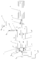
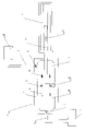
- FIG. 12 is a conceptual diagram of a high-pressure gas station assumed from Japanese Patent No. 6160876.
- the high-pressure gas station includes a transport tank 20 for movement, a connection valve 21 attached to and detached from the tank 20, a transfer line 22 having a connection valve 21 at the end, and a 3-way valve 23 provided in the middle of the transfer line 22.
- a bypass line 24 switched by the 3-way valve 23 and a storage gas high pressure line 26 via a transfer compressor 36 are provided.
- the storage gas high pressure line 26 is connected to the storage tank 27, the pressure line 29 is connected to the outlet of the storage tank 27 via the pressurizing compressor 37, the refueling tank 30 is connected to the pressurizing line 29, and further.
- a refueling valve 32 is provided at the outlet of the refueling tank 30 via a high pressure refueling line 31. This makes it possible to refuel the gas vehicle 33.
- a management building 34 and a site 35 are provided.
- the concept of the high pressure gas station in FIG. 12 is as follows. (1) It is assumed that the initial pressure of the transport tank 20 is 60 MPa. It is assumed that the pressure of the storage tank 27 is 60 MPa. It is assumed that the pressure of the refueling tank 30 is 80 MPa. It is assumed that the compression ratio of the transfer compressor 36 is 20: 1. It is assumed that the compression ratio of the pressurizing compressor 37 is 20: 1. (2) In the high-pressure gas station of FIG. 12, there are two methods for transferring high-pressure gas of 60 MPa from the transport tank 20 to the storage tank 27. The 60 MPa high pressure gas filled in the transport tank 20 is transported from the gas supply base.
- A One is a transport tank 20, a connection valve 21, a transfer line 22, a 3-way valve 23, a bypass line 24, and a line directly sent from the storage gas high pressure line 26 to the storage tank 27.
- B Another is a transport tank 20, a connection valve 21, a transfer line 22, a 3-way valve 23, a transfer compressor 36, and a line from the storage gas high pressure line 26 to the storage tank 27.
- the transfer compressor 36 pressurizes and transfers the high-pressure gas transported in the transport tank 20 to the storage tank 27.
- the pressure of the storage tank 27 is 60 MPa.
- the transfer line 22, the 3-way valve 23, the bypass line 24, the transfer compressor 36, the storage gas high pressure line 26, and the storage tank 27 are installed underground.
- the 60 MPa high-pressure gas stored in the storage tank 27 is pressurized and transferred to the 80 MPa refueling tank 30 by the pressurizing compressor 37 through the pressurizing line 29.
- the pressurizing compressor 37, the pressurizing line 29, and the refueling tank 30 are installed underground.
- the 80 MPa high-pressure gas stored in the refueling tank 30 is refueled to the gas vehicle 33 by the refueling valve 32 through the refueling high-pressure line 31.
- the transportation tank 20 is a transportation gas tank from the gas supply base to the gas station.
- the transport tank 20 is made of a honeycomb structure high pressure tank assumed from Japanese Patent No. 6160876.
- the initial pressure of the transport tank 20 is assumed to be 60 MPa.
- connection valve 21 is an on-off valve to the transfer line 22.
- the transfer line 22 is connected to the 3-way valve 23.
- the 3-way valve 23 is a switching valve for the bypass line 24 and the transfer compressor 36.
- the bypass line 24 and the transfer compressor 36 are connected to the storage gas high pressure line 26.
- the bypass line 24 coming out of the 3-way valve 23 is connected in the middle of the storage gas high pressure line 26.
- the gas in the transport tank 20 flows directly to the storage gas high pressure line 26.
- the transfer compressor 36 is connected to the storage gas high pressure line 26.
- the storage gas high pressure line 26 is connected to the storage tank 27.
- the transfer compressor 36 transfers the high-pressure gas of the transport tank 20 to the storage tank 27.
- the storage tank 27 is a gas tank that stores high-pressure gas transported from the gas supply base by the transportation tank 20. Like the transportation tank 20, the storage tank 27 is made of a honeycomb structure high pressure tank assumed from Japanese Patent No. 6160876.
- the pressurizing compressor 37 is connected to the storage tank 27 by a high pressure pipeline.
- the pressurizing compressor 37 pressurizes the high-pressure gas in the storage tank 27 to 80 MPa.
- the high pressure gas pressurized to 80 MPa is sent to the refueling tank 30 through the pressurizing line 29.
- the pressurizing line 29 is a high pressure pipeline that can withstand a high pressure of 80 MPa or more.
- the refueling tank 30 is an ultra-high pressure gas tank assumed to be 80 MPa.
- the refueling tank 30 stores high-pressure gas for refueling the gas vehicle 33.
- the refueling tank 30 is made of a honeycomb structure high pressure tank assumed from Japanese Patent No. 6160876.
- the refueling high pressure line 31 is connected to the refueling tank 30.
- the refueling high-pressure line 31 is an ultra-high pressure gas pipeline that transfers the high-pressure gas stored in the refueling tank 30 to the refueling valve 32.
- the refueling valve 32 is a pressure adjusting valve that refuels the gas vehicle 33 with high-pressure gas.
- the gas vehicle 33 is a vehicle that has an in-vehicle gas tank such as natural gas or hydrogen gas.
- the gas tank of the gas vehicle 33 is assumed to be 60 MPa.
- the management building 34 and the site 35 are the management building and the site of the gas station.
- the high pressure gas station system shown in FIG. 12 seems to work well. However, it does not fully realize the function with the conventional technique. The reason is as follows. (1) In order to refuel the in-vehicle gas tank of the gas vehicle 33 with high pressure gas of 60 MPa, it is desirable to maintain the internal pressure of the refueling tank 30 at 80 MPa. (2) The ultra-high pressure gas in the refueling tank 30 is supplied from the storage tank 27 by the pressurizing compressor 37. It is assumed that the pressurizing compressor 37 is a piston type compressor having a compression ratio of 20: 1 in the prior art.
- the pressurizing compressor 37 can easily produce 80 MPa ultra-high pressure gas from 60 MPa high pressure gas, so that 80 MPa gas is supplied to the refueling tank 30. It's easy to do.
- a high pressure gas of 60 MPa and 1000 cc becomes an ultra high pressure gas of 80 MPa and 750 cc.
- the compression ratio is 1.33: 1.0.
- the compression ratio of the pressurizing compressor 37 is larger than this value.
- the high pressure gas is continuously supplied from the storage tank 27 to the refueling tank 30, the internal pressure of the storage tank 27 gradually decreases.
- the pressurizing compressor 37 cannot supply the ultra-high pressure gas of 80 MPa to the refueling tank 30. That is, the high-pressure gas of 4.0 MPa or less remaining in the storage tank 27 becomes completely dead stock. 4.0 MPa is about 40 atmospheres.
- a multi-stage piston with a compression ratio of 40: 1 is used for the compressor, it can be used until the pressure of the storage tank 27 is reduced to 2.0 MPa.
- a multi-stage piston is a combination of a first piston and a second piston. When the pressure of the storage tank 27 is 4.0 MPa or more, the second piston of the multi-stage piston becomes a useless obstacle.
- the relationship between the transport tank 20 and the storage tank 27 is also the same. To simplify the calculation, it is assumed that the internal pressure of the transport tank 20 is 60 MPa and the internal pressure of the storage tank 27 is zero. Then, it is assumed that the volume of the transportation tank 20 is 3000 liters, and the volume of the storage tank 27 is also 3000 liters. Simply put, it is assumed that 3000 liters, 60 MPa high pressure gas is transferred from a transport tank to an empty underground tank. If this transfer is done in the prior art, it would be: (1) The transportation tank 20 is transported from the gas supply base to the gas station.
- the transportation tank 20 is connected to the transfer line 22, the 3-way valve 23, the bypass line 24, the transfer compressor 36, the storage gas high pressure line 26, and the storage tank 27 by the connection valve 21.
- the connection valve 21 When the connection valve 21 is opened, the high pressure gas of 60 MPa moves through the transfer line 22 to the 3-way valve 23.
- the 3-way valve 23 When the 3-way valve 23 is opened to the bypass line 24, the high pressure gas of 60 MPa flows into the storage tank 27 through the bypass line 24 and the storage gas high pressure line 26.
- the high-pressure gas of the transportation tank 20 stops flowing when the internal pressure of the storage tank 27 reaches 30 MPa.
- the 30 MPa high-pressure gas remaining in the transport tank 20 is left in the transport tank 20 as dead stock.
- the pressure inside the storage tank 27 stays at 30MPa and does not reach 60MPa. That is, it is not possible to transport the high pressure gas in the transport tank to the underground tank simply by opening the bypass valve.
- the prior art piston compressor challenges this challenge. Even if the inlet pressure fluctuates greatly, the piston type compressor is effective.
- the transfer compressor 36 is a conventional piston type compressor having a compression ratio of 20: 1.
- the transfer compressor 36 can easily produce 60 MPa high-pressure gas from 30 MPa high-pressure gas, when the internal pressure of the transport tank 20 is 30 MPa, 30 MPa high-pressure gas is transferred to the storage tank 27. It's easy.
- the high pressure gas of 30MPa and 1000cc becomes the high pressure gas of 60MPa and 500cc.
- the compression ratio is 2: 1.
- the compression ratio of the transfer compressor 36 is larger than this value.
- the invention described here is a newly invented compressor for transferring high-pressure gas, and the compressor realizes the function of a high-pressure gas station.
- the newly invented compressor is a compressor that realizes the function of a multi-stage piston with a single piston.
- the piston type compressor of the prior art is insufficient to realize the high pressure gas station explained by the "problem to be solved by the invention".
- a new type of compressor is needed.
- the prior art piston scheme is not completely useless. It is quite effective where the fluctuation range of the inlet pressure is large and the outlet pressure becomes high pressure. If the compressor of the present invention can obtain the function of a multi-stage piston without a second piston, the above problem can be solved. That is, if a compressor having a multi-stage piston type function can be invented with one piston, the high-pressure gas station shown in FIG. 12 can be realized.
- Two pressurizing chambers are required to obtain the function of a multi-stage compressor with one piston. It looks impossible, but it's not impossible.
- a two-stroke engine two-stroke period
- has a pressurizing chamber behind the engine piston In the case of pistons and cylinders, they are called double-acting cylinders.
- the present invention uses a linear actuator (linear actuator) or a linear motor to move the piston.
- linear actuators are inferior to rapid pressurization.
- refueling by the high-pressure gas station is refueled by the pressure difference between the high-pressure gas of the gas station and the in-vehicle tank of the gas vehicle, so that the transfer compressor does not need to rapidly pressurize the high-pressure gas. Therefore, the capacity required for the compressor in FIG. 1 is not immediate effect but continuous power.
- Linear actuators and linear motors are excellent in the convenience of drive devices. The simplicity of the drive makes it easy to enhance the structural strength.
- the compressor according to the present invention has a piston that divides the inside of the cylinder into a compression chamber and an intake chamber, and the piston is provided with a check valve that can be opened only in the direction from the intake chamber to the compression chamber.
- a check valve that can be opened only in the outlet direction is provided at the outlet of the chamber, and a check valve that can be opened only into the chamber is provided at the inlet of the intake chamber, and the internal volumes of both chambers are variable for the piston. It is characterized by connecting an actuator.
- the compressor is characterized in that the output tank can be continuously filled with high-pressure gas even if the gas pressure of the supply tank supplied to the intake chamber is reduced.
- the high-pressure gas station according to the present invention is a high-pressure gas station equipped with a compressor having the above configuration. Further, in this case, even if the gas pressure of the transportation tank is reduced, the high-pressure gas can be continuously transferred to the storage tank. Further, even if the gas pressure of the storage tank is reduced, the high-pressure gas can be continuously transferred to the refueling tank for the gas vehicle.
- a compressor is placed in the path connecting the pair of high-pressure tanks, and this compressor has a piston that divides the inside of the cylinder into a compression chamber and an intake chamber, and the piston has a check valve that can be opened only in the direction from the intake chamber to the compression chamber.
- the outlet of the compression chamber is provided with a check valve that can be opened only in the outlet direction
- the inlet of the intake chamber is provided with a check valve that can be opened only into the chamber
- the piston is provided with the internal volumes of both chambers. It is characterized in that one high-pressure tank is connected to the inlet of the compressor and the other high-pressure tank is connected to the outlet.
- FIG. 1 It is sectional drawing which shows the conceptual structure of a compressor.
- the process diagram of the intake air-1 of the compressor is shown.
- the process diagram of the intake-2 of the compressor is shown.
- the process diagram of transfer-1 of the compressor is shown.
- the process diagram of transfer-2 of the compressor is shown.
- the process diagram of compression-1 of the compressor is shown.
- the process diagram of compression-2 of the compressor is shown.
- the process diagram of transfer-3 of the compressor is shown.
- the process diagram of transfer-4 of the compressor is shown.
- the process diagram of compression-3 of the compressor is shown.
- the conceptual diagram of the high pressure gas station which concerns on this invention is shown.
- the conceptual diagram of the conventional high pressure gas station is shown.
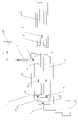
- FIG. 1 shows a conceptual diagram of the multi-function compressor 1.
- the multifunction compressor 1 includes a cylinder 2, a piston 3, a piston rod 4, a linear actuator 5, an inlet pipe 6, an outlet pipe 7, an inlet valve 8, an outlet valve 9, an intermediate valve 10, an intake chamber 11, a compression chamber 12, and a supply tank 13. , And an output tank 14.
- Cylinder 2 is a cylinder of a single piston type compressor.
- the cylinder 2 can be filled with high-pressure gas.
- the piston 3 is a piston of a single piston type compressor.
- the piston 3 can pressurize a high pressure gas.
- the piston rod 4 is a piston rod that drives the piston 3.
- the piston rod 4 performs only linear motion.
- the linear actuator 5 is an operating device that operates the piston rod 4 only in the linear direction.
- the linear actuator 5 is a device driven by an electrically driven ball screw or a linear motor.
- the supply tank 13 is a high-pressure gas tank for transportation. It is assumed that the initial pressure of the supply tank 13 is 60 MPa.
- the output tank 14 is a high-pressure gas tank for refueling a gas vehicle. It is assumed that the internal pressure of the output tank 14 is maintained at 80 MPa. Gas vehicles are not shown in FIG. It is assumed that the compression ratio of the multifunction compressor 1 is 20: 1.
- the inlet pipe 6 is a high-pressure pipe connecting the supply tank 13 and the multifunction compressor 1.
- the outlet pipe 7 is a high-pressure pipeline connecting the multifunction compressor 1 and the output tank 14.
- the inlet valve 8 is a check valve.
- the inlet valve 8 is placed at the inlet of the multifunction compressor 1. Since the inlet valve 8 is a one-way check valve, the high-pressure gas in the supply tank 13 flows in one direction from the supply tank 13 to the multifunction compressor 1.
- the outlet valve 14 is a check valve.
- the outlet valve 14 is placed at the outlet of the multifunction compressor 1. Since the outlet valve 9 is a one-way check valve, the compressed gas of the multi-function compressor 1 flows in one direction from the multi-function compressor 1 to the output tank 14.
- the cylinder 2 of the multifunction compressor 1 is divided into two chambers by the piston 3. One is the intake chamber 11 and the other is the compression chamber 12. The intake chamber 11 and the compression chamber 12 are connected through an intermediate valve 10.
- the intermediate valve 10 is a one-way check valve.
- the intermediate valve 10 is placed on the bearing wall of the piston 3. It is desirable that there are a plurality of intermediate valves 10. Since the intermediate valve 10 is a one-way check valve, the compressed gas in the intake chamber 11 flows from the intake chamber 11 to the compression chamber 12 in only one direction.
- the principle of the present invention is the same as that of a two-stroke engine. That is, intake and compression are performed simultaneously in one cycle of the piston. However, at the same time, when explaining the process of inspiration and the process of compression, it becomes too complicated. This paragraph describes the inspiratory process.
- the inspiratory process is as follows.
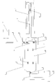
- FIG. 2 shows the process chart of intake -1.
- the process chart of intake-1 is a multi-function compressor 1, cylinder 2, piston 3, piston rod 4, linear actuator 5, inlet pipe 6, outlet pipe 7, inlet valve 8, outlet valve 9, intermediate valve 10, intake chamber 11, It is composed of a compression chamber 12, a supply tank 13, an output tank 14, an intake gas 15, and a piston operation 16.
- the intake gas 15 is a gas supplied from the supply tank 13.
- the initial pressure of the supply tank 13 is assumed to be 60 MPa.
- the piston operation 16 is a movement of the piston 3 and the piston rod 4.
- the direction of the piston operation 16 is indicated by the direction of the arrow.
- the process of intake-1 shown in FIG. 2 is as follows. (1) The piston rod 4 moves in the direction of the arrow of the piston operation 16. (A) The volume of the intake chamber 11 becomes large. (B) The volume of the compression chamber 12 becomes smaller. (2) When the volume of the intake chamber 11 becomes large, the following events occur in the inlet valve 8, the intake chamber 11, and the supply tank 13. (A) The internal pressure of the intake chamber 11 becomes smaller than the internal pressure of the supply tank 13. (B) The inlet valve 8 is opened. (C) The intake chamber 11 is filled with gas flowing from the supply tank 13 through the inlet pipe 6 into the intake chamber 11. (3) When the volume of the compression chamber 12 becomes small, the following events occur in the intermediate valve 10, the intake chamber 11, and the compression chamber 12. (A) The internal pressure of the compression chamber 12 becomes larger than the internal pressure of the intake chamber 11. (B) The intermediate valve 10 is closed. (C) The gas in the compression chamber 12 is compressed by the piston 3. (D) The internal pressure of the compression chamber 12 becomes higher.
- FIG. 3 shows the process chart of intake-2.
- the process chart of intake-2 is a multi-function compressor 1, cylinder 2, piston 3, piston rod 4, linear actuator 5, inlet pipe 6, outlet pipe 7, inlet valve 8, outlet valve 9, intermediate valve 10, intake chamber 11, It is composed of a compression chamber 12, a supply tank 13, an output tank 14, an intake gas 15, and a piston operation 16.
- the intake gas 15 is a gas supplied from the supply tank 13. As the amount of the intake gas 15 increases, the internal pressure of the supply tank 13 gradually decreases.
- the piston operation 16 is a movement of the piston 3 and the piston rod 4. The direction of the piston operation 16 is indicated by the direction of the arrow, and the piston operation 16 in FIG. 3 is stopped at the left end of the linear actuator 5.
- the process of intake-2 shown in FIG. 3 is as follows. (1) The piston rod 4 moves in the direction of the arrow of the piston operation 16 and stops at the left end of the linear actuator 5. (A) The volume of the compression chamber 12 is the smallest. (B) The volume of the intake chamber 11 is the largest. (2) When the volume of the compression chamber 12 is the smallest, the following events occur in the intermediate valve 10, the intake chamber 11, and the compression chamber 12. (A) The pressure inside the compression chamber 12 is higher than the pressure inside the intake chamber 11. (B) The intermediate valve 10 is kept closed. (C) The gas in the compression chamber 12 is maximally compressed by the piston 3. (D) The internal pressure of the compression chamber 12 becomes the maximum.
- FIG. 4 shows the process chart of transfer-1.
- the process chart of transfer-1 is a multi-function compressor 1, cylinder 2, piston 3, piston rod 4, linear actuator 5, inlet pipe 6, outlet pipe 7, inlet valve 8, outlet valve 9, intermediate valve 10, intake chamber 11, It is composed of a compression chamber 12, a supply tank 13, an output tank 14, an intake gas 15, a transfer gas 17, and a piston operation 16.
- the intake gas 15 is the gas left in the intake chamber 11 in the pre-process shown in FIG.
- the transfer gas 17 is a gas transferred from the intake chamber 11 to the compression chamber 12 by the action of the piston 3 and the intermediate valve 10.
- the process of transfer-1 shown in FIG. 4 is as follows. (1) The piston rod 4 moves in the direction of the arrow of the piston operation 16. (A) The volume of the intake chamber 11 becomes smaller. (B) The volume of the compression chamber 12 becomes large. (2) When the volume of the intake chamber 11 becomes small, the following events occur in the inlet valve 8, the intake chamber 12, and the supply tank 13. (A) The gas filling the intake chamber 11 is compressed by the piston 3. (B) The internal pressure of the intake chamber 11 becomes larger than the internal pressure of the supply tank 13. (C) The inlet valve 8 is closed. (3) When the volume of the compression chamber 12 becomes large and the volume of the intake chamber 11 becomes small, the following events occur in the intermediate valve 10, the intake chamber 11, and the compression chamber 12.
- FIG. 5 shows the process chart of Transfer-2.
- the process chart of Transfer-2 is a multi-function compressor 1, cylinder 2, piston 3, piston rod 4, linear actuator 5, inlet pipe 6, outlet pipe 7, inlet valve 8, outlet valve 9, intermediate valve 10, intake chamber 11, It is composed of a compression chamber 12, a supply tank 13, an output tank 14, a transfer gas 17, and a piston operation 16.
- the transfer gas 17 is a gas transferred from the intake chamber 11 to the compression chamber 12.
- the process of transfer-2 shown in FIG. 5 is as follows. (1) The piston rod 4 moves in the direction of the arrow of the piston operation 16 and stops at the right end of the linear actuator 5. (A) The volume of the compression chamber 12 is the largest. (B) The volume of the intake chamber 11 is the smallest. (2) When the volume of the compression chamber 12 becomes the largest, the following events occur in the intermediate valve 10, the intake chamber 11, and the compression chamber 12. (A) The intermediate valve 10 is open until the piston 3 and the piston rod 4 stop at the right end of the linear actuator 5. (B) The transfer gas 17 is transferred from the intake chamber 11 to the compression chamber 12 until the piston 3 and the piston rod 4 stop at the right end of the linear actuator 5.
- the principle of this invention is the same as that of a two-stroke engine. That is, intake and compression are performed simultaneously in one cycle of the piston.
- an object of the present invention is to obtain the function of a multi-stage piston with only one piston.
- This paragraph describes the process of compression.
- the case (No. 1) is a case where the internal pressure of the compression chamber becomes larger than the internal pressure of the output tank.
- the case (No. 2) is a case where the internal pressure of the compression chamber does not increase as much as the internal pressure of the output tank.
- FIG. 6 shows a process chart of compression-1.
- the process chart of compression-1 is a multi-function compressor 1, cylinder 2, piston 3, piston rod 4, linear actuator 5, inlet pipe 6, outlet pipe 7, inlet valve 8, outlet valve 9, intermediate valve 10, intake chamber 11, It is composed of a compression valve 12, a supply tank 13, an output tank 14, a compressed gas 18, a piston operation 16, and an intake gas 15.
- the compressed gas 18 is a gas that has been transferred from the intake chamber 11 to the compression chamber 12 and remains in the compression chamber 12. Since the internal pressure of the compression chamber 12 is higher than the internal pressure of the intake chamber 11, the intermediate valve 10 is closed. The compressed gas 18 is gradually compressed by the piston 3.
- the intake gas 15 is a gas extracted from the supply tank 13. As the amount of the intake gas 15 increases, the internal pressure of the supply tank 13 gradually decreases.
- the process of compression-1 shown in FIG. 6 is as follows. (1) The piston rod 4 moves in the direction of the arrow of the piston operation 16. (A) The volume of the compression chamber 12 becomes smaller. (B) The volume of the intake chamber 11 becomes large. (2) When the volume of the compression chamber 12 becomes small and the volume of the intake chamber 11 becomes large, the following events occur in the intermediate valve 10, the intake chamber 11, the compression chamber 12, the compressed gas 18, and the output tank 14. (A) The internal pressure of the compression chamber 12 becomes larger than the internal pressure of the intake chamber 11. (B) The intermediate valve 10 is closed. (C) The gas in the compression chamber 12 is compressed by the piston 3. (D) The internal pressure of the compression chamber 12 increases steadily.
- the multifunction compressor can transfer the intake gas from the supply tank to the output tank by repeating intake-1, intake-2, transfer-1, transfer-2 and compression-1. ..
- the newly invented multi-function compressor can transfer the intake gas from the supply tank to the output tank without any obstacles until the internal pressure of the compression chamber becomes smaller than the internal pressure of the output tank. ..
- FIG. 7 shows the process chart of compression-2.
- the process chart of compression-2 is a multi-function compressor 1, cylinder 2, piston 3, piston rod 4, linear actuator 5, inlet pipe 6, outlet pipe 7, inlet valve 8, outlet valve 9, intermediate valve 10, intake chamber 11, It is composed of a compression valve 12, a supply tank 13, an output tank 14, a compressed gas 18, a piston operation 16, and an intake gas 15.
- the compressed gas 18 is a gas that has been transferred from the intake chamber 11 to the compression chamber 12 and remains in the compression chamber 12. Since the internal pressure of the compression chamber 12 is higher than the internal pressure of the intake chamber 11, the intermediate valve 10 is closed. When the piston operation 16 stops at the left end of the linear actuator 5, the compressed gas 18 is maximally compressed by the piston 3.
- the case (No. 2) is more complicated than the case (No. 1).
- the compression ratio of the multifunction compressor is 20: 1
- the internal pressure of the output tank is 80 MPa
- the internal pressure of the supply tank is 4.0 MPa.
- the process of compression-2 shown in FIG. 7 is as follows. (1) The piston rod 4 moves in the direction of the arrow of the piston operation 16 and stops at the left end of the linear actuator 5.
- the volume of the compression chamber 12 is the smallest.
- (B) The volume of the intake chamber 11 is the largest.
- the compressed gas 18 remains in the compression chamber 12, and the inside of the intake chamber 11 is filled with the intake gas 15.
- the compressed gas 18 is almost 80 MPa, but the pressure is not high enough to be discharged to the output tank 14.
- the intake gas 15 is almost 4.0 MPa.
- FIG. 8 shows the process chart of Transfer-3.
- the process chart of Transfer-3 is a multi-function compressor 1, cylinder 2, piston 3, piston rod 4, linear actuator 5, inlet pipe 6, outlet pipe 7, inlet valve 8, outlet valve 9, intermediate valve 10, intake chamber 11, It is composed of a compression valve 12, a supply tank 13, an output tank 14, a compressed gas 18, a piston operation 16, and an intake gas 15.
- the compressed gas 18 is the gas remaining inside the compression chamber 12.
- the initial pressure of the compressed gas 18 is 80 MPa, but it decreases to about 4.0 MPa as the compression chamber 12 expands.
- the intake gas 15 is a gas left inside the intake chamber 11.
- the initial pressure of the intake gas 15 is 4.0 MPa, but it increases to about 80 MPa as the intake chamber 11 shrinks.
- the piston operation 16 is a movement of the piston 3 and the piston rod 4. As the piston movement 16 moves to the right, the compression chamber 12 becomes larger and the intake chamber 11 becomes smaller.
- FIG. 8 shows the moment when the pressure of the intake gas 15 becomes higher than the pressure of the compressed gas 18.
- the piston rod 4 is moving in the direction of the arrow of the piston operation 16.
- A The volume of the compression chamber 12 becomes large.
- B The volume of the intake chamber 11 becomes smaller.
- B When the volume of the compression chamber 12 becomes larger than the volume of the intake chamber 11, the following events occur in the intermediate valve 10, the intake chamber 11, and the compression chamber 12.
- A The internal pressure of the compression chamber 12 becomes smaller than the internal pressure of the intake chamber 11.
- B) The intermediate valve 10 is opened.
- C The intake gas 15 of the intake chamber 11 flows into the compression chamber 12 and mixes with the compressed gas 18.
- FIG. 9 shows the process chart of Transfer-4.
- the process chart of Transfer-4 is a multi-function compressor 1, cylinder 2, piston 3, piston rod 4, linear actuator 5, inlet pipe 6, outlet pipe 7, inlet valve 8, outlet valve 9, intermediate valve 10, intake chamber 11, It is composed of a compression valve 12, a supply tank 13, an output tank 14, a mixed gas 19, an intake gas 15, and a piston operation 16.
- FIG. 9 shows the moment when the piston rod 4 moves in the direction of the arrow of the piston operation 16 and stops at the right end of the linear actuator 5.
- the mixed gas 19 is a gas in which the gas left inside the compression chamber 12 and the intake gas 15 from the intake chamber 11 are mixed.
- the process of Transfer-4 shown in FIG. 9 is as follows. (1) The piston rod 4 moves in the direction of the arrow of the piston operation 16 and stops at the right end of the linear actuator 5.
- A The volume of the compression chamber 12 is the largest.
- B The volume of the intake chamber 11 is the smallest.
- B The intake gas 15 of the intake chamber 11 flows into the compression chamber 12 and becomes a mixed gas 19.
- C When the pressure of the intake gas 15 and the pressure of the mixed gas 19 become equal, the intermediate valve 10 is closed. (3) It is not easy to calculate the pressure of the mixed gas 19 accurately. However, a rough calculation is possible.
- FIG. 10 shows the process chart of compression-3.
- the process chart of compression-3 is a multi-function compressor 1, cylinder 2, piston 3, piston rod 4, linear actuator 5, inlet pipe 6, outlet pipe 7, inlet valve 8, outlet valve 9, intermediate valve 10, intake chamber 11, It is composed of a compression valve 12, a supply tank 13, an output tank 14, a compressed gas 18, a piston operation 16, and an intake gas 15.
- FIG. 10 shows the moment when the piston rod 4 moves in the direction of the arrow of the piston operation 16 and stops at the left end of the linear actuator 5.
- the compressed gas 18 is a gas obtained by compressing the mixed gas 19 shown in FIG. 9 with the piston 3.
- the intake gas 15 is a gas newly supplied from the supply tank 13.
- the process of compression-3 is as follows. (1) The piston rod 4 moves in the direction of the arrow of the piston operation 16 and stops at the left end of the linear actuator 5.
- the volume of the compression chamber 12 is the smallest.
- the volume of the intake chamber 11 is the largest.
- the initial compressed gas 18 is estimated to be 8.0 MPa.
- the compressed gas 18 in the compression chamber 12 is maximally compressed by the piston 3.
- the compression ratio of the multifunction compressor 1 is assumed to be 20: 1. Therefore, the compressed gas 18 is compressed to 160 MPa.
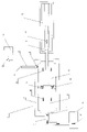
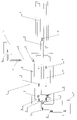
- FIG. 11 shows a conceptual diagram of the high pressure gas station according to the embodiment.
- the high-pressure gas station includes a transportation tank 20, a connection valve 21, a transfer line 22, a 3-way valve 23, a bypass line 24, a transfer compressor 25, a storage gas high-pressure line 26, a storage tank 27, a pressurizing compressor 28, and a pressurizing line. 29, a refueling tank 30, a refueling high-pressure line 31, a refueling valve 32, a gas vehicle 33, a management building 34, and a site 35.
- the transfer compressor 25 and the pressurizing compressor 28 are the same as the multifunction compressor 1 shown in FIG.
- the concept of the high pressure gas station in FIG. 11 is as follows. (1) It is assumed that the initial internal pressure of the transportation tank 20 is 60 MPa. It is assumed that the internal pressure of the storage tank 27 is 60 MPa. It is assumed that the internal pressure of the refueling tank 30 is 80 MPa. It is assumed that the compression ratio of the transfer compressor 25 is 20: 1. It is assumed that the compression ratio of the pressurizing compressor 28 is 20: 1. (2) In the high-pressure gas station shown in FIG. 11, there are two lines for transferring 60 MPa high-pressure gas from the transport tank 20 to the storage tank 27. It is assumed that the high pressure gas of 60 MPa is carried from the gas supply base.
- A One is a transport tank 20, a connection valve 21, a transfer line 22, a 3-way valve 23, a bypass line 24, and a line from the storage gas high pressure line 26 to the storage tank 27.
- B Another is a transport tank 20, a connection valve 21, a transfer line 22, a 3-way valve 23, a transfer compressor 25, and a line from the storage gas high pressure line 26 to the storage tank 27.
- the transfer compressor 25 pressurizes and transfers the gas in the transport tank 20 to the storage tank 27.
- the pressure of the storage tank 27 is 60 MPa.
- the transfer line 22, the 3-way valve 23, the bypass line 24, the transfer compressor 25, the storage gas high pressure line 26, and the storage tank 27 are installed underground.
- the 60 MPa gas stored in the storage tank 27 is pressurized and transferred to the 80 MPa refueling tank 30 through the pressurizing line 29 by the pressurizing compressor 28.
- the pressurizing compressor 28, the pressurizing line 29, and the refueling tank 30 are installed underground.
- the 80 MPa high-pressure gas stored in the refueling tank 30 is refueled from the refueling valve 32 to the gas vehicle 33 through the refueling high-pressure line 31.
- the transportation tank 20 is a transportation gas tank from the gas supply base to the high pressure gas station.
- the transport tank 20 is made of a honeycomb structure high pressure gas tank assumed from Japanese Patent No. 6160876.
- the connection valve 21 is an on-off valve to the transfer line 22.
- the transfer line 22 is connected to the 3-way valve 23.
- the 3-way valve 23 is a switching valve for the bypass line 24 and the transfer compressor 25.
- the bypass line 24 and the transfer compressor 25 are connected to the storage gas high pressure line 26.
- the bypass line 24 from the 3-way valve 23 is connected in the middle of the storage gas high pressure line 26.
- the transfer compressor 25 is connected to the storage gas high pressure line 26.
- the storage gas high pressure line 26 is connected to the storage tank 27.
- the transfer compressor 25 transfers the gas in the transport tank 20 to the storage tank 27.
- the storage tank 27 is a high-pressure gas tank for storing the high-pressure gas transported from the gas supply base by the transportation tank 20.
- the storage tank 27 is made of a honeycomb structure high pressure gas tank assumed from Japanese Patent No. 6160876.
- the pressurizing compressor 28 is connected to the storage tank 27 by a pipeline.
- the pressurizing compressor 28 pressurizes the gas in the storage tank 27 to 80 MPa.
- the gas pressurized to 80 MPa is sent to the refueling tank 30 through the pressurizing line 29.
- the pressurizing line 29 is a pipeline that can withstand a high pressure of 80 MPa or more.
- the refueling tank 30 is an ultra-high pressure gas tank assuming an operating pressure of 80 MPa.
- the refueling tank 30 stores the gas to be refueled in the gas vehicle 33.
- the refueling tank 30 is made of a honeycomb structure high pressure gas tank assumed from Japanese Patent No. 6160876.
- the refueling high pressure line 31 is connected to the refueling tank 30.
- the refueling high-pressure line 31 is an ultra-high pressure gas pipeline that distributes the high-pressure gas stored in the refueling tank 30 to the refueling valve 32.
- the refueling valve 32 is a valve that refuels the gas vehicle 33 with high-pressure gas.
- the gas vehicle 33 is a vehicle that stores natural gas and hydrogen gas in an in-vehicle tank.
- the in-vehicle gas tank of the gas vehicle 33 is assumed to be 60 MPa.
- the management building 34 and the site 35 are the boundaries between the management building of the gas station and the gas station.
- the system of the high-pressure gas station shown in FIG. 11 is a specific example of realizing the function of refueling a gas vehicle with high-pressure gas.
- the compressor according to the present invention has an ability to keep the discharge pressure of the compressed gas constant even under the condition that the intake pressure to the compressor supplied from the storage tank gradually decreases.
- the process of continuing to refuel a gas vehicle with high-pressure gas is as follows. (1) In order to refuel the in-vehicle gas tank of the gas vehicle 33 with high pressure gas of 60 MPa, it is desirable that the internal pressure of the refueling tank 30 is maintained at 80 MPa. (2) The gas in the refueling tank 30 is supplied from the storage tank 27 by the pressurizing compressor 28.
- the pressurizing compressor 28 is the multifunction compressor 1 of FIG.
- the multifunction compressor 1 according to the present invention is a piston type compressor.
- the compression ratio is assumed to be 20: 1.
- the pressurizing compressor 28 can easily produce 80 MPa ultra-high pressure gas from 60 MPa high pressure gas, so that 80 MPa gas is supplied to the refueling tank 30. It's easy.
- the high-pressure gas of 1000 cc and 60 MPa becomes the ultra-high pressure gas of 750 cc and 80 MPa.
- the compression ratio in that case is only "1.33: 1".
- (5) When the gas from the storage tank 27 is continuously supplied to the refueling tank 30, the internal pressure of the storage tank 27 gradually decreases.
- the transfer compressor 25 and the pressurizing compressor 28 are the multifunction compressor 1 shown in FIG.
- the multifunction compressor 1 can double the exhaust pressure by inhaling twice. There is no limit to the number of inspirations. Therefore, even if the pressure of the storage tank 27 becomes 4.0 MPa or less, the pressurizing compressor 28 can continue to supply the gas of 80 MPa to the refueling tank 30.
- the multifunction compressor 1 can compress the pressure of 2.0 MPa to 80 MPa by moving the piston 3 twice. Further, the multifunction compressor 1 can pressurize the pressure of 1.3 MPa to 80 MPa by moving the piston 3 three times. Since the multifunction compressor 1 is not a combination of two pistons, there is no obstacle to the gas refueling system.
- the internal pressure of the transport tank 20 is 60 MPa. It is assumed that the internal pressure of the storage tank 27 is zero. Then, it is assumed that the volume of the transport tank 20 is 3000 liters. The volume of the storage tank 27 is also set to 3000 liters. Simply put, consider the case of transferring 60 MPa, 3000 liters of high pressure gas from a transport tank to an empty underground tank. When this work is done with the newly invented compressor, it is: (1) The transportation tank 20 is transported from the gas supply base to the gas station.
- the transportation tank 20 is connected to the transfer line 22, the 3-way valve 23, the bypass line 24, the transfer compressor 25, the storage gas high pressure line 26, and the storage tank 27 by the connection valve 21.
- the connection valve 21 When the connection valve 21 is opened, the high-pressure gas of 60 MPa moves to the 3-way valve 23 through the transfer line 22.
- the 3-way valve 23 When the 3-way valve 23 is opened toward the bypass line 24, the high pressure gas of 60 MPa flows into the storage tank 27 through the bypass line 24 and the storage gas high pressure line 26.
- the high-pressure gas of the transportation tank 20 stops flowing when the internal pressure of the storage tank 27 reaches 30 MPa.
- the high-pressure gas of 30 MPa is left in the transport tank 20 as dead stock.
- the internal pressure of the storage tank 27 stops at 30 MPa and does not reach 60 MPa. In other words, it is not possible to transfer all the high-pressure gas in the transport tank to the underground tank simply by opening the bypass valve.
- the transfer compressor 25 is the multifunction compressor 1 in FIG. It is also assumed that the compression ratio is 20: 1.
- the transfer compressor 25 can easily produce a high pressure gas of 60 MPa from the high pressure gas of 30 MPa, so that the gas of 30 MPa is transferred to the storage tank 27. It's easy to do.
- the high pressure gas of 1000cc and 30MPa becomes the high pressure gas of 500cc and 60MPa.
- the compression ratio is 2: 1.
- the transfer compressor 25 can transport the gas of 3.0 MPa or less to the storage tank 27.
- the multifunction compressor 1 in FIG. 1 can compress a gas of 1.5 MPa to 60 MPa by moving the piston 3 twice. Further, it is possible to compress the gas of 1.0 MPa to 60 MPa by moving the piston 3 three times.
- the compressor of the present invention is effective even if the inlet pressure of the compressor changes significantly.
- the shape and purpose of the compressor of the present invention may be changed in various ways.
- the spirit of the present invention is a compressor that realizes the function of a multi-stage piston system with only one piston and cylinder.
- the compressor of the present invention can be applied when the fluctuation range of the inlet pressure is large and a high-pressure compressed gas is required for the outlet pressure.
- Multi-function compressor compressor
- 2 Cylinder
- 3 Piston
- 4 Piston rod
- 5 Linear actuator
- 6 Inlet pipe (check valve), 7 ?? Outlet pipe (check) Valve
- 8 ... inlet valve, 9 ... outlet valve, 10 ... intermediate valve, 11 ... intake chamber, 12 ... compression chamber, 13 ... supply tank (high pressure tank), 14 ... output tank (high pressure) Tank), 15 ... Inhalation gas, 16 ... Piston operation, 17 ... transfer gas, 18 ... compressed gas, 19 ... mixed gas, 20 ... transport tank, 21 ... connection valve, 22 ... transfer line, 23 ... 3-way valve, 24 ... bypass line , 25 ... Transfer compressor, 26 ...
Landscapes
- Engineering & Computer Science (AREA)
- Mechanical Engineering (AREA)
- General Engineering & Computer Science (AREA)
- Compressors, Vaccum Pumps And Other Relevant Systems (AREA)
- Compressor (AREA)
- Filling Or Discharging Of Gas Storage Vessels (AREA)
Abstract
Description
(2)最初(1番目)のコンプレッサで圧縮されたガスは、2番目のコンプレッサのシリンダに入る。この場合、1番目のコンプレッサから排出される。圧縮されたガスの容量と圧力は、50ccと2.0MPaである。2番目のコンプレッサのシリンダ容積を100ccとすると、2番目のシリンダ内部の圧力は1.0MPaになる。従って、2番目のコンプレッサの容積が50ccを超えることは意味がない。
(3)2番目のコンプレッサの圧縮比が2:1であるとき、2番目のコンプレッサによって作られた圧縮ガスの容量と圧力は、25ccと4.0MPaである。このような小さいコンプレッサで圧縮比を拡大することは現実的ではない。
(1)輸送用タンク20の初期圧力を60MPaと仮定する。保管タンク27の圧力を60MPaと仮定する。給油用タンク30の圧力を80MPaと仮定する。移送用コンプレッサ36の圧縮比を20:1と仮定する。加圧用コンプレッサ37の圧縮比を20:1と仮定する。
(2)図12の高圧ガスステーションにおいて、輸送用タンク20から保管タンク27まで60MPaの高圧ガスを移送には2つの方法がある。輸送用タンク20に充填された60MPaの高圧ガスはガスの供給ベースから輸送される。
(a)ひとつは輸送用タンク20、接続バルブ21、移送ライン22、3-ウェイバルブ23、バイパスライン24、および保管ガス高圧ライン26から保管タンク27へ直送されるラインである。
(b)別のひとつは輸送用タンク20、接続バルブ21、移送ライン22、3-ウェイバルブ23、移送用コンプレッサ36、および保管ガス高圧ライン26から保管タンク27へのラインである。
(3)移送用コンプレッサ36は輸送用タンク20で輸送されてきた高圧ガスを保管タンク27に加圧して移送する。保管タンク27の圧力は60MPaである。
(4)移送ライン22、3-ウェイバルブ23、バイパスライン24、移送用コンプレッサ36、保管ガス高圧ライン26、および保管タンク27は地下に設置される。
(5)保管タンク27に格納されている60MPaの高圧ガスは、加圧ライン29を通って加圧用コンプレッサ37によって80MPaの給油用タンク30に加圧されて移送される。
(6)加圧用コンプレッサ37、加圧ライン29、および給油用タンク30は地下に設置される。
(7)給油用タンク30に収納された80MPaの高圧ガスは、給油用高圧ライン31を通して給油バルブ32によってガス自動車33に給油される。
(1)ガス自動車33の車載ガスタンクに60MPaの高圧ガスを給油するため、給油用タンク30の内部圧力は80MPaを維持することが望ましい。
(2)給油用タンク30の超高圧ガスは加圧用コンプレッサ37によって保管タンク27から供給される。加圧用コンプレッサ37は従来技術における圧縮比20:1のピストン式コンプレッサであると仮定する。
(3)保管タンク27の内部の圧力が60MPaであるとき、加圧用コンプレッサ37は60MPaの高圧ガスから80MPaの超高圧ガスを容易に作ることができるので、80MPaのガスを給油用タンク30に供給するのは容易である。
(4)例えば、60MPa、1000ccの高圧ガスは80MPa、750ccの超高圧ガスになる。圧縮比は1.33:1.0である。加圧用コンプレッサ37の圧縮比はこの値より大きい。
(5)しかし、保管タンク27から高圧のガスを給油用タンク30に供給し続けるとき、保管タンク27の内部圧力は徐々に減少する。保管タンク27の圧力が4.0MPaかそれ以下になると、加圧用コンプレッサ37は80MPaの超高圧ガスを給油用タンク30に供給することができなくなる。つまり、保管タンク27に残っている4.0MPa以下の高圧ガスは完全にデッドストックとなる。4.0MPaはおよそ40気圧である。
(6)もしコンプレッサに圧縮比40:1の多段階ピストンを使用するならば、保管タンク27の圧力が2.0MPaに減少するまで使用することが可能である。しかし、多段階ピストンは1番目のピストンと2番目のピストンの組み合わせである。保管タンク27の圧力が4.0MPa以上あるとき、多段階ピストンの2番目のピストンは役に立たない障害物となる。
(1)輸送用タンク20はガスの供給ベースからガスステーションまで運ばれる。
(2)輸送用タンク20は接続バルブ21によって移送ライン22、3-ウェイバルブ23、バイパスライン24、移送用コンプレッサ36、保管ガス高圧ライン26、および保管タンク27に接続される。
(3)接続バルブ21が開かれるとき、60MPaの高圧ガスは移送ライン22を通って3-ウェイバルブ23まで移動する。
(4)3-ウェイバルブ23がバイパスライン24に開かれるとき、60MPaの高圧ガスはバイパスライン24と保管ガス高圧ライン26を通して保管タンク27に流入する。
(5)輸送用タンク20と保管タンク27の容積は同じなので、輸送用タンク20の高圧ガスは保管タンク27の内部圧力が30MPaになると流れるのを止める。
(6)輸送用タンク20に残った30MPaの高圧ガスはデッドストックとして輸送用タンク20に残される。保管タンク27の内部の圧力は、30MPaに止まって、60MPaに達しない。つまり、単にバイパス弁を開くことによって輸送タンクの高圧ガスを地下タンクに輸送することは不可能である。
(1)移送用コンプレッサ36は圧縮比20:1の従来技術のピストン式コンプレッサであると仮定する。
(2)移送用コンプレッサ36は30MPaの高圧ガスから60MPaの高圧ガスを容易に作ることができるので、輸送用タンク20の内部圧力が30MPaであるとき、30MPaの高圧ガスを保管タンク27に移送することは簡単である。30MPa、1000ccの高圧ガスは60MPa、500ccの高圧ガスになる。圧縮比は2:1である。移送用コンプレッサ36の圧縮比はこの値より大きい。
(3)しかし、輸送用タンク20から高圧ガスを保管タンク27に供給し続けるとき、輸送用タンク20の内部圧力は徐々に減少する。輸送用タンク20の圧力が3.0MPaかそれ以下になると、移送用コンプレッサ36は60MPaの高圧ガスを保管タンク27に供給することができなくなる。
(4)つまり、輸送用タンク20に残っている3.0MPa以下の高圧のガスは完全デッドストックとなる。3.0MPaはおよそ30気圧である。
(5)もしコンプレッサに圧縮比40:1の多段階ピストンを使用するならば、輸送用タンク20の圧力が1.50MPaに減少するまで使用することは可能である。しかしながら、多段階ピストンは2個のピストンの組み合わせである。輸送用タンク20の圧力が3.0MPa以上あるとき、多段階ピストンの2番目のピストンは役に立たない障害物となる。
具体的には、本発明に係るコンプレッサは、シリンダ内を圧縮チャンバーと吸気チャンバーに区分するピストンを有し、ピストンには吸気チャンバーから圧縮チャンバー方向にのみ開弁可能なチェックバルブを設け、前記圧縮チャンバーのアウトレットには出口方向へのみ開弁可能なチェックバルブと、前記吸気チャンバーのインレットにはチャンバー内へのみ開弁可能なチェックバルブとを設け、前記ピストンには両チャンバー内容積を可変とするアクチュエータを接続したことを特徴とする。
(1) ピストンロッド4はピストン動作16の矢印の向きに動く。
(a)吸気チャンバー11の容積は大きくなる。
(b)圧縮チャンバー12の容積は小さくなる。
(2) 吸気チャンバー11の容積が大きくなると、以下の出来事が入口バルブ8、吸気チャンバー11、および供給タンク13に起こる。
(a)吸気チャンバー11の内部圧力が供給タンク13の内部圧力より小さくなる。
(b)入口バルブ8は開かれる。
(c)吸気チャンバー11は供給タンク13から入口パイプ6を通って吸気チャンバー11に流れ込むガスで満たされる。
(3) 圧縮チャンバー12の容積が小さくなると、以下の出来事が中間バルブ10、吸気チャンバー11、および圧縮チャンバー12に起こる。
(a)圧縮チャンバー12の内部圧力は吸気チャンバー11の内部圧力より大きくなる。
(b)中間バルブ10は閉じられる。
(c)圧縮チャンバー12の中のガスはピストン3によって圧縮される。
(d)圧縮チャンバー12の内部圧力は、より大きくなる。
(1) ピストンロッド4はピストン動作16の矢印の向きに動いて、リニアアクチュエータ5の左端に止まる。
(a)圧縮チャンバー12の容積は最も小さくなる。
(b)吸気チャンバー11の容積は最も大きくなる。
(2) 圧縮チャンバー12の容積が最も小さくなると、以下の出来事が中間バルブ10、吸気チャンバー11、および圧縮チャンバー12に起こる。
(a)圧縮チャンバー12の内部の圧力は吸気チャンバー11の内部の圧力より大きくなる。
(b)中間バルブ10は閉じられた状態を保つ。
(c)圧縮チャンバー12の中のガスはピストン3によって最大限に圧縮される。
(d)圧縮チャンバー12の内部圧力は最も大きくなる。
(3) 吸気チャンバー11の容積が最も大きくなると、以下の出来事が入口バルブ8、吸気チャンバー11、および供給タンク13に起こる。
(a)入口バルブ8が開く。
(b)吸気チャンバー11は供給タンク13から入口バルブ8を通って吸気チャンバー11に流れ込むガスで最大限に満たされると、吸気チャンバー11の内部圧力が供給タンク13の内部圧力と同じになり、入口バルブ8は閉じられる。
(4) 吸入ガス15は供給タンク13から抽出されたガスである。吸入ガス15の量が増加するのに従って、供給タンク13の内部の圧力は徐々に減少する。
(1) ピストンロッド4はピストン動作16の矢印の方向に動く。
(a)吸気チャンバー11の容積は小さくなる。
(b)圧縮チャンバー12の容積は大きくなる。
(2) 吸気チャンバー11の容積が小さくなると、以下の出来事が入口バルブ8、吸気チャンバー12、および供給タンク13に起こる。
(a)吸気チャンバー11を満たしていたガスはピストン3によって圧縮される。
(b)吸気チャンバー11の内部圧力は供給タンク13の内部圧力より大きくなる。
(c)入口バルブ8は閉じる。
(3) 圧縮チャンバー12の容積が大きくなり吸気チャンバー11の容積が小さくなると、以下の出来事が中間バルブ10、吸気チャンバー11、および圧縮チャンバー12に起こる。
(a)圧縮チャンバー12の内部圧力は吸気チャンバー11の内部圧力より小さくなる。
(b)中間バルブ10は開かれる。
(c)吸気チャンバー11の吸入ガス15は中間バルブ10を通って圧縮チャンバー12に流れ込み、移送ガス17となる。
(4) 圧縮チャンバー12の容積が大きくなると、以下の出来事が出口バルブ9、圧縮チャンバー12、および出力タンク14に起こる。
(a)圧縮チャンバー12の内部圧力は出力タンク14の内部圧力より小さくなる。
(b)出口バルブ9は閉じられる。
(1) ピストンロッド4はピストン動作16の矢印の向きに動いて、リニアアクチュエータ5の右端に止まる。
(a)圧縮チャンバー12の容積は最も大きくなる。
(b)吸気チャンバー11の容積は最も小さくなる。
(2) 圧縮チャンバー12の容積が最も大きくなると、以下の出来事が中間バルブ10、吸気チャンバー11、および圧縮チャンバー12に起こる。
(a)ピストン3とピストンロッド4がリニアアクチュエータ5の右端で止まるまで、中間バルブ10は開いている。
(b)ピストン3とピストンロッド4がリニアアクチュエータ5の右端で止まるまで、移送ガス17は吸気チャンバー11から圧縮チャンバー12に移される。
(3) 吸気チャンバー11の容積が最も小さくなると、以下の出来事が中間バルブ10、吸気チャンバー11、および圧縮チャンバー12に起こる。
(a)吸気チャンバー11の容積は最も小さくなる。
(b)吸気チャンバー11と圧縮チャンバー12の内部圧力が同じになるので、中間バルブ10は閉じられる。
(4) 吸気チャンバー11から移送される移送ガス17は図3において供給タンク13から抽出されたガスである。
(1) ケース(その1)は圧縮チャンバーの内部圧力が出力タンクの内部圧力より大きくなる場合である。
(2) ケース(その2)は圧縮チャンバーの内部圧力が出力タンクの内部圧力ほど大きくならない場合である。
圧縮-1のプロセスチャートは複機能コンプレッサ1、シリンダ2、ピストン3、ピストンロッド4、リニアアクチュエータ5、入口パイプ6、出口パイプ7、入口バルブ8、出口バルブ9、中間バルブ10、吸気チャンバー11、圧縮チャンバー12、供給タンク13、出力タンク14、圧縮ガス18、ピストン動作16、および吸入ガス15で構成される。
(1) ピストンロッド4はピストン動作16の矢印方向に動く。
(a)圧縮チャンバー12の容積は小さくなる。
(b)吸気チャンバー11の容積は大きくなる。
(2) 圧縮チャンバー12の容積が小さくなり、吸気チャンバー11の容積が大きくなると、以下の出来事が中間バルブ10、吸気チャンバー11、圧縮チャンバー12、圧縮ガス18および出力タンク14に起こる。
(a)圧縮チャンバー12の内部圧力は吸気チャンバー11の内部の圧力より大きくなる。
(b)中間バルブ10は閉じられる。
(c)圧縮チャンバー12の中のガスはピストン3によって圧縮される。
(d)圧縮チャンバー12の内部圧力はどんどん大きくなる。
(e)圧縮チャンバー12の内部圧力が出力タンク14の内部圧力より小さいときには、出口バルブ9は開いていない。
(f)圧縮チャンバー12の内部圧力が出力タンク14の内部圧力より大きくなると、出口バルブ9は徐々に開き、圧縮ガス18が出力タンク14に排出される。
(3) 吸気チャンバー11の容積が大きくなると、以下の出来事が入口バルブ8、吸気チャンバー11、吸入ガス15および供給タンク13に起こる。
(a)吸気チャンバー11の内部圧力が供給タンク13の内部圧力より小さくなる。
(b)入口バルブ8は開いていく。
(c)吸気チャンバー11は供給タンク13から入口バルブ8を通って吸気チャンバー11に流入する吸入ガス15で満たされる。
(d)供給タンク13の圧力は徐々に減少する。
ケース(その1)の場合、複機能コンプレッサは吸気-1、吸気-2、移送-1、移送-2および圧縮-1を繰り返すことによって、供給タンクから出力タンクまで吸入ガスを移送することができる。つまり、新しく発明された複機能コンプレッサは圧縮チャンバーの内部圧力が出力タンクの内部圧力より小さくなるまで、途中になんの障害物もなしに、供給タンクから出力タンクまで吸入ガスを移送することができる。
(1) ピストンロッド4はピストン動作16の矢印方向に動いて、リニアアクチュエータ5の左端に停止する。
(a)圧縮チャンバー12の容積は最も小さくなる。
(b)吸気チャンバー11の容積は最も大きくなる。
(2) 圧縮チャンバー12の容積が最も小さく、吸気チャンバー11の容積が最も大きくなると、以下の出来事が中間バルブ10、吸気チャンバー11、圧縮チャンバー12、出口バルブ9、および出力タンク14に起こる。
(a)圧縮チャンバー12の内部圧力は吸気チャンバー11の内部圧力より大きい。
(b)中間バルブ10は閉じられた状態を保つ。
(c)圧縮チャンバー12の圧縮ガス18はピストン3によって最大限に圧縮される。
(d)複機能コンプレッサ1の圧縮比は20:1であると仮定されている。
(e)圧縮ガス18はほとんど80MPaとなる。しかしながら、それは80MPaの出力タンク14の圧力ほど大きくはない。
(f)出口バルブ9は開かれない。
(3) 吸気チャンバー11の容積が最も大きくなると、以下の出来事が入口バルブ8、吸気チャンバー11、および供給タンク13に起こる。
(a)吸気チャンバー11の容積が大きくなると吸気チャンバー11の内部圧力が低下して入口バルブ8が開く。
(b)吸気チャンバー11は供給タンク13からの吸入ガス15で最大限に満たされる。
(c)吸気チャンバー11の内部圧力は供給タンク13とほとんど同じになるので、吸気チャンバー11内部の吸入ガス15圧力はほとんど4.0MPaである。
(d)吸入ガス15は供給タンク13から抽出されたガスである。吸入ガス15の量が増加するのに従って、供給タンク13の内部圧力は徐々に減少する。
(4) 結果として、圧縮ガス18は圧縮チャンバー12に残っている、そして、吸気チャンバー11の内部は吸入ガス15で満たされる。
(a)圧縮ガス18はほとんど80MPaであるが、出力タンク14に排出されるほど圧力は高くない。
(b)吸入ガス15はほとんど4.0MPaである。
(1) ピストンロッド4はピストン動作16の矢印方向に動いている。
(a)圧縮チャンバー12の容積は大きくなる。
(b)吸気チャンバー11の容積は小さくなる。
(2) 圧縮チャンバー12の容積が吸気チャンバー11の容量より大きくなると、以下の出来事が中間バルブ10、吸気チャンバー11、および圧縮チャンバー12に起こる。
(a)圧縮チャンバー12の内部圧力が吸気チャンバー11の内部圧力より小さくなる。
(b)中間バルブ10が開かれる。
(c)吸気チャンバー11の吸入ガス15は圧縮チャンバー12に流入し、圧縮ガス18と混合する。
(1) ピストンロッド4はピストン動作16の矢印方向に動いて、リニアアクチュエータ5の右端で止まる。
(a)圧縮チャンバー12の容積は最も大きくなる。
(b)吸気チャンバー11の容積は最も小さくなる。
(2) 吸気チャンバー11の容積が最も小さくなると次の現象が起こる。
(a)吸気チャンバー11の内部圧力は圧縮チャンバー12の内部圧力より大きくなる。
(b)吸気チャンバー11の吸入ガス15は圧縮チャンバー12に流入し、混合ガス19となる。
(c)吸入ガス15の圧力と混合ガス19の圧力が等しくなると中間バルブ10は閉じられる。
(3) 正確に混合ガス19の圧力を計算することは簡単ではない。しかし、概略の計算は可能である。
(a)混合ガス19の初期圧力は4.0MPaである。
(b)供給タンク13の内部圧力は4.0MPaであると仮定しているので、吸入ガス15の初期圧力はほとんど4.0MPaである。
(c)ゆえに、図9における混合ガス19の圧力はほとんど8.0MPaであると推定される。
(1) ピストンロッド4はピストン動作16の矢印方向に動いて、リニアアクチュエータ5の左端に止まる。
(a)圧縮チャンバー12の容積は最も小さくなる。
(b)吸気チャンバー11の容積は最も大きくなる。
(2) 圧縮チャンバー12の容積が最も小さくなると、以下の出来事が圧縮チャンバー12、出口バルブ9、および出力タンク14に起こる。
(a)初期の圧縮ガス18は8.0MPaであると推定されている。
(b)圧縮チャンバー12の圧縮ガス18はピストン3によって最大限に圧縮される。
(c)複機能コンプレッサ1の圧縮比は20:1であると仮定されている。従って、圧縮ガス18は160MPaにまで圧縮される。
(d)圧縮ガス18の圧力が出力タンク14の圧力である80MPaより大きくなるとき、出口バルブ9を通って出力タンク14に流入する。
(3) 新発明のコンプレッサは2度吸気をすることによって排気の圧力を2倍にすることができる。吸気の回数に制限はない。
(1) 輸送用タンク20の初期内部圧力を60MPaと仮定する。保管タンク27の内部圧力を60MPaと仮定する。給油用タンク30の内部圧力を80MPaと仮定する。移送用コンプレッサ25の圧縮比を20:1と仮定する。加圧用コンプレッサ28の圧縮比を20:1と仮定する。
(2) 図11における高圧ガスステーションにおいて、輸送用タンク20から保管タンク27まで60MPaの高圧ガスを移送するには2つのラインがある。60MPaの高圧ガスはガス供給ベースから運ばれるとする。
(a)ひとつは輸送用タンク20、接続バルブ21、移送ライン22、3-ウェイバルブ23、バイパスライン24、および保管ガス高圧ライン26から保管タンク27へのラインである。
(b)別のひとつは輸送用タンク20、接続バルブ21、移送ライン22、3-ウェイバルブ23、移送用コンプレッサ25、および保管ガス高圧ライン26から保管タンク27へのラインである。
(3) 移送用コンプレッサ25は輸送用タンク20のガスを保管タンク27に加圧して移送する。保管タンク27の圧力は60MPaである。
(4) 移送ライン22、3-ウェイバルブ23、バイパスライン24、移送用コンプレッサ25、保管ガス高圧ライン26、および保管タンク27は地下に設置される。
(5) 保管タンク27に格納された60MPaのガスは、加圧ライン29を通って80MPaの給油用タンク30に加圧用コンプレッサ28によって加圧され移送される。
(6) 加圧用コンプレッサ28、加圧ライン29、および給油用タンク30は地下に設置される。
(7) 給油用タンク30に格納された80MPaの高圧ガスは給油用高圧ライン31を通して給油バルブ32からガス自動車33に給油される。
(1) ガス自動車33の車載ガスタンクに60MPaの高圧ガスに給油するためには、給油用タンク30の内部圧力が80MPaを維持することが望ましい。
(2) 給油用タンク30のガスは加圧用コンプレッサ28によって保管タンク27から供給される。加圧用コンプレッサ28は図1の複機能コンプレッサ1である。本発明による複機能コンプレッサ1はピストン式コンプレッサである。その圧縮比を20:1と仮定する。
(3) 保管タンク27の内部圧力が60MPaであるとき、加圧用コンプレッサ28は60MPaの高圧ガスから80MPaの超高圧ガスを容易に作ることができるので、80MPaのガスを給油用タンク30に供給することは簡単である。
(4) 1000ccと60MPaの高圧のガスは750ccと80MPaの超高圧ガスになる。その場合の圧縮比はわずか「1.33:1」である。
(5) 保管タンク27からのガスを給油用タンク30に供給し続けるとき、保管タンク27の内部圧力は徐々に減少する。
(6) 従来技術では、保管タンク27の圧力が4.0MPa以下になった場合、単一のピストン式コンプレッサでは80MPaの超高圧ガスを給油用タンク30に供給することは不可能である。つまり、保管タンク27に残っている4.0MPa以下の高圧ガスは完全にデッドストックとなる。
(7) 従来技術には、圧縮比が40:1である多段階ピストン方式のコンプレッサが存在する。ガス給油システムに多段階ピストンコンプレッサを使用するとき、保管タンク27の圧力が2.0MPaに減少するまで、コンプレッサは保管タンク27のガスを80MPaに圧縮することが可能である。しかしながら、多段階ピストンは2個のピストンの組み合わせである。保管タンク27の圧力が2.0MPa以上であるとき、多段階ピストンの2番目のピストンは全く役に立たない障害物となる。
(8) 本発明では、移送用コンプレッサ25と加圧用コンプレッサ28は図1で示された複機能コンプレッサ1である。複機能コンプレッサ1は、2度吸気をすることによって排気の圧力を2倍にすることが可能である。吸気の回数に制限はない。従って、保管タンク27の圧力が4.0MPa以下になっても、加圧用コンプレッサ28は80MPaのガスを給油用タンク30に供給しつづけることが可能である。複機能コンプレッサ1は、ピストン3を2回動かすことで、2.0MPaの圧力を80MPaに圧縮することが可能である。さらに、複機能コンプレッサ1は、ピストン3を3回動かすことによって、1.3MPaの圧力を80MPaに加圧することが可能である。複機能コンプレッサ1は2個のピストンの組み合わせではないので、ガス給油システムに全く障害はない。
(1) 輸送用タンク20はガス供給ベースからガスステーションに輸送される。
(2) 輸送用タンク20は接続バルブ21によって移送ライン22、3-ウェイバルブ23、バイパスライン24、移送用コンプレッサ25、保管ガス高圧ライン26、および保管タンク27に接続される。
(3) 接続バルブ21が開かれると、60MPaの高圧のガスは移送ライン22を通って3-ウェイバルブ23にまで動いていく。
(4) 3-ウェイバルブ23がバイパスライン24に向かって開かれるとき、60MPaの高圧のガスはバイパスライン24と保管ガス高圧ライン26を通して保管タンク27に流入する。
(5) 輸送用タンク20と保管タンク27の容積が同じと仮定してあるので、輸送用タンク20の高圧ガスは、保管タンク27の内部圧力が30MPaになると流入を停止する。
(6) 30MPaの高圧のガスはデッドストックとして輸送用タンク20に残される。保管タンク27の内部圧力は、30MPaで停止して、60MPaに達しない。つまり単にバイパス弁を開くことによってのみでは、輸送用タンクの全ての高圧ガスを地下タンクに移送することは不可能である。
(1) 移送用コンプレッサ25を図1における複機能コンプレッサ1であると仮定する。また、圧縮比を20:1と仮定する。
(2) 輸送用タンク20の内部圧力が30MPaである場合、移送用コンプレッサ25が30MPaの高圧ガスから60MPaの高圧ガスを容易に作ることが可能であるので、30MPaのガスを保管タンク27に移送することは簡単である。1000cc、30MPaの高圧ガスは500cc、60MPaの高圧ガスになる。圧縮比は2:1である。
(3) 輸送用タンク20から保管タンク27にガスを移送し続けると、輸送用タンク20の圧力は徐々に減少していく。しかし輸送用タンク20の圧力が3.0MPa以下になっても、移送用コンプレッサ25は3.0MPa以下のガスを保管タンク27に輸送することができる。
(4) 図1における複機能コンプレッサ1は、ピストン3を2回動かすことによって、1.5MPaのガスを60MPaに圧縮することが可能である。また、ピストン3を3回動かすことによって1.0MPaのガスを60MPaに圧縮することが可能である。
(5) 複機能コンプレッサ1は2個のピストンの組み合わせではないので、ガス給油システムに障害物にもならない。また、コンプレッサの入口圧力が大きく変化しても本発明のコンプレッサは有効である。
17……移送ガス、18……圧縮ガス、19……混合ガス、20……輸送用タンク、21……接続バルブ、22……移送ライン、23……3-ウェイバルブ、24……バイパスライン、25……移送用コンプレッサ、26……保管ガス高圧ライン、27……保管タンク、28……加圧用コンプレッサ、29……加圧ライン、30……給油用タンク、31……給油用高圧ライン、32……給油バルブ、33……ガス自動車、34……管理棟、35……敷地。
Claims (7)
- シリンダ内を圧縮チャンバーと吸気チャンバーに区分するピストンを有し、ピストンには吸気チャンバーから圧縮チャンバー方向にのみ開弁可能なチェックバルブを設け、前記圧縮チャンバーのアウトレットには出口方向へのみ開弁可能なチェックバルブと、前記吸気チャンバーのインレットにはチャンバー内へのみ開弁可能なチェックバルブとを設け、前記ピストンには両チャンバー内容積を可変とするアクチュエータを接続したことを特徴とするコンプレッサ。
- 前記ピストンのワンサイクルで吸気と圧縮が同時に行われ、複数回連続して吸気を行うことによって、前記圧縮チャンバーの圧縮率を複数倍に高めることができることを特徴とする請求項1に記載のコンプレッサ。
- 前記吸気チャンバーに供給される供給タンクの気体圧力が低減しても連続して出力タンクに高圧の気体を充填できることを特徴とする請求項1に記載のコンプレッサ。
- 請求項1乃至3のいずれかに記載のコンプレッサを備えた高圧ガスステーション。
- 輸送用タンクの気体圧力が低減しても、連続して保管タンクに高圧の気体を移送できることを特徴とする請求項4に記載の高圧ガスステーション
- 前記保管タンクの気体圧力が低減しても、連続してガス自動車への給油タンクに高圧の気体を移送できることを特徴とする請求項4に記載のコンプレッサを備えた高圧ガスステーション。
- 一対の高圧タンクを結ぶ経路にコンプレッサを配置し、前記コンプレッサはシリンダ内を圧縮チャンバーと吸気チャンバーに区分するピストンを有し、ピストンには吸気チャンバーから圧縮チャンバー方向にのみ開弁可能なチェックバルブを設け、前記圧縮チャンバーのアウトレットには出口方向へのみ開弁可能なチェックバルブと、前記吸気チャンバーのインレットにはチャンバー内へのみ開弁可能なチェックバルブとを設け、前記ピストンには両チャンバー内容積を可変とするアクチュエータを接続してなり、前記コンプレッサの前記インレットには一方の高圧タンクを接続し、前記アウトレットには他方の高圧タンクを接続してなる高圧ガスステーション。
Priority Applications (5)
| Application Number | Priority Date | Filing Date | Title |
|---|---|---|---|
| CN202080107929.8A CN116802406A (zh) | 2020-12-15 | 2020-12-15 | 移送用压缩机及使用有该移送用压缩机的高压气体站 |
| DE112020007841.8T DE112020007841T5 (de) | 2020-12-15 | 2020-12-15 | Transferkompressor und diesen verwendende hochdruckgastankstelle |
| PCT/JP2020/046816 WO2022130511A1 (ja) | 2020-12-15 | 2020-12-15 | 移送用コンプレッサおよびこれを用いた高圧ガスステーション |
| US18/267,404 US20240052820A1 (en) | 2020-12-15 | 2020-12-15 | Transfer compressor and high-pressure gas station using the same |
| JP2022569375A JP7407974B2 (ja) | 2020-12-15 | 2020-12-15 | 移送用コンプレッサおよびこれを用いた高圧ガスステーション |
Applications Claiming Priority (1)
| Application Number | Priority Date | Filing Date | Title |
|---|---|---|---|
| PCT/JP2020/046816 WO2022130511A1 (ja) | 2020-12-15 | 2020-12-15 | 移送用コンプレッサおよびこれを用いた高圧ガスステーション |
Publications (1)
| Publication Number | Publication Date |
|---|---|
| WO2022130511A1 true WO2022130511A1 (ja) | 2022-06-23 |
Family
ID=82059215
Family Applications (1)
| Application Number | Title | Priority Date | Filing Date |
|---|---|---|---|
| PCT/JP2020/046816 WO2022130511A1 (ja) | 2020-12-15 | 2020-12-15 | 移送用コンプレッサおよびこれを用いた高圧ガスステーション |
Country Status (5)
| Country | Link |
|---|---|
| US (1) | US20240052820A1 (ja) |
| JP (1) | JP7407974B2 (ja) |
| CN (1) | CN116802406A (ja) |
| DE (1) | DE112020007841T5 (ja) |
| WO (1) | WO2022130511A1 (ja) |
Citations (3)
| Publication number | Priority date | Publication date | Assignee | Title |
|---|---|---|---|---|
| US5092745A (en) * | 1990-11-14 | 1992-03-03 | Graham John M | Automatic pressure-driven compressor |
| JP2003148417A (ja) * | 2001-11-15 | 2003-05-21 | Tobu Jukogyo Co Ltd | 油圧制御シリンダー |
| CN201314285Y (zh) * | 2008-12-25 | 2009-09-23 | 陈人德 | 空气压缩机的活塞式双作用多缸泵气装置 |
Family Cites Families (24)
| Publication number | Priority date | Publication date | Assignee | Title |
|---|---|---|---|---|
| US474034A (en) * | 1892-05-03 | Air-compressor | ||
| US370896A (en) * | 1887-10-04 | Compressor for ice-machines | ||
| US464223A (en) * | 1891-12-01 | Ernest c | ||
| US706861A (en) * | 1901-12-06 | 1902-08-12 | Edward Sette | Fluid-compressor. |
| US878483A (en) * | 1905-05-01 | 1908-02-04 | Casper W Miles | Ice-machine compressor. |
| US898659A (en) * | 1907-08-22 | 1908-09-15 | Theodore Kolischer | Compressor. |
| US1248118A (en) * | 1916-10-26 | 1917-11-27 | Henry F Hoffman | Reciprocating pump. |
| US1463628A (en) * | 1922-05-25 | 1923-07-31 | Frank L Mumford | Check-valve control means for pistons |
| US1483153A (en) * | 1922-08-12 | 1924-02-12 | Chester A Baker | Valve mechanism |
| US1764953A (en) * | 1926-01-06 | 1930-06-17 | Delos P Heath | Compressor |
| US1682736A (en) * | 1927-03-05 | 1928-09-04 | Carl W Floss | Compressor piston |
| US1795445A (en) * | 1927-11-21 | 1931-03-10 | Walter G E Rolaff | Reciprocating compressor |
| US1785853A (en) * | 1928-06-04 | 1930-12-23 | Diamond Tool & Engineering Com | Compressor |
| JPS6022198B2 (ja) * | 1982-02-23 | 1985-05-31 | 本田技研工業株式会社 | 往復動型圧縮機の組立方法 |
| US4805674A (en) * | 1987-09-16 | 1989-02-21 | C-I-L Inc. | Natural gas storage and retrieval system |
| US5351726A (en) * | 1993-09-27 | 1994-10-04 | Wagner & Brown, Ltd. | System and method for compressing natural gas and for refueling motor vehicles |
| AU9601098A (en) * | 1997-10-06 | 1999-04-27 | William Leslie Kopko | Reciprocating compressor with auxiliary port |
| GB9912233D0 (en) * | 1998-12-04 | 1999-07-28 | British Gas Plc | Hydrualically driven compressor |
| US8839829B2 (en) * | 2007-02-16 | 2014-09-23 | Clean Energy Fuels Corp. | Reciprocating compressor with inlet booster for CNG station and refueling motor vehicles |
| US9714739B2 (en) * | 2011-05-02 | 2017-07-25 | New Gas Industries, LLC | Method and apparatus for compressing gas in a plurality of stages to a storage tank array having a plurality of storage tanks |
| JP5839546B2 (ja) * | 2011-06-30 | 2016-01-06 | 株式会社神戸製鋼所 | 水素ステーション |
| US8917809B2 (en) | 2012-02-28 | 2014-12-23 | Tsukasa NOZAWA | Honeycomb structure having honeycomb core arranged parallel to a panel surface and a manufacturing process therefor |
| US20150361970A1 (en) * | 2013-02-04 | 2015-12-17 | Parker-Hannifin Corporation ("Parker") | Gas compressor |
| US9541236B2 (en) * | 2013-07-12 | 2017-01-10 | Whirlpool Corporation | Multi-stage home refueling appliance and method for supplying compressed natural gas |
-
2020
- 2020-12-15 DE DE112020007841.8T patent/DE112020007841T5/de active Pending
- 2020-12-15 US US18/267,404 patent/US20240052820A1/en active Pending
- 2020-12-15 CN CN202080107929.8A patent/CN116802406A/zh active Pending
- 2020-12-15 JP JP2022569375A patent/JP7407974B2/ja active Active
- 2020-12-15 WO PCT/JP2020/046816 patent/WO2022130511A1/ja active Application Filing
Patent Citations (3)
| Publication number | Priority date | Publication date | Assignee | Title |
|---|---|---|---|---|
| US5092745A (en) * | 1990-11-14 | 1992-03-03 | Graham John M | Automatic pressure-driven compressor |
| JP2003148417A (ja) * | 2001-11-15 | 2003-05-21 | Tobu Jukogyo Co Ltd | 油圧制御シリンダー |
| CN201314285Y (zh) * | 2008-12-25 | 2009-09-23 | 陈人德 | 空气压缩机的活塞式双作用多缸泵气装置 |
Also Published As
| Publication number | Publication date |
|---|---|
| CN116802406A (zh) | 2023-09-22 |
| US20240052820A1 (en) | 2024-02-15 |
| JP7407974B2 (ja) | 2024-01-04 |
| JPWO2022130511A1 (ja) | 2022-06-23 |
| DE112020007841T5 (de) | 2023-11-30 |
Similar Documents
| Publication | Publication Date | Title |
|---|---|---|
| US8151834B2 (en) | Hydrogen compressor system | |
| CN114144584B (zh) | 一种电动液驱动活塞式氢气压缩机及压缩方法 | |
| CN209943030U (zh) | 一种液压驱动的两级连续增压式超高压氢气压缩机主机 | |
| EP1610000B1 (en) | A gas compression system | |
| US6792981B1 (en) | Method and apparatus for filling a pressure vessel having application to vehicle fueling | |
| CN106460810B (zh) | 液压驱动波纹管泵 | |
| CN106523323A (zh) | 无活塞杆连接的液压主机缸及液压压缩机 | |
| AU2015261366B2 (en) | End-of-stroke expander for piston-type pressure converter | |
| US9388801B2 (en) | Natural gas compressor with scissor drive assembly | |
| CN112412660B (zh) | 挤压和电动泵辅助增压结合的空间动力系统 | |
| US20090165640A1 (en) | Booster pump and low-temperature-fluid storage tank having the same | |
| CN212055335U (zh) | 一种液压囊与活塞联动的隔离式流体压力转换装置 | |
| WO2022130511A1 (ja) | 移送用コンプレッサおよびこれを用いた高圧ガスステーション | |
| KR101920701B1 (ko) | 연료 공급 시스템, 선박, 및 연료 공급 방법 | |
| US20130213059A1 (en) | Compression of a cryogenic medium | |
| WO2019184098A1 (zh) | 一种高效传动的自由锻造液压机及其工作方法 | |
| US11428217B2 (en) | Compressor comprising a first drive part, a second drive part, and a high-pressure part configured to move in a coupled manner by a piston rod arrangement wherein a first control unit and a second control unit are configured to control a drive fluid to the first and second drive parts | |
| CN113446273B (zh) | 增压输出稳定化装置 | |
| US11913437B2 (en) | Pumping systems | |
| CN218348438U (zh) | 一种气液联动执行机构 | |
| CN210398377U (zh) | 氢混天然气用的氢气增压器设备 | |
| CN105263697B (zh) | 具有带多缸体液压回路的压缩阶段的液压进给系统 | |
| CN208519011U (zh) | 一种循环利用气体的增压泵 | |
| CN217301101U (zh) | 气体压缩工具液压缸 | |
| CN113389702B (zh) | 一种电动充气装置 |
Legal Events
| Date | Code | Title | Description |
|---|---|---|---|
| 121 | Ep: the epo has been informed by wipo that ep was designated in this application |
Ref document number: 20965899 Country of ref document: EP Kind code of ref document: A1 |
|
| ENP | Entry into the national phase |
Ref document number: 2022569375 Country of ref document: JP Kind code of ref document: A |
|
| WWE | Wipo information: entry into national phase |
Ref document number: 202080107929.8 Country of ref document: CN Ref document number: 18267404 Country of ref document: US |
|
| WWE | Wipo information: entry into national phase |
Ref document number: 112020007841 Country of ref document: DE |
|
| 122 | Ep: pct application non-entry in european phase |
Ref document number: 20965899 Country of ref document: EP Kind code of ref document: A1 |