以下に、本発明の好ましい実施形態を添付の図面に基づいて詳細に説明する。尚、各図において、同一の部材については同一の参照番号を付し、重複する説明は省略する。
Hereinafter, preferred embodiments of the present invention will be described in detail with reference to the accompanying drawings. In addition, in each figure, the same reference number is given to the same member, and duplicate description is omitted.
<第1実施形態>
図1には、本実施形態におけるシステムSSの構成が示されている。システムSSは、例えば、物品を製造するための製造装置に適用される。製造装置は、例えば、物品、または物品の一部を構成する部材を処理する処理装置を含む。処理装置は、例えば、材料または部材にパターンを転写するリソグラフィ装置、材料または部材に膜を形成する膜形成装置、材料または部材をエッチングする装置、および、材料または部材を加熱する加熱装置のいずれかでありうる。
<First Embodiment>
FIG. 1 shows the configuration of the system SS in this embodiment. The system SS is applied, for example, to a manufacturing apparatus for manufacturing an article. The manufacturing apparatus includes, for example, a processing apparatus for processing an article or a member constituting a part of the article. The processing device may be, for example, a lithography device that transfers a pattern to a material or member, a film forming device that forms a film on the material or member, an apparatus that etches the material or member, or a heating device that heats the material or member. Can be.
システムSSは、例えば、シーケンス部101と、制御装置100と、制御対象103とを備える。制御装置100は、制御器102を含む。制御装置100あるいは制御器102は、制御対象103を制御するための制御信号MVを発生する。システムSSが生産システムに適用される場合、シーケンス部101には、生産シーケンスが提供される。生産シーケンスは、生産のための手順を規定する。シーケンス部101は、生産シーケンスに基づいて、制御対象103を制御するための目標値Rを発生し、目標値Rを制御装置100あるいは制御器102に提供する。
The system SS includes, for example, a sequence unit 101, a control device 100, and a control target 103. The control device 100 includes a controller 102. The control device 100 or the controller 102 generates a control signal MV for controlling the control target 103. When the system SS is applied to a production system, the sequence unit 101 is provided with a production sequence. The production sequence defines the procedure for production. The sequence unit 101 generates a target value R for controlling the control target 103 based on the production sequence, and provides the target value R to the control device 100 or the controller 102.
制御装置100あるいは制御器102は、制御対象103をフィードバック制御する。具体的には、制御装置100は、シーケンス部101から提供される目標値Rと制御対象103から提供される制御量CVとの差分である制御偏差に基づいて、制御対象103の制御量CVが目標値Rに追従するように制御対象103を制御する。制御対象103は、制御量CVを検出するセンサを有することができ、該センサによって検出された制御量CVが制御器102に提供されうる。目標値R、制御信号MVおよび制御量CVは、時間の経過に伴って値が変化する時系列データでありうる。
The control device 100 or the controller 102 feedback-controls the control target 103. Specifically, in the control device 100, the control amount CV of the control target 103 is set based on the control deviation which is the difference between the target value R provided by the sequence unit 101 and the control amount CV provided by the control target 103. The control target 103 is controlled so as to follow the target value R. The controlled object 103 can have a sensor for detecting the controlled variable CV, and the controlled variable CV detected by the sensor can be provided to the controller 102. The target value R, the control signal MV, and the control amount CV can be time-series data whose values change with the passage of time.
図2に例示されるように、システムSSには、学習部201が組み込まれてもよい。学習部201は、制御装置100の一部として構成されてもよいし、制御装置100の外部装置として構成されてもよい。学習部201が制御装置100の外部装置として構成される場合、学習の終了後に学習部201が制御装置100から切り離されてもよい。学習部201は、予め準備された学習シーケンスをシーケンス部101に送るように構成される。シーケンス部101は、学習シーケンスに従って目標値Rを生成し制御器102に提供する。
As illustrated in FIG. 2, the learning unit 201 may be incorporated in the system SS. The learning unit 201 may be configured as a part of the control device 100 or may be configured as an external device of the control device 100. When the learning unit 201 is configured as an external device of the control device 100, the learning unit 201 may be separated from the control device 100 after the learning is completed. The learning unit 201 is configured to send a pre-prepared learning sequence to the sequence unit 101. The sequence unit 101 generates a target value R according to a learning sequence and provides it to the controller 102.
制御器102は、シーケンス部101から学習シーケンスに従って生成され提供される目標値Rと制御対象103から提供される制御量CVとの差分である制御偏差に基づいて制御信号MVを生成する。ここで、制御器102は、ニューラルネットワークを有し、該ニューラルネットワークを用いて制御信号MVを発生する。制御器102によって生成される制御信号MVは、制御対象103に提供され、この制御信号MVに従って制御対象103が動作する。この動作の結果としての制御量CVは、制御器102に提供される。制御器102は、目標値Rに基づく制御器102の動作の履歴を示す動作履歴を学習部201に提供する。学習部201は、該動作履歴に基づいて制御器102のニューラルネットワークのパラメータ値を決定し、該パラメータ値を該ニューラルネットワークに設定する。該パラメータ値は、例えば、強化学習等の機械学習によって決定される。
The controller 102 generates a control signal MV based on a control deviation which is a difference between the target value R generated and provided from the sequence unit 101 according to the learning sequence and the control amount CV provided from the control target 103. Here, the controller 102 has a neural network, and the control signal MV is generated using the neural network. The control signal MV generated by the controller 102 is provided to the control target 103, and the control target 103 operates according to the control signal MV. The control amount CV as a result of this operation is provided to the controller 102. The controller 102 provides the learning unit 201 with an operation history showing an operation history of the controller 102 based on the target value R. The learning unit 201 determines the parameter value of the neural network of the controller 102 based on the operation history, and sets the parameter value in the neural network. The parameter value is determined by machine learning such as reinforcement learning, for example.
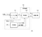
図3は、制御器102の構成例の1つを示す図である。制御器102は、制御偏差Eに基づいて第1信号S1を発生する第1補償器301と、係数を調整可能な演算式に従って制御偏差Eを演算することによって補正信号CSを発生する補正器303とを含む。また、制御器102は、補正信号CSに基づいてニューラルネットワークによって第2信号S2を発生する第2補償器302と、第1信号S1と第2信号S2とに基づいて制御信号MVを発生する演算器306とを含む。
FIG. 3 is a diagram showing one of the configuration examples of the controller 102. The controller 102 includes a first compensator 301 that generates the first signal S1 based on the control deviation E, and a corrector 303 that generates a correction signal CS by calculating the control deviation E according to an arithmetic expression whose coefficient can be adjusted. And include. Further, the controller 102 is an operation to generate a control signal MV based on the second compensator 302 that generates the second signal S2 by the neural network based on the correction signal CS, and the first signal S1 and the second signal S2. Includes vessel 306.
補正器303は、第1調整部303a、第2調整部303bを含む複数の補正器を有しており、制御状態に応じて使用する調整部(接続される調整部)を選択することができる。制御信号MVは、第1信号S1と第2信号S2との和であり、演算器306は、加算器で構成されうる。また、制御信号MVは、第1信号S1を第2信号S2に基づいて補正した信号である。制御器102は、目標値Rと制御量CVとの差分である制御偏差Eを発生する減算器305を含む。制御量CVは、制御対象103が備えている不図示のセンサ等により計測されることで取得される。また、第1信号S1に基づいて制御対象103を制御した結果である制御量と目標値Rとの差に比べて、制御信号MVに基づいて制御対象103を制御した結果である制御量と目標値Rとの差の方が小さい。
The corrector 303 has a plurality of correctors including a first adjustment unit 303a and a second adjustment unit 303b, and an adjustment unit (connected adjustment unit) to be used can be selected according to a control state. .. The control signal MV is the sum of the first signal S1 and the second signal S2, and the arithmetic unit 306 may be composed of an adder. Further, the control signal MV is a signal obtained by correcting the first signal S1 based on the second signal S2. The controller 102 includes a subtractor 305 that generates a control deviation E, which is a difference between the target value R and the control amount CV. The controlled variable CV is acquired by being measured by a sensor (not shown) included in the controlled object 103. Further, the control amount and the target which are the results of controlling the control target 103 based on the control signal MV are compared with the difference between the control amount and the target value R which are the result of controlling the control target 103 based on the first signal S1. The difference from the value R is smaller.
制御器102は、動作履歴記録部304を更に含む。図2における学習部201は、図3における第2補償器302のニューラルネットワークのパラメータ値を決定するための学習を行うように構成される。学習部201による学習のために、動作履歴記録部304は、学習部201による学習に要する動作履歴を記録し、記録した動作履歴を学習部201に提供する。動作履歴とは、例えば、第2補償器302に対する入力データである補正信号CSと、第2補償器302の出力データである第2信号S2であるが、制御偏差と第2補償器302の出力データである第2信号S2であってもよいし、他のデータであってもよい。第1調整部303a、第2調整部303bは任意のパラメータを初期値として学習を行うことができる。
The controller 102 further includes an operation history recording unit 304. The learning unit 201 in FIG. 2 is configured to perform learning for determining the parameter value of the neural network of the second compensator 302 in FIG. For learning by the learning unit 201, the operation history recording unit 304 records the operation history required for learning by the learning unit 201, and provides the recorded operation history to the learning unit 201. The operation history is, for example, a correction signal CS which is input data to the second compensator 302 and a second signal S2 which is output data of the second compensator 302, but the control deviation and the output of the second compensator 302. It may be the second signal S2 which is data, or it may be other data. The first adjustment unit 303a and the second adjustment unit 303b can perform learning with arbitrary parameters as initial values.
以下の実施例1~5において、補正器303の構成例を説明する。実施例1~5では、補正器303が制御偏差Eに基づいて補正信号CSを生成するために使用する演算式の例を示す。演算式は、例えば、単項式または多項式でありうる。
In the following Examples 1 to 5, a configuration example of the corrector 303 will be described. In Examples 1 to 5, an example of an arithmetic expression used by the corrector 303 to generate a correction signal CS based on the control deviation E is shown. The arithmetic expression can be, for example, a monomial expression or a polynomial.
(実施例1)
実施例1において、第1調整部303a、第2調整部303bは、以下の式(1)で表される制御特性を有する。ここで、補正器303に対する入力(E)をx、補正器303の出力(CS)をy、任意の係数(定数)をKpとする。
(Example 1)
In the first embodiment, the first adjusting unit 303a and the second adjusting unit 303b have the control characteristics represented by the following equation (1). Here, the input (E) to the corrector 303 is x, the output (CS) of the corrector 303 is y, and an arbitrary coefficient (constant) is Kp.
(実施例2)
実施例2において、第1調整部303a、第2調整部303bは、以下の式(2)で表される制御特性を有する。ここで、補正器303に対する入力(E)をx、補正器303の出力(CS)をy、時刻をt、任意の係数(定数)をKiとする。なお、積分は複数回行ってもよい。積分はある時間区間の定積分でもよいし、不定積分でもよい。
(Example 2)
In the second embodiment, the first adjusting unit 303a and the second adjusting unit 303b have the control characteristics represented by the following equation (2). Here, the input (E) to the corrector 303 is x, the output (CS) of the corrector 303 is y, the time is t, and an arbitrary coefficient (constant) is Ki. The integration may be performed a plurality of times. The integral may be a definite integral in a certain time interval or an indefinite integral.
(実施例3)
実施例3において、第1調整部303a、第2調整部303bは、以下の式(3)で表される制御特性を有する。ここで、補正器303に対する入力(E)をx、補正器303の出力(CS)をy、時刻をt、任意の係数(定数)Kdとする。なお、微分は複数回行ってもよい。
(Example 3)
In the third embodiment, the first adjusting unit 303a and the second adjusting unit 303b have the control characteristics represented by the following equation (3). Here, the input (E) to the corrector 303 is x, the output (CS) of the corrector 303 is y, the time is t, and an arbitrary coefficient (constant) Kd is used. The differentiation may be performed a plurality of times.
(実施例4)
実施例4において、第1調整部303a、第2調整部303bは、以下の式(4)で表される制御特性を有する。ここで、補正器303に対する入力(E)をx、補正器303の出力(CS)をy、任意の係数(定数)をKp、Ki、Kdとする。なお、積分および微分は複数回行ってもよい。
(Example 4)
In the fourth embodiment, the first adjusting unit 303a and the second adjusting unit 303b have the control characteristics represented by the following equation (4). Here, the input (E) to the corrector 303 is x, the output (CS) of the corrector 303 is y, and the arbitrary coefficients (constants) are Kp, Ki, and Kd. The integration and differentiation may be performed a plurality of times.
(実施例5)
実施例5において、第1調整部303a、第2調整部303bは、以下の式(5)の演算式で表される制御特性を有する。ここで、補正器303に対する入力(E)をx、補正器303の出力(CS)をy、多重積分の積分階数をn、微分階数をm、任意の係数(定数)をKp、n重積分のときの任意の係数(定数)をKi_n、m階微分のときの任意の定数をKd_mとする。
(Example 5)
In the fifth embodiment, the first adjusting unit 303a and the second adjusting unit 303b have control characteristics represented by the arithmetic expression of the following equation (5). Here, the input (E) to the corrector 303 is x, the output (CS) of the corrector 303 is y, the integral order of the multiple integral is n, the derivative order is m, and any coefficient (constant) is Kp, n multiple integral. Let Ki_n be an arbitrary coefficient (constant) at the time of, and Kd_m be an arbitrary constant at the time of the m-th order derivative.
実施例1~5は、補正器303が補正信号CSを生成するために使用する演算式が、制御偏差Eに比例する項、積分を行う項、および、微分を行う項の、少なくとも1つを含む例として理解されうる。
In the first to fifth embodiments, the arithmetic expression used by the corrector 303 to generate the correction signal CS has at least one of a term proportional to the control deviation E, a term for integrating, and a term for differentiating. It can be understood as an example that includes.
実施例1~5で挙げられた演算式の係数(定数)Kp、Ki、Kd、Ki_n、Kd_mは、補正器303の調整可能なパラメータの例である。第1調整部303a、第2調整部303bは、あらかじめ想定される制御状態の変化に応じて、実施例1~5のいずれかを用いた最適なパラメータを決定しておく。制御状態とは、例えば、同期制御の切り替えや制御器の切り替え、動作パターンの切り替え、温度や騒音、床振動などの環境や外乱の変化などである。制御状態に応じた第1調整部303a、第2調整部303bを選択することで、最適な制御特性を得ることができる。補正器を複数構成することによる調整時間は、ニューラルネットワークを複数構成することによる調整時間よりも短いため、時間短縮の観点で有利である。
The coefficients (constants) Kp, Ki, Kd, Ki_n, and Kd_m of the arithmetic expressions given in Examples 1 to 5 are examples of adjustable parameters of the corrector 303. The first adjusting unit 303a and the second adjusting unit 303b determine the optimum parameters using any one of the first to fifth embodiments according to the change in the control state assumed in advance. The control state is, for example, switching of synchronous control, switching of controllers, switching of operation patterns, changes in environment and disturbance such as temperature, noise, and floor vibration. Optimal control characteristics can be obtained by selecting the first adjustment unit 303a and the second adjustment unit 303b according to the control state. Since the adjustment time due to the configuration of a plurality of correctors is shorter than the adjustment time due to the configuration of a plurality of neural networks, it is advantageous from the viewpoint of time reduction.
また、システムSSの動作中に制御対象103の状態や外乱環境が変化した場合において、実施例1~5として例示された演算式(の係数)の値(パラメータ値)を調整することによって、その変化に対応することができる。補正器303の演算式(の係数)の値の調整に要する時間は、ニューラルネットワークの再学習に要する時間よりも短い。したがって、システムSSの生産性を落とすことなく、制御精度を維持することができる。つまり、補正器303を導入することによって、制御対象103の状態変化や外乱環境の変化に対する寛容性を向上させることができる。
Further, when the state of the controlled object 103 or the disturbance environment changes during the operation of the system SS, the value (parameter value) of the arithmetic expression (coefficient) exemplified as Examples 1 to 5 is adjusted. Can respond to changes. The time required for adjusting the value of the arithmetic expression (coefficient) of the corrector 303 is shorter than the time required for retraining the neural network. Therefore, the control accuracy can be maintained without reducing the productivity of the system SS. That is, by introducing the corrector 303, it is possible to improve the tolerance of the controlled object 103 to changes in the state and the disturbance environment.
(実施例6)
実施例6~8は、制御状態の変化と、補正器303で用いられる調整部の切り替えの関係性について説明する。
(Example 6)
Examples 6 to 8 describe the relationship between the change in the control state and the switching of the adjusting unit used in the corrector 303.
図4は、実施例6における制御器102の構成例を示す図である。実施例6では、図4に示すように、制御対象103a、制御対象103bを含む複数の制御対象に対してそれぞれ個別に制御を行うか、同期させて制御を行うかを切り替えることができる。実施例6における制御状態とは、複数の制御対象を個別に制御するか、同期させて制御するかによって定まる状態であり、複数の制御対象を同期制御する否かによって適切な調整部の切り替えを実行する。また、実施例6では、同期制御切り替え部402の状態によって補正器303の切り替えを行う構成となっており、第1調整部303aを使用するか、第2調整部303bを使用するかを選択できる。また、実施例6では、制御対象103aの制御が行われる軸をマスター軸、制御対象103bの制御が行われる軸をスレーブ軸として、スレーブ軸がマスター軸を追従するマスタースレーブ方式と呼ばれる同期制御について説明する。
FIG. 4 is a diagram showing a configuration example of the controller 102 in the sixth embodiment. In the sixth embodiment, as shown in FIG. 4, it is possible to switch whether to control the plurality of control targets including the control target 103a and the control target 103b individually or in synchronization with each other. The control state in the sixth embodiment is a state determined by whether a plurality of control targets are individually controlled or synchronously controlled, and an appropriate adjustment unit is switched depending on whether or not the plurality of control targets are synchronously controlled. Run. Further, in the sixth embodiment, the corrector 303 is switched according to the state of the synchronous control switching unit 402, and it is possible to select whether to use the first adjusting unit 303a or the second adjusting unit 303b. .. Further, in the sixth embodiment, the axis in which the control target 103a is controlled is set as the master axis, the axis in which the control target 103b is controlled is set as the slave axis, and the slave axis follows the master axis. explain.
制御器102は、制御対象103が備えている不図示のセンサで計測した制御対象103a、103bそれぞれの制御量CVa、CVbを取得して、それぞれの目標値Ra、Rbとの差分をそれぞれ制御偏差Ea、Ebとして計算する。
The controller 102 acquires the control quantities CVa and CVb of the control targets 103a and 103b measured by the sensors (not shown) included in the control target 103, and sets the difference from the target values Ra and Rb, respectively, as the control deviation. Calculated as Ea and Eb.
制御偏差Eaは制御器301aに入力される。制御器301bと、制御器301bと並列に構成されているニューラルネットワーク302の前段に設けられた補正器303への入力は、制御対象103aと制御対象103bとを同期制御をするか否かで切り替えることができる。補正器303への入力は、制御対象103aと制御対象103bとの同期制御を切り替える同期制御切り替え部402によって切り替えられる制御偏差Ebもしくは、制御偏差Ebと制御偏差Eaの差分である同期偏差Ecを選択することができる。補正器303の出力は、同期制御切り替え部402の状態に応じて、第1調整部303aを使用するか、第2調整部303bを使用するかを選択することができる。
The control deviation Ea is input to the controller 301a. The input to the controller 301b and the corrector 303 provided in front of the neural network 302 configured in parallel with the controller 301b is switched depending on whether or not the control target 103a and the control target 103b are synchronously controlled. be able to. For the input to the corrector 303, select the control deviation Eb switched by the synchronization control switching unit 402 that switches the synchronization control between the control target 103a and the control target 103b, or the synchronization deviation Ec that is the difference between the control deviation Eb and the control deviation Ea. can do. For the output of the corrector 303, it is possible to select whether to use the first adjustment unit 303a or the second adjustment unit 303b according to the state of the synchronization control switching unit 402.
実施例6の具体例として、例えば、露光装置に適用する場合、プレートステージとマスクステージを同期させているときと、それ以外の動作をするときとでは、異なる調整部を選択してもよい。この時、第1調整部303aと第2調整部303bは、プレートステージとマスクステージが同期しているときと、それ以外の動作をするときとにおいて、それぞれパラメータが最適化されている。同期制御切り替え部402の状態によって選択された第1調整部303a、第2調整部303bの出力はニューラルネットワーク302(第2補償器)に入力される。補償器301aの出力を制御信号MVaとする。補償器301bの出力とニューラルネットワーク302の出力を加算して、制御信号MVbとする。制御器102は、制御信号MVa、MVbをそれぞれ制御対象103a、103bに出力する。
As a specific example of the sixth embodiment, for example, when applied to an exposure apparatus, different adjustment units may be selected depending on whether the plate stage and the mask stage are synchronized with each other and when other operations are performed. At this time, the parameters of the first adjusting unit 303a and the second adjusting unit 303b are optimized when the plate stage and the mask stage are synchronized and when the other operations are performed. The outputs of the first adjustment unit 303a and the second adjustment unit 303b selected according to the state of the synchronization control switching unit 402 are input to the neural network 302 (second compensator). The output of the compensator 301a is a control signal MVa. The output of the compensator 301b and the output of the neural network 302 are added to obtain a control signal MVb. The controller 102 outputs the control signals MVa and MVb to the controlled objects 103a and 103b, respectively.
第1調整部303a、第2調整部303bは、同期制御切り替え部402の状態に応じて、実施例1~5のいずれかを用いた最適なパラメータを決定しておく。同期制御切り替え部402の状態に応じた第1調整部303a、第2調整部303bを選択することで、最適な制御特性を得ることができる。
The first adjusting unit 303a and the second adjusting unit 303b determine the optimum parameters using any one of Examples 1 to 5 according to the state of the synchronization control switching unit 402. Optimal control characteristics can be obtained by selecting the first adjustment unit 303a and the second adjustment unit 303b according to the state of the synchronization control switching unit 402.
補正器303が複数の調整部から最適な調整部を選択する構成となっていることによる調整時間の増加は、ニューラルネットワークを複数構成することによる調整時間の増加よりも短い。また、実施例1~5のいずれかを用いての運用中に制御対象103の状態や外乱環境が変化した場合において、実施例1~5のパラメータを調整することでその変化に対応することができる。第1調整部303a、第2調整部303bの調整に要する時間はニューラルネットワークの再学習に要する時間よりも短い。実施例6において、制御対象の状態や外乱環境に合わせた複数の補償を行う場合においても、演算時間や学習時間の増加を抑えることができ、制御対象の状態変化や外乱環境に変化が生じても、適正な制御特性を短時間で調整することができる。
The increase in the adjustment time due to the configuration in which the corrector 303 selects the optimum adjustment unit from the plurality of adjustment units is shorter than the increase in the adjustment time due to the configuration of a plurality of neural networks. Further, when the state of the controlled object 103 or the disturbance environment changes during the operation using any of the first to fifth embodiments, it is possible to cope with the change by adjusting the parameters of the first to fifth embodiments. can. The time required for adjustment of the first adjustment unit 303a and the second adjustment unit 303b is shorter than the time required for re-learning the neural network. In the sixth embodiment, even when a plurality of compensations are performed according to the state of the controlled object and the disturbance environment, the increase in the calculation time and the learning time can be suppressed, and the state change of the controlled object and the disturbance environment occur. However, the appropriate control characteristics can be adjusted in a short time.
(実施例7)
図5は、実施例7における制御器102の構成例を示す図である。実施例7では、制御対象103の状態や動作に応じて補償器301の切り替えを行う構成となっており、補償器301aを使用するか、補償器301bを使用するかを選択できる。実施例7における制御状態とは、複数の補償器のうちどの補償器を使用するかによって定まる状態であり、補償器301aを使用するか、補償器301bを使用するかによって調整部の切り替えを実行する。また、実施例7では、補償器301の状態によって補正器303の切り替えを行う構成となっており、第1調整部303aを使用するか、第2調整部303bを使用するかを選択できる。
(Example 7)
FIG. 5 is a diagram showing a configuration example of the controller 102 in the seventh embodiment. In the seventh embodiment, the compensator 301 is switched according to the state and operation of the controlled object 103, and it is possible to select whether to use the compensator 301a or the compensator 301b. The control state in the seventh embodiment is a state determined by which of the plurality of compensators is used, and the adjustment unit is switched depending on whether the compensator 301a or the compensator 301b is used. do. Further, in the seventh embodiment, the compensator 303 is switched depending on the state of the compensator 301, and it is possible to select whether to use the first adjusting unit 303a or the second adjusting unit 303b.
実施例7の具体例として、例えば、露光装置に適用する場合、プレートステージの露光動作時には補償器301aを、プレート搬送動作においては補償器301bを使用するといったゲインの切り替えが生じるときに適用してもよい。即ち、制御対象103のゲインの切り替えが生じているか否かに基づいて複数の調整部から制御偏差Eの補正に用いる調整部が選択されればよい。この時、第1調整部303aと第2調整部303bは、補償器301a、補償器301bに対して、実施例1~5のいずれかを用いた最適なパラメータを決定しておく。補償器301の状態に応じた第1調整部303a、第2調整部303bを選択することで、最適な制御特性を得ることができる。
As a specific example of the seventh embodiment, for example, when applied to an exposure apparatus, the compensator 301a is used during the exposure operation of the plate stage, and the compensator 301b is used during the plate transfer operation. May be good. That is, the adjustment unit used for correcting the control deviation E may be selected from the plurality of adjustment units based on whether or not the gain of the control target 103 has been switched. At this time, the first adjusting unit 303a and the second adjusting unit 303b determine the optimum parameters for the compensator 301a and the compensator 301b using any one of the first to fifth embodiments. Optimal control characteristics can be obtained by selecting the first adjustment unit 303a and the second adjustment unit 303b according to the state of the compensator 301.
補正器303が複数の調整部から最適な調整部を選択する構成となっていることによる調整時間の増加は、ニューラルネットワークを複数構成することによる調整時間の増加よりも短い。また、実施例1~5のいずれかを用いての運用中に制御対象103の状態や外乱環境が変化した場合において、実施例1~5のパラメータを調整することでその変化に対応することができる。第1調整部303a、第2調整部303bの調整に要する時間はニューラルネットワークの再学習に要する時間よりも短い。実施例7において、制御対象の状態や外乱環境に合わせた複数の補償を行う場合においても、演算時間や学習時間の増加を抑えることができ、制御対象の状態変化や外乱環境に変化が生じても、適正な制御特性を短時間で調整することができる。
The increase in the adjustment time due to the configuration in which the corrector 303 selects the optimum adjustment unit from the plurality of adjustment units is shorter than the increase in the adjustment time due to the configuration of a plurality of neural networks. Further, when the state of the controlled object 103 or the disturbance environment changes during the operation using any of the first to fifth embodiments, it is possible to cope with the change by adjusting the parameters of the first to fifth embodiments. can. The time required for adjustment of the first adjustment unit 303a and the second adjustment unit 303b is shorter than the time required for re-learning the neural network. In the seventh embodiment, even when a plurality of compensations are performed according to the state of the controlled object and the disturbance environment, the increase in the calculation time and the learning time can be suppressed, and the state change of the controlled object and the disturbance environment occur. However, the appropriate control characteristics can be adjusted in a short time.
(実施例8)
図6は、実施例8における制御器102の構成例を示す図である。実施例8における制御状態とは、制御対象の動作パターン403が変化しているか否かによって定まる状態である。動作パターン403の具体例については、後述する。実施例8では、動作パターン403の状態に応じて調整部の切り替えを行う構成となっており、第1調整部303aを使用するか、第2調整部303bを使用するかを選択できる。
(Example 8)
FIG. 6 is a diagram showing a configuration example of the controller 102 in the eighth embodiment. The control state in the eighth embodiment is a state determined by whether or not the operation pattern 403 to be controlled is changed. A specific example of the operation pattern 403 will be described later. In the eighth embodiment, the adjustment unit is switched according to the state of the operation pattern 403, and it is possible to select whether to use the first adjustment unit 303a or the second adjustment unit 303b.
実施例7の具体例として、例えば、露光装置等に用いられるステージ装置に適用する場合、ステージの駆動時の加速区間と、それ以外の動作パターンで切り替えて適用してもよい。この時、第1調整部303aと第2調整部303bは、制御対象103の動作パターン403の状態に応じて、実施例1~5のいずれかを用いた最適なパラメータを決定しておく。動作パターン403の状態に応じた第1調整部303a、第2調整部303bを選択することで、最適な制御特性を得ることができる。
As a specific example of the seventh embodiment, for example, when it is applied to a stage device used for an exposure device or the like, it may be applied by switching between an acceleration section when the stage is driven and an operation pattern other than that. At this time, the first adjusting unit 303a and the second adjusting unit 303b determine the optimum parameters using any of the first to fifth embodiments according to the state of the operation pattern 403 of the controlled object 103. Optimal control characteristics can be obtained by selecting the first adjustment unit 303a and the second adjustment unit 303b according to the state of the operation pattern 403.
補正器303が複数の調整部から最適な調整部を選択する構成となっていることによる調整時間の増加は、ニューラルネットワークを複数構成することによる調整時間の増加よりも短い。また、実施例1~5のいずれかを用いての運用中に制御対象103の状態や外乱環境が変化した場合において、実施例1~5のパラメータを調整することでその変化に対応することができる。第1調整部303a、第2調整部303bの調整に要する時間はニューラルネットワークの再学習に要する時間よりも短い。実施例8において、制御対象の状態や外乱環境に合わせた複数の補償を行う場合においても、演算時間や学習時間の増加を抑えることができ、制御対象の状態変化や外乱環境に変化が生じても、適正な制御特性を短時間で調整することができる。
The increase in the adjustment time due to the configuration in which the corrector 303 selects the optimum adjustment unit from the plurality of adjustment units is shorter than the increase in the adjustment time due to the configuration of a plurality of neural networks. Further, when the state of the controlled object 103 or the disturbance environment changes during the operation using any of the first to fifth embodiments, it is possible to cope with the change by adjusting the parameters of the first to fifth embodiments. can. The time required for adjustment of the first adjustment unit 303a and the second adjustment unit 303b is shorter than the time required for re-learning the neural network. In the eighth embodiment, even when a plurality of compensations are performed according to the state of the controlled object and the disturbance environment, the increase in the calculation time and the learning time can be suppressed, and the state change of the controlled object and the disturbance environment occur. However, the appropriate control characteristics can be adjusted in a short time.
図7に例示されるように、制御装置100は、第1調整部303aを使用するか、第2調整部を使用するかを選択する設定部202を備えてもよい。また、設定部202は、補正器303のパラメータ値を設定する役割を有していてもよい。
As illustrated in FIG. 7, the control device 100 may include a setting unit 202 for selecting whether to use the first adjustment unit 303a or the second adjustment unit. Further, the setting unit 202 may have a role of setting the parameter value of the corrector 303.
設定部202は、調整部の切り替えやパラメータ値を調整するための調整処理を実行し、この調整処理によって調整部の切り替えやパラメータ値を決定し設定してもよいし、ユーザからの指令に基づいて調整部の切り替えやパラメータ値を設定してもよい。前者においては、設定部202は、制御器102の動作を確認するための確認シーケンスをシーケンス部101に送り、この確認シーケンスに基づいてシーケンス部101に目標値Rを生成させうる。そして、設定部202は、その目標値Rに基づいて動作する制御器102から動作履歴(例えば、制御偏差)を取得し、その動作履歴に基づいて補正器303の切り替えの必要性の有無やパラメータ値を決定しうる。このような機能を有する設定部202は、補正器303の切り替えやパラメータ値を調整する調整部として理解することができる。
The setting unit 202 may execute an adjustment process for switching the adjustment unit or adjusting the parameter value, and may determine and set the switching of the adjustment unit or the parameter value by this adjustment process, or based on a command from the user. You may switch the adjustment unit or set the parameter value. In the former, the setting unit 202 may send a confirmation sequence for confirming the operation of the controller 102 to the sequence unit 101, and cause the sequence unit 101 to generate the target value R based on this confirmation sequence. Then, the setting unit 202 acquires an operation history (for example, a control deviation) from the controller 102 that operates based on the target value R, and based on the operation history, whether or not there is a need to switch the corrector 303 and parameters. The value can be determined. The setting unit 202 having such a function can be understood as an adjusting unit for switching the corrector 303 and adjusting the parameter value.
設定部202は、シーケンス部101が生産シーケンスに基づいて目標値Rを生成する生産時に、制御器102から動作履歴(例えば、制御偏差)を取得し、その動作履歴に基づいて補正器303のパラメータ値の調整を実行するかどうかを決定してもよい。あるいは、シーケンス部101が生産シーケンスに基づいて目標値Rを生成する生産時において設定部202による補正器303のパラメータ値の調整を実行するかどうかを判断する判断部が設定部202とは別に設けられてもよい。
The setting unit 202 acquires an operation history (for example, control deviation) from the controller 102 at the time of production in which the sequence unit 101 generates a target value R based on the production sequence, and the parameter of the corrector 303 is based on the operation history. You may decide whether to perform value adjustments. Alternatively, a determination unit for determining whether to adjust the parameter value of the corrector 303 by the setting unit 202 at the time of production in which the sequence unit 101 generates the target value R based on the production sequence is provided separately from the setting unit 202. May be done.
次に本実施形態におけるシステムによって生産が行われる例について説明する。図8は、本実施形態のシステムSSを生産装置に適用した場合のシステムSSの動作例である。
Next, an example in which production is performed by the system in this embodiment will be described. FIG. 8 is an operation example of the system SS when the system SS of the present embodiment is applied to the production apparatus.
工程S501では、シーケンス部101が、与えられた生産シーケンスに基づいて目標値Rを生成し、制御装置100あるいは制御器102に提供する。制御装置100あるいは制御器102は、その目標値Rに基づいて制御対象103を制御する。
In step S501, the sequence unit 101 generates a target value R based on a given production sequence and provides it to the control device 100 or the controller 102. The control device 100 or the controller 102 controls the control target 103 based on the target value R.
工程S502では、設定部202は、工程S501における制御器102の動作履歴(例えば、制御偏差)を取得する。
In the process S502, the setting unit 202 acquires the operation history (for example, control deviation) of the controller 102 in the process S501.
工程S503では、設定部202が、工程S502で取得した動作履歴に基づいて、調整部の切り替えや、パラメータ値の調整(あるいは再調整)等の補正器303の調整を実行するかどうかを判断しうる。設定部202は、例えば、動作履歴が所定条件を満たす場合に、調整部の切り替えパラメータ値の調整(あるいは再調整)を実行すると判断することができる。所定条件とは、生産を停止させるべき条件であり、例えば、動作履歴として取得した制御偏差が規定値を超える場合に補正器303の調整が必要であると判断される。そして、設定部202による補正器303の調整を実行する場合には工程S504に進み、そうでない場合には工程S505に進む。
In the process S503, the setting unit 202 determines whether to perform adjustment of the corrector 303 such as switching of the adjustment unit and adjustment (or readjustment) of the parameter value based on the operation history acquired in the process S502. sell. For example, the setting unit 202 can determine that the adjustment (or readjustment) of the switching parameter value of the adjustment unit is executed when the operation history satisfies a predetermined condition. The predetermined condition is a condition for stopping production. For example, when the control deviation acquired as the operation history exceeds the specified value, it is determined that the correction device 303 needs to be adjusted. Then, when the adjustment of the corrector 303 is executed by the setting unit 202, the process proceeds to step S504, and when not, the process proceeds to step S505.
工程S504では、設定部202は、補正器303の調整を実行する。この調整は、第2補償器302のパラメータ値が従前の状態に維持された状態でなされ、この調整によって、例えば、補正器303のパラメータ値(係数)が再設定される。
In step S504, the setting unit 202 executes the adjustment of the corrector 303. This adjustment is made in a state where the parameter value of the second compensator 302 is maintained in the previous state, and by this adjustment, for example, the parameter value (coefficient) of the corrector 303 is reset.
工程S505では、シーケンス部101は、生産シーケンスに従う生産を終了するかどうかを判断し、終了しない場合には工程S501に戻り、終了する場合には生産を終了する。以上の処理によれば、生産を停止させるべき状態になった場合においても、速やかに補正器303のパラメータ値を調整し、生産の中断を最小限に抑えながら生産を再開させることができる。
In the process S505, the sequence unit 101 determines whether to end the production according to the production sequence, returns to the process S501 if it does not end, and ends the production if it ends. According to the above processing, even when the production should be stopped, the parameter value of the corrector 303 can be promptly adjusted and the production can be restarted while minimizing the interruption of the production.
工程S504では、設定部202は、確認シーケンスをシーケンス部101に送り、シーケンス部101に確認シーケンスを実行させ、確認シーケンスにおける動作履歴(例えば、制御偏差)を制御器102から取得しうる。そして、設定部202は、その動作履歴の周波数解析を行い、その結果に基づいて、改善すべき周波数を決定し、その周波数における制御偏差が規定値以内になるように補正器303のパラメータ値を決定しうる。工程S504の更に具体的な例については、第2実施形態において説明する。
In step S504, the setting unit 202 sends the confirmation sequence to the sequence unit 101, causes the sequence unit 101 to execute the confirmation sequence, and can acquire the operation history (for example, control deviation) in the confirmation sequence from the controller 102. Then, the setting unit 202 performs frequency analysis of the operation history, determines a frequency to be improved based on the result, and sets the parameter value of the corrector 303 so that the control deviation at that frequency is within the specified value. Can be decided. A more specific example of step S504 will be described in the second embodiment.
図9には、外乱抑圧特性の計測結果を例示している図である。図2における制御信号MVとして正弦波を入力したときの制御偏差を出力としたときの周波数応答を計測した結果のことを外乱抑圧特性と呼ぶ。図9において、横軸は周波数、縦軸は外乱抑圧特性のゲインを表す。外乱抑圧特性は、制御信号MVに外乱が加算された場合の制御偏差Eの周波数応答を表すため、ゲインが大きいことは、外乱を抑圧する効果が低いことを示す。一方、ゲインが小さいことは、外乱を抑圧する効果が高いことを示す。図9において、破線は、調整前の外乱抑圧特性を示しており、実線は調整後の外乱抑圧特性を示している。
FIG. 9 is a diagram illustrating the measurement results of the disturbance suppression characteristics. The result of measuring the frequency response when the control deviation when a sine wave is input as the control signal MV in FIG. 2 is used as an output is called a disturbance suppression characteristic. In FIG. 9, the horizontal axis represents the frequency and the vertical axis represents the gain of the disturbance suppression characteristic. Since the disturbance suppression characteristic represents the frequency response of the control deviation E when the disturbance is added to the control signal MV, a large gain indicates that the effect of suppressing the disturbance is low. On the other hand, a small gain indicates that the effect of suppressing disturbance is high. In FIG. 9, the broken line shows the disturbance suppression characteristic before adjustment, and the solid line shows the disturbance suppression characteristic after adjustment.
図9における一点鎖線で示された周波数を、外乱抑圧特性を改善すべき周波数として定めて工程S504を実行すると、例えば、実線で示されるような外乱抑圧特性を得ることができる。改善すべき周波数において外乱抑圧特性のゲイン小さくなり、外乱抑圧特性が向上していることが分かる。実施例1~8で、ニューラルネットワークの前段に設けた補正器303のパラメータ調整を行う場合、図9に示す外乱抑圧特性を指標にパラメータ調整を行ってもよい。
When the frequency shown by the alternate long and short dash line in FIG. 9 is set as the frequency at which the disturbance suppression characteristic should be improved and the step S504 is executed, for example, the disturbance suppression characteristic as shown by the solid line can be obtained. It can be seen that the gain of the disturbance suppression characteristic becomes smaller at the frequency to be improved, and the disturbance suppression characteristic is improved. In Examples 1 to 8, when the parameters of the corrector 303 provided in the front stage of the neural network are adjusted, the parameters may be adjusted using the disturbance suppression characteristic shown in FIG. 9 as an index.
<第2実施形態>
本実施形態では、第1実施形態で説明した制御システムSSをステージ制御装置800に適用する例について説明する。本実施形態として言及しない事項は、第1実施形態に従う。図10は、図1で示した制御システムSSをステージ制御装置800に適用したときのハードウェア構成を示す図である。
<Second Embodiment>
In this embodiment, an example of applying the control system SS described in the first embodiment to the stage control device 800 will be described. Matters not mentioned as this embodiment follow the first embodiment. FIG. 10 is a diagram showing a hardware configuration when the control system SS shown in FIG. 1 is applied to the stage control device 800.
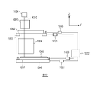
ステージ制御装置800は、基板等の物体の位置を制御するために、前記物体をステージ804上に保持した状態でステージ804を制御するように構成されている。ステージ制御装置800は、制御基板801、電流ドライバ802、モータ803、ステージ804およびセンサ805を備える。制御基板801は、第1実施形態のシステムSSにおける制御装置100または制御器102に対応する。電流ドライバ802、モータ803、ステージ804およびセンサ805は、第1実施形態のシステムSSにおける制御対象103に対応する。ただし、電流ドライバ802は、制御基板801に組み込まれてもよい。図10には図示されていないが、ステージ制御装置800は、シーケンス部101、学習部201、設定部202を備えうる。
The stage control device 800 is configured to control the stage 804 while holding the object on the stage 804 in order to control the position of an object such as a substrate. The stage control device 800 includes a control board 801, a current driver 802, a motor 803, a stage 804, and a sensor 805. The control board 801 corresponds to the control device 100 or the controller 102 in the system SS of the first embodiment. The current driver 802, the motor 803, the stage 804, and the sensor 805 correspond to the controlled object 103 in the system SS of the first embodiment. However, the current driver 802 may be incorporated in the control board 801. Although not shown in FIG. 10, the stage control device 800 may include a sequence unit 101, a learning unit 201, and a setting unit 202.
制御基板801には、シーケンス部101から目標値としての位置目標値が供給されうる。制御基板801は、シーケンス部101から供給される位置目標値とセンサ805から供給される位置情報とに基づいて、制御信号としての電流指令を発生し、電流ドライバ802に供給しうる。また、制御基板801は、動作履歴をシーケンス部101に供給しうる。
The control board 801 can be supplied with a position target value as a target value from the sequence unit 101. The control board 801 can generate a current command as a control signal and supply it to the current driver 802 based on the position target value supplied from the sequence unit 101 and the position information supplied from the sensor 805. Further, the control board 801 can supply the operation history to the sequence unit 101.
電流ドライバ802は、電流指令に従った電流をモータ803に供給しうる。モータ803は、電流ドライバ802から供給される電流を推力に変換し、その推力でステージ804を駆動するアクチュエータでありうる。ステージ804は、例えば、プレートまたはマスク等の物体を保持しうる。センサ805は、ステージ804の位置を検出し、それによって得られた位置情報を制御基板801に供給しうる。
The current driver 802 can supply the current according to the current command to the motor 803. The motor 803 may be an actuator that converts the current supplied from the current driver 802 into thrust and drives the stage 804 with the thrust. The stage 804 may hold an object such as a plate or mask. The sensor 805 can detect the position of the stage 804 and supply the position information obtained thereby to the control board 801.
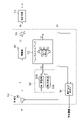
図11には、制御基板801の構成例がブロック線図として示されている。制御基板801は、制御対象としてのステージ804の位置制御偏差Eに基づいて第1信号S1を発生する第1補償器301と、係数を調整可能な演算式に従って制御偏差Eを補正することによって補正信号CSを発生する補正器303とを含みうる。また、制御基板801は、補正信号CSに基づいてニューラルネットワークによって第2信号S2を発生する第2補償器302と、第1信号S1と第2信号S2とに基づいて制御信号として電流指令を発生する演算器306とを含みうる。また、制御基板801は、位置目標値PRと位置情報との差分である制御偏差Eを発生する減算器305を含みうる。
FIG. 11 shows a configuration example of the control board 801 as a block diagram. The control board 801 is corrected by correcting the control deviation E according to the first compensator 301 that generates the first signal S1 based on the position control deviation E of the stage 804 as the control target and the arithmetic expression that can adjust the coefficient. It may include a corrector 303 that generates a signal CS. Further, the control board 801 generates a current command as a control signal based on the second compensator 302 that generates the second signal S2 by the neural network based on the correction signal CS, and the first signal S1 and the second signal S2. It may include the arithmetic unit 306 to be used. Further, the control board 801 may include a subtractor 305 that generates a control deviation E which is a difference between the position target value PR and the position information.
第2実施形態のステージ制御装置100においても、図7で説明した第1実施形態と同様に、学習部201を備えていてもよい。学習部201は、第2補償器302のニューラルネットワークのパラメータ値を決定するための学習を行うように構成されうる。学習部201による学習のために、動作履歴記録部304は、学習部201による学習に要する動作履歴を記録し、記録した動作履歴を学習部201に提供しうる。動作履歴は、例えば、第2補償器302に対する入力データである補正信号CSと、第2補償器302の出力データである第2信号S2でありうるが、他のデータでもよい。
The stage control device 100 of the second embodiment may also include the learning unit 201 as in the first embodiment described with reference to FIG. 7. The learning unit 201 may be configured to perform learning for determining the parameter value of the neural network of the second compensator 302. For learning by the learning unit 201, the operation history recording unit 304 may record the operation history required for learning by the learning unit 201 and provide the recorded operation history to the learning unit 201. The operation history may be, for example, a correction signal CS which is input data for the second compensator 302 and a second signal S2 which is output data of the second compensator 302, but other data may be used.
第2実施形態のステージ制御装置100は、設定部202を備えることができる。設定部202は、補正器303のパラメータ値を調整するための調整処理を実行し、この調整処理によって補正器303のパラメータ値を決定し設定してもよいし、ユーザからの指令に基づいて補正器303のパラメータ値を設定してもよい。
The stage control device 100 of the second embodiment can include a setting unit 202. The setting unit 202 may execute an adjustment process for adjusting the parameter value of the corrector 303, determine and set the parameter value of the corrector 303 by this adjustment process, or correct based on a command from the user. The parameter value of the device 303 may be set.
図8を援用して、第2実施形態のステージ制御装置800を生産装置に適用した場合のステージ装置800の動作を例示的に説明する。工程S501では、シーケンス部101が、与えられた生産シーケンスに基づいて位置目標値PRを生成し、ステージ制御装置800に提供しうる。ステージ制御装置800は、その位置目標値PRに基づいてステージ804の位置を制御する。
With reference to FIG. 8, the operation of the stage device 800 when the stage control device 800 of the second embodiment is applied to the production device will be exemplified. In step S501, the sequence unit 101 can generate a position target value PR based on a given production sequence and provide it to the stage control device 800. The stage control device 800 controls the position of the stage 804 based on the position target value PR.
工程S502では、設定部202が、工程S501における制御基板801の動作履歴(例えば、制御偏差)を取得する。
In the process S502, the setting unit 202 acquires the operation history (for example, control deviation) of the control board 801 in the process S501.
工程S503では、設定部202が、工程S502で取得した動作履歴に基づいて、調整部の切り替えや、パラメータ値の調整(あるいは再調整)等の補正器303の調整を実行するかどうかを判断しうる。設定部202は、例えば、動作履歴が所定条件を満たす場合に、補正器303の調整を実行すると判断することができる。所定条件とは、生産を停止させるべき条件であり、例えば、ステージ804の等速駆動中の位置制御偏差の最大値が予め決められた規定値を超える場合に補正器303の調整が必要であると判断される。そして、設定部202による補正器303の調整を実行する場合には工程S504に進み、そうでない場合には工程S505に進む。
In the process S503, the setting unit 202 determines whether to perform adjustment of the corrector 303 such as switching of the adjustment unit and adjustment (or readjustment) of the parameter value based on the operation history acquired in the process S502. sell. For example, the setting unit 202 can determine that the adjustment of the corrector 303 is executed when the operation history satisfies a predetermined condition. The predetermined condition is a condition for stopping production. For example, when the maximum value of the position control deviation during constant velocity driving of the stage 804 exceeds a predetermined predetermined value, the corrector 303 needs to be adjusted. Is judged. Then, when the adjustment of the corrector 303 is executed by the setting unit 202, the process proceeds to step S504, and when not, the process proceeds to step S505.
工程504では、設定部202は、補正器303の調整を実行しうる。工程S505では、シーケンス部101は、生産シーケンスに従う生産を終了するかどうかを判断し、終了しない場合には工程S501に戻り、終了する場合には生産を終了する。
In step 504, the setting unit 202 can execute the adjustment of the corrector 303. In the process S505, the sequence unit 101 determines whether or not to end the production according to the production sequence, returns to the process S501 if it does not end, and ends the production if it ends.
図12には、工程S504における補正器303の調整のうち、パラメータ値の調整(或いはパラメータ値の再調整)における処理の具体例が示されている。工程S601では、設定部202は、ステージ制御装置800の動作を確認するための確認シーケンスをシーケンス部101に送り、この確認シーケンスに基づいてシーケンス部101に位置目標値PRを生成させうる。工程S602では、設定部202は、その位置目標値PRに基づいて動作する制御器102から動作履歴としての位置制御偏差Eを取得しうる。
FIG. 12 shows a specific example of the processing in the adjustment of the parameter value (or the readjustment of the parameter value) among the adjustments of the corrector 303 in the step S504. In step S601, the setting unit 202 may send a confirmation sequence for confirming the operation of the stage control device 800 to the sequence unit 101, and cause the sequence unit 101 to generate a position target value PR based on this confirmation sequence. In step S602, the setting unit 202 can acquire the position control deviation E as the operation history from the controller 102 that operates based on the position target value PR.
ここで、図13を参照して、パラメータ調整前と後の位置制御偏差Eの変化について説明する。図13は、パラメータ調整の前後における位置制御偏差を例示する図である。図13において、横軸は時間、縦軸は位置制御偏差Eを示している。ここで、点線で示される曲線は、補正器303のパラメータ値を調整する前の位置制御偏差Eであり、位置制御精度が悪化していることを示している。パラメータ値を調整することで、位置制御偏差Eの変動を小さくすることができる。
Here, with reference to FIG. 13, the change in the position control deviation E before and after the parameter adjustment will be described. FIG. 13 is a diagram illustrating the position control deviation before and after the parameter adjustment. In FIG. 13, the horizontal axis represents time and the vertical axis represents position control deviation E. Here, the curve shown by the dotted line is the position control deviation E before adjusting the parameter value of the corrector 303, and indicates that the position control accuracy is deteriorated. By adjusting the parameter value, the fluctuation of the position control deviation E can be reduced.
工程S603では、設定部202は、工程S602で取得した位置制御偏差Eの周波数解析を行いうる。ここで、図14を参照して、パラメータ調整前と後における周波数解析の結果について説明する。図14は、パラメータ調整の前後における周波数解析の結果を例示する図である。図14において、横軸は周波数、縦軸はパワースペクトラムである。点線は、調整前において最大スペクトルを示す周波数を示している。工程S604では、設定部202は、例えば、パワースペクトラムにおいて最大スペクトルを示す周波数を、改善すべき周波数として決定しうる。
In step S603, the setting unit 202 can perform frequency analysis of the position control deviation E acquired in step S602. Here, the results of frequency analysis before and after parameter adjustment will be described with reference to FIG. FIG. 14 is a diagram illustrating the results of frequency analysis before and after parameter adjustment. In FIG. 14, the horizontal axis is frequency and the vertical axis is power spectrum. The dotted line indicates the frequency showing the maximum spectrum before adjustment. In step S604, the setting unit 202 can determine, for example, the frequency showing the maximum spectrum in the power spectrum as the frequency to be improved.
工程S605~S610は、補正器303のパラメータ値を調整する調整処理の具体例である。ここでは、パラメータ値の調整方法として最急降下法を採用して例を説明するが、他の方法が使用されてもよい。工程S605では、設定部202は、nを1に初期化する。例えば、補正器303の演算式が一次積分項、比例項および一次微分項の3項で構成される場合、パラメータ値を調整すべきパラメータは、Ki、Kp、Kdの3個である。n回目の調整におけるパラメータ値pnを以下の式(6)で示す。
Steps S605 to S610 are specific examples of the adjustment process for adjusting the parameter value of the corrector 303. Here, an example is described by adopting the steepest descent method as a method for adjusting the parameter value, but other methods may be used. In step S605, the setting unit 202 initializes n to 1. For example, when the arithmetic expression of the corrector 303 is composed of three terms of a first-order integral term, a proportional term, and a first-order differential term, there are three parameters for which the parameter values should be adjusted: Ki, Kp, and Kd. The parameter value pn in the nth adjustment is shown by the following equation (6).
工程S606では、設定部202は、パラメータ値pnの1回目の調整におけるパラメータ値p1については、任意の初期値を設定することができる。n回目の調整では、後述の式(8)で示されるパラメータ値pnを設定することができる。
In step S606, the setting unit 202 can set an arbitrary initial value for the parameter value p1 in the first adjustment of the parameter value pn. In the nth adjustment, the parameter value pn represented by the equation (8) described later can be set.
パラメータ値pnを調整するための目的関数J(pn)は、例えば、工程S604で決定した周波数における外乱抑圧特性のゲインとされうる。工程S607では、設定部202は、目的関数J(pn)の勾配ベクトルgrad J(pn)を測定しうる。勾配ベクトルgrad J(pn)は、以下の式(7)で与えられうる。勾配ベクトルgrad J(pn)は、パラメータ値pnを構成する各要素Ki-n、Kp-n、Kd-nを微小量だけ変化させることよって計測されうる。
The objective function J (pn) for adjusting the parameter value pn can be, for example, the gain of the disturbance suppression characteristic at the frequency determined in step S604. In step S607, the setting unit 202 can measure the gradient vector grade J (pn) of the objective function J (pn). The gradient vector grade J (pn) can be given by the following equation (7). The gradient vector grade J (pn) can be measured by changing each element Ki-n, Kpn, Kd-n constituting the parameter value pn by a minute amount.
工程S608では、設定部202は、最急降下法の収束判定として、勾配ベクトルgrad J(pn)の各要素の値が規定値以下であるかどうかを判断しうる。勾配ベクトルgrad J(pn)の各要素の値が規定値以下であれば、設定部202は、補正器303のパラメータ値の調整を終了しうる。一方、勾配ベクトルgrad J(pn)の各要素の値が規定値を超えていれば、工程S609において、設定部202は、パラメータ値pn+1を計算しうる。ここで、パラメータ値pn+1は、例えば、0より大きい任意の定数αを使用して、以下の式(8)に従って計算されうる。工程S610では、設定部202は、nの値に1を加算し、工程S606に戻る。
In step S608, the setting unit 202 can determine whether or not the value of each element of the gradient vector grade J (pn) is equal to or less than the specified value as the convergence test of the steepest descent method. If the value of each element of the gradient vector grade J (pn) is equal to or less than the specified value, the setting unit 202 may end the adjustment of the parameter value of the corrector 303. On the other hand, if the value of each element of the gradient vector grade J (pn) exceeds the specified value, the setting unit 202 can calculate the parameter value pn + 1 in step S609. Here, the parameter value pn + 1 can be calculated according to the following equation (8) using, for example, any constant α larger than 0. In step S610, the setting unit 202 adds 1 to the value of n and returns to step S606.
工程S611では、設定部202は、ステージ制御装置800の動作を確認するための確認シーケンスをシーケンス部101に送り、この確認シーケンスに基づいてシーケンス部101に位置目標値PRを生成させうる。工程S612では、設定部202は、その位置目標値PRに基づいて動作する制御器102から動作履歴としての位置制御偏差Eを取得しうる。
In step S611, the setting unit 202 can send a confirmation sequence for confirming the operation of the stage control device 800 to the sequence unit 101, and cause the sequence unit 101 to generate a position target value PR based on this confirmation sequence. In step S612, the setting unit 202 can acquire the position control deviation E as the operation history from the controller 102 that operates based on the position target value PR.
工程S613では、設定部202は、工程S612で取得した位置制御偏差Eが規定値以下であるかどうかを判断し、位置制御偏差Eが規定値を超えていれば工程S601に戻って調整を再実行し、位置制御偏差Eが規定値以下であれば、調整を終了しうる。
In step S613, the setting unit 202 determines whether or not the position control deviation E acquired in step S612 is equal to or less than the specified value, and if the position control deviation E exceeds the specified value, returns to step S601 and repeats the adjustment. If the position control deviation E is equal to or less than the specified value, the adjustment can be completed.
本実施形態によれば、ステージ804を含む制御対象の状態や外乱が変化したような場合において、補正器303のパラメータ値を調整することによって、その変化に対応することができる。例えば、図13の例では、点線で示された位置制御偏差は、実線で示された位置制御偏差まで低減され、制御精度が向上する。
According to the present embodiment, when the state of the controlled object including the stage 804 or the disturbance changes, the change can be dealt with by adjusting the parameter value of the corrector 303. For example, in the example of FIG. 13, the position control deviation shown by the dotted line is reduced to the position control deviation shown by the solid line, and the control accuracy is improved.
式(6)の例では、補正器303のパラメータ数はわずか3個であり、一般的なニューラルネットワークのパラメータ数よりも遥かに少ない。例えば、ディープニューラルネットワークを用いる場合、入力層の次元数を5、隠れ層の次元数を32の2段、出力層の次元数を8とすると、パラメータ数は1545個となる。これら1545個のパラメータの値を再学習によって決定するよりも、補正器303のパラメータ値を調整する方が短時間で調整を終えることができる。したがって、ステージ制御装置800の生産性を落とすことなく、制御精度を維持することができる。
In the example of equation (6), the number of parameters of the corrector 303 is only 3, which is much smaller than the number of parameters of a general neural network. For example, when a deep neural network is used, if the number of dimensions of the input layer is 5, the number of dimensions of the hidden layer is 32, and the number of dimensions of the output layer is 8, the number of parameters is 1545. The adjustment can be completed in a shorter time by adjusting the parameter values of the corrector 303 than by determining the values of these 1545 parameters by re-learning. Therefore, the control accuracy can be maintained without reducing the productivity of the stage control device 800.
<第3実施形態>
本実施形態では、第1実施形態で説明した制御システムSSを露光装置EXPに適用する例について説明する。本実施形態として言及しない事項は、第1実施形態に従う。図15には、本実施形態の露光装置EXPの構成例が模式的に示されている。露光装置EXPは、走査露光装置として構成されうる。
<Third Embodiment>
In this embodiment, an example of applying the control system SS described in the first embodiment to the exposure apparatus EXP will be described. Matters not mentioned as this embodiment follow the first embodiment. FIG. 15 schematically shows a configuration example of the exposure apparatus EXP of the present embodiment. The exposure apparatus EXP may be configured as a scanning exposure apparatus.
露光装置EXPは、例えば、照明光源1000、照明光学系1001、マスクステージ1003、投影光学系1004、プレートステージ1006を備えうる。照明光源1000は、水銀ランプ、エキシマレーザ光源またはEUV光源を含みうるが、これらに限定されない。照明光源1000からの露光光1010は、照明光学系1001によって均一な照度で投影光学系1004の照射領域の形に成形される。一例において、露光光1010は、Y軸およびZ軸による平面に垂直な軸であるX方向に長い矩形に成形されうる。投影光学系1004の種類に応じて、露光光1010は、円弧形状に成形されうる。成形された露光光1010はマスク(原版)1002のパターンに照射され、マスク1002のパターンを通った露光光1010は、投影光学系1004を介してプレート1005(基板)の面にマスク1002のパターンの像を形成する。
The exposure device EXP may include, for example, an illumination light source 1000, an illumination optical system 1001, a mask stage 1003, a projection optical system 1004, and a plate stage 1006. The illumination light source 1000 may include, but is not limited to, a mercury lamp, an excimer laser light source or an EUV light source. The exposure light 1010 from the illumination light source 1000 is formed by the illumination optical system 1001 into the shape of the irradiation region of the projection optical system 1004 with uniform illuminance. In one example, the exposure light 1010 can be formed into a rectangle long in the X direction, which is an axis perpendicular to the plane by the Y-axis and the Z-axis. Depending on the type of projection optical system 1004, the exposure light 1010 may be formed into an arc shape. The molded exposure light 1010 is applied to the pattern of the mask (original plate) 1002, and the exposure light 1010 passing through the pattern of the mask 1002 is applied to the surface of the plate 1005 (substrate) via the projection optical system 1004 of the pattern of the mask 1002. Form an image.
マスク1002は、マスクステージ1003によって真空吸引等によって保持され。プレート1005は、プレートステージ1006のチャック1007によって真空吸引等によって保持される。マスクステージ1003およびプレートステージ1006の位置は、レーザー干渉計またはレーザースケール等の位置センサ1030と、リニアモータ等の駆動系1031と、制御器1032とを備えた多軸位置制御装置によって制御されうる。位置センサ1030から出力される位置計測値は、制御器1032に提供されうる。制御器1032は、位置目標値と位置計測値との差分である位置制御偏差に基づいて制御信号を発生し、それを駆動系1031に提供することによって、マスクステージ1003およびプレートステージ1006を駆動する。マスクステージ1003とプレートステージ1006をY方向に同期駆動しながらプレート1005を走査露光することでマスク1002のパターンがプレート1005(上の感光材)に転写される。
The mask 1002 is held by the mask stage 1003 by vacuum suction or the like. The plate 1005 is held by the chuck 1007 of the plate stage 1006 by vacuum suction or the like. The positions of the mask stage 1003 and the plate stage 1006 can be controlled by a multi-axis position control device including a position sensor 1030 such as a laser interferometer or a laser scale, a drive system 1031 such as a linear motor, and a controller 1032. The position measurement value output from the position sensor 1030 can be provided to the controller 1032. The controller 1032 drives the mask stage 1003 and the plate stage 1006 by generating a control signal based on the position control deviation which is the difference between the position target value and the position measurement value and providing the control signal to the drive system 1031. .. By scanning and exposing the plate 1005 while synchronously driving the mask stage 1003 and the plate stage 1006 in the Y direction, the pattern of the mask 1002 is transferred to the plate 1005 (the upper photosensitive material).
第2実施形態をプレートステージ1006の制御に適用する場合について説明する。図11における制御基板801は制御器1032、電流ドライバ802とモータ803は駆動系1031、ステージ804はプレートステージ1006、センサ805は位置センサ1030に該当する。ニューラルネットワークを有する制御器をプレートステージ1006の制御に適用することで、プレートステージ1006の位置制御偏差を低減することができる。これにより、重ね合わせ精度等を向上させることができる。ニューラルネットワークのパラメータ値は、予め決められた学習シーケンスによって決定されうる。しかし、学習時からの制御対象の状態変化や外乱環境が変化した際に、プレートステージ1006の制御精度が低下する。そのような場合でも、補正器のパラメータ値を調整することで、ニューラルネットワークの再学習を行うよりも、短時間で調整を終えることができる。結果として、露光装置の生産性を落とすことなく、制御精度を維持することができる。
A case where the second embodiment is applied to the control of the plate stage 1006 will be described. In FIG. 11, the control board 801 corresponds to the controller 1032, the current driver 802 and the motor 803 correspond to the drive system 1031, the stage 804 corresponds to the plate stage 1006, and the sensor 805 corresponds to the position sensor 1030. By applying a controller having a neural network to the control of the plate stage 1006, the position control deviation of the plate stage 1006 can be reduced. This makes it possible to improve the superposition accuracy and the like. Neural network parameter values can be determined by a predetermined learning sequence. However, when the state of the controlled object changes or the disturbance environment changes from the time of learning, the control accuracy of the plate stage 1006 deteriorates. Even in such a case, by adjusting the parameter value of the corrector, the adjustment can be completed in a shorter time than re-learning the neural network. As a result, the control accuracy can be maintained without reducing the productivity of the exposure apparatus.
第2実施形態をマスクステージ1003の制御に適用する場合について説明する。図11における制御基板801は制御器1032、電流ドライバ802とモータ803は駆動系1031、ステージ804はマスクステージ1003、センサ805は位置センサ1030に該当する。
A case where the second embodiment is applied to the control of the mask stage 1003 will be described. In FIG. 11, the control board 801 corresponds to the controller 1032, the current driver 802 and the motor 803 correspond to the drive system 1031, the stage 804 corresponds to the mask stage 1003, and the sensor 805 corresponds to the position sensor 1030.
第2実施形態をマスクステージ1003の制御に適用した場合においても、マスクステージ1003の位置制御偏差を低減することができる。これにより、重ね合わせ精度等を向上させることができる。ニューラルネットワークのパラメータ値は、予め決められた学習シーケンスによって決定されうる。しかし、学習時からの制御対象の状態変化や外乱環境が変化した際に、マスクステージ1003の制御精度が低下する。そのような場合でも、補正器のパラメータ値を調整することで、ニューラルネットワークの再学習を行うよりも、短時間で調整を終えることができる。結果として、露光装置の生産性を落とすことなく、制御精度を維持することができる。
Even when the second embodiment is applied to the control of the mask stage 1003, the position control deviation of the mask stage 1003 can be reduced. This makes it possible to improve the superposition accuracy and the like. Neural network parameter values can be determined by a predetermined learning sequence. However, when the state of the controlled object changes or the disturbance environment changes from the time of learning, the control accuracy of the mask stage 1003 deteriorates. Even in such a case, by adjusting the parameter value of the corrector, the adjustment can be completed in a shorter time than re-learning the neural network. As a result, the control accuracy can be maintained without reducing the productivity of the exposure apparatus.
第2実施形態は、露光装置におけるステージの制御のみならず、インプリント装置および電子線描画装置のような他のリソグラフィ装置におけるステージの制御にも適用されうる。また、第1実施形態または第2実施形態は、例えば、物品を搬送する搬送機構における可動部、例えば、物品を保持するハンドの制御にも適用されうる。
The second embodiment can be applied not only to the control of the stage in the exposure apparatus but also to the control of the stage in other lithography apparatus such as the imprint apparatus and the electron beam drawing apparatus. The first embodiment or the second embodiment can also be applied to, for example, control of a movable portion in a transport mechanism for transporting an article, for example, a hand for holding the article.
<物品の製造方法の実施形態>
本発明の実施形態にかかる物品の製造方法は、例えば、フラットパネルディスプレイ(FPD)を製造するのに好適である。本実施形態の物品の製造方法は、基板上に塗布された感光剤に上記の露光装置を用いて潜像パターンを形成する工程(基板を露光する工程)と、かかる工程で潜像パターンが形成された基板を現像する工程とを含む。更に、かかる製造方法は、他の周知の工程(酸化、成膜、蒸着、ドーピング、平坦化、エッチング、レジスト剥離、ダイシング、ボンディング、パッケージング等)を含む。本実施形態の物品の製造方法は、従来の方法に比べて、物品の性能・品質・生産性・生産コストの少なくとも1つにおいて有利である。
<Embodiment of manufacturing method of article>
The method for manufacturing an article according to an embodiment of the present invention is suitable for manufacturing, for example, a flat panel display (FPD). The method for manufacturing an article of the present embodiment includes a step of forming a latent image pattern on a photosensitive agent applied on a substrate (a step of exposing a substrate) using the above-mentioned exposure apparatus, and a step of forming a latent image pattern in such a step. It includes a step of developing the processed substrate. Further, such a manufacturing method includes other well-known steps (oxidation, film formation, vapor deposition, doping, flattening, etching, resist peeling, dicing, bonding, packaging, etc.). The method for manufacturing an article of the present embodiment is advantageous in at least one of the performance, quality, productivity, and production cost of the article as compared with the conventional method.
以上、本発明の好ましい実施形態について説明したが、本発明はこれらの実施形態に限定されないことはいうまでもなく、その要旨の範囲内で種々の変形及び変更が可能である。
Although the preferred embodiments of the present invention have been described above, it goes without saying that the present invention is not limited to these embodiments, and various modifications and changes can be made within the scope of the gist thereof.
本発明は上記実施の形態に制限されるものではなく、本発明の精神及び範囲から離脱することなく、様々な変更及び変形が可能である。従って、本発明の範囲を公にするために以下の請求項を添付する。
The present invention is not limited to the above embodiment, and various changes and modifications can be made without departing from the spirit and scope of the present invention. Therefore, the following claims are attached in order to publicize the scope of the present invention.
本願は、2020年12月11日提出の日本国特許出願特願2020-205546を基礎として優先権を主張するものであり、その記載内容の全てをここに援用する。
This application claims priority based on Japanese Patent Application No. 2020-205546 submitted on December 11, 2020, and all the contents thereof are incorporated herein by reference.