KR20230118130A - Control devices, adjustment methods, lithographic devices and methods of manufacturing articles - Google Patents
Control devices, adjustment methods, lithographic devices and methods of manufacturing articles Download PDFInfo
- Publication number
- KR20230118130A KR20230118130A KR1020237022519A KR20237022519A KR20230118130A KR 20230118130 A KR20230118130 A KR 20230118130A KR 1020237022519 A KR1020237022519 A KR 1020237022519A KR 20237022519 A KR20237022519 A KR 20237022519A KR 20230118130 A KR20230118130 A KR 20230118130A
- Authority
- KR
- South Korea
- Prior art keywords
- control
- signal
- compensator
- adjustment
- deviation
- Prior art date
Links
Images


Classifications
-
- G—PHYSICS
- G05—CONTROLLING; REGULATING
- G05B—CONTROL OR REGULATING SYSTEMS IN GENERAL; FUNCTIONAL ELEMENTS OF SUCH SYSTEMS; MONITORING OR TESTING ARRANGEMENTS FOR SUCH SYSTEMS OR ELEMENTS
- G05B11/00—Automatic controllers
- G05B11/01—Automatic controllers electric
- G05B11/36—Automatic controllers electric with provision for obtaining particular characteristics, e.g. proportional, integral, differential
-
- G—PHYSICS
- G03—PHOTOGRAPHY; CINEMATOGRAPHY; ANALOGOUS TECHNIQUES USING WAVES OTHER THAN OPTICAL WAVES; ELECTROGRAPHY; HOLOGRAPHY
- G03F—PHOTOMECHANICAL PRODUCTION OF TEXTURED OR PATTERNED SURFACES, e.g. FOR PRINTING, FOR PROCESSING OF SEMICONDUCTOR DEVICES; MATERIALS THEREFOR; ORIGINALS THEREFOR; APPARATUS SPECIALLY ADAPTED THEREFOR
- G03F7/00—Photomechanical, e.g. photolithographic, production of textured or patterned surfaces, e.g. printing surfaces; Materials therefor, e.g. comprising photoresists; Apparatus specially adapted therefor
- G03F7/20—Exposure; Apparatus therefor
-
- G—PHYSICS
- G03—PHOTOGRAPHY; CINEMATOGRAPHY; ANALOGOUS TECHNIQUES USING WAVES OTHER THAN OPTICAL WAVES; ELECTROGRAPHY; HOLOGRAPHY
- G03F—PHOTOMECHANICAL PRODUCTION OF TEXTURED OR PATTERNED SURFACES, e.g. FOR PRINTING, FOR PROCESSING OF SEMICONDUCTOR DEVICES; MATERIALS THEREFOR; ORIGINALS THEREFOR; APPARATUS SPECIALLY ADAPTED THEREFOR
- G03F7/00—Photomechanical, e.g. photolithographic, production of textured or patterned surfaces, e.g. printing surfaces; Materials therefor, e.g. comprising photoresists; Apparatus specially adapted therefor
- G03F7/70—Microphotolithographic exposure; Apparatus therefor
- G03F7/70691—Handling of masks or workpieces
- G03F7/70775—Position control, e.g. interferometers or encoders for determining the stage position
-
- G—PHYSICS
- G05—CONTROLLING; REGULATING
- G05B—CONTROL OR REGULATING SYSTEMS IN GENERAL; FUNCTIONAL ELEMENTS OF SUCH SYSTEMS; MONITORING OR TESTING ARRANGEMENTS FOR SUCH SYSTEMS OR ELEMENTS
- G05B13/00—Adaptive control systems, i.e. systems automatically adjusting themselves to have a performance which is optimum according to some preassigned criterion
- G05B13/02—Adaptive control systems, i.e. systems automatically adjusting themselves to have a performance which is optimum according to some preassigned criterion electric
- G05B13/0265—Adaptive control systems, i.e. systems automatically adjusting themselves to have a performance which is optimum according to some preassigned criterion electric the criterion being a learning criterion
- G05B13/027—Adaptive control systems, i.e. systems automatically adjusting themselves to have a performance which is optimum according to some preassigned criterion electric the criterion being a learning criterion using neural networks only
-
- H—ELECTRICITY
- H01—ELECTRIC ELEMENTS
- H01L—SEMICONDUCTOR DEVICES NOT COVERED BY CLASS H10
- H01L21/00—Processes or apparatus adapted for the manufacture or treatment of semiconductor or solid state devices or of parts thereof
- H01L21/02—Manufacture or treatment of semiconductor devices or of parts thereof
- H01L21/027—Making masks on semiconductor bodies for further photolithographic processing not provided for in group H01L21/18 or H01L21/34
-
- H—ELECTRICITY
- H01—ELECTRIC ELEMENTS
- H01L—SEMICONDUCTOR DEVICES NOT COVERED BY CLASS H10
- H01L21/00—Processes or apparatus adapted for the manufacture or treatment of semiconductor or solid state devices or of parts thereof
- H01L21/67—Apparatus specially adapted for handling semiconductor or electric solid state devices during manufacture or treatment thereof; Apparatus specially adapted for handling wafers during manufacture or treatment of semiconductor or electric solid state devices or components ; Apparatus not specifically provided for elsewhere
- H01L21/68—Apparatus specially adapted for handling semiconductor or electric solid state devices during manufacture or treatment thereof; Apparatus specially adapted for handling wafers during manufacture or treatment of semiconductor or electric solid state devices or components ; Apparatus not specifically provided for elsewhere for positioning, orientation or alignment
Landscapes
- Engineering & Computer Science (AREA)
- General Physics & Mathematics (AREA)
- Physics & Mathematics (AREA)
- Artificial Intelligence (AREA)
- Condensed Matter Physics & Semiconductors (AREA)
- Manufacturing & Machinery (AREA)
- Computer Hardware Design (AREA)
- Microelectronics & Electronic Packaging (AREA)
- Power Engineering (AREA)
- Automation & Control Theory (AREA)
- Evolutionary Computation (AREA)
- Health & Medical Sciences (AREA)
- Computer Vision & Pattern Recognition (AREA)
- Medical Informatics (AREA)
- Software Systems (AREA)
- Exposure And Positioning Against Photoresist Photosensitive Materials (AREA)
- Feedback Control In General (AREA)
- Container, Conveyance, Adherence, Positioning, Of Wafer (AREA)
- Exposure Of Semiconductors, Excluding Electron Or Ion Beam Exposure (AREA)
Abstract
제어 대상을 제어하기 위한 제어 신호를 발생하는 제어 장치이며, 상기 제어 대상의 제어 편차에 기초하여 제1 신호를 발생시키는 제1 보상기와, 계수를 조정 가능한 연산식에 따라서 상기 제어 편차를 보정함으로써 보정 신호를 발생시키는 복수의 조정부 중, 하나의 조정부를 사용하여 상기 제어 편차를 보정하는 보정기와, 상기 보정 신호에 기초하여, 뉴럴 네트워크에 의해 제2 신호를 발생하는 제2 보상기와, 상기 제1 신호와 상기 제2 신호에 기초하여 상기 제어 신호를 발생하는 연산기를 구비한다.A control device that generates a control signal for controlling an object to be controlled, and corrects the control deviation by correcting the control deviation according to a first compensator that generates a first signal based on a control deviation of the control object and an arithmetic expression capable of adjusting coefficients. A compensator for correcting the control deviation using one of a plurality of adjusters for generating a signal; a second compensator for generating a second signal by a neural network based on the correction signal; and an operator for generating the control signal based on the second signal.

Description
본 발명은 제어 장치, 조정 방법, 리소그래피 장치 및 물품의 제조 방법에 관한 것이다.The present invention relates to control devices, adjustment methods, lithographic devices and methods of manufacturing articles.
반도체 디바이스나, 플랫 패널 디스플레이(FPD) 등의 디바이스를 제조할 때의 포토리소그래피 공정에 있어서, 마스크의 패턴을 기판에 전사하는 노광 장치가 사용되고 있다. 노광 장치에는, 예를 들어 마스크와 기판의 위치 정렬을 위해서, 마스크를 보유 지지하는 마스크 스테이지나, 기판을 보유 지지하는 기판 스테이지의 위치 제어나 동기 제어를 고정밀도로 행하는 것이 요구된다.BACKGROUND OF THE INVENTION In a photolithography process for manufacturing devices such as semiconductor devices and flat panel displays (FPDs), an exposure apparatus that transfers a pattern of a mask to a substrate is used. Exposure apparatuses are required to perform positional and synchronizing control of a mask stage holding a mask and a substrate stage holding a substrate with high accuracy, for example, in order to align the position of a mask and a substrate.
상기와 같은 스테이지 등의 위치 제어나 동기 제어에 요구되는 정밀도에 대한 요구는, 디바이스의 고정밀화가 진행됨에 따라 엄격해지고 있으며, 종래의 피드백 제어만으로는 요구 정밀도에 도달하지 못할 수 있다. 그래서, 종래의 제어기에 추가하여, 뉴럴 네트워크 제어기를 병렬로 구성하는 노력이 행해지고 있다(특허문헌 1). 또한, 제어 대상의 상태에 따라 뉴럴 네트워크 제어기를 전환하여 제어 대상에 맞는 보상을 행하는 방법이 고안되어 있다(특허문헌 2).The demand for precision required for position control or synchronous control of the stage, etc. as described above is becoming stricter as devices become more precise, and the required precision may not be reached only with conventional feedback control. Therefore, in addition to the conventional controller, efforts have been made to construct a neural network controller in parallel (Patent Document 1). In addition, a method of performing compensation suitable for the control target by switching the neural network controller according to the state of the control target has been devised (Patent Document 2).
그러나, 뉴럴 네트워크 제어기를 복수 구성함으로써 정밀도 개선을 전망할 수 있지만, 제어 연산 시간이 증대되어버린다. 또한, 뉴럴 네트워크 제어기는, 기계 학습에 의해 파라미터가 조정되지만, 복수의 뉴럴 네트워크의 파라미터를 학습시키기 위해서, 많은 시간이 필요해진다. 또한, 제어 대상의 상태 변화나 외란 환경의 변화가 발생한 경우에, 미리 정한 뉴럴 네트워크의 파라미터가 최적이 아니기 때문에, 파라미터의 재조정에 많은 시간이 필요해진다.However, although accuracy can be improved by configuring a plurality of neural network controllers, the control calculation time increases. Further, the parameters of the neural network controller are adjusted by machine learning, but it takes a lot of time to learn the parameters of a plurality of neural networks. In addition, when a change in the state of a control object or a change in a disturbance environment occurs, since the parameters of the neural network determined in advance are not optimal, it takes a lot of time to readjust the parameters.
그래서, 본 발명은 뉴럴 네트워크를 사용한 제어 장치에 있어서, 적정한 제어 특성을 단시간에 조정하기 위해서 유리한 제어 장치를 제공하는 것을 목적으로 한다.Accordingly, an object of the present invention is to provide a control device that is advantageous for adjusting appropriate control characteristics in a short time in a control device using a neural network.
상기 목적을 달성하기 위해서, 본 발명의 일측면으로서의 제어 장치는, 제어 대상을 제어하기 위한 제어 신호를 발생하는 제어 장치이며, 상기 제어 대상의 제어 편차에 기초하여 제1 신호를 발생시키는 제1 보상기와, 계수를 조정 가능한 연산식에 따라서 상기 제어 편차를 보정함으로써 보정 신호를 발생시키는 복수의 조정부 중, 하나의 조정부를 사용하여 상기 제어 편차를 보정하는 보정기와, 상기 보정 신호에 기초하여, 뉴럴 네트워크에 의해 제2 신호를 발생하는 제2 보상기와, 상기 제1 신호와 상기 제2 신호에 기초하여 상기 제어 신호를 발생하는 연산기를 구비하는 것을 특징으로 한다.In order to achieve the above object, a control device as one aspect of the present invention is a control device that generates a control signal for controlling a control object, and a first compensator that generates a first signal based on a control deviation of the control object. and a corrector for correcting the control deviation using one of a plurality of adjusting units generating a correction signal by correcting the control deviation according to an arithmetic expression capable of adjusting coefficients; and a neural network based on the correction signal. It is characterized in that it comprises a second compensator for generating a second signal, and an operator for generating the control signal based on the first signal and the second signal.
본 발명에 따르면, 뉴럴 네트워크를 사용한 제어 장치에 있어서, 적정한 제어 특성을 단시간에 조정하기 위해서 유리한 제어 장치를 제공할 수 있다.According to the present invention, in a control device using a neural network, it is possible to provide a control device that is advantageous for adjusting appropriate control characteristics in a short time.
도 1은 제1 실시 형태에 있어서의 시스템의 구성예를 나타내는 도면이다.
도 2는 제1 실시 형태에 있어서의 시스템의 구성예를 나타내는 도면이다.
도 3은 제1 실시 형태의 시스템에 있어서의 제어기의 구성예를 나타내는 도면이다.
도 4는 실시예 6에 있어서의 제어기의 구성예를 나타내는 도면이다.
도 5는 실시예 7에 있어서의 제어기의 구성예를 나타내는 도면이다.
도 6은 실시예 8에 있어서의 제어기의 구성예를 나타내는 도면이다.
도 7은 제1 실시 형태에 있어서의 시스템의 구성예를 나타내는 도면이다.
도 8은 제1 실시 형태의 시스템을 생산 장치에 적용한 경우의 동작예를 나타내는 흐름도이다.
도 9는 외란 억압 특성의 계측 결과의 예를 나타내는 도면이다.
도 10은 제2 실시 형태에 있어서의 스테이지 제어 장치의 구성예를 나타내는 도면이다.
도 11은 제2 실시 형태의 시스템에 있어서의 제어 기판의 구성예를 나타내는 도면이다.
도 12는 보정기의 조정을 나타내는 흐름도이다.
도 13은 위치 제어 편차를 예시하는 도면이다.
도 14는 주파수 해석의 결과의 예를 나타내는 도면이다.
도 15는 노광 장치의 구성예를 나타내는 도면이다.1 is a diagram showing a configuration example of a system in a first embodiment.
Fig. 2 is a diagram showing an example of the configuration of the system in the first embodiment.
Fig. 3 is a diagram showing an example of the configuration of a controller in the system of the first embodiment.
Fig. 4 is a diagram showing an example of the configuration of a controller in the sixth embodiment.
Fig. 5 is a diagram showing an example of the configuration of a controller in the seventh embodiment.
6 is a diagram showing a configuration example of a controller in the eighth embodiment.
7 is a diagram showing a configuration example of the system in the first embodiment.
8 is a flowchart showing an example of operation when the system of the first embodiment is applied to production equipment.
9 is a diagram showing an example of measurement results of disturbance suppression characteristics.
10 is a diagram showing a configuration example of a stage control device in the second embodiment.
Fig. 11 is a diagram showing a configuration example of a control board in the system according to the second embodiment.
12 is a flow chart showing the adjustment of the compensator.
13 is a diagram illustrating a position control deviation.
14 is a diagram showing an example of a result of frequency analysis.
15 is a diagram showing a configuration example of an exposure apparatus.
이하에, 본 발명의 바람직한 실시 형태를 첨부의 도면에 기초하여 상세히 설명한다. 또한, 각 도면에 있어서, 동일한 부재에 대해서는 동일한 참조 번호를 부여하고, 중복되는 설명은 생략한다.EMBODIMENT OF THE INVENTION Below, preferred embodiment of this invention is described in detail based on attached drawing. In addition, in each figure, the same reference number is attached|subjected about the same member, and overlapping description is abbreviate|omitted.
<제1 실시 형태><First Embodiment>
도 1에는, 본 실시 형태에 있어서의 시스템 SS의 구성이 도시되어 있다. 시스템 SS는, 예를 들어 물품을 제조하기 위한 제조 장치에 적용된다. 제조 장치는, 예를 들어 물품 또는 물품의 일부를 구성하는 부재를 처리하는 처리 장치를 포함한다. 처리 장치는, 예를 들어 재료 또는 부재에 패턴을 전사하는 리소그래피 장치, 재료 또는 부재에 막을 형성하는 막 형성 장치, 재료 또는 부재를 에칭하는 장치, 및 재료 또는 부재를 가열하는 가열 장치 중 어느 것일 수 있다.Fig. 1 shows the configuration of the system SS in this embodiment. System SS is applied, for example, to manufacturing equipment for manufacturing articles. The manufacturing apparatus includes, for example, a processing apparatus that processes an article or a member constituting a part of the article. The processing device may be, for example, any of a lithography device for transferring a pattern to a material or member, a film forming device for forming a film on the material or member, an device for etching the material or member, and a heating device for heating the material or member. there is.
시스템 SS는, 예를 들어 시퀀스부(101)와, 제어 장치(100)와, 제어 대상(103)을 구비한다. 제어 장치(100)는 제어기(102)를 포함한다. 제어 장치(100) 또는 제어기(102)는 제어 대상(103)을 제어하기 위한 제어 신호 MV를 발생한다. 시스템 SS가 생산 시스템에 적용되는 경우, 시퀀스부(101)에는, 생산 시퀀스가 제공된다. 생산 시퀀스는, 생산을 위한 수순을 규정한다. 시퀀스부(101)는 생산 시퀀스에 기초하여, 제어 대상(103)을 제어하기 위한 목표값 R을 발생하고, 목표값 R을 제어 장치(100) 또는 제어기(102)에 제공한다.The system SS includes, for example, a sequence unit 101, a control device 100, and a
제어 장치(100) 또는 제어기(102)는 제어 대상(103)을 피드백 제어한다. 구체적으로는, 제어 장치(100)는 시퀀스부(101)로부터 제공되는 목표값 R과 제어 대상(103)으로부터 제공되는 제어량 CV의 차분인 제어 편차에 기초하여, 제어 대상(103)의 제어량 CV가 목표값 R에 추종하도록 제어 대상(103)을 제어한다. 제어 대상(103)은 제어량 CV를 검출하는 센서를 가질 수 있고, 해당 센서에 의해 검출된 제어량 CV가 제어기(102)에 제공될 수 있다. 목표값 R, 제어 신호 MV 및 제어량 CV는, 시간의 경과에 수반하여 값이 변화하는 시계열 데이터일 수 있다.The control device 100 or the
도 2에 예시된 바와 같이, 시스템 SS에는, 학습부(201)가 포함되어도 된다. 학습부(201)는 제어 장치(100)의 일부로서 구성되어도 되고, 제어 장치(100)의 외부 장치로서 구성되어도 된다. 학습부(201)가 제어 장치(100)의 외부 장치로서 구성되는 경우, 학습의 종료 후에 학습부(201)가 제어 장치(100)로부터 분리되어도 된다. 학습부(201)는 미리 준비된 학습 시퀀스를 시퀀스부(101)에 보내도록 구성된다. 시퀀스부(101)는 학습 시퀀스에 따라서 목표값 R을 생성하여 제어기(102)에 제공한다.As illustrated in FIG. 2 , a learning unit 201 may be included in the system SS. The learning unit 201 may be configured as a part of the control device 100 or may be configured as an external device of the control device 100 . When the learning unit 201 is configured as an external device of the control device 100, the learning unit 201 may be separated from the control device 100 after completion of learning. The learning unit 201 is configured to send a previously prepared learning sequence to the sequence unit 101. The sequence unit 101 generates a target value R according to the learning sequence and provides it to the
제어기(102)는 시퀀스부(101)로부터 학습 시퀀스에 따라서 생성되어 제공되는 목표값 R과 제어 대상(103)으로부터 제공되는 제어량 CV의 차분인 제어 편차에 기초하여 제어 신호 MV를 생성한다. 여기서, 제어기(102)는 뉴럴 네트워크를 갖고, 해당 뉴럴 네트워크를 사용하여 제어 신호 MV를 발생한다. 제어기(102)에 의해 생성되는 제어 신호 MV는, 제어 대상(103)에 제공되고, 이 제어 신호 MV에 따라서 제어 대상(103)이 동작한다. 이 동작의 결과로서의 제어량 CV는, 제어기(102)에 제공된다. 제어기(102)는 목표값 R에 기초하는 제어기(102)의 동작의 이력을 나타내는 동작 이력을 학습부(201)에 제공한다. 학습부(201)는 해당 동작 이력에 기초하여 제어기(102)의 뉴럴 네트워크의 파라미터값을 결정하고, 해당 파라미터값을 해당 뉴럴 네트워크에 설정한다. 해당 파라미터값은, 예를 들어 강화 학습 등의 기계 학습에 의해 결정된다.The
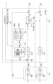
도 3은, 제어기(102)의 구성예의 하나를 나타내는 도면이다. 제어기(102)는 제어 편차 E에 기초하여 제1 신호 S1을 발생하는 제1 보상기(301)와, 계수를 조정 가능한 연산식에 따라서 제어 편차 E를 연산함으로써 보정 신호 CS를 발생하는 보정기(303)를 포함한다. 또한, 제어기(102)는 보정 신호 CS에 기초하여 뉴럴 네트워크에 의해 제2 신호 S2를 발생하는 제2 보상기(302)와, 제1 신호 S1과 제2 신호 S2에 기초하여 제어 신호 MV를 발생하는 연산기(306)를 포함한다.3 is a diagram showing one example of the configuration of the
보정기(303)는 제1 조정부(303a), 제2 조정부(303b)를 포함하는 복수의 보정기를 갖고 있고, 제어 상태에 따라 사용하는 조정부(접속되는 조정부)를 선택할 수 있다. 제어 신호 MV는, 제1 신호 S1과 제2 신호 S2의 합이며, 연산기(306)는 가산기로 구성될 수 있다. 또한, 제어 신호 MV는, 제1 신호 S1을 제2 신호 S2에 기초하여 보정한 신호이다. 제어기(102)는 목표값 R과 제어량 CV의 차분인 제어 편차 E를 발생하는 감산기(305)를 포함한다. 제어량 CV는, 제어 대상(103)이 구비하고 있는 도시하지 않은 센서 등에 의해 계측됨으로써 취득된다. 또한, 제1 신호 S1에 기초하여 제어 대상(103)을 제어한 결과인 제어량과 목표값 R의 차에 비하여, 제어 신호 MV에 기초하여 제어 대상(103)을 제어한 결과인 제어량과 목표값 R의 차의 쪽이 작다.The
제어기(102)는 동작 이력 기록부(304)를 더 포함한다. 도 2에 있어서의 학습부(201)는 도 3에 있어서의 제2 보상기(302)의 뉴럴 네트워크 파라미터값을 결정하기 위한 학습을 행하도록 구성된다. 학습부(201)에 의한 학습을 위해서, 동작 이력 기록부(304)는 학습부(201)에 의한 학습에 요하는 동작 이력을 기록하고, 기록한 동작 이력을 학습부(201)에 제공한다. 동작 이력이란, 예를 들어 제2 보상기(302)에 대한 입력 데이터인 보정 신호 CS와, 제2 보상기(302)의 출력 데이터인 제2 신호 S2이지만, 제어 편차와 제2 보상기(302)의 출력 데이터인 제2 신호 S2여도 되고, 다른 데이터여도 된다. 제1 조정부(303a), 제2 조정부(303b)는 임의의 파라미터를 초깃값으로 하여 학습을 행할 수 있다.The
이하의 실시예 1 내지 5에 있어서, 보정기(303)의 구성예를 설명한다. 실시예 1 내지 5에서는, 보정기(303)가 제어 편차 E에 기초하여 보정 신호 CS를 생성하기 위해서 사용하는 연산식의 예를 나타낸다. 연산식은, 예를 들어 단항식 또는 다항식일 수 있다.In
(실시예 1)(Example 1)
실시예 1에 있어서, 제1 조정부(303a), 제2 조정부(303b)는 이하의 식 (1)로 표시되는 제어 특성을 갖는다. 여기서, 보정기(303)에 대한 입력(E)를 x, 보정기(303)의 출력(CS)을 y, 임의의 계수(상수)를 Kp라 한다.In Example 1, the
(실시예 2)(Example 2)
실시예 2에 있어서, 제1 조정부(303a), 제2 조정부(303b)는 이하의 식 (2)로 표시되는 제어 특성을 갖는다. 여기서, 보정기(303)에 대한 입력(E)을 x, 보정기(303)의 출력(CS)을 y, 시각을 t, 임의의 계수(상수)를 Ki라 한다. 또한, 적분은 복수회 행해도 된다. 적분은 어떤 시간 구간의 정적분이어도 되고, 부정적분이어도 된다.In Example 2, the
(실시예 3)(Example 3)
실시예 3에 있어서, 제1 조정부(303a), 제2 조정부(303b)는 이하의 식 (3)으로 표시되는 제어 특성을 갖는다. 여기서, 보정기(303)에 대한 입력(E)을 x, 보정기(303)의 출력(CS)을 y, 시각을 t, 임의의 계수(상수) Kd라 한다. 또한, 미분은 복수회 행해도 된다.In Example 3, the
(실시예 4)(Example 4)
실시예 4에 있어서, 제1 조정부(303a), 제2 조정부(303b)는 이하의 식 (4)로 표시되는 제어 특성을 갖는다. 여기서, 보정기(303)에 대한 입력(E)을 x, 보정기(303)의 출력(CS)을 y, 임의의 계수(상수)를 Kp, Ki, Kd라 한다. 또한, 적분 및 미분은 복수회 행해도 된다.In Example 4, the
(실시예 5)(Example 5)
실시예 5에 있어서, 제1 조정부(303a), 제2 조정부(303b)는 이하의 식 (5)의 연산식으로 표시되는 제어 특성을 갖는다. 여기서, 보정기(303)에 대한 입력(E)을 x, 보정기(303)의 출력(CS)을 y, 다중 적분의 적분 계수를 n, 미분 계수를 m, 임의의 계수(상수)를 Kp, n중적분일 때 임의의 계수(상수)를 Ki_n, m계 미분일 때 임의의 상수를 Kd_m이라 한다.In Example 5, the
실시예 1 내지 5는, 보정기(303)가 보정 신호 CS를 생성하기 위해서 사용하는 연산식이, 제어 편차 E에 비례하는 항, 적분을 행하는 항, 및 미분을 행하는 항 중 적어도 하나를 포함하는 예로서 이해될 수 있다.
실시예 1 내지 5에서 예를 든 연산식의 계수(상수) Kp, Ki, Kd, Ki_n, Kd_m은, 보정기(303)의 조정 가능한 파라미터의 예이다. 제1 조정부(303a), 제2 조정부(303b)는 미리 상정되는 제어 상태의 변화에 따라서, 실시예 1 내지 5 중 어느 것을 사용한 최적의 파라미터를 결정해 둔다. 제어 상태란, 예를 들어 동기 제어의 전환이나 제어기의 전환, 동작 패턴의 전환, 온도나 소음, 바닥 진동 등의 환경이나 외란의 변화 등이다. 제어 상태에 따른 제1 조정부(303a), 제2 조정부(303b)를 선택함으로써, 최적의 제어 특성을 얻을 수 있다. 보정기를 복수 구성함에 따른 조정 시간은, 뉴럴 네트워크를 복수 구성함에 따른 조정 시간보다도 짧기 때문에, 시간 단축의 관점에서 유리하다.Coefficients (constants) Kp, Ki, Kd, Ki_n, and Kd_m of the arithmetic expressions given as examples in Examples 1 to 5 are examples of adjustable parameters of the
또한, 시스템 SS의 동작 중에 제어 대상(103)의 상태나 외란 환경이 변화된 경우에 있어서, 실시예 1 내지 5로서 예시된 연산식(의 계수)의 값(파라미터값)을 조정함으로써, 그 변화에 대응할 수 있다. 보정기(303)의 연산식(의 계수)의 값의 조정에 요하는 시간은, 뉴럴 네트워크의 재학습에 요하는 시간보다도 짧다. 따라서, 시스템 SS의 생산성을 떨어뜨리지 않고, 제어 정밀도를 유지할 수 있다. 즉, 보정기(303)를 도입함으로써, 제어 대상(103)의 상태 변화나 외란 환경의 변화에 대한 관용성을 향상시킬 수 있다.In addition, when the state of the
(실시예 6)(Example 6)
실시예 6 내지 8은, 제어 상태의 변화와, 보정기(303)에서 사용되는 조정부의 전환의 관계성에 대하여 설명한다.Embodiments 6 to 8 explain the relationship between the change in the control state and the switching of the adjustment unit used in the
도 4는, 실시예 6에 있어서의 제어기(102)의 구성예를 나타내는 도면이다. 실시예 6에서는, 도 4에 도시한 바와 같이, 제어 대상(103a), 제어 대상(103b)을 포함하는 복수의 제어 대상에 대하여 각각 개별로 제어를 행할지, 동기시켜 제어를 행할지를 전환할 수 있다. 실시예 6에 있어서의 제어 상태란, 복수의 제어 대상을 개별로 제어할지, 동기시켜 제어할지에 따라 정해지는 상태이며, 복수의 제어 대상을 동기 제어할지에 따라 적절한 조정부의 전환을 실행한다. 또한, 실시예 6에서는, 동기 제어 전환부(402)의 상태에 따라 보정기(303)의 전환을 행하는 구성으로 되어 있고, 제1 조정부(303a)를 사용할지, 제2 조정부(303b)를 사용할지를 선택할 수 있다. 또한, 실시예 6에서는, 제어 대상(103a)의 제어가 행해지는 축을 마스터축, 제어 대상(103b)의 제어가 행해지는 축을 슬레이브축으로 하여, 슬레이브축이 마스터축을 추종하는 마스터 슬레이브 방식이라고 불리는 동기 제어에 대하여 설명한다.4 is a diagram showing a configuration example of the
제어기(102)는 제어 대상(103)이 구비하고 있는 도시하지 않은 센서로 계측한 제어 대상(103a, 103b) 각각의 제어량 CVa, CVb를 취득하여, 각각의 목표값 Ra, Rb의 차분을 각각 제어 편차 Ea, Eb로서 계산한다.The
제어 편차 Ea는 제어기(301a)에 입력된다. 제어기(301b)와, 제어기(301b)와 병렬로 구성되어 있는 뉴럴 네트워크(302)의 전단에 마련된 보정기(303)에 대한 입력은, 제어 대상(103a)과 제어 대상(103b)을 동기 제어를 할지 여부로 전환할 수 있다. 보정기(303)로의 입력은, 제어 대상(103a)과 제어 대상(103b)의 동기 제어를 전환하는 동기 제어 전환부(402)에 의해 전환되는 제어 편차 Eb, 또는 제어 편차 Eb와 제어 편차 Ea의 차분인 동기 편차 Ec를 선택할 수 있다. 보정기(303)의 출력은, 동기 제어 전환부(402)의 상태에 따라서, 제1 조정부(303a)를 사용할지, 제2 조정부(303b)를 사용할지를 선택할 수 있다.The control deviation Ea is input to the
실시예 6의 구체예로서, 예를 들어 노광 장치에 적용하는 경우, 플레이트 스테이지와 마스크 스테이지를 동기시키고 있을 때와, 그 이외의 동작을 할 때는, 다른 조정부를 선택해도 된다. 이때, 제1 조정부(303a)와 제2 조정부(303b)는 플레이트 스테이지와 마스크 스테이지가 동기하고 있을 때와, 그 이외의 동작을 할 때에 있어서, 각각 파라미터가 최적화되어 있다. 동기 제어 전환부(402)의 상태에 따라 선택된 제1 조정부(303a), 제2 조정부(303b)의 출력은 뉴럴 네트워크(302)(제2 보상기)에 입력된다. 보상기(301a)의 출력을 제어 신호 MVa라 한다. 보상기(301b)의 출력과 뉴럴 네트워크(302)의 출력을 가산하고, 제어 신호 MVb라 한다. 제어기(102)는 제어 신호 MVa, MVb를 각각 제어 대상(103a, 103b)으로 출력한다.As a specific example of Example 6, for example, when applying to an exposure apparatus, when synchronizing a plate stage and a mask stage, and when performing other operations, you may select another adjusting unit. At this time, the parameters of the
제1 조정부(303a), 제2 조정부(303b)는 동기 제어 전환부(402)의 상태에 따라서, 실시예 1 내지 5 중 어느 것을 사용한 최적의 파라미터를 결정해 둔다. 동기 제어 전환부(402)의 상태에 따른 제1 조정부(303a), 제2 조정부(303b)를 선택함으로써, 최적의 제어 특성을 얻을 수 있다.The
보정기(303)가 복수의 조정부로부터 최적의 조정부를 선택하는 구성으로 되어 있음에 따른 조정 시간의 증가는, 뉴럴 네트워크를 복수 구성함에 따른 조정 시간의 증가보다도 짧다. 또한, 실시예 1 내지 5 중 어느 것을 사용한 운용 중에 제어 대상(103)의 상태나 외란 환경이 변화된 경우에 있어서, 실시예 1 내지 5의 파라미터를 조정함으로써 그 변화에 대응할 수 있다. 제1 조정부(303a), 제2 조정부(303b)의 조정에 요하는 시간은 뉴럴 네트워크의 재학습에 요하는 시간보다도 짧다. 실시예 6에 있어서, 제어 대상의 상태나 외란 환경에 맞는 복수의 보상을 행하는 경우에 있어서도, 연산 시간이나 학습 시간의 증가를 억제할 수 있어, 제어 대상의 상태 변화나 외란 환경에 변화가 발생하여도 적정한 제어 특성을 단시간에 조정할 수 있다.The increase in the adjustment time due to the configuration in which the
(실시예 7)(Example 7)
도 5는, 실시예 7에 있어서의 제어기(102)의 구성예를 나타내는 도면이다. 실시예 7에서는, 제어 대상(103)의 상태나 동작에 따라 보상기(301)의 전환을 행하는 구성으로 되어 있고, 보상기(301a)를 사용할지, 보상기(301b)를 사용할지를 선택할 수 있다. 실시예 7에 있어서의 제어 상태란, 복수의 보상기 중 어느 보상기를 사용할지에 따라 정해지는 상태이며, 보상기(301a)를 사용할지, 보상기(301b)를 사용할지에 따라 조정부의 전환을 실행한다. 또한, 실시예 7에서는, 보상기(301)의 상태에 따라 보정기(303)의 전환을 행하는 구성으로 되어 있고, 제1 조정부(303a)를 사용할지, 제2 조정부(303b)를 사용할지를 선택할 수 있다.5 is a diagram showing a configuration example of the
실시예 7의 구체예로서, 예를 들어 노광 장치에 적용하는 경우, 플레이트 스테이지의 노광 동작 시에는 보상기(301a)를 플레이트 반송 동작에 있어서는 보상기(301b)를 사용한다고 한 게인의 전환이 발생할 때에 적용해도 된다. 즉, 제어 대상(103)의 게인 전환이 발생하고 있는지 여부에 기초하여 복수의 조정부로부터 제어 편차 E의 보정에 사용하는 조정부가 선택되면 된다. 이때, 제1 조정부(303a)와 제2 조정부(303b)는 보상기(301a), 보상기(301b)에 대하여 실시예 1 내지 5 중 어느 것을 사용한 최적의 파라미터를 결정해 둔다. 보상기(301)의 상태에 따른 제1 조정부(303a), 제2 조정부(303b)를 선택함으로써, 최적의 제어 특성을 얻을 수 있다.As a specific example of Example 7, when applied to an exposure apparatus, for example, when a change in gain occurs by using the
보정기(303)가 복수의 조정부로부터 최적의 조정부를 선택하는 구성으로 되어 있음에 따른 조정 시간의 증가는, 뉴럴 네트워크를 복수 구성함에 따른 조정 시간의 증가보다도 짧다. 또한, 실시예 1 내지 5 중 어느 것을 사용한 운용 중에 제어 대상(103)의 상태나 외란 환경이 변화된 경우에 있어서, 실시예 1 내지 5의 파라미터를 조정함으로써 그 변화에 대응할 수 있다. 제1 조정부(303a), 제2 조정부(303b)의 조정에 요하는 시간은 뉴럴 네트워크의 재학습에 요하는 시간보다도 짧다. 실시예 7에 있어서, 제어 대상의 상태나 외란 환경에 맞는 복수의 보상을 행하는 경우에 있어서도, 연산 시간이나 학습 시간의 증가를 억제할 수 있어, 제어 대상의 상태 변화나 외란 환경에 변화가 발생해도, 적정한 제어 특성을 단시간에 조정할 수 있다.The increase in the adjustment time due to the configuration in which the
(실시예 8)(Example 8)
도 6은, 실시예 8에 있어서의 제어기(102)의 구성예를 나타내는 도면이다. 실시예 8에 있어서의 제어 상태란, 제어 대상의 동작 패턴(403)이 변화하고 있는지 여부에 의해 정해지는 상태이다. 동작 패턴(403)의 구체예에 대해서는, 후술한다. 실시예 8에서는, 동작 패턴(403)의 상태에 따라 조정부의 전환을 행하는 구성으로 되어 있고, 제1 조정부(303a)를 사용할지, 제2 조정부(303b)를 사용할지를 선택할 수 있다.6 is a diagram showing a configuration example of the
실시예 7의 구체예로서, 예를 들어 노광 장치 등에 사용되는 스테이지 장치에 적용하는 경우, 스테이지의 구동 시의 가속 구간과, 그 이외의 동작 패턴으로 전환해서 적용해도 된다. 이때, 제1 조정부(303a)와 제2 조정부(303b)는 제어 대상(103)의 동작 패턴(403)의 상태에 따라서, 실시예 1 내지 5 중 어느 것을 사용한 최적의 파라미터를 결정해 둔다. 동작 패턴(403)의 상태에 따른 제1 조정부(303a), 제2 조정부(303b)를 선택함으로써, 최적의 제어 특성을 얻을 수 있다.As a specific example of Example 7, for example, when applying to a stage apparatus used for an exposure apparatus or the like, it may be applied by switching between an acceleration section during driving of the stage and an operation pattern other than that. At this time, the
보정기(303)가 복수의 조정부로부터 최적의 조정부를 선택하는 구성으로 되어 있음에 따른 조정 시간의 증가는, 뉴럴 네트워크를 복수 구성함에 따른 조정 시간의 증가보다도 짧다. 또한, 실시예 1 내지 5 중 어느 것을 사용한 운용 중에 제어 대상(103)의 상태나 외란 환경이 변화된 경우에 있어서, 실시예 1 내지 5의 파라미터를 조정함으로써 그 변화에 대응할 수 있다. 제1 조정부(303a), 제2 조정부(303b)의 조정에 요하는 시간은 뉴럴 네트워크의 재학습에 요하는 시간보다도 짧다. 실시예 8에 있어서, 제어 대상의 상태나 외란 환경에 맞는 복수의 보상을 행하는 경우에 있어서도, 연산 시간이나 학습 시간의 증가를 억제할 수 있어, 제어 대상의 상태 변화나 외란 환경에 변화가 발생하여도 적정한 제어 특성을 단시간에 조정할 수 있다.The increase in the adjustment time due to the configuration in which the
도 7에 예시되는 바와 같이, 제어 장치(100)는 제1 조정부(303a)를 사용할지, 제2 조정부를 사용할지를 선택하는 설정부(202)를 구비해도 된다. 또한, 설정부(202)는 보정기(303)의 파라미터값을 설정하는 역할을 갖고 있어도 된다.As illustrated in FIG. 7 , the control device 100 may include a setting unit 202 that selects whether to use the
설정부(202)는 조정부의 전환이나 파라미터값을 조정하기 위한 조정 처리를 실행하고, 이 조정 처리에 의해 조정부의 전환이나 파라미터값을 결정하여 설정해도 되고, 유저로부터의 지령에 기초하여 조정부의 전환이나 파라미터값을 설정해도 된다. 전자에 있어서는, 설정부(202)는 제어기(102)의 동작을 확인하기 위한 확인 시퀀스를 시퀀스부(101)로 보내고, 이 확인 시퀀스에 기초하여 시퀀스부(101)에 목표값 R을 생성시킬 수 있다. 그리고, 설정부(202)는 그 목표값 R에 기초하여 동작하는 제어기(102)로부터 동작 이력(예를 들어, 제어 편차)을 취득하고, 그 동작 이력에 기초하여 보정기(303)의 전환의 필요성의 유무나 파라미터값을 결정할 수 있다. 이러한 기능을 갖는 설정부(202)는 보정기(303)의 전환이나 파라미터값을 조정하는 조정부로서 이해할 수 있다.The setting unit 202 may perform switching of the adjustment unit or adjustment processing for adjusting parameter values, and may determine and set the switching of the adjustment unit or parameter values by this adjustment processing, or switch the adjustment unit based on a command from the user. or parameter values can be set. In the former, the setting unit 202 may send a confirmation sequence for confirming the operation of the
설정부(202)는 시퀀스부(101)가 생산 시퀀스에 기초하여 목표값 R을 생성하는 생산 시에, 제어기(102)로부터 동작 이력(예를 들어, 제어 편차)을 취득하고, 그 동작 이력에 기초하여 보정기(303)의 파라미터값의 조정을 실행할지 여부를 결정하여도 된다. 또는, 시퀀스부(101)가 생산 시퀀스에 기초하여 목표값 R을 생성하는 생산 시에 있어서 설정부(202)에 의한 보정기(303)의 파라미터값의 조정을 실행할지 여부를 판단하는 판단부가 설정부(202)와는 별도로 마련되어도 된다.The setting unit 202 acquires an operation history (e.g., control deviation) from the
다음으로 본 실시 형태에 있어서의 시스템에 의해 생산이 행해지는 예에 대하여 설명한다. 도 8은, 본 실시 형태의 시스템 SS를 생산 장치에 적용한 경우의 시스템 SS의 동작예이다.Next, an example in which production is performed by the system in the present embodiment will be described. 8 is an example of operation of the system SS when the system SS of the present embodiment is applied to production equipment.
공정 S501에서는, 시퀀스부(101)가 주어진 생산 시퀀스에 기초하여 목표값 R을 생성하고, 제어 장치(100) 또는 제어기(102)에 제공한다. 제어 장치(100) 또는 제어기(102)는 그 목표값 R에 기초하여 제어 대상(103)을 제어한다.In step S501, the sequence unit 101 generates a target value R based on the given production sequence, and provides it to the control device 100 or
공정 S502에서는, 설정부(202)는 공정 S501에 있어서의 제어기(102)의 동작 이력(예를 들어, 제어 편차)을 취득한다.In step S502, the setting unit 202 acquires the operation history (eg, control deviation) of the
공정 S503에서는, 설정부(202)가 공정 S502에서 취득한 동작 이력에 기초하여, 조정부의 전환이나, 파라미터값의 조정(또는 재조정) 등의 보정기(303)의 조정을 실행할지 여부를 판단할 수 있다. 설정부(202)는, 예를 들어 동작 이력이 소정 조건을 충족하는 경우에, 조정부의 전환 파라미터값의 조정(또는 재조정)을 실행한다고 판단할 수 있다. 소정 조건이란, 생산을 정지시켜야 할 조건이며, 예를 들어 동작 이력으로서 취득한 제어 편차가 규정값을 초과한 경우에 보정기(303)의 조정이 필요하다고 판단된다. 그리고, 설정부(202)에 의한 보정기(303)의 조정을 실행하는 경우에는 공정 S504로 진행하고, 그렇지 않은 경우에는 공정 S505로 진행한다.In step S503, the setting unit 202 can determine whether to perform adjustment of the
공정 S504에서는, 설정부(202)는 보정기(303)의 조정을 실행한다. 이 조정은, 제2 보상기(302)의 파라미터값이 종전의 상태로 유지된 상태에서 이루어지고, 이 조정에 의해, 예를 들어 보정기(303)의 파라미터값(계수)이 재설정된다.In step S504, the setting unit 202 adjusts the
공정 S505에서는, 시퀀스부(101)는 생산 시퀀스에 따르는 생산을 종료할지 여부를 판단하고, 종료하지 않는 경우에는 공정 S501로 되돌아가고, 종료하는 경우에는 생산을 종료한다. 이상의 처리에 의하면, 생산을 정지시켜야 할 상태로 된 경우에 있어서도, 빠르게 보정기(303)의 파라미터값을 조정하고, 생산의 중단을 최소한으로 억제하면서 생산을 재개시킬 수 있다.In step S505, the sequence unit 101 judges whether to end production according to the production sequence, returns to step S501 if not, and ends production in the case of ending. According to the above processing, even when production is in a state where it is necessary to stop, it is possible to quickly adjust the parameter value of the
공정 S504에서는, 설정부(202)는 확인 시퀀스를 시퀀스부(101)로 보내고, 시퀀스부(101)에 확인 시퀀스를 실행시켜 확인 시퀀스에 있어서의 동작 이력(예를 들어, 제어 편차)을 제어기(102)로부터 취득할 수 있다. 그리고, 설정부(202)는 그 동작 이력의 주파수 해석을 행하고, 그 결과에 기초하여, 개선해야 할 주파수를 결정하고, 그 주파수에 있어서의 제어 편차가 규정값 이내가 되도록 보정기(303)의 파라미터값을 결정할 수 있다. 공정 S504의 더욱 구체적인 예에 대해서는, 제2 실시 형태에 있어서 설명한다.In step S504, the setting unit 202 sends the confirmation sequence to the sequence unit 101, and causes the sequence unit 101 to execute the confirmation sequence, and the operation history (e.g., control deviation) in the confirmation sequence is stored in the controller ( 102) can be obtained from Then, the setting unit 202 performs frequency analysis of the operation history, determines a frequency to be improved based on the result, and adjusts the parameters of the
도 9에는, 외란 억압 특성의 계측 결과를 예시하고 있는 도면이다. 도 2에 있어서의 제어 신호 MV로서 사인파를 입력했을 때의 제어 편차를 출력으로 했을 때의 주파수 응답을 계측한 결과임을 외란 억압 특성이라고 칭한다. 도 9에 있어서, 횡축은 주파수, 종축은 외란 억압 특성의 게인을 나타낸다. 외란 억압 특성은, 제어 신호 MV에 외란이 가산된 경우의 제어 편차 E의 주파수 응답을 나타내기 때문에, 게인이 큰 것은, 외란을 억압하는 효과가 낮음을 나타낸다. 한편, 게인이 작은 것은, 외란을 억압하는 효과가 높음을 나타낸다. 도 9에 있어서, 파선은, 조정 전의 외란 억압 특성을 나타내고 있으며, 실선은 조정 후의 외란 억압 특성을 나타내고 있다.9 is a diagram illustrating measurement results of disturbance suppression characteristics. The result of measuring the frequency response when the control deviation when a sine wave is input as the control signal MV in FIG. 2 is output is referred to as a disturbance suppression characteristic. In Fig. 9, the horizontal axis represents the frequency, and the vertical axis represents the gain of the disturbance suppression characteristic. Since the disturbance suppression characteristic shows the frequency response of the control deviation E when a disturbance is added to the control signal MV, a large gain indicates a low disturbance suppression effect. On the other hand, when the gain is small, the effect of suppressing disturbance is high. In Fig. 9, the broken line represents the disturbance suppression characteristic before adjustment, and the solid line represents the disturbance suppression characteristic after adjustment.
도 9에 있어서의 일점쇄선으로 나타낸 주파수를, 외란 억압 특성을 개선해야 할 주파수로서 정해서 공정 S504를 실행하면, 예를 들어 실선으로 나타내어지는 외란 억압 특성을 얻을 수 있다. 개선해야 할 주파수에 있어서 외란 억압 특성의 게인이 작아져서, 외란 억압 특성이 향상되어 있음을 알 수 있다. 실시예 1 내지 8에서, 뉴럴 네트워크의 전단에 마련한 보정기(303)의 파라미터 조정을 행하는 경우, 도 9에 도시한 외란 억압 특성을 지표로 파라미터 조정을 행해도 된다.If the frequency indicated by the dashed-dotted line in Fig. 9 is determined as the frequency at which the disturbance suppression characteristic should be improved and step S504 is executed, the disturbance suppression characteristic indicated by the solid line can be obtained, for example. It can be seen that the gain of the disturbance suppression characteristic is reduced at the frequency to be improved, and the disturbance suppression characteristic is improved. In
<제2 실시 형태><Second Embodiment>
본 실시 형태에서는, 제1 실시 형태에서 설명한 제어 시스템 SS를 스테이지 제어 장치(800)에 적용하는 예에 대하여 설명한다. 본 실시 형태로서 언급하지 않은 사항은, 제1 실시 형태에 따른다. 도 10은, 도 1에서 도시한 제어 시스템 SS를 스테이지 제어 장치(800)에 적용했을 때의 하드웨어 구성을 나타내는 도면이다.In this embodiment, an example in which the control system SS described in the first embodiment is applied to the
스테이지 제어 장치(800)는 기판 등의 물체의 위치를 제어하기 위하여, 상기 물체를 스테이지(804) 위에 보유 지지한 상태에서 스테이지(804)를 제어하도록 구성되어 있다. 스테이지 제어 장치(800)는 제어 기판(801), 전류 드라이버(802), 모터(803), 스테이지(804) 및 센서(805)를 구비한다. 제어 기판(801)은 제1 실시 형태의 시스템 SS에 있어서의 제어 장치(100) 또는 제어기(102)에 대응한다. 전류 드라이버(802), 모터(803), 스테이지(804) 및 센서(805)는 제1 실시 형태의 시스템 SS에 있어서의 제어 대상(103)에 대응한다. 단, 전류 드라이버(802)는 제어 기판(801)에 포함되어도 된다. 도 10에는 도시되어 있지 않지만, 스테이지 제어 장치(800)는 시퀀스부(101), 학습부(201), 설정부(202)를 구비할 수 있다.The
제어 기판(801)에는, 시퀀스부(101)로부터 목표값으로서의 위치 목표값이 공급될 수 있다. 제어 기판(801)은 시퀀스부(101)로부터 공급되는 위치 목표값과 센서(805)로부터 공급되는 위치 정보에 기초하여, 제어 신호로서의 전류 지령을 발생하고, 전류 드라이버(802)에 공급할 수 있다. 또한, 제어 기판(801)은 동작 이력을 시퀀스부(101)에 공급할 수 있다.A position target value as a target value may be supplied to the
전류 드라이버(802)는 전류 지령에 따른 전류를 모터(803)에 공급할 수 있다. 모터(803)는 전류 드라이버(802)로부터 공급되는 전류를 추력으로 변환하고, 그 추력으로 스테이지(804)를 구동하는 액추에이터일 수 있다. 스테이지(804)는, 예를 들어 플레이트 또는 마스크 등의 물체를 보유 지지할 수 있다. 센서(805)는 스테이지(804)의 위치를 검출하고, 그것에 의해 얻어진 위치 정보를 제어 기판(801)에 공급할 수 있다.The current driver 802 may supply current according to a current command to the motor 803 . The motor 803 may be an actuator that converts current supplied from the current driver 802 into thrust and drives the stage 804 with the thrust. The stage 804 can hold an object such as a plate or a mask, for example. The sensor 805 can detect the position of the stage 804 and supply positional information obtained thereby to the
도 11에는, 제어 기판(801)의 구성예가 블록선도로서 도시되어 있다. 제어 기판(801)은 제어 대상으로서의 스테이지(804)의 위치 제어 편차 E에 기초하여 제1 신호 S1을 발생하는 제1 보상기(301)와, 계수를 조정 가능한 연산식에 따라서 제어 편차 E를 보정함으로써 보정 신호 CS를 발생하는 보정기(303)를 포함할 수 있다. 또한, 제어 기판(801)은 보정 신호 CS에 기초하여 뉴럴 네트워크에 의해 제2 신호 S2를 발생하는 제2 보상기(302)와, 제1 신호 S1과 제2 신호 S2에 기초하여 제어 신호로서 전류 지령을 발생하는 연산기(306)를 포함할 수 있다. 또한, 제어 기판(801)은 위치 목표값 PR과 위치 정보의 차분인 제어 편차 E를 발생하는 감산기(305)를 포함할 수 있다.11, an example of the configuration of the
제2 실시 형태의 스테이지 제어 장치(100)에 있어서도, 도 7에서 설명한 제1 실시 형태와 마찬가지로, 학습부(201)를 구비하고 있어도 된다. 학습부(201)는 제2 보상기(302)의 뉴럴 네트워크 파라미터값을 결정하기 위한 학습을 행하도록 구성될 수 있다. 학습부(201)에 의한 학습을 위해서, 동작 이력 기록부(304)는 학습부(201)에 의한 학습에 요하는 동작 이력을 기록하고, 기록한 동작 이력을 학습부(201)에 제공할 수 있다. 동작 이력은, 예를 들어 제2 보상기(302)에 대한 입력 데이터인 보정 신호 CS와, 제2 보상기(302)의 출력 데이터인 제2 신호 S2일 수 있지만, 다른 데이터여도 된다.The stage control device 100 of the second embodiment may also include a learning unit 201 as in the first embodiment described with reference to FIG. 7 . The learning unit 201 may be configured to perform learning to determine the neural network parameter value of the
제2 실시 형태의 스테이지 제어 장치(100)는 설정부(202)를 구비할 수 있다. 설정부(202)는 보정기(303)의 파라미터값을 조정하기 위한 조정 처리를 실행하고, 이 조정 처리에 의해 보정기(303)의 파라미터값을 결정하여 설정해도 되고, 유저로부터의 지령에 기초하여 보정기(303)의 파라미터값을 설정해도 된다.The stage control device 100 of the second embodiment may include a setting unit 202 . The setting unit 202 may execute an adjustment process for adjusting the parameter values of the
도 8을 원용하여, 제2 실시 형태의 스테이지 제어 장치(800)를 생산 장치에 적용한 경우의 스테이지 장치(800)의 동작을 예시적으로 설명한다. 공정 S501에서는, 시퀀스부(101)가 주어진 생산 시퀀스에 기초하여 위치 목표값 PR을 생성하고, 스테이지 제어 장치(800)에 제공할 수 있다. 스테이지 제어 장치(800)는 그 위치 목표값 PR에 기초하여 스테이지(804)의 위치를 제어한다.Referring to FIG. 8 , the operation of the
공정 S502에서는, 설정부(202)가 공정 S501에 있어서의 제어 기판(801)의 동작 이력(예를 들어, 제어 편차)을 취득한다.In step S502, the setting unit 202 acquires the operation history (eg, control deviation) of the
공정 S503에서는, 설정부(202)가 공정 S502에서 취득한 동작 이력에 기초하여, 조정부의 전환이나, 파라미터값의 조정(또는 재조정) 등의 보정기(303)의 조정을 실행할지 여부를 판단할 수 있다. 설정부(202)는, 예를 들어 동작 이력이 소정 조건을 충족하는 경우에, 보정기(303)의 조정을 실행한다고 판단할 수 있다. 소정 조건이란, 생산을 정지시켜야 할 조건이며, 예를 들어 스테이지(804)의 등속 구동 중의 위치 제어 편차의 최댓값이 미리 결정된 규정값을 초과한 경우에 보정기(303)의 조정이 필요하다고 판단된다. 그리고, 설정부(202)에 의한 보정기(303)의 조정을 실행하는 경우에는 공정 S504로 진행하고, 그렇지 않은 경우에는 공정 S505로 진행한다.In step S503, the setting unit 202 can determine whether to perform adjustment of the
공정(504)에서는, 설정부(202)는 보정기(303)의 조정을 실행할 수 있다. 공정 S505에서는, 시퀀스부(101)는 생산 시퀀스에 따르는 생산을 종료할지 여부를 판단하고, 종료하지 않은 경우에는 공정 S501로 되돌아가고, 종료한 경우에는 생산을 종료한다.In step 504, the setting unit 202 can adjust the
도 12에는, 공정 S504에 있어서의 보정기(303)의 조정 중, 파라미터값의 조정(또는 파라미터값의 재조정)에 있어서의 처리의 구체예가 도시되어 있다. 공정 S601에서는, 설정부(202)는 스테이지 제어 장치(800)의 동작을 확인하기 위한 확인 시퀀스를 시퀀스부(101)로 보내고, 이 확인 시퀀스에 기초하여 시퀀스부(101)에 위치 목표값 PR을 생성시킬 수 있다. 공정 S602에서는, 설정부(202)는 그 위치 목표값 PR에 기초하여 동작하는 제어기(102)로부터 동작 이력으로서의 위치 제어 편차 E를 취득할 수 있다.Fig. 12 shows a specific example of processing in adjusting parameter values (or re-adjusting parameter values) during the adjustment of the
여기서, 도 13을 참조하여, 파라미터 조정 전과 후의 위치 제어 편차 E의 변화에 대하여 설명한다. 도 13은, 파라미터 조정의 전후에 있어서의 위치 제어 편차를 예시하는 도면이다. 도 13에 있어서, 횡축은 시간, 종축은 위치 제어 편차 E를 나타내고 있다. 여기서, 점선으로 나타내어지는 곡선은, 보정기(303)의 파라미터값을 조정하기 전의 위치 제어 편차 E이며, 위치 제어 정밀도가 악화되어 있음을 나타내고 있다. 파라미터값을 조정함으로써, 위치 제어 편차 E의 변동을 작게 할 수 있다.Here, with reference to Fig. 13, the change in position control deviation E before and after parameter adjustment will be described. 13 is a diagram illustrating position control deviations before and after parameter adjustment. In Fig. 13, the horizontal axis represents time, and the vertical axis represents position control deviation E. Here, the curve indicated by the dotted line is the position control deviation E before adjusting the parameter values of the
공정 S603에서는, 설정부(202)는 공정 S602에서 취득한 위치 제어 편차 E의 주파수 해석을 행할 수 있다. 여기서, 도 14를 참조하여, 파라미터 조정 전과 후에 있어서의 주파수 해석의 결과에 대하여 설명한다. 도 14는, 파라미터 조정의 전후에 있어서의 주파수 해석의 결과를 예시하는 도면이다. 도 14에 있어서, 횡축은 주파수, 종축은 파워 스펙트럼이다. 점선은, 조정 전에 있어서 최대 스펙트럼을 나타내는 주파수를 나타내고 있다. 공정 S604에서는, 설정부(202)는, 예를 들어 파워 스펙트럼에 있어서 최대 스펙트럼을 나타내는 주파수를, 개선해야 할 주파수로서 결정할 수 있다.In step S603, the setting unit 202 can perform frequency analysis of the position control deviation E obtained in step S602. Here, with reference to FIG. 14, the result of the frequency analysis before and after parameter adjustment is demonstrated. 14 is a diagram illustrating results of frequency analysis before and after parameter adjustment. In Fig. 14, the horizontal axis is the frequency, and the vertical axis is the power spectrum. The dotted line represents the frequency showing the maximum spectrum before adjustment. In step S604, the setting unit 202 can determine, for example, a frequency that exhibits the maximum spectrum in the power spectrum as the frequency to be improved.
공정 S605 내지 S610은, 보정기(303)의 파라미터값을 조정하는 조정 처리의 구체예이다. 여기에서는, 파라미터값의 조정 방법으로서 최급 강하법을 채용하여 예를 설명하지만, 다른 방법이 이용되어도 된다. 공정 S605에서는, 설정부(202)는 n을 1로 초기화한다. 예를 들어, 보정기(303)의 연산식이 1차 적분항, 비례항 및 1차 미분항의 3항으로 구성되는 경우, 파라미터값을 조정해야 할 파라미터는, Ki, Kp, Kd의 3개이다. n회째의 조정에 있어서의 파라미터값 pn을 이하의 식 (6)으로 나타낸다.Steps S605 to S610 are specific examples of adjustment processing for adjusting the parameter values of the
공정 S606에서는, 설정부(202)는 파라미터값 pn의 1회째의 조정에 있어서의 파라미터값 p1에 대해서는, 임의의 초깃값을 설정할 수 있다. n회째의 조정에서는, 후술하는 식 (8)로 나타내어지는 파라미터값 pn을 설정할 수 있다.In step S606, the setting unit 202 can set an arbitrary initial value for the parameter value p1 in the first adjustment of the parameter value pn. In the nth adjustment, the parameter value pn represented by Formula (8) mentioned later can be set.
파라미터값 pn을 조정하기 위한 목적 함수 J(pn)은, 예를 들어 공정 S604에서 결정한 주파수에 있어서의 외란 억압 특성의 게인으로 될 수 있다. 공정 S607에서는, 설정부(202)는 목적 함수 J(pn)의 구배 벡터 grad J(pn)을 측정할 수 있다. 구배 벡터 grad J(pn)은 이하의 식 (7)로 부여될 수 있다. 구배 벡터 grad J(pn)은 파라미터값 pn을 구성하는 각 요소 Ki-n, Kp-n, Kd-n을 미소량만큼 변화시킴으로써 계측될 수 있다.The objective function J(pn) for adjusting the parameter value pn can be, for example, the gain of the disturbance suppression characteristic at the frequency determined in step S604. In step S607, the setting unit 202 can measure the gradient vector grad J(pn) of the objective function J(pn). The gradient vector grad J(pn) can be given by the following equation (7). The gradient vector grad J(pn) can be measured by changing each element Ki-n, Kp-n and Kd-n constituting the parameter value pn by a small amount.
공정 S608에서는, 설정부(202)는 최급 강하법의 수렴 판정으로서, 구배 벡터 grad J(pn)의 각 요소의 값이 규정값 이하인지 여부를 판단할 수 있다. 구배 벡터 grad J(pn)의 각 요소의 값이 규정값 이하이면 설정부(202)는 보정기(303)의 파라미터값의 조정을 종료할 수 있다. 한편, 구배 벡터 grad J(pn)의 각 요소의 값이 규정값을 초과하고 있으면, 공정 S609에 있어서, 설정부(202)는 파라미터값 pn+1을 계산할 수 있다. 여기서, 파라미터값 pn+1은, 예를 들어 0보다 큰 임의의 상수 α를 사용하여, 이하의 식 (8)에 따라서 계산될 수 있다. 공정 S610에서는, 설정부(202)는 n의 값에 1을 가산하고, 공정 S606으로 되돌아간다.In step S608, the setting unit 202 can determine whether or not the value of each element of the gradient vector grad J(pn) is equal to or less than a specified value as a convergence determination of the steepest descent method. When the value of each element of the gradient vector grad J(pn) is less than or equal to the specified value, the setting unit 202 may terminate the adjustment of the parameter value of the
공정 S611에서는, 설정부(202)는 스테이지 제어 장치(800)의 동작을 확인하기 위한 확인 시퀀스를 시퀀스부(101)로 보내고, 이 확인 시퀀스에 기초하여 시퀀스부(101)에 위치 목표값 PR을 생성시킬 수 있다. 공정 S612에서는, 설정부(202)는 그 위치 목표값 PR에 기초하여 동작하는 제어기(102)로부터 동작 이력으로서의 위치 제어 편차 E를 취득할 수 있다.In step S611, the setting unit 202 sends a confirmation sequence for confirming the operation of the
공정 S613에서는, 설정부(202)는 공정 S612에서 취득한 위치 제어 편차 E가 규정값 이하인지 여부를 판단하여, 위치 제어 편차 E가 규정값을 초과하고 있으면 공정 S601로 되돌아가서 조정을 재실행하고, 위치 제어 편차 E가 규정값 이하이면 조정을 종료할 수 있다.In step S613, the setting unit 202 judges whether or not the position control deviation E obtained in step S612 is equal to or less than the prescribed value, and if the position control deviation E exceeds the prescribed value, the setting unit 202 returns to step S601 to re-execute the adjustment. If the control deviation E is less than the specified value, the adjustment can be terminated.
본 실시 형태에 따르면, 스테이지(804)를 포함하는 제어 대상의 상태나 외란이 변화된 경우에 있어서, 보정기(303)의 파라미터값을 조정함으로써, 그 변화에 대응할 수 있다. 예를 들어, 도 13의 예에서는, 점선으로 나타낸 위치 제어 편차는, 실선으로 나타낸 위치 제어 편차까지 저감되어, 제어 정밀도가 향상된다.According to the present embodiment, when the state or disturbance of the control target including the stage 804 changes, it is possible to respond to the change by adjusting the parameter value of the
식 (6)의 예에서는, 보정기(303)의 파라미터 수는 불과 3개이며, 일반적인 뉴럴 네트워크의 파라미터 수보다도 훨씬 적다. 예를 들어, 딥 뉴럴 네트워크를 사용하는 경우, 입력층의 차원 수를 5, 은닉층의 차원 수를 32의 2단, 출력층의 차원 수를 8로 하면, 파라미터 수는 1545개가 된다. 이들 1545개의 파라미터의 값을 재학습에 의해 결정하는 것보다도, 보정기(303)의 파라미터값을 조정하는 쪽이 단시간에 조정을 종료할 수 있다. 따라서, 스테이지 제어 장치(800)의 생산성을 떨어뜨리지 않고, 제어 정밀도를 유지할 수 있다.In the example of Equation (6), the number of parameters of the
<제3 실시 형태><Third Embodiment>
본 실시 형태에서는, 제1 실시 형태에서 설명한 제어 시스템 SS를 노광 장치 EXP에 적용하는 예에 대하여 설명한다. 본 실시 형태로서 언급하지 않은 사항은, 제1 실시 형태에 따른다. 도 15에는, 본 실시 형태의 노광 장치 EXP의 구성예가 모식적으로 도시되어 있다. 노광 장치 EXP는, 주사 노광 장치로서 구성될 수 있다.In this embodiment, an example in which the control system SS described in the first embodiment is applied to the exposure apparatus EXP will be described. Matters not mentioned in the present embodiment follow the first embodiment. 15 schematically shows an example of the configuration of the exposure apparatus EXP of the present embodiment. The exposure device EXP can be configured as a scanning exposure device.
노광 장치 EXP는, 예를 들어 조명 광원(1000), 조명 광학계(1001), 마스크 스테이지(1003), 투영 광학계(1004), 플레이트 스테이지(1006)를 구비할 수 있다. 조명 광원(1000)은, 수은 램프, 엑시머 레이저 광원 또는 EUV 광원을 포함할 수 있지만, 이들로 한정되지는 않는다. 조명 광원(1000)으로부터의 노광광(1010)은, 조명 광학계(1001)에 의해 균일한 조도로 투영 광학계(1004)의 조사 영역의 형태로 성형된다. 일례에 있어서, 노광광(1010)은, Y축 및 Z축에 의한 평면에 수직인 축인 X방향으로 긴 직사각형으로 성형될 수 있다. 투영 광학계(1004)의 종류에 따라서, 노광광(1010)은, 원호 형상으로 성형될 수 있다. 성형된 노광광(1010)은 마스크(원판)(1002)의 패턴에 조사되고, 마스크(1002)의 패턴을 통과한 노광광(1010)은, 투영 광학계(1004)를 통해 플레이트(1005)(기판)의 면에 마스크(1002)의 패턴의 상(像)을 형성한다.The exposure apparatus EXP may include, for example, an
마스크(1002)는 마스크 스테이지(1003)에 의해 진공 흡인 등에 의해 보유 지지되고, 플레이트(1005)는 플레이트 스테이지(1006)의 척(1007)에 의해 진공 흡인 등에 의해 보유 지지된다. 마스크 스테이지(1003) 및 플레이트 스테이지(1006)의 위치는, 레이저 간섭계 또는 레이저 스케일 등의 위치 센서(1030)와, 리니어 모터 등의 구동계(1031)와, 제어기(1032)를 구비한 다축 위치 제어 장치에 의해 제어될 수 있다. 위치 센서(1030)로부터 출력되는 위치 계측값은, 제어기(1032)에 제공될 수 있다. 제어기(1032)는, 위치 목표값과 위치 계측값의 차분인 위치 제어 편차에 기초하여 제어 신호를 발생하고, 그것을 구동계(1031)에 제공함으로써, 마스크 스테이지(1003) 및 플레이트 스테이지(1006)를 구동한다. 마스크 스테이지(1003)와 플레이트 스테이지(1006)를 Y방향으로 동기 구동하면서 플레이트(1005)를 주사 노광 함으로써 마스크(1002)의 패턴이 플레이트(1005)(위의 감광재)에 전사된다.The
제2 실시 형태를 플레이트 스테이지(1006)의 제어에 적용하는 경우에 대하여 설명한다. 도 11에 있어서의 제어 기판(801)은 제어기(1032), 전류 드라이버(802)와 모터(803)는 구동계(1031), 스테이지(804)는 플레이트 스테이지(1006), 센서(805)는 위치 센서(1030)에 해당한다. 뉴럴 네트워크를 갖는 제어기를 플레이트 스테이지(1006)의 제어에 적용함으로써, 플레이트 스테이지(1006)의 위치 제어 편차를 저감시킬 수 있다. 이에 의해, 중첩 정밀도 등을 향상시킬 수 있다. 뉴럴 네트워크의 파라미터값은, 미리 결정된 학습 시퀀스에 의해 결정될 수 있다. 그러나, 학습 시로부터의 제어 대상의 상태 변화나 외란 환경이 변화될 때에, 플레이트 스테이지(1006)의 제어 정밀도가 저하된다. 그와 같은 경우에도, 보정기의 파라미터값을 조정함으로써, 뉴럴 네트워크의 재학습을 행하는 것보다도, 단시간에 조정을 종료할 수 있다. 결과적으로, 노광 장치의 생산성을 떨어뜨리지 않고, 제어 정밀도를 유지할 수 있다.A case where the second embodiment is applied to the control of the
제2 실시 형태를 마스크 스테이지(1003)의 제어에 적용하는 경우에 대하여 설명한다. 도 11에 있어서의 제어 기판(801)은 제어기(1032), 전류 드라이버(802)와 모터(803)는 구동계(1031), 스테이지(804)는 마스크 스테이지(1003), 센서(805)는 위치 센서(1030)에 해당한다.A case where the second embodiment is applied to the control of the
제2 실시 형태를 마스크 스테이지(1003)의 제어에 적용한 경우에 있어서도, 마스크 스테이지(1003)의 위치 제어 편차를 저감시킬 수 있다. 이에 의해, 중첩 정밀도 등을 향상시킬 수 있다. 뉴럴 네트워크의 파라미터값은, 미리 결정된 학습 시퀀스에 의해 결정될 수 있다. 그러나, 학습시부터의 제어 대상의 상태 변화나 외란 환경이 변화될 때에, 마스크 스테이지(1003)의 제어 정밀도가 저하된다. 그와 같은 경우에도, 보정기의 파라미터값을 조정함으로써, 뉴럴 네트워크의 재학습을 행하는 것보다도 단시간에 조정을 종료할 수 있다. 결과적으로, 노광 장치의 생산성을 떨어뜨리지 않고, 제어 정밀도를 유지할 수 있다.Even when the second embodiment is applied to the control of the
제2 실시 형태는, 노광 장치에 있어서의 스테이지의 제어뿐만 아니라, 임프린트 장치 및 전자선 묘화 장치와 같은 다른 리소그래피 장치에 있어서의 스테이지의 제어에도 적용될 수 있다. 또한, 제1 실시 형태 또는 제2 실시 형태는, 예를 들어 물품을 반송하는 반송 기구에 있어서의 가동부, 예를 들어 물품을 보유 지지하는 핸드의 제어에도 적용될 수 있다.The second embodiment can be applied not only to stage control in an exposure apparatus, but also to stage control in other lithography apparatuses such as an imprint apparatus and an electron beam drawing apparatus. Further, the first embodiment or the second embodiment can also be applied to control of a movable part in a conveyance mechanism that conveys an article, for example, a hand that holds an article.
<물품의 제조 방법의 실시 형태><Embodiment of the manufacturing method of an article>
본 발명의 실시 형태에 따른 물품의 제조 방법은, 예를 들어 플랫 패널 디스플레이(FPD)를 제조하기에 적합하다. 본 실시 형태의 물품 제조 방법은, 기판 위에 도포된 감광제에 상기 노광 장치를 사용하여 잠상 패턴을 형성하는 공정(기판을 노광하는 공정)과, 이러한 공정에서 잠상 패턴이 형성된 기판을 현상하는 공정을 포함한다. 또한, 이러한 제조 방법은, 다른 주지의 공정(산화, 성막, 증착, 도핑, 평탄화, 에칭, 레지스트 박리, 다이싱, 본딩, 패키징 등)을 포함한다. 본 실시 형태의 물품 제조 방법은, 종래의 방법에 비하여, 물품의 성능·품질·생산성·생산 비용 중 적어도 하나에 있어서 유리하다.The method for manufacturing an article according to an embodiment of the present invention is suitable for manufacturing a flat panel display (FPD), for example. The article manufacturing method of the present embodiment includes a step of forming a latent image pattern on a photosensitive agent applied on a substrate using the exposure device (step of exposing the substrate), and a step of developing the substrate on which the latent image pattern is formed in this step. do. In addition, this manufacturing method includes other well-known processes (oxidation, film formation, vapor deposition, doping, planarization, etching, resist removal, dicing, bonding, packaging, etc.). The article manufacturing method of the present embodiment is advantageous in terms of at least one of article performance, quality, productivity, and production cost, compared to conventional methods.
이상, 본 발명의 바람직한 실시 형태에 대하여 설명하였지만, 본 발명은 이들 실시 형태로 한정되지 않는 것은 물론이며, 그 요지의 범위 내에서 다양한 변형 및 변경이 가능하다.As mentioned above, although the preferable embodiment of this invention was described, this invention is not limited to these embodiment, and various modifications and changes are possible within the scope of the summary.
본 발명은 상기 실시 형태로 제한되는 것이 아니라, 본 발명의 정신 및 범위로부터 이탈하지 않고, 다양한 변경 및 변형이 가능하다. 따라서, 본 발명의 범위를 밝히기 위해서 이하의 청구항을 첨부한다.The present invention is not limited to the above embodiments, and various changes and modifications are possible without departing from the spirit and scope of the present invention. Accordingly, the following claims are appended to clarify the scope of the present invention.
본원은, 2020년 12월 11일에 제출된 일본 특허 출원 제2020-205546을 기초로 하여 우선권을 주장하는 것이며, 그 기재 내용의 전부를 여기에 원용한다.This application claims priority based on Japanese Patent Application No. 2020-205546 filed on December 11, 2020, and all of the contents of the description are incorporated herein.
Claims (23)
상기 제어 대상의 제어 편차에 기초하여 제1 신호를 발생시키는 제1 보상기와,
계수를 조정 가능한 연산식에 따라서 상기 제어 편차를 보정함으로써 보정 신호를 발생시키는 복수의 조정부 중, 하나의 조정부를 사용하여 상기 제어 편차를 보정하는 보정기와,
상기 보정 신호에 기초하여, 뉴럴 네트워크에 의해 제2 신호를 발생하는 제2 보상기와,
상기 제1 신호와 상기 제2 신호에 기초하여 상기 제어 신호를 발생하는 연산기
를 구비하는 것을 특징으로 하는 제어 장치.A control device that generates a control signal for controlling a control target,
A first compensator for generating a first signal based on the control deviation of the control target;
a compensator for correcting the control deviation using one of a plurality of adjusting units generating a correction signal by correcting the control deviation according to an arithmetic expression capable of adjusting coefficients;
a second compensator for generating a second signal by a neural network based on the correction signal;
An operator for generating the control signal based on the first signal and the second signal
A control device comprising a.
상기 보정기에 있어서, 상기 제어 대상의 제어 상태에 기초하여 상기 복수의 조정부로부터 상기 제어 편차의 보정에 사용하는 조정부가 선택되는 것을 특징으로 하는 제어 장치.According to claim 1,
In the compensator, an adjusting unit used for correcting the control deviation is selected from the plurality of adjusting units based on a control state of the control object.
상기 제어 대상과, 상기 제어 대상과는 다른 제어 대상을 동기시켜 제어할지 여부에 기초하여 상기 복수의 조정부로부터 상기 제어 편차의 보정에 사용하는 조정부가 선택되는 것을 특징으로 하는 제어 장치.According to claim 1 or 2,
An adjustment unit used for correcting the control deviation is selected from the plurality of adjustment units based on whether or not the control target and a control target different from the control target are synchronized and controlled.
상기 제어 대상의 게인 전환이 발생하고 있는지 여부에 기초하여 상기 복수의 조정부로부터 상기 제어 편차의 보정에 사용하는 조정부가 선택되는 것을 특징으로 하는 제어 장치.According to claim 1 or 2,
An adjustment unit used for correcting the control deviation is selected from the plurality of adjustment units based on whether or not the gain switching of the control target is occurring.
상기 제1 보상기의 상태에 기초하여 상기 복수의 조정부로부터 상기 제어 편차의 보정에 사용하는 조정부가 선택되는 것을 특징으로 하는 제어 장치.According to claim 1 or 2,
The controller according to claim 1 , wherein an adjusting unit to be used for correcting the control deviation is selected from the plurality of adjusting units based on a state of the first compensator.
상기 제어 대상의 동작 패턴이 변화하고 있는지 여부에 기초하여 상기 복수의 조정부로부터 상기 제어 편차의 보정에 사용하는 조정부가 선택되는 것을 특징으로 하는 제어 장치.According to claim 1 or 2,
The controller according to claim 1 , wherein an adjustment unit used for correcting the control deviation is selected from the plurality of adjustment units based on whether or not the operation pattern of the control object is changing.
상기 연산식은, 상기 제어 편차에 비례하는 항을 포함하는 것을 특징으로 하는 제어 장치.According to any one of claims 1 to 6,
The control device according to claim 1, wherein the arithmetic expression includes a term proportional to the control deviation.
상기 연산식은, 상기 제어 편차에 적분을 행하는 항을 포함하는 것을 특징으로 하는 제어 장치.According to any one of claims 1 to 7,
The control device characterized in that the arithmetic expression includes a term for performing an integral on the control deviation.
상기 연산식은, 상기 제어 편차에 미분을 행하는 항을 포함하는 것을 특징으로 하는 제어 장치.According to any one of claims 1 to 8,
The control device according to claim 1, wherein the arithmetic expression includes a term for differentiating the control deviation.
상기 연산식은, 상기 제어 편차에 비례하는 항, 적분을 행하는 항, 및 미분을 행하는 항 중 적어도 하나를 포함하는 것을 특징으로 하는 제어 장치.According to any one of claims 1 to 6,
The control device characterized in that the arithmetic expression includes at least one of a term proportional to the control deviation, a term for performing integration, and a term for performing differentiation.
상기 보정기를 조정하는 설정부를 더 구비하고,
상기 설정부는, 상기 복수의 조정부로부터 상기 제어 편차의 보정에 사용하는 조정부를 선택하는 것을 특징으로 하는 제어 장치.According to any one of claims 1 to 10,
Further comprising a setting unit for adjusting the compensator,
The control device according to claim 1 , wherein the setting unit selects an adjusting unit to be used for correcting the control deviation from the plurality of adjusting units.
상기 설정부는, 상기 연산식을 설정하는 것을 특징으로 하는 제어 장치.According to claim 11,
The control device according to claim 1 , wherein the setting unit sets the arithmetic expression.
상기 설정부는, 상기 제어 편차가 소정 조건을 충족하는 경우에, 상기 연산식의 상기 계수를 재설정하는 것을 특징으로 하는, 제어 장치.According to claim 11 or 12,
The control device according to claim 1 , wherein the setting unit resets the coefficient of the arithmetic expression when the control deviation satisfies a predetermined condition.
상기 소정 조건은, 상기 제어 편차가 규정값을 초과한 것을 포함하는 것을 특징으로 하는 제어 장치.According to claim 13,
The control device according to claim 1, wherein the predetermined condition includes that the control deviation exceeds a predetermined value.
상기 뉴럴 네트워크의 파라미터값을 기계 학습에 의해 결정하는 학습부를 더 구비하는 것을 특징으로 하는 제어 장치.According to any one of claims 1 to 14,
and a learning unit that determines parameter values of the neural network by machine learning.
상기 제어 신호는, 상기 제1 신호를 상기 제2 신호에 기초하여 보정한 신호이며,
상기 제1 신호에 기초하여 상기 제어 대상을 제어한 결과인 제어량과 제어 대상을 제어하기 위한 목표값의 차에 비하여, 상기 제어 신호에 기초하여 상기 제어 대상을 제어한 결과인 제어량과 제어 대상을 제어하기 위한 목표값의 차의 쪽이 작은 것을 특징으로 하는 제어 장치.According to any one of claims 1 to 15,
The control signal is a signal obtained by correcting the first signal based on the second signal,
Compared to the difference between the control amount resulting from controlling the control object based on the first signal and the target value for controlling the control object, the control amount resulting from controlling the control object based on the control signal and the control object are controlled. A control device characterized in that the difference between target values for
상기 제어 대상의 제어 편차에 기초하여 제1 신호를 발생시키는 제1 보상기와,
연산식에 따라서 상기 제어 편차를 보정함으로써 보정 신호를 발생시키는 복수의 조정부 중, 하나의 조정부를 사용하여 상기 제어 편차를 보정하는 보정기와,
상기 보정 신호에 기초하여, 뉴럴 네트워크에 의해 제2 신호를 발생하는 제2 보상기와,
상기 제1 신호와 상기 제2 신호에 기초하여 상기 제어 신호를 발생하는 연산기
를 구비하는 것을 특징으로 하는 제어 장치.A control device that generates a control signal for controlling a control target,
A first compensator for generating a first signal based on the control deviation of the control target;
a compensator for correcting the control deviation by using one of a plurality of adjusting units generating a correction signal by correcting the control deviation according to an arithmetic expression;
a second compensator for generating a second signal by a neural network based on the correction signal;
An operator for generating the control signal based on the first signal and the second signal
A control device comprising a.
상기 보정기에 있어서, 상기 제어 대상의 제어 상태에 기초하여 상기 복수의 조정부로부터 상기 제어 편차의 보정에 사용하는 조정부를 선택하는 것을 특징으로 하는 제어 장치.According to claim 17,
In the compensator, an adjustment unit to be used for correcting the control deviation is selected from the plurality of adjustment units based on a control state of the control object.
상기 연산식은, 상기 제어 편차에 비례하는 항, 적분을 행하는 항, 및 미분을 행하는 항 중 적어도 하나를 포함하는 것을 특징으로 하는 제어 장치.The method of claim 17 or 18,
The control device characterized in that the arithmetic expression includes at least one of a term proportional to the control deviation, a term for performing integration, and a term for performing differentiation.
제1항 내지 제19항 중 어느 한 항에 기재된 제어 장치를 구비하는 것을 특징으로 하는 스테이지 제어 장치.A stage control device for controlling a stage that holds and supports the object in order to control the position of the object,
A stage control device comprising the control device according to any one of claims 1 to 19.
상기 기판 또는 상기 원판의 위치를 제어하도록 구성된 제1항 내지 제19항 중 어느 한 항에 기재된 제어 장치를 구비하는 것을 특징으로 하는 리소그래피 장치.A lithography apparatus for transferring a pattern of an original plate onto a substrate,
A lithographic apparatus comprising a control device according to any one of claims 1 to 19 configured to control the position of said substrate or said original plate.
상기 전사 공정을 거친 상기 기판을 처리하는 처리 공정
을 포함하고,
상기 처리 공정을 거친 상기 기판으로부터 물품을 얻는 것을 특징으로 하는 물품의 제조 방법.a transfer step of transferring a pattern of the original plate onto a substrate using the lithography apparatus according to claim 21;
A treatment process of treating the substrate that has gone through the transfer process
including,
A method for manufacturing an article, characterized in that an article is obtained from the substrate subjected to the treatment step.
상기 보정기에 있어서, 상기 제어 대상의 제어 상태에 기초하여 상기 복수의 조정부로부터 상기 제어 편차의 보정에 사용하는 조정부를 선택하는 조정 공정을 포함하는
것을 특징으로 하는 조정 방법.a first compensator generating a first signal based on a control deviation of a control target; a compensator correcting the control deviation using one of a plurality of adjusting units generating a correction signal by correcting the control deviation; An adjustment method for adjusting a control device comprising a second compensator for generating a second signal by a neural network based on a correction signal, and an calculator for generating a control signal based on the first signal and the second signal. ,
In the compensator, an adjustment step of selecting an adjustment unit to be used for correcting the control deviation from the plurality of adjustment units based on a control state of the control object.
characterized in that the adjustment method.
Applications Claiming Priority (3)
| Application Number | Priority Date | Filing Date | Title |
|---|---|---|---|
| JPJP-P-2020-205546 | 2020-12-11 | ||
| JP2020205546A JP7536626B2 (en) | 2020-12-11 | 2020-12-11 | CONTROL DEVICE, ADJUSTMENT METHOD, LITHOGRAPHIC APPARATUS, AND METHOD FOR MANUFACTURING ARTICLE - Patent application |
| PCT/JP2021/044806 WO2022124281A1 (en) | 2020-12-11 | 2021-12-07 | Control device, adjustment method, lithography device, and method for manufacturing article |
Publications (1)
| Publication Number | Publication Date |
|---|---|
| KR20230118130A true KR20230118130A (en) | 2023-08-10 |
Family
ID=81974410
Family Applications (1)
| Application Number | Title | Priority Date | Filing Date |
|---|---|---|---|
| KR1020237022519A KR20230118130A (en) | 2020-12-11 | 2021-12-07 | Control devices, adjustment methods, lithographic devices and methods of manufacturing articles |
Country Status (5)
| Country | Link |
|---|---|
| JP (1) | JP7536626B2 (en) |
| KR (1) | KR20230118130A (en) |
| CN (1) | CN116648773A (en) |
| TW (1) | TW202223562A (en) |
| WO (1) | WO2022124281A1 (en) |
Families Citing this family (1)
| Publication number | Priority date | Publication date | Assignee | Title |
|---|---|---|---|---|
| JP2024062786A (en) * | 2022-10-25 | 2024-05-10 | キヤノン株式会社 | Control method, control unit, lithography device, and article producing method |
Citations (2)
| Publication number | Priority date | Publication date | Assignee | Title |
|---|---|---|---|---|
| JPH07503563A (en) | 1992-01-31 | 1995-04-13 | ハネウエル・インコーポレーテッド | Neuro PID control device |
| JPH07277286A (en) | 1994-04-11 | 1995-10-24 | Mitsubishi Heavy Ind Ltd | Learning flight control device for aircraft |
Family Cites Families (5)
| Publication number | Priority date | Publication date | Assignee | Title |
|---|---|---|---|---|
| JP2862308B2 (en) * | 1990-02-09 | 1999-03-03 | 株式会社日立製作所 | Controller adjustment method and adjustment system |
| JPH06187006A (en) * | 1991-12-05 | 1994-07-08 | Yokogawa Electric Corp | Disturbance compensating device |
| JP3040901B2 (en) * | 1993-10-20 | 2000-05-15 | 株式会社日立製作所 | Control method by neural network and built-in control device |
| WO2018151215A1 (en) | 2017-02-20 | 2018-08-23 | 株式会社安川電機 | Control device and control method |
| JP7103238B2 (en) | 2019-01-09 | 2022-07-20 | 株式会社明電舎 | Plant control controller |
-
2020
- 2020-12-11 JP JP2020205546A patent/JP7536626B2/en active Active
-
2021
- 2021-12-07 WO PCT/JP2021/044806 patent/WO2022124281A1/en active Application Filing
- 2021-12-07 CN CN202180082084.6A patent/CN116648773A/en active Pending
- 2021-12-07 KR KR1020237022519A patent/KR20230118130A/en active Search and Examination
- 2021-12-09 TW TW110146060A patent/TW202223562A/en unknown
Patent Citations (2)
| Publication number | Priority date | Publication date | Assignee | Title |
|---|---|---|---|---|
| JPH07503563A (en) | 1992-01-31 | 1995-04-13 | ハネウエル・インコーポレーテッド | Neuro PID control device |
| JPH07277286A (en) | 1994-04-11 | 1995-10-24 | Mitsubishi Heavy Ind Ltd | Learning flight control device for aircraft |
Also Published As
| Publication number | Publication date |
|---|---|
| WO2022124281A1 (en) | 2022-06-16 |
| TW202223562A (en) | 2022-06-16 |
| JP2022092690A (en) | 2022-06-23 |
| CN116648773A (en) | 2023-08-25 |
| JP7536626B2 (en) | 2024-08-20 |
Similar Documents
| Publication | Publication Date | Title |
|---|---|---|
| JP5235707B2 (en) | Control device | |
| JP2009295963A (en) | Position control system, lithographic apparatus and method for controlling position of movable object | |
| JP5355637B2 (en) | Position control system, lithographic apparatus, and movable object position control method | |
| KR20230118130A (en) | Control devices, adjustment methods, lithographic devices and methods of manufacturing articles | |
| CN110426919B (en) | Control apparatus, lithographic apparatus and method of manufacturing an article | |
| KR102452893B1 (en) | Control method, control apparatus, lithography apparatus, and method of manufacturing article | |
| US20240004314A1 (en) | Positioning apparatus, lithography apparatus and article manufacturing method | |
| JP7520656B2 (en) | CONTROL DEVICE AND ADJUSTMENT METHOD THEREOF, LITHOGRAPHY APPARATUS, AND ARTICLE MANUFACTURING METHOD | |
| JP6333081B2 (en) | Vibration control apparatus, lithographic apparatus, and article manufacturing method | |
| KR102451339B1 (en) | Control apparatus, exposure apparatus, and method of manufacturing article | |
| US8493551B2 (en) | Scanning exposure apparatus, control apparatus and method of manufacturing device | |
| JP2018527599A (en) | Control system, positioning system, lithographic apparatus and device manufacturing method | |
| US6287735B2 (en) | Method and apparatus for controlling the leveling table of a wafer stage | |
| TWI855266B (en) | Control device and adjustment method thereof, photolithography device and article manufacturing method | |
| WO2024090126A1 (en) | Control method, control device, lithography device, and article manufacturing method | |
| WO2023247139A1 (en) | Control method and control system for controlling a position of an object with an electromagnetic actuator | |
| JP2016099736A (en) | Stage device, lithographic device, manufacturing method of article, and control method | |
| JP2024123695A (en) | STAGE CONTROL DEVICE, LITHOGRAPHIC APPARATUS AND METHOD FOR MANUFACTURING AN OBJECT | |
| JP2017502346A (en) | Lithographic apparatus and device manufacturing method | |
| KR20240122894A (en) | Method for reducing cyclic error effects in a lithography process, projection system and lithography apparatus including the projection system | |
| JP2016224308A (en) | Alignment method, exposure apparatus and producing method of products |
Legal Events
| Date | Code | Title | Description |
|---|---|---|---|
| A201 | Request for examination |