WO2022124261A1 - モータ制御装置、モータ制御装置の制御方法およびモータ制御システム - Google Patents
モータ制御装置、モータ制御装置の制御方法およびモータ制御システム Download PDFInfo
- Publication number
- WO2022124261A1 WO2022124261A1 PCT/JP2021/044699 JP2021044699W WO2022124261A1 WO 2022124261 A1 WO2022124261 A1 WO 2022124261A1 JP 2021044699 W JP2021044699 W JP 2021044699W WO 2022124261 A1 WO2022124261 A1 WO 2022124261A1
- Authority
- WO
- WIPO (PCT)
- Prior art keywords
- motor
- current
- control
- control device
- drive unit
- Prior art date
- Legal status (The legal status is an assumption and is not a legal conclusion. Google has not performed a legal analysis and makes no representation as to the accuracy of the status listed.)
- Ceased
Links
Images


Classifications
-
- H—ELECTRICITY
- H02—GENERATION; CONVERSION OR DISTRIBUTION OF ELECTRIC POWER
- H02P—CONTROL OR REGULATION OF ELECTRIC MOTORS, ELECTRIC GENERATORS OR DYNAMO-ELECTRIC CONVERTERS; CONTROLLING TRANSFORMERS, REACTORS OR CHOKE COILS
- H02P29/00—Arrangements for regulating or controlling electric motors, appropriate for both AC and DC motors
- H02P29/02—Providing protection against overload without automatic interruption of supply
- H02P29/024—Detecting a fault condition, e.g. short circuit, locked rotor, open circuit or loss of load
Definitions
- the present disclosure relates to a motor control device, a control method of the motor control device, and a motor control system.
- Patent Document 1 describes, in a technique for driving a redundant motor having a first winding and a second winding that are independent of each other, a first inverter circuit connected to the first winding and a first inverter circuit connected to the second winding.
- a configuration including a second inverter circuit provided independently of the first inverter circuit and a first-phase relay provided between the first inverter circuit and the first winding is disclosed. According to this configuration, when any one of the plurality of arms constituting the first inverter circuit fails, the first phase relay energizes between the failed arm and the first winding. While shutting off, the redundant motor is driven by the operation of the other arms constituting the first inverter circuit and the second inverter circuit.
- Patent Document 1 when a redundant motor having two coils is controlled by controlling two inverter circuits, although there is a description about control at the time of failure of the inverter circuit, the torque generated by the two coils is described. No consideration is given to the point regarding the suppression of the variation of the above.
- An object of the embodiment of the present invention is to provide a motor control device, a control method of the motor control device, and a motor control system capable of suppressing the variation in torque generated by the two coils.
- One embodiment of the present invention is a motor control device that controls a motor having two coils, and a preset condition is satisfied with a first motor drive unit that drives the first system coil of the motor.
- a preset condition of the first control unit that outputs the first torque command to the first motor drive unit and the second motor drive unit that drives the second system coil of the motor are satisfied.
- a second control unit for outputting a second torque command for generating a torque in the opposite direction to the first torque command to the second motor drive unit is provided.
- one embodiment of the present invention is a control method of a motor control device for controlling a motor having two systems of coils, wherein the motor control device is a first motor drive for driving a first system coil of the motor.
- a unit a first control unit connected to the first motor drive unit, a second motor drive unit that drives the second system coil of the motor, and a second control unit connected to the second motor drive unit.
- the first control unit outputs a first torque command to the first motor drive unit when a preset condition is satisfied, and the second control unit satisfies the preset condition.
- a second torque command for generating a torque in the opposite direction to the first torque command is output to the second motor drive unit.
- one embodiment of the present invention is a motor control system, which is a motor having two systems of coils and a motor controller for controlling the motors, the first motor for driving the first system coils of the motor.
- a drive unit a first control unit that outputs a first torque command to the first motor drive unit when a preset condition is satisfied, and a second motor drive unit that drives the second system coil of the motor.
- a second control unit that outputs a second torque command for generating a torque in the opposite direction to the first torque command to the second motor drive unit when the preset conditions are satisfied. It is equipped with a motor controller.
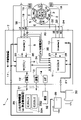
- the block diagram which shows the motor control system and the motor control apparatus by embodiment.
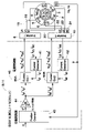
- the block diagram which shows the control process which generates torque to a motor at a normal time.
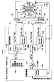
- the block diagram which shows the control process which generates a forward torque by a torque command and a reverse torque by a reverse torque command in a motor.
- the flow chart which shows the process of generating a forward torque by a torque command and a reverse torque by a reverse torque command in a motor.
- the characteristic diagram which shows an example of the 1st system motor current by a torque command, the 2nd system motor current by a reverse torque command, and the time change of a motor angle.
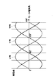
- the characteristic diagram which shows an example of the relationship between a motor electric angle and a phase current (U phase, V phase, W phase).
- a motor control system 1 mounted on a vehicle includes a brake motor 2 as a motor and a motor control device 7 as a motor controller. Further, the motor control system 1 may also include a higher-level control device 33 as a vehicle controller (vehicle controller). In the embodiment, the superordinate control device 33 corresponds to an integrated controller that determines the motion control of the vehicle.
- the upper control device 33 is referred to as an integrated control device 33.
- the brake motor 2 controls (drives) an electric brake mechanism (not shown) that applies braking force to the vehicle.
- the electric brake mechanism corresponds to, for example, an electric disc brake provided with an electric caliper that presses a brake pad against a disc rotor by an electric motor.
- the brake motor 2 includes a stator 3 as a stator and a rotor 4 as a permanent magnet rotor provided rotatably in the center of the stator 3.
- the rotor 4 of the brake motor 2 is connected to, for example, a rotary shaft of a rotary linear motion conversion mechanism (not shown).
- the rotation of the brake motor 2 (rotor 4) is converted into a linear motion by the rotation linear motion conversion mechanism, and the brake pad of the electric brake mechanism is brought close to and separated from the disc rotor.
- the brake motor 2 is provided with two winding sets 5 and 6 in order to ensure redundancy. That is, the brake motor 2 is composed of a first winding set 5 composed of star-connected three-phase windings U1, V1 and W1, and a second winding composed of star-connected three-phase windings U2, V2 and W2. It is configured as a 3-phase synchronous motor with a set of 6, in other words, a 6-phase motor with a 3-phase double winding (a 6-phase motor that generates torque with two 3-phase coils for one rotor 4). Has been done. The first winding set 5 and the second winding set 6 are provided on the stator 3 in a state of being insulated from each other.
- the electric brake mechanism is not limited to the electric disc brake (electric caliper).
- the electric brake mechanism (electric brake) is a hydraulic disc brake equipped with an electric motor (hydraulic disc brake with an electric parking brake function), and a cable that applies the parking brake by pulling the cable with the electric motor.
- a puller type electric parking brake may be used. That is, the electric brake (electric brake mechanism) presses (propulses) the friction member (pad, shoe) against the rotating member (rotor, drum) based on the drive of the electric motor (electric actuator), and applies and releases the braking force.
- the electric brake mechanism (electric brake) is, for example, an electric booster that controls the pressure of the brake fluid and pressurizes and brakes the cylinder devices (for example, the brake caliper and the piston) arranged on each of the four wheels of the vehicle.
- the cylinder devices for example, the brake caliper and the piston
- it may be a hydraulic pressure supply device.
- the motor control device 7 as a motor controller controls the brake motor 2. More specifically, the motor control device 7 drives and controls the windings U1, V1, W1 of the first winding set 5 of the brake motor 2 and the windings U2, V2, W2 of the second winding set 6. do.
- the motor control device 7 includes a first drive control system (first motor drive unit 8, first control unit 9) that drives and controls the first winding set 5 (U1, V1, W1), and a second. It includes a second drive control system (second motor drive unit 10, second control unit 11) that drives and controls the winding set 6 (U2, V2, W2).
- the motor control device 7 includes a first motor drive unit 8, a first control unit 9, a second motor drive unit 10, and a second control unit 11. Further, the motor control device 7 includes a first communication interface 12, a second communication interface 13, and an interface (I / F) 14.
- the first motor drive unit 8 drives the brake motor 2.
- the first motor drive unit 8 is composed of, for example, an inverter circuit.
- the first motor drive unit 8 is connected to the first power supply 29 of the vehicle such as a power storage device (battery) via the first DC power line 17.
- the first motor drive unit 8 is connected to the windings U1, V1, W1 of the first winding set 5 of the brake motor 2 via the U1 phase power line 18, the V1 phase power line 19, and the W1 phase power line 20. It is connected.
- the first motor drive unit 8 is connected to the first control unit 9 via signal lines 25 and 26.
- the first motor drive unit 8 (inverter circuit) is configured to include a plurality of switching elements including, for example, a transistor, a field effect transistor (FET), an insulated gate bipolar transistor (IGBT), and the like.
- the opening / closing of each switching element of the first motor drive unit 8 (inverter circuit) is controlled based on a command signal (for example, a pulse signal) from the first control unit 9.
- a command signal for example, a pulse signal
- the first motor drive unit 8 (inverter circuit) generates three-phase (U-phase, V-phase, W-phase) AC power from DC power based on a command signal from the first control unit 9.
- the generated AC power is supplied to the first winding set 5 (each winding U1, V1, W1) of the brake motor 2.
- the first control unit 9 is connected to the first motor drive unit 8.
- the first control unit 9 corresponds to the first motor ECU (M_ECU_1), and includes, for example, a power circuit (Power Management IC), a microcomputer, and a driver circuit (Pre Driver).
- the first control unit 9 is connected to the first power supply 29 of the vehicle via the first DC power line 17 and is connected to the first motor drive unit 8 via the signal lines 25 and 26.
- the first control unit 9 drives the brake motor 2 (forward rotation, reverse rotation) by controlling (switching control) the first motor drive unit 8 (inverter circuit).
- the first control unit 9 is connected to a rotation sensor 15 for feedback-controlling the rotation of the rotor 4 of the brake motor 2.
- the rotation sensor 15 detects, for example, the rotation angle of the rotor 4 of the brake motor 2.
- the first control unit 9 is connected to the vehicle data bus 31 which is a communication line via the first communication interface 12.
- the vehicle data bus 31 constitutes, for example, a CAN (Controller Area Network) as a communication network mounted on the vehicle body.
- various ECUs such as an integrated control device 33, a suspension control device (not shown), and a steering control device (not shown) are connected to each other by the vehicle data bus 31. Performs multiplex communication in the vehicle.
- the second motor drive unit 10 also drives the brake motor 2 in the same manner as the first motor drive unit 8.
- the second motor drive unit 10 is also configured by, for example, an inverter circuit.
- the second motor drive unit 10 is connected to the second power source 30 of the vehicle such as a power storage device (battery) via the second DC power line 21.
- the second motor drive unit 10 passes through the U2 phase power line 22, the V2 phase power line 23, and the W2 phase power line 24 to the windings U2, V2, W2 of the second winding set 6 of the brake motor 2. It is connected.
- the second power supply 30 is a power supply (power supply of another system) different from the first power supply 29 connected to the first motor drive unit 8 and the first control unit 9. Redundancy is ensured by making the power supply path a double system in this way.
- the second motor drive unit 10 is connected to the second control unit 11 via the signal lines 27 and 28.
- the second motor drive unit 10 (inverter circuit) is also configured to include a plurality of switching elements including, for example, a transistor, a field effect transistor (FET), an insulated gate bipolar transistor (IGBT), and the like.
- the opening / closing of each switching element of the second motor drive unit 10 (inverter circuit) is controlled based on a command signal (for example, a pulse signal) from the second control unit 11.
- a command signal for example, a pulse signal
- the second motor drive unit 10 (inverter circuit) generates three-phase (U-phase, V-phase, W-phase) AC power from DC power based on a command signal from the second control unit 11.
- the generated AC power is supplied to the second winding set 6 (each winding U2, V2, W2) of the brake motor 2.
- the second control unit 11 is connected to the second motor drive unit 10.
- the second control unit 11 is also called an ECU (Electronic Control Unit) and includes a microcomputer that serves as an arithmetic circuit (CPU).
- the second control unit 11 corresponds to the second motor ECU (M_ECU_2), and includes, for example, a power circuit (Power Management IC), a microcomputer, and a driver circuit (Pre Driver).
- the second control unit 11 is connected to the second power supply 30 of the vehicle via the second DC power line 21 and is connected to the second motor drive unit 10 via the signal lines 27 and 28.
- the second control unit 11 drives the brake motor 2 (forward rotation, reverse rotation) by controlling (switching control) the second motor drive unit 10 (inverter circuit).
- the second control unit 11 is connected to a rotation sensor 16 for feedback-controlling the rotation of the rotor 4 of the brake motor 2.
- the rotation sensor 16 detects, for example, the rotation angle of the rotor 4 of the brake motor 2.
- the rotation sensor 16 is also a rotation sensor different from the rotation sensor 15 connected to the first motor drive unit 8. This ensures redundancy.
- the second control unit 11 is connected to the vehicle data bus 31 via the second communication interface 13. Further, the second control unit 11 is connected to the speed sensor 32 via the interface 14.
- the speed sensor 32 is, for example, a sensor that detects the speed of the vehicle.
- the integrated control device 33 is connected to the first control unit 9 and the second control unit 11. That is, the integrated control device 33 is connected to the first control unit 9 and the second control unit 11 via, for example, a vehicle data bus 31 called CAN.
- the integrated control device 33 is, for example, an integrated control device (integrated ECU) that determines vehicle motion control for moving a vehicle with respect to a target locus obtained from an automatic driving control device (automated driving ECU).
- the integrated control device 33 includes each actuator control device (actuator ECU), for example, a motor drive device (motor drive ECU), a brake control device (brake ECU), a steering control device (steering ECU), a suspension control device (suspension ECU), and the like. (For example, a control command related to automatic operation) is output.
- the motor control device 7 also serves as, for example, both a motor drive device (motor drive ECU) that drives the brake motor 2 and a brake control device (brake ECU) that performs integrated control of the brake. That is, the motor control device 7 (brake motor control ECU) is integrally configured as a control device having both a motor drive function and a brake control function.
- the motor drive device (motor drive ECU) and the brake control device (brake ECU) may be configured separately (separately).
- the integrated control device 33 is also called a central control device (central ECU), and corresponds to a higher-level control device of the motor control device 7.
- the integrated control device 33 is also configured to include a microcomputer that serves as an arithmetic circuit (CPU).
- the integrated control device 33 is configured by, for example, a dual core (dual circuit) so that the same processing can be performed in parallel and the processing results can be monitored for differences. That is, the integrated control device 33 is composed of two control units 33A and 33B (first central ECU (C_ECU_1) and second central ECU (C_ECU_2)).
- the first control unit 9 and the second control unit 11 are each connected to the integrated control device 33. Further, the second control unit 11 is connected to the first control unit 9 via a communication line 34 (communication line between CPUs).
- the second control unit 11 monitors the state of the first motor drive unit 8. More specifically, the second control unit 11 monitors the state of the phase current in the first motor drive unit 8.
- the phase current monitor circuit 35 is connected to the U1 phase power line 18, the V1 phase power line 19, and the W1 phase power line 20 of the first motor drive unit 8.
- the phase current monitor circuit 35 is connected to the second control unit 11, and the second control unit 11 monitors the phase current of the first motor drive unit 8 by the phase current monitor circuit 35.
- the second control unit 11 determines that the first control unit 9 is abnormal when the monitor value in the phase current monitor circuit 35 is out of the normal range and the control cannot be performed according to the control command.
- Patent Document 1 describes a technique for driving a motor having two coils and one rotor by controlling two inverter circuits.
- Patent Document 1 describes a control technique for suppressing a decrease in the total output of the motor when a failure of the inverter circuit occurs, it is for suppressing the variation in torque generated by the two coils in the normal state. There is no description about the technology.
- each system is manufactured. It is difficult for the characteristics to be the same due to variations. Therefore, for example, even if the CPU executing the motor control algorithm detects the same current value, the torque generated by each system for the rotor at that time may not be the same, and a difference may occur. be. This difference does not exist in the configuration in which the rotor is driven by one system of inverters, sensors, and coils (hereinafter, also referred to as one system configuration). Therefore, in the case of a configuration of two or more systems, torque ripple and torque control error increase as compared with the configuration of one system, and there is a concern that responsiveness and sound vibration performance may deteriorate.
- each inverter (first winding set 5 and second winding set 6) generates torque in the opposite direction without rotating the rotor 4 for the coils of both systems (first winding set 5 and second winding set 6).
- 1 Motor drive unit 8 and 2nd motor drive unit 10) are controlled to energize.
- the current detection values of the current sensors 41 and 42 (FIGS. 2 and 3) of both systems at that time are compared, and the difference is used as a recognition torque error to correct the current value.
- the variation in torque generated by the two coils (first winding set 5 and second winding set 6) is corrected.
- the embodiment it is possible to suppress the difference in torque generated in each system, and it is possible to reduce the ripple error (torque pulsation) of torque control.
- the responsiveness is improved, and the control performance and sound vibration performance of the brake motor 2 and, by extension, the electric brake mechanism serving as the actuator can be improved.
- the same performance response performance, control performance, sound vibration performance
- the configuration of this one system can be realized by the configuration of two or more systems. Therefore, the need for an expensive element is reduced, and the cost can be reduced.
- the two control units 9 and 11 are virtually represented as one control unit, but in the embodiment, as shown in FIG. Also, two control units 9 and 11 are provided.
- the present invention is not limited to this, and the process performed by the first control unit 9 may be performed by the second control unit 11, and the process performed by the second control unit 11 may be performed by the first control unit 9.
- both the processing performed by the first control unit 9 and the processing performed by the second control unit 11 are performed by the control unit 9 (11) of either the first control unit 9 or the second control unit 11. ) May be used.
- the brake motor 2 includes two coils (first winding set 5, second winding set 6) for one rotor 4.
- the brake motor 2 is controlled by a motor that generates torque by energizing two coils (first winding set 5 and second winding set 6).
- the two systems of coils (first winding set 5 and second winding set 6) are connected to inverters of different systems (first motor drive unit 8 and second motor drive unit 10), and are connected to different systems.
- the current is detected by the current sensors 41 and 42, and the motor is controlled.
- the power supplies 29 and 30 have a redundant configuration so that the motor control can be continued as much as possible in case of a failure. That is, the first and second motor drive units 8 and 10, each of which is composed of an inverter, are connected to separate power supplies 29 and 30, respectively. Although not shown, for example, when one of the power supplies 29 and 30 fails, a power supply circuit is provided so as to cut off the electrical connection with the power supply 29 (30) on the failed side, and this power supply is provided. Both motor drive units 8 and 10 may be connected to the circuit.
- the configuration has two CPUs (microcomputers), that is, the configuration has two control units 9 and 11 of the first control unit 9 and the second control unit 11, and the first control.
- the unit 9 and the second control unit 11 are connected by a communication line 34 (communication line between CPUs).
- the control units 9 and 11 including two CPUs control the first motor drive unit 8 and the second motor drive unit 10 which are inverters, and have three independent phases.
- the first winding set 5 and the second winding set 6 which are the coils of the above are energized.
- the currents flowing through the first winding set 5 and the second winding set 6 are detected by the current sensors 41 and 42, and the motor angle of the brake motor 2 is a rotation sensor 15 that serves as an angle sensor (motor angle sensor).
- detecting by 16 and 16 a feedback loop for generating a desired motor torque is constructed.
- the first current sensor 41 detects the current of the first winding set 5, and the second current sensor 42 detects the current of the second winding set 6.
- Three current sensors 41 and 42 can be arranged in each system so as to directly detect the current flowing through the first winding set 5 and the second winding set 6, each of which is a three-phase coil.
- the number of current sensors may be two or one by appropriately setting the location of the current sensor and the current detection timing by a known technique. That is, it suffices if the three-phase current can be directly detected or estimated.
- FIG. 2 shows a control process executed in the control units 9 and 11 in order to generate torque in the brake motor 2 at normal times.
- the control units 9 and 11 include a position controller 43, a current commander 44, and a current controller 45 (first current controller 45A, second current controller 45B).
- the position controller 43 calculates the torque command T * based on the deviation between the motor angle command C instructed by the upper control and the motor angle detected from the rotation sensors 15 and 16.
- the position controller 43 outputs the calculated torque command T * to the current commander 44.
- each of the first winding set 5 and the second winding set 6 may output half of the desired torque to be output by the brake motor 2. Therefore, in the current commander 44, the torque command T * is halved (1/2), and the current command id1 * , iq1 * , id2 * , and iq2 * are calculated (distributed) using the torque constant value K of the motor. do.
- the current commander 44 outputs the calculated (distributed) current commands id1 * , iq1 * , id2 * , iq2 * to the current controller 45 (first current controller 45A, second current controller 45B).
- the current controller 45 (first current controller 45A, second current controller 45B) energizes the first winding set 5 of the first system and the second winding set 6 of the second system, respectively. Control.
- the current controller 45 (first current controller 45A, second current controller 45B)
- the three-phase voltage value is determined based on the angular phase), and the first motor drive unit 8 and the second motor drive unit 10 are controlled.
- the first current controller 45A which is the first system side (for example, the first control unit 9 side) of the current controller 45
- the motor angle (electrical angular phase) detected by the rotation sensor 15 the three-phase voltage values vU1 * , vV1 * , and vW1 * are determined, and the first motor drive unit 8 is controlled.
- the second current controller 45B which is the second system side (for example, the second control unit 11 side) of the current controller 45
- the three-phase currents iU2, iV2, iW2 detected or estimated by the current sensor 42 Based on iq2) and the motor angle (electrical angle phase) detected by the rotation sensor 16
- the three-phase voltage values vU2 * , vV2 * , and vW2 * are determined, and the second motor drive unit 10 is controlled.
- the torque command T * calculated based on the motor angle command C from the upper control is halved, and the motor torque to be realized in each system is calculated.
- the command from the upper control is, for example, speed. It may be a command or a motor torque command.
- the distribution of the motor torque command to be input to the current commander 44 may also be variable depending on, for example, the temperature. Further, for example, when one system fails, the distribution on the failed side may be set to 0 while the normal side is fixed at 50%. In this case as well, the distribution on the normal side may be temporarily allocated as needed. It may be 50% or more.
- the process for controlling the current generally needs to be executed at high speed. Therefore, when the control units 9 and 11 exist independently for the respective motor drive units 8 and 10, it is preferable to implement the process for controlling the current in the respective control units 9 and 11. That is, it is preferable that the current control process on the first system side is mounted on the first control unit 9, and the current control process on the second system side is mounted on the second control unit 11.
- the process of calculating the current command or the motor torque command to be realized in each system based on the motor angle command is executed only by one CPU (first control unit 9 or second control unit 11).
- the calculation result of the command may be transmitted to the other CPU (second control unit 11 or first control unit 9) using inter-CPU communication (communication line 34).
- control units 9 and 11 may be independently executed by each CPU (control units 9 and 11), and only the torque command to be realized in each system may be used by each CPU (control units 9 and 11). ..
- the results calculated independently by each CPU (control units 9 and 11) are transmitted using inter-CPU communication (communication line 34), and are compared and selected by each CPU (control units 9 and 11). You may.
- the control process of FIG. 4 is repeatedly executed, for example, in a predetermined control cycle (for example, 10 ms).
- S1 determines whether or not the current value correction process may be executed. That is, in S1, it is determined whether or not the condition for performing the current value correction process is satisfied.
- torques in opposite directions are generated in the coils of both systems (first winding set 5, second winding set 6).
- the brake motor 2 does not output torque. Therefore, it is necessary to execute the current value correction process in a situation where it is permissible not to generate the torque of the brake motor 2.
- the brake motor 2 used for braking the vehicle corrects the current value, it is necessary to immediately return to the normal control when the braking is not performed or when the necessity of braking is detected.
- the vehicle is stopped (it is stopped).
- the brake motor 2 is the drive source of the electric booster, or the brake motor 2 is the drive source of the hydraulic pressure supply device (ESC). That is, the pressure of the brake fluid is controlled by the electric booster or the hydraulic pressure supply device based on the drive of the brake motor 2, and the cylinder devices (brake calipers and pistons) arranged on the four wheels of the vehicle are pressurized to brake.
- the cylinder devices brake calipers and pistons
- the brake motor 2 is the drive source of the electric caliper arranged on each of the four wheels of the vehicle. That is, a braking force is directly generated by directly moving the piston based on the drive of the brake motors 2 arranged on each of the four wheels of the vehicle and pressing the brake pad against the brake disc, and also serves as a parking brake function.
- the braking force of the four wheels is distributed and the current value correction process is executed so that the vehicle can be kept stationary. That is, it is possible to set the calipers for releasing the braking torque in order and execute the correction processing of the current value of each brake motor 2 in that order.
- the necessity of braking and the running state of the vehicle can be determined based on the signal acquired from the vehicle network (vehicle data bus 31) in addition to the stroke sensor that detects the operation of the brake pedal.
- the correction of the current value may be performed only when a certain time has elapsed from the previous correction. Further, in either case, the correction of the current value may be performed at the time of pre-shipment calibration when the braking actuator such as the electric booster, the hydraulic pressure supply device, and the electric caliper is manufactured. Further, the correction of the current value may be performed at the time of pre-shipment inspection of the vehicle after the braking actuator (for example, the electric booster, the hydraulic pressure supply device, the electric caliper) is incorporated in the vehicle.
- the correction of the current value may be performed on the condition that the execution request from the diagnostic tool or the like is received at the time of inspection after the vehicle is shipped. At this time, based on the corrected result, the current value may be periodically corrected after being mounted on the vehicle, and the corrected value may be updated. In any case, the correction of the current value may be started by the manual start operation of the clerk, or may be started automatically without the manual start operation.
- S1 can be performed by the control units 9 and 11, for example, by the integrated control device 33 which is a higher-level control device, and when the condition is satisfied (when "YES" in S1).
- a command to correct the current value may be output to the control units 9 and 11, and the subsequent processing may be performed by the control units 9 and 11.
- the rotor 4 of the brake motor 2 is moved to the motor angle for correction. This process is performed as necessary. That is, if the current motor angle is the position to be corrected, it is not necessary to move.
- the motor angle for correcting the current value can be maintained without outputting the motor torque, and it is preferable that the motor angle can be changed with the smallest possible motor torque.
- the motor that corrects the current value is the brake motor 2 used for braking, that is, the brake motor 2 is the drive source of the braking actuator such as the electric booster, the hydraulic pressure supply device, and the electric caliper. In this case, it is desirable that the motor angle for correcting the current value is a region where the brake fluid pressure for braking or the pressing force of the brake pad is not generated.
- the motor is a three-phase brushless motor
- the current energizing the three-phase coil is applied to the position of the magnet arranged in the rotor 4. It is necessary to switch according to the motor electric angle). Therefore, it is preferable to set the motor electric angle at which only two phases need to be energized to generate torque as the motor angle for correction. That is, the correction of the current value is preferably performed when the motor electric angles in FIG. 6 are 0 °, 30 °, 60 °, 90 °, 120 °, 150 °, and 180 °.
- the coil for generating torque for correction is only two phases, and the current variation of each phase can be clarified by repeating the correction by shifting the motor electric angle by 30 °. , The accuracy of correction can be improved.
- the electric angle (motor electric angle) corresponds to the angle of the alternating current flowing through the coil.
- the feedback control of the motor angle command using the above-mentioned inverters of both systems is performed until the motor electric angle of the command is reached.
- the motor angle command corresponds to the motor electrical angle in which it is preferable to correct the current value.
- the brake motor 2 (rotor 4) is driven by feedback control until the motor electric angle corresponding to the command is reached.
- the motor currents of both systems when the change in the motor angle is statically determinate (stationary) with respect to the increase in the current of the first system are recorded by the processing of S6. That is, in S6 following S5, the currents of the first system and the second system are stored, respectively.
- the current value to be recorded is preferably, for example, the average value of the current values during a certain period of time during statically determinate, or the result of filtering processing.
- the current of the second system is the value when the current of the first system is gradually increased from 0 and the current of the first system is increased from the vicinity of the maximum value.
- Two types are recorded, the value when the value is gradually reduced. This is for removing the influence of the mechanical friction torque existing in the braking actuator, and it is preferable to use the average value of the current at the time of increase and the current at the time of decrease as the current for correction.
- S7 it is determined whether or not the command pattern at the specified current by the processing of S4-S6 is completed. That is, the current is gradually increased and decreased by the current command, and it is determined whether or not this is performed by the required amount at different electric angles.
- the processing of S4-S6 is performed when the control modes (current control mode, position control mode) of the first system and the second system are reversed, and when the holding positions are different depending on the motor electric angle shown in FIG. It can be repeated once.
- the control modes current control mode, position control mode
- the holding positions are different depending on the motor electric angle shown in FIG. It can be repeated once.
- the shunt resistance generally used as a current sensor is not affected by the direction in which the current flows.
- control modes of the first system and the second system do not need to be reversed. Further, it is considered sufficient to make the difference in the motor electric angles at three types of adjacent angles every 30 ° (for example, the motor electric angles 0 °, 30 °, 60 °).
- Iu2 and Iv2 are assumed to be the average values of the currents at the time of increase and the above-mentioned decrease. Further, at this time, since the signs of Iu1 and Iu2 and Iv1 and Iv2 are opposite, the differences ⁇ Iu and ⁇ Iv can be calculated by, for example, the following equations 1 and 2.
- the difference ⁇ Iu and ⁇ Iv are calculated as ⁇ Iu ′, ⁇ Iv ′, and ⁇ Iw ′ in which the positive and negative of the phase current are opposite to each other in addition to ⁇ Iw when considering the motor electric angles of three adjacent types every 30 °.
- the correction value of each phase current may be the average value of each. As described above, since the motor current exists at a plurality of points in a stepped manner with respect to the condition of one motor electric angle, Iu1, Iv1, Iw1, etc. are all arrays having a plurality of data. This correction value may be used as a correction value for the current detection value of the first system, or may be used as a correction value for the current detection value of the second system. Further, the calculated correction value may be distributed to the first system and the second system for use.
- the motor control system of the embodiment includes a brake motor 2 as a motor and a motor control device 7 as a motor controller for controlling the brake motor 2.
- the motor control device 7 includes a first motor drive unit 8, a first control unit 9, a second motor drive unit 10, and a second control unit 11.
- the brake motor 2 controls, for example, an electric brake mechanism that applies a braking force to the vehicle.
- the first motor drive unit 8 drives the first winding set 5 as the first system coil of the brake motor 2.
- the second motor drive unit 10 drives the second winding set 6 as the second system coil of the brake motor 2.
- the first control unit 9 is connected to the first motor drive unit 8.
- the second control unit 11 is connected to the second motor drive unit 10.
- the first control unit 9 has a torque command (first torque command) (three-phase voltage values vU1 * , vV1 * based on the correction processing current command id1 * , iq1 * in FIG. 3). , VW1 * ) is output to the first motor drive unit 8.
- the second control unit 11 has a reverse torque command (second torque command) for generating torque in the opposite direction to the torque command when a preset condition is satisfied (current command id2 * , iq2 * in FIG. 3).
- the three-phase voltage values vU2 * , vV2 * , vW2 * ) based on the above are output to the second motor drive unit 10.
- the second control unit 11 outputs, for example, a reverse torque command so that the rotational position of the brake motor 2 is maintained.
- the first control unit 9 receives a torque command (first torque command) (correction processing current command id1 in FIG. 3) when a preset condition is satisfied.
- the three-phase voltage values vU1 * , vV1 * , vW1 * ) based on * and iq1 * are output to the first motor drive unit 8, and the second control unit 11 issues a torque command when the preset conditions are satisfied.
- the second motor drives the reverse torque command (second torque command) (three-phase voltage values vU2 * , vV2 * , vW2 * based on the current commands id2 * and iq2 * in Fig. 3) to generate torque in the opposite direction.
- the second control unit 11 outputs a reverse torque command so that the rotational position of the brake motor 2 is maintained, for example.
- the control current is corrected based on the difference ( ⁇ Iu, ⁇ Iv) from the current value (Iu2, Iv2).
- the first control unit 9 sets the control current of the first motor drive unit 8 based on the difference ( ⁇ Iu, ⁇ Iv) between the first current value (Iu1, Iv1) and the second current value (Iu2, Iv2).
- the correction or the second control unit 11 corrects the control current of the second motor drive unit 10.
- control current of the first motor drive unit 8 by the first control unit 9 is corrected, or the control current of the second motor drive unit 10 by the second control unit 11 is corrected by the angle of the motor electric angle of the brake motor 2. Perform multiple times with different differences (eg, at 3 different angles of 30 ° in close proximity).
- the second control unit 11 requests a reverse torque command so that the rotation position of the brake motor 2 is held at the preset rotation position.
- the first control unit 9 controls the current flowing through the first winding set 5 by the torque command so that the absolute value of the torque command and the absolute value of the reverse torque command become equal, and the second control unit 11 controls the current.
- the reverse torque command controls the current flowing through the second winding set 6.
- the first control unit 9 executes current command control that gradually increases the current energized to the first winding set 5 by a torque command, and the second control unit 11 receives a reverse torque command.
- the position feedback command control is executed so that the rotation position of the brake motor 2 stands by at the preset rotation position.
- the first control unit 9 executes a current command control that gradually increases the current energized to the first winding set 5 by a torque command and then gradually decreases the current, and gradually increases the current.
- the first current value (Iu1, Iv1) and the second current value (Iu2, Iv2) obtained from the average value of the current value detected at the time and the current value detected when the current value was gradually decreased.
- the control current is corrected based on the difference ( ⁇ Iu, ⁇ Iv).
- the preset conditions for correcting the control current are when the vehicle is not braking or when the vehicle is stopped.
- the preset condition is that the parking brake mechanism that holds the braking force is locked when the vehicle is stopped.
- the preset conditions may be pre-shipment inspection or vehicle inspection.
- the first control unit 9 when the preset conditions are satisfied, the first control unit 9 outputs the torque command (first torque command) to the first motor drive unit 8 and the second control unit 9.
- the unit 11 outputs a reverse torque command (second torque command) in the opposite direction to the torque command to the second motor drive unit 10. Therefore, it is possible to acquire the current value for correction by providing a configuration for executing the control of applying the forward torque according to the torque command and the reverse torque according to the reverse torque command to the brake motor 2 under preset conditions. Become. As a result, it is possible to suppress variations in torque generated by the two coils, that is, the first winding set 5 and the second winding set 6.
- the control current is corrected based on the difference ( ⁇ Iu, ⁇ Iv) from the detected second current value (Iu2, Iv2) ”.
- the control current of the first motor drive unit 8 by the first control unit 9 is based on the difference ( ⁇ Iu, ⁇ Iv) between the first current value (Iu1, Iv1) and the second current value (Iu2, Iv2).
- the control current of the second motor drive unit 10 by the second control unit 11 is corrected.
- the correction of the control current is executed a plurality of times depending on the angle difference of the motor electric angle of the brake motor 2, so that the accuracy of the correction can be improved.
- the second control unit 11 requests a reverse torque command so that the rotation position of the brake motor 2 is held at the preset rotation position. Therefore, the rotation position of the brake motor 2 can be held at a preset rotation position based on the reverse torque command of the second control unit 11.
- the current flowing through the first winding set 5 and the current flowing through the second winding set 6 are controlled based on the "torque command" and the "reverse torque command having an absolute value equal to the absolute value of the torque command". Will be done.
- the rotational position of the brake motor 2 can be held at a preset position.
- the second control unit 11 executes the position feedback command control by the reverse torque command for each current of each stage of the current command control by the torque command of the first control unit 9. Therefore, the rotation position of the brake motor 2 can be held at a preset rotation position for each current of each stage of the current command control. That is, by controlling the current of the first system coil and controlling the position of the second system coil, the rotation of the motor can be maintained for each stage of the current.
- control current can be corrected both "when the current is gradually increased” and “when the current is gradually decreased” by the current command control. As a result, the accuracy of correction can be improved.
- the brake motor 2 is loaded with a forward torque according to a torque command and a reverse torque according to a reverse torque command. Therefore, it is possible to suppress variations in the torque of the brake motor 2 that controls the electric brake mechanism that applies the braking force to the vehicle.
- the preset condition for correcting the control current is when the vehicle is not braking or when the vehicle is stopped. Therefore, when the vehicle is not braking or stopped, the brake motor 2 can be applied with a forward torque according to a torque command and a reverse torque according to a reverse torque command. Further, according to the embodiment, the preset condition is that the parking brake mechanism for holding the braking force is locked when the vehicle is stopped. Therefore, when the parking brake mechanism when the vehicle is stopped is locked, a forward torque according to a torque command and a reverse torque according to a reverse torque command can be applied to the brake motor 2.
- the preset conditions may be used for pre-shipment inspection or vehicle inspection.
- a forward torque according to the torque command and a reverse torque according to the reverse torque command can be applied to the brake motor 2 at the time of pre-shipment inspection or vehicle inspection.
- the pre-shipment inspection corresponds to, for example, the inspection before shipping from the manufacturing factory of the braking actuator (for example, the electric booster, the hydraulic pressure supply device, the electric caliper) in which the brake motor 2 is incorporated to the automobile assembly factory.
- the pre-shipment inspection corresponds to, for example, an inspection before shipping from an automobile assembly plant in which a braking actuator is incorporated to a vehicle dealer.
- the vehicle inspection corresponds to, for example, the initial diagnosis after shipment, more specifically, the initial vehicle inspection performed before delivery to the vehicle purchaser.
- the correction can be performed based on the instruction from the diagnostic tool. Further, for example, the correction may be performed when the vehicle purchaser starts using the vehicle after the vehicle inspection or the like. In this case, for example, the correction may be performed when the motor control system (motor control device 7) is started from the sleep state and the initial check is performed.
- the present invention is not limited to this, and can be used for a plurality of systems having a double system or more, such as a triple system, a quadruple system, and the like.
- the second control unit 11 monitors the first control unit 9, that is, the second control unit 11 monitors the phase current of the first motor drive unit 8 by the phase current monitor circuit 35.
- the case was explained as an example.
- the case where the monitoring side is the second control unit and the monitored side is the first control unit has been described as an example.
- the present invention is not limited to this, and for example, the monitoring side may be used as the first control unit and the monitored side may be used as the second control unit.
- the side that outputs the torque command corresponds to the first system (first control unit, first motor drive unit, first system coil) and reverse torque.
- the side that outputs the command corresponds to the second system (second control unit, second motor drive unit, second system coil).
- the torque command and the reverse torque command merely define the rotation direction of the motor with either one as a reference, and the reference may be either a forward rotation direction or a reverse rotation direction.
- the motor driven by the first motor drive unit 8 and the second motor drive unit 10 is a brake motor 2, that is, a brake motor 2 that controls an electric brake mechanism that applies braking force to the vehicle. It was explained by giving an example.
- the motor driven by the first motor drive unit and the second motor drive unit may be, for example, a steering motor that controls (drives) the steering actuator of the vehicle.
- the steering motor can be driven by the first motor drive unit connected to the first control unit and the second motor drive unit connected to the second control unit.
- the steering may move when the torque command and the reverse torque command are output. Therefore, for example, when the preset conditions are when the vehicle is braking, when the vehicle is not braking, or when the vehicle is stopped, the driver may feel uncomfortable. Therefore, in the case of the steering motor, the preset conditions can be, for example, pre-shipment inspection or vehicle inspection.
- the motor driven by the first motor drive unit and the second motor drive unit is not limited to the brake motor and the steering motor, but is a motor for driving various actuators mounted on the vehicle (duality). It can be a motor that needs to be secured.
- the integrated control device 33 integrated ECU, central
- the vehicle controller vehicle controller
- the integrated control device 33 integrated ECU, central
- the vehicle controller vehicle controller
- the vehicle controller vehicle controller
- the vehicle controller does not have to be a control device other than the integrated control device 33, such as a steering control device and a suspension control device, that is, a higher-level control device.
- various control devices (ECUs) mounted on the vehicle can be used.
- the motor control device As the motor control device, the control method of the motor control device, and the motor control system based on the above-described embodiment, for example, the ones described below can be considered.
- the first aspect is a motor control device that controls a motor having two coils, and when a preset condition is satisfied with a first motor drive unit that drives the first system coil of the motor. , The first control unit that outputs the first torque command to the first motor drive unit, the second motor drive unit that drives the second system coil of the motor, and the preset conditions are satisfied. It is a motor control device including a second control unit that outputs a second torque command for generating a torque in the opposite direction to the first torque command to the second motor drive unit.
- acquisition of a current value for correction is provided by providing a configuration for executing control of applying a forward torque according to a torque command and a reverse torque according to a reverse torque command to the motor under preset conditions. Will be possible. As a result, it is possible to suppress variations in torque generated by the two coils.
- the first current value which is the detection value of the current flowing through the first system coil by the first torque command
- the second system coil by the second torque command.
- the first control unit corrects the control current of the first motor drive unit based on the difference between the second current value, which is the detected value of the flowing current, or the second control unit corrects the control current of the first motor drive unit. Correct the control current of the motor drive unit.
- the first control unit corrects the control current of the first motor drive unit based on the difference between the first current value and the second current value, or the second control unit is the second. By correcting the control current of the motor drive unit, it is possible to suppress the variation in torque generated by the two coils.
- the second control unit requests the second torque command so that the rotation position of the motor is held at a preset rotation position.
- the rotation position of the motor can be held at a preset rotation position based on the reverse torque command of the second control unit.
- the first control unit receives the first torque command so that the absolute value of the first torque command and the absolute value of the second torque command become equal to each other.
- the second control unit controls the current flowing through the first system coil, and the second control unit controls the current flowing through the second system coil by the second torque command.
- the current flowing through the first system coil and the current flowing through the second system coil are based on the "torque command” and the "reverse torque command having an absolute value equal to the absolute value of this torque command".
- the first control unit executes current command control in which the current energized to the first system coil is gradually increased by the first torque command, and the first control unit performs the current command control.
- the 2 control unit executes position feedback command control so that the rotation position of the motor stands by at a preset rotation position by the second torque command.
- the second control unit executes the position feedback command control by the reverse torque command for each current of each stage of the current command control by the torque command of the first control unit. Therefore, the rotation position of the motor can be held at the preset rotation position for each current of each stage of the current command control. That is, by controlling the current of the first system coil and controlling the position of the second system coil, the rotation of the motor can be maintained for each stage of the current.
- the first control unit gradually increases the current energized to the first system coil by the first torque command, and then gradually decreases the current.
- the first current value obtained from the average value of the current value detected when the command control was executed and the stepwise increase and the current value detected when the command control was stepwise decreased, and the above.
- the control current of the first motor drive unit is corrected based on the difference between the second current value, which is the detected value of the current flowing through the second system coil, by the reverse second torque command.
- control current can be corrected in both "when the current is gradually increased” and “when the current is gradually decreased” by the current command control. As a result, the accuracy of correction can be improved.
- the motor is a brake motor that controls an electric brake mechanism that applies a braking force to the vehicle. According to this seventh aspect, it is possible to suppress variations in the torque of the brake motor.
- the preset condition is when the vehicle is not braked or when the vehicle is stopped. According to this eighth aspect, when the vehicle is not braking or the vehicle is stopped, a forward torque according to a torque command and a reverse torque according to a reverse torque command can be applied to the brake motor.
- the preset condition is that the parking brake mechanism for holding the braking force is locked when the vehicle is stopped.
- the parking brake mechanism when the vehicle is stopped can apply a forward torque according to a torque command and a reverse torque according to a reverse torque command to the brake motor in a locked state.
- the preset condition is at the time of pre-shipment inspection or vehicle inspection.
- a forward torque according to a torque command and a reverse torque according to a reverse torque command can be applied to the motor at the time of pre-shipment inspection or vehicle inspection.
- the first control unit corrects the control current of the first motor drive unit, or the second control unit corrects the control current of the second motor drive unit. Is to be executed a plurality of times depending on the angle difference of the motor electric angle of the motor. According to this eleventh aspect, the accuracy of the correction can be improved by executing the correction a plurality of times depending on the angle difference of the motor electric angle.
- a twelfth aspect is a control method of a motor control device for controlling a motor having two systems of coils, wherein the motor control device includes a first motor drive unit for driving the first system coil of the motor.
- a first control unit connected to the first motor drive unit, a second motor drive unit that drives the second system coil of the motor, and a second control unit connected to the second motor drive unit are provided.
- the first control unit outputs a first torque command to the first motor drive unit when the preset conditions are satisfied
- the second control unit outputs the first torque command to the first motor drive unit when the preset conditions are satisfied.
- a second torque command for generating torque in the opposite direction to the first torque command is output to the second motor drive unit.
- this twelfth aspect it is possible to acquire a current value for correction by applying a forward torque according to a torque command and a reverse torque according to a reverse torque command to the motor under preset conditions. As a result, it is possible to suppress variations in torque generated by the two coils.
- a thirteenth aspect is a motor control system, a motor having two systems of coils, and a motor controller that controls the motors, and a first motor drive unit that drives the first system coils of the motor.
- the first control unit that outputs the first torque command to the first motor drive unit
- the second motor drive unit that drives the second system coil of the motor
- the predetermined motor drive unit When the preset conditions are satisfied, the first control unit that outputs the first torque command to the first motor drive unit, the second motor drive unit that drives the second system coil of the motor, and the predetermined motor drive unit.
- a motor controller having a second control unit that outputs a second torque command for generating torque in the opposite direction to the first torque command to the second motor drive unit when the set conditions are satisfied.
- a motor control system having a second control unit that outputs a second torque command for generating torque in the opposite direction to the first torque command to the second motor drive unit when the set conditions are satisfied.
- acquisition of a current value for correction is provided by providing a configuration for executing control of applying a forward torque according to a torque command and a reverse torque according to a reverse torque command to the motor under preset conditions. Will be possible. As a result, it is possible to suppress variations in torque generated by the two coils.
- the present invention is not limited to the above-described embodiment, and includes various modifications.
- the above-described embodiment has been described in detail in order to explain the present invention in an easy-to-understand manner, and is not necessarily limited to the one including all the described configurations.
- it is possible to replace a part of the configuration of one embodiment with the configuration of another embodiment and it is also possible to add the configuration of another embodiment to the configuration of one embodiment.
- Motor control system Brake motor (motor) 5 1st winding set (1st system coil) 6 2nd winding set (2nd system coil) 7 Motor control device (motor controller) 8 1st motor drive unit 9th 1 Control unit 10 2nd motor drive unit 11 2nd control unit 41 1st current sensor 42 2nd current sensor 43 Position controller 46 Correction processing current command calculation unit
Landscapes
- Engineering & Computer Science (AREA)
- Power Engineering (AREA)
- Control Of Ac Motors In General (AREA)
- Control Of Electric Motors In General (AREA)
Abstract
モータ制御装置は、ブレーキモータを制御する。モータ制御装置は、第1モータ駆動部と、第1コントロール部と、第2モータ駆動部と、第2コントロール部とを備えている。第1モータ駆動部は、ブレーキモータの第1巻線組を駆動する。第2モータ駆動部は、ブレーキモータの第2巻線組を駆動する。第1コントロール部は、予め設定された条件が成立するとき、第1トルク指令を第1モータ駆動部へ出力する。第2コントロール部は、予め設定された条件が成立するとき、第1トルク指令に対し逆方向のトルクを発生させるための第2トルク指令を第2モータ駆動部へ出力する。
Description
本開示は、モータ制御装置、モータ制御装置の制御方法およびモータ制御システムに関する。
特許文献1には、互いに独立した第1巻線および第2巻線を有する冗長モータを駆動する技術において、第1巻線に接続される第1インバータ回路と、第2巻線に接続され、第1インバータ回路とは独立して設けられる第2インバータ回路と、第1インバータ回路と第1巻線との間に設けられる第1相リレーと、を備えた構成が開示されている。この構成によれば、第1インバータ回路を構成する複数のアームのうちの、いずれかのアームが故障した場合に、第1相リレーが当該故障したアームと第1巻線との間の通電を遮断するとともに、第1インバータ回路を構成するその他のアームと、第2インバータ回路との動作により冗長モータを駆動する。
特許文献1では、2系統のインバータ回路を制御して、2系統のコイルを有する冗長モータを制御する場合に、インバータ回路の故障時の制御に関する記載はあるものの、2系統のコイルによって発生するトルクのばらつきの抑制に関する点については何ら考慮されていない。
本発明の一実施形態の目的は、2系統のコイルによって発生するトルクのばらつきを抑制することができるモータ制御装置、モータ制御装置の制御方法およびモータ制御システムを提供することにある。
本発明の一実施形態は、2系統のコイルを有するモータを制御するモータ制御装置であって、前記モータの第1系統コイルを駆動する第1モータ駆動部と、予め設定された条件が成立するとき、第1トルク指令を前記第1モータ駆動部へ出力する第1コントロール部と、前記モータの第2系統コイルを駆動する第2モータ駆動部と、前記予め設定された条件が成立するとき、前記第1トルク指令に対し逆方向のトルクを発生させるための第2トルク指令を前記第2モータ駆動部へ出力する第2コントロール部と、を備える。
また、本発明の一実施形態は、2系統のコイルを有するモータを制御するモータ制御装置の制御方法であって、前記モータ制御装置は、前記モータの第1系統コイルを駆動する第1モータ駆動部と、前記第1モータ駆動部と接続する第1コントロール部と、前記モータの第2系統コイルを駆動する第2モータ駆動部と、前記第2モータ駆動部と接続する第2コントロール部と、を備え、前記第1コントロール部は、予め設定された条件が成立するとき、第1トルク指令を前記第1モータ駆動部へ出力し、前記第2コントロール部は、前記予め設定された条件が成立するとき、前記第1トルク指令に対し逆方向のトルクを発生させるための第2トルク指令を前記第2モータ駆動部へ出力する。
さらに、本発明の一実施形態は、モータ制御システムであって、2系統のコイルを有するモータと、前記モータを制御するモータコントローラであって、前記モータの第1系統コイルを駆動する第1モータ駆動部と、予め設定された条件が成立するとき、第1トルク指令を前記第1モータ駆動部へ出力する第1コントロール部と、前記モータの第2系統コイルを駆動する第2モータ駆動部と、前記予め設定された条件が成立するとき、前記第1トルク指令に対し逆方向のトルクを発生させるための第2トルク指令を前記第2モータ駆動部へ出力する第2コントロール部と、を有するモータコントローラと、を備える。
本発明の一実施形態によれば、2系統のコイルによって発生するトルクのばらつきを抑制することができる。
以下、実施形態によるモータ制御装置およびモータ制御システムを、4輪自動車に搭載した場合を例に挙げ、添付図面に従って説明する。なお、図4に示す流れ図の各ステップは、それぞれ「S」という表記を用いる(例えば、ステップ1=「S1」とする)。
図1において、車両(自動車)に搭載されるモータ制御システム1は、モータとしてのブレーキモータ2と、モータコントローラとしてのモータ制御装置7とを備えている。また、モータ制御システム1は、車両のコントローラ(車両コントローラ)としての上位の制御装置33を備えることもできる。実施形態では、上位の制御装置33は、車両の運動制御を決定する統合コントローラに対応する。以下、上位の制御装置33は、統合制御装置33という。
モータとしてのブレーキモータ2は、車両に制動力を与える電動ブレーキ機構(図示せず)を制御(駆動)する。電動ブレーキ機構は、例えば、電動モータによりブレーキパッドをディスクロータに押付ける電動キャリパを備えた電動式ディスクブレーキに対応する。ブレーキモータ2は、固定子となるステータ3と、ステータ3の中央部に回転可能に設けられた永久磁石回転子となるロータ4とを含んで構成されている。ブレーキモータ2のロータ4は、例えば、図示しない回転直動変換機構の回転軸に接続されている。ブレーキモータ2(ロータ4)の回転は、回転直動変換機構により直線運動に変換され、電動ブレーキ機構のブレーキパッドをディスクロータに対して近接、離間する。
ブレーキモータ2は、冗長性を確保するために、2つの巻線組5,6を備えている。即ち、ブレーキモータ2は、スター結線される3相巻線U1,V1,W1からなる第1巻線組5と、同じくスター結線される3相巻線U2,V2,W2からなる第2巻線組6とを有する3相同期電動機、換言すれば、3相2重巻線とした6相モータ(1つのロータ4に対して2系統の3相コイルでトルクを発生する6相モータ)として構成されている。第1巻線組5および第2巻線組6は、ステータ3に互いに絶縁された状態で設けられている。
なお、電動ブレーキ機構(電動ブレーキ)は、電動式ディスクブレーキ(電動キャリパ)に限定されず、例えば、電動モータによりシューをドラムに押付けて制動力を付与する電動シリンダを備えた電動式ドラムブレーキを用いてもよい。また、電動ブレーキ機構(電動ブレーキ)は、電動モータを備えた液圧式のディスクブレーキ(電動パーキングブレーキ機能付の液圧式のディスクブレーキ)、電動モータでケーブルを引っ張ることによりパーキングブレーキをアプライ作動させるケーブルプラー式電動パーキングブレーキを用いてもよい。即ち、電動ブレーキ(電動ブレーキ機構)は、電動モータ(電動アクチュエータ)の駆動に基づいて摩擦部材(パッド、シュー)を回転部材(ロータ、ドラム)に押圧(推進)し、制動力の付与、解除(押圧力の保持、解除)を行うことができる構成であれば、各種の電動ブレーキ(電動ブレーキ機構)を用いることができる。また、電動ブレーキ機構(電動ブレーキ)は、例えば、ブレーキフルードの圧力を制御し、車両の4輪にそれぞれ配置されるシリンダ装置(例えば、ブレーキキャリパおよびピストン)を加圧して制動する電動倍力装置または液圧供給装置であってもよい。
モータコントローラとしてのモータ制御装置7は、ブレーキモータ2を制御する。より具体的には、モータ制御装置7は、ブレーキモータ2の第1巻線組5の各巻線U1,V1,W1、および、第2巻線組6の各巻線U2,V2,W2を駆動制御する。このために、モータ制御装置7は、第1巻線組5(U1,V1,W1)を駆動制御する第1駆動制御系(第1モータ駆動部8、第1コントロール部9)と、第2巻線組6(U2,V2,W2)を駆動制御する第2駆動制御系(第2モータ駆動部10、第2コントロール部11)とを備えている。
即ち、モータ制御装置7は、第1モータ駆動部8と、第1コントロール部9と、第2モータ駆動部10と、第2コントロール部11とを備えている。また、モータ制御装置7は、第1通信インターフェイス12と、第2通信インターフェイス13と、インターフェイス(I/F)14とを備えている。
第1モータ駆動部8は、ブレーキモータ2を駆動する。第1モータ駆動部8は、例えば、インバータ回路により構成されている。第1モータ駆動部8は、第1直流電力線17を介して蓄電装置(バッテリ)等の車両の第1電源29と接続されている。これと共に、第1モータ駆動部8は、U1相動力線18、V1相動力線19、W1相動力線20を介してブレーキモータ2の第1巻線組5の各巻線U1,V1,W1と接続されている。また、第1モータ駆動部8は、信号線25,26を介して第1コントロール部9と接続されている。
第1モータ駆動部8(インバータ回路)は、例えばトランジスタ、電界効果トランジスタ(FET)、絶縁ゲートバイポーラトランジスタ(IGBT)等からなる複数のスイッチング素子を含んで構成されている。第1モータ駆動部8(インバータ回路)の各スイッチング素子は、その開・閉が第1コントロール部9からの指令信号(例えば、パルス信号)に基づいて制御される。第1モータ駆動部8(インバータ回路)は、ブレーキモータ2の駆動時に、第1コントロール部9からの指令信号に基づいて直流電力から3相(U相、V相、W相)の交流電力を生成し、その交流電力をブレーキモータ2の第1巻線組5(各巻線U1,V1,W1)に供給する。
第1コントロール部9は、第1モータ駆動部8と接続している。第1コントロール部9は、ECU(Electronic Control Unit)とも呼ばれ、演算回路(CPU)となるマイクロコンピュータを含んで構成されている。第1コントロール部9は、第1モータECU(M_ECU_1)に対応し、例えば、電力回路(Power Management IC)と、マイクロコンピュータと、ドライバ回路(Pre Driver)とを備えている。第1コントロール部9は、第1直流電力線17を介して車両の第1電源29と接続されると共に、信号線25,26を介して第1モータ駆動部8と接続されている。第1コントロール部9は、第1モータ駆動部8(インバータ回路)を制御(スイッチング制御)することにより、ブレーキモータ2を駆動(正回転、逆回転)する。
第1コントロール部9は、ブレーキモータ2のロータ4の回転をフィードバック制御するための回転センサ15と接続されている。回転センサ15は、例えば、ブレーキモータ2のロータ4の回転角を検出する。第1コントロール部9は、第1通信インターフェイス12を介して通信線となる車両データバス31と接続されている。車両データバス31は、例えば、車体に搭載された通信ネットワークとしてのCAN(Controller Area Network)を構成している。車両に搭載された多数の電子機器、例えば、統合制御装置33、サスペンション制御装置(図示せず)、ステアリング制御装置(図示せず)等の各種のECUは、車両データバス31により、それぞれの間で車両内の多重通信を行う。
第2モータ駆動部10も、第1モータ駆動部8と同様に、ブレーキモータ2を駆動する。第2モータ駆動部10も、第1モータ駆動部8と同様に、例えば、インバータ回路により構成されている。第2モータ駆動部10は、第2直流電力線21を介して蓄電装置(バッテリ)等の車両の第2電源30と接続されている。これと共に、第2モータ駆動部10は、U2相動力線22、V2相動力線23、W2相動力線24を介してブレーキモータ2の第2巻線組6の各巻線U2,V2,W2と接続されている。第2電源30は、第1モータ駆動部8および第1コントロール部9に接続される第1電源29とは別の電源(別系統の電源)である。このように電源の供給経路を2重系統とすることにより、冗長性を確保している。
また、第2モータ駆動部10は、信号線27,28を介して第2コントロール部11と接続している。第2モータ駆動部10(インバータ回路)も、例えばトランジスタ、電界効果トランジスタ(FET)、絶縁ゲートバイポーラトランジスタ(IGBT)等からなる複数のスイッチング素子を含んで構成されている。第2モータ駆動部10(インバータ回路)の各スイッチング素子は、その開・閉が第2コントロール部11からの指令信号(例えば、パルス信号)に基づいて制御される。第2モータ駆動部10(インバータ回路)は、ブレーキモータ2の駆動時に、第2コントロール部11からの指令信号に基づいて直流電力から3相(U相、V相、W相)の交流電力を生成し、その交流電力をブレーキモータ2の第2巻線組6(各巻線U2,V2,W2)に供給する。
第2コントロール部11は、第2モータ駆動部10と接続している。第2コントロール部11も、ECU(Electronic Control Unit)と呼ばれ、演算回路(CPU)となるマイクロコンピュータを含んで構成されている。第2コントロール部11は、第2モータECU(M_ECU_2)に対応し、例えば、電力回路(Power Management IC)と、マイクロコンピュータと、ドライバ回路(Pre Driver)とを備えている。第2コントロール部11は、第2直流電力線21を介して車両の第2電源30と接続されると共に、信号線27,28を介して第2モータ駆動部10と接続されている。第2コントロール部11は、第2モータ駆動部10(インバータ回路)を制御(スイッチング制御)することにより、ブレーキモータ2を駆動(正転、逆転)する。
第2コントロール部11は、ブレーキモータ2のロータ4の回転をフィードバック制御するための回転センサ16と接続されている。回転センサ16は、例えば、ブレーキモータ2のロータ4の回転角を検出する。回転センサ16も、第1モータ駆動部8に接続される回転センサ15とは別の回転センサである。これにより、冗長性を確保している。第2コントロール部11は、第2通信インターフェイス13を介して車両データバス31と接続されている。また、第2コントロール部11は、インターフェイス14を介して、速度センサ32と接続されている。速度センサ32は、例えば、車両の速度を検出するセンサである。
統合制御装置33は、第1コントロール部9と第2コントロール部11とに接続されている。即ち、統合制御装置33は、例えば、CANと呼ばれる車両データバス31を介して第1コントロール部9と第2コントロール部11とに接続されている。統合制御装置33は、例えば、自動運転制御装置(自動運転ECU)から得られた目標軌跡に対して車両を動かすための車両運動制御を決める統合的な制御装置(統合ECU)である。統合制御装置33は、各アクチュエータ制御装置(アクチュエータECU)、例えば、モータ駆動装置(モータ駆動ECU)、ブレーキ制御装置(ブレーキECU)、ステアリング制御装置(ステアリングECU)、サスペンション制御装置(サスペンションECU)等に必要な制御指令(例えば、自動運転に関する制御指令)を出力する。
実施形態では、モータ制御装置7は、例えば、ブレーキモータ2を駆動するモータ駆動装置(モータ駆動ECU)とブレーキに関する統合的な制御を行うブレーキ制御装置(ブレーキECU)との両方を兼ねている。即ち、モータ制御装置7(ブレーキモータ制御ECU)は、モータ駆動機能とブレーキ制御機能との両方を有する制御装置として一体に構成されている。しかし、これに限らず、例えば、モータ駆動装置(モータ駆動ECU)とブレーキ制御装置(ブレーキECU)とをそれぞれ別々(別体)に構成してもよい。
統合制御装置33は、セントラル制御装置(セントラルECU)とも呼ばれ、モータ制御装置7の上位の制御装置に対応する。統合制御装置33も、演算回路(CPU)となるマイクロコンピュータを含んで構成されている。この場合、統合制御装置33は、例えば、同じ処理を並列に行うと共に互いに処理結果に相違がないかを監視できるようにデュアルコア(二重回路)により構成されている。即ち、統合制御装置33は、2つのコントロール部33A,33B(第1セントラルECU(C_ECU_1)、第2セントラルECU(C_ECU_2))により構成されている。
第1コントロール部9および第2コントロール部11は、それぞれ統合制御装置33と接続されている。また、第2コントロール部11は、通信線34(CPU間通信線)を介して、第1コントロール部9に接続されている。第2コントロール部11は、第1モータ駆動部8の状態を監視する。より具体的には、第2コントロール部11は、第1モータ駆動部8における相電流の状態を監視する。
このために、第1モータ駆動部8のU1相動力線18、V1相動力線19、W1相動力線20には、相電流モニタ回路35が接続されている。相電流モニタ回路35は、第2コントロール部11に接続されており、第2コントロール部11は、相電流モニタ回路35により、第1モータ駆動部8の相電流を監視する。第2コントロール部11は、相電流モニタ回路35でのモニタ値が正常範囲外となり、制御指令通りに制御できていない場合等に、第1コントロール部9が異常と判断する。
ところで、前述の特許文献1には、2系統のインバータ回路を制御することにより2系統のコイルと1つのロータとを有するモータを駆動する技術が記載されている。しかし、特許文献1には、インバータ回路の故障発生時にモータの合計出力の減少を抑えるための制御技術についての記載があるものの、正常時に2系統のコイルによって発生するトルクのばらつきを抑制するための技術に関する記載はない。
ここで、1系統のコイル、インバータ、電流センサだけでなく別系統のコイル、インバータ、電流センサも備えた構成(以下、2系統以上の構成ともいう)の場合、それぞれの系統は、製造上のばらつきによって特性が同一にはなりにくい。このため、例えば、モータ制御アルゴリズムを実行するCPUが同一の電流値を検出したとしても、その際にそれぞれの系統がロータに対して発生するトルクは同一にはならず、差が生じる可能性がある。この差は、1系統のインバータ、センサ、コイルでロータを駆動する構成(以下、1系統の構成ともいう)には存在しない。このため、2系統以上の構成の場合、1系統の構成と比較して、トルクリプルやトルク制御誤差が増大し、応答性や音振性能の劣化が懸念される。
そこで、実施形態では、両系統のコイル(第1巻線組5、第2巻線組6)に対し、ロータ4を回転させずに逆方向のトルクを発生するように、それぞれのインバータ(第1モータ駆動部8、第2モータ駆動部10)を制御して通電する。そして、そのときの両系統の電流センサ41,42(図2,3)の電流検出値を比較し、その差を、認識トルク誤差として、電流値の補正を行う。換言すれば、正トルクと逆トルクとに基づいたトルクのつり合いから、2系統のコイル(第1巻線組5、第2巻線組6)によって発生するトルクのばらつきを補正する。
これにより、実施形態では、それぞれの系統で発生するトルクの差を抑制することが可能となり、トルク制御のリプル誤差(トルク脈動)を低減できる。この結果、応答性が改善し、ブレーキモータ2、延いては、アクチュエータとなる電動ブレーキ機構の制御性能と音振性能を向上できる。また、1系統の構成で許容されている素子のばらつきで、この1系統の構成と同等の性能(応答性能、制御性能、音振性能)を2系統以上の構成で実現できる。このため、高価な素子の必要性が低下し、コストを低減できる。
以下、これらの点について、図1に加え、図2ないし図6も参照しつつ説明する。なお、図2および図3では、図面が複雑になることを避けるために、2つのコントロール部9,11を仮想的に1つコントロール部として表しているが、実施形態では、図1に示すように、2つのコントロール部9,11を備えている。以下の説明では、電流値の補正の処理を、第1コントロール部9と第2コントロール部11とで行う場合を例に挙げて説明する。しかし、これに限らず、第1コントロール部9で行う処理を第2コントロール部11で行い、第2コントロール部11で行う処理を第1コントロール部9で行ってもよい。また、第1コントロール部9で行う処理と第2コントロール部11で行う処理との両方の処理を、第1コントロール部9と第2コントロール部11とのうちのいずれか一方のコントロール部9(11)で行ってもよい。
実施形態では、ブレーキモータ2は、1つのロータ4に対し、2系統のコイル(第1巻線組5、第2巻線組6)を備えている。ブレーキモータ2は、2系統のコイル(第1巻線組5、第2巻線組6)に通電することによってトルクを発生させるモータ制御が行われる。2系統のコイル(第1巻線組5、第2巻線組6)は、それぞれ別系統のインバータ(第1モータ駆動部8、第2モータ駆動部10)に接続され、かつ、別系統の電流センサ41,42によって電流を検出し、モータ制御を行う。
実施形態では、上述したように、故障に対し、モータ制御を極力継続できるように、電源29,30は、冗長な構成になっている。即ち、それぞれがインバータにより構成される第1,第2モータ駆動部8,10は、それぞれ別々の電源29,30に接続されている。なお、図示は省略するが、例えば、いずれか一方の電源29,30が故障したときに、故障した側の電源29(30)との電気的接続を遮断できるような電源回路を設け、この電源回路に、両方のモータ駆動部8,10を接続する構成としてもよい。
また、ブレーキモータ2を制御するシステムを構成する場合、制御手段となるCPU(マイクロコンピュータ)を1つとすることも可能である。しかし、CPUの故障時に制御を継続するためには、CPUが冗長に存在していることが望ましく、その場合、お互いのCPUの演算結果を、CPU間通信等を用いて共有できる構成となっていることが望ましい。このため、実施形態では、2つのCPU(マイクロコンピュータ)を有する構成、即ち、第1コントロール部9と第2コントロール部11との2つのコントロール部9,11を有する構成とすると共に、第1コントロール部9と第2コントロール部11とを通信線34(CPU間通信線)で接続している。
図2に示すように、2つのCPUを含んで構成されるコントロール部9,11は、インバータとなる第1モータ駆動部8および第2モータ駆動部10を制御することによって、それぞれ独立した3相のコイルである第1巻線組5および第2巻線組6に通電する。この結果、第1巻線組5および第2巻線組6に流れた電流を電流センサ41,42で検出すると共に、ブレーキモータ2のモータ角度を角度センサ(モータ角度センサ)となる回転センサ15,16によって検出することで、所望のモータトルクを発生するためのフィードバックループを構築している。
図2では、第1電流センサ41は、第1巻線組5の電流を検出し、第2電流センサ42は、第2巻線組6の電流を検出する。電流センサ41,42は、それぞれが3相コイルである第1巻線組5および第2巻線組6に流れる電流を直接検出するように、それぞれの系統に3個ずつ配置することができる。また、電流センサの配置場所と電流の検出タイミングを既知の技術により適切に設定することで、電流センサを2つ、または、1つとしてもよい。即ち、3相の電流を直接検出または推定できればよい。
図2は、通常時にブレーキモータ2にトルクを発生させるためにコントロール部9,11内で実行される制御処理を示している。コントロール部9,11は、位置制御器43と、電流指令器44と、電流制御器45(第1電流制御器45A、第2電流制御器45B)とを備えている。位置制御器43は、上位の制御から指示されたモータ角度指令Cと、回転センサ15,16から検出されたモータ角度との偏差に基づいて、トルク指令T*を算出する。位置制御器43は、算出したトルク指令T*を電流指令器44に出力する。
実施形態では、第1巻線組5と第2巻線組6とのそれぞれで、ブレーキモータ2で出力すべき所望のトルクの半分を出力すればよい。このため、電流指令器44では、トルク指令T*を半分(1/2)とし、モータのトルク定数値Kを用いて、電流指令id1*,iq1*,id2*,iq2*を算出(分配)する。電流指令器44は、算出(分配)した電流指令id1*,iq1*,id2*,iq2*を電流制御器45(第1電流制御器45A、第2電流制御器45B)に出力する。
電流制御器45(第1電流制御器45A、第2電流制御器45B)は、第1系統の第1巻線組5と第2系統の第2巻線組6とのそれぞれに通電する電流を制御する。電流制御器45(第1電流制御器45A、第2電流制御器45B)では、電流センサ41,42によって検出または推定された3相電流と、回転センサ15,16によって検出されたモータ角度(電気角位相)とに基づいて、3相電圧値を決定し、第1モータ駆動部8および第2モータ駆動部10を制御する。
即ち、電流制御器45の第1系統側(例えば、第1コントロール部9側)となる第1電流制御器45Aでは、電流センサ41によって検出または推定された3相電流iU1,iV1,iW1(またはid1,iq1)と回転センサ15によって検出されたモータ角度(電気角位相)とに基づいて、3相電圧値vU1*,vV1*,vW1*を決定し、第1モータ駆動部8を制御する。電流制御器45の第2系統側(例えば、第2コントロール部11側)となる第2電流制御器45Bでは、電流センサ42によって検出または推定された3相電流iU2,iV2,iW2(またはid2,iq2)と回転センサ16によって検出されたモータ角度(電気角位相)とに基づいて、3相電圧値vU2*,vV2*,vW2*を決定し、第2モータ駆動部10を制御する。
実施形態では、上位制御からのモータ角度指令Cに基づいて算出されたトルク指令T*を半分とし、それぞれの系統で実現すべきモータトルクを算出するが、上位制御からの指令は、例えば、速度指令またはモータトルク指令であってもよい。また、電流指令器44に入力するためのモータトルク指令の配分も、例えば、温度等によって可変としてもよい。また、例えば、片系統が故障した場合は、正常側を50%に固定したまま、故障した側の配分を0とすればよく、この場合も、必要に応じて一時的に正常側の配分を50%以上としてもよい。
電流を制御するための処理は、一般に高速で実行する必要がある。このため、コントロール部9,11がそれぞれのモータ駆動部8,10に対して独立して存在する場合は、電流を制御するための処理をそれぞれのコントロール部9,11に実装することが好ましい。即ち、第1系統側の電流制御の処理を第1コントロール部9に実装し、第2系統側の電流制御の処理を第2コントロール部11に実装することが好ましい。
また、例えば、モータ角度指令に基づいてそれぞれの系統で実現すべき電流指令またはモータトルク指令を算出する処理は、一方のCPU(第1コントロール部9または第2コントロール部11)のみで実行し、指令の算出結果を、CPU間通信(通信線34)を用いて他方のCPU(第2コントロール部11または第1コントロール部9)に伝送してもよい。
また、それぞれのCPU(コントロール部9,11)で独立して同一の計算を実行し、それぞれの系統で実現すべきトルク指令のみをそれぞれのCPU(コントロール部9,11)で使用してもよい。また、それぞれのCPU(コントロール部9,11)で独立して計算した結果を、CPU間通信(通信線34)を用いて伝送し、それぞれのCPU(コントロール部9,11)で比較して選択してもよい。
次に、コントロール部9,11で行われる電流値の補正処理、即ち、ブレーキモータ2のトルクのばらつきを抑制するために行う電流値の補正処理について、図4を参照しつつ説明する。図4の制御処理は、例えば、所定の制御周期(例えば、10ms)で繰り返し実行される。
図4の制御処理が開始されると、S1では、電流値の補正処理を実行してもよいか否かを判定する。即ち、S1では、電流値の補正処理を行う条件が成立しているか否かを判定する。電流値の補正処理は、両系統のコイル(第1巻線組5、第2巻線組6)に互いに逆方向のトルクを発生させる。このとき、ブレーキモータ2としては、トルクを出力しない。このため、電流値の補正処理は、ブレーキモータ2のトルクを発生しないことが許容される状況で実行する必要がある。
このため、車両の制動に用いられるブレーキモータ2で電流値の補正処理を行う場合は、非制動時であること、または、制動の必要性を検出した場合に即座に通常の制御に復帰する必要があることを考えると、車両が停止していること(停車中であること)が望ましい。例えば、ブレーキモータ2が電動倍力装置の駆動源である場合、または、ブレーキモータ2が液圧供給装置(ESC)の駆動源である場合を考える。即ち、ブレーキモータ2の駆動に基づいて電動倍力装置または液圧供給装置によりブレーキフルードの圧力を制御し、車両の4輪にそれぞれ配置されるシリンダ装置(ブレーキキャリパおよびピストン)を加圧して制動する場合を考える。この場合には、パーキングブレーキがロック状態にあり、電動倍力装置または液圧供給装置により制動トルクを発生しなくても、車両が動かない状態の場合に、電流値の補正処理を実行することが望ましい。
また、ブレーキモータ2が車両の4輪にそれぞれ配置された電動キャリパの駆動源である場合を考える。即ち、車両の4輪のそれぞれ配置されたブレーキモータ2の駆動に基づいてピストンを直動させてブレーキパッドをブレーキディスクに押し付けることで直接的に制動力を発生し、かつ、パーキングブレーキ機能も兼ねる場合を考える。この場合は、車両が動かない状態を保てるように、4輪の制動力を配分して電流値の補正処理を実行する。即ち、制動トルクを解除するキャリパを順番に設定して、その順番でそれぞれのブレーキモータ2の電流値の補正処理を実行することができる。
また、制動の必要性、車両走行状態については、ブレーキペダルの操作を検出するストロークセンサの他、車両ネットワーク(車両データバス31)から取得できる信号に基づいて判定することができる。また、電流値の補正は、前回の補正から一定時間が経過した場合にのみ行うようにしてもよい。また、いずれの場合も、電流値の補正は、電動倍力装置、液圧供給装置、電動キャリパ等の制動用アクチュエータが製造された際の出荷前のキャリブレーション時に行ってもよい。また、電流値の補正は、制動用アクチュエータ(例えば、電動倍力装置、液圧供給装置、電動キャリパ)が車両に組込まれた後の車両の出荷前点検時に行ってもよい。さらに、電流値の補正は、車両の出荷後の点検時に、診断ツール等からの実行要求を受信したことを条件に行ってもよい。このとき、補正した結果に基づいて、車両搭載後の定期的な電流値の補正を行い、補正値を更新してもよい。いずれにしても、電流値の補正は、係員の手動による開始操作で開始してもよいし、手動の開始操作なしに自動で開始してもよい。
S1で「YES」、即ち、電流値の補正を行う条件が成立している場合には、S2に進む。これに対して、S2で「NO」、即ち、電流値の補正を行う条件が成立していない場合には、エンドに進む。なお、S1の処理は、コントロール部9,11で行うことができる他、例えば、上位の制御装置となる統合制御装置33で行い、条件が成立した場合(S1で「YES」の場合)に、電流値の補正を行う旨の指令をコントロール部9,11に出力し、以降の処理をコントロール部9,11で行ってもよい。
S2では、S1において、電流値の補正が許可されたため、ブレーキモータ2のロータ4を、補正を行うモータ角度まで移動させる。この処理は、必要に応じて行う。即ち、現時点のモータ角度が補正を行う位置であれば、移動しなくてもよい。電流値の補正を行うモータ角度は、モータトルクを出力しなくても保持可能で、極力小さなモータトルクでモータ角度の変更が可能な角度が好ましい。具体的には、電流値の補正を行うモータが制動で用いられるブレーキモータ2である場合、即ち、ブレーキモータ2が電動倍力装置、液圧供給装置、電動キャリパ等の制動用アクチュエータの駆動源の場合、電流値の補正を行うモータ角度は、制動のためのブレーキフルードの圧力、または、ブレーキパッドの押圧力を発生しない領域であることが望ましい。
また、モータが3相ブラシレスモータである場合、モータトルクを最適に発生するためには、図6に示すように、3相のコイルに通電する電流を、ロータ4に配置された磁石の位置(モータ電気角)によって切換える必要がある。このため、トルクを発生させるために通電が必要な相が、2相のみであるモータ電気角度を、補正を行うモータ角度とすることが好ましい。即ち、電流値の補正は、図6のモータ電気角度が0°、30°、60°、90°、120°、150°、180°で行うことが好ましい。これにより、補正のためにトルクを発生するためのコイルが2相のみとなり、また、モータ電気角を30°ずつずらして補正を繰り返し行うことで、各相の電流ばらつきを明確にすることができ、補正の精度を向上できる。なお、電気角(モータ電気角)は、コイルに流す交流電流の角度に対応する。
S2では、前述の両系統のインバータ(第1モータ駆動部8、第2モータ駆動部10)を用いたモータ角度指令のフィードバック制御により、その指令のモータ電気角に到達するまで制御を行う。モータ角度指令は、電流値の補正を行うことが好ましいモータ電気角に対応する。これにより、S2では、フィードバック制御により、指令に対応するモータ電気角に到達するまでブレーキモータ2(ロータ4)を駆動する。
S2に続くS3では、S2の制御により、指令に到達したか否か、即ち、ブレーキモータ2(ロータ4)のモータ角度がモータ角度指令値(電流値の補正を行うことが好ましいモータ電気角)に到達したか否かを判定する。S2で「NO」、即ち、モータ角度がモータ角度指令値に到達していないと判定された場合は、S3の処理を繰り返す。一方、S3で「YES」、即ち、モータ角度がモータ角度指令値に到達したと判定された場合は、S4に進む。
S4では、モータ角度を保持しながら両系統で別方向のトルクを発生させる。このために、図3に示すように、一方の系統となる第2系統の制御は、前述の補正を行うモータ角度をモータ角度指令とし、これに基づいて動作する位置制御用のフィードバックループを保持させる。この状態で、他方の系統となる第1系統の制御は、補正処理用の電流指令を直接算出するように切換える。即ち、一方の系統となる第2系統の制御を位置制御モードとし、他方の系統となる第1系統の制御を電流制御モードとする。この場合、他方の系統(第1系統)では、補正処理用電流指令算出部46から補正処理用電流指令id1*,iq1*を出力する。
S4に続くS5では、図5に示すように、電流指令を算出する側(第1系統)の電流指令を、徐々に階段状に増加させる。この電流により、正方向にトルクが発生するため、モータ角度が正方向に変化しようとするが、位置制御を行う側(第2系統)が逆方向のトルクを発生させるための電流を発生させ、モータ角度を保持する。図5に示すように、これを複数回繰り返し、例えば制御で使用するモータ電流の最大値付近まで増加させ、その後、0まで減少させる。
この一連の動作において、第1系統の電流の増加に対し、モータ角度の変化が静定(静止)したときの両系統のモータ電流を、S6の処理にて記録する。即ち、S5に続くS6では、第1系統および第2系統の電流をそれぞれ記憶する。この記録する電流値は、例えば、静定中のある一定時間中の電流値の平均値、または、フィルタリング処理の結果とすることが好ましい。また、この場合、ある第1系統の電流に対し、第2系統の電流は、第1系統の電流を0から段階的に増大させているときの値と第1系統の電流を最大値付近から段階的に減少させているときの値との2種類が記録される。これは、制動用アクチュエータに存在する機械的な摩擦トルクの影響を除去するためのものであり、補正用の電流としては、増加時と減少時の電流の平均値を用いることが好ましい。
S6に続くS7では、S4-S6の処理による規定電流での指令のパターンが終了したか否かを判定する。即ち、電流指令による電流の段階的な増加および減少を行うと共に、これを異なる電気角で必要な分行ったか否かを判定する。ここで、S4-S6の処理は、第1系統と第2系統の制御モード(電流制御モード、位置制御モード)を逆にした場合と、保持位置を図6で示したモータ電気角違いで複数回繰り返し行うことができる。しかし、基本的には、制御モード違いで得られる電流値に差はなく、一般的に電流センサとして用いられるシャント抵抗に電流の流れる向きによる影響はない。このため、第1系統と第2系統の制御モードを逆にして行わなくても十分と考えられる。また、モータ電気角違いは、近接する3種類の30°毎の角度(例えば、モータ電気角0°、30°、60°)で行えば十分と考えられる。
S7で「NO」、即ち、S4-S6の処理を必要なパターン分行っていないと判定された場合は、S4に戻り、まだ行っていないパターンでS4-S6の処理を繰り返す。これに対して、S7で「YES」、即ち、S4-S6の処理を必要なパターン分行ったと判定された場合は、S8に進む。S8では、S6で記録した電流値を用いて、電流特性を補正する。例えば、あるモータ電気角でトルクを発生させるために第1系統で通電させたモータ相電流がIu1およびIv1であった場合、第2系統で通電させるモータ相電流はIu2およびIv2である。このとき、Iu2およびIv2は、前述の増加時と減少時の電流の平均値であるものとする。また、このとき、Iu1とIu2、Iv1とIv2の符号は逆であるから、その差ΔIu、ΔIvは、例えば、下記の数1式および数2式で計算できる。


差ΔIu、ΔIvは、近接する3種類の30°毎のモータ電気角で考えた場合、ΔIwの他、相電流の正負が逆となるΔIu′、ΔIv′、ΔIw′が計算されることとなり、各相電流の補正値は、それぞれの平均値とすればよい。なお、前述の通り、モータ電流は、1つのモータ電気角の条件に対して、階段状に複数点存在するため、Iu1、Iv1、Iw1等は、全て複数のデータを持つ配列となる。この補正値は、第1系統の電流検出値の補正値として用いてもよいし、第2系統の電流検出値の補正値として用いてもよい。また、算出した補正値を、第1系統と第2系統に配分して用いてもよい。
このように、実施形態のモータ制御システムは、モータとしてのブレーキモータ2と、ブレーキモータ2を制御するモータコントローラとしてのモータ制御装置7とを備えている。モータ制御装置7は、第1モータ駆動部8と、第1コントロール部9と、第2モータ駆動部10と、第2コントロール部11とを有している。ブレーキモータ2は、例えば、車両に制動力を与える電動ブレーキ機構を制御する。第1モータ駆動部8は、ブレーキモータ2の第1系統コイルとしての第1巻線組5を駆動する。第2モータ駆動部10は、ブレーキモータ2の第2系統コイルとしての第2巻線組6を駆動する。第1コントロール部9は、第1モータ駆動部8と接続する。第2コントロール部11は、第2モータ駆動部10と接続する。
第1コントロール部9は、予め設定された条件が成立するとき、トルク指令(第1トルク指令)(図3の補正処理用電流指令id1*,iq1*に基づく3相電圧値vU1*,vV1*,vW1*)を第1モータ駆動部8へ出力する。第2コントロール部11は、予め設定された条件が成立するとき、トルク指令に対し逆方向のトルクを発生させるための逆トルク指令(第2トルク指令)(図3の電流指令id2*,iq2*に基づく3相電圧値vU2*,vV2*,vW2*)を第2モータ駆動部10へ出力する。このとき、第2コントロール部11は、例えば、ブレーキモータ2の回転位置が保持されるように、逆トルク指令を出力する。
即ち、実施形態では、モータ制御装置7の制御方法として、第1コントロール部9は、予め設定された条件が成立するとき、トルク指令(第1トルク指令)(図3の補正処理用電流指令id1*,iq1*に基づく3相電圧値vU1*,vV1*,vW1*)を第1モータ駆動部8へ出力し、第2コントロール部11は、予め設定された条件が成立するとき、トルク指令に対し逆方向のトルクを発生させるための逆トルク指令(第2トルク指令)(図3の電流指令id2*,iq2*に基づく3相電圧値vU2*,vV2*,vW2*)を第2モータ駆動部10へ出力する。このとき、第2コントロール部11は、例えは、ブレーキモータ2の回転位置が保持されるように、逆トルク指令を出力する。
そして、トルク指令によって第1巻線組5に流れる電流の検出値である第1電流値(Iu1、Iv1)と、逆トルク指令によって第2巻線組6に流れる電流の検出値である第2電流値(Iu2、Iv2)と、の差(ΔIu、ΔIv)に基づいて、制御電流を補正する。この場合、第1電流値(Iu1、Iv1)と第2電流値(Iu2、Iv2)との差(ΔIu、ΔIv)に基づいて、第1コントロール部9が第1モータ駆動部8の制御電流を補正、または、第2コントロール部11が第2モータ駆動部10の制御電流を補正する。また、第1コントロール部9による第1モータ駆動部8の制御電流を補正、または、第2コントロール部11による第2モータ駆動部10の制御電流を補正は、ブレーキモータ2のモータ電気角の角度違いで複数回(例えば、近接する3種類の30°毎の角度で)実行する。
第2コントロール部11は、ブレーキモータ2の回転位置が予め設定された回転位置に保持されるように、逆トルク指令を求める。この場合、トルク指令の絶対値と逆トルク指令の絶対値が等しくなるように、第1コントロール部9は、トルク指令によって第1巻線組5に流れる電流を制御し、第2コントロール部11は、逆トルク指令によって第2巻線組6に流れる電流を制御する。
より具体的には、第1コントロール部9は、トルク指令によって第1巻線組5へ通電する電流を段階的に増加させる電流指令制御を実行し、第2コントロール部11は、逆トルク指令によってブレーキモータ2の回転位置が予め設定された回転位置に待機するように位置フィードバック指令制御を実行する。このとき、第1コントロール部9は、トルク指令によって第1巻線組5へ通電する電流を段階的に増加させた後に、段階的に減少させる電流指令制御を実行し、段階的に増加させたときに検出した電流値と、段階的に減少させたときに検出した電流値と、の平均値から取得した、第1電流値(Iu1、Iv1)および第2電流値(Iu2、Iv2)との差(ΔIu、ΔIv)に基づいて制御電流を補正する。
また、制御電流の補正を行うための予め設定された条件は、車両の非制動時、または、車両の停車時である。この場合、予め設定された条件は、車両の停車時において、制動力を保持するパーキングブレーキ機構がロック状態である。なお、予め設定された条件は、出荷前検査、または、車両点検時であってもよい。
以上のように、実施形態によれば、予め設定された条件が成立するとき、第1コントロール部9は、トルク指令(第1トルク指令)を第1モータ駆動部8へ出力し、第2コントロール部11は、トルク指令に対し逆方向の逆トルク指令(第2トルク指令)を第2モータ駆動部10へ出力する。このため、予め設定された条件で、トルク指令による正トルクと逆トルク指令による逆トルクをブレーキモータ2にかけるという制御を実行する構成を備えることで、補正するための電流値の取得が可能になる。これにより、2系統のコイル、即ち、第1巻線組5と第2巻線組6とによって発生するトルクのばらつきを抑制することができる。
実施形態によれば、「トルク指令によって第1巻線組5に流れる電流の検出値である第1電流値(Iu1、Iv1)」と「逆トルク指令によって第2巻線組6に流れる電流の検出値である第2電流値(Iu2、Iv2)」との差(ΔIu、ΔIv)に基づいて、制御電流を補正する。この場合、第1電流値(Iu1、Iv1)と第2電流値(Iu2、Iv2)との差(ΔIu、ΔIv)に基づいて、第1コントロール部9による第1モータ駆動部8の制御電流、および/または、第2コントロール部11による第2モータ駆動部10の制御電流を補正する。このため、第1巻線組5と第2巻線組6とよって発生するトルクのばらつきを抑制することができる。この場合、実施形態では、制御電流の補正を、ブレーキモータ2のモータ電気角の角度違いで複数回実行するため、補正の精度を向上できる。
実施形態によれば、第2コントロール部11は、ブレーキモータ2の回転位置が予め設定された回転位置に保持されるように、逆トルク指令を求める。このため、第2コントロール部11の逆トルク指令に基づいて、ブレーキモータ2の回転位置を予め設定された回転位置に保持できる。この場合、「トルク指令」と「トルク指令の絶対値と等しい絶対値の逆トルク指令」とに基づいて、第1巻線組5に流れる電流と第2巻線組6に流れる電流とが制御される。これにより、ブレーキモータ2の回転位置を予め設定された位置に保持できる。
実施形態によれば、第2コントロール部11は、第1コントロール部9のトルク指令による電流指令制御のそれぞれの段階の電流ごとに、逆トルク指令による位置フィードバック指令制御を実行する。このため、電流指令制御のそれぞれの段階の電流ごとに、ブレーキモータ2の回転位置を予め設定された回転位置に保持できる。即ち、第1系統コイルを電流制御し第2系統コイルを位置制御することにより、それぞれの段階の電流ごとに、モータの回転を保持できる。
実施形態によれば、電流指令制御により「電流を段階的に増加させたとき」と「電流を段階的に減少させたとき」との両方で制御電流の補正を行うことができる。これにより、補正の精度を向上できる。
実施形態によれば、ブレーキモータ2にトルク指令による正トルクと逆トルク指令による逆トルクを負荷する。このため、車両に制動力を与える電動ブレーキ機構を制御するブレーキモータ2のトルクのばらつきを抑制することができる。
実施形態によれば、制御電流の補正を行うための予め設定された条件は、車両の非制動時、または、車両の停車時である。このため、車両の非制動時または停車時に、トルク指令による正トルクと逆トルク指令による逆トルクをブレーキモータ2にかけることができる。また、実施形態によれば、予め設定された条件は、車両の停車時において、制動力を保持するパーキングブレーキ機構がロック状態である。このため、車両の停車時のパーキングブレーキ機構がロック状態でトルク指令による正トルクと逆トルク指令による逆トルクをブレーキモータ2にかけることができる。
なお、予め設定された条件は、出荷前検査、または、車両点検時としてもよい。この場合には、出荷前検査または車両点検時に、トルク指令による正トルクと逆トルク指令による逆トルクをブレーキモータ2にかけることができる。出荷前検査は、例えば、ブレーキモータ2が組込まれた制動用アクチュエータ(例えば、電動倍力装置、液圧供給装置、電動キャリパ)の製造工場から自動車組立工場に出荷する前の検査に対応する。また、出荷前検査は、例えば、制動用アクチュエータが組込まれた自動車組立工場から車両販売店に出荷する前の検査に対応する。また、車両点検時としては、例えば、出荷後の初期診断を行ったとき、より具体的には、車両購入者への引き渡しの前に行う初期車両点検時に対応する。また、車両点検時は、例えば、車検時、定期点検時に対応する。このとき、診断ツールからの指示に基づいて、補正を行うことができる。また、例えば、車検等の後に車両購入者が車両の使用を開始するときに、補正を行ってもよい。この場合は、例えば、モータ制御システム(モータ制御装置7)がスリープ状態から起動し、イニシャルチェックが行われるときに、補正が行われるようにしてもよい。
なお、実施形態では、第1コントロール部9(セカンダリ系)と第2コントロール部11(プライマリ系)とを備えた2重系とした場合を例に挙げて説明した。しかし、これに限らず、例えば、3重系、4重系等、2重系以上の複数系に用いることができる。また、実施形態では、第2コントロール部11が第1コントロール部9を監視する構成、即ち、第2コントロール部11が相電流モニタ回路35により第1モータ駆動部8の相電流を監視する構成とした場合を例に挙げて説明した。換言すれば、実施形態では、監視する側を第2コントロール部とすると共に監視される側を第1コントロール部とした場合を例に挙げて説明した。しかし、これに限らず、例えば、監視する側を第1コントロール部とすると共に監視される側を第2コントロール部としてもよい。
いずれにしても、トルク指令と逆トルク指令とを出力するときに、トルク指令を出力する側が第1系統(第1コントロール部、第1モータ駆動部、第1系統コイル)に対応し、逆トルク指令を出力する側が第2系統(第2コントロール部、第2モータ駆動部、第2系統コイル)に対応する。そして、トルク指令、逆トルク指令は、いずれか一方を基準としてモータの回転方向を定義しているに過ぎず、基準は、正転方向でも逆転方向でもいずれでもよい。
実施形態では、第1モータ駆動部8と第2モータ駆動部10とにより駆動されるモータとして、ブレーキモータ2、即ち、車両に制動力を与える電動ブレーキ機構を制御するブレーキモータ2とした場合を例に挙げて説明した。しかし、これに限らず、第1モータ駆動部と第2モータ駆動部とにより駆動されるモータとして、例えば、車両の操舵アクチュエータを制御(駆動)するステアリングモータとしてもよい。この場合には、第1コントロール部と接続する第1モータ駆動部と第2コントロール部と接続する第2モータ駆動部とによりステアリングモータを駆動することができる。
ステアリングモータの場合、トルク指令と逆トルク指令とを出力するときに、ステアリングが動く可能性がある。このため、例えば、予め設定された条件が、車両の制動時、非制動時、車両の停車時の場合、ドライバに違和感を与える可能性がある。従って、ステアリングモータの場合、予め設定された条件は、例えば、出荷前検査、または、車両点検時とすることができる。いずれにしても、第1モータ駆動部と第2モータ駆動部とにより駆動されるモータは、ブレーキモータ、ステアリングモータに限らず、車両に搭載される各種のアクチュエータを駆動するためのモータ(冗長性の確保が必要なモータ)とすることができる。
実施形態では、車両のコントローラ(車両コントローラ)として、自動運転制御装置(自動運転ECU)から得られた目標軌跡に対して車両を動かすための車両運動制御を決める統合制御装置33(統合ECU、セントラルECU)を備えた場合を例に挙げて説明した。しかし、これに限らず、車両のコントローラ(車両コントローラ)としては、例えば、ステアリング制御装置、サスペンション制御装置等、統合制御装置33以外の制御装置、即ち、上位の制御装置でなくてもよい。車両のコントローラ(車両コントローラ)としては、車両に搭載されている各種の制御装置(ECU)を用いることができる。
以上説明した実施形態に基づくモータ制御装置、モータ制御装置の制御方法およびモータ制御システムとして、例えば下記に述べる態様のものが考えられる。
第1の態様としては、2系統のコイルを有するモータを制御するモータ制御装置であって、前記モータの第1系統コイルを駆動する第1モータ駆動部と、予め設定された条件が成立するとき、第1トルク指令を前記第1モータ駆動部へ出力する第1コントロール部と、前記モータの第2系統コイルを駆動する第2モータ駆動部と、前記予め設定された条件が成立するとき、前記第1トルク指令に対し逆方向のトルクを発生させるための第2トルク指令を前記第2モータ駆動部へ出力する第2コントロール部と、を備えるモータ制御装置である。
この第1の態様によれば、予め設定された条件でトルク指令による正トルクと逆トルク指令による逆トルクをモータにかけるという制御を実行する構成を備えることで、補正するための電流値の取得が可能になる。これにより、2系統のコイルによって発生するトルクのばらつきを抑制することができる。
第2の態様としては、第1の態様において、前記第1トルク指令によって前記第1系統コイルに流れる電流の検出値である第1電流値と、前記第2トルク指令によって前記第2系統コイルに流れる電流の検出値である第2電流値と、の差に基づいて、前記第1コントロール部が前記第1モータ駆動部の制御電流を補正するか、または、前記第2コントロール部が前記第2モータ駆動部の制御電流を補正する。
この第2の態様によれば、第1電流値と第2電流値との差に基づいて、第1コントロール部が第1モータ駆動部の制御電流を補正、または、第2コントロール部が第2モータ駆動部の制御電流を補正することにより、2系統のコイルによって発生するトルクのばらつきを抑制することができる。
第3の態様としては、第1の態様において、前記第2コントロール部は、前記モータの回転位置が予め設定された回転位置に保持されるように、前記第2トルク指令を求める。この第3の態様によれば、第2コントロール部の逆トルク指令に基づいて、モータの回転位置を予め設定された回転位置に保持できる。
第4の態様としては、第3の態様において、前記第1トルク指令の絶対値と前記第2トルク指令の絶対値とが等しくなるように、前記第1コントロール部は、前記第1トルク指令によって前記第1系統コイルに流れる電流を制御し、前記第2コントロール部は、前記第2トルク指令によって前記第2系統コイルに流れる電流を制御する。
この第4の態様によれば、「トルク指令」と「このトルク指令の絶対値と等しい絶対値の逆トルク指令」とに基づいて、第1系統コイルに流れる電流と第2系統コイルに流れる電流とが制御されることにより、モータの回転位置を予め設定された位置に保持できる。
第5の態様としては、第3の態様において、前記第1コントロール部は、前記第1トルク指令によって前記第1系統コイルへ通電する電流を段階的に増加させる電流指令制御を実行し、前記第2コントロール部は、前記第2トルク指令によって前記モータの回転位置が予め設定された回転位置に待機するように位置フィードバック指令制御を実行する。
この第5の態様によれば、第2コントロール部は、第1コントロール部のトルク指令による電流指令制御のそれぞれの段階の電流ごとに、逆トルク指令による位置フィードバック指令制御を実行する。このため、電流指令制御のそれぞれの段階の電流ごとに、モータの回転位置を予め設定された回転位置に保持できる。即ち、第1系統コイルを電流制御し第2系統コイルを位置制御することにより、それぞれの段階の電流ごとに、モータの回転を保持できる。
第6の態様としては、第5の態様において、前記第1コントロール部は、前記第1トルク指令によって前記第1系統コイルへ通電する電流を段階的に増加させた後に、段階的に減少させる電流指令制御を実行し、前記段階的に増加させたときに検出した電流値と、前記段階的に減少させたときに検出した電流値と、の平均値から取得した、第1電流値と、前記逆第2トルク指令によって前記第2系統コイルに流れる電流の検出値である第2電流値と、の差に基づいて、前記第1モータ駆動部の制御電流を補正する。
この第6の態様によれば、電流指令制御により「電流を段階的に増加させたとき」と「電流を段階的に減少させたとき」との両方で制御電流の補正を行うことができる。これにより、補正の精度を向上できる。
第7の態様としては、第1の態様において、前記モータは、車両に制動力を与える電動ブレーキ機構を制御するブレーキモータである。この第7の態様によれば、ブレーキモータのトルクのばらつきを抑制することができる。
第8の態様としては、第7の態様において、前記予め設定された条件は、前記車両の非制動時、または、前記車両の停車時である。この第8の態様によれば、車両の非制動時または停車時に、トルク指令による正トルクと逆トルク指令による逆トルクをブレーキモータにかけることができる。
第9の態様としては、第8の態様において、前記予め設定された条件は、前記車両の停車時において、制動力を保持するパーキングブレーキ機構がロック状態である。この第9の態様によれば、車両の停車時のパーキングブレーキ機構がロック状態でトルク指令による正トルクと逆トルク指令による逆トルクをブレーキモータにかけることができる。
第10の態様としては、第1の態様において、前記予め設定された条件は、出荷前検査、または、車両点検時である。この第10の態様によれば、出荷前検査または車両点検時に、トルク指令による正トルクと逆トルク指令による逆トルクをモータにかけることができる。
第11の態様としては、第2の態様において、前記第1コントロール部による前記第1モータ駆動部の制御電流の補正、または、前記第2コントロール部による前記第2モータ駆動部の制御電流の補正は、前記モータのモータ電気角の角度違いで複数回実行することである。この第11の態様によれば、モータ電気角の角度違いで補正を複数回実行することにより、補正の精度を向上できる。
第12の態様としては、2系統のコイルを有するモータを制御するモータ制御装置の制御方法であって、前記モータ制御装置は、前記モータの第1系統コイルを駆動する第1モータ駆動部と、前記第1モータ駆動部と接続する第1コントロール部と、前記モータの第2系統コイルを駆動する第2モータ駆動部と、前記第2モータ駆動部と接続する第2コントロール部と、を備え、前記第1コントロール部は、予め設定された条件が成立するとき、第1トルク指令を前記第1モータ駆動部へ出力し、前記第2コントロール部は、前記予め設定された条件が成立するとき、前記第1トルク指令に対し逆方向のトルクを発生させるための第2トルク指令を前記第2モータ駆動部へ出力する。
この第12の態様によれば、予め設定された条件でトルク指令による正トルクと逆トルク指令による逆トルクをモータにかけることで、補正するための電流値の取得が可能になる。これにより、2系統のコイルによって発生するトルクのばらつきを抑制することができる。
第13の態様としては、モータ制御システムであって、2系統のコイルを有するモータと、前記モータを制御するモータコントローラであって、前記モータの第1系統コイルを駆動する第1モータ駆動部と、予め設定された条件が成立するとき、第1トルク指令を前記第1モータ駆動部へ出力する第1コントロール部と、前記モータの第2系統コイルを駆動する第2モータ駆動部と、前記予め設定された条件が成立するとき、前記第1トルク指令に対し逆方向のトルクを発生させるための第2トルク指令を前記第2モータ駆動部へ出力する第2コントロール部と、を有するモータコントローラと、を備えるモータ制御システムである。
この第13の態様によれば、予め設定された条件でトルク指令による正トルクと逆トルク指令による逆トルクをモータにかけるという制御を実行する構成を備えることで、補正するための電流値の取得が可能になる。これにより、2系統のコイルによって発生するトルクのばらつきを抑制することができる。
なお、本発明は上記した実施形態に限定されるものではなく、様々な変形例が含まれる。例えば、上記した実施形態は本発明を分かりやすく説明するために詳細に説明したものであり、必ずしも説明した全ての構成を備えるものに限定されるものではない。また、ある実施形態の構成の一部を他の実施形態の構成に置き換えることが可能であり、また、ある実施形態の構成に他の実施形態の構成を加えることも可能である。また、各実施形態の構成の一部について、他の構成の追加・削除・置換をすることが可能である。
本願は、2020年12月10日付出願の日本国特許出願第2020-204857号に基づく優先権を主張する。2020年12月10日付出願の日本国特許出願第2020-204857号の明細書、特許請求の範囲、図面、および要約書を含む全開示内容は、参照により本願に全体として組み込まれる。
1 モータ制御システム 2 ブレーキモータ(モータ) 5 第1巻線組(第1系統コイル) 6 第2巻線組(第2系統コイル) 7 モータ制御装置(モータコントローラ) 8 第1モータ駆動部 9 第1コントロール部 10 第2モータ駆動部 11 第2コントロール部 41 第1電流センサ 42 第2電流センサ 43 位置制御器 46 補正処理用電流指令算出部
Claims (13)
- 2系統のコイルを有するモータを制御するモータ制御装置であって、
前記モータの第1系統コイルを駆動する第1モータ駆動部と、
予め設定された条件が成立するとき、第1トルク指令を前記第1モータ駆動部へ出力する第1コントロール部と、
前記モータの第2系統コイルを駆動する第2モータ駆動部と、
前記予め設定された条件が成立するとき、前記第1トルク指令に対し逆方向のトルクを発生させるための第2トルク指令を前記第2モータ駆動部へ出力する第2コントロール部と、
を備えるモータ制御装置。 - 請求項1に記載のモータ制御装置であって、
前記第1トルク指令によって前記第1系統コイルに流れる電流の検出値である第1電流値と、前記第2トルク指令によって前記第2系統コイルに流れる電流の検出値である第2電流値と、の差に基づいて、前記第1コントロール部が前記第1モータ駆動部の制御電流を補正するか、または、前記第2コントロール部が前記第2モータ駆動部の制御電流を補正する、
モータ制御装置。 - 請求項1に記載のモータ制御装置であって、
前記第2コントロール部は、前記モータの回転位置が予め設定された回転位置に保持されるように、前記第2トルク指令を求める、
モータ制御装置。 - 請求項3に記載のモータ制御装置であって、
前記第1トルク指令の絶対値と前記第2トルク指令の絶対値とが等しくなるように、前記第1コントロール部は、前記第1トルク指令によって前記第1系統コイルに流れる電流を制御し、前記第2コントロール部は、前記第2トルク指令によって前記第2系統コイルに流れる電流を制御する、
モータ制御装置。 - 請求項3に記載のモータ制御装置であって、
前記第1コントロール部は、前記第1トルク指令によって前記第1系統コイルへ通電する電流を段階的に増加させる電流指令制御を実行し、
前記第2コントロール部は、前記第2トルク指令によって前記モータの回転位置が予め設定された回転位置に待機するように位置フィードバック指令制御を実行する、
モータ制御装置。 - 請求項5に記載のモータ制御装置であって、
前記第1コントロール部は、
前記第1トルク指令によって前記第1系統コイルへ通電する電流を段階的に増加させた後に、段階的に減少させる電流指令制御を実行し、
前記段階的に増加させたときに検出した電流値と、前記段階的に減少させたときに検出した電流値と、の平均値から取得した、第1電流値と、前記逆第2トルク指令によって前記第2系統コイルに流れる電流の検出値である第2電流値と、の差に基づいて、前記第1モータ駆動部の制御電流を補正する、
モータ制御装置。 - 請求項1に記載のモータ制御装置であって、
前記モータは、車両に制動力を与える電動ブレーキ機構を制御するブレーキモータである、
モータ制御装置。 - 請求項7に記載のモータ制御装置であって、
前記予め設定された条件は、前記車両の非制動時、または、前記車両の停車時である、
モータ制御装置。 - 請求項8に記載のモータ制御装置であって、
前記予め設定された条件は、前記車両の停車時において、制動力を保持するパーキングブレーキ機構がロック状態である、
モータ制御装置。 - 請求項1に記載のモータ制御装置であって、
前記予め設定された条件は、出荷前検査、または、車両点検時である、
モータ制御装置。 - 請求項2に記載のモータ制御装置であって、
前記第1コントロール部による前記第1モータ駆動部の制御電流の補正、または、前記第2コントロール部による前記第2モータ駆動部の制御電流の補正は、前記モータのモータ電気角の角度違いで複数回実行することである、
モータ制御装置。 - 2系統のコイルを有するモータを制御するモータ制御装置の制御方法であって、
前記モータ制御装置は、
前記モータの第1系統コイルを駆動する第1モータ駆動部と、前記第1モータ駆動部と接続する第1コントロール部と、前記モータの第2系統コイルを駆動する第2モータ駆動部と、前記第2モータ駆動部と接続する第2コントロール部と、を備え、
前記第1コントロール部は、予め設定された条件が成立するとき、第1トルク指令を前記第1モータ駆動部へ出力し、
前記第2コントロール部は、前記予め設定された条件が成立するとき、前記第1トルク指令に対し逆方向のトルクを発生させるための第2トルク指令を前記第2モータ駆動部へ出力する、
モータ制御装置の制御方法。 - モータ制御システムであって、
2系統のコイルを有するモータと、
前記モータを制御するモータコントローラであって、
前記モータの第1系統コイルを駆動する第1モータ駆動部と、
予め設定された条件が成立するとき、第1トルク指令を前記第1モータ駆動部へ出力する第1コントロール部と、
前記モータの第2系統コイルを駆動する第2モータ駆動部と、
前記予め設定された条件が成立するとき、前記第1トルク指令に対し逆方向のトルクを発生させるための第2トルク指令を前記第2モータ駆動部へ出力する第2コントロール部と、
を有するモータコントローラと、
を備えるモータ制御システム。
Applications Claiming Priority (2)
| Application Number | Priority Date | Filing Date | Title |
|---|---|---|---|
| JP2020204857A JP2024016299A (ja) | 2020-12-10 | 2020-12-10 | モータ制御装置、モータ制御装置の制御方法およびモータ制御システム |
| JP2020-204857 | 2020-12-10 |
Publications (1)
| Publication Number | Publication Date |
|---|---|
| WO2022124261A1 true WO2022124261A1 (ja) | 2022-06-16 |
Family
ID=81973257
Family Applications (1)
| Application Number | Title | Priority Date | Filing Date |
|---|---|---|---|
| PCT/JP2021/044699 Ceased WO2022124261A1 (ja) | 2020-12-10 | 2021-12-06 | モータ制御装置、モータ制御装置の制御方法およびモータ制御システム |
Country Status (2)
| Country | Link |
|---|---|
| JP (1) | JP2024016299A (ja) |
| WO (1) | WO2022124261A1 (ja) |
Families Citing this family (1)
| Publication number | Priority date | Publication date | Assignee | Title |
|---|---|---|---|---|
| WO2025197930A1 (ja) * | 2024-03-21 | 2025-09-25 | Nskステアリング&コントロール株式会社 | タスク処理装置、タスク処理装置の制御方法 |
Citations (3)
| Publication number | Priority date | Publication date | Assignee | Title |
|---|---|---|---|---|
| WO2018038021A1 (ja) * | 2016-08-24 | 2018-03-01 | Ntn株式会社 | 電動モータ装置 |
| JP2018038176A (ja) * | 2016-08-31 | 2018-03-08 | 株式会社ジェイテクト | モータ制御装置 |
| JP2019193473A (ja) * | 2018-04-26 | 2019-10-31 | 日本電産エレシス株式会社 | モータ制御装置及び電動パワーステアリング装置 |
-
2020
- 2020-12-10 JP JP2020204857A patent/JP2024016299A/ja active Pending
-
2021
- 2021-12-06 WO PCT/JP2021/044699 patent/WO2022124261A1/ja not_active Ceased
Patent Citations (3)
| Publication number | Priority date | Publication date | Assignee | Title |
|---|---|---|---|---|
| WO2018038021A1 (ja) * | 2016-08-24 | 2018-03-01 | Ntn株式会社 | 電動モータ装置 |
| JP2018038176A (ja) * | 2016-08-31 | 2018-03-08 | 株式会社ジェイテクト | モータ制御装置 |
| JP2019193473A (ja) * | 2018-04-26 | 2019-10-31 | 日本電産エレシス株式会社 | モータ制御装置及び電動パワーステアリング装置 |
Also Published As
| Publication number | Publication date |
|---|---|
| JP2024016299A (ja) | 2024-02-07 |
Similar Documents
| Publication | Publication Date | Title |
|---|---|---|
| EP3299257B1 (en) | Motor controller and steering device | |
| EP3865356B1 (en) | Electric braking device for vehicle and control method thereby | |
| JP5387989B2 (ja) | 電動機駆動装置、および、これを用いた電動パワーステアリング装置 | |
| EP3432464B1 (en) | Multiaxial motor control system | |
| US9783171B2 (en) | Electromechanical braking systems and methods with power demand control | |
| JP6630539B2 (ja) | 電力変換装置及び電動パワーステアリング装置 | |
| JP7242399B2 (ja) | モータ制御装置及びこれを用いた電動ブレーキ装置、並びにモータ制御方法及びこの制御方法を用いた電動ブレーキ制御方法 | |
| JP7238525B2 (ja) | モータ制御装置 | |
| KR102818977B1 (ko) | 전동 브레이크의 제어 장치, 전동 브레이크의 제어 방법, 및 모터 제어 장치 | |
| CN111130416B (zh) | 电机控制装置以及电机控制方法 | |
| US20200023890A1 (en) | Motor controller | |
| JP6758998B2 (ja) | 電動モータ装置 | |
| WO2018139387A1 (ja) | 電動式直動アクチュエータおよび電動ブレーキ装置 | |
| JP7331778B2 (ja) | モータ制御装置 | |
| CN104796046A (zh) | 半导体器件和驱动设备 | |
| JP2024016299A (ja) | モータ制御装置、モータ制御装置の制御方法およびモータ制御システム | |
| US20150162856A1 (en) | Method and Electronic Device for Improving the Availability of an Electromechanical Actuator | |
| CN111278712B (zh) | 用于为转向系统提供转向支持的机电式转向驱动系统 | |
| EP3496266B1 (en) | Steering control apparatus | |
| JP7598836B2 (ja) | 同期電動機の駆動装置、同期電動機の駆動方法 | |
| WO2022131023A1 (ja) | モータ制御装置およびモータ制御システム | |
| JP6628705B2 (ja) | 電動ブレーキ装置、および、コントローラ | |
| WO2006051590A1 (ja) | 回転検出装置 | |
| KR20260023032A (ko) | 모터 제어 장치 및 전동 브레이크 장치 | |
| WO2024057874A1 (ja) | モータ制御装置及び車両用制動装置 |
Legal Events
| Date | Code | Title | Description |
|---|---|---|---|
| 121 | Ep: the epo has been informed by wipo that ep was designated in this application |
Ref document number: 21903362 Country of ref document: EP Kind code of ref document: A1 |
|
| NENP | Non-entry into the national phase |
Ref country code: DE |
|
| 122 | Ep: pct application non-entry in european phase |
Ref document number: 21903362 Country of ref document: EP Kind code of ref document: A1 |
|
| NENP | Non-entry into the national phase |
Ref country code: JP |