WO2022123925A1 - 電動作業機 - Google Patents
電動作業機 Download PDFInfo
- Publication number
- WO2022123925A1 WO2022123925A1 PCT/JP2021/038998 JP2021038998W WO2022123925A1 WO 2022123925 A1 WO2022123925 A1 WO 2022123925A1 JP 2021038998 W JP2021038998 W JP 2021038998W WO 2022123925 A1 WO2022123925 A1 WO 2022123925A1
- Authority
- WO
- WIPO (PCT)
- Prior art keywords
- rotor
- yoke
- shaft
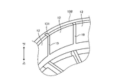
- stator
- machine according
- Prior art date
- Legal status (The legal status is an assumption and is not a legal conclusion. Google has not performed a legal analysis and makes no representation as to the accuracy of the status listed.)
- Ceased
Links
Images







Classifications
-
- H—ELECTRICITY
- H02—GENERATION; CONVERSION OR DISTRIBUTION OF ELECTRIC POWER
- H02K—DYNAMO-ELECTRIC MACHINES
- H02K5/00—Casings; Enclosures; Supports
- H02K5/04—Casings or enclosures characterised by the shape, form or construction thereof
- H02K5/16—Means for supporting bearings, e.g. insulating supports or means for fitting bearings in the bearing-shields
- H02K5/173—Means for supporting bearings, e.g. insulating supports or means for fitting bearings in the bearing-shields using bearings with rolling contact, e.g. ball bearings
Definitions
- This disclosure relates to electric work machines.
- the purpose of this disclosure is to reduce the size of the motor.
- a stator including a stator core, an insulator fixed to the stator core, a coil mounted on the insulator, a rotor cup at least partially arranged on the outer peripheral side of the stator, and a rotor.
- a rotor with a magnet fixed to the cup a stator base that supports the stator core, a rotor shaft that is at least partly located inside the stator base and rotates about a rotation axis, and an output unit driven by the rotor.
- a bearing that is located between the stator base and the rotor shaft to support the rotor shaft, and provides an electric working machine that overlaps at least a portion of the bearing and the stator core in the axial direction of the rotating shaft.
- a stator including a stator core, an insulator fixed to the stator core, a coil mounted on the insulator, a rotor cup at least partially arranged on the outer peripheral side of the stator, and a rotor.
- a rotor with a magnet fixed to the cup a stator base that supports the stator core, a rotor shaft that is at least partly located inside the stator base and rotates about a rotation axis, and an output unit driven by the rotor.
- a first bearing arranged between the stator base and the rotor shaft to support the first portion of the rotor shaft, and a second bearing arranged between the stator base and the rotor shaft to support the second portion of the rotor shaft.
- an electric working machine is provided.
- the motor is downsized.
- FIG. 1 is a diagram showing an electric working machine according to the first embodiment.
- FIG. 2 is a perspective view showing a motor according to the first embodiment.
- FIG. 3 is a perspective view showing a motor according to the first embodiment.
- FIG. 4 is a vertical sectional view showing a motor according to the first embodiment.
- FIG. 5 is an exploded perspective view showing the motor according to the first embodiment.
- FIG. 6 is a plan view of the motor according to the first embodiment as viewed from below.
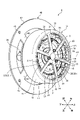
- FIG. 7 is a perspective view showing the motor according to the second embodiment.
- FIG. 8 is a perspective view showing the motor according to the second embodiment.
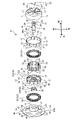
- FIG. 9 is an exploded perspective view showing the motor according to the second embodiment.
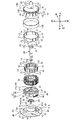
- FIG. 10 is an exploded perspective view showing the rotor according to the second embodiment.
- FIG. 10 is an exploded perspective view showing the rotor according to the second embodiment.
- FIG. 11 is a perspective view showing a part of a modified example of the rotor according to the second embodiment.
- FIG. 12 is a perspective view showing a part of a modified example of the rotor according to the second embodiment.
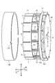
- FIG. 13 is a perspective view showing the rotor according to the third embodiment.
- FIG. 14 is an exploded perspective view showing the rotor according to the third embodiment.
- the electric work machine has a motor.
- the radial direction of the rotation shaft AX of the motor is appropriately referred to as a radial direction.
- the direction parallel to the rotation axis AX of the motor is appropriately referred to as an axial direction.
- the direction around the rotation axis AX of the motor is appropriately referred to as a circumferential direction or a rotation direction.
- the position close to or close to the rotation axis AX of the motor in the radial direction is appropriately referred to as the inside in the radial direction, and the position far from or separated from the rotation axis AX of the motor in the radial direction is appropriately referred to as the outside in the radial direction.
- the position on one side or the direction on one side in the axial direction is appropriately referred to as one side in the axial direction, and the position on the other side or the direction on the other side in the axial direction is appropriately referred to as the other side in the axial direction.
- the position on one side or the direction on one side in the circumferential direction is appropriately referred to as one side in the circumferential direction, and the position on the other side or the direction on the other side in the circumferential direction is appropriately referred to as the other side in the circumferential direction.
- FIG. 1 is a diagram showing an electric working machine 1 according to the present embodiment.
- the electric working machine 1 is a lawn mower which is a kind of gardening tool (Outdoor Power Equipment).
- the electric work machine 1 includes a housing 2, wheels 3, a motor 4, a cutting blade 5, a cutting box 6, a handle 7, and a battery mounting portion 8.
- the housing 2 accommodates the motor 4 and the cutting blade 5. Each of the wheel 3, the motor 4, and the cutting blade 5 is supported by the housing 2.
- Wheel 3 rotates in contact with the ground. By rotating the wheels 3, the electric work machine 1 can move on the ground. Four wheels 3 are provided.
- the motor 4 is a power source for the electric work machine 1.
- the motor 4 generates a rotational force that rotates the cutting blade 5.
- the motor 4 is arranged above the cutting blade 5.
- the cutting blade 5 is connected to the motor 4.
- the cutting blade 5 is an output unit of the electric working machine 1 driven by the motor 4.
- the cutting blade 5 rotates about the rotation axis AX of the motor 4 due to the rotational force generated by the motor 4.
- the cutting blade 5 faces the ground. With the wheels 3 in contact with the ground, the cutting blade 5 rotates to mow the grass growing on the ground.
- the lawn cut by the cutting blade 5 is housed in the cutting box 6.
- the handle 7 is held by the user of the electric work machine 1. The user can move the electric work machine 1 while holding the handle 7 by hand.
- the battery pack 9 is mounted on the battery mounting portion 8.
- the battery pack 9 is a power source for the electric work machine 1.
- the battery pack 9 is removable from the battery mounting portion 8.
- the battery pack 9 includes a secondary battery.
- the battery pack 9 includes a rechargeable lithium-ion battery.
- the battery pack 9 can supply electric power to the electric work machine 1 by being mounted on the battery mounting portion 8.
- the motor 4 is driven based on the drive current supplied from the battery pack 9.
- FIG. 2 and 3 are perspective views showing the motor 4 according to the present embodiment.
- FIG. 2 is a perspective view from the upper side.
- FIG. 3 is a perspective view from the lower side.
- FIG. 4 is a vertical sectional view showing the motor 4 according to the present embodiment. The vertical sectional view is a sectional view including the rotation axis AX and parallel to the rotation axis AX.
- FIG. 5 is an exploded perspective view showing the motor 4 according to the present embodiment.
- FIG. 6 is a plan view of the motor 4 according to the present embodiment as viewed from below.
- the motor 4 is an outer rotor type brushless motor.
- the motor 4 includes a rotor 10, a rotor shaft 20, a stator 30, a stator base 40, and a sensor substrate 50.
- the rotor 10 rotates with respect to the stator 30. At least a part of the rotor 10 is arranged on the outer peripheral side of the stator 30.
- the rotor shaft 20 is fixed to the rotor 10. At least a portion of the rotor shaft 20 is located inside the stator base 40.
- the rotor 10 and the rotor shaft 20 rotate about the rotation shaft AX.
- the stator base 40 supports the stator 30.
- the stator base 40 is fixed to the stator core 31.
- the cutting blade 5 is connected to the rotor shaft 20. The cutting blade 5 is driven by the rotor 10.
- the sensor board 50 supports a magnetic sensor that detects the rotation of the rotor 10.
- the rotation shaft AX of the motor 4 extends in the vertical direction.
- the axial direction and the vertical direction are parallel.
- one side in the axial direction is appropriately referred to as an upper side, and the other side in the axial direction is appropriately referred to as a lower side.
- the rotor 10 has a rotor cup 11 and a magnet 12.
- the rotor cup 11 is made of a metal containing iron as a main component.
- the magnet 12 is a permanent magnet. At least a part of the rotor cup 11 is arranged on the outer peripheral side of the stator 30.
- the magnet 12 is fixed to the rotor cup 11.
- the rotor cup 11 has a rotor yoke 13, a rotor plate 14, and a radiating rib 15.
- the rotor yoke 13 has a cylindrical shape.
- the rotor yoke 13 is arranged so as to surround the stator 30.
- the rotor yoke 13 is arranged around the rotation axis AX.
- the central axis of the rotor yoke 13 and the rotation axis AX coincide with each other.
- the rotor plate 14 is annular.
- the rotor plate 14 is arranged around the rotation axis AX.
- the central axis of the rotor plate 14 and the rotation axis AX coincide with each other.
- At least a portion of the rotor plate 14 faces the shaft end face 21 of the rotor shaft 20.
- the shaft end surface 21 faces upward.
- the radial rib 15 connects the rotor yoke 13 and the rotor plate 14.
- the radial rib 15 extends radially outward from the rotor plate 14.
- a plurality of radial ribs 15 are provided at intervals in the circumferential direction.
- the rotor yoke 13, the rotor plate 14, and the radiating rib 15 are integrated.
- the magnet 12 is fixed to the rotor yoke 13.
- a plurality of magnets 12 are arranged in the circumferential direction.
- 14 magnets 12 are arranged in the circumferential direction.
- the north pole, the magnet 12, and the south pole magnet 12 are alternately arranged in the circumferential direction.
- the magnet 12 is arranged inside the rotor yoke 13.
- the magnet 12 is fixed to the inner surface of the rotor yoke 13 with, for example, an adhesive.
- the rotor shaft 20 extends in the axial direction.
- the central axis of the rotor shaft 20 and the rotary axis AX coincide with each other.
- the rotor shaft 20 is fixed to the rotor 10 so that the central axis of the rotor shaft 20 and the central axis of the rotor yoke 13 coincide with each other.
- the rotor shaft 20 has a shaft protrusion 22 that projects upward from the shaft end surface 21.
- the rotor plate 14 has a shaft opening 16 in which the shaft protrusion 22 is arranged. By arranging the shaft convex portion 22 in the shaft opening 16, the rotor 10 and the rotor shaft 20 are positioned in the radial direction.
- the rotor 10 and the rotor shaft 20 are positioned in the axial direction by the contact between the shaft end surface 21 around the shaft convex portion 22 and the lower surface of the rotor plate 14.
- the rotor shaft 20 and the rotor plate 14 of the rotor 10 are fixed by the rotor screw 23.
- a screw hole 24 is formed in the shaft end surface 21.
- a screw opening 17 is formed in the rotor plate 14.
- the rotor screw 23 is inserted into the screw hole 24 through the screw opening 17 with the shaft convex portion 22 arranged in the shaft opening 16.
- the rotor 10 and the rotor shaft 20 are fixed by the rotor screw 23 by connecting the thread provided in the rotor screw 23 and the thread groove provided in the screw hole 24.
- the rotor 10 and the rotor shaft 20 are fixed by three rotor screws 23.
- the stator 30 has a stator core 31, an insulator 32, and a coil 33.
- the stator core 31 is made of a metal containing iron as a main component.
- the stator core 31 has a stator yoke 34 and teeth 35.
- the stator yoke 34 has a cylindrical shape.
- the stator yoke 34 is arranged around the rotation axis AX.
- the central axis of the stator yoke 34 and the rotation axis AX coincide with each other.
- the teeth 35 project radially outward from the outer surface of the stator yoke 34.
- a plurality of teeth 35 are provided at intervals in the circumferential direction. In this embodiment, 12 teeth 35 are provided.
- a slot 36 is formed between the teeth 35 adjacent to each other.
- the insulator 32 is made of synthetic resin.
- the insulator 32 is fixed to the stator core 31.
- the insulator 32 covers at least a part of the surface of the stator core 31.
- the insulator 32 covers at least a part of the end face of the stator yoke 34 facing in the axial direction.
- the end surface of the stator yoke 34 includes an upper end surface facing upward and a lower end surface facing downward. Further, the insulator 32 covers at least a part of the outer surface of the stator yoke 34 facing outward in the radial direction. Further, the insulator 32 covers at least a part of the surface of the teeth 35.
- the insulator 32 includes an upper insulator 321 fixed to the upper part of the stator core 31 and a lower insulator 322 fixed to the lower part of the stator core 31.
- the upper insulator 321 is attached to the stator core 31 from the upper side of the stator core 31.
- the lower insulator 322 is attached to the stator core 31 from the lower side of the stator core 31.
- the coil 33 is mounted on the insulator 32.
- the coil 33 is wound around the teeth 35 via the insulator 32.
- the surface of the teeth 35 around which the coil 33 is wound is covered with the insulator 32.
- the outer surface of the teeth 35 facing radially outward is not covered by the insulator 32.
- the stator core 31 and the coil 33 are insulated by the insulator 32.
- a plurality of coils 33 are provided. In this embodiment, 12 coils 33 are arranged in the circumferential direction.
- the sensor board 50 is fixed to the insulator 32.
- the sensor board 50 supports a magnetic sensor that detects the rotation of the rotor 10.
- the sensor substrate 50 is fixed to the insulator 32 so that the magnet 12 and the magnetic sensor face each other.
- the sensor substrate 50 is arranged radially outside the coil 33.
- the stator base 40 supports the stator core 31.
- the stator base 40 is made of aluminum.
- the stator base 40 has a pipe portion 41, a foot portion 42, and a connecting rib portion 43.
- the pipe portion 41 is substantially cylindrical.
- the pipe portion 41 is arranged around the rotation axis AX.
- the central axis of the pipe portion 41 and the rotation axis AX coincide with each other.
- the pipe portion 41 is arranged inside the stator core 31.
- the central axis of the pipe portion 41 and the central axis of the stator yoke 34 coincide with each other.
- the pipe portion 41 includes a small diameter portion 41A and a large diameter portion 41B arranged below the small diameter portion 41A.
- Each of the small diameter portion 41A and the large diameter portion 41B has a cylindrical shape.
- the outer diameter of the large diameter portion 41B is larger than the outer diameter of the small diameter portion 41A.
- the central axis of the pipe portion 41 and the rotation axis AX coincide with each other.
- the stator core 31 is arranged around the small diameter portion 41A.
- the small diameter portion 41A is arranged inside the stator core 31.
- the large diameter portion 41B is arranged outside the stator core 31.
- the stator core 31 is fixed to the pipe portion 41.
- the stator base 40 is fixed to the stator 30 so that the central axis of the pipe portion 41 and the central axis of the stator yoke 34 coincide with each other.
- the pipe portion 41 supports the rotor shaft 20 via the bearing 25.
- the rotor shaft 20 is arranged inside the pipe portion 41.
- the rotor shaft 20 is supported by the pipe portion 41 via the bearing 25.
- the bearing 25 is arranged between the stator base 40 and the rotor shaft 20.
- the bearing 25 is arranged between the inner surface of the pipe portion 41 and the outer surface of the rotor shaft 20.
- the bearing 25 rotatably supports the rotor shaft 20.
- the bearing 25 includes an upper bearing 251 (first bearing) and a lower bearing 252 (second bearing) arranged below the upper bearing 251.
- the upper bearing 251 supports the first portion of the rotor shaft 20.
- the lower bearing 252 supports the second portion of the rotor shaft 20 below the first portion.
- Each of the upper bearing 251 and the lower bearing 252 is arranged between the pipe portion 41 of the stator base 40 and the rotor shaft 20.
- the bearing 25 and at least a part of the stator core 31 overlap. That is, in the axial direction, the position of the bearing 25 and the position of at least a part of the stator core 31 coincide with each other.
- the bearing 25 includes an upper bearing 251 and a lower bearing 252. In the axial direction, one or both of the upper bearing 251 and the lower bearing 252 overlap with at least a part of the stator core 31. As shown in FIG. 4, in the present embodiment, the upper bearing 251 and at least a part of the stator core 31 overlap in the axial direction. In the axial direction, the lower bearing 252 and at least a part of the stator core 31 may overlap, or both the upper bearing 251 and the lower bearing 252 overlap with at least a part of the stator core 31. May be good.
- the upper bearing 251 has an upper end surface 253 (first end surface) facing upward and a lower end surface 254 (second end surface) facing downward.
- the rotor shaft 20 has a first support surface 28 that supports the upper end surface 253.
- the stator base 40 has a second support surface 413 that supports the lower end surface 254, the first support surface 28 facing downward.
- the second support surface 413 faces upward.
- a step 29 is provided on at least a part of the outer surface of the rotor shaft 20.
- the first support surface 28 includes the lower surface of the step portion 29 facing downward.
- the first support surface 28 contacts a part of the upper end surface 253 on the inner side in the radial direction.
- a step portion 414 is provided on at least a part of the inner surface of the pipe portion 41.
- the second support surface 413 includes the upper surface of the step portion 414 facing upward.
- the second support surface 413 contacts a part of the lower end surface 254 on the outer side in the radial direction.
- the inner surface of the upper bearing 251 facing inward in the radial direction contacts the outer surface of the rotor shaft 20.
- the outer surface of the upper bearing 251 facing outward in the radial direction contacts the inner surface of the pipe portion 41.
- the upper bearing 251 is sandwiched between the first support surface 28 and the second support surface 413 in the axial direction.
- the upper bearing 251 is sandwiched between the outer surface of the rotor shaft 20 and the inner surface of the pipe portion 41 in the radial direction. As a result, the upper bearing 251 and the rotor shaft 20 and the stator base 40 are positioned.
- the lower bearing 252 has an upper end surface 255 (third end surface) facing upward and a lower end surface 256 (fourth end surface) facing downward.
- the stator base 40 has a third support surface 415 that supports the upper end surface 255, the third support surface 415 facing downward.
- a step portion 416 is provided on at least a part of the inner surface of the pipe portion 41.
- the third support surface 415 includes the lower surface of the step portion 416 facing downward.
- the third support surface 415 contacts a part of the upper end surface 255 on the outer side in the radial direction.
- a circlip 27 that supports the lower end surface 256 is attached to the rotor shaft 20.
- a groove 200 is formed on a part of the outer surface of the rotor shaft 20.
- At least a portion of the circlip 27 is located inside the groove 200.
- the circlip 27 contacts a part of the lower end surface 256 on the inner side in the radial direction.
- the inner surface of the lower bearing 252 facing inward in the radial direction contacts the outer surface of the rotor shaft 20.
- the outer surface of the lower bearing 252 facing outward in the radial direction contacts the inner surface of the pipe portion 41.
- the lower bearing 252 is sandwiched between the third support surface 415 and the circlip 27 in the axial direction.
- the lower bearing 252 is sandwiched between the outer surface of the rotor shaft 20 and the inner surface of the pipe portion 41 in the radial direction.
- the lower bearing 252 is fixed to the pipe portion 41 by the bearing fixing screw 26.
- a screw boss 48 is provided at the lower end of the pipe portion 41.
- the bearing fixing screw 26 is inserted into a screw hole provided in the screw boss 48.
- the head of the bearing fixing screw 26 becomes the lower end surface of the lower bearing 252.
- the lower bearing 252 is fixed to the pipe portion 41 by the contact between the head of the bearing fixing screw 26 and the lower bearing 252.
- the foot portion 42 is arranged outside the stator core 31.
- the foot portion 42 is annular.
- the foot portion 42 has a plate shape.
- the central axis of the pipe portion 41 and the central axis of the foot portion 42 coincide with each other.
- the foot portion 42 is fixed to the fixing target.
- a fixing target a housing 2 accommodating a motor 4 is exemplified. By fixing the foot portion 42 to the fixing target, the motor 4 is fixed to the fixing target.
- the inner diameter of the foot portion 42 is larger than the outer diameter of the pipe portion 41.
- the foot portion 42 is provided with a screw opening 45.
- a screw (not shown) is arranged in the screw opening 45.
- the foot portion 42 and the fixing target are fixed by connecting the screw arranged in the screw opening 45 to the screw hole provided in the fixing target.
- the connecting rib portion 43 connects the pipe portion 41 and the foot portion 42.
- the connecting rib portion 43 extends radially outward from the outer surface of the pipe portion 41.
- a plurality of connecting rib portions 43 are provided at intervals in the circumferential direction. In this embodiment, four connecting rib portions 43 are provided.
- the connecting rib portion 43 connects the large diameter portion 41B of the pipe portion 41 and the foot portion 42.
- the radial inner end of the connecting rib portion 43 is fixed to the outer surface of the large diameter portion 41B.
- the radial outer end of the connecting rib portion 43 is fixed to the inner surface of the foot portion 42.
- the connecting rib portion 43 connects the pipe portion 41 and the foot portion 42 so that the central axis of the pipe portion 41 and the central axis of the foot portion 42 coincide with each other.
- the stator 30 has a stator screw 37 that fixes the stator base 40 and the stator core 31.
- a screw opening 38 is formed in the stator core 31.
- the screw opening 38 of the stator core 31 is formed so as to penetrate the upper end surface and the lower end surface of the stator yoke 34.
- a screw hole 47 is formed on the end surface of the stator base 40 facing upward of the large diameter portion 41B.
- the stator screw 37 is inserted into the screw opening 38 of the stator core 31 from the upper side of the stator core 31.
- the stator screw 37 is inserted into the screw hole 47 of the stator base 40 through the screw opening 38 of the stator core 31.
- the stator core 31 and the stator base 40 are fixed by the stator screw 37 by connecting the thread provided in the stator screw 37 and the thread groove provided in the screw hole 47.
- the stator core 31 and the stator base 40 are fixed by three stator screws 37.
- the motor 4 is a three-phase brushless motor.
- Each of the twelve coils 33 is assigned to any one of the U (UV) phase, the V (VW) phase, and the W (WU) phase.
- the drive current supplied from the battery pack 9 to the motor 4 includes a U-phase drive current, a V-phase drive current, and a W-phase drive current.
- the drive current from the battery pack 9 is supplied to the coil 33 via a bus bar (not shown).
- a rotating magnetic field is generated in the stator 30 by supplying a drive current from the battery pack 9 to the coil 33. When a rotating magnetic field is generated in the stator 30, the rotor 10 and the rotor shaft 20 rotate around the rotating shaft AX.
- the bearing 25 and at least a part of the stator core 31 overlap in the axial direction. As a result, the increase in the size of the motor 4 in the axial direction is suppressed.
- both the upper bearing 251 and the lower bearing 252 are arranged between the pipe portion 41 of the stator base 40 and the rotor shaft 20. As a result, the increase in the size of the motor 4 in the axial direction is suppressed.
- the upper end surface 253 of the upper bearing 251 comes into contact with the first support surface 28 of the rotor shaft 20.
- the lower end surface 254 of the upper bearing 251 contacts the second support surface 413 of the stator base 40.
- the upper bearing 251 is inserted into the inside of the pipe portion 41 from the upper side of the pipe portion 41 together with the rotor shaft 20 in a state of being in contact with the first support surface 28, whereby the first support surface 28 and the second support are supported. It is sandwiched between the surface 413 and the surface 413. As a result, the upper bearing 251 and the rotor shaft 20 and the stator base 40 are positioned.
- the upper end surface 255 of the lower bearing 252 contacts the third support surface 415 of the stator base 40.
- the lower bearing 252 can come into contact with the third support surface 415 by being inserted into the inside of the pipe portion 41 from the lower side of the pipe portion 41.
- the circlip 27 is arranged in the groove 200, so that the lower bearing 252 is sandwiched between the third support surface 415 and the circlip 27 in the axial direction. Is done.
- the lower bearing 252, the rotor shaft 20, and the stator base 40 are positioned.
- a rotor screw 23 for fixing the rotor shaft 20 and the rotor plate 14 is provided.
- the rotor shaft 20 and the rotor 10 are easily fixed by the rotor screw 23.
- the shaft convex portion 22 of the rotor shaft 20 is arranged in the shaft opening 16 of the rotor plate 14. As a result, the rotor 10 and the rotor shaft 20 are positioned.
- the rotor yoke 13, the rotor plate 14, and the radiating rib 15 are integrated. As a result, changes in the relative positions of the magnet 12 fixed to the rotor yoke 13 and the rotor yoke 13 and the rotor plate 14 and the rotor shaft 20 fixed to the rotor plate 14 are suppressed.
- FIG. 7 and 8 are perspective views showing the motor 4 according to the present embodiment.
- FIG. 7 is a perspective view from the upper side.
- FIG. 8 is a perspective view from the lower side.
- FIG. 9 is an exploded perspective view showing the motor 4 according to the present embodiment.
- the insulator 32 includes the upper insulator 321 and the lower insulator 322.
- the insulator 32 is integrally molded with the stator core 31.
- the insulator 32 is fixed to the stator core by, for example, insert molding.
- the rotor cup 11 includes a cylindrical rotor yoke 13B, a rotor plate 14B at least partially facing the shaft end face 21, and a rotor ring 18 fixed to the rotor plate 14B via a connecting rib 180. It has a columnar rib 19 extending axially from the rotor ring 18.
- the rotor yoke 13B is formed, for example, by drawing.
- the rotor plate 14B, the connecting rib 180, the rotor ring 18, and the columnar rib 19 are integrated.
- the rotor yoke 13B and the rotor plate 14B are separate bodies.
- the columnar rib 19 projects downward from the rotor ring 18.
- a plurality of columnar ribs 19 are provided at intervals in the circumferential direction. In this embodiment, 14 columnar ribs 19 are provided.
- FIG. 10 is an exploded perspective view showing the rotor 10 according to the present embodiment.
- the magnet 12 is arranged inside the rotor yoke 13B.
- the columnar rib 19 is inserted inside the rotor yoke 13B.
- the columnar rib 19 comes into contact with the magnet 12.
- the columnar ribs 19 are arranged between magnets 12 that are adjacent to each other in the circumferential direction.
- the magnet 12 is positioned by the columnar rib 19.
- the rotor yoke 13B and the rotor ring 18 are connected.
- the rotor ring 18 has a ring large diameter portion 18A that contacts the upper end surface of the rotor yoke 13B, and a ring small diameter portion 18B that is arranged inside the rotor yoke 13B.
- the ring small diameter portion 18B fits inside the rotor yoke 13B in a state where the upper end surface of the rotor yoke 13B is in contact with the ring large diameter portion 18A.
- the outer surface of the ring small diameter portion 18B contacts the inner surface of the rotor yoke 13B.
- the rotor yoke 13B and the rotor ring 18 are positioned in the axial direction by the contact between the upper end surface of the rotor yoke 13B and the ring large diameter portion 18A.
- the ring small diameter portion 18B fits inside the rotor yoke 13B, and the outer surface of the ring small diameter portion 18B and the inner surface of the rotor yoke 13B come into contact with each other, so that the rotor yoke 13B and the rotor ring 18 are positioned in the radial direction.
- the rotor ring 18 has a ring convex portion 181 protruding downward from the lower end surface of the ring large diameter portion 18A.
- the rotor yoke 13B has a ring recess 130 in which the ring protrusion 181 is arranged. By arranging the ring protrusion 181 on the rotor yoke 13B, the rotor yoke 13B and the rotor ring 18 are positioned in the circumferential direction.
- One ring convex portion 181 is provided.
- One ring recess 130 is provided. In the circumferential direction, the boundary between the magnets 12 adjacent to each other and at least a part of the ring recess 130 overlap. That is, in the circumferential direction, the position of one columnar rib 19 and the position of the ring convex portion 181 coincide with each other.
- the rotor yoke 13B and the rotor plate 14B are separate bodies.
- the rotor yoke 13B can be easily manufactured, for example, by drawing.
- the rotor ring 18 is fixed to the rotor plate 14B via the connecting rib 180.
- a columnar rib 19 extends axially from the rotor ring 18. The columnar ribs 19 allow the magnet 12 to be easily positioned. This improves the productivity of the motor 4.
- the rotor ring 18 has a ring large diameter portion 18A that contacts the upper end surface of the rotor yoke 13B and a ring small diameter portion 18B that is arranged inside the rotor yoke 13B.
- the rotor yoke 13B and the rotor ring 18 are positioned in the axial direction by the contact between the upper end surface of the rotor yoke 13B and the ring large diameter portion 18A.
- the ring small diameter portion 18B inside the rotor yoke 13B, the rotor yoke 13B and the rotor ring 18 are positioned in the radial direction.
- the rotor ring 18 has a ring convex portion 181 protruding downward from the lower end surface of the ring large diameter portion 18A.
- the rotor yoke 13B has a ring recess 130 in which the ring protrusion 181 is arranged.
- the ring convex portion 181 is arranged in the ring concave portion 130, the rotor yoke 13B and the rotor ring 18 are positioned. Further, since the ring convex portion 181 projects downward from the lower end surface of the ring large diameter portion 18A, it is possible to prevent the rotor ring 18 from becoming larger in the radial direction.
- the boundary between the magnets 12 adjacent to each other and at least a part of the ring recess 130 overlap. That is, the ring concave portion 130 and the ring convex portion 181 are arranged at positions in the rotor 10 where the passage of magnetic force lines is small. As a result, deterioration of the performance of the motor 4 is suppressed.
- FIG. 11 is a perspective view showing a part of a modified example of the rotor 10 according to the present embodiment.
- the groove 131 may be provided on the inner surface of the rotor yoke 13B.
- the groove 131 is provided on the inner surface of the rotor yoke 13B so as to extend in the axial direction.
- FIG. 12 is a perspective view showing a part of a modified example of the rotor 10 according to the present embodiment.
- a protruding rib 132 may be provided on the inner surface of the rotor yoke 13B.
- the protruding rib 132 projects radially inward from the inner surface of the rotor yoke 13B.
- the magnet 12 is arranged inside the rotor yoke 13B.
- the protruding ribs 132 are arranged between magnets 12 adjacent to each other. The protruding rib 132 positions the rotor yoke 13B and the magnet 12 in the circumferential direction.
- the protruding ribs 132 and the columnar ribs 19 may be arranged alternately in the circumferential direction. That is, the protruding ribs 132 may be arranged between the columnar ribs 19 that are adjacent to each other in the circumferential direction. As a result, the rotor yoke 13B, the rotor ring 18, and the magnet 12 are positioned in the circumferential direction.
- FIG. 13 is a perspective view showing the rotor 10 according to the present embodiment.
- FIG. 14 is an exploded perspective view showing the rotor 10 according to the present embodiment.
- the rotor yoke 13B has a first yoke portion 1301, a second yoke portion 1302, a third yoke portion 1303, and a fourth yoke portion 1304.
- Each of the first yoke portion 1301, the second yoke portion 1302, the third yoke portion 1303, and the fourth yoke portion 1304 is ring-shaped.
- the second yoke portion 1302 is connected to the first yoke portion 1301.
- the third yoke portion 1303 is connected to the second yoke portion 1302.
- the fourth yoke portion 1304 is connected to the third yoke portion 1303.
- the first yoke portion 1301 has a yoke large diameter portion 13C that contacts the upper end surface of the second yoke portion 1302 and a yoke small diameter portion 13D that is arranged inside the second yoke portion 1302.
- the second yoke portion 1302 has a yoke large diameter portion 13C that contacts the upper end surface of the third yoke portion 1303, and a yoke small diameter portion 13D that is arranged inside the third yoke portion 1303.
- the third yoke portion 1303 has a yoke large diameter portion 13C that contacts the upper end surface of the fourth yoke portion 1304, and a yoke small diameter portion 13D that is arranged inside the fourth yoke portion 1304.
- the first yoke portion 1301 has a yoke convex portion 133 that projects downward from the lower surface of the yoke large diameter portion 13C of the first yoke portion 1301.
- the second yoke portion 1302 has a yoke recess 134 in which the yoke convex portion 133 of the first yoke portion 1301 is arranged.
- the yoke recess 134 of the second yoke portion 1302 is provided on the upper end surface of the second yoke portion 1302.
- the second yoke portion 1302 has a yoke convex portion 133 projecting downward from the lower surface of the yoke large diameter portion 13C of the second yoke portion 1302.
- the third yoke portion 1303 has a yoke recess 134 in which the yoke convex portion 133 of the second yoke portion 1302 is arranged.
- the third yoke portion 1303 has a yoke convex portion 133 that projects downward from the lower surface of the yoke large diameter portion 13C of the third yoke portion 1303.
- the fourth yoke portion 1304 has a yoke recess 134 in which the yoke convex portion 133 of the third yoke portion 1303 is arranged.
- the first yoke portion 1301 and the second yoke portion 1302 are positioned in the axial direction by the contact between the yoke large diameter portion 13C of the first yoke portion 1301 and the upper end surface of the second yoke portion 1302.
- the yoke small diameter portion 13D of the first yoke portion 1301 is arranged inside the second yoke portion 1302, and the inside of the second yoke portion 1302 and the outer surface of the yoke small diameter portion 13D come into contact with each other, so that the first yoke portion in the radial direction is formed.
- the 1301 and the second yoke portion 1302 are positioned.
- the first yoke portion 1301 and the second yoke portion 1302 are positioned in the circumferential direction.
- the second yoke portion 1302 and the third yoke portion 1303 are positioned, and the third yoke portion 1303 and the fourth yoke portion 1304 are positioned.
- the rotor yoke 13B may be composed of a plurality of yoke portions (1301, 1302, 1303, 1304). Each of the plurality of yoke portions (1301, 1302, 1303, 1304) is manufactured, for example, by drawing. Since the rotor yoke 13B is composed of a plurality of yoke portions (1301, 1302, 1303, 1304), the loss due to the eddy current is reduced.
- the first yoke portion 1301 has a yoke large diameter portion 13C that contacts the upper end surface of the second yoke portion 1302 and a yoke small diameter portion 13D that is arranged inside the second yoke portion 1302.
- the first yoke portion 1301 and the second yoke portion 1302 are positioned in the axial direction by the contact between the yoke large diameter portion 13C of the first yoke portion 1301 and the upper end surface of the second yoke portion 1302.
- the yoke small diameter portion 13D of the first yoke portion 1301 is arranged inside the second yoke portion 1302, and the inner surface of the second yoke portion 1302 and the outer surface of the yoke small diameter portion 13D of the first yoke portion 1301 come into contact with each other to form a diameter.
- the first yoke portion 1301 and the second yoke portion 1302 are positioned in the direction.
- the first yoke portion 1301 has a yoke convex portion 133 projecting axially from the yoke large diameter portion 13C
- the second yoke portion 1302 has a yoke concave portion 134 in which the yoke convex portion 133 is arranged.
- the electric working machine 1 is a lawn mower which is a kind of gardening tool.
- gardening tools are not limited to lawnmowers. Examples of gardening tools include hedge trimmers, chainsaws, mowers, and blowers. Further, the electric work machine 1 may be an electric tool. Examples of power tools include driver drills, vibration driver drills, angle drills, impact drivers, grinders, hammers, hammer drills, circular saws, and reciprocating saws.
- a battery pack mounted on the battery mounting portion is used as a power source for the electric work machine.
- a commercial power source (AC power source) may be used as a power source for the electric work machine.
- Third support surface, 416 ... Step portion, 1301 ... First yoke portion, 1302 ... Second yoke 1303 ... 3rd yoke part, 1304 ... 4th yoke part, AX ... Rotating shaft.
Landscapes
- Engineering & Computer Science (AREA)
- Power Engineering (AREA)
- Motor Or Generator Frames (AREA)
- Permanent Field Magnets Of Synchronous Machinery (AREA)
Applications Claiming Priority (2)
| Application Number | Priority Date | Filing Date | Title |
|---|---|---|---|
| JP2020203874A JP7695071B2 (ja) | 2020-12-09 | 2020-12-09 | 電動チェーンソー |
| JP2020-203874 | 2020-12-09 |
Publications (1)
| Publication Number | Publication Date |
|---|---|
| WO2022123925A1 true WO2022123925A1 (ja) | 2022-06-16 |
Family
ID=81973629
Family Applications (1)
| Application Number | Title | Priority Date | Filing Date |
|---|---|---|---|
| PCT/JP2021/038998 Ceased WO2022123925A1 (ja) | 2020-12-09 | 2021-10-21 | 電動作業機 |
Country Status (2)
| Country | Link |
|---|---|
| JP (1) | JP7695071B2 (https=) |
| WO (1) | WO2022123925A1 (https=) |
Citations (7)
| Publication number | Priority date | Publication date | Assignee | Title |
|---|---|---|---|---|
| WO2002052698A1 (fr) * | 2000-12-22 | 2002-07-04 | Mitsuba Corporation | Dispositif de support d'aimants pour rotor |
| JP2010178493A (ja) * | 2009-01-29 | 2010-08-12 | Mitsuba Corp | アウターロータ型ブラシレスモータ |
| JP2018143043A (ja) * | 2017-02-28 | 2018-09-13 | 日本電産株式会社 | モータ |
| JP2019054615A (ja) * | 2017-09-14 | 2019-04-04 | 日本電産株式会社 | モータ |
| WO2020067245A1 (ja) * | 2018-09-28 | 2020-04-02 | 日本電産株式会社 | ロータ、ロータの製造方法、モータ |
| JP2020088909A (ja) * | 2018-11-15 | 2020-06-04 | 株式会社三井ハイテック | 鉄心製品及び鉄心製品の製造方法 |
| JP2020145766A (ja) * | 2017-05-23 | 2020-09-10 | 澤藤電機株式会社 | アウターロータ型電動機におけるロータ構造 |
Family Cites Families (5)
| Publication number | Priority date | Publication date | Assignee | Title |
|---|---|---|---|---|
| JP2000184641A (ja) | 1998-12-15 | 2000-06-30 | Shinano Kenshi Co Ltd | アウターロータ型回転子とアウターロータ型モータとアウターロータ型モータのバックヨークの製造方法 |
| JP2003324866A (ja) | 2002-04-30 | 2003-11-14 | Fujitsu General Ltd | 永久磁石電動機 |
| JP6167434B2 (ja) | 2013-09-30 | 2017-07-26 | ミネベアミツミ株式会社 | ブラシレスモータ及びそのモータを用いた送風機 |
| JP7000650B2 (ja) | 2017-09-29 | 2022-01-19 | 日本電産サーボ株式会社 | モータ |
| JP7051568B2 (ja) | 2018-05-08 | 2022-04-11 | 株式会社マキタ | 電動作業機 |
-
2020
- 2020-12-09 JP JP2020203874A patent/JP7695071B2/ja active Active
-
2021
- 2021-10-21 WO PCT/JP2021/038998 patent/WO2022123925A1/ja not_active Ceased
Patent Citations (7)
| Publication number | Priority date | Publication date | Assignee | Title |
|---|---|---|---|---|
| WO2002052698A1 (fr) * | 2000-12-22 | 2002-07-04 | Mitsuba Corporation | Dispositif de support d'aimants pour rotor |
| JP2010178493A (ja) * | 2009-01-29 | 2010-08-12 | Mitsuba Corp | アウターロータ型ブラシレスモータ |
| JP2018143043A (ja) * | 2017-02-28 | 2018-09-13 | 日本電産株式会社 | モータ |
| JP2020145766A (ja) * | 2017-05-23 | 2020-09-10 | 澤藤電機株式会社 | アウターロータ型電動機におけるロータ構造 |
| JP2019054615A (ja) * | 2017-09-14 | 2019-04-04 | 日本電産株式会社 | モータ |
| WO2020067245A1 (ja) * | 2018-09-28 | 2020-04-02 | 日本電産株式会社 | ロータ、ロータの製造方法、モータ |
| JP2020088909A (ja) * | 2018-11-15 | 2020-06-04 | 株式会社三井ハイテック | 鉄心製品及び鉄心製品の製造方法 |
Also Published As
| Publication number | Publication date |
|---|---|
| JP7695071B2 (ja) | 2025-06-18 |
| JP2022091205A (ja) | 2022-06-21 |
Similar Documents
| Publication | Publication Date | Title |
|---|---|---|
| US11646626B2 (en) | Brushless motor for a power tool | |
| US11863047B2 (en) | Electric work machine | |
| JP7393895B2 (ja) | 電動作業機 | |
| JP7519827B2 (ja) | 電動作業機 | |
| JP7716245B2 (ja) | 電動作業機 | |
| JP2023005814A (ja) | 電動作業機 | |
| JP7652649B2 (ja) | 電動作業機 | |
| US20220416598A1 (en) | Electric work machine | |
| US20250158499A1 (en) | Electric work machine and production method for electric work machine | |
| WO2022123926A1 (ja) | 電動作業機 | |
| US20230216359A1 (en) | Electric work machine | |
| US20230198342A1 (en) | Electric work machine | |
| JP2020124081A (ja) | 電動作業機 | |
| JP7695071B2 (ja) | 電動チェーンソー | |
| WO2022123927A1 (ja) | 電動作業機 | |
| JP7242214B2 (ja) | 電動作業機 | |
| JP7313924B2 (ja) | モータ及び電動作業機 | |
| US12155291B2 (en) | Power tool | |
| JP2020102959A (ja) | 電動作業機及び電動作業機用モータにおけるステータへのコイルの形成方法 | |
| JP2026006968A (ja) | 電動作業機 | |
| JP2021035122A (ja) | 電動作業機 | |
| WO2020137039A1 (ja) | 電動工具用の分布巻きモータ、電動工具及び芝刈り機 | |
| JP2020061829A (ja) | 電動作業機 |
Legal Events
| Date | Code | Title | Description |
|---|---|---|---|
| 121 | Ep: the epo has been informed by wipo that ep was designated in this application |
Ref document number: 21903029 Country of ref document: EP Kind code of ref document: A1 |
|
| NENP | Non-entry into the national phase |
Ref country code: DE |
|
| 122 | Ep: pct application non-entry in european phase |
Ref document number: 21903029 Country of ref document: EP Kind code of ref document: A1 |