WO2022123925A1 - Electric work machine - Google Patents
Electric work machine Download PDFInfo
- Publication number
- WO2022123925A1 WO2022123925A1 PCT/JP2021/038998 JP2021038998W WO2022123925A1 WO 2022123925 A1 WO2022123925 A1 WO 2022123925A1 JP 2021038998 W JP2021038998 W JP 2021038998W WO 2022123925 A1 WO2022123925 A1 WO 2022123925A1
- Authority
- WO
- WIPO (PCT)
- Prior art keywords
- rotor
- yoke
- shaft
- stator
- machine according
- Prior art date
Links
- 239000012212 insulator Substances 0.000 claims abstract description 39
- 230000002093 peripheral effect Effects 0.000 claims description 6
- XEEYBQQBJWHFJM-UHFFFAOYSA-N Iron Chemical compound [Fe] XEEYBQQBJWHFJM-UHFFFAOYSA-N 0.000 description 4
- 238000010413 gardening Methods 0.000 description 4
- 239000000758 substrate Substances 0.000 description 3
- 238000010586 diagram Methods 0.000 description 2
- 229910052742 iron Inorganic materials 0.000 description 2
- 229910052751 metal Inorganic materials 0.000 description 2
- 239000002184 metal Substances 0.000 description 2
- 244000025254 Cannabis sativa Species 0.000 description 1
- HBBGRARXTFLTSG-UHFFFAOYSA-N Lithium ion Chemical compound [Li+] HBBGRARXTFLTSG-UHFFFAOYSA-N 0.000 description 1
- 239000000853 adhesive Substances 0.000 description 1
- 230000001070 adhesive effect Effects 0.000 description 1
- 229910052782 aluminium Inorganic materials 0.000 description 1
- XAGFODPZIPBFFR-UHFFFAOYSA-N aluminium Chemical compound [Al] XAGFODPZIPBFFR-UHFFFAOYSA-N 0.000 description 1
- 230000006866 deterioration Effects 0.000 description 1
- 229910001416 lithium ion Inorganic materials 0.000 description 1
- 238000000034 method Methods 0.000 description 1
- 238000000465 moulding Methods 0.000 description 1
- 229920003002 synthetic resin Polymers 0.000 description 1
- 239000000057 synthetic resin Substances 0.000 description 1
Images


Classifications
-
- H—ELECTRICITY
- H02—GENERATION; CONVERSION OR DISTRIBUTION OF ELECTRIC POWER
- H02K—DYNAMO-ELECTRIC MACHINES
- H02K5/00—Casings; Enclosures; Supports
- H02K5/04—Casings or enclosures characterised by the shape, form or construction thereof
- H02K5/16—Means for supporting bearings, e.g. insulating supports or means for fitting bearings in the bearing-shields
- H02K5/173—Means for supporting bearings, e.g. insulating supports or means for fitting bearings in the bearing-shields using bearings with rolling contact, e.g. ball bearings
Definitions
- This disclosure relates to electric work machines.
- the purpose of this disclosure is to reduce the size of the motor.
- a stator including a stator core, an insulator fixed to the stator core, a coil mounted on the insulator, a rotor cup at least partially arranged on the outer peripheral side of the stator, and a rotor.
- a rotor with a magnet fixed to the cup a stator base that supports the stator core, a rotor shaft that is at least partly located inside the stator base and rotates about a rotation axis, and an output unit driven by the rotor.
- a bearing that is located between the stator base and the rotor shaft to support the rotor shaft, and provides an electric working machine that overlaps at least a portion of the bearing and the stator core in the axial direction of the rotating shaft.
- a stator including a stator core, an insulator fixed to the stator core, a coil mounted on the insulator, a rotor cup at least partially arranged on the outer peripheral side of the stator, and a rotor.
- a rotor with a magnet fixed to the cup a stator base that supports the stator core, a rotor shaft that is at least partly located inside the stator base and rotates about a rotation axis, and an output unit driven by the rotor.
- a first bearing arranged between the stator base and the rotor shaft to support the first portion of the rotor shaft, and a second bearing arranged between the stator base and the rotor shaft to support the second portion of the rotor shaft.
- an electric working machine is provided.
- the motor is downsized.
- FIG. 1 is a diagram showing an electric working machine according to the first embodiment.
- FIG. 2 is a perspective view showing a motor according to the first embodiment.
- FIG. 3 is a perspective view showing a motor according to the first embodiment.
- FIG. 4 is a vertical sectional view showing a motor according to the first embodiment.
- FIG. 5 is an exploded perspective view showing the motor according to the first embodiment.
- FIG. 6 is a plan view of the motor according to the first embodiment as viewed from below.
- FIG. 7 is a perspective view showing the motor according to the second embodiment.
- FIG. 8 is a perspective view showing the motor according to the second embodiment.
- FIG. 9 is an exploded perspective view showing the motor according to the second embodiment.
- FIG. 10 is an exploded perspective view showing the rotor according to the second embodiment.
- FIG. 10 is an exploded perspective view showing the rotor according to the second embodiment.
- FIG. 11 is a perspective view showing a part of a modified example of the rotor according to the second embodiment.
- FIG. 12 is a perspective view showing a part of a modified example of the rotor according to the second embodiment.
- FIG. 13 is a perspective view showing the rotor according to the third embodiment.
- FIG. 14 is an exploded perspective view showing the rotor according to the third embodiment.
- the electric work machine has a motor.
- the radial direction of the rotation shaft AX of the motor is appropriately referred to as a radial direction.
- the direction parallel to the rotation axis AX of the motor is appropriately referred to as an axial direction.
- the direction around the rotation axis AX of the motor is appropriately referred to as a circumferential direction or a rotation direction.
- the position close to or close to the rotation axis AX of the motor in the radial direction is appropriately referred to as the inside in the radial direction, and the position far from or separated from the rotation axis AX of the motor in the radial direction is appropriately referred to as the outside in the radial direction.
- the position on one side or the direction on one side in the axial direction is appropriately referred to as one side in the axial direction, and the position on the other side or the direction on the other side in the axial direction is appropriately referred to as the other side in the axial direction.
- the position on one side or the direction on one side in the circumferential direction is appropriately referred to as one side in the circumferential direction, and the position on the other side or the direction on the other side in the circumferential direction is appropriately referred to as the other side in the circumferential direction.
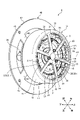
- FIG. 1 is a diagram showing an electric working machine 1 according to the present embodiment.
- the electric working machine 1 is a lawn mower which is a kind of gardening tool (Outdoor Power Equipment).
- the electric work machine 1 includes a housing 2, wheels 3, a motor 4, a cutting blade 5, a cutting box 6, a handle 7, and a battery mounting portion 8.
- the housing 2 accommodates the motor 4 and the cutting blade 5. Each of the wheel 3, the motor 4, and the cutting blade 5 is supported by the housing 2.
- Wheel 3 rotates in contact with the ground. By rotating the wheels 3, the electric work machine 1 can move on the ground. Four wheels 3 are provided.
- the motor 4 is a power source for the electric work machine 1.
- the motor 4 generates a rotational force that rotates the cutting blade 5.
- the motor 4 is arranged above the cutting blade 5.
- the cutting blade 5 is connected to the motor 4.
- the cutting blade 5 is an output unit of the electric working machine 1 driven by the motor 4.
- the cutting blade 5 rotates about the rotation axis AX of the motor 4 due to the rotational force generated by the motor 4.
- the cutting blade 5 faces the ground. With the wheels 3 in contact with the ground, the cutting blade 5 rotates to mow the grass growing on the ground.
- the lawn cut by the cutting blade 5 is housed in the cutting box 6.
- the handle 7 is held by the user of the electric work machine 1. The user can move the electric work machine 1 while holding the handle 7 by hand.
- the battery pack 9 is mounted on the battery mounting portion 8.
- the battery pack 9 is a power source for the electric work machine 1.
- the battery pack 9 is removable from the battery mounting portion 8.
- the battery pack 9 includes a secondary battery.
- the battery pack 9 includes a rechargeable lithium-ion battery.
- the battery pack 9 can supply electric power to the electric work machine 1 by being mounted on the battery mounting portion 8.
- the motor 4 is driven based on the drive current supplied from the battery pack 9.
- FIG. 2 and 3 are perspective views showing the motor 4 according to the present embodiment.
- FIG. 2 is a perspective view from the upper side.
- FIG. 3 is a perspective view from the lower side.
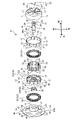
- FIG. 4 is a vertical sectional view showing the motor 4 according to the present embodiment. The vertical sectional view is a sectional view including the rotation axis AX and parallel to the rotation axis AX.
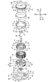
- FIG. 5 is an exploded perspective view showing the motor 4 according to the present embodiment.
- FIG. 6 is a plan view of the motor 4 according to the present embodiment as viewed from below.
- the motor 4 is an outer rotor type brushless motor.
- the motor 4 includes a rotor 10, a rotor shaft 20, a stator 30, a stator base 40, and a sensor substrate 50.
- the rotor 10 rotates with respect to the stator 30. At least a part of the rotor 10 is arranged on the outer peripheral side of the stator 30.
- the rotor shaft 20 is fixed to the rotor 10. At least a portion of the rotor shaft 20 is located inside the stator base 40.
- the rotor 10 and the rotor shaft 20 rotate about the rotation shaft AX.
- the stator base 40 supports the stator 30.
- the stator base 40 is fixed to the stator core 31.
- the cutting blade 5 is connected to the rotor shaft 20. The cutting blade 5 is driven by the rotor 10.
- the sensor board 50 supports a magnetic sensor that detects the rotation of the rotor 10.
- the rotation shaft AX of the motor 4 extends in the vertical direction.
- the axial direction and the vertical direction are parallel.
- one side in the axial direction is appropriately referred to as an upper side, and the other side in the axial direction is appropriately referred to as a lower side.
- the rotor 10 has a rotor cup 11 and a magnet 12.
- the rotor cup 11 is made of a metal containing iron as a main component.
- the magnet 12 is a permanent magnet. At least a part of the rotor cup 11 is arranged on the outer peripheral side of the stator 30.
- the magnet 12 is fixed to the rotor cup 11.
- the rotor cup 11 has a rotor yoke 13, a rotor plate 14, and a radiating rib 15.
- the rotor yoke 13 has a cylindrical shape.
- the rotor yoke 13 is arranged so as to surround the stator 30.
- the rotor yoke 13 is arranged around the rotation axis AX.
- the central axis of the rotor yoke 13 and the rotation axis AX coincide with each other.
- the rotor plate 14 is annular.
- the rotor plate 14 is arranged around the rotation axis AX.
- the central axis of the rotor plate 14 and the rotation axis AX coincide with each other.
- At least a portion of the rotor plate 14 faces the shaft end face 21 of the rotor shaft 20.
- the shaft end surface 21 faces upward.
- the radial rib 15 connects the rotor yoke 13 and the rotor plate 14.
- the radial rib 15 extends radially outward from the rotor plate 14.
- a plurality of radial ribs 15 are provided at intervals in the circumferential direction.
- the rotor yoke 13, the rotor plate 14, and the radiating rib 15 are integrated.
- the magnet 12 is fixed to the rotor yoke 13.
- a plurality of magnets 12 are arranged in the circumferential direction.
- 14 magnets 12 are arranged in the circumferential direction.
- the north pole, the magnet 12, and the south pole magnet 12 are alternately arranged in the circumferential direction.
- the magnet 12 is arranged inside the rotor yoke 13.
- the magnet 12 is fixed to the inner surface of the rotor yoke 13 with, for example, an adhesive.
- the rotor shaft 20 extends in the axial direction.
- the central axis of the rotor shaft 20 and the rotary axis AX coincide with each other.
- the rotor shaft 20 is fixed to the rotor 10 so that the central axis of the rotor shaft 20 and the central axis of the rotor yoke 13 coincide with each other.
- the rotor shaft 20 has a shaft protrusion 22 that projects upward from the shaft end surface 21.
- the rotor plate 14 has a shaft opening 16 in which the shaft protrusion 22 is arranged. By arranging the shaft convex portion 22 in the shaft opening 16, the rotor 10 and the rotor shaft 20 are positioned in the radial direction.
- the rotor 10 and the rotor shaft 20 are positioned in the axial direction by the contact between the shaft end surface 21 around the shaft convex portion 22 and the lower surface of the rotor plate 14.
- the rotor shaft 20 and the rotor plate 14 of the rotor 10 are fixed by the rotor screw 23.
- a screw hole 24 is formed in the shaft end surface 21.
- a screw opening 17 is formed in the rotor plate 14.
- the rotor screw 23 is inserted into the screw hole 24 through the screw opening 17 with the shaft convex portion 22 arranged in the shaft opening 16.
- the rotor 10 and the rotor shaft 20 are fixed by the rotor screw 23 by connecting the thread provided in the rotor screw 23 and the thread groove provided in the screw hole 24.
- the rotor 10 and the rotor shaft 20 are fixed by three rotor screws 23.
- the stator 30 has a stator core 31, an insulator 32, and a coil 33.
- the stator core 31 is made of a metal containing iron as a main component.
- the stator core 31 has a stator yoke 34 and teeth 35.
- the stator yoke 34 has a cylindrical shape.
- the stator yoke 34 is arranged around the rotation axis AX.
- the central axis of the stator yoke 34 and the rotation axis AX coincide with each other.
- the teeth 35 project radially outward from the outer surface of the stator yoke 34.
- a plurality of teeth 35 are provided at intervals in the circumferential direction. In this embodiment, 12 teeth 35 are provided.
- a slot 36 is formed between the teeth 35 adjacent to each other.
- the insulator 32 is made of synthetic resin.
- the insulator 32 is fixed to the stator core 31.
- the insulator 32 covers at least a part of the surface of the stator core 31.
- the insulator 32 covers at least a part of the end face of the stator yoke 34 facing in the axial direction.
- the end surface of the stator yoke 34 includes an upper end surface facing upward and a lower end surface facing downward. Further, the insulator 32 covers at least a part of the outer surface of the stator yoke 34 facing outward in the radial direction. Further, the insulator 32 covers at least a part of the surface of the teeth 35.
- the insulator 32 includes an upper insulator 321 fixed to the upper part of the stator core 31 and a lower insulator 322 fixed to the lower part of the stator core 31.
- the upper insulator 321 is attached to the stator core 31 from the upper side of the stator core 31.
- the lower insulator 322 is attached to the stator core 31 from the lower side of the stator core 31.
- the coil 33 is mounted on the insulator 32.
- the coil 33 is wound around the teeth 35 via the insulator 32.
- the surface of the teeth 35 around which the coil 33 is wound is covered with the insulator 32.
- the outer surface of the teeth 35 facing radially outward is not covered by the insulator 32.
- the stator core 31 and the coil 33 are insulated by the insulator 32.
- a plurality of coils 33 are provided. In this embodiment, 12 coils 33 are arranged in the circumferential direction.
- the sensor board 50 is fixed to the insulator 32.
- the sensor board 50 supports a magnetic sensor that detects the rotation of the rotor 10.
- the sensor substrate 50 is fixed to the insulator 32 so that the magnet 12 and the magnetic sensor face each other.
- the sensor substrate 50 is arranged radially outside the coil 33.
- the stator base 40 supports the stator core 31.
- the stator base 40 is made of aluminum.
- the stator base 40 has a pipe portion 41, a foot portion 42, and a connecting rib portion 43.
- the pipe portion 41 is substantially cylindrical.
- the pipe portion 41 is arranged around the rotation axis AX.
- the central axis of the pipe portion 41 and the rotation axis AX coincide with each other.
- the pipe portion 41 is arranged inside the stator core 31.
- the central axis of the pipe portion 41 and the central axis of the stator yoke 34 coincide with each other.
- the pipe portion 41 includes a small diameter portion 41A and a large diameter portion 41B arranged below the small diameter portion 41A.
- Each of the small diameter portion 41A and the large diameter portion 41B has a cylindrical shape.
- the outer diameter of the large diameter portion 41B is larger than the outer diameter of the small diameter portion 41A.
- the central axis of the pipe portion 41 and the rotation axis AX coincide with each other.
- the stator core 31 is arranged around the small diameter portion 41A.
- the small diameter portion 41A is arranged inside the stator core 31.
- the large diameter portion 41B is arranged outside the stator core 31.
- the stator core 31 is fixed to the pipe portion 41.
- the stator base 40 is fixed to the stator 30 so that the central axis of the pipe portion 41 and the central axis of the stator yoke 34 coincide with each other.
- the pipe portion 41 supports the rotor shaft 20 via the bearing 25.
- the rotor shaft 20 is arranged inside the pipe portion 41.
- the rotor shaft 20 is supported by the pipe portion 41 via the bearing 25.
- the bearing 25 is arranged between the stator base 40 and the rotor shaft 20.
- the bearing 25 is arranged between the inner surface of the pipe portion 41 and the outer surface of the rotor shaft 20.
- the bearing 25 rotatably supports the rotor shaft 20.
- the bearing 25 includes an upper bearing 251 (first bearing) and a lower bearing 252 (second bearing) arranged below the upper bearing 251.
- the upper bearing 251 supports the first portion of the rotor shaft 20.
- the lower bearing 252 supports the second portion of the rotor shaft 20 below the first portion.
- Each of the upper bearing 251 and the lower bearing 252 is arranged between the pipe portion 41 of the stator base 40 and the rotor shaft 20.
- the bearing 25 and at least a part of the stator core 31 overlap. That is, in the axial direction, the position of the bearing 25 and the position of at least a part of the stator core 31 coincide with each other.
- the bearing 25 includes an upper bearing 251 and a lower bearing 252. In the axial direction, one or both of the upper bearing 251 and the lower bearing 252 overlap with at least a part of the stator core 31. As shown in FIG. 4, in the present embodiment, the upper bearing 251 and at least a part of the stator core 31 overlap in the axial direction. In the axial direction, the lower bearing 252 and at least a part of the stator core 31 may overlap, or both the upper bearing 251 and the lower bearing 252 overlap with at least a part of the stator core 31. May be good.
- the upper bearing 251 has an upper end surface 253 (first end surface) facing upward and a lower end surface 254 (second end surface) facing downward.
- the rotor shaft 20 has a first support surface 28 that supports the upper end surface 253.
- the stator base 40 has a second support surface 413 that supports the lower end surface 254, the first support surface 28 facing downward.
- the second support surface 413 faces upward.
- a step 29 is provided on at least a part of the outer surface of the rotor shaft 20.
- the first support surface 28 includes the lower surface of the step portion 29 facing downward.
- the first support surface 28 contacts a part of the upper end surface 253 on the inner side in the radial direction.
- a step portion 414 is provided on at least a part of the inner surface of the pipe portion 41.
- the second support surface 413 includes the upper surface of the step portion 414 facing upward.
- the second support surface 413 contacts a part of the lower end surface 254 on the outer side in the radial direction.
- the inner surface of the upper bearing 251 facing inward in the radial direction contacts the outer surface of the rotor shaft 20.
- the outer surface of the upper bearing 251 facing outward in the radial direction contacts the inner surface of the pipe portion 41.
- the upper bearing 251 is sandwiched between the first support surface 28 and the second support surface 413 in the axial direction.
- the upper bearing 251 is sandwiched between the outer surface of the rotor shaft 20 and the inner surface of the pipe portion 41 in the radial direction. As a result, the upper bearing 251 and the rotor shaft 20 and the stator base 40 are positioned.
- the lower bearing 252 has an upper end surface 255 (third end surface) facing upward and a lower end surface 256 (fourth end surface) facing downward.
- the stator base 40 has a third support surface 415 that supports the upper end surface 255, the third support surface 415 facing downward.
- a step portion 416 is provided on at least a part of the inner surface of the pipe portion 41.
- the third support surface 415 includes the lower surface of the step portion 416 facing downward.
- the third support surface 415 contacts a part of the upper end surface 255 on the outer side in the radial direction.
- a circlip 27 that supports the lower end surface 256 is attached to the rotor shaft 20.
- a groove 200 is formed on a part of the outer surface of the rotor shaft 20.
- At least a portion of the circlip 27 is located inside the groove 200.
- the circlip 27 contacts a part of the lower end surface 256 on the inner side in the radial direction.
- the inner surface of the lower bearing 252 facing inward in the radial direction contacts the outer surface of the rotor shaft 20.
- the outer surface of the lower bearing 252 facing outward in the radial direction contacts the inner surface of the pipe portion 41.
- the lower bearing 252 is sandwiched between the third support surface 415 and the circlip 27 in the axial direction.
- the lower bearing 252 is sandwiched between the outer surface of the rotor shaft 20 and the inner surface of the pipe portion 41 in the radial direction.
- the lower bearing 252 is fixed to the pipe portion 41 by the bearing fixing screw 26.
- a screw boss 48 is provided at the lower end of the pipe portion 41.
- the bearing fixing screw 26 is inserted into a screw hole provided in the screw boss 48.
- the head of the bearing fixing screw 26 becomes the lower end surface of the lower bearing 252.
- the lower bearing 252 is fixed to the pipe portion 41 by the contact between the head of the bearing fixing screw 26 and the lower bearing 252.
- the foot portion 42 is arranged outside the stator core 31.
- the foot portion 42 is annular.
- the foot portion 42 has a plate shape.
- the central axis of the pipe portion 41 and the central axis of the foot portion 42 coincide with each other.
- the foot portion 42 is fixed to the fixing target.
- a fixing target a housing 2 accommodating a motor 4 is exemplified. By fixing the foot portion 42 to the fixing target, the motor 4 is fixed to the fixing target.
- the inner diameter of the foot portion 42 is larger than the outer diameter of the pipe portion 41.
- the foot portion 42 is provided with a screw opening 45.
- a screw (not shown) is arranged in the screw opening 45.
- the foot portion 42 and the fixing target are fixed by connecting the screw arranged in the screw opening 45 to the screw hole provided in the fixing target.
- the connecting rib portion 43 connects the pipe portion 41 and the foot portion 42.
- the connecting rib portion 43 extends radially outward from the outer surface of the pipe portion 41.
- a plurality of connecting rib portions 43 are provided at intervals in the circumferential direction. In this embodiment, four connecting rib portions 43 are provided.
- the connecting rib portion 43 connects the large diameter portion 41B of the pipe portion 41 and the foot portion 42.
- the radial inner end of the connecting rib portion 43 is fixed to the outer surface of the large diameter portion 41B.
- the radial outer end of the connecting rib portion 43 is fixed to the inner surface of the foot portion 42.
- the connecting rib portion 43 connects the pipe portion 41 and the foot portion 42 so that the central axis of the pipe portion 41 and the central axis of the foot portion 42 coincide with each other.
- the stator 30 has a stator screw 37 that fixes the stator base 40 and the stator core 31.
- a screw opening 38 is formed in the stator core 31.
- the screw opening 38 of the stator core 31 is formed so as to penetrate the upper end surface and the lower end surface of the stator yoke 34.
- a screw hole 47 is formed on the end surface of the stator base 40 facing upward of the large diameter portion 41B.
- the stator screw 37 is inserted into the screw opening 38 of the stator core 31 from the upper side of the stator core 31.
- the stator screw 37 is inserted into the screw hole 47 of the stator base 40 through the screw opening 38 of the stator core 31.
- the stator core 31 and the stator base 40 are fixed by the stator screw 37 by connecting the thread provided in the stator screw 37 and the thread groove provided in the screw hole 47.
- the stator core 31 and the stator base 40 are fixed by three stator screws 37.
- the motor 4 is a three-phase brushless motor.
- Each of the twelve coils 33 is assigned to any one of the U (UV) phase, the V (VW) phase, and the W (WU) phase.
- the drive current supplied from the battery pack 9 to the motor 4 includes a U-phase drive current, a V-phase drive current, and a W-phase drive current.
- the drive current from the battery pack 9 is supplied to the coil 33 via a bus bar (not shown).
- a rotating magnetic field is generated in the stator 30 by supplying a drive current from the battery pack 9 to the coil 33. When a rotating magnetic field is generated in the stator 30, the rotor 10 and the rotor shaft 20 rotate around the rotating shaft AX.
- the bearing 25 and at least a part of the stator core 31 overlap in the axial direction. As a result, the increase in the size of the motor 4 in the axial direction is suppressed.
- both the upper bearing 251 and the lower bearing 252 are arranged between the pipe portion 41 of the stator base 40 and the rotor shaft 20. As a result, the increase in the size of the motor 4 in the axial direction is suppressed.
- the upper end surface 253 of the upper bearing 251 comes into contact with the first support surface 28 of the rotor shaft 20.
- the lower end surface 254 of the upper bearing 251 contacts the second support surface 413 of the stator base 40.
- the upper bearing 251 is inserted into the inside of the pipe portion 41 from the upper side of the pipe portion 41 together with the rotor shaft 20 in a state of being in contact with the first support surface 28, whereby the first support surface 28 and the second support are supported. It is sandwiched between the surface 413 and the surface 413. As a result, the upper bearing 251 and the rotor shaft 20 and the stator base 40 are positioned.
- the upper end surface 255 of the lower bearing 252 contacts the third support surface 415 of the stator base 40.
- the lower bearing 252 can come into contact with the third support surface 415 by being inserted into the inside of the pipe portion 41 from the lower side of the pipe portion 41.
- the circlip 27 is arranged in the groove 200, so that the lower bearing 252 is sandwiched between the third support surface 415 and the circlip 27 in the axial direction. Is done.
- the lower bearing 252, the rotor shaft 20, and the stator base 40 are positioned.
- a rotor screw 23 for fixing the rotor shaft 20 and the rotor plate 14 is provided.
- the rotor shaft 20 and the rotor 10 are easily fixed by the rotor screw 23.
- the shaft convex portion 22 of the rotor shaft 20 is arranged in the shaft opening 16 of the rotor plate 14. As a result, the rotor 10 and the rotor shaft 20 are positioned.
- the rotor yoke 13, the rotor plate 14, and the radiating rib 15 are integrated. As a result, changes in the relative positions of the magnet 12 fixed to the rotor yoke 13 and the rotor yoke 13 and the rotor plate 14 and the rotor shaft 20 fixed to the rotor plate 14 are suppressed.
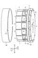
- FIG. 7 and 8 are perspective views showing the motor 4 according to the present embodiment.
- FIG. 7 is a perspective view from the upper side.
- FIG. 8 is a perspective view from the lower side.
- FIG. 9 is an exploded perspective view showing the motor 4 according to the present embodiment.
- the insulator 32 includes the upper insulator 321 and the lower insulator 322.
- the insulator 32 is integrally molded with the stator core 31.
- the insulator 32 is fixed to the stator core by, for example, insert molding.
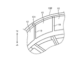
- the rotor cup 11 includes a cylindrical rotor yoke 13B, a rotor plate 14B at least partially facing the shaft end face 21, and a rotor ring 18 fixed to the rotor plate 14B via a connecting rib 180. It has a columnar rib 19 extending axially from the rotor ring 18.
- the rotor yoke 13B is formed, for example, by drawing.
- the rotor plate 14B, the connecting rib 180, the rotor ring 18, and the columnar rib 19 are integrated.
- the rotor yoke 13B and the rotor plate 14B are separate bodies.
- the columnar rib 19 projects downward from the rotor ring 18.
- a plurality of columnar ribs 19 are provided at intervals in the circumferential direction. In this embodiment, 14 columnar ribs 19 are provided.
- FIG. 10 is an exploded perspective view showing the rotor 10 according to the present embodiment.
- the magnet 12 is arranged inside the rotor yoke 13B.
- the columnar rib 19 is inserted inside the rotor yoke 13B.
- the columnar rib 19 comes into contact with the magnet 12.
- the columnar ribs 19 are arranged between magnets 12 that are adjacent to each other in the circumferential direction.
- the magnet 12 is positioned by the columnar rib 19.
- the rotor yoke 13B and the rotor ring 18 are connected.
- the rotor ring 18 has a ring large diameter portion 18A that contacts the upper end surface of the rotor yoke 13B, and a ring small diameter portion 18B that is arranged inside the rotor yoke 13B.
- the ring small diameter portion 18B fits inside the rotor yoke 13B in a state where the upper end surface of the rotor yoke 13B is in contact with the ring large diameter portion 18A.
- the outer surface of the ring small diameter portion 18B contacts the inner surface of the rotor yoke 13B.
- the rotor yoke 13B and the rotor ring 18 are positioned in the axial direction by the contact between the upper end surface of the rotor yoke 13B and the ring large diameter portion 18A.
- the ring small diameter portion 18B fits inside the rotor yoke 13B, and the outer surface of the ring small diameter portion 18B and the inner surface of the rotor yoke 13B come into contact with each other, so that the rotor yoke 13B and the rotor ring 18 are positioned in the radial direction.
- the rotor ring 18 has a ring convex portion 181 protruding downward from the lower end surface of the ring large diameter portion 18A.
- the rotor yoke 13B has a ring recess 130 in which the ring protrusion 181 is arranged. By arranging the ring protrusion 181 on the rotor yoke 13B, the rotor yoke 13B and the rotor ring 18 are positioned in the circumferential direction.
- One ring convex portion 181 is provided.
- One ring recess 130 is provided. In the circumferential direction, the boundary between the magnets 12 adjacent to each other and at least a part of the ring recess 130 overlap. That is, in the circumferential direction, the position of one columnar rib 19 and the position of the ring convex portion 181 coincide with each other.
- the rotor yoke 13B and the rotor plate 14B are separate bodies.
- the rotor yoke 13B can be easily manufactured, for example, by drawing.
- the rotor ring 18 is fixed to the rotor plate 14B via the connecting rib 180.
- a columnar rib 19 extends axially from the rotor ring 18. The columnar ribs 19 allow the magnet 12 to be easily positioned. This improves the productivity of the motor 4.
- the rotor ring 18 has a ring large diameter portion 18A that contacts the upper end surface of the rotor yoke 13B and a ring small diameter portion 18B that is arranged inside the rotor yoke 13B.
- the rotor yoke 13B and the rotor ring 18 are positioned in the axial direction by the contact between the upper end surface of the rotor yoke 13B and the ring large diameter portion 18A.
- the ring small diameter portion 18B inside the rotor yoke 13B, the rotor yoke 13B and the rotor ring 18 are positioned in the radial direction.
- the rotor ring 18 has a ring convex portion 181 protruding downward from the lower end surface of the ring large diameter portion 18A.
- the rotor yoke 13B has a ring recess 130 in which the ring protrusion 181 is arranged.
- the ring convex portion 181 is arranged in the ring concave portion 130, the rotor yoke 13B and the rotor ring 18 are positioned. Further, since the ring convex portion 181 projects downward from the lower end surface of the ring large diameter portion 18A, it is possible to prevent the rotor ring 18 from becoming larger in the radial direction.
- the boundary between the magnets 12 adjacent to each other and at least a part of the ring recess 130 overlap. That is, the ring concave portion 130 and the ring convex portion 181 are arranged at positions in the rotor 10 where the passage of magnetic force lines is small. As a result, deterioration of the performance of the motor 4 is suppressed.
- FIG. 11 is a perspective view showing a part of a modified example of the rotor 10 according to the present embodiment.
- the groove 131 may be provided on the inner surface of the rotor yoke 13B.
- the groove 131 is provided on the inner surface of the rotor yoke 13B so as to extend in the axial direction.
- FIG. 12 is a perspective view showing a part of a modified example of the rotor 10 according to the present embodiment.
- a protruding rib 132 may be provided on the inner surface of the rotor yoke 13B.
- the protruding rib 132 projects radially inward from the inner surface of the rotor yoke 13B.
- the magnet 12 is arranged inside the rotor yoke 13B.
- the protruding ribs 132 are arranged between magnets 12 adjacent to each other. The protruding rib 132 positions the rotor yoke 13B and the magnet 12 in the circumferential direction.
- the protruding ribs 132 and the columnar ribs 19 may be arranged alternately in the circumferential direction. That is, the protruding ribs 132 may be arranged between the columnar ribs 19 that are adjacent to each other in the circumferential direction. As a result, the rotor yoke 13B, the rotor ring 18, and the magnet 12 are positioned in the circumferential direction.
- FIG. 13 is a perspective view showing the rotor 10 according to the present embodiment.
- FIG. 14 is an exploded perspective view showing the rotor 10 according to the present embodiment.
- the rotor yoke 13B has a first yoke portion 1301, a second yoke portion 1302, a third yoke portion 1303, and a fourth yoke portion 1304.
- Each of the first yoke portion 1301, the second yoke portion 1302, the third yoke portion 1303, and the fourth yoke portion 1304 is ring-shaped.
- the second yoke portion 1302 is connected to the first yoke portion 1301.
- the third yoke portion 1303 is connected to the second yoke portion 1302.
- the fourth yoke portion 1304 is connected to the third yoke portion 1303.
- the first yoke portion 1301 has a yoke large diameter portion 13C that contacts the upper end surface of the second yoke portion 1302 and a yoke small diameter portion 13D that is arranged inside the second yoke portion 1302.
- the second yoke portion 1302 has a yoke large diameter portion 13C that contacts the upper end surface of the third yoke portion 1303, and a yoke small diameter portion 13D that is arranged inside the third yoke portion 1303.
- the third yoke portion 1303 has a yoke large diameter portion 13C that contacts the upper end surface of the fourth yoke portion 1304, and a yoke small diameter portion 13D that is arranged inside the fourth yoke portion 1304.
- the first yoke portion 1301 has a yoke convex portion 133 that projects downward from the lower surface of the yoke large diameter portion 13C of the first yoke portion 1301.
- the second yoke portion 1302 has a yoke recess 134 in which the yoke convex portion 133 of the first yoke portion 1301 is arranged.
- the yoke recess 134 of the second yoke portion 1302 is provided on the upper end surface of the second yoke portion 1302.
- the second yoke portion 1302 has a yoke convex portion 133 projecting downward from the lower surface of the yoke large diameter portion 13C of the second yoke portion 1302.
- the third yoke portion 1303 has a yoke recess 134 in which the yoke convex portion 133 of the second yoke portion 1302 is arranged.
- the third yoke portion 1303 has a yoke convex portion 133 that projects downward from the lower surface of the yoke large diameter portion 13C of the third yoke portion 1303.
- the fourth yoke portion 1304 has a yoke recess 134 in which the yoke convex portion 133 of the third yoke portion 1303 is arranged.
- the first yoke portion 1301 and the second yoke portion 1302 are positioned in the axial direction by the contact between the yoke large diameter portion 13C of the first yoke portion 1301 and the upper end surface of the second yoke portion 1302.
- the yoke small diameter portion 13D of the first yoke portion 1301 is arranged inside the second yoke portion 1302, and the inside of the second yoke portion 1302 and the outer surface of the yoke small diameter portion 13D come into contact with each other, so that the first yoke portion in the radial direction is formed.
- the 1301 and the second yoke portion 1302 are positioned.
- the first yoke portion 1301 and the second yoke portion 1302 are positioned in the circumferential direction.
- the second yoke portion 1302 and the third yoke portion 1303 are positioned, and the third yoke portion 1303 and the fourth yoke portion 1304 are positioned.
- the rotor yoke 13B may be composed of a plurality of yoke portions (1301, 1302, 1303, 1304). Each of the plurality of yoke portions (1301, 1302, 1303, 1304) is manufactured, for example, by drawing. Since the rotor yoke 13B is composed of a plurality of yoke portions (1301, 1302, 1303, 1304), the loss due to the eddy current is reduced.
- the first yoke portion 1301 has a yoke large diameter portion 13C that contacts the upper end surface of the second yoke portion 1302 and a yoke small diameter portion 13D that is arranged inside the second yoke portion 1302.
- the first yoke portion 1301 and the second yoke portion 1302 are positioned in the axial direction by the contact between the yoke large diameter portion 13C of the first yoke portion 1301 and the upper end surface of the second yoke portion 1302.
- the yoke small diameter portion 13D of the first yoke portion 1301 is arranged inside the second yoke portion 1302, and the inner surface of the second yoke portion 1302 and the outer surface of the yoke small diameter portion 13D of the first yoke portion 1301 come into contact with each other to form a diameter.
- the first yoke portion 1301 and the second yoke portion 1302 are positioned in the direction.
- the first yoke portion 1301 has a yoke convex portion 133 projecting axially from the yoke large diameter portion 13C
- the second yoke portion 1302 has a yoke concave portion 134 in which the yoke convex portion 133 is arranged.
- the electric working machine 1 is a lawn mower which is a kind of gardening tool.
- gardening tools are not limited to lawnmowers. Examples of gardening tools include hedge trimmers, chainsaws, mowers, and blowers. Further, the electric work machine 1 may be an electric tool. Examples of power tools include driver drills, vibration driver drills, angle drills, impact drivers, grinders, hammers, hammer drills, circular saws, and reciprocating saws.
- a battery pack mounted on the battery mounting portion is used as a power source for the electric work machine.
- a commercial power source (AC power source) may be used as a power source for the electric work machine.
- Third support surface, 416 ... Step portion, 1301 ... First yoke portion, 1302 ... Second yoke 1303 ... 3rd yoke part, 1304 ... 4th yoke part, AX ... Rotating shaft.
Abstract
This electric work machine comprises: a stator including a stator core, an insulator fixed to the stator core, and a coil mounted on the insulator; a rotor having a rotor cup, at least a part of which is disposed on the outer circumferential side of the stator and a magnet fixed to the rotor cup; a stator base for supporting the stator core; a rotor shaft, at least a part of which is disposed inside the stator base and which rotates about the rotational axis; an output unit which is driven by the rotor; and a bearing disposed between the stator base and the rotor shaft and supporting the rotor shaft. The bearing and at least a part of the stator core are overlapped with each other in the axial direction of the rotational axis.
Description
本開示は、電動作業機に関する。
This disclosure relates to electric work machines.
電動作業機に係る技術分野において、特許文献1に開示されているような、アウタロータ型のモータを備える電動作業機が知られている。
In the technical field related to electric work machines, electric work machines equipped with an outer rotor type motor as disclosed in Patent Document 1 are known.
電動作業機において、モータの小型化が要求される。特に、モータの回転軸に平行な軸方向の寸法の小型化を実現できる技術が要望される。
In electric work machines, miniaturization of motors is required. In particular, there is a demand for a technique capable of reducing the size of the axial dimension parallel to the rotation axis of the motor.
本開示は、モータを小型化すること目的とする。
The purpose of this disclosure is to reduce the size of the motor.
第1の本開示に従えば、ステータコアと、ステータコアに固定されるインシュレータと、インシュレータに装着されるコイルと、を含むステータと、少なくとも一部がステータの外周側に配置されるロータカップと、ロータカップに固定されるマグネットと、を有するロータと、ステータコアを支持するステータベースと、少なくとも一部がステータベースの内側に配置され回転軸を中心に回転するロータシャフトと、ロータにより駆動される出力部と、ステータベースとロータシャフトとの間に配置されロータシャフトを支持するベアリングと、を備え、回転軸の軸方向において、ベアリングとステータコアの少なくとも一部とはオーバーラップする、電動作業機が提供される。
According to the first disclosure, a stator including a stator core, an insulator fixed to the stator core, a coil mounted on the insulator, a rotor cup at least partially arranged on the outer peripheral side of the stator, and a rotor. A rotor with a magnet fixed to the cup, a stator base that supports the stator core, a rotor shaft that is at least partly located inside the stator base and rotates about a rotation axis, and an output unit driven by the rotor. And a bearing that is located between the stator base and the rotor shaft to support the rotor shaft, and provides an electric working machine that overlaps at least a portion of the bearing and the stator core in the axial direction of the rotating shaft. Ru.
第2の本開示に従えば、ステータコアと、ステータコアに固定されるインシュレータと、インシュレータに装着されるコイルと、を含むステータと、少なくとも一部がステータの外周側に配置されるロータカップと、ロータカップに固定されるマグネットと、を有するロータと、ステータコアを支持するステータベースと、少なくとも一部がステータベースの内側に配置され回転軸を中心に回転するロータシャフトと、ロータにより駆動される出力部と、ステータベースとロータシャフトとの間に配置されロータシャフトの第1部分を支持する第1ベアリングと、ステータベースとロータシャフトとの間に配置されロータシャフトの第2部分を支持する第2ベアリングと、を備える、電動作業機が提供される。
According to a second disclosure, a stator including a stator core, an insulator fixed to the stator core, a coil mounted on the insulator, a rotor cup at least partially arranged on the outer peripheral side of the stator, and a rotor. A rotor with a magnet fixed to the cup, a stator base that supports the stator core, a rotor shaft that is at least partly located inside the stator base and rotates about a rotation axis, and an output unit driven by the rotor. And a first bearing arranged between the stator base and the rotor shaft to support the first portion of the rotor shaft, and a second bearing arranged between the stator base and the rotor shaft to support the second portion of the rotor shaft. And, an electric working machine is provided.
本開示によれば、モータが小型化される。
According to this disclosure, the motor is downsized.
以下、本開示に係る実施形態について図面を参照しながら説明するが、本開示は実施形態に限定されない。以下で説明する実施形態の構成要素は、適宜組み合わせることができる。また、一部の構成要素を用いない場合もある。
Hereinafter, embodiments relating to the present disclosure will be described with reference to the drawings, but the present disclosure is not limited to the embodiments. The components of the embodiments described below can be combined as appropriate. In addition, some components may not be used.
実施形態においては、「左」、「右」、「前」、「後」、「上」、及び「下」の用語を用いて各部の位置関係について説明する。これらの用語は、電動作業機の中心を基準とした相対位置又は方向を示す。
In the embodiment, the positional relationship of each part will be described using the terms "left", "right", "front", "rear", "top", and "bottom". These terms refer to relative positions or orientations relative to the center of the motorized machine.
電動作業機は、モータを有する。実施形態においては、モータの回転軸AXの放射方向を適宜、径方向、と称する。モータの回転軸AXと平行な方向を適宜、軸方向、と称する。モータの回転軸AXを周回する方向を適宜、周方向又は回転方向、と称する。
The electric work machine has a motor. In the embodiment, the radial direction of the rotation shaft AX of the motor is appropriately referred to as a radial direction. The direction parallel to the rotation axis AX of the motor is appropriately referred to as an axial direction. The direction around the rotation axis AX of the motor is appropriately referred to as a circumferential direction or a rotation direction.
径方向においてモータの回転軸AXに近い位置又は接近する方向を適宜、径方向内側、と称し、径方向においてモータの回転軸AXから遠い位置又は離隔する方向を適宜、径方向外側、と称する。軸方向の一方側の位置又は一方側の方向を適宜、軸方向一方側、と称し、軸方向の他方側の位置又は他方側の方向を適宜、軸方向他方側、と称する。周方向の一方側の位置又は一方側の方向を適宜、周方向一方側、と称し、周方向の他方側の位置又は他方側の方向を適宜、周方向他方側、と称する。
The position close to or close to the rotation axis AX of the motor in the radial direction is appropriately referred to as the inside in the radial direction, and the position far from or separated from the rotation axis AX of the motor in the radial direction is appropriately referred to as the outside in the radial direction. The position on one side or the direction on one side in the axial direction is appropriately referred to as one side in the axial direction, and the position on the other side or the direction on the other side in the axial direction is appropriately referred to as the other side in the axial direction. The position on one side or the direction on one side in the circumferential direction is appropriately referred to as one side in the circumferential direction, and the position on the other side or the direction on the other side in the circumferential direction is appropriately referred to as the other side in the circumferential direction.
[第1実施形態]
第1実施形態について説明する。図1は、本実施形態に係る電動作業機1を示す図である。本実施形態において、電動作業機1は、園芸工具(Outdoor Power Equipment)の一種である芝刈り機である。 [First Embodiment]
The first embodiment will be described. FIG. 1 is a diagram showing an electric working machine 1 according to the present embodiment. In the present embodiment, the electric working machine 1 is a lawn mower which is a kind of gardening tool (Outdoor Power Equipment).
図1に示すように、電動作業機1は、ハウジング2と、車輪3と、モータ4と、刈刃5と、刈取りボックス6と、ハンドル7と、バッテリ装着部8とを備える。
As shown in FIG. 1, the electric work machine 1 includes a housing 2, wheels 3, a motor 4, a cutting blade 5, a cutting box 6, a handle 7, and a battery mounting portion 8.
ハウジング2は、モータ4及び刈刃5を収容する。車輪3、モータ4、及び刈刃5のそれぞれは、ハウジング2に支持される。
The housing 2 accommodates the motor 4 and the cutting blade 5. Each of the wheel 3, the motor 4, and the cutting blade 5 is supported by the housing 2.
車輪3は、地面に接触した状態で回転する。車輪3が回転することにより、電動作業機1は、地面を移動することができる。車輪3は、4つ設けられる。
Wheel 3 rotates in contact with the ground. By rotating the wheels 3, the electric work machine 1 can move on the ground. Four wheels 3 are provided.
モータ4は、電動作業機1の動力源である。モータ4は、刈刃5を回転させる回転力を発生する。モータ4は、刈刃5よりも上方に配置される。
The motor 4 is a power source for the electric work machine 1. The motor 4 generates a rotational force that rotates the cutting blade 5. The motor 4 is arranged above the cutting blade 5.
刈刃5は、モータ4に連結される。刈刃5は、モータ4により駆動される電動作業機1の出力部である。刈刃5は、モータ4が発生する回転力により、モータ4の回転軸AXを中心に回転する。刈刃5は、地面に対向する。車輪3が地面に接触している状態で、刈刃5が回転することにより、地面に生えている芝が刈られる。刈刃5により刈られた芝は、刈取りボックス6に収容される。
The cutting blade 5 is connected to the motor 4. The cutting blade 5 is an output unit of the electric working machine 1 driven by the motor 4. The cutting blade 5 rotates about the rotation axis AX of the motor 4 due to the rotational force generated by the motor 4. The cutting blade 5 faces the ground. With the wheels 3 in contact with the ground, the cutting blade 5 rotates to mow the grass growing on the ground. The lawn cut by the cutting blade 5 is housed in the cutting box 6.
ハンドル7は、電動作業機1の使用者の手で握られる。使用者は、ハンドル7を手で握った状態で、電動作業機1を移動させることができる。
The handle 7 is held by the user of the electric work machine 1. The user can move the electric work machine 1 while holding the handle 7 by hand.
バッテリ装着部8に、バッテリパック9が装着される。バッテリパック9は、電動作業機1の電源である。バッテリパック9は、バッテリ装着部8に着脱可能である。バッテリパック9は、二次電池を含む。本実施形態において、バッテリパック9は、充電式のリチウムイオン電池を含む。バッテリパック9は、バッテリ装着部8に装着されることにより、電動作業機1に電力を供給可能である。モータ4は、バッテリパック9から供給される駆動電流に基づいて駆動する。
The battery pack 9 is mounted on the battery mounting portion 8. The battery pack 9 is a power source for the electric work machine 1. The battery pack 9 is removable from the battery mounting portion 8. The battery pack 9 includes a secondary battery. In this embodiment, the battery pack 9 includes a rechargeable lithium-ion battery. The battery pack 9 can supply electric power to the electric work machine 1 by being mounted on the battery mounting portion 8. The motor 4 is driven based on the drive current supplied from the battery pack 9.
図2及び図3のそれぞれは、本実施形態に係るモータ4を示す斜視図である。図2は、上方側からの斜視図である。図3は、下方側からの斜視図である。図4は、本実施形態に係るモータ4を示す縦断面図である。縦断面図は、回転軸AXを含み且つ回転軸AXに平行な断面図である。図5は、本実施形態に係るモータ4を示す分解斜視図である。図6は、本実施形態に係るモータ4を下方から見た平面図である。本実施形態において、モータ4は、アウタロータ型のブラシレスモータである。
2 and 3 are perspective views showing the motor 4 according to the present embodiment. FIG. 2 is a perspective view from the upper side. FIG. 3 is a perspective view from the lower side. FIG. 4 is a vertical sectional view showing the motor 4 according to the present embodiment. The vertical sectional view is a sectional view including the rotation axis AX and parallel to the rotation axis AX. FIG. 5 is an exploded perspective view showing the motor 4 according to the present embodiment. FIG. 6 is a plan view of the motor 4 according to the present embodiment as viewed from below. In the present embodiment, the motor 4 is an outer rotor type brushless motor.
図2、図3、図4、図5、及び図6に示すように、モータ4は、ロータ10と、ロータシャフト20と、ステータ30と、ステータベース40と、センサ基板50とを備える。ロータ10は、ステータ30に対して回転する。ロータ10の少なくとも一部は、ステータ30の外周側に配置される。ロータシャフト20は、ロータ10に固定される。ロータシャフト20の少なくとも一部は、ステータベース40の内側に配置される。ロータ10及びロータシャフト20は、回転軸AXを中心に回転する。ステータベース40は、ステータ30を支持する。ステータベース40は、ステータコア31に固定される。刈刃5は、ロータシャフト20に接続される。刈刃5は、ロータ10により駆動される。センサ基板50は、ロータ10の回転を検出する磁気センサを支持する。
As shown in FIGS. 2, 3, 4, 5, and 6, the motor 4 includes a rotor 10, a rotor shaft 20, a stator 30, a stator base 40, and a sensor substrate 50. The rotor 10 rotates with respect to the stator 30. At least a part of the rotor 10 is arranged on the outer peripheral side of the stator 30. The rotor shaft 20 is fixed to the rotor 10. At least a portion of the rotor shaft 20 is located inside the stator base 40. The rotor 10 and the rotor shaft 20 rotate about the rotation shaft AX. The stator base 40 supports the stator 30. The stator base 40 is fixed to the stator core 31. The cutting blade 5 is connected to the rotor shaft 20. The cutting blade 5 is driven by the rotor 10. The sensor board 50 supports a magnetic sensor that detects the rotation of the rotor 10.
本実施形態において、モータ4の回転軸AXは、上下方向に延伸する。軸方向と上下方向とは、平行である。以下の説明において、軸方向一方側を適宜、上方側、と称し、軸方向他方側を適宜、下方側、と称する。
In the present embodiment, the rotation shaft AX of the motor 4 extends in the vertical direction. The axial direction and the vertical direction are parallel. In the following description, one side in the axial direction is appropriately referred to as an upper side, and the other side in the axial direction is appropriately referred to as a lower side.
ロータ10は、ロータカップ11と、マグネット12とを有する。ロータカップ11は、鉄を主成分とする金属製である。マグネット12は、永久磁石である。ロータカップ11の少なくとも一部は、ステータ30の外周側に配置される。マグネット12は、ロータカップ11に固定される。
The rotor 10 has a rotor cup 11 and a magnet 12. The rotor cup 11 is made of a metal containing iron as a main component. The magnet 12 is a permanent magnet. At least a part of the rotor cup 11 is arranged on the outer peripheral side of the stator 30. The magnet 12 is fixed to the rotor cup 11.
ロータカップ11は、ロータヨーク13と、ロータプレート14と、放射リブ15とを有する。
The rotor cup 11 has a rotor yoke 13, a rotor plate 14, and a radiating rib 15.
ロータヨーク13は、円筒状である。ロータヨーク13は、ステータ30を囲むように配置される。ロータヨーク13は、回転軸AXの周囲に配置される。ロータヨーク13の中心軸と回転軸AXとは、一致する。ロータプレート14は、円環状である。ロータプレート14は、回転軸AXの周囲に配置される。ロータプレート14の中心軸と回転軸AXとは、一致する。ロータプレート14の少なくとも一部は、ロータシャフト20のシャフト端面21に対向する。シャフト端面21は、上方側を向く。放射リブ15は、ロータヨーク13とロータプレート14とを繋ぐ。放射リブ15は、ロータプレート14から径方向外側に延伸する。放射リブ15は、周方向に間隔をあけて複数設けられる。ロータヨーク13とロータプレート14と放射リブ15とは、一体である。
The rotor yoke 13 has a cylindrical shape. The rotor yoke 13 is arranged so as to surround the stator 30. The rotor yoke 13 is arranged around the rotation axis AX. The central axis of the rotor yoke 13 and the rotation axis AX coincide with each other. The rotor plate 14 is annular. The rotor plate 14 is arranged around the rotation axis AX. The central axis of the rotor plate 14 and the rotation axis AX coincide with each other. At least a portion of the rotor plate 14 faces the shaft end face 21 of the rotor shaft 20. The shaft end surface 21 faces upward. The radial rib 15 connects the rotor yoke 13 and the rotor plate 14. The radial rib 15 extends radially outward from the rotor plate 14. A plurality of radial ribs 15 are provided at intervals in the circumferential direction. The rotor yoke 13, the rotor plate 14, and the radiating rib 15 are integrated.
マグネット12は、ロータヨーク13に固定される。マグネット12は、周方向に複数配置される。本実施形態において、マグネット12は、周方向に14個配置される。N極とマグネット12とS極のマグネット12とが周方向に交互に配置される。本実施形態において、マグネット12は、ロータヨーク13の内側に配置される。マグネット12は、例えば接着剤によりロータヨーク13の内面に固定される。
The magnet 12 is fixed to the rotor yoke 13. A plurality of magnets 12 are arranged in the circumferential direction. In this embodiment, 14 magnets 12 are arranged in the circumferential direction. The north pole, the magnet 12, and the south pole magnet 12 are alternately arranged in the circumferential direction. In this embodiment, the magnet 12 is arranged inside the rotor yoke 13. The magnet 12 is fixed to the inner surface of the rotor yoke 13 with, for example, an adhesive.
ロータシャフト20は、軸方向に延伸する。ロータシャフト20の中心軸と回転軸AXとは、一致する。ロータシャフト20は、ロータシャフト20の中心軸とロータヨーク13の中心軸とが一致するように、ロータ10に固定される。ロータシャフト20は、シャフト端面21から上方側に突出するシャフト凸部22を有する。ロータプレート14は、シャフト凸部22が配置されるシャフト開口16を有する。シャフト開口16にシャフト凸部22が配置されることにより、径方向においてロータ10とロータシャフト20とが位置決めされる。シャフト凸部22の周囲のシャフト端面21とロータプレート14の下面とが接触することにより、軸方向においてロータ10とロータシャフト20とが位置決めされる。
The rotor shaft 20 extends in the axial direction. The central axis of the rotor shaft 20 and the rotary axis AX coincide with each other. The rotor shaft 20 is fixed to the rotor 10 so that the central axis of the rotor shaft 20 and the central axis of the rotor yoke 13 coincide with each other. The rotor shaft 20 has a shaft protrusion 22 that projects upward from the shaft end surface 21. The rotor plate 14 has a shaft opening 16 in which the shaft protrusion 22 is arranged. By arranging the shaft convex portion 22 in the shaft opening 16, the rotor 10 and the rotor shaft 20 are positioned in the radial direction. The rotor 10 and the rotor shaft 20 are positioned in the axial direction by the contact between the shaft end surface 21 around the shaft convex portion 22 and the lower surface of the rotor plate 14.
本実施形態において、ロータシャフト20とロータ10のロータプレート14とは、ロータねじ23により固定される。シャフト端面21にねじ孔24が形成される。ロータプレート14にねじ用開口17が形成される。シャフト開口16にシャフト凸部22が配置された状態で、ロータねじ23がねじ用開口17を介してねじ孔24に挿入される。ロータねじ23に設けられているねじ山とねじ孔24に設けられているねじ溝とが結合されることにより、ロータ10とロータシャフト20とがロータねじ23により固定される。本実施形態において、ロータ10とロータシャフト20とは、3つのロータねじ23により固定される。
In the present embodiment, the rotor shaft 20 and the rotor plate 14 of the rotor 10 are fixed by the rotor screw 23. A screw hole 24 is formed in the shaft end surface 21. A screw opening 17 is formed in the rotor plate 14. The rotor screw 23 is inserted into the screw hole 24 through the screw opening 17 with the shaft convex portion 22 arranged in the shaft opening 16. The rotor 10 and the rotor shaft 20 are fixed by the rotor screw 23 by connecting the thread provided in the rotor screw 23 and the thread groove provided in the screw hole 24. In the present embodiment, the rotor 10 and the rotor shaft 20 are fixed by three rotor screws 23.
ステータ30は、ステータコア31と、インシュレータ32と、コイル33とを有する。
The stator 30 has a stator core 31, an insulator 32, and a coil 33.
ステータコア31は、鉄を主成分とする金属製である。ステータコア31は、ステータヨーク34と、ティース35とを有する。ステータヨーク34は、円筒状である。ステータヨーク34は、回転軸AXの周囲に配置される。ステータヨーク34の中心軸と回転軸AXとは、一致する。ティース35は、ステータヨーク34の外面から径方向外側に突出する。ティース35は、周方向に間隔をあけて複数設けられる。本実施形態において、ティース35は、12個設けられる。相互に隣り合うティース35の間にスロット36が形成される。
The stator core 31 is made of a metal containing iron as a main component. The stator core 31 has a stator yoke 34 and teeth 35. The stator yoke 34 has a cylindrical shape. The stator yoke 34 is arranged around the rotation axis AX. The central axis of the stator yoke 34 and the rotation axis AX coincide with each other. The teeth 35 project radially outward from the outer surface of the stator yoke 34. A plurality of teeth 35 are provided at intervals in the circumferential direction. In this embodiment, 12 teeth 35 are provided. A slot 36 is formed between the teeth 35 adjacent to each other.
インシュレータ32は、合成樹脂製である。インシュレータ32は、ステータコア31に固定される。
The insulator 32 is made of synthetic resin. The insulator 32 is fixed to the stator core 31.
インシュレータ32は、ステータコア31の表面の少なくとも一部を覆う。インシュレータ32は、軸方向を向くステータヨーク34の端面の少なくとも一部を覆う。ステータヨーク34の端面は、上方側を向く上端面と、下方側を向く下端面とを含む。また、インシュレータ32は、径方向外側を向くステータヨーク34の外面の少なくとも一部を覆う。また、インシュレータ32は、ティース35の表面の少なくとも一部を覆う。
The insulator 32 covers at least a part of the surface of the stator core 31. The insulator 32 covers at least a part of the end face of the stator yoke 34 facing in the axial direction. The end surface of the stator yoke 34 includes an upper end surface facing upward and a lower end surface facing downward. Further, the insulator 32 covers at least a part of the outer surface of the stator yoke 34 facing outward in the radial direction. Further, the insulator 32 covers at least a part of the surface of the teeth 35.
本実施形態において、インシュレータ32は、ステータコア31の上部に固定される上側インシュレータ321と、ステータコア31の下部に固定される下側インシュレータ322とを含む。上側インシュレータ321は、ステータコア31の上方側からステータコア31に装着される。下側インシュレータ322は、ステータコア31の下方側からステータコア31に装着される。
In the present embodiment, the insulator 32 includes an upper insulator 321 fixed to the upper part of the stator core 31 and a lower insulator 322 fixed to the lower part of the stator core 31. The upper insulator 321 is attached to the stator core 31 from the upper side of the stator core 31. The lower insulator 322 is attached to the stator core 31 from the lower side of the stator core 31.
コイル33は、インシュレータ32に装着される。コイル33は、インシュレータ32を介してティース35に巻かれる。コイル33が巻かれるティース35の表面は、インシュレータ32に覆われる。径方向外側を向くティース35の外面は、インシュレータ32に覆われない。ステータコア31とコイル33とは、インシュレータ32により絶縁される。コイル33は、複数設けられる。本実施形態において、コイル33は、周方向に12個配置される。
The coil 33 is mounted on the insulator 32. The coil 33 is wound around the teeth 35 via the insulator 32. The surface of the teeth 35 around which the coil 33 is wound is covered with the insulator 32. The outer surface of the teeth 35 facing radially outward is not covered by the insulator 32. The stator core 31 and the coil 33 are insulated by the insulator 32. A plurality of coils 33 are provided. In this embodiment, 12 coils 33 are arranged in the circumferential direction.
センサ基板50は、インシュレータ32に固定される。センサ基板50は、ロータ10の回転を検出する磁気センサを支持する。センサ基板50は、マグネット12と磁気センサとが対向するように、インシュレータ32に固定される。センサ基板50は、コイル33よりも径方向外側に配置される。
The sensor board 50 is fixed to the insulator 32. The sensor board 50 supports a magnetic sensor that detects the rotation of the rotor 10. The sensor substrate 50 is fixed to the insulator 32 so that the magnet 12 and the magnetic sensor face each other. The sensor substrate 50 is arranged radially outside the coil 33.
ステータベース40は、ステータコア31を支持する。ステータベース40は、アルミニウム製である。ステータベース40は、パイプ部41と、足部42と、接続リブ部43とを有する。
The stator base 40 supports the stator core 31. The stator base 40 is made of aluminum. The stator base 40 has a pipe portion 41, a foot portion 42, and a connecting rib portion 43.
パイプ部41は、実質的に円筒状である。パイプ部41は、回転軸AXの周囲に配置される。パイプ部41の中心軸と回転軸AXとは、一致する。
The pipe portion 41 is substantially cylindrical. The pipe portion 41 is arranged around the rotation axis AX. The central axis of the pipe portion 41 and the rotation axis AX coincide with each other.
パイプ部41の少なくとも一部は、ステータコア31の内側に配置される。パイプ部41の中心軸とステータヨーク34の中心軸とは、一致する。本実施形態において、パイプ部41は、小径部41Aと、小径部41Aよりも下方側に配置される大径部41Bとを含む。小径部41A及び大径部41Bのそれぞれは、円筒状である。大径部41Bの外径は、小径部41Aの外径よりも大きい。パイプ部41の中心軸と回転軸AXとは、一致する。ステータコア31は、小径部41Aの周囲に配置される。小径部41Aは、ステータコア31の内側に配置される。大径部41Bは、ステータコア31の外側に配置される。ステータコア31は、パイプ部41に固定される。ステータベース40は、パイプ部41の中心軸とステータヨーク34の中心軸とが一致するように、ステータ30に固定される。
At least a part of the pipe portion 41 is arranged inside the stator core 31. The central axis of the pipe portion 41 and the central axis of the stator yoke 34 coincide with each other. In the present embodiment, the pipe portion 41 includes a small diameter portion 41A and a large diameter portion 41B arranged below the small diameter portion 41A. Each of the small diameter portion 41A and the large diameter portion 41B has a cylindrical shape. The outer diameter of the large diameter portion 41B is larger than the outer diameter of the small diameter portion 41A. The central axis of the pipe portion 41 and the rotation axis AX coincide with each other. The stator core 31 is arranged around the small diameter portion 41A. The small diameter portion 41A is arranged inside the stator core 31. The large diameter portion 41B is arranged outside the stator core 31. The stator core 31 is fixed to the pipe portion 41. The stator base 40 is fixed to the stator 30 so that the central axis of the pipe portion 41 and the central axis of the stator yoke 34 coincide with each other.
パイプ部41は、ベアリング25を介してロータシャフト20を支持する。ロータシャフト20は、パイプ部41の内側に配置される。ロータシャフト20は、ベアリング25を介してパイプ部41に支持される。ベアリング25は、ステータベース40とロータシャフト20との間に配置される。ベアリング25は、パイプ部41の内面とロータシャフト20の外面との間に配置される。ベアリング25は、ロータシャフト20を回転可能に支持する。
The pipe portion 41 supports the rotor shaft 20 via the bearing 25. The rotor shaft 20 is arranged inside the pipe portion 41. The rotor shaft 20 is supported by the pipe portion 41 via the bearing 25. The bearing 25 is arranged between the stator base 40 and the rotor shaft 20. The bearing 25 is arranged between the inner surface of the pipe portion 41 and the outer surface of the rotor shaft 20. The bearing 25 rotatably supports the rotor shaft 20.
ベアリング25は、上側ベアリング251(第1ベアリング)と、上側ベアリング251よりも下方側に配置される下側ベアリング252(第2ベアリング)とを含む。上側ベアリング251は、ロータシャフト20の第1部分を支持する。下側ベアリング252は、第1部分よりも下方側のロータシャフト20の第2部分を支持する。上側ベアリング251及び下側ベアリング252のそれぞれが、ステータベース40のパイプ部41とロータシャフト20との間に配置される。
The bearing 25 includes an upper bearing 251 (first bearing) and a lower bearing 252 (second bearing) arranged below the upper bearing 251. The upper bearing 251 supports the first portion of the rotor shaft 20. The lower bearing 252 supports the second portion of the rotor shaft 20 below the first portion. Each of the upper bearing 251 and the lower bearing 252 is arranged between the pipe portion 41 of the stator base 40 and the rotor shaft 20.
軸方向において、ベアリング25とステータコア31の少なくとも一部とは、オーバーラップする。すなわち、軸方向において、ベアリング25の位置とステータコア31の少なくとも一部の位置とは、一致する。上述のように、ベアリング25は、上側ベアリング251と下側ベアリング252とを含む。軸方向において、上側ベアリング251及び下側ベアリング252の一方又は両方とステータコア31の少なくとも一部とがオーバーラップする。図4に示すように、本実施形態において、軸方向において、上側ベアリング251とステータコア31の少なくとも一部とがオーバーラップする。なお、軸方向において、下側ベアリング252とステータコア31の少なくとも一部とがオーバーラップしてもよいし、上側ベアリング251及び下側ベアリング252の両方とステータコア31の少なくとも一部とがオーバーラップしてもよい。
In the axial direction, the bearing 25 and at least a part of the stator core 31 overlap. That is, in the axial direction, the position of the bearing 25 and the position of at least a part of the stator core 31 coincide with each other. As mentioned above, the bearing 25 includes an upper bearing 251 and a lower bearing 252. In the axial direction, one or both of the upper bearing 251 and the lower bearing 252 overlap with at least a part of the stator core 31. As shown in FIG. 4, in the present embodiment, the upper bearing 251 and at least a part of the stator core 31 overlap in the axial direction. In the axial direction, the lower bearing 252 and at least a part of the stator core 31 may overlap, or both the upper bearing 251 and the lower bearing 252 overlap with at least a part of the stator core 31. May be good.
上側ベアリング251は、上方側を向く上端面253(第1端面)と下方側を向く下端面254(第2端面)とを有する。ロータシャフト20は、上端面253を支持する第1支持面28を有する。ステータベース40は、下端面254を支持する第2支持面413を有する、第1支持面28は、下方側を向く。第2支持面413は、上方側を向く。ロータシャフト20の外面の少なくとも一部に段部29が設けられる。第1支持面28は、下方側を向く段部29の下面を含む。第1支持面28は、上端面253のうち径方向内側の一部の領域に接触する。パイプ部41の内面の少なくとも一部に段部414が設けられる。第2支持面413は、上方側を向く段部414の上面を含む。第2支持面413は、下端面254のうち径方向外側の一部の領域に接触する。径方向内側を向く上側ベアリング251の内面は、ロータシャフト20の外面に接触する。径方向外側を向く上側ベアリング251の外面は、パイプ部41の内面に接触する。上側ベアリング251は、軸方向において第1支持面28と第2支持面413とに挟まれる。上側ベアリング251は、径方向においてロータシャフト20の外面とパイプ部41の内面とに挟まれる。これにより、上側ベアリング251とロータシャフト20とステータベース40とが位置決めされる。
The upper bearing 251 has an upper end surface 253 (first end surface) facing upward and a lower end surface 254 (second end surface) facing downward. The rotor shaft 20 has a first support surface 28 that supports the upper end surface 253. The stator base 40 has a second support surface 413 that supports the lower end surface 254, the first support surface 28 facing downward. The second support surface 413 faces upward. A step 29 is provided on at least a part of the outer surface of the rotor shaft 20. The first support surface 28 includes the lower surface of the step portion 29 facing downward. The first support surface 28 contacts a part of the upper end surface 253 on the inner side in the radial direction. A step portion 414 is provided on at least a part of the inner surface of the pipe portion 41. The second support surface 413 includes the upper surface of the step portion 414 facing upward. The second support surface 413 contacts a part of the lower end surface 254 on the outer side in the radial direction. The inner surface of the upper bearing 251 facing inward in the radial direction contacts the outer surface of the rotor shaft 20. The outer surface of the upper bearing 251 facing outward in the radial direction contacts the inner surface of the pipe portion 41. The upper bearing 251 is sandwiched between the first support surface 28 and the second support surface 413 in the axial direction. The upper bearing 251 is sandwiched between the outer surface of the rotor shaft 20 and the inner surface of the pipe portion 41 in the radial direction. As a result, the upper bearing 251 and the rotor shaft 20 and the stator base 40 are positioned.
下側ベアリング252は、上方側を向く上端面255(第3端面)と下方側を向く下端面256(第4端面)とを有する。ステータベース40は、上端面255を支持する第3支持面415を有する、第3支持面415は、下方側を向く。パイプ部41の内面の少なくとも一部に段部416が設けられる。第3支持面415は、下方側を向く段部416の下面を含む。第3支持面415は、上端面255のうち径方向外側の一部の領域に接触する。下端面256を支持するサークリップ27がロータシャフト20に装着される。ロータシャフト20の外面の一部に溝200が形成される。サークリップ27の少なくとも一部は、溝200の内側に配置される。サークリップ27は、下端面256のうち径方向内側の一部の領域に接触する。径方向内側を向く下側ベアリング252の内面は、ロータシャフト20の外面に接触する。径方向外側を向く下側ベアリング252の外面は、パイプ部41の内面に接触する。下側ベアリング252は、軸方向において第3支持面415とサークリップ27とに挟まれる。下側ベアリング252は、径方向においてロータシャフト20の外面とパイプ部41の内面とに挟まれる。これにより、下側ベアリング252とロータシャフト20とステータベース40とが位置決めされる。
The lower bearing 252 has an upper end surface 255 (third end surface) facing upward and a lower end surface 256 (fourth end surface) facing downward. The stator base 40 has a third support surface 415 that supports the upper end surface 255, the third support surface 415 facing downward. A step portion 416 is provided on at least a part of the inner surface of the pipe portion 41. The third support surface 415 includes the lower surface of the step portion 416 facing downward. The third support surface 415 contacts a part of the upper end surface 255 on the outer side in the radial direction. A circlip 27 that supports the lower end surface 256 is attached to the rotor shaft 20. A groove 200 is formed on a part of the outer surface of the rotor shaft 20. At least a portion of the circlip 27 is located inside the groove 200. The circlip 27 contacts a part of the lower end surface 256 on the inner side in the radial direction. The inner surface of the lower bearing 252 facing inward in the radial direction contacts the outer surface of the rotor shaft 20. The outer surface of the lower bearing 252 facing outward in the radial direction contacts the inner surface of the pipe portion 41. The lower bearing 252 is sandwiched between the third support surface 415 and the circlip 27 in the axial direction. The lower bearing 252 is sandwiched between the outer surface of the rotor shaft 20 and the inner surface of the pipe portion 41 in the radial direction. As a result, the lower bearing 252, the rotor shaft 20, and the stator base 40 are positioned.
本実施形態において、下側ベアリング252は、ベアリング固定ねじ26によりパイプ部41に固定される。パイプ部41の下端部にねじボス48が設けられる。ベアリング固定ねじ26は、ねじボス48に設けられているねじ孔に挿入される。パイプ部41の内側に下側ベアリング252が配置されている状態で、ベアリング固定ねじ26がねじボス48のねじ孔に挿入されると、ベアリング固定ねじ26の頭部が下側ベアリング252の下端面256の少なくとも一部に接触する。ベアリング固定ねじ26の頭部と下側ベアリング252との接触により、下側ベアリング252がパイプ部41に固定される。
In the present embodiment, the lower bearing 252 is fixed to the pipe portion 41 by the bearing fixing screw 26. A screw boss 48 is provided at the lower end of the pipe portion 41. The bearing fixing screw 26 is inserted into a screw hole provided in the screw boss 48. When the bearing fixing screw 26 is inserted into the screw hole of the screw boss 48 with the lower bearing 252 arranged inside the pipe portion 41, the head of the bearing fixing screw 26 becomes the lower end surface of the lower bearing 252. Contact at least part of 256. The lower bearing 252 is fixed to the pipe portion 41 by the contact between the head of the bearing fixing screw 26 and the lower bearing 252.
足部42は、ステータコア31の外側に配置される。足部42は、円環状である。足部42は、プレート状である。パイプ部41の中心軸と足部42の中心軸とは、一致する。足部42は、固定対象に固定される。固定対象として、モータ4を収容するハウジング2が例示される。足部42が固定対象に固定されることにより、モータ4が固定対象に固定される。足部42の内径は、パイプ部41の外径よりも大きい。足部42に、ねじ用開口45が設けられる。ねじ用開口45にねじ(不図示)が配置される。ねじ用開口45に配置されたねじが固定対象に設けられているねじ孔に結合されることにより、足部42と固定対象とが固定される。
The foot portion 42 is arranged outside the stator core 31. The foot portion 42 is annular. The foot portion 42 has a plate shape. The central axis of the pipe portion 41 and the central axis of the foot portion 42 coincide with each other. The foot portion 42 is fixed to the fixing target. As a fixing target, a housing 2 accommodating a motor 4 is exemplified. By fixing the foot portion 42 to the fixing target, the motor 4 is fixed to the fixing target. The inner diameter of the foot portion 42 is larger than the outer diameter of the pipe portion 41. The foot portion 42 is provided with a screw opening 45. A screw (not shown) is arranged in the screw opening 45. The foot portion 42 and the fixing target are fixed by connecting the screw arranged in the screw opening 45 to the screw hole provided in the fixing target.
接続リブ部43は、パイプ部41と足部42とを繋ぐ。接続リブ部43は、パイプ部41の外面から径方向外側に延伸する。接続リブ部43は、周方向に間隔をあけて複数設けられる。本実施形態において、接続リブ部43は、4本設けられる。本実施形態において、接続リブ部43は、パイプ部41の大径部41Bと足部42とを繋ぐ。接続リブ部43の径方向内側の端部は、大径部41Bの外面に固定される。接続リブ部43の径方向外側の端部は、足部42の内面に固定される。接続リブ部43は、パイプ部41の中心軸と足部42の中心軸とが一致するように、パイプ部41と足部42とを繋ぐ。
The connecting rib portion 43 connects the pipe portion 41 and the foot portion 42. The connecting rib portion 43 extends radially outward from the outer surface of the pipe portion 41. A plurality of connecting rib portions 43 are provided at intervals in the circumferential direction. In this embodiment, four connecting rib portions 43 are provided. In the present embodiment, the connecting rib portion 43 connects the large diameter portion 41B of the pipe portion 41 and the foot portion 42. The radial inner end of the connecting rib portion 43 is fixed to the outer surface of the large diameter portion 41B. The radial outer end of the connecting rib portion 43 is fixed to the inner surface of the foot portion 42. The connecting rib portion 43 connects the pipe portion 41 and the foot portion 42 so that the central axis of the pipe portion 41 and the central axis of the foot portion 42 coincide with each other.
ステータ30は、ステータベース40とステータコア31とを固定するステータねじ37を有する。ステータコア31にねじ用開口38が形成される。ステータコア31のねじ用開口38は、ステータヨーク34の上端面と下端面とを貫くように形成される。ステータベース40の大径部41Bの上方側を向く端面にねじ孔47が形成される。
The stator 30 has a stator screw 37 that fixes the stator base 40 and the stator core 31. A screw opening 38 is formed in the stator core 31. The screw opening 38 of the stator core 31 is formed so as to penetrate the upper end surface and the lower end surface of the stator yoke 34. A screw hole 47 is formed on the end surface of the stator base 40 facing upward of the large diameter portion 41B.
ステータねじ37は、ステータコア31の上方側からステータコア31のねじ用開口38に挿入される。ステータねじ37は、ステータコア31のねじ用開口38を介して、ステータベース40のねじ孔47に挿入される。ステータねじ37に設けられているねじ山とねじ孔47に設けられているねじ溝とが結合されることにより、ステータコア31とステータベース40とがステータねじ37により固定される。本実施形態において、ステータコア31とステータベース40とは、3つのステータねじ37により固定される。
The stator screw 37 is inserted into the screw opening 38 of the stator core 31 from the upper side of the stator core 31. The stator screw 37 is inserted into the screw hole 47 of the stator base 40 through the screw opening 38 of the stator core 31. The stator core 31 and the stator base 40 are fixed by the stator screw 37 by connecting the thread provided in the stator screw 37 and the thread groove provided in the screw hole 47. In the present embodiment, the stator core 31 and the stator base 40 are fixed by three stator screws 37.
次に、モータ4の動作について説明する。本実施形態において、モータ4は、三相ブラシレスモータである。12個のコイル33のそれぞれは、U(U-V)相、V(V-W)相、及びW(W-U)相のいずれか一つの相に割り当てられる。バッテリパック9からモータ4に供給される駆動電流は、U相駆動電流、V相駆動電流、及びW相駆動電流を含む。バッテリパック9からの駆動電流は、バスバー(不図示)を介してコイル33に供給される。バッテリパック9からコイル33に駆動電流が供給されることにより、ステータ30において回転磁界が生成される。ステータ30において回転磁界が生成されることにより、ロータ10及びロータシャフト20が回転軸AXを中心に回転する。
Next, the operation of the motor 4 will be described. In the present embodiment, the motor 4 is a three-phase brushless motor. Each of the twelve coils 33 is assigned to any one of the U (UV) phase, the V (VW) phase, and the W (WU) phase. The drive current supplied from the battery pack 9 to the motor 4 includes a U-phase drive current, a V-phase drive current, and a W-phase drive current. The drive current from the battery pack 9 is supplied to the coil 33 via a bus bar (not shown). A rotating magnetic field is generated in the stator 30 by supplying a drive current from the battery pack 9 to the coil 33. When a rotating magnetic field is generated in the stator 30, the rotor 10 and the rotor shaft 20 rotate around the rotating shaft AX.
以上説明したように、本実施形態によれば、軸方向において、ベアリング25とステータコア31の少なくとも一部とはオーバーラップする。これにより、軸方向におけるモータ4の寸法の大型化が抑制される。
As described above, according to the present embodiment, the bearing 25 and at least a part of the stator core 31 overlap in the axial direction. As a result, the increase in the size of the motor 4 in the axial direction is suppressed.
また、本実施形態によれば、上側ベアリング251と下側ベアリング252との両方が、ステータベース40のパイプ部41とロータシャフト20との間に配置される。これにより、軸方向におけるモータ4の寸法の大型化が抑制される。
Further, according to the present embodiment, both the upper bearing 251 and the lower bearing 252 are arranged between the pipe portion 41 of the stator base 40 and the rotor shaft 20. As a result, the increase in the size of the motor 4 in the axial direction is suppressed.
上側ベアリング251の上端面253は、ロータシャフト20の第1支持面28に接触する。上側ベアリング251の下端面254は、ステータベース40の第2支持面413に接触する。上側ベアリング251は、第1支持面28に接触した状態で、ロータシャフト20と一緒にパイプ部41の上方側からパイプ部41の内側に挿入されることにより、第1支持面28と第2支持面413とに挟まれる。これにより、上側ベアリング251とロータシャフト20とステータベース40とが位置決めされる。
The upper end surface 253 of the upper bearing 251 comes into contact with the first support surface 28 of the rotor shaft 20. The lower end surface 254 of the upper bearing 251 contacts the second support surface 413 of the stator base 40. The upper bearing 251 is inserted into the inside of the pipe portion 41 from the upper side of the pipe portion 41 together with the rotor shaft 20 in a state of being in contact with the first support surface 28, whereby the first support surface 28 and the second support are supported. It is sandwiched between the surface 413 and the surface 413. As a result, the upper bearing 251 and the rotor shaft 20 and the stator base 40 are positioned.
下側ベアリング252の上端面255は、ステータベース40の第3支持面415に接触する。下側ベアリング252は、パイプ部41の下方側からパイプ部41の内側に挿入されることにより、第3支持面415に接触することができる。下側ベアリング252がパイプ部41の内側に配置された後、サークリップ27が溝200に配置されることにより、下側ベアリング252は、軸方向において第3支持面415とサークリップ27とに挟まれる。これにより、下側ベアリング252とロータシャフト20とステータベース40とが位置決めされる。
The upper end surface 255 of the lower bearing 252 contacts the third support surface 415 of the stator base 40. The lower bearing 252 can come into contact with the third support surface 415 by being inserted into the inside of the pipe portion 41 from the lower side of the pipe portion 41. After the lower bearing 252 is arranged inside the pipe portion 41, the circlip 27 is arranged in the groove 200, so that the lower bearing 252 is sandwiched between the third support surface 415 and the circlip 27 in the axial direction. Is done. As a result, the lower bearing 252, the rotor shaft 20, and the stator base 40 are positioned.
ロータシャフト20とロータプレート14とを固定するロータねじ23が設けられる。ロータねじ23により、ロータシャフト20とロータ10とは簡単に固定される。
A rotor screw 23 for fixing the rotor shaft 20 and the rotor plate 14 is provided. The rotor shaft 20 and the rotor 10 are easily fixed by the rotor screw 23.
ロータシャフト20のシャフト凸部22は、ロータプレート14のシャフト開口16に配置される。これにより、ロータ10とロータシャフト20とは位置決めされる。
The shaft convex portion 22 of the rotor shaft 20 is arranged in the shaft opening 16 of the rotor plate 14. As a result, the rotor 10 and the rotor shaft 20 are positioned.
ロータヨーク13とロータプレート14と放射リブ15とは、一体である。これにより、ロータヨーク13及びロータヨーク13に固定されるマグネット12とロータプレート14及びロータプレート14に固定されるロータシャフト20との相対位置の変化が抑制される。
The rotor yoke 13, the rotor plate 14, and the radiating rib 15 are integrated. As a result, changes in the relative positions of the magnet 12 fixed to the rotor yoke 13 and the rotor yoke 13 and the rotor plate 14 and the rotor shaft 20 fixed to the rotor plate 14 are suppressed.
[第2実施形態]
第2実施形態について説明する。以下の説明において、上述の実施形態と同一又は同等の構成要素については同一の符号を付し、その説明を簡略又は省略する。 [Second Embodiment]
The second embodiment will be described. In the following description, the same or equivalent components as those in the above-described embodiment are designated by the same reference numerals, and the description thereof will be simplified or omitted.
図7及び図8のそれぞれは、本実施形態に係るモータ4を示す斜視図である。図7は、上方側からの斜視図である。図8は、下方側からの斜視図である。図9は、本実施形態に係るモータ4を示す分解斜視図である。
7 and 8 are perspective views showing the motor 4 according to the present embodiment. FIG. 7 is a perspective view from the upper side. FIG. 8 is a perspective view from the lower side. FIG. 9 is an exploded perspective view showing the motor 4 according to the present embodiment.
上述の第1実施形態において、インシュレータ32は、上側インシュレータ321と下側インシュレータ322とを含むこととした。本実施形態において、インシュレータ32は、ステータコア31と一体成型される。インシュレータ32は、例えばインサート成形によりステータコアに固定される。
In the above-mentioned first embodiment, the insulator 32 includes the upper insulator 321 and the lower insulator 322. In the present embodiment, the insulator 32 is integrally molded with the stator core 31. The insulator 32 is fixed to the stator core by, for example, insert molding.
本実施形態において、ロータカップ11は、円筒状のロータヨーク13Bと、少なくとも一部がシャフト端面21に対向するロータプレート14Bと、接続リブ180を介してロータプレート14Bに固定されるロータリング18と、ロータリング18から軸方向に延伸する柱状リブ19とを有する。ロータヨーク13Bは、例えば引き抜き加工により形成される。ロータプレート14Bと接続リブ180とロータリング18と柱状リブ19とは、一体である。ロータヨーク13Bと、ロータプレート14Bとは、別体である。柱状リブ19は、ロータリング18から下方側に突出する。柱状リブ19は、周方向に間隔をあけて複数設けられる。本実施形態において、柱状リブ19は、14本設けられる。
In the present embodiment, the rotor cup 11 includes a cylindrical rotor yoke 13B, a rotor plate 14B at least partially facing the shaft end face 21, and a rotor ring 18 fixed to the rotor plate 14B via a connecting rib 180. It has a columnar rib 19 extending axially from the rotor ring 18. The rotor yoke 13B is formed, for example, by drawing. The rotor plate 14B, the connecting rib 180, the rotor ring 18, and the columnar rib 19 are integrated. The rotor yoke 13B and the rotor plate 14B are separate bodies. The columnar rib 19 projects downward from the rotor ring 18. A plurality of columnar ribs 19 are provided at intervals in the circumferential direction. In this embodiment, 14 columnar ribs 19 are provided.
図10は、本実施形態に係るロータ10を示す分解斜視図である。マグネット12は、ロータヨーク13Bの内側に配置される。柱状リブ19は、ロータヨーク13Bの内側に挿入される。柱状リブ19は、マグネット12に接触する。柱状リブ19は、周方向において相互に隣り合うマグネット12の間に配置される。マグネット12は、柱状リブ19により位置決めされる。
FIG. 10 is an exploded perspective view showing the rotor 10 according to the present embodiment. The magnet 12 is arranged inside the rotor yoke 13B. The columnar rib 19 is inserted inside the rotor yoke 13B. The columnar rib 19 comes into contact with the magnet 12. The columnar ribs 19 are arranged between magnets 12 that are adjacent to each other in the circumferential direction. The magnet 12 is positioned by the columnar rib 19.
ロータヨーク13Bとロータリング18とは連結される。ロータリング18は、ロータヨーク13Bの上端面に接触するリング大径部18Aと、ロータヨーク13Bの内側に配置されるリング小径部18Bとを有する。ロータヨーク13Bの上端面とリング大径部18Aとが接触した状態で、リング小径部18Bは、ロータヨーク13Bの内側に嵌まる。リング小径部18Bの外面は、ロータヨーク13Bの内面に接触する。ロータヨーク13Bの上端面とリング大径部18Aとが接触することにより、軸方向においてロータヨーク13Bとロータリング18とが位置決めされる。リング小径部18Bがロータヨーク13Bの内側に嵌まり、リング小径部18Bの外面とロータヨーク13Bの内面とが接触することにより、径方向においてロータヨーク13Bとロータリング18とが位置決めされる。
The rotor yoke 13B and the rotor ring 18 are connected. The rotor ring 18 has a ring large diameter portion 18A that contacts the upper end surface of the rotor yoke 13B, and a ring small diameter portion 18B that is arranged inside the rotor yoke 13B. The ring small diameter portion 18B fits inside the rotor yoke 13B in a state where the upper end surface of the rotor yoke 13B is in contact with the ring large diameter portion 18A. The outer surface of the ring small diameter portion 18B contacts the inner surface of the rotor yoke 13B. The rotor yoke 13B and the rotor ring 18 are positioned in the axial direction by the contact between the upper end surface of the rotor yoke 13B and the ring large diameter portion 18A. The ring small diameter portion 18B fits inside the rotor yoke 13B, and the outer surface of the ring small diameter portion 18B and the inner surface of the rotor yoke 13B come into contact with each other, so that the rotor yoke 13B and the rotor ring 18 are positioned in the radial direction.
ロータリング18は、リング大径部18Aの下端面から下方側に突出するリング凸部181を有する。ロータヨーク13Bは、リング凸部181が配置されるリング凹部130を有する。ロータヨーク13Bにリング凸部181が配置されることにより、周方向においてロータヨーク13Bとロータリング18とが位置決めされる。
The rotor ring 18 has a ring convex portion 181 protruding downward from the lower end surface of the ring large diameter portion 18A. The rotor yoke 13B has a ring recess 130 in which the ring protrusion 181 is arranged. By arranging the ring protrusion 181 on the rotor yoke 13B, the rotor yoke 13B and the rotor ring 18 are positioned in the circumferential direction.
リング凸部181は、1つ設けられる。リング凹部130は、1つ設けられる。周方向において、相互に隣り合うマグネット12の境界とリング凹部130の少なくとも一部とはオーバーラップする。すなわち、周方向において、1つの柱状リブ19の位置とリング凸部181の位置とは、一致する。
One ring convex portion 181 is provided. One ring recess 130 is provided. In the circumferential direction, the boundary between the magnets 12 adjacent to each other and at least a part of the ring recess 130 overlap. That is, in the circumferential direction, the position of one columnar rib 19 and the position of the ring convex portion 181 coincide with each other.
以上説明したように、本実施形態によれば、ロータヨーク13Bとロータプレート14Bとは、別体である。ロータヨーク13Bは、例えば引き抜き加工により簡単に製造可能である。ロータプレート14Bには、接続リブ180を介してロータリング18が固定される。ロータリング18から柱状リブ19が軸方向に延伸する。柱状リブ19により、マグネット12が簡単に位置決めされる。これにより、モータ4の生産性が向上する。
As described above, according to the present embodiment, the rotor yoke 13B and the rotor plate 14B are separate bodies. The rotor yoke 13B can be easily manufactured, for example, by drawing. The rotor ring 18 is fixed to the rotor plate 14B via the connecting rib 180. A columnar rib 19 extends axially from the rotor ring 18. The columnar ribs 19 allow the magnet 12 to be easily positioned. This improves the productivity of the motor 4.
ロータリング18は、ロータヨーク13Bの上端面に接触するリング大径部18Aと、ロータヨーク13Bの内側に配置されるリング小径部18Bとを有する。ロータヨーク13Bの上端面とリング大径部18Aとの接触により、軸方向においてロータヨーク13Bとロータリング18とが位置決めされる。リング小径部18Bがロータヨーク13Bの内側に嵌まることにより、径方向においてロータヨーク13Bとロータリング18とが位置決めされる。
The rotor ring 18 has a ring large diameter portion 18A that contacts the upper end surface of the rotor yoke 13B and a ring small diameter portion 18B that is arranged inside the rotor yoke 13B. The rotor yoke 13B and the rotor ring 18 are positioned in the axial direction by the contact between the upper end surface of the rotor yoke 13B and the ring large diameter portion 18A. By fitting the ring small diameter portion 18B inside the rotor yoke 13B, the rotor yoke 13B and the rotor ring 18 are positioned in the radial direction.
ロータリング18は、リング大径部18Aの下端面から下方側に突出するリング凸部181を有する。ロータヨーク13Bは、リング凸部181が配置されるリング凹部130を有する。リング凹部130にリング凸部181が配置されることにより、ロータヨーク13Bとロータリング18とが位置決めされる。また、リング凸部181は、リング大径部18Aの下端面から下方側に突出するので、径方向においてロータリング18が大型化することが抑制される。
The rotor ring 18 has a ring convex portion 181 protruding downward from the lower end surface of the ring large diameter portion 18A. The rotor yoke 13B has a ring recess 130 in which the ring protrusion 181 is arranged. By arranging the ring convex portion 181 in the ring concave portion 130, the rotor yoke 13B and the rotor ring 18 are positioned. Further, since the ring convex portion 181 projects downward from the lower end surface of the ring large diameter portion 18A, it is possible to prevent the rotor ring 18 from becoming larger in the radial direction.
周方向において、相互に隣り合うマグネット12の境界とリング凹部130の少なくとも一部とはオーバーラップする。すなわち、ロータ10において磁力線の通過が少ない位置にリング凹部130及びリング凸部181が配置される。これにより、モータ4の性能の低下が抑制される。
In the circumferential direction, the boundary between the magnets 12 adjacent to each other and at least a part of the ring recess 130 overlap. That is, the ring concave portion 130 and the ring convex portion 181 are arranged at positions in the rotor 10 where the passage of magnetic force lines is small. As a result, deterioration of the performance of the motor 4 is suppressed.
図11は、本実施形態に係るロータ10の変形例の一部を示す斜視図である。図11に示すように、ロータヨーク13Bの内面に溝部131が設けられてもよい。溝部131は、軸方向に延伸するように、ロータヨーク13Bの内面に設けられる。柱状リブ19の少なくとも一部が溝部131の内側に配置されることにより、周方向においてロータヨーク13Bとロータリング18とマグネット12とが位置決めされる。
FIG. 11 is a perspective view showing a part of a modified example of the rotor 10 according to the present embodiment. As shown in FIG. 11, the groove 131 may be provided on the inner surface of the rotor yoke 13B. The groove 131 is provided on the inner surface of the rotor yoke 13B so as to extend in the axial direction. By arranging at least a part of the columnar rib 19 inside the groove 131, the rotor yoke 13B, the rotor ring 18, and the magnet 12 are positioned in the circumferential direction.
図12は、本実施形態に係るロータ10の変形例の一部を示す斜視図である。図12に示すように、ロータヨーク13Bの内面に突出リブ132が設けられてもよい。突出リブ132は、ロータヨーク13Bの内面から径方向内側に突出する。マグネット12は、ロータヨーク13Bの内側に配置される。突出リブ132は、相互に隣り合うマグネット12の間に配置される。突出リブ132により、周方向においてロータヨーク13Bとマグネット12とが位置決めされる。また、周方向において、突出リブ132と柱状リブ19とは、交互に配置されてもよい。すなわち、突出リブ132は、周方向に相互に隣り合う柱状リブ19の間に配置されてもよい。これにより、周方向においてロータヨーク13Bとロータリング18とマグネット12とが位置決めされる。
FIG. 12 is a perspective view showing a part of a modified example of the rotor 10 according to the present embodiment. As shown in FIG. 12, a protruding rib 132 may be provided on the inner surface of the rotor yoke 13B. The protruding rib 132 projects radially inward from the inner surface of the rotor yoke 13B. The magnet 12 is arranged inside the rotor yoke 13B. The protruding ribs 132 are arranged between magnets 12 adjacent to each other. The protruding rib 132 positions the rotor yoke 13B and the magnet 12 in the circumferential direction. Further, the protruding ribs 132 and the columnar ribs 19 may be arranged alternately in the circumferential direction. That is, the protruding ribs 132 may be arranged between the columnar ribs 19 that are adjacent to each other in the circumferential direction. As a result, the rotor yoke 13B, the rotor ring 18, and the magnet 12 are positioned in the circumferential direction.
[第3実施形態]
第3実施形態について説明する。以下の説明において、上述の実施形態と同一又は同等の構成要素については同一の符号を付し、その説明を簡略又は省略する。 [Third Embodiment]
A third embodiment will be described. In the following description, the same or equivalent components as those in the above-described embodiment are designated by the same reference numerals, and the description thereof will be simplified or omitted.
図13は、本実施形態に係るロータ10を示す斜視図である。図14は、本実施形態に係るロータ10を示す分解斜視図である。本実施形態において、ロータヨーク13Bは、第1ヨーク部1301と、第2ヨーク部1302と、第3ヨーク部1303と、第4ヨーク部1304とを有する。第1ヨーク部1301、第2ヨーク部1302、第3ヨーク部1303、及び第4ヨーク部1304のそれぞれは、リング状である。第2ヨーク部1302は、第1ヨーク部1301に連結される。第3ヨーク部1303は、第2ヨーク部1302に連結される。第4ヨーク部1304は、第3ヨーク部1303に連結される。
FIG. 13 is a perspective view showing the rotor 10 according to the present embodiment. FIG. 14 is an exploded perspective view showing the rotor 10 according to the present embodiment. In the present embodiment, the rotor yoke 13B has a first yoke portion 1301, a second yoke portion 1302, a third yoke portion 1303, and a fourth yoke portion 1304. Each of the first yoke portion 1301, the second yoke portion 1302, the third yoke portion 1303, and the fourth yoke portion 1304 is ring-shaped. The second yoke portion 1302 is connected to the first yoke portion 1301. The third yoke portion 1303 is connected to the second yoke portion 1302. The fourth yoke portion 1304 is connected to the third yoke portion 1303.
第1ヨーク部1301は、第2ヨーク部1302の上端面に接触するヨーク大径部13Cと、第2ヨーク部1302の内側に配置されるヨーク小径部13Dとを有する。第2ヨーク部1302は、第3ヨーク部1303の上端面に接触するヨーク大径部13Cと、第3ヨーク部1303の内側に配置されるヨーク小径部13Dとを有する。第3ヨーク部1303は、第4ヨーク部1304の上端面に接触するヨーク大径部13Cと、第4ヨーク部1304の内側に配置されるヨーク小径部13Dとを有する。
The first yoke portion 1301 has a yoke large diameter portion 13C that contacts the upper end surface of the second yoke portion 1302 and a yoke small diameter portion 13D that is arranged inside the second yoke portion 1302. The second yoke portion 1302 has a yoke large diameter portion 13C that contacts the upper end surface of the third yoke portion 1303, and a yoke small diameter portion 13D that is arranged inside the third yoke portion 1303. The third yoke portion 1303 has a yoke large diameter portion 13C that contacts the upper end surface of the fourth yoke portion 1304, and a yoke small diameter portion 13D that is arranged inside the fourth yoke portion 1304.
第1ヨーク部1301は、第1ヨーク部1301のヨーク大径部13Cの下面から下方側に突出するヨーク凸部133を有する。第2ヨーク部1302は、第1ヨーク部1301のヨーク凸部133が配置されるヨーク凹部134を有する。第2ヨーク部1302のヨーク凹部134は、第2ヨーク部1302の上端面に設けられる。
The first yoke portion 1301 has a yoke convex portion 133 that projects downward from the lower surface of the yoke large diameter portion 13C of the first yoke portion 1301. The second yoke portion 1302 has a yoke recess 134 in which the yoke convex portion 133 of the first yoke portion 1301 is arranged. The yoke recess 134 of the second yoke portion 1302 is provided on the upper end surface of the second yoke portion 1302.
同様に、第2ヨーク部1302は、第2ヨーク部1302のヨーク大径部13Cの下面から下方側に突出するヨーク凸部133を有する。第3ヨーク部1303は、第2ヨーク部1302のヨーク凸部133が配置されるヨーク凹部134を有する。第3ヨーク部1303は、第3ヨーク部1303のヨーク大径部13Cの下面から下方側に突出するヨーク凸部133を有する。第4ヨーク部1304は、第3ヨーク部1303のヨーク凸部133が配置されるヨーク凹部134を有する。
Similarly, the second yoke portion 1302 has a yoke convex portion 133 projecting downward from the lower surface of the yoke large diameter portion 13C of the second yoke portion 1302. The third yoke portion 1303 has a yoke recess 134 in which the yoke convex portion 133 of the second yoke portion 1302 is arranged. The third yoke portion 1303 has a yoke convex portion 133 that projects downward from the lower surface of the yoke large diameter portion 13C of the third yoke portion 1303. The fourth yoke portion 1304 has a yoke recess 134 in which the yoke convex portion 133 of the third yoke portion 1303 is arranged.
第1ヨーク部1301のヨーク大径部13Cと第2ヨーク部1302の上端面とが接触することにより、軸方向において第1ヨーク部1301と第2ヨーク部1302とが位置決めされる。第2ヨーク部1302の内側に第1ヨーク部1301のヨーク小径部13Dが配置され、第2ヨーク部1302の内側とヨーク小径部13Dの外面とが接触することにより、径方向において第1ヨーク部1301と第2ヨーク部1302とが位置決めされる。第1ヨーク部1301のヨーク凸部133が第2ヨーク部1302のヨーク凹部134に配置されることにより、周方向において第1ヨーク部1301と第2ヨーク部1302とが位置決めされる。
The first yoke portion 1301 and the second yoke portion 1302 are positioned in the axial direction by the contact between the yoke large diameter portion 13C of the first yoke portion 1301 and the upper end surface of the second yoke portion 1302. The yoke small diameter portion 13D of the first yoke portion 1301 is arranged inside the second yoke portion 1302, and the inside of the second yoke portion 1302 and the outer surface of the yoke small diameter portion 13D come into contact with each other, so that the first yoke portion in the radial direction is formed. The 1301 and the second yoke portion 1302 are positioned. By arranging the yoke convex portion 133 of the first yoke portion 1301 in the yoke concave portion 134 of the second yoke portion 1302, the first yoke portion 1301 and the second yoke portion 1302 are positioned in the circumferential direction.
同様に、第2ヨーク部1302と第3ヨーク部1303とが位置決めされ、第3ヨーク部1303と第4ヨーク部1304とが位置決めされる。
Similarly, the second yoke portion 1302 and the third yoke portion 1303 are positioned, and the third yoke portion 1303 and the fourth yoke portion 1304 are positioned.
以上説明したように、ロータヨーク13Bが、複数のヨーク部(1301,1302,1303,1304)により構成されてもよい。複数のヨーク部(1301,1302,1303,1304)のそれぞれは、例えば引き抜き加工により製造される。ロータヨーク13Bが、複数のヨーク部(1301,1302,1303,1304)により構成されることにより、渦電流による損失が低減される。
As described above, the rotor yoke 13B may be composed of a plurality of yoke portions (1301, 1302, 1303, 1304). Each of the plurality of yoke portions (1301, 1302, 1303, 1304) is manufactured, for example, by drawing. Since the rotor yoke 13B is composed of a plurality of yoke portions (1301, 1302, 1303, 1304), the loss due to the eddy current is reduced.
第1ヨーク部1301は、第2ヨーク部1302の上端面に接触するヨーク大径部13Cと、第2ヨーク部1302の内側に配置されるヨーク小径部13Dとを有する。第1ヨーク部1301のヨーク大径部13Cと第2ヨーク部1302の上端面とが接触することにより、軸方向において第1ヨーク部1301と第2ヨーク部1302とが位置決めされる。第2ヨーク部1302の内側に第1ヨーク部1301のヨーク小径部13Dが配置され、第2ヨーク部1302の内面と第1ヨーク部1301のヨーク小径部13Dの外面とが接触することにより、径方向において第1ヨーク部1301と第2ヨーク部1302とが位置決めされる。
The first yoke portion 1301 has a yoke large diameter portion 13C that contacts the upper end surface of the second yoke portion 1302 and a yoke small diameter portion 13D that is arranged inside the second yoke portion 1302. The first yoke portion 1301 and the second yoke portion 1302 are positioned in the axial direction by the contact between the yoke large diameter portion 13C of the first yoke portion 1301 and the upper end surface of the second yoke portion 1302. The yoke small diameter portion 13D of the first yoke portion 1301 is arranged inside the second yoke portion 1302, and the inner surface of the second yoke portion 1302 and the outer surface of the yoke small diameter portion 13D of the first yoke portion 1301 come into contact with each other to form a diameter. The first yoke portion 1301 and the second yoke portion 1302 are positioned in the direction.
第1ヨーク部1301は、ヨーク大径部13Cから軸方向に突出するヨーク凸部133を有し、第2ヨーク部1302は、ヨーク凸部133が配置されるヨーク凹部134を有する。ヨーク凸部133がヨーク凹部134に配置されることにより、第1ヨーク部1301と第2ヨーク部1302とが位置決めされる。
The first yoke portion 1301 has a yoke convex portion 133 projecting axially from the yoke large diameter portion 13C, and the second yoke portion 1302 has a yoke concave portion 134 in which the yoke convex portion 133 is arranged. By arranging the yoke convex portion 133 in the yoke concave portion 134, the first yoke portion 1301 and the second yoke portion 1302 are positioned.
[その他の実施形態]
上述の実施形態において、電動作業機1は、園芸工具の一種である芝刈り機あることとした。園芸工具は、芝刈り機に限定されない。園芸工具として、ヘッジトリマ、チェーンソー、草刈機、及びブロワが例示される。また、電動作業機1は、電動工具でもよい。電動工具として、ドライバドリル、震動ドライバドリル、アングルドリル、インパクトドライバ、グラインダ、ハンマ、ハンマドリル、マルノコ、及びレシプロソーが例示される。 [Other embodiments]
In the above-described embodiment, the electric working machine 1 is a lawn mower which is a kind of gardening tool. Gardening tools are not limited to lawnmowers. Examples of gardening tools include hedge trimmers, chainsaws, mowers, and blowers. Further, the electric work machine 1 may be an electric tool. Examples of power tools include driver drills, vibration driver drills, angle drills, impact drivers, grinders, hammers, hammer drills, circular saws, and reciprocating saws.
上述の実施形態において、電動作業機の電源としてバッテリ装着部に装着されるバッテリパックが使用されることとした。電動作業機の電源として、商用電源(交流電源)が使用されてもよい。
In the above-described embodiment, it was decided that a battery pack mounted on the battery mounting portion is used as a power source for the electric work machine. A commercial power source (AC power source) may be used as a power source for the electric work machine.
1…電動作業機、2…ハウジング、3…車輪、4…モータ、5…刈刃、6…刈取りボックス、7…ハンドル、8…バッテリ装着部、9…バッテリパック、10…ロータ、11…ロータカップ、12…マグネット、13…ロータヨーク、13B…ロータヨーク、13C…ヨーク大径部、13D…ヨーク小径部、14…ロータプレート、14B…ロータプレート、15…放射リブ、16…シャフト開口、17…ねじ用開口、18…ロータリング、18A…リング大径部、18B…リング小径部、19…柱状リブ、20…ロータシャフト、21…シャフト端面、22…シャフト凸部、23…ロータねじ、24…ねじ孔、25…ベアリング、26…ベアリング固定ねじ、27…サークリップ、28…第1支持面、29…段部、30…ステータ、31…ステータコア、32…インシュレータ、33…コイル、34…ステータヨーク、35…ティース、36…スロット、37…ステータねじ、38…ねじ用開口、40…ステータベース、41…パイプ部、41A…小径部、41B…大径部、42…足部、43…接続リブ部、45…ねじ用開口、47…ねじ孔、48…ねじボス、50…センサ基板、130…リング凹部、131…溝部、132…突出リブ、133…ヨーク凸部、134…ヨーク凹部、180…接続リブ、181…リング凸部、200…溝、251…上側ベアリング、252…下側ベアリング、253…上端面、254…下端面、255…上端面、256…下端面、321…上側インシュレータ(第1インシュレータ)、322…下側インシュレータ(第2インシュレータ)、413…第2支持面、414…段部、415…第3支持面、416…段部、1301…第1ヨーク部、1302…第2ヨーク部、1303…第3ヨーク部、1304…第4ヨーク部、AX…回転軸。
1 ... Electric work machine, 2 ... Housing, 3 ... Wheels, 4 ... Motor, 5 ... Cutting blade, 6 ... Mowing box, 7 ... Handle, 8 ... Battery mounting part, 9 ... Battery pack, 10 ... Rotor, 11 ... Rotor Cup, 12 ... magnet, 13 ... rotor yoke, 13B ... rotor yoke, 13C ... yoke large diameter part, 13D ... yoke small diameter part, 14 ... rotor plate, 14B ... rotor plate, 15 ... radial rib, 16 ... shaft opening, 17 ... screw Opening, 18 ... Rotoring, 18A ... Ring large diameter part, 18B ... Ring small diameter part, 19 ... Columnar rib, 20 ... Rotor shaft, 21 ... Shaft end face, 22 ... Shaft convex part, 23 ... Rotor screw, 24 ... Screw Holes, 25 ... bearings, 26 ... bearing fixing screws, 27 ... circlips, 28 ... first support surfaces, 29 ... steps, 30 ... stators, 31 ... stator cores, 32 ... insulators, 33 ... coils, 34 ... stator yokes, 35 ... Teeth, 36 ... Slot, 37 ... Stator screw, 38 ... Thread opening, 40 ... Stator base, 41 ... Pipe part, 41A ... Small diameter part, 41B ... Large diameter part, 42 ... Foot part, 43 ... Connection rib part , 45 ... screw opening, 47 ... screw hole, 48 ... screw boss, 50 ... sensor board, 130 ... ring recess, 131 ... groove, 132 ... protruding rib 133 ... yoke convex, 134 ... yoke recess, 180 ... connection Ribs, 181 ... Ring protrusions, 200 ... Grooves, 251 ... Upper bearings, 252 ... Lower bearings, 253 ... Upper end surface, 254 ... Lower end surface, 255 ... Upper end surface, 256 ... Lower end surface, 321 ... Upper insulator (first) Insulator), 322 ... Lower insulator (second insulator), 413 ... Second support surface, 414 ... Step portion, 415 ... Third support surface, 416 ... Step portion, 1301 ... First yoke portion, 1302 ... Second yoke 1303 ... 3rd yoke part, 1304 ... 4th yoke part, AX ... Rotating shaft.
Claims (20)
- ステータコアと、前記ステータコアに固定されるインシュレータと、前記インシュレータに装着されるコイルと、を含むステータと、
少なくとも一部が前記ステータの外周側に配置されるロータカップと、前記ロータカップに固定されるマグネットと、を有するロータと、
前記ステータコアを支持するステータベースと、
少なくとも一部が前記ステータベースの内側に配置され回転軸を中心に回転するロータシャフトと、
前記ロータにより駆動される出力部と、
前記ステータベースと前記ロータシャフトとの間に配置され前記ロータシャフトを支持するベアリングと、を備え、
前記回転軸の軸方向において、前記ベアリングと前記ステータコアの少なくとも一部とはオーバーラップする、
電動作業機。 A stator including a stator core, an insulator fixed to the stator core, and a coil mounted on the insulator.
A rotor having a rotor cup at least partially arranged on the outer peripheral side of the stator, and a magnet fixed to the rotor cup.
A stator base that supports the stator core and
A rotor shaft that is at least partly located inside the stator base and rotates about a rotation axis,
The output unit driven by the rotor and
A bearing located between the stator base and the rotor shaft and supporting the rotor shaft is provided.
In the axial direction of the rotating shaft, the bearing and at least a part of the stator core overlap.
Electric work machine. - 前記ベアリングは、前記ロータシャフトの第1部分を支持する第1ベアリングと、前記ロータシャフトの第2部分を支持する第2ベアリングと、を含み、
前記回転軸の軸方向において、前記第1ベアリング及び前記第2ベアリングの一方又は両方と前記ステータコアの少なくとも一部とがオーバーラップする、
請求項1に記載の電動作業機。 The bearing includes a first bearing that supports a first portion of the rotor shaft and a second bearing that supports a second portion of the rotor shaft.
In the axial direction of the rotating shaft, one or both of the first bearing and the second bearing overlap with at least a part of the stator core.
The electric working machine according to claim 1. - ステータコアと、前記ステータコアに固定されるインシュレータと、前記インシュレータに装着されるコイルと、を含むステータと、
少なくとも一部が前記ステータの外周側に配置されるロータカップと、前記ロータカップに固定されるマグネットと、を有するロータと、
前記ステータコアを支持するステータベースと、
少なくとも一部が前記ステータベースの内側に配置され回転軸を中心に回転するロータシャフトと、
前記ロータにより駆動される出力部と、
前記ステータベースと前記ロータシャフトとの間に配置され前記ロータシャフトの第1部分を支持する第1ベアリングと、
前記ステータベースと前記ロータシャフトとの間に配置され前記ロータシャフトの第2部分を支持する第2ベアリングと、を備える、
電動作業機。 A stator including a stator core, an insulator fixed to the stator core, and a coil mounted on the insulator.
A rotor having a rotor cup at least partially arranged on the outer peripheral side of the stator, and a magnet fixed to the rotor cup.
A stator base that supports the stator core and
A rotor shaft that is at least partly located inside the stator base and rotates about a rotation axis,
The output unit driven by the rotor and
A first bearing located between the stator base and the rotor shaft and supporting a first portion of the rotor shaft,
A second bearing located between the stator base and the rotor shaft and supporting a second portion of the rotor shaft.
Electric work machine. - 前記第1ベアリングは、前記回転軸の軸方向一方側を向く第1端面と軸方向他方側を向く第2端面とを有し、
前記ロータシャフトは、前記第1端面を支持する第1支持面を有し、
前記ステータベースは、前記第2端面を支持する第2支持面を有する、
請求項2又は請求項3に記載の電動作業機。 The first bearing has a first end face facing one side in the axial direction of the rotating shaft and a second end face facing the other side in the axial direction.
The rotor shaft has a first support surface that supports the first end surface.
The stator base has a second support surface that supports the second end surface.
The electric working machine according to claim 2 or 3. - 前記第2ベアリングは、前記回転軸の軸方向一方側を向く第3端面と軸方向他方側を向く第4端面とを有し、
前記ステータベースは、前記第3端面を支持する第3支持面を有し、
前記ロータシャフトに装着され前記第4端面を支持するサークリップを備える、
請求項2から請求項4のいずれか一項に記載の電動作業機。 The second bearing has a third end face facing one side in the axial direction of the rotating shaft and a fourth end face facing the other side in the axial direction.
The stator base has a third support surface that supports the third end surface.
A circlip mounted on the rotor shaft and supporting the fourth end face.
The electric working machine according to any one of claims 2 to 4. - 前記ロータシャフトは、前記回転軸の軸方向を向くシャフト端面を有し、
前記ロータカップは、前記ステータを囲むように配置され前記マグネットが固定される円筒状のロータヨークと、少なくとも一部が前記シャフト端面に対向するロータプレートと、を有し、
前記ロータシャフトと前記ロータプレートとを固定するロータねじを備える、
請求項1から請求項5のいずれか一項に記載の電動作業機。 The rotor shaft has a shaft end face that faces the axial direction of the rotating shaft.
The rotor cup has a cylindrical rotor yoke arranged so as to surround the stator and to which the magnet is fixed, and a rotor plate at least partially facing the end face of the shaft.
A rotor screw for fixing the rotor shaft and the rotor plate is provided.
The electric working machine according to any one of claims 1 to 5. - 前記ロータシャフトは、前記シャフト端面から突出するシャフト凸部を有し、
前記ロータプレートは、前記シャフト凸部が配置されるシャフト開口を有する、
請求項6に記載の電動作業機。 The rotor shaft has a shaft protrusion that protrudes from the end face of the shaft.
The rotor plate has a shaft opening on which the shaft protrusion is located.
The electric working machine according to claim 6. - 前記ロータカップは、前記ロータヨークと前記ロータプレートとを繋ぐ放射リブを有し、
前記ロータヨークと前記ロータプレートと前記放射リブとは、一体である、
請求項7に記載の電動作業機。 The rotor cup has a radiating rib connecting the rotor yoke and the rotor plate.
The rotor yoke, the rotor plate, and the radiating rib are integrated.
The electric working machine according to claim 7. - 前記ロータヨークと前記ロータプレートとは、別体である、
請求項7に記載の電動作業機。 The rotor yoke and the rotor plate are separate bodies.
The electric working machine according to claim 7. - 前記ロータカップは、前記ロータプレートに固定されるロータリングと、前記ロータリングから前記回転軸の軸方向に延伸し前記マグネットに接触する柱状リブと、を有する、
請求項9に記載の電動作業機。 The rotor cup has a rotor ring fixed to the rotor plate and a columnar rib extending from the rotor ring in the axial direction of the rotation axis and coming into contact with the magnet.
The electric working machine according to claim 9. - 前記柱状リブは、相互に隣り合う前記マグネットの間に配置される、
請求項10に記載の電動作業機。 The columnar ribs are arranged between the magnets adjacent to each other.
The electric working machine according to claim 10. - 前記ロータヨークは、前記ロータヨークの内面に設けられ前記回転軸の軸方向に延伸する溝部を有し、
前記柱状リブは、前記溝部に配置される、
請求項10又は請求項11に記載の電動作業機。 The rotor yoke has a groove portion provided on the inner surface of the rotor yoke and extending in the axial direction of the rotation axis.
The columnar rib is arranged in the groove.
The electric working machine according to claim 10 or 11. - 前記マグネットは、前記ロータヨークの内側に配置され、
前記ロータヨークは、前記ロータヨークの内面から突出し相互に隣り合う前記マグネットの間に配置される突出リブを有する、
請求項11又は請求項12に記載の電動作業機。 The magnet is arranged inside the rotor yoke and
The rotor yoke has protruding ribs protruding from the inner surface of the rotor yoke and arranged between the magnets adjacent to each other.
The electric working machine according to claim 11 or 12. - 前記柱状リブは、前記回転軸の周方向に複数設けられ、
前記突出リブは、相互に隣り合う前記柱状リブの間に配置される、
請求項13に記載の電動作業機。 A plurality of the columnar ribs are provided in the circumferential direction of the rotation axis, and the columnar ribs are provided.
The protruding ribs are arranged between the columnar ribs adjacent to each other.
The electric working machine according to claim 13. - 前記ロータリングは、前記ロータヨークの端面に接触するリング大径部と、前記ロータヨークの内側に配置されるリング小径部とを有する、
請求項10から請求項14のいずれか一項に記載の電動作業機。 The rotor ring has a large diameter portion of the ring in contact with the end surface of the rotor yoke and a small diameter portion of the ring arranged inside the rotor yoke.
The electric working machine according to any one of claims 10 to 14. - 前記ロータリングは、前記リング大径部から前記回転軸の軸方向に突出するリング凸部を有し、
前記ロータヨークは、前記リング凸部が配置されるリング凹部を有する、
請求項15に記載の電動作業機。 The rotor ring has a ring convex portion that protrudes from the large diameter portion of the ring in the axial direction of the rotating shaft.
The rotor yoke has a ring recess in which the ring protrusion is arranged.
The electric working machine according to claim 15. - 前記回転軸の周方向において、相互に隣り合う前記マグネットの境界と前記リング凹部の少なくとも一部とはオーバーラップする、
請求項16に記載の電動作業機。 In the circumferential direction of the rotation axis, the boundary between the magnets adjacent to each other and at least a part of the ring recess overlap each other.
The electric working machine according to claim 16. - 前記ロータヨークは、第1ヨーク部と、前記第1ヨーク部に連結される第2ヨーク部と、を有する、
請求項9から請求項17のいずれか一項に記載の電動作業機。 The rotor yoke has a first yoke portion and a second yoke portion connected to the first yoke portion.
The electric working machine according to any one of claims 9 to 17. - 前記第1ヨーク部は、前記第2ヨーク部の端面に接触するヨーク大径部と、前記第2ヨーク部の内側に配置されるヨーク小径部とを有する、
請求項18に記載の電動作業機。 The first yoke portion has a yoke large diameter portion that contacts the end surface of the second yoke portion and a yoke small diameter portion that is arranged inside the second yoke portion.
The electric working machine according to claim 18. - 前記第1ヨーク部は、前記ヨーク大径部から軸方向に突出するヨーク凸部を有し、
前記第2ヨーク部は、前記ヨーク凸部が配置されるヨーク凹部を有する、
請求項19に記載の電動作業機。 The first yoke portion has a yoke convex portion that protrudes in the axial direction from the yoke large diameter portion.
The second yoke portion has a yoke recess in which the yoke convex portion is arranged.
The electric working machine according to claim 19.
Applications Claiming Priority (2)
| Application Number | Priority Date | Filing Date | Title |
|---|---|---|---|
| JP2020-203874 | 2020-12-09 | ||
| JP2020203874A JP2022091205A (en) | 2020-12-09 | 2020-12-09 | Electric work machine |
Publications (1)
| Publication Number | Publication Date |
|---|---|
| WO2022123925A1 true WO2022123925A1 (en) | 2022-06-16 |
Family
ID=81973629
Family Applications (1)
| Application Number | Title | Priority Date | Filing Date |
|---|---|---|---|
| PCT/JP2021/038998 WO2022123925A1 (en) | 2020-12-09 | 2021-10-21 | Electric work machine |
Country Status (2)
| Country | Link |
|---|---|
| JP (1) | JP2022091205A (en) |
| WO (1) | WO2022123925A1 (en) |
Citations (7)
| Publication number | Priority date | Publication date | Assignee | Title |
|---|---|---|---|---|
| WO2002052698A1 (en) * | 2000-12-22 | 2002-07-04 | Mitsuba Corporation | Magnet holding structure of rotor |
| JP2010178493A (en) * | 2009-01-29 | 2010-08-12 | Mitsuba Corp | Outer rotor type brushless motor |
| JP2018143043A (en) * | 2017-02-28 | 2018-09-13 | 日本電産株式会社 | motor |
| JP2019054615A (en) * | 2017-09-14 | 2019-04-04 | 日本電産株式会社 | motor |
| WO2020067245A1 (en) * | 2018-09-28 | 2020-04-02 | 日本電産株式会社 | Rotor, method for manufacturing rotor, and motor |
| JP2020088909A (en) * | 2018-11-15 | 2020-06-04 | 株式会社三井ハイテック | Iron core product and manufacturing method of iron core product |
| JP2020145766A (en) * | 2017-05-23 | 2020-09-10 | 澤藤電機株式会社 | Rotor structure of outer rotor type motor |
-
2020
- 2020-12-09 JP JP2020203874A patent/JP2022091205A/en active Pending
-
2021
- 2021-10-21 WO PCT/JP2021/038998 patent/WO2022123925A1/en active Application Filing
Patent Citations (7)
| Publication number | Priority date | Publication date | Assignee | Title |
|---|---|---|---|---|
| WO2002052698A1 (en) * | 2000-12-22 | 2002-07-04 | Mitsuba Corporation | Magnet holding structure of rotor |
| JP2010178493A (en) * | 2009-01-29 | 2010-08-12 | Mitsuba Corp | Outer rotor type brushless motor |
| JP2018143043A (en) * | 2017-02-28 | 2018-09-13 | 日本電産株式会社 | motor |
| JP2020145766A (en) * | 2017-05-23 | 2020-09-10 | 澤藤電機株式会社 | Rotor structure of outer rotor type motor |
| JP2019054615A (en) * | 2017-09-14 | 2019-04-04 | 日本電産株式会社 | motor |
| WO2020067245A1 (en) * | 2018-09-28 | 2020-04-02 | 日本電産株式会社 | Rotor, method for manufacturing rotor, and motor |
| JP2020088909A (en) * | 2018-11-15 | 2020-06-04 | 株式会社三井ハイテック | Iron core product and manufacturing method of iron core product |
Also Published As
| Publication number | Publication date |
|---|---|
| JP2022091205A (en) | 2022-06-21 |
Similar Documents
| Publication | Publication Date | Title |
|---|---|---|
| US11646626B2 (en) | Brushless motor for a power tool | |
| US11462967B2 (en) | Electric work machine | |
| US20200343780A1 (en) | Outer rotor brushless motor stator mount | |
| US11323013B2 (en) | Electric work machine | |
| US11777359B2 (en) | Electric work machine | |
| WO2022123925A1 (en) | Electric work machine | |
| US20230198342A1 (en) | Electric work machine | |
| JP2020124081A (en) | Electric work machine | |
| US20220337117A1 (en) | Electric work machine and manufacturing method therefor | |
| WO2022123927A1 (en) | Electric work machine | |
| US20230231457A1 (en) | Electric work machine and production method for electric work machine | |
| JP7313924B2 (en) | Motors and electric work machines | |
| WO2022123926A1 (en) | Electric work machine | |
| US20230291274A1 (en) | Power tool | |
| JP7393895B2 (en) | electric work equipment | |
| JP2020102959A (en) | Electric work machine and method for forming coil to stator in motor for electric work machine | |
| JP7242214B2 (en) | electric work machine | |
| US20230216359A1 (en) | Electric work machine | |
| US20220416598A1 (en) | Electric work machine | |
| JP7101584B2 (en) | Electric gardening tools | |
| WO2020137039A1 (en) | Power tool distributed winding motor, power tool, and lawn mower | |
| JP2021035122A (en) | Electric work machine | |
| JP2023183526A (en) | Brushless motor, electric working machine, and brushless motor manufacturing method |
Legal Events
| Date | Code | Title | Description |
|---|---|---|---|
| 121 | Ep: the epo has been informed by wipo that ep was designated in this application |
Ref document number: 21903029 Country of ref document: EP Kind code of ref document: A1 |
|
| NENP | Non-entry into the national phase |
Ref country code: DE |
|
| 122 | Ep: pct application non-entry in european phase |
Ref document number: 21903029 Country of ref document: EP Kind code of ref document: A1 |