WO2022123780A1 - Procédé de commande, système de microscope et procédé d'affichage d'image - Google Patents
Procédé de commande, système de microscope et procédé d'affichage d'image Download PDFInfo
- Publication number
- WO2022123780A1 WO2022123780A1 PCT/JP2020/046321 JP2020046321W WO2022123780A1 WO 2022123780 A1 WO2022123780 A1 WO 2022123780A1 JP 2020046321 W JP2020046321 W JP 2020046321W WO 2022123780 A1 WO2022123780 A1 WO 2022123780A1
- Authority
- WO
- WIPO (PCT)
- Prior art keywords
- image
- electron microscope
- microscope
- focus
- optical microscope
- Prior art date
Links
- 238000000034 method Methods 0.000 title claims abstract description 157
- 230000003287 optical effect Effects 0.000 claims abstract description 305
- 238000003384 imaging method Methods 0.000 claims abstract description 168
- 238000001000 micrograph Methods 0.000 claims abstract description 146
- 238000000879 optical micrograph Methods 0.000 claims description 88
- 230000006870 function Effects 0.000 claims description 58
- 239000002131 composite material Substances 0.000 description 117
- 238000010894 electron beam technology Methods 0.000 description 36
- 238000012937 correction Methods 0.000 description 35
- 230000001133 acceleration Effects 0.000 description 32
- 238000010586 diagram Methods 0.000 description 21
- 239000003550 marker Substances 0.000 description 12
- 239000000463 material Substances 0.000 description 9
- 238000013459 approach Methods 0.000 description 5
- 239000002184 metal Substances 0.000 description 5
- 239000000203 mixture Substances 0.000 description 5
- 230000008569 process Effects 0.000 description 5
- 238000012545 processing Methods 0.000 description 5
- 230000015572 biosynthetic process Effects 0.000 description 4
- 238000003786 synthesis reaction Methods 0.000 description 4
- 230000000007 visual effect Effects 0.000 description 4
- 239000000470 constituent Substances 0.000 description 3
- 230000010365 information processing Effects 0.000 description 3
- 239000011159 matrix material Substances 0.000 description 3
- 229910052755 nonmetal Inorganic materials 0.000 description 3
- 230000002194 synthesizing effect Effects 0.000 description 3
- OKTJSMMVPCPJKN-UHFFFAOYSA-N Carbon Chemical compound [C] OKTJSMMVPCPJKN-UHFFFAOYSA-N 0.000 description 2
- 230000005540 biological transmission Effects 0.000 description 2
- 229910052799 carbon Inorganic materials 0.000 description 2
- 239000003086 colorant Substances 0.000 description 2
- 238000009792 diffusion process Methods 0.000 description 2
- 238000007689 inspection Methods 0.000 description 2
- 238000012216 screening Methods 0.000 description 2
- 230000003213 activating effect Effects 0.000 description 1
- 230000004075 alteration Effects 0.000 description 1
- 238000004590 computer program Methods 0.000 description 1
- 230000000694 effects Effects 0.000 description 1
- 238000000635 electron micrograph Methods 0.000 description 1
- 230000007613 environmental effect Effects 0.000 description 1
- 230000005284 excitation Effects 0.000 description 1
- 238000000605 extraction Methods 0.000 description 1
- 239000012535 impurity Substances 0.000 description 1
- 238000002347 injection Methods 0.000 description 1
- 239000007924 injection Substances 0.000 description 1
- 230000001678 irradiating effect Effects 0.000 description 1
- 239000004973 liquid crystal related substance Substances 0.000 description 1
- 230000007246 mechanism Effects 0.000 description 1
- 238000012986 modification Methods 0.000 description 1
- 230000004048 modification Effects 0.000 description 1
- 239000002245 particle Substances 0.000 description 1
- 230000000750 progressive effect Effects 0.000 description 1
Images


Classifications
-
- H—ELECTRICITY
- H01—ELECTRIC ELEMENTS
- H01J—ELECTRIC DISCHARGE TUBES OR DISCHARGE LAMPS
- H01J37/00—Discharge tubes with provision for introducing objects or material to be exposed to the discharge, e.g. for the purpose of examination or processing thereof
- H01J37/02—Details
- H01J37/21—Means for adjusting the focus
-
- H—ELECTRICITY
- H01—ELECTRIC ELEMENTS
- H01J—ELECTRIC DISCHARGE TUBES OR DISCHARGE LAMPS
- H01J37/00—Discharge tubes with provision for introducing objects or material to be exposed to the discharge, e.g. for the purpose of examination or processing thereof
- H01J37/02—Details
- H01J37/22—Optical or photographic arrangements associated with the tube
Definitions
- the present invention relates to a control method, a microscope system, and an image display method.
- Patent Document 1 describes a scanning electron microscope.
- One aspect of the control method of the present invention is to image the object a plurality of times by using an optical microscope with different positional relationships in the vertical direction between the object and the focal position of the optical microscope, and the result of the imaging. Acquiring the focus information of the object based on the above, associating the focus information with the first image of the object, and the focus information corresponding to the portion of the object specified in the first image.
- the present invention comprises controlling the positional relationship between the object and the focal position of the electron microscope in the vertical direction based on the above, and acquiring an electron microscope image including the portion of the object.
- One aspect of the control method of the present invention is to acquire the focal information of an object by an optical instrument and to control the positional relationship between the object and the focal position of an electron microscope in the vertical direction based on the focal information. And to acquire an electron microscope image of the object.
- One aspect of the image display method of the present invention is to display an optical microscope image of an object and to display an electron microscope image of the object in focus with respect to a portion of the object specified in the optical microscope image. To display and to be equipped.
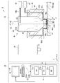
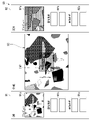
- FIG. 1 is a schematic configuration diagram schematically showing a microscope system of one embodiment, and is a diagram showing a case where an object can be imaged by an optical microscope.
- FIG. 2 is a schematic configuration diagram schematically showing a microscope system of one embodiment, and is a diagram showing a case where an object can be imaged by an electron microscope.
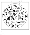
- FIG. 3 is a diagram showing an example of an object observed by the microscope system of one embodiment.
- FIG. 4 is a diagram showing a selection screen of one embodiment.
- FIG. 5 is a diagram showing an observation screen of an optical microscope according to an embodiment.
- FIG. 6 is a screen showing an observation screen of an electron microscope according to an embodiment.
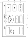
- FIG. 7 is a diagram showing a state in which the observation screen and the navigation screen of the electron microscope of one embodiment are displayed side by side.
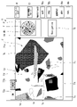
- FIG. 8 is a diagram showing a composite screen of one embodiment.
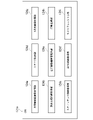
- FIG. 9 is a flowchart showing an example of a procedure performed by the user in the automatic imaging mode of one embodiment.
- FIG. 10 is a flowchart showing an example of the procedure of the calibration step of one embodiment.
- FIG. 11 is a diagram for explaining the XY calibration process of one embodiment.
- FIG. 12 is a diagram for explaining a coordinate axis correction step of one embodiment.
- FIG. 13 is a flowchart showing an example of the procedure of the control method of one embodiment.
- FIG. 14 is a schematic diagram showing a functional unit of a CPU in a modified example of the embodiment.
- the XYZ Cartesian coordinate system is appropriately shown in the drawings, and the positional relationship of each part will be described with reference to this XYZ Cartesian coordinate system.
- the direction parallel to the X axis is described as "first horizontal direction X”
- the direction parallel to the Y axis is described as “second horizontal direction Y”
- the direction parallel to the Z axis is described as “vertical direction Z”. do.
- the first horizontal direction X, the second horizontal direction Y, and the vertical direction Z are directions orthogonal to each other.
- the positive side (+ Z side) of the vertical direction Z facing the Z-axis arrow is described as “upper” or “upper side”, and the negative side of the vertical direction Z opposite to the side facing the Z-axis arrow (+ Z side).
- -Z side is described as "lower side” or “lower side”.
- the vertical direction Z is the height direction.
- the microscope system 1 includes a microscope device 10 and a control unit 20.
- the microscope device 10 is arranged, for example, in atmospheric pressure.
- the microscope device 10 includes an optical microscope (optical device) 30, an electron microscope 40, and a stage 50.
- the optical microscope 30 and the electron microscope 40 are arranged side by side in the first horizontal direction X, for example.
- the electron microscope 40 is arranged, for example, on the right side of the optical microscope 30.
- the type of the optical microscope 30 is not particularly limited.
- the optical microscope 30 may be, for example, a bright-field microscope, a dark-field microscope, a fluorescent microscope, a differential interference microscope, or these microscopes. It may be an appropriate combination of microscopes.
- the optical microscope 30 may have any structure as long as it can acquire the focus information of the object J.
- the optical microscope 30 has a lens 31 facing downward. As shown in FIG. 1, the optical microscope 30 irradiates light L downward from the lens 31 toward the object J on the stage 50 to image the object J.
- the optical axis direction of the light L and the vertical direction Z are substantially parallel.
- the light source that irradiates the light L is not particularly limited.
- the distance Z in the vertical direction from the upper surface 50a of the stage 50 to the lens 31 is expressed as the height H of the lens 31.
- the height H of the lens 31 is the lens (final lens or final optical system) closest to the object J among the plurality of lenses 31 from the upper surface 50a of the stage 50. It is the distance Z in the vertical direction to 31).
- the type of the electron microscope 40 is not particularly limited.
- the electron microscope 40 is, for example, a scanning electron microscope (SEM).
- the electron microscope 40 may be a transmission electron microscope (Transmission Electron Microscope; TEM).
- the electron microscope 40 includes a housing 41, a light source unit 42, a photoelectric unit 43, an electronic lens 44, and an exhaust device 45.
- the housing 41 has, for example, a cylindrical shape extending in the vertical direction Z. Inside the housing 41, an electron beam path 41a through which the electron beam EB passes is provided. The optical axis direction of the electron beam EB and the vertical direction Z are substantially parallel. The electron beam path 41a extends in the vertical direction Z. A photoelectric portion 43 is provided at the upper end of the electron beam path 41a. An injection hole 41c facing downward is provided at the lower end of the housing 41.
- the light source unit 42 is fixed to the upper end surface of the housing 41.
- the light source unit 42 can emit light into the internal space of the housing 41.
- the light emitted from the light source unit 42 into the internal space of the housing 41 is applied to the photoelectric unit 43 provided in the housing 41.
- the photoelectric unit 43 emits an electron beam EB by being irradiated with light due to the photoelectric effect. As shown in FIG. 2, in the present embodiment, the photoelectric unit 43 emits an electron beam EB downward when the light of the light source unit 42 is incident from above. The electron beam EB emitted downward from the photoelectric portion 43 is emitted downward from the emission hole 41c toward the object J through the electron beam path 41a.
- the electronic lens 44 is arranged inside the housing 41.
- the electron lens 44 is arranged below the photoelectric portion 43 so as to surround the electron beam path 41a.
- the electron lens 44 converges the electron beam EB emitted from the photoelectric unit 43 and guides it to the emission hole 41c.
- the electronic lens 44 is a magnetic field lens using a permanent magnet.
- the electronic lens 44 may be a magnetic field lens that does not use a permanent magnet, or may be an electrostatic lens.
- the acceleration voltage applied to the electron beam EB is a voltage applied between the extraction electrode (not shown) arranged below the photoelectric portion 43 in the housing 41 and the photoelectric portion 43.
- the larger the acceleration voltage the lower the focal position of the electron microscope 40. In other words, the larger the acceleration voltage, the deeper the depth of focus of the electron microscope 40.
- the exhaust device 45 includes a nozzle member 46, a first pump 47, and a second pump 48.
- the nozzle member 46 is an annular shape that surrounds the housing 41 around the central axis AX of the electron microscope 40.
- the central axis AX is a virtual line extending in the vertical direction Z. In the present embodiment, the central axis AX passes through the center of the electron beam path 41a.
- the nozzle member 46 has a protruding portion 46a that protrudes downward.
- the protrusion 46a surrounds the lower end surface 41b of the housing 41 around the central axis AX.
- the nozzle member 46 is provided with a first intake flow path 49a.
- a plurality of first intake flow paths 49a are provided, for example.
- the first intake flow path 49a has an intake port 49c that opens to the lower end surface 46b of the protrusion 46a.
- the intake ports 49c in the plurality of first intake flow paths 49a are arranged, for example, on the lower end surface of the protrusion 46a at intervals in the circumferential direction around the central axis AX.
- the first pump 47 and the second pump 48 are vacuum pumps.
- the type of the vacuum pump used as the first pump 47 and the second pump 48 is not particularly limited.
- the first pump 47 is, for example, an oil diffusion pump.
- the second pump 48 is, for example, a pump in which an oil diffusion pump and a turbo molecular pump are combined.
- the first pump 47 is connected to the first intake flow path 49a. Air is sucked into the first intake flow path 49a from the intake port 49c by the first pump 47. As a result, the air between the lower end surface of the protrusion 46a and the stage 50 is sucked into the first intake flow path 49a. At least a part of the air inside the protrusion 46a may be sucked into the first intake flow path 49a.
- the second pump 48 can suck the air in the electron beam path 41a via the second intake flow path 49b.
- the second intake flow path 49b is connected to, for example, the upper end portion in the electron beam path 41a.
- the air in the electron beam path 41a is sucked into the second intake flow path 49b.
- At least a part of the air inside the protrusion 46a may be sucked into the second intake flow path 49b.
- the microscope system 1 can form a local vacuum region G between the object J arranged on the stage 50 and the electron microscope 40.
- the stage 50 is movable below the optical microscope 30 and the electron microscope 40.
- the stage 50 can be moved in each of the first horizontal direction X and the second horizontal direction Y, for example.
- the stage 50 has an upper surface 50a facing upward.
- An object J can be arranged on the upper surface 50a.
- the upper surface 50a is provided with a holding recess 51 that is recessed downward.
- a plate P on which the object J is placed is fitted in the holding recess 51 so that the object J can be held.
- the object J can be arranged on the upper surface 50a of the stage 50 via the plate P.
- the stage 50 may be movable in the vertical direction Z.
- the control unit 20 includes a control device 21, an output unit 22, and an input unit 23.
- the control device 21 is, for example, a PC (personal computer).
- the control device 21 controls the microscope device 10. Specifically, the control device 21 controls the optical microscope 30, the electron microscope 40, and the stage 50. That is, the control unit 20 can control the optical microscope 30, the electron microscope 40, and the stage 50.
- the control device 21 has a CPU (Central Processing Unit) 21a, a ROM (Read Only Memory) 21b, and a RAM (Random access memory) 21c.
- the CPU 21a is a part that performs each control and each process.
- the ROM 21b and the RAM 21c are storage units for storing information (also referred to as storage, storage, etc.).
- the control unit 20 may be a tablet PC in which the control device 21, the output unit 22, and the input unit 23 are integrated.
- storing storing, storing
- it is intended to be stored (saved, stored) in the ROM 21b or RAM 21c.
- the output unit 22 and the input unit 23 are connected to the control device 21 by wire or wirelessly.
- the output unit 22 is, for example, a display device such as a liquid crystal display.
- the output unit 22 is arranged with a display area 100 on which a screen (Graphical User Interface; GUI) for controlling the microscope device 10 is displayed based on the signal output from the control device 21.
- GUI Graphic User Interface
- a screen for controlling the microscope device 10 by activating an information processing program for controlling the microscope device 10 by the CPU 21a is displayed in the display area 100 of the output unit 22.
- the information processing program is installed in the control device 21 in advance, for example. For the sake of simplicity, even when it is intended to "display in the display area 100 of the output unit 22," it may be simply described as "display” or the like.
- the input unit 23 includes, for example, a keyboard 23a and a mouse 23b.
- a signal is input from the input unit 23 to the control device 21.
- the user can control the microscope system 1 via the screen displayed in the display area 100 of the output unit 22, for example, by using the input unit 23.
- the output unit 22 may be provided with a touch panel or the like that functions as an input unit. In that case, when the user operates the output unit 22, a signal is input from the output unit 22 to the control device 21. Specifically, the user can control the microscope system 1 via the screen displayed in the display area 100 of the output unit 22, for example, by using the output unit 22.
- FIG. 3 is a diagram showing an example of an object J observed by the microscope system 1.
- the plurality of objects T include objects T having different sizes, objects T having different shapes, objects T having different colors, and objects T having different materials.
- FIG. 4 is a diagram showing a selection screen 60 displayed in the display area 100 of the output unit 22 of the present embodiment.
- FIG. 5 is a diagram showing an observation screen (OM observation screen) 71 of the optical microscope 30 displayed in the display area 100 of the output unit 22 of the present embodiment.
- FIG. 6 is a screen showing an observation screen 72 of the electron microscope 40 displayed in the display area 100 of the output unit 22 of the present embodiment.
- FIG. 7 is a diagram showing a state in which the observation screen (SEM observation screen) 72 of the electron microscope 40 displayed in the display area 100 of the output unit 22 of the present embodiment and the navigation screen 80 are displayed side by side.
- FIG. 8 is a diagram showing a composite screen 90 displayed in the display area 100 of the output unit 22 of the present embodiment.
- the screens displayed in the display area 100 of the output unit 22 include the selection screen 60, the OM observation screen (first screen) 71, and the SEM observation screen (first screen).
- the selection screen 60 shown in FIG. 4 is, for example, a screen that is first displayed in the display area 100 when the information processing program for controlling the microscope device 10 is started by the control device 21.
- the control device 21 displays the display selection area 60a, the stage control area 60b, and the exhaust control area 60c in the display area 100 as the selection screen 60.
- the display selection area 60a is arranged in the area on the right side of the selection screen 60, for example, on the paper of FIG.
- the stage control area 60b is arranged in the central area of the selection screen 60, for example, on the paper of FIG.
- the exhaust control region 60c is arranged in the left region of the selection screen 60, for example, on the paper of FIG.
- An OM icon (first display icon) 61, an SEM icon (second display icon) 62, and a utility icon 63 are arranged in the display selection area 60a.
- the OM icon 61, the SEM icon 62, and the utility icon 63 are arranged side by side in this order from top to bottom on the selection screen 60, for example, on the paper of FIG.
- the character "OM” is displayed on the OM icon 61.
- the characters "SEM” are displayed on the SEM icon 62.
- the characters "Image Utility" are displayed on the utility icon 63.
- the "icon” in the present specification is an image associated with a file or a program (typically, a computer program that can be executed by the CPU 21a) registered in the control device 21 in advance.
- the user can use each icon to start a desired program.
- the user can control the microscope system 1 by using each icon.
- the control device 21 activates a program associated with the icon.
- the control device 21 causes the microscope system 1 to perform the process associated with the icon.
- the user can display the OM observation screen 71 shown in FIG. 5 by selecting the OM icon 61 by operating the mouse 23b, for example. That is, the OM icon 61 corresponds to the first display icon that displays the OM observation screen 71.
- the user can display the SEM observation screen 72 shown in FIG. 6 by selecting the SEM icon 62 by operating the mouse 23b. That is, the SEM icon 62 corresponds to the second display icon that displays the SEM observation screen 72.
- the user can display the composite screen 90 shown in FIG. 8 by selecting the utility icon 63 by operating the mouse 23b, for example. That is, the utility icon 63 corresponds to an icon that displays the composite screen 90.
- the stage position display 64 is displayed in the stage control area 60b.
- the stage position display 64 is arranged, for example, on the paper surface of FIG. 4 in the upper portion of the stage control area 60b.
- the stage position display 64 displays the position of the stage 50 in the microscope device 10.
- the stage position display 64 has a stage marker 64a and a marker guide 64b.
- the marker guide 64b is, for example, a triangular frame line that is convex downward on the paper surface of FIG. 4.
- the position of the left corner of the corner of the marker guide 64b is the OM observation position PS1.
- the position of the right corner of the corner of the marker guide 64b is the SEM observation position PS2.
- the position of the lower center corner of the corners of the marker guide 64b is the object exchange position PS3.
- the control device 21 moves the stage marker 64a on the marker guide 64b according to the movement of the stage 50.
- the stage marker 64a is displayed, for example, at the object exchange position PS3.
- the control device 21 When the stage 50 is in a position where the object J can be observed by the optical microscope 30 (that is, the position shown in FIG. 1), the control device 21 displays the stage marker 64a at the OM observation position PS1. When the stage 50 is in a position where the object J can be observed by the electron microscope 40 (that is, the position shown in FIG. 2), the control device 21 displays the stage marker 64a at the SEM observation position PS2. When the stage 50 is in a position where the object J on the stage 50 can be exchanged by the user, the control device 21 displays the stage marker 64a at the object exchange position PS3.
- the position where the stage 50 can exchange the object J on the stage 50 by the user is, for example, a position not located below the optical microscope 30 or below the electron microscope 40.
- the control unit 20 outputs the stage position display 64 to the output unit 22 as information indicating the relative position between the stage 50 and the optical microscope 30 or the relative position between the stage 50 and the electron microscope 40. It can be displayed.
- the user can exchange the object J on the stage 50 means that the user can exchange the object J on the stage 50 directly or indirectly by using another transport device or the like. All you need is.
- the take-out icon 65 and the reset icon 66 are arranged in the stage control area 60b.
- the take-out icon 65 and the reset icon 66 are arranged below the stage position display 64.
- the characters "Eject” are displayed on the eject icon 65.
- the characters "Stage Reset” are displayed on the reset icon 66.
- the take-out icon 65 is an icon that moves the stage 50 to a position where the user can exchange the object J.
- the user can move the stage 50 to a position where the object J can be exchanged by selecting the take-out icon 65 by operating the mouse 23b. That is, when the control device 21 detects that the take-out icon 65 is selected by the mouse 23b, the control device 21 controls a movement mechanism (not shown) to move the stage 50 to a position where the user can exchange the object J.
- the reset icon 66 is arranged below the take-out icon 65, for example, on the paper of FIG.
- the reset icon 66 is an icon that returns the position of the stage 50 to the initial position.
- the initial position includes an initial position at a position where the object J can be observed by the optical microscope 30 and an initial position at a position where the object J can be observed by the electron microscope 40.
- the user can set the stage 50 at the initial position among the positions where the object J can be observed by the optical microscope 30, or the object J by the electron microscope 40. It can be moved to the initial position among the observable positions.
- the stage 50 is the initial position in which the object J can be observed by the optical microscope 30. Move to position.
- the stage 50 is the initial position in which the object J can be observed by the electron microscope 40. Move to position.
- the atmospheric pressure display 67 is displayed in the exhaust control area 60c.
- the atmospheric pressure display 67 is displayed on the upper portion in the exhaust control region 60c.
- the atmospheric pressure display 67 displays the atmospheric pressure in the electron microscope 40.
- the characters "Vacuum State” are labeled below the atmospheric pressure display 67.
- the air pressure in the electron microscope 40 includes the air pressure in the electron beam path 41a, the air pressure in the protrusion 46a, and the air pressure between the electron microscope 40 and the stage 50.
- the air pressure in the electron microscope 40 includes the air pressure in the local vacuum region G between the object J arranged on the stage 50 and the electron microscope 40.
- the intake start icon 68 is arranged in the exhaust control area 60c. In the paper of FIG. 4, the intake start icon 68 is arranged below the barometric pressure display 67. For example, the characters "Vacuum Start” are displayed on the intake start icon 68.
- the intake start icon 68 is an icon for starting intake by the exhaust device 45 of the electron microscope 40. For example, the user can start the intake by the exhaust device 45 by selecting the intake start icon 68 by operating the mouse 23b, and create a local vacuum region G between the stage 50 and the electron microscope 40. Can be done.
- the OM observation screen 71 shown in FIG. 5 corresponds to the first screen in which the object J is imaged and displayed by the optical microscope 30.
- the SEM observation screen 72 shown in FIG. 6 corresponds to a second screen in which the object J is imaged and displayed by the electron microscope 40.
- the stage 50 is arranged at a position where the object J can be imaged by the optical microscope 30.
- the stage 50 is arranged at a position where the object J can be imaged by the electron microscope 40.
- the control device 21 displays switching icons 73a and 73b for switching to the other screen on the OM observation screen 71 and the SEM observation screen 72, respectively.
- the switching icon 73a is an icon for switching the SEM observation screen 72 to the OM observation screen 71.
- the switching icon 73b is an icon for switching the OM observation screen 71 to the SEM observation screen 72.
- the switching icon 73a and the switching icon 73b are displayed on both the OM observation screen 71 and the SEM observation screen 72.
- the switching icon 73a and the switching icon 73b are arranged side by side in the left-right direction on the upper left of the first display units 71a and 72a, which will be described later.
- the character "OM” is displayed on the switching icon 73a.
- the characters "SEM" are displayed on the switching icon 73b.
- the switching icon 73a is displayed brightly and the switching icon 73b is displayed dark on the OM observation screen 71.
- “Bright” means a state in which the amount of light in the display area 100 is large and the user can clearly see it visually.
- the “dark” means a state in which the amount of light in the display area 100 is small and the user cannot visually clearly see it.
- the characters "OM" displayed on the switching icon 73a are highlighted. On the OM observation screen 71, the switching icon 73a does not work.
- the user can switch the screen from the OM observation screen 71 to the SEM observation screen 72 by selecting, for example, the switching icon 73b displayed on the OM observation screen 71 by operating the mouse 23b.
- the control device 21 moves the stage 50 from a position where the object J can be imaged by the optical microscope 30 to a position where the object J can be imaged by the electron microscope 40. Let me.
- the switching icon 73b is displayed brightly, and the switching icon 73a is displayed darkly.
- the characters "SEM" displayed on the switching icon 73b are highlighted, and the screen currently displayed is the SEM observation screen 72 of the OM observation screen 71 and the SEM observation screen 72. Shown.
- the switching icon 73b does not work.
- the user can switch the screen from the SEM observation screen 72 to the OM observation screen 71 by selecting, for example, the switching icon 73a displayed on the SEM observation screen 72 by operating the mouse 23b.
- the control device 21 moves the stage 50 from a position where the object J can be imaged by the electron microscope 40 to a position where the object J can be imaged by the optical microscope 30. Let me.
- the control device 21 displays the first display unit 71a as a part of the OM observation screen 71.
- the control device 21 displays the first display unit 72a as a part of the SEM observation screen 72.
- the first display units 71a and 72a are display units that display real-time images of the object J, respectively.
- the real-time image is not an image captured in the past, but an image captured in the present progressive tense.
- the first display unit 71a displays a real-time image of the object J captured by the optical microscope 30.
- the first display unit 72a displays a real-time image of the object J captured by the electron microscope 40.
- the control unit 20 can display the image captured by the optical microscope 30 and the image captured by the electron microscope 40 on the output unit 22.
- Each of the first display units 71a and 72a is the portion displayed in the largest size on each observation screen.
- the OM observation screen 71 and the SEM observation screen 72 are different from each other in that the display unit for displaying the object J is different between the first display unit 71a and the first display unit 72a, and the above-mentioned switching icons 73a and 73b. It is a similar screen except that the display of is different.
- the first display unit 71a is switched to the first display unit 72a.
- the first display unit 72a is switched to the first display unit 71a.
- control unit 20 can switch between the display of the image captured by the optical microscope 30 and the display of the image captured by the electron microscope 40 by switching the screen based on the operation by the user.
- control unit 20 can switch between displaying a real-time image captured by the optical microscope 30 and displaying a real-time image captured by the electron microscope 40.
- the center position of the image (real-time image) displayed on the first display units 71a and 72a, which is switched when the switching icons 73a and 73b are selected reflects the same location on the same object J.
- the image magnification of the optical microscope 30 and the image magnification of the electron microscope 40 are the same as in the examples of FIGS. 5 and 6, the first display unit 71a, which is switched when the switching icons 73a and 73b are selected.
- the image (real-time image) reflected on 72a is, for example, an image (real-time image) of the same range in the same object J.
- the imaging magnification of the optical microscope 30 and the imaging magnification of the electron microscope 40 are the same, when the screen is switched from the OM observation screen 71 to the SEM observation screen 72, the first display unit 71a on the OM observation screen 71 An image (real-time image) captured by the electron microscope 40 in the same range as the range of the object J displayed on the SEM observation screen 72 is displayed on the first display unit 72a of the SEM observation screen 72.
- an image captured by the optical microscope 30 in the same range as the range of the object J displayed on the first display unit 72a on the SEM observation screen 72 when the screen is switched from the SEM observation screen 72 to the OM observation screen 71, an image captured by the optical microscope 30 in the same range as the range of the object J displayed on the first display unit 72a on the SEM observation screen 72.
- (Real-time image) is displayed on the first display unit 71a of the OM observation screen 71.
- the real-time image captured by the optical microscope 30 switched to each other and the real-time image captured by the electron microscope 40 include images in the same range in the same object J.
- the imaging magnification of the electron microscope 40 is larger than the imaging magnification of the optical microscope 30
- the screen is switched from the OM observation screen 71 to the SEM observation screen 72
- the OM observation screen 71 is displayed on the first display unit 72a.
- An enlarged image of the central portion of the image displayed on the first display unit 71a of the above is displayed.
- the real-time image captured by the optical microscope 30 is switched to the real-time image captured by the electronic microscope 40, the real-time image after the switching is the optical microscope 30 before the switching. It is included that it is an enlarged image of a part of the range of the object J projected on the image captured by.
- the image of the object J displayed on the first display unit 71a of the OM observation screen 71 contains information on the color of the object J.
- the image of the object J reflected on the first display unit 71a is a color image.
- the objects Ta to Te having different colors are displayed on the first display unit 71a.
- the image of the object J displayed on the first display unit 72a of the SEM observation screen 72 is information about the material of the object J and the height direction (vertical direction Z) of the object J. Contains information about the uneven shape of.
- the image of the object J reflected on the first display unit 72a is a monochrome image.
- the black object T1 and the white object T2 are displayed on the first display unit 72a.
- an element having a relatively small mass such as carbon tends to appear black
- an element having a relatively large mass such as metal tends to appear white.
- the black-and-white color information indicates the information of the material of the object J.
- the black object T1 is a non-metal such as carbon
- the white object T2 is a metal.
- the image of the object J displayed on the first display unit 71a of the OM observation screen 71 is, for example, the optics of the object J captured by the optical microscope 30 in a state where the focus is adjusted by the autofocus function of the optical microscope 30. It is a microscope image.
- This light microscope image may be an image in which a part of the displayed area is in focus (focused), or an image in which all of the displayed area is in focus (). It may be an omnidirectional image). Examples of the omnifocal image include a depth composite image IM1a described later.
- the image of the object J displayed on the first display unit 72a of the SEM observation screen 72 is, for example, an electron microscope 40 in a state where the focus is adjusted based on the information of the object J obtained from the optical microscope 30. It is an electron microscope image of the object J imaged by.
- This electron microscope image is an image that is in focus (focused). That is, the image captured by the electron microscope 40 in the present embodiment includes an image captured by adjusting the focus of the electron microscope 40 based on the information obtained from the optical microscope 30.
- the focus adjusting method of the present embodiment includes adjusting the focus of the electron microscope 40 based on the information of the object J obtained from the optical microscope 30.
- the information of the object J obtained from the optical microscope 30 includes the focus information (focus information) of the object J to be imaged.
- the focus information of the object J is information on the position of the object J in the vertical direction Z from a certain reference position, and is necessary for focusing on a portion of the object J located at a certain height. Includes information and more.
- the focal information required to focus on a portion of the object J located at a certain height includes the height H of the lens 31 of the optical microscope 30 with respect to the upper surface 50a of the stage 50.
- the control unit 20 acquires, for example, the height H of the lens 31 capable of focusing on a predetermined object J with an optical microscope 30 as information related to the height of the object J.
- the control unit 20 acquires in advance the relationship between the height H of the lens 31 and the acceleration voltage applied to the electron beam EB by the Z calibration step Sc2 described later.
- the control unit 20 can focus the electron microscope 40 on the portion of the object J that the optical microscope 30 focuses on when the height H of the lens 31 is a certain value. The value of can be calculated. Therefore, when the optical microscope 30 and the electron microscope 40 image the same part of the same object J, the lens 31 required to first image the part with the optical microscope 30 and focus the optical microscope 30.
- the acceleration voltage can be calculated from the height H and the electron microscope 40 can be focused on the portion. That is, it is not necessary to adjust the focus while imaging the object J with the electron microscope 40 as in the conventional case, and by applying the calculated acceleration voltage and emitting the electron beam EB, the image is captured by the electron microscope 40. You can capture a focused image from the moment you start.
- the relationship between the height H of the lens 31 and the acceleration voltage applied to the electron beam EB is, for example, linear.
- the relationship between the height H of the lens 31 and the acceleration voltage applied to the electron beam EB is stored in, for example, ROM 21b or RAM 21c. Then, when the focus is controlled by the electron microscope 40 or the optical microscope 30, the relationship between the height H of the lens 31 and the acceleration voltage applied to the electron beam EB is used.
- control unit 20 is related to the height of the object J based on the relationship between the acceleration voltage in the electron microscope 40 and the information related to the height of the object J obtained from the optical microscope 30.
- the focus of the electron microscope 40 can be adjusted by calculating the value of the acceleration voltage of the electron microscope 40 from the information and adjusting the acceleration voltage of the electron microscope 40 to the calculated value.
- the focus of the electron microscope 40 can be adjusted based on the image pickup result of the optical microscope 30. Therefore, if the object J is first imaged by the optical microscope 30, when the SEM observation screen 72 is displayed, the electron microscope image focused from the beginning can be displayed on the first display unit 72a. As described above, in the present embodiment, when the real-time image captured by the optical microscope 30 is switched to the real-time image captured by the electron microscope 40, the real-time image after the switching is displayed from the time when the display is started. The image includes that the focus of the electron microscope 40 is adjusted to obtain an image.
- the control unit 20 takes an image of the entire object J with an optical microscope 30 and obtains the focus information of the imaged object J. You may get it. In this case, even if the SEM observation screen 72 is displayed before the OM observation screen 71, the information acquired in advance by the optical microscope 30 is used to initially display the SEM observation screen 72 on the first display unit 72a. It is possible to display a real-time image captured by the electron microscope 40 in a focused state.
- the user selects and selects a part of the optical microscope image displayed on the first display unit 71a of the OM observation screen 71 by operating the mouse 23b, so that the image is displayed on the first display unit 71a.
- the optical microscope image to be obtained can be switched to an image in which the object J is imaged centering on the portion of the object J corresponding to a part of the selected optical microscope image.
- the user selects and selects a part of the electron microscope image displayed on the first display unit 72a of the SEM observation screen 72 by operating the mouse 23b, so that the image is displayed on the first display unit 72a.
- the electron microscope image to be obtained can be switched to an image in which the object J is imaged centering on the portion of the object J corresponding to a part of the selected electron microscope image.
- the control device 21 displays the second display unit 74 as a part of the OM observation screen 71 and the SEM observation screen 72.
- the second display unit 74 is a display unit that displays the entire image of the object J.
- the second display unit 74 is displayed on the right side of the first display units 71a and 72a on the OM observation screen 71 and the SEM observation screen 72, respectively.
- the second display unit 74 is smaller than the first display units 71a and 72a.
- the second display unit 74 displays an image showing the entire object J and the entire plate P on which the object J is placed.
- the image displayed on the second display unit 74 is not a real-time image, but an image captured before each observation screen is displayed.
- the image displayed on the second display unit 74 may be an image captured by the optical microscope 30, an image captured by the electron microscope 40, or an image IM1 described later. Alternatively, it may be the image IM2 described later.
- a mark M1 indicating the position of the range of the object J reflected in the real-time image displayed on the first display units 71a and 72a is displayed.
- the mark M1 is a cross-shaped mark.
- the portion of the object J corresponding to a predetermined range centered on the position where the centers of the cross-shaped marks M1 overlap is displayed on the first display units 71a and 72a in real time. Is displayed.
- the range of the object J displayed on the first display units 71a and 72a changes depending on the imaging magnification of each microscope. 5 and 6 show a case where, for example, the imaging magnification of the optical microscope 30 and the imaging magnification of the electron microscope 40 are the same, and the same range of the object J is imaged.
- the user selects a part of the entire image of the object J displayed on the second display unit 74, so that the real-time image displayed on the first display units 71a and 72a is displayed in the second display. It is possible to switch to a real-time image that captures the range of the object J corresponding to a part of the image selected on the unit 74.
- the portion of the object J corresponding to the selected portion is the first display unit.
- the stage 50 moves so as to be reflected at the center position of the images displayed on 71a and 72a.
- the portion of the object J corresponding to the portion selected on the image displayed on the second display unit 74 can be projected on the first display units 71a and 72a.
- the mark M1 moves to a position selected by the user on the image displayed on the second display unit 74.
- the image displayed on the second display unit 74 includes the focus information of the object J described above, or when the focus information of the object J is associated with the image, the image is displayed on the second display unit 74.
- the real-time image displayed on the first display unit 72a of the SEM observation screen 72 can be made into a focused image from the beginning.
- the case where the image displayed on the second display unit 74 includes the focus information of the object J described above and the case where the focus information of the object J is associated are displayed on the second display unit 74, for example. This includes the case where the image is the depth composite image IM1a described later.
- the control device 21 displays the navigation icon 75 as a part of the OM observation screen 71 and the SEM observation screen 72.
- the characters "Navigation" are displayed on the navigation icon 75.
- the navigation icon 75 is an icon for displaying the navigation screen 80 shown in FIG. 7.
- the navigation icon 75 is arranged below the second display unit 74 on each observation screen.
- the user can display the navigation screen (first acquisition screen) 80 shown in FIG. 7, for example, by selecting the navigation icon 75 by operating the mouse 23b.
- the navigation screen 80 can be displayed at the same time as the observation screen of either the OM observation screen 71 or the SEM observation screen 72.
- FIG. 7 shows a case where the navigation screen 80 is displayed at the same time as the SEM observation screen 72.
- the characters "Navigation" are displayed on the upper left of the navigation screen 80.
- the navigation screen 80 is a first acquisition screen for acquiring an image IM1 obtained based on a plurality of images captured by the optical microscope 30. In this way, the control unit 20 can display the navigation screen 80 on the output unit 22 as the first acquisition screen for acquiring the image IM1.
- the image IM1 includes a depth composite image (first image, second image, composite image) IM1a and a stitching image IM1b.
- the expression “acquire an image” is synonymous with “generate an image”, “create an image”, and the like.
- Depth composite image IM1a is an image created by depth compositing a plurality of images.
- the depth composite image IM1a is a plurality of optical microscope images acquired by imaging the object J a plurality of times with different positional relationships between the focal position and the object in the vertical direction Z by the optical microscope 30. Is made by depth synthesis.
- the depth composite image IM1a is a focused pixel information (focused pixel information) in a plurality of optical microscope images acquired by imaging the object J multiple times with different positional relationships between the focal position and the object in the vertical direction Z. It is a composite image composed of (simply also referred to as pixels).
- the depth composite image IM1a is an image formed by focused pixels obtained from a plurality of images having different positional relationships between the focal position and the object in the vertical direction Z. Further, the depth composite image IM1a is a omnifocal image in which the entire range of the object J reflected in the image is in focus.
- each of the plurality of pixels constituting the depth composite image IM1a includes the focus information for the object J.
- the pixel includes color information (color tone and gradation) when the control device 21 handles an image.
- the plurality of pixels constituting the depth composite image IM1a include focus information at the portion of the object J corresponding to the position of each pixel.
- this focal information is information indicating the positional relationship between the focal position and the object in the vertical direction.
- the focus information is information indicating that "it is the Xth image in the Z direction”.
- the focal information is information indicating "the value of the height H of the lens 31".
- the value of the height H of the lens 31 is information indicating at which focal position the optical microscope image was captured. Therefore, appropriate focus information can be acquired from each of the plurality of pixels of the depth composite image IM1a.
- the plurality of pixels constituting the depth composite image IM1a may not directly include the focal information but may be associated with the focal information included in the focal table stored in the ROM 21b or the RAM 21c. Even in this case, the value of the height H of the lens 31 associated with the plurality of pixels of the depth composite image IM1a can be acquired from the ROM 21b or the RAM 21c.
- the focus table is data in which the pixel positions of the depth composite image and the focus information are associated with each other.
- the stitching image IM1b is an image created by joining a plurality of images at different positions on the XY plane (horizontal plane).
- the stitching image IM1b is an image created by joining nine optical microscope images of three rows and three columns captured by an optical microscope 30.
- the nine optical microscope images constituting the stitching image IM1b in the present embodiment are the depth composite image IM1a.
- the control device 21 displays the third display unit 85 on which the image IM1 is displayed as a part of the navigation screen 80.
- the stitching image IM1b is displayed on the third display unit 85.
- the navigation screen 80 for example, the image is not displayed on the third display unit 85.
- the acquired image IM1 is displayed on the third display unit 85.
- a mode selection field 81 On the navigation screen 80, a mode selection field 81, an image pickup range designation field 82, and an image pickup start icon 83 are arranged.
- the mode selection field 81, the image pickup range designation field 82, and the image pickup start icon 83 are arranged side by side in this order from the upper side to the lower side on the right side of the third display unit 85.
- the characters "mode” are displayed on the upper side of the mode selection field 81.
- the characters "imaging range designation" are displayed on the upper side of the imaging range designation field 82.
- the character "imaging" is displayed on the imaging start icon 83.
- the mode selection field 81 is a field for selecting a mode for acquiring the image IM1.
- the mode selection field 81 is, for example, a drop-down list in which a value (character or the like) indicating a selectable mode is input.
- the user can select one mode in the mode selection field 81, for example, by operating the mouse 23b.
- the modes that can be selected in the mode selection field 81 include a depth synthesis mode and a non-depth synthesis mode.
- the depth composition mode is a mode for acquiring an image IM1 using depth composition.
- the non-depth composition mode is a mode for acquiring an image IM1 without using depth composition.
- the character "Focus Stacking" displayed in the mode selection field 81 indicates that the depth stacking mode is selected as the mode for acquiring the image IM1.
- the image pickup range designation column 82 is a column for designating the image pickup range required for acquiring the image IM1.
- the image pickup range designation field 82 is, for example, a drop-down list in which a value (character or the like) indicating a selectable image pickup range is input.
- the user can specify one imaging range in the imaging range designation field 82, for example, by operating the mouse 23b.
- the imaging range that can be specified in the imaging range designation field 82 is the range of the object J that can be imaged by one imaging by the optical microscope 30, and the range of the object J that can be imaged by imaging at a plurality of different points. ,including.
- the character "3 ⁇ 3" displayed in the imaging range designation column 82 is an object that can be imaged as a whole by imaging at 9 locations arranged in 3 rows and 3 columns as an imaging range. Indicates that the range of the object J is specified. At this time, the center position of the object J in the center portion CF of the nine locations corresponds to the center position of the image displayed on the first display unit 72a on the SEM observation screen 72 displayed at the same time as the navigation screen 80. Is.
- the imaging range that can be specified in the imaging range designation field 82 is an object corresponding to the image displayed on the first display units 71a and 72a of the OM observation screen 71 or the SEM observation screen 72 displayed at the same time as the navigation screen 80. Includes a predetermined range centered on the position of the object J.
- the control unit 20 can specify the range of the object J for acquiring the image IM1 on the navigation screen 80 as the first acquisition screen.
- FIG. 7 shows a state in which the portion of the object J displayed on the first display unit 72a of the SEM observation screen 72 is changed after the image IM1 is acquired. Therefore, in FIG. 7, the center position of the object J with respect to the center position of the image IM1 displayed on the third display unit 85 of the navigation screen 80 is the electron microscope image displayed on the first display unit 72a of the SEM observation screen 72. It is different from the center position of the object J with respect to the center position of.
- the image pickup start icon 83 is an icon for starting the acquisition of the image IM1. For example, by selecting the image pickup start icon 83 by operating the mouse 23b, the user can acquire the image IM1 based on the mode selected in the mode selection field 81 and the image pickup range selected in the image pickup range designation field 82. can.
- the control unit 20 uses the optical microscope 30 to make a plurality of optical microscopes having different focal positions at each of the nine locations of the designated vertical and horizontal 3 rows and 3 columns. Get an image.
- the control unit 20 acquires the focal information (for example, the height H of the lens 31) for each part of the object J by the optical microscope 30.
- the control unit 20 depth-synthesizes the acquired plurality of optical microscope images, and acquires a plurality of depth-combined images IM1a corresponding to each of the captured portions.
- the control unit 20 acquires the stitching image IM1b by connecting a plurality of the acquired depth composite images IM1a and displays them on the third display unit 85. In this way, in the present embodiment, the control unit 20 can display the image IM1 obtained based on the plurality of images captured by the optical microscope 30.
- the user By selecting a part of the image IM1 displayed on the third display unit 85 of the navigation screen 80, the user selects the first display unit 71a on the OM observation screen 71 or the SEM observation screen 72 displayed at the same time as the navigation screen 80. , 72a can be changed to an image that captures the portion of the object J corresponding to the portion selected in the image IM1.
- the user can select a part of the image IM1 by, for example, selecting a part of the image IM1 displayed on the third display unit 85 by operating the mouse 23b.
- a real-time image in which a predetermined range centered on the part of the object J corresponding to the selected part of the image IM1 is captured is displayed at the same time as the navigation screen 80. It is displayed on the first display units 71a and 72a of the observation screen.
- the image IM1 displayed on the third display unit 85 of the navigation screen 80 is an optical microscope image captured by the optical microscope 30.
- the image displayed on the first display unit 72a of the SEM observation screen 72 is an electron microscope image captured by the electron microscope 40.
- the control unit 20 can simultaneously display the image captured by the optical microscope 30 and the image captured by the electron microscope 40.
- the image IM1 displayed on the third display unit 85 of the navigation screen 80 is the stitching image IM1b as in the present embodiment, it is displayed on the first display unit 72a of the SEM observation screen 72 displayed at the same time as the navigation screen 80.
- the image to be displayed is an image obtained by enlarging a part of the range of the object J displayed in the image displayed on the third display unit 85. That is, in the present embodiment, in the image captured by the optical microscope 30 and the image captured by the electron microscope 40 displayed at the same time, the image captured by the electron microscope 40 becomes the image captured by the optical microscope 30. Includes an image taken by enlarging a part of the range of the object J to be reflected.
- the image displayed on the first display unit 72a of the SEM observation screen 72 displayed at the same time as the navigation screen 80 captures the same range as the range of the object J displayed on the image displayed on the third display unit 85. It may be an image that has been created.
- the images captured by the optical microscope 30 and the images captured by the electron microscope 40 simultaneously displayed include images captured in the same range of the same object J.
- the image displayed by selecting a part of the image IM1 displayed on the third display unit 85 is the first display unit 72a of the SEM observation screen 72. It is an electron microscope image displayed in. That is, in the present embodiment, when a part of the image IM1 is selected, the control unit 20 captures the range of the object J corresponding to the part of the selected image IM1 with the electron microscope 40 and outputs the output unit 22. It can be displayed in. Further, in the present embodiment, when a part of the image IM1 is selected, the control unit 20 captures the range of the object J corresponding to the part of the selected image IM1 with the electron microscope 40, and together with the image IM1. It can be displayed at the same time.
- the focus of the image displayed on the first display unit 72a of the SEM observation screen 72 is adjusted based on the focus information as described above. It becomes a real-time image taken by the electron microscope 40. That is, in the present embodiment, the control unit 20 focuses the electron microscope 40 on the designated portion based on the focus information of the object J in the designated portion among the portions of the object J. Therefore, when a part of the image IM1 is selected by the user, the real-time image displayed on the first display unit 72a of the SEM observation screen 72 is a real-time image in a focused state from the beginning. That is, in the present embodiment, the image captured by the electron microscope 40 displayed when a part of the image IM1 is selected is a real-time image, and the focus of the electron microscope 40 is from the time when the display is started. The image is adjusted and captured.
- the image IM1 displayed on the third display unit 85 in the present embodiment is the depth composite image IM1a
- the part of the object J corresponding to the selected part is displayed.
- the acceleration voltage for focusing the electron microscope 40 can be calculated based on the focus information. Therefore, no matter which part of the image IM1 is selected by the user, the electron microscope image in a state in which the first display unit 72a of the SEM observation screen 72 is in focus can be displayed.
- control unit 20 obtains the focus adjustment of the electron microscope 40 from the image IM1 when a part of the image IM1 is selected and the image captured by the electron microscope 40 is displayed. It can be automatically performed based on the focus information of the object J to be.
- the optical microscope image (image IM1) of the object J in focus is displayed, and a predetermined position of the optical microscope image (image IM1) is designated. And, based on the focal information contained in the optical microscope image (image IM1), displaying an electron microscope image of the object J in which the position corresponding to the predetermined position is focused. Further, the image display method of the present embodiment displays an optical microscope image (image IM1) in which the object is in focus, and an optical microscope image with respect to a position specified in the optical microscope image (image IM1).
- Image IM1 includes displaying an electron microscope image of an object J in focus based on the focus information contained in (Image IM1).
- the mark M2 is displayed in the selected part on the image IM1.
- the mark M2 is a cross-shaped mark.
- the portion of the object J corresponding to a predetermined range centered on the position where the centers of the cross-shaped marks M2 overlap in the image IM1 displayed on the third display unit 85 is displayed on the first display units 71a and 72a in real time. ..
- the first display unit 72a of the SEM observation screen 72 shown in FIG. 7 displays an image captured by the electron microscope 40 at a higher imaging magnification than that shown in FIG.
- the image IM1 is the target currently being imaged by the electron microscope 40.
- a mark M2 indicating the position of the range of the object J is displayed.
- the image captured by the optical microscope 30 is referred to by the electron microscope 40.
- a mark M2 indicating the position of the range of the object J reflected in the captured image is displayed.
- the control device 21 displays the autofocus function switching icon 84 as a part of the navigation screen 80.
- the autofocus function switching icon 84 is arranged on the upper side of the third display unit 85.
- the autofocus function switching icon 84 is used when the portion of the object J corresponding to the selected portion on the image IM1 displayed on the navigation screen 80 is imaged and displayed on the OM observation screen 71 or the SEM observation screen 72. It is an icon that can switch whether or not to perform focus adjustment at the time of imaging based on the information contained in the image IM1.
- the autofocus function switching icon 84 includes an ON icon 84a and an OFF icon 84b. For example, the character "ON" is displayed on the ON icon 84a.
- the character "OFF” is displayed on the OFF icon 84b.
- the characters "Auto Focus” are displayed above the ON icon 84a and the OFF icon 84b.
- the user can turn on the autofocus function based on the information contained in the image IM1 by selecting the ON icon 84a by operating the mouse 23b.
- the user can turn off the autofocus function based on the information included in the image IM1 by selecting the OFF icon 84b by operating the mouse 23b, for example.
- the focus information contained in the selected part of the image IM1 is used as the focus information.
- the focus of the electron microscope 40 is automatically adjusted. As a result, the portion of the object J corresponding to the selected portion in the image IM1 can be imaged by the electron microscope 40 whose focus is automatically adjusted.
- the electron microscope 40 based on the information contained in the image IM1 even if the user selects a part of the image IM1.
- the focus is not adjusted.
- the focus of the electron microscope 40 may be adjusted based on separately set conditions or the like, or may be manually adjusted by the user.
- control unit 20 of the present embodiment obtains the focus adjustment of the electron microscope 40 from the image IM1 when a part of the image IM1 is selected and the image captured by the electron microscope 40 is displayed. It is possible to switch whether or not to perform the automatic operation based on the focus information of the object J.
- the control device 21 displays the three-dimensional image acquisition icon 86 as a part of the navigation screen 80.
- the three-dimensional image acquisition icon 86 is arranged on the right side of the third display unit 85 and below the image pickup start icon 83.
- the characters "three-dimensional image” are displayed on the three-dimensional image acquisition icon 86.
- the three-dimensional image acquisition icon 86 is an icon that can acquire a three-dimensional image based on the pixel information included in the depth composite image IM1a. After acquiring the depth composite image IM1a described above, the user selects the three-dimensional image acquisition icon 86 by operating the mouse 23b to acquire a three-dimensional image showing the three-dimensional shape of the object J.
- the three-dimensional image is displayed, for example, on a separately displayed display screen.
- the three-dimensional image may be created based on the image captured by the optical microscope 30, may be created based on the image captured by the electron microscope 40, or may be created based on the image captured by the optical microscope 30 and the image captured by the optical microscope 30. It may be made based on the image taken by the electron microscope 40.
- the user can view the three-dimensional image from any viewpoint.
- the control device 21 displays the focus setting icon 76 as a part of the OM observation screen 71 and the SEM observation screen 72.
- the character "focus setting” is displayed on the focus setting icon 76.
- the focus setting icon 76 is an icon for displaying a focus setting screen (not shown).
- the user can display the focus setting screen by selecting the focus setting icon 76 by operating the mouse 23b, for example.
- settings related to focus adjustment of the optical microscope 30 and settings related to focus adjustment of the electron microscope 40 can be made.
- the user can manually adjust the focus of the optical microscope 30 and the focus of the electron microscope 40 on the focus setting screen.
- the control unit 20 can automatically adjust the focus of the electron microscope 40 based on the focus information of the object J obtained from the image IM1, and then manually further adjust the focus. And.
- the focus adjustment method of the present embodiment uses both the focus adjustment method based on the information of the object J obtained from the optical microscope 30 and the manual focus adjustment method of the electron microscope 40. Includes adjusting focus. Further, the focus adjustment method of the present embodiment includes adjusting the focus of the electron microscope 40 based on the information of the object J obtained from the optical microscope 30, and then manually adjusting the focus of the electron microscope 40. ..
- the user can set whether or not to use the autofocus function of the electron microscope 40 when adjusting the focus of the electron microscope 40 on the focus setting screen.
- the autofocus function of the electron microscope 40 is used.
- the focus of the electron microscope 40 is further adjusted. That is, in the present embodiment, the control unit 20 automatically adjusts the focus of the electron microscope 40 based on the focus information of the object J obtained from the image IM1, and then uses the autofocus function of the electron microscope 40. Further can be done.
- the focus adjustment method of the present embodiment uses both the focus adjustment method based on the information of the object J obtained from the optical microscope 30 and the focus adjustment method by the autofocus function of the electron microscope 40. Including adjusting the focus of the electron microscope 40. Further, in the focus adjustment method of the present embodiment, after adjusting the focus of the electron microscope 40 based on the information of the object J obtained from the optical microscope 30, the autofocus function of the electron microscope 40 is used to adjust the focus of the electron microscope 40. Includes further adjustment of focus.
- the autofocus function of the electron microscope 40 is not used when adjusting the focus of the electron microscope 40.
- control unit 20 of the present embodiment automatically adjusts the focus of the electron microscope 40 based on the focus information of the object J obtained from the image IM1 and then uses the autofocus function of the electron microscope 40. It is possible to switch whether or not to further adjust the focus of the electron microscope 40.
- the same settings as those that can be switched by the autofocus function switching icon 84 arranged on the navigation screen 80 can be made. That is, on the focus setting screen, the user can set whether or not to adjust the focus of the electron microscope 40 using the focus information of the object J obtained by the optical microscope 30.
- the focus adjustment of the electron microscope 40 is set. For example, the focus adjustment using the auto-focus function of the electron microscope 40 and the manual focus adjustment by the user are performed using at least one of them.
- the control device 21 displays the automatic imaging mode icon 77 as a part of the OM observation screen 71 and the SEM observation screen 72.
- the characters "automatic imaging mode" are displayed on the automatic imaging mode icon 77.
- the automatic image pickup mode icon 77 is an icon that sets the image pickup mode of the electron microscope 40 to the automatic image pickup mode.
- the automatic image pickup mode is a mode in which the electron microscope 40 automatically captures a plurality of points of the object J corresponding to the plurality of points designated in the image IM1.
- a plurality of locations of the object J corresponding to the plurality of locations designated in the depth composite image IM1a are automatically imaged by the electron microscope 40.
- magnification can also be specified.
- the user can set the imaging mode of the electron microscope 40 to the automatic imaging mode by selecting the automatic imaging mode icon 77 by operating the mouse 23b.
- FIG. 9 is a flowchart showing an example of a procedure performed by the user in the automatic imaging mode.
- the user selects the automatic image pickup mode icon 77 with the mouse 23b and selects the automatic image pickup mode (step S11).
- the automatic imaging mode setting screen is displayed. The user can set necessary conditions and the like on the automatic image pickup mode setting screen. In addition, instructions to the user and the like are displayed on the automatic image pickup mode setting screen.
- the control unit 20 acquires the depth composite image IM1a (image IM1) to the user by displaying a message on the output unit 22 or the like. To instruct. At this time, if the navigation screen 80 is not displayed, the control unit 20 displays the navigation screen 80 together with a message or the like. The user acquires the depth composite image IM1a on the navigation screen 80 as described above (step S12). If the depth composite image IM1a has not been acquired, the control unit 20 may automatically acquire the depth composite image IM1a (image IM1).
- the control unit 20 instructs the output unit 22 to specify an image pickup location in the depth composite image IM1a by displaying a message or the like.
- the control unit 20 tells the user the depth composite image. It is instructed to specify the imaging location on the depth composite image IM1a without instructing the acquisition of IM1a.
- the user selects a desired plurality of locations on the depth composite image IM1a displayed on the third display unit 85 of the navigation screen 80, for example, by selecting them with the mouse 23b.
- the user designates the imaging location in the depth composite image IM1a (step S13). That is, in the control unit 20 of the present embodiment, the location of the object J automatically imaged by the electron microscope 40 is selected by selecting an arbitrary location on the image IM1 in the automatic imaging mode.
- a mark is displayed at the imaging location on the depth composite image IM1a designated by the user in step S13. That is, in the automatic imaging mode of the present embodiment, any portion selected on the image IM1 is marked on the image IM1.
- the mark displayed at the designated image pickup location is, for example, the same mark as the above-mentioned marks M1 and M2.
- the user can also specify the imaging location on the depth composite image IM1a by a method different from the above-mentioned method.
- the user can specify a plurality of image pickup points according to a predetermined pattern by arbitrarily designating the intervals between the plurality of image pickup points. Specifically, for example, when the pattern of the imaging points is set in a vertical and horizontal matrix on the depth composite image IM1a, the user can specify the vertical and horizontal intervals of a plurality of imaging points arranged in the matrix. It is possible to specify a plurality of imaging points arranged in a matrix on the depth composite image IM1a.
- control unit 20 of the present embodiment by designating a predetermined interval in the automatic imaging mode, a plurality of locations of the object J corresponding to a plurality of locations arranged at the predetermined interval on the image IM1. Is selected as a plurality of points of the object J automatically imaged by the electron microscope 40.
- the designation of such an imaging location can be specified, for example, from the automatic imaging mode setting screen displayed when the automatic imaging mode icon 77 is selected.
- the user After designating the imaging location, the user makes various settings for the optical microscope 30 and various settings for the electron microscope 40 (steps S14 and S15).
- the user sets the imaging magnification of the optical microscope 30, lighting conditions, the focus adjustment method of the optical microscope 30, white balance, exposure compensation, and the like.
- the user sets the imaging magnification of the electron microscope 40, whether or not to use the autofocus function of the electron microscope 40, and the brightness setting. The user can make various settings of the optical microscope 30 and various settings of the electron microscope 40 for each of a plurality of imaging points designated by the user.
- step S14 When it is not necessary to perform imaging by the optical microscope 30 when performing automatic imaging by the electron microscope 40, or when various settings of the optical microscope 30 are left as the initial settings, the user performs step S14. You don't have to do it. Further, when the various settings of the electron microscope 40 are left as the initial settings, the user does not have to perform step S15.
- the control unit 20 After completing various settings of the optical microscope 30 and various settings of the electron microscope 40, the user selects, for example, the setting completion icon provided on the automatic imaging mode setting screen by, for example, operating the mouse 23b.
- the control unit 20 instructs the user to set the imaging conditions and save the imaging conditions by displaying a message in the display area 100 of the output unit 22 or the like.
- the control unit 20 displays, for example, an instruction to the user and a setting field for the imaging condition and a save icon for saving the imaging condition on the automatic imaging mode setting screen.
- the imaging conditions include the type of vacuum mode in the electron microscope 40, the type of detector in the electron microscope 40, the type of contrast in the electron microscope image captured by the electron microscope 40, the non-point aberration correction value of the electron microscope 40, and the like. ..
- the types of the vacuum mode in the electron microscope 40 are, for example, a high vacuum mode in which the degree of vacuum of the vacuum region G formed between the object J arranged on the stage 50 and the electron microscope 40 is relatively high, and a vacuum region. Includes a low vacuum mode in which the degree of vacuum of G is relatively low.
- Types of detectors in the electron microscope 40 include, for example, X-ray detectors, backscattered electron detectors, and the like.
- Types of contrast in electron micrographs include, for example, phase contrast, intensity contrast, scattering contrast, diffraction contrast, and the like.
- the user sets the imaging conditions and saves the imaging conditions (step S16). Specifically, the user sets the imaging conditions in the imaging condition setting field displayed on the automatic imaging mode setting screen, and then selects the save icon displayed on the automatic imaging mode setting screen by operating the mouse 23b to perform imaging. Save the condition.
- the user can set the imaging conditions of the electron microscope 40 for each of a plurality of imaging points designated by the user.
- control unit 20 displays a dialog box asking whether to execute automatic imaging on the output unit 22.
- the user can execute automatic imaging by selecting the execution icon displayed in the dialog box by operating the mouse 23b (step S17).
- the control unit 20 sets the location of the object J corresponding to the plurality of imaging locations specified by the user based on the setting and imaging conditions of the electron microscope 40 set for each imaging location. Each image is taken.
- the control unit 20 may skip step S12 and capture the designated portion with the optical microscope 30 to acquire a depth composite image before imaging the designated portion with the electron microscope 40.
- the control unit 20 takes an image of the designated portion by the electron microscope 40 or the optical microscope 30 based on the focus information.
- the control unit 20 After all the imaging of the specified plurality of imaging points is completed, the control unit 20 notifies the user that all the imaging has been completed by displaying a message on the output unit 22 or the like.
- the user can display a plurality of automatically captured images on the output unit 22 from the automatic image pickup mode setting screen or the like.
- the user can end the automatic imaging mode, for example, by selecting the end icon displayed on the automatic imaging mode setting screen by operating the mouse 23b or closing the automatic imaging mode setting screen.
- the control device 21 displays an imaging condition saving icon 78a, an imaging condition calling icon 78b, a coordinate saving icon 79a, and a coordinate calling icon 79b as a part of the OM observation screen 71 and the SEM observation screen 72.
- the characters "save” are displayed on the image pickup condition save icon 78a.
- the character "call” is displayed on the image pickup condition call icon 78b.
- the characters "Save imaging condition” are displayed in the vicinity of the imaging condition saving icon 78a and the imaging condition calling icon 78b.
- the character “save” is displayed on the coordinate save icon 79a.
- the character "call” is displayed on the coordinate call icon 79b.
- the characters "coordinate save” are displayed in the vicinity of the coordinate save icon 79a and the coordinate call icon 79b.
- the image pickup condition saving icon 78a is an icon for saving the image pickup condition of the optical microscope 30 currently set and the image pickup condition of the electron microscope 40 currently set.
- the user can save the currently set imaging conditions of the optical microscope 30 and the currently set imaging conditions of the electron microscope 40 by, for example, selecting the imaging condition saving icon 78a by operating the mouse 23b.
- the user can also save only one of the currently set imaging conditions of the optical microscope 30 and the currently set imaging conditions of the electron microscope 40.
- the image pickup condition call icon 78b is an icon for reading out the image pickup conditions of the stored optical microscope 30 and the image pickup conditions of the stored electron microscope 40. For example, by selecting the image pickup condition calling icon 78b by operating the mouse 23b, the user can read out the image pickup conditions of the stored optical microscope 30 and the image capture conditions of the stored electron microscope 40. This makes it possible to perform imaging with each microscope according to the stored imaging conditions. The user can also read out only one of the image pickup conditions of the stored optical microscope 30 and the image pickup conditions of the stored electron microscope 40.
- the coordinate save icon 79a is an icon for saving the coordinates of the object J corresponding to the image currently displayed on the first display unit 71a or the first display unit 72a.
- the control unit 20 can store the coordinates of the range of the object J reflected in the image captured by the electron microscope 40.
- the "coordinates (OM coordinates)" on the OM observation screen 71 are the coordinates in the coordinate system (OM coordinate system) in the optical microscope 30. Further, the “coordinates (SEM coordinates)” on the SEM observation screen 72 are the coordinates in the coordinate system (SEM coordinate system) in the electron microscope 40. These OM coordinates and SEM coordinates are associated with each other by the XY calibration step Sc1 as described later. Therefore, the user does not need to distinguish between the OM coordinates and the SEM coordinates, and can treat them as if they were the same coordinates. When simply describing "coordinates", it is intended that "OM coordinates" and "SEM coordinates" are not distinguished.
- the coordinate call icon 79b is an icon for calling the stored coordinates.
- the user can read the stored coordinates, for example, by selecting the coordinate call icon 79b by operating the mouse 23b. As a result, the stage 50 can be moved to a position where the stored coordinate position can be imaged.
- the coordinate call icon 79b is selected on the OM observation screen 71, the OM coordinates are read out, and the stage 50 moves to a position where the coordinate position can be imaged by the optical microscope 30.
- the coordinate call icon 79b is selected on the SEM observation screen 72, the SEM coordinates are read out, and the stage 50 moves to a position where the coordinate position can be imaged by the electron microscope 40.
- the control unit 20 captures and displays the range of the object J in the stored coordinates by the electron microscope 40, and corresponds to the range of the object J in the stored coordinates in the image IM1.
- the mark M2 is displayed at the place.
- the composite screen 90 shown in FIG. 8 is a screen for acquiring an image IM2 obtained by synthesizing an image captured by an optical microscope 30 and an image captured by an electron microscope 40.
- the control device 21 displays the OM selection unit 91, the SEM selection unit 92, and the display unit 93 as a part of the synthesis screen 90.
- the OM selection unit 91 and the SEM selection unit 92 are located on the left and right sides of the display unit 93 on the composite screen 90, respectively.
- the character "OM” is displayed on the OM selection unit 91.
- the characters "SEM” are displayed on the SEM selection unit 92.
- the OM selection unit 91 is a part for selecting an optical microscope image to be synthesized.
- the control device 21 displays the preview screen 91a, the image selection unit 91b, and the image adjustment unit 91c as a part of the OM selection unit 91.
- the characters "preview” are displayed on the upper side of the preview screen 91a.
- the characters "image selection” are displayed on the upper side of the image selection unit 91b.
- the characters "image adjustment” are displayed on the upper side of the image adjustment unit 91c.
- the optical microscope image selected by the image selection unit 91b is displayed on the preview screen 91a.
- the user can select an optical microscope image by operating the image selection unit 91b. Specifically, the user can select, for example, an image from the optical microscope images stored in the control unit 20. The user can also select, for example, a real-time image currently captured by the optical microscope 30. The user can adjust the selected optical microscope image by operating the image adjusting unit 91c.
- the image adjustment unit 91c can perform contrast adjustment, brightness adjustment, resolution adjustment, and the like with respect to the selected optical microscope image.
- the SEM selection unit 92 is a part for selecting an electron microscope image to be synthesized.
- the control device 21 displays the preview screen 92a, the image selection unit 92b, and the image adjustment unit 92c as a part of the SEM selection unit 92.
- the characters "preview” are displayed on the upper side of the preview screen 92a.
- the characters "image selection” are displayed on the upper side of the image selection unit 92b.
- the characters "image adjustment” are displayed on the upper side of the image adjustment unit 92c.
- the electron microscope image selected by the image selection unit 92b is displayed on the preview screen 92a.
- the user can select an electron microscope image by operating the image selection unit 92b. Specifically, the user can select an image from the electron microscope images stored in the control unit 20, for example.
- the electron microscope image stored in the control unit 20 includes an image captured in the above-mentioned automatic imaging mode.
- the user can also select, for example, a real-time image currently captured by the electron microscope 40.
- the user can adjust the selected electron microscope image by operating the image adjusting unit 92c.
- the image adjustment unit 92c can perform contrast adjustment, brightness adjustment, resolution adjustment, and the like with respect to the selected electron microscope image.
- the display unit 93 displays an image IM2 in which the selected optical microscope image and the selected electron microscope image are superimposed.
- the control unit 20 can display the image IM2 on the output unit 22.
- the image IM2 is created by superimposing the ranges of the objects J located at the same coordinates reflected in the optical microscope image and the electron microscope image. In the example of FIG. 8, a part of the optical microscope image and an electron microscope image smaller than the optical microscope image are superimposed to form the image IM2. That is, in the present embodiment, the control unit 20 synthesizes the image captured by the electron microscope 40 with only a part of the image captured by the optical microscope 30 on the composite screen (second acquisition screen) 90, and the image IM2. It is possible to get.
- Image IM2 is an image having features of an optical microscope image and features of an electron microscope image.
- the image IM2 may be, for example, information about the color of the object J obtained by the optical microscope 30, information about the material of the object J obtained by the electron microscope 40, and the height of the object J obtained by the electron microscope 40. Includes information about the uneven shape in the direction (vertical direction Z).
- FIG. 10 is a flowchart showing an example of the procedure of the calibration step Sc of the present embodiment.
- the calibration step Sc of the present embodiment includes an XY calibration step Sc1 and a Z calibration step Sc2.
- the XY calibration step Sc1 is a step of calibrating the relative positions of the optical microscope 30, the electron microscope 40, and the stage 50 in the first horizontal direction X and the second horizontal direction Y.
- the XY calibration step Sc1 includes a stage coordinate setting step Sc11, a horizontal position adjusting step Sc12, a lens angle adjusting step Sc13, a coordinate axis correction step Sc14, and an origin correction step Sc15.
- the stage coordinate setting process Sc11 is a process of setting an XY coordinate system as a reference for moving the stage 50.
- the XY coordinate system that is the reference for the stage 50 to move is, for example, the X-axis and the coordinate system shown by the Y-axis shown in each figure.
- the user inputs various information necessary for setting the coordinates of the stage 50 to the control unit 20.
- the various information is not particularly limited, and includes information about the stage 50 such as size, information about the optical microscope 30, information about the electron microscope 40, and environmental information in which the microscope system 1 is arranged.
- the control unit 20 sets an XY coordinate system as a reference for the stage 50 to move based on various input information.
- the XY coordinate system as a reference for moving the stage 50 may be simply referred to as “the coordinate system of the stage 50”.
- FIG. 11 is a diagram for explaining the XY calibration step Sc1.
- the first origin OPs corresponding to the optical microscope 30 are, for example, positions set as initial positions for moving the stage 50 downward of the optical microscope 30.
- the second origin SPs corresponding to the electron microscope 40 are, for example, positions set as initial positions for moving the stage 50 below the electron microscope 40.
- the horizontal position adjustment step Sc12 is a step of adjusting the horizontal position of each microscope.
- the optical microscope 30 and the electron microscope 40 are moved in the first horizontal direction X and the second horizontal direction Y to adjust the horizontal position of the optical microscope 30 and the horizontal position of the electron microscope 40.
- the movement of each microscope in the horizontal position adjusting step Sc12 may be manually performed by a user or the like, or may be automatically performed by a transport device or the like.
- the movement of each microscope in the horizontal position adjustment step Sc12 is performed so that the center of the range imaged by each microscope is brought closer to the first origin OPs and the second origin SPs in the XY coordinates set in the stage coordinate setting step Sc11, respectively. Will be.
- the optical microscope 30 is moved so that the center OP of the range imaged by the optical microscope 30 is close to the first origin OPs, and the center of the range imaged by the electron microscope 40.
- the electron microscope 40 is moved so that the SP is brought closer to the second origin SPs.
- the center OP of the range imaged by the optical microscope 30 is the center of the frame FO of the optical microscope 30.
- the center SP of the range imaged by the electron microscope 40 is the center of the frame FS of the electron microscope 40.
- the frame FO and frame FS have a rectangular shape that is long in the horizontal direction.
- the vertical and horizontal directions of the frame FO are the axial directions of the coordinate system of the optical microscope 30.
- the coordinate system (OM coordinate system) of the optical microscope 30 includes an XO axis extending in the horizontal direction of the frame FO and a YO axis extending in the vertical direction of the frame FO.
- the center OP of the frame FO is the origin of the coordinate system (OM coordinate system) of the optical microscope 30, and is the point where the XO axis and the YO axis intersect.
- the vertical and horizontal directions of the frame FS are the axial directions of the coordinate system of the electron microscope 40.
- the coordinate system (SEM coordinate system) of the electron microscope 40 includes an XS axis extending in the horizontal direction of the frame FS and a YS axis extending in the vertical direction of the frame FS.
- the center SP of the frame FS is the origin of the coordinate system (SEM coordinate system) of the electron microscope 40, and is the point where the XS axis and the YS axis intersect.
- each microscope in the horizontal position adjustment step Sc12 is performed so that the center position of the range imaged by each microscope is aligned with each origin provided in the coordinate system of the stage 50 within a range that can be visually confirmed. good. That is, after the horizontal position adjustment step Sc12 is performed, the center OP of the frame FO and the first origin OPs are displaced from each other within a sufficiently small range, and the center SP and the second origin SPs of the frame FS are deviated from each other. It is permissible to be offset from each other within a sufficiently small range.
- FIG. 11 shows a case where the center OPs and SPs of the frames FO and FS are deviated from the first origin OPs and the second origin SPs after the horizontal position adjustment step Sc12.
- the horizontal position adjusting step Sc12 only one of the optical microscope 30 and the electron microscope 40 may be moved. Further, if the first origin OPs and the second origin SPs set in the stage coordinate setting step Sc11 coincide with the center of the range imaged by the microscope corresponding to each origin, the horizontal position adjusting step Sc12 is provided. It does not have to be.
- the lens angle adjustment step Sc13 is a step of adjusting the lens angle of each microscope.
- the lens 31 of the optical microscope 30 is rotated around an axis extending in the vertical direction Z to adjust the angle of the lens 31.
- the electron lens 44 of the electron microscope 40 is rotated around an axis extending in the vertical direction Z to adjust the angle of the electron lens 44.
- the angle of each lens may be adjusted manually by a user or the like, or may be automatically adjusted by using an adjusting device or the like.
- the angle adjustment of the lens of each microscope is performed so that the vertical and horizontal directions of the frame of each microscope approach each axis of the XY coordinate system.
- the angle adjustment of the lens 31 of the optical microscope 30 is performed so that the lateral direction of the frame FO approaches the first horizontal direction X and the vertical direction of the frame FO approaches the second horizontal direction Y.
- the angle of the electron lens 44 of the electron microscope 40 is adjusted so that the lateral direction of the frame FS approaches the first horizontal direction X and the vertical direction of the frame FS approaches the second horizontal direction Y.
- the angle adjustment of the lens of each microscope in the lens angle adjustment step Sc13 may be performed so that the vertical and horizontal directions of each frame FO and FP are aligned with each axis of the XY coordinate system within a range that can be visually confirmed. That is, after the lens angle adjusting step Sc13 is performed, the vertical and horizontal directions of the frame FO of the optical microscope 30 are tilted within a sufficiently small range with respect to the first horizontal direction X and the second horizontal direction Y, and the electron microscope. It is permissible that the vertical and horizontal directions of the frame FS of 40 are tilted within a sufficiently small range with respect to the first horizontal direction X and the second horizontal direction Y.
- FIG. 11 shows a case where the vertical and horizontal directions of the frames FO and FS are tilted with respect to the first horizontal direction X and the second horizontal direction Y after the lens angle adjusting step Sc13.
- the inclination of the frame FO with respect to the XY coordinate system and the inclination of the frame FS with respect to the XY coordinate system are different from each other.
- the coordinate axis correction step Sc14 is a step of acquiring a correction value for correcting the coordinate system of each microscope according to the coordinate system of the stage 50.
- the control unit 20 moves the stage 50 below the optical microscope 30.
- the control unit 20 moves the stage 50 so that the origin STO on the stage 50 coincides with the first origin OPs.
- the control unit 20 takes an image on the stage 50 with the optical microscope 30.
- the alignment mark M3 provided on the upper surface 50a of the stage 50 is reflected in the image captured by the optical microscope 30.
- the alignment mark M3 is provided at the origin STO on the stage 50, for example.
- FIG. 12 is a diagram for explaining the coordinate axis correction step Sc14.
- the control unit 20 moves the stage 50 in one of the first horizontal direction X and the second horizontal direction Y while maintaining the state where the alignment mark M3 is located in the frame FO of the optical microscope 30. ..
- FIG. 12 shows, for example, a case where the stage 50 is moved in the second horizontal direction Y as shown by a white arrow.
- the alignment mark M3 in the frame FO of the optical microscope 30 The position only moves in the YO axis direction with respect to the frame FO, and does not move in the XO axis direction.
- the optical microscope 30 is shown by a two-point chain line in FIG.
- the position of the alignment mark M3 in the frame FO moves not only in the YO axis direction but also in the XO axis direction with respect to the frame FO. Therefore, by acquiring the distance DY in which the stage 50 is moved in the second horizontal direction Y and the distance DXO in which the alignment mark M3 is displaced in the first horizontal direction X in the frame FO, the coordinate system of the optical microscope 30 is obtained. It is possible to calculate how much the is tilted with respect to the coordinate system of the stage 50. As a result, it is possible to acquire a correction value for correcting the coordinate system of the optical microscope 30 according to the coordinate system of the stage 50.
- the control unit 20 moves the stage 50 with respect to the electron microscope 40 in the same manner as the above-mentioned optical microscope 30, and adjusts the coordinate system of the electron microscope 40 to the coordinate system of the stage 50. And obtain the correction value for correction.
- the coordinate system of each microscope can be corrected according to the coordinate system of the stage 50, so that the coordinate system of the optical microscope 30 and the coordinate system of the electron microscope 40 deviate from each other. Even if there is, it is possible to make a correction to match the coordinate systems of each microscope.
- either the acquisition of the correction value for the optical microscope 30 or the acquisition of the correction value for the electron microscope 40 may be performed first.
- the origin correction step Sc15 is a step of acquiring correction values for correcting the first origin OPs and the second origin SPs set in the coordinate system of the stage 50 according to the origin of each microscope.
- the control unit 20 moves the stage 50 so that the origin STO on the stage 50 coincides with the first origin OPs, similarly to the coordinate axis correction step Sc14.
- the control unit 20 takes an image on the stage 50 with the optical microscope 30, and the alignment mark M3 provided at the center OP of the frame FO, that is, the origin of the coordinate system of the optical microscope 30 and the origin STO on the stage 50.
- the amount of deviation from and is acquired for each of the first horizontal direction X and the second horizontal direction Y.
- the control unit 20 can acquire a correction value for correcting the first origin OPs according to the origin of the coordinate system of the optical microscope 30 based on the acquired deviation amount.
- the control unit 20 can perform the first origin calibration that associates the origin (center OP) of the coordinate system of the optical microscope 30 with the first origin OPs of the coordinate system of the stage 50. That is, the microscope system control method of the present embodiment includes performing a first origin calibration for associating the origin of the coordinate system of the optical microscope 30 with the first origin OPs of the coordinate system of the stage 50.
- the control unit 20 moves the stage 50 with respect to the electron microscope 40 in the same manner as the above-mentioned optical microscope 30, and sets the second origin SPs to the origin of the coordinate system of the electron microscope 40.
- a correction value for correction according to (center SP) can be acquired.
- either the acquisition of the correction value for the optical microscope 30 or the acquisition of the correction value for the electron microscope 40 may be performed first.
- control unit 20 can perform the second origin calibration for associating the origin (center SP) of the coordinate system of the electron microscope 40 with the second origin SPs of the coordinate system of the stage 50. That is, the microscope system control method of the present embodiment includes performing a second origin calibration for associating the origin of the coordinate system of the electron microscope 40 with the second origin SPs of the coordinate system of the stage 50.
- the control unit 20 uses the correction value acquired by the first origin calibration described above and the correction value acquired by the second origin calibration to use the origin of the coordinate system of the optical microscope 30.
- the correction value for performing the correction to match the origin of the coordinate system of the electron microscope 40 with the origin of the coordinate system is acquired.
- the control unit 20 can associate the origin of the coordinate system of the optical microscope 30 with the origin of the coordinate system of the electron microscope 40.
- the microscope system control method is based on the first origin calibration and the second origin calibration, and the origin (center OP) of the coordinate system of the optical microscope 30 and the origin of the coordinate system of the electron microscope 40. Includes associating a position with (center SP).
- the Z calibration step Sc2 is a step of associating the position of the object J in the height direction with the focal condition when the object J is imaged by each microscope. As shown in FIG. 10, the Z calibration step Sc2 includes a first focus calibration step Sc21, a second focus calibration step Sc22, and a focusing condition associating step Sc23.
- the first focus calibration step Sc21 is a step of performing a first focus calibration in the optical microscope 30 to determine the focusing condition of the optical microscope 30 in a plurality of parts (first parts) of the object J.
- the control unit 20 takes an image of a part of the sample as the object J arranged on the stage 50 with the optical microscope 30.
- the sample has, for example, a plurality of portions having different positions in the height direction (vertical direction Z).
- the control unit 20 stores the conditions when the optical microscope 30 is in focus on a part of the sample imaged by the optical microscope 30.
- the control unit 20 stores the value of the height H of the lens 31 when the optical microscope 30 is in focus on a part of the sample captured by the optical microscope 30.
- the control unit 20 focuses on a part (first part) of the sample (object J) with the optical microscope 30 (at the height H of the lens 31). Perform a first focus calibration to determine the value).
- the control unit 20 executes the same processing on a plurality of parts of the sample having different heights. As a result, the control unit 20 acquires the height H of the lens 31 corresponding to the plurality of parts of the sample, and determines the conditions for focusing on the plurality of parts of the sample with the optical microscope 30.
- the method of focusing the optical microscope 30 on a part of the sample in the first focus calibration step Sc21 is not particularly limited.
- a part of the sample may be focused by using the auto-focus function of the optical microscope 30, or a part of the sample may be manually focused by the user.
- a portion of the sample may be focused by the autofocus function of the optical microscope 30 and the user's manual operation.
- the method for determining whether or not the optical microscope 30 is in focus on a part of the sample in the first focus calibration step Sc21 is not particularly limited.
- the control unit 20 may analyze the image captured by the optical microscope 30 to determine whether or not a part of the sample is in focus of the optical microscope 30.
- the user may visually check the image captured by the optical microscope 30 to determine whether or not the optical microscope 30 is in focus on a part of the sample, or the data analyzed by the user by the control unit 20. It may be determined whether or not the optical microscope 30 is in focus on a part of the sample based on both the visual determination and the visual determination.
- the second focus calibration step Sc22 is a step of performing a second focus calibration in the electron microscope 40 to determine the focusing condition of the electron microscope 40 in a plurality of parts (first part) of the object J.
- the control unit 20 takes an image of the sample used in the first focus calibration step Sc21 by the electron microscope 40.
- the control unit 20 uses an electron microscope 40 to image a plurality of portions of the sample whose focusing conditions have been determined in the first focus calibration step Sc21.
- the control unit 20 stores the conditions when the electron microscope 40 is in focus each time the plurality of parts of the sample are imaged.
- the control unit 20 stores the exciting current of the lens used for focus adjustment when the electron microscope 40 is in focus and the acceleration voltage value applied to the electron beam EB for each of the plurality of parts of the sample. do. In this way, in the second focus calibration step Sc22, the control unit 20 focuses on a part (first part) of the sample (object J) in the electron microscope 40 (lens used for focus adjustment). The second focus calibration is performed to determine the exciting current and the acceleration voltage value applied to the electron beam EB.
- the method of focusing the electron microscope 40 on a part of the sample in the second focus calibration step Sc22 is not particularly limited.
- a part of the sample may be focused by using the auto-focus function of the electron microscope 40, or a part of the sample may be manually focused by the user.
- a part of the sample may be focused by the auto-focus function of the electron microscope 40 and the manual operation by the user.
- the method for determining whether or not the electron microscope 40 is in focus on a part of the sample in the second focus calibration step Sc22 is not particularly limited.
- the control unit 20 may analyze the image captured by the electron microscope 40 to determine whether or not a part of the sample is in focus of the electron microscope 40.
- the user may visually check the image captured by the electron microscope 40 to determine whether or not the electron microscope 40 is in focus on a part of the sample, or the data analyzed by the user by the control unit 20. It may be determined whether or not the electron microscope 40 is in focus on a part of the sample based on both the visual determination and the visual determination.
- Focusing condition associating step Sc23 is a step of associating the focusing condition in the optical microscope 30 with the focusing condition in the electron microscope 40 based on the above-mentioned first focus calibration and second focus calibration.
- the control unit 20 uses the relationship between the focusing conditions in each microscope acquired in the first focus calibration step Sc21 and the second focus calibration step Sc22 as a relational expression such as a linear form or a polynomial. get.
- the control unit 20 acquires the relationship between the value of the height H of the lens 31 and the acceleration voltage applied to the electron beam EB as a relational expression such as a linear form or a polynomial.
- the relationship between the value of the height H of the lens 31 and the acceleration voltage applied to the electron beam EB is expressed in linear form, for example.
- the electron microscope 40 in the certain part of the object J Focusing conditions excitation current of the lens used for focus adjustment and acceleration voltage value applied to the electron beam EB
- the value of the accelerated voltage applied to the electron beam EB can be obtained from the above-mentioned relational expression on the electron microscope 40.
- the electron microscope 40 can be focused without any adjustment.
- any of the first focus calibration step Sc21 and the second focus calibration step Sc22 may be provided first. Further, the first focus calibration step Sc21 and the second focus calibration step Sc22 may be performed for each of a plurality of parts of the sample. That is, the first focus calibration step Sc21 and the second focus calibration step Sc22 may be repeated as many times as the number of portions of the sample used for Z calibration.
- the control method of the microscope system 1 of the present embodiment includes a first image acquisition step S21, a stage moving step S22, an electronic microscope image acquisition step S23, and a second image acquisition step S24. 3.
- the three-dimensional image acquisition step S25 and the automatic imaging step S26 are included.
- FIG. 13 is a flowchart showing an example of the procedure of the image acquisition method of the present embodiment.
- the first image acquisition step S21 is a step of acquiring the above-mentioned image IM1.
- the user can acquire the image IM1 by selecting the image pickup start icon 83 on the navigation screen 80 by operating the mouse 23b.
- a stitching image IM1b in which a plurality of depth composite images IM1a as shown in FIG. 7 are joined together is acquired as an image IM1 will be described.
- the first image acquisition step S21 includes an optical microscope image acquisition step S21a, a depth composite image acquisition step S21b, and a stitching image acquisition step S21c.
- the optical microscope image acquisition step S21a, the depth composite image acquisition step S21b, and the stitching image acquisition step S21c are executed in this order by the control unit 20 when the imaging start icon 83 is selected by the user.
- the optical microscope image acquisition step S21a is a step of acquiring a plurality of optical microscope images by imaging the object J with different positional relationships between the focal position and the object in the vertical direction Z by the optical microscope 30.
- the depth composite image acquisition step S21b is a step of acquiring a depth composite image (composite image) IM1a composed of focused pixel information in a plurality of optical microscope images.
- the stitching image acquisition step S21c is a step of acquiring a stitching image IM1b by connecting a plurality of images.
- the control unit 20 acquires the stitching image IM1b by connecting a plurality of depth composite images IM1a.
- the stitching image IM1b in which a plurality of depth composite images IM1a are joined together is acquired as the image IM1.
- the stage moving step S22 is a step of moving the stage 50.
- the control unit 20 moves the stage 50 to move the object J to a position where the electron microscope 40 can take an image. If the SEM observation screen 72 is displayed together with the navigation screen 80 when the user executes the acquisition of the image IM1 on the navigation screen 80, the control unit 20 automatically electronically electronically sets the stage 50 after acquiring the image IM1. The microscope 40 moves the object J to a position where it can be imaged. On the other hand, if the SEM observation screen 72 is not displayed together with the navigation screen 80 when the user executes the acquisition of the image IM1 on the navigation screen 80, the control unit 20 has acquired the image IM1 and then the SEM observation screen 72. Is displayed, the stage 50 is moved to a position where the electron microscope 40 can image the object J.
- the electron microscope image acquisition step S23 is a step of acquiring an electron microscope image by imaging the object J with the electron microscope 40.
- the control unit 20 controls the focus of the electron microscope 40 based on the image IM1 (depth composite image IM1a), and the object J is imaged by the electron microscope 40. Acquire an electron microscope image.
- the image IM1 is a stitching image IM1b. Therefore, the electron microscope image acquisition step S23 includes controlling the focus of the electron microscope 40 based on the stitching image IM1b.
- the part of the selected image IM1 is supported.
- An electron microscope image of a part of the object J to be imaged is acquired and displayed on the first display unit 72a of the SEM observation screen 72.
- the focus of the electron microscope 40 that captures a part of the object J is adjusted based on the focus information of the object J included in the part of the selected image IM1.
- the electron microscope image acquisition step S23 includes controlling the focus of the electron microscope 40 with respect to the position designated in the depth composite image (composite image) IM1a.
- the control method of the present embodiment includes controlling the focus of the electron microscope 40 based on the focus information of the object J and acquiring an electron microscope image by imaging the object J.
- the first display unit 72a the first display unit 72a The image displayed in is switched to an image of an electron microscope image in which the object J is imaged centering on a part of the object J corresponding to a part of the selected electron microscope image.
- the focal point of the electron microscope 40 that captures a part of the object J is based on the focus information of the object J included in the part of the image IM1 corresponding to the part of the selected electron microscope image. It will be adjusted.
- the focus of the electron microscope 40 is controlled based on the depth composite image (composite image) IM1a by designating the position in the electron microscope image, and the object J is imaged. Including that.
- the autofocus function of the electron microscope 40 is used.
- the focus of the electron microscope 40 may be adjusted.
- the control unit 20 calculates the value of the acceleration voltage applied to the electron beam EB based on the height H of the lens 31 obtained from the image IM1.
- the control unit 20 adjusts the focus of the electron microscope 40 by using the autofocus function of the electron microscope 40 within a range of the calculated acceleration voltage value and a predetermined acceleration voltage including the vicinity of the value.
- the electron microscope image acquisition step S23 includes controlling the focus of the electron microscope 40 by operating the autofocus function within a range designated based on the depth composite image (composite image) IM1a.
- the second image acquisition step S24 is a step of acquiring an image IM2 in which an optical microscope image and an electron microscope image are superimposed.
- the control unit 20 acquires the image IM2 by superimposing the optical microscope image and the electron microscope image selected by the user on the composite screen 90, and displays them on the display unit 93 of the composite screen 90. do.
- the three-dimensional image acquisition step S25 is a step of acquiring a three-dimensional image based on the pixel information included in the depth composite image (composite image) IM1a.
- the control unit 20 executes the 3D image acquisition step S25 and acquires a 3D image showing the 3D shape of the object J.
- the automatic imaging step S26 is a step of automatically capturing a plurality of electron microscope images in the above-mentioned automatic imaging mode.
- the control unit 20 uses an electron microscope based on the depth composite image (composite image) IM1a to capture a plurality of locations of the object J corresponding to the plurality of locations specified in the depth composite image (composite image) IM1a.
- a plurality of electron microscope images are acquired by controlling the focus of 40 and imaging the object J with the electron microscope 40.
- the focus of the electron microscope 40 can be the same as that of the electron microscope image acquisition step S23 described above.
- the focus of the optical microscope 30 is adjusted based on the focal information of the object J included in the depth composite image IM1a, and the optical microscope 30 with the adjusted focus adjusts the focus of the object. It is also possible to take an image of J and acquire an optical microscope image. That is, the control method of the present embodiment includes controlling the focal point of the optical microscope 30 based on the depth composite image (composite image) IM1a and acquiring the optical microscope image by imaging the object J. Specifically, when the user instructs the optical microscope 30 to re-image the portion of the object J included in the range of the object J reflected in the depth composite image IM1a, the control unit 20 of the optical microscope 30. The focus is adjusted based on the focus information contained in the depth composite image IM1a, and the relevant portion of the object J is imaged by the optical microscope 30.
- the procedure of the control method shown in FIG. 13 described above can efficiently observe the object J when the user observes the object J from various viewpoints by using the graphical user interface of the present embodiment. This is an example of the procedure.
- the procedure of the image acquisition method described above can also be expressed as a usage mode when the user observes the object J using the graphical user interface. The user can efficiently switch the usage mode when observing the object J using the graphical user interface between the stitching mode, the navigating mode, the standard mode, and the continuance mode. It is possible to observe the object J.
- the user acquires a stitching image IM1b in which a plurality of depth composite images IM1a are joined together.
- the user specifies an observation point on the stitching image IM1b and observes the object J.
- the user switches and observes the same part of the object J between the state of observing with the optical microscope 30 and the state of observing with the electron microscope 40. Specifically, the user switches between the OM observation screen 71 and the SEM observation screen 72 by the switching icons 73a and 73b, so that the same portion of the object J is observed with each microscope. Further, in the standard mode, the user superimposes the image captured by the optical microscope 30 and the image captured by the electron microscope 40 to acquire the image IM2, and observes the object J. Further, in the standard mode, the user acquires the above-mentioned three-dimensional image and observes the object J.
- the user automatically acquires a plurality of electron microscope images using the automatic imaging mode and observes the object J.
- the above-mentioned microscope system 1 can also be expressed as an imaging system.
- One aspect of the imaging system is an optical microscope 30, an electron microscope 40, a stage 50 for moving the object J to a position where the optical microscope 30 or the electron microscope 40 can image, and an optical microscope 30 for a focal position and an object.
- a depth composite image composed of focused pixel information in a plurality of optical microscope images by acquiring a plurality of optical microscope images by imaging an object J with a different positional relationship in the vertical direction Z with and.
- the composite image) IM1a is acquired, the object J is moved to a position where the electron microscope 40 can be imaged by the stage 50, the focus of the electron microscope 40 is controlled based on the depth composite image (composite image) IM1a, and the electron microscope 40 is controlled.
- a control unit 20 for imaging an object J is provided.
- the control method is a plurality of optical microscopes in which the object J is imaged a plurality of times by using an optical microscope 30 to make the positional relationship between the object and the focal position of the optical microscope different in the vertical direction.
- Acquiring an image acquiring the focus information of the object J based on the result of imaging, associating the focus information with the depth composite image IM1a of the object J, and being specified in the depth composite image IM1a.
- the focus information of the object J can be obtained by obtaining the information when the focus is focused on the object J in the optical microscope 30 from the depth composite image IM1a.
- the focus of the electron microscope 40 can be adjusted to match the object J based on the focal information of the object J. Therefore, before the object J is imaged by the electron microscope 40, the electron microscope 40 can be brought into focus with respect to the object J.
- the electron microscope 40 has an autofocus function.
- the autofocus function of the electron microscope 40 may not function properly due to noise depending on the material of the object J and the like. Therefore, according to the present embodiment, it is possible to reduce the possibility of receiving noise caused by the material or the like of the object J. As a result, it is possible to obtain a highly accurate electron microscope image in this actual mode. Further, for example, the focus adjustment of the electron microscope 40 can be made quickly and easily as compared with the case where the focus of the electron microscope 40 is adjusted only by the autofocus function. As a result, the convenience when the user observes the object J with the electron microscope 40 can be improved.
- the focus of the electron microscope 40 can be adjusted without irradiating the object J with the electron beam EB from the electron microscope 40, it is possible to prevent the object J from being deteriorated by irradiation with the electron beam EB for a long time. Further, as compared with the case where only the autofocus function of the electron microscope 40 is used, it is less susceptible to disturbance when adjusting the focus of the electron microscope 40. Therefore, the focus adjustment accuracy of the electron microscope 40 can be improved.
- each of the plurality of pixels constituting the depth composite image IM1a includes the focus information for the object J. Therefore, the focus of the electron microscope 40 can be adjusted by using the focal information in any portion of the object J reflected in the depth composite image IM1a. As a result, the electron microscope 40 can be easily focused on any part within the range of the object J reflected in the depth composite image IM1a.
- acquiring an electron microscope image controls the focus of the electron microscope 40 by making the autofocus function of the electron microscope 40 function within a range specified based on the depth composite image IM1a. Including doing. Therefore, a method can be adopted in which the focal position of the electron microscope 40 is narrowed down to a certain range based on the information contained in the depth composite image IM1a, and the focal position is determined from within the range using the autofocus function.
- the autofocus is suppressed while suppressing the focal position from being greatly deviated due to the influence of noise and disturbance caused by the material of the object J.
- the focus of the electron microscope 40 can be adjusted using the function. Therefore, the focus of the electron microscope 40 can be adjusted more accurately.
- acquiring an electron microscope image includes controlling the focus of the electron microscope 40 with respect to a designated position in the depth composite image IM1a. Therefore, the portion of the object J corresponding to the portion designated by the user on the depth composite image IM1a can be imaged by the electron microscope 40 in a focused state.
- the control method controls the focus of the electron microscope 40 at a plurality of points of the object J corresponding to the plurality of points specified in the depth composite image IM1a based on the depth composite image IM1a. Further, the acquisition of a plurality of electron microscope images by imaging the object J with the electron microscope 40 is further included. Therefore, the portion of the object J corresponding to the plurality of portions designated by the user on the depth composite image IM1a can be imaged by the electron microscope 40 in a focused state, and the electron microscope images can be sequentially acquired.
- acquiring an electron microscope image means that the object and the focal position of the electron microscope are obtained based on the focus information corresponding to the portion of the object specified in the electron microscope image. It includes controlling the positional relationship of the object J in the vertical direction and imaging the object J. Therefore, it is possible to easily acquire an electron microscope image captured in a focused state. That is, when the user moves the electron microscope image while looking at the electron microscope image, the focused electron microscope image can be obtained easily and at high speed.
- control method further includes acquiring a three-dimensional image based on the pixel information included in the depth composite image IM1a. Therefore, the user can more preferably observe the object J by observing the acquired three-dimensional image.
- control method further includes controlling the focal point of the optical microscope 30 based on the depth composite image IM1a and acquiring the optical microscope image by imaging the object J. Therefore, when the portion of the object J once imaged by the optical microscope 30 is imaged again, the focus of the optical microscope 30 can be adjusted by using the information contained in the depth composite image IM1a. As a result, when the portion of the object J once imaged by the optical microscope 30 is imaged again, it is not necessary to adjust the focus of the optical microscope 30 again by using the autofocus function of the optical microscope 30, and the optical microscope 30 does not need to be adjusted again. The 30 can be focused quickly and accurately.
- acquiring an electron microscope image includes controlling the focus of the electron microscope 40 based on the stitching image IM1b acquired by connecting a plurality of depth composite images IM1a.
- the electron microscope 40 can be used with respect to the portion of the object J included in the range rather than the range that can be captured by the optical microscope 30 at one time.
- the focus can be suitably adjusted.
- control method further includes acquiring an image IM2 in which an optical microscope image and an electron microscope image are superimposed. Therefore, by observing the image IM2, the user can obtain both the information obtained by observing the optical microscope image and the information obtained by observing the electron microscope image. This makes it possible to more preferably observe the object J using each microscope.
- the focus information for the object J included in each of the plurality of pixels constituting the depth composite image IM1a includes information indicating at which focal position the optical microscope image was captured. Therefore, the height information (position information) of the optical microscope 30 when the pixel is imaged, that is, the height H of the lens 31 can be acquired from the focal information included in each pixel of the depth composite image IM1a.
- the image display method is to display the focused optical microscope image of the object J and to focus included in the optical microscope image with respect to a position specified in the optical microscope image. Includes displaying an electron microscopic image of an in-focus object J based on information. Therefore, the user can suitably observe the focused optical microscope image and the focused electron microscope image.
- the microscope system control method performs a first origin calibration for associating the origin (center OP) of the coordinate system of the optical microscope 30 with the first origin OPs of the coordinate system of the stage 50.
- the second origin calibration that associates the origin (center SP) of the coordinate system of the electron microscope 40 with the second origin SPs of the coordinate system of the stage 50 is performed, and the first origin calibration and the second origin calibration are performed.
- the present invention includes associating the position of the origin (center OP) of the coordinate system of the optical microscope 30 with the origin (center SP) of the coordinate system of the electronic microscope 40. Therefore, each coordinate system in two different microscopes can be associated with the coordinate system of the stage 50.
- the position in the coordinate system of the optical microscope 30 and the position in the coordinate system of the electron microscope 40 can be aligned. Therefore, when the stage 50 is moved between the position where the object J can be imaged by the optical microscope 30 and the position where the object J can be imaged by the electron microscope 40, the coordinates specified in the destination microscope are specified. It is easy and the movement of the stage 50 between the microscopes can be preferably performed.
- the microscope system control method includes performing a first focus calibration for determining the focusing condition in the first portion of the object J with the optical microscope 30, and using the electron microscope 40 for the first focus calibration.
- Performing a second focus calibration to determine the focusing condition in the first part of the object J, and based on the first focus calibration and the second focus calibration, the focusing condition in the optical microscope 30 and the electron microscope. Includes associating with the focusing condition at 40. Therefore, if one of the focusing condition of the optical microscope 30 and the focusing condition of the electron microscope 40 is known, it is possible to obtain the other of the focusing condition of the optical microscope 30 and the focusing condition of the electron microscope 40.
- the condition for focusing the optical microscope 30 from the optical microscope image that is, the condition for focusing the electron microscope 40 by acquiring the height H of the lens 31 with respect to the portion of a certain object J. That is, the acceleration voltage applied to the electron beam EB can be obtained. Therefore, the electron microscope 40 can be suitably focused on a part of an object J.
- control method includes controlling the focus of the electron microscope 40 based on the focus information of the object J and acquiring the electron microscope image by imaging the object J. Therefore, it is possible to easily and appropriately obtain an electron microscope image in focus.
- the image display method is to display an optical microscope image (depth composite image IM1a) of the object J in focus and a predetermined optical microscope image (depth composite image IM1a).
- the electron microscope image of the object J in which the position corresponding to the predetermined position is focused is displayed based on the focal information contained in the optical microscope image (depth composite image IM1a). including. Therefore, the user specifies the location of the object J to be observed by the electron microscope 40 from the optical microscope image (depth composite image IM1a), so that the electron microscope in which the portion of the object J is imaged is in focus. The image can be easily observed. As a result, the user can more preferably observe the object J.
- the focus adjustment method includes adjusting the focus of the electron microscope 40 based on the information of the object J obtained from the optical microscope 30.
- the optical microscope 30 is easier to focus than the electron microscope 40. Therefore, when adjusting the focus of the electron microscope 40 by adjusting the focus of the electron microscope 40 based on the information of the object J obtained by the optical microscope 30 which is relatively easy to focus, the focus of the electron microscope 40 is adjusted using only the electron microscope 40. In comparison with the above, the focus of the electron microscope 40 can be adjusted more appropriately and easily.
- the information of the object J includes the focus information of the object J. Therefore, the focus of the electron microscope 40 can be adjusted more appropriately and easily based on the information of the object J.
- the focus adjustment method is to acquire the focus information of the object J for each part of the object J by the optical microscope 30, and to obtain the focus information of the object J in the designated part among the parts of the object J. Includes focusing the electron microscope 40 on a designated site based on the focus information of the object J. Therefore, the focus of the electron microscope 40 can be more preferably and easily focused on the designated portion of the portion of the object J.
- the focus adjustment method includes both a focus adjustment method based on the information of the object J obtained from the optical microscope 30 and a focus adjustment method by the autofocus function of the electron microscope 40. It involves adjusting the focus of the electron microscope 40 using. Therefore, the focus of the electron microscope 40 can be adjusted more accurately as described above.
- the focus adjustment method adjusts the focus of the electron microscope 40 based on the information of the object J obtained from the optical microscope 30, and then uses the autofocus function of the electron microscope 40 to perform electrons. It involves further adjusting the focus of the microscope 40. Therefore, the focus of the electron microscope 40 can be adjusted more accurately as described above.
- the focus adjustment method uses both the focus adjustment method based on the information of the object J obtained from the optical microscope 30 and the manual focus adjustment method, and the electron microscope 40 is used. Includes adjusting the focus of the. Therefore, when the focus of the electron microscope 40 is not adjusted to the focal position desired by the user by adjusting the focus of the electron microscope 40 based on the information of the object J obtained from the optical microscope 30, the user manually adjusts the focus of the electron microscope 40. 40 focus can be adjusted. This can improve the convenience of the user. Further, even if the focus adjustment accuracy of the electron microscope 40 is insufficient only by adjusting the focus of the electron microscope 40 based on the information of the object J obtained from the optical microscope 30, the user can use the electron. By further manually adjusting the focus of the microscope 40, it is possible to prevent the electron microscope 40 from becoming insufficient in the focus adjustment accuracy.
- the focus adjustment method adjusts the focus of the electron microscope 40 based on the information of the object J obtained from the optical microscope 30, and then manually further adjusts the focus of the electron microscope 40. Including that. Therefore, as described above, the user can further manually adjust the focus of the electron microscope 40 adjusted based on the information of the object J obtained from the optical microscope 30. Therefore, the convenience of the user can be improved, and the inadequate focus adjustment accuracy of the electron microscope 40 can be suppressed.
- control unit 20 can display an image captured by the electron microscope 40, and the image captured by the electron microscope 40 is an electron based on the information obtained from the optical microscope 30. Includes images captured with the focus of the microscope 40 adjusted. As described above, the focus of the electron microscope 40 can be adjusted quickly and suitably based on the information obtained from the optical microscope 30. Therefore, the user can suitably observe the object J by viewing the focused electron microscope image using the control unit 20.
- the information obtained from the optical microscope 30 includes the focus information of the object J to be imaged. Therefore, it is easy to adjust the focus of the electron microscope 40 according to the height of the object J to be imaged. As a result, the user can more preferably observe the object J by viewing the electron microscope image that is more preferably focused by using the control unit 20.
- control unit 20 can display an image captured by the optical microscope 30. Therefore, the user can more preferably observe the object J by viewing the optical microscope image and the electron microscope image using the control unit 20.
- control unit 20 can simultaneously display the image captured by the optical microscope 30 and the image captured by the electron microscope 40. Therefore, the user can compare and view the two types of images of the object J by simultaneously displaying the optical microscope image and the electron microscope image using the control unit 20. As a result, the user can more preferably observe the object J.
- the image captured by the electron microscope 40 was captured by the optical microscope 30. Includes an image captured by enlarging a part of the range of the object J reflected in the image.
- the image captured by the optical microscope 30 includes the range of the object J reflected in the image captured by the electron microscope 40.
- a mark indicating the position of is displayed. Specifically, in the present embodiment, the mark M1 is displayed on the optical microscope image displayed on the second display unit 74. The mark M2 is displayed on the image IM1 displayed on the third display unit 85 of the navigation screen 80.
- the portion currently imaged by the electron microscope 40 can be confirmed in the optical microscope image in which a wider range of the object J is displayed than in the electron microscope image. This makes it easy for the user to preferably grasp which part of the object J is currently being observed by the electron microscope 40.
- the images captured by the optical microscope 30 and the images captured by the electron microscope 40 simultaneously displayed include images captured in the same range of the same object J. Therefore, the user can simultaneously observe the same range of the same object J in the optical microscope image and the electron microscope image. As a result, the user can more preferably observe the object J.
- control unit 20 can switch between the display of the image captured by the optical microscope 30 and the display of the image captured by the electron microscope 40. Therefore, the convenience of the user when observing the object J by using the control unit 20 can be further improved.
- control unit 20 can switch between the display of the real-time image captured by the optical microscope 30 and the display of the real-time image captured by the electron microscope 40. Therefore, the convenience of the user when observing the object J by using the control unit 20 can be further improved.
- the real-time image captured by the optical microscope 30 switched to each other and the real-time image captured by the electron microscope 40 include images in the same range in the same object J. .. Therefore, the convenience of the user when observing the object J by using the control unit 20 can be further improved.
- the real-time image captured by the optical microscope 30 when the real-time image captured by the optical microscope 30 is switched to the real-time image captured by the electronic microscope 40, the real-time image after the switching is the optical microscope before the switching. It is included that it is an enlarged image of a part of the range of the object J projected on the image captured by 30. Therefore, the convenience of the user when observing the object J by using the control unit 20 can be further improved.
- the real-time image captured by the optical microscope 30 is switched to the real-time image captured by the electron microscope 40, the real-time image after the switching is displayed at the time when the display is started. Therefore, it is included that the image is taken by adjusting the focus of the electron microscope 40. Therefore, the convenience of the user when observing the object J by using the control unit 20 can be further improved.
- control unit 20 can display the image IM1 obtained based on a plurality of images captured by the optical microscope 30. Therefore, the user can more preferably observe the object J by viewing the image IM1 using the control unit 20.
- the image IM1 includes a omnifocal image. Therefore, the user can more preferably observe the object J by viewing the image IM1 using the control unit 20.
- the image IM1 includes a depth-combined image IM1a created by depth-synthesizing a plurality of images. Therefore, as described above, the focus of the electron microscope 40 can be suitably adjusted based on the depth composite image IM1a.
- the image IM1 includes a stitching image IM1b created by joining a plurality of images. Therefore, when the focus of the electron microscope 40 is adjusted based on the stitching image IM1b as described above, the range of the object J that can be selected can be widened. This makes it possible to further improve the convenience of the user when observing the object J using the control unit 20.
- the control unit 20 when a part of the image IM1 is selected, the control unit 20 captures the range of the object J corresponding to the part of the selected image IM1 with the electron microscope 40. It can be displayed. Therefore, the convenience of the user when observing the object J by using the control unit 20 can be further improved.
- the control unit 20 images the range of the object J corresponding to the part of the selected image IM1 with the electron microscope 40. It can be displayed at the same time as the image IM1. Therefore, the convenience of the user when observing the object J by using the control unit 20 can be further improved.
- the image captured by the electron microscope 40 is displayed, and the image IM1 is currently imaged by the electron microscope 40.
- a mark M2 indicating the position of the range of the object J is displayed. Therefore, the user can easily grasp which part of the image IM1 the range of the object J currently being imaged by the electron microscope 40 is the range of the object J. This makes it possible to further improve the convenience of the user when observing the object J using the control unit 20.
- control unit 20 can store the coordinates of the range of the object J reflected in the image captured by the electron microscope 40, and the range of the object J in the stored coordinates is stored in the electron microscope.
- the image is captured by 40 and displayed, and the mark M2 is displayed at a position corresponding to the range of the object J in the stored coordinates of the image IM1. Therefore, the convenience of the user when observing the object J by using the control unit 20 can be further improved.
- the image captured by the electron microscope 40 displayed when a part of the image IM1 is selected is a real-time image
- the image taken by the electron microscope 40 is a real-time image from the time when the display is started. This includes that the image is captured with the focus adjusted. Therefore, the convenience of the user when observing the object J by using the control unit 20 can be further improved.
- the control unit 20 adjusts the focus of the electron microscope 40 from the image IM1. It can be performed automatically based on the obtained focus information of the object J. Therefore, as described above, the focus of the electron microscope 40 can be automatically and appropriately adjusted. This makes it possible to further improve the convenience of the user when observing the object J using the control unit 20.
- the control unit 20 adjusts the focus of the electron microscope 40 from the image IM1. It is possible to switch whether or not to perform the automatic operation based on the focal information of the obtained object J. Therefore, when the user selects a part of the image IM1 and displays the image captured by the electron microscope 40, the focus adjustment of the electron microscope 40 is performed based on the focus information of the object J obtained from the image IM1. Can choose not to do it automatically. Thereby, the user can adjust the focus of the electron microscope 40, for example, based on the focal condition manually set by the user in advance.
- the focus of the electron microscope 40 is adjusted based on the focus information of the object J obtained from the image IM1, and then the focus of the electron microscope 40 is further adjusted manually or by using the autofocus function of the electron microscope 40.
- the focal condition is saved in.
- the focus adjustment of the electron microscope 40 is automatically performed based on the focus information of the object J obtained from the image IM1.
- the focus of the electron microscope 40 is adjusted based on the saved focal condition. As a result, the focus of the electron microscope 40 can be adjusted more accurately than the focus adjustment of the electron microscope 40 is automatically performed again based on the focus information of the object J obtained from the image IM1.
- control unit 20 automatically adjusts the focus of the electron microscope 40 based on the focus information of the object J obtained from the image IM1, and then the autofocus function of the electron microscope 40. Can be further done using. Therefore, the focus of the electron microscope 40 can be adjusted more accurately as described above. This makes it possible to further improve the convenience of the user when observing the object J using the control unit 20.
- control unit 20 automatically adjusts the focus of the electron microscope 40 based on the focus information of the object J obtained from the image IM1, and then uses the autofocus function of the electron microscope 40. It is possible to switch whether or not to further adjust the focus of the electron microscope 40. Therefore, the convenience of the user when observing the object J by using the control unit 20 can be further improved.
- control unit 20 automatically adjusts the focus of the electron microscope 40 based on the focus information of the object J obtained from the image IM1, and then the user manually further adjusts the focus. Is possible. Therefore, the focus of the electron microscope 40 can be corrected to the extent desired by the user. This makes it possible to further improve the convenience of the user when observing the object J using the control unit 20.
- the image pickup mode of the electron microscope includes an automatic image pickup mode in which the electron microscope 40 automatically captures a plurality of points of the object J corresponding to the plurality of points designated in the image IM1. Therefore, the user can automatically and easily acquire an electron microscope image of a plurality of desired points in the object J. This makes it possible to further improve the convenience of the user when observing the object J using the control unit 20.
- the focus adjustment of the electron microscope 40 becomes insufficient due to the influence of disturbance, and it takes time to adjust the focus of the electron microscope 40. It was difficult to quickly and accurately image a plurality of points of the object J with the electron microscope 40. That is, it has been difficult to realize an automatic imaging mode in which a plurality of designated points of the object J are automatically imaged by the electron microscope 40.
- the focus of the electron microscope 40 is adjusted quickly and accurately by adjusting the focus of the electron microscope 40 based on the information obtained by the optical microscope 30. It becomes possible to do. Therefore, it is possible to easily realize an automatic image pickup mode in which a plurality of designated points of the object J are automatically imaged.
- the location of the object J that is automatically imaged by the electron microscope 40 is selected by selecting an arbitrary location on the image IM1. Therefore, the user can easily specify a plurality of points to be imaged by the automatic image pickup mode. This makes it possible to further improve the convenience of the user when observing the object J using the control unit 20.
- any portion selected on the image IM1 is marked on the image IM1. Therefore, when the user specifies a plurality of points to be automatically imaged on the image IM1, the user can easily grasp the already designated points. As a result, the user can more easily specify a plurality of points to be imaged by the automatic image pickup mode. Therefore, it is possible to further improve the convenience of the user when observing the object J using the control unit 20.
- a predetermined interval in the automatic imaging mode by designating a predetermined interval in the automatic imaging mode, a plurality of locations of the object J corresponding to a plurality of locations arranged at the predetermined intervals on the image IM1 are formed by the electron microscope 40. It is selected as a plurality of points of the object J to be automatically imaged. Therefore, when it is desired to automatically image a plurality of points arranged at a predetermined interval in the object J by the electron microscope 40, it is possible to easily specify the image pickup points. This makes it possible to further improve the convenience of the user when observing the object J using the control unit 20.
- control unit 20 can display the navigation screen 80 as the first acquisition screen for acquiring the image IM1. Therefore, the user can easily acquire the image IM1 by using the navigation screen 80. This makes it possible to further improve the convenience of the user when observing the object J using the control unit 20.
- control unit 20 can specify the range of the object J for acquiring the image IM1 on the navigation screen 80 as the first acquisition screen. Therefore, the user can easily acquire the image IM1 within the desired range of the object J. This makes it possible to further improve the convenience of the user when observing the object J using the control unit 20.
- control unit 20 can display the image IM2 obtained by synthesizing the image captured by the optical microscope 30 and the image captured by the electron microscope 40. Therefore, the user can more preferably observe the object J using each microscope as described above by looking at the displayed image IM2. This makes it possible to further improve the convenience of the user when observing the object J using the control unit 20.
- the image IM2 contains information regarding the color of the object J obtained by the optical microscope 30. Therefore, the user can grasp the color of the object J by looking at the image IM2. As a result, the user can more preferably observe the object J.
- the image IM2 contains information regarding the material of the object J obtained by the electron microscope 40. Therefore, the user can grasp the material of the object J by looking at the image IM2. Specifically, for example, when a metal object and a non-metal object are mixed in the object J, the user can grasp the relatively white object as metal in the image IM2 and the object appears relatively black. Objects can be grasped as non-metal. As a result, the user can more preferably observe the object J.
- the image IM2 includes information on the uneven shape in the height direction (vertical direction Z) of the object J obtained by the electron microscope 40. Therefore, the user can suitably grasp the three-dimensional shape of the object J by looking at the image IM2. As a result, the user can more preferably observe the object J.
- control unit 20 can display the composite screen 90 as the second acquisition screen for acquiring the image IM2. Therefore, the user can easily acquire the image IM2 by using the composite screen 90. This makes it possible to further improve the convenience of the user when observing the object J using the control unit 20.
- control unit 20 synthesizes the image captured by the electron microscope 40 with only a part of the image captured by the optical microscope 30 on the composite screen 90 as the second acquisition screen. It is possible to acquire the image IM2. Therefore, the degree of freedom in acquiring the image IM2 can be improved. This makes it possible to further improve the convenience of the user when observing the object J using the control unit 20.
- the control unit 20 has an OM icon (first display icon) 61 that displays an OM observation screen (first screen) 71 that captures and displays the object J by an optical microscope 30. It is possible to display a selection screen 60 having an SEM icon (second display icon) 62 for displaying an SEM observation screen (second screen) 72 that captures and displays the object J with an electron microscope 40. Therefore, the user can easily select a desired image from the optical microscope image and the electron microscope image by selecting whether to display the OM observation screen 71 or the SEM observation screen 72 from the selection screen 60. Can be observed. This makes it possible to further improve the convenience of the user when observing the object J using the control unit 20.
- the OM observation screen (first screen) 71 and the SEM observation screen (second screen) 72 have switching icons 73a and 73b for switching to the other screen, respectively. Therefore, the user can easily switch between the observation of the optical microscope image and the observation of the electron microscope image by operating the switching icons 73a and 73b. This makes it possible to further improve the convenience of the user when observing the object J using the control unit 20.
- the OM observation screen (first screen) 71 and the SEM observation screen (second screen) 72 are the first display units 71a and 72a for displaying a real-time image of the object J, and the object. It has a second display unit 74 that displays the entire image of J. On the second display unit 74, a mark M1 indicating the position of the range of the object J reflected in the real-time image displayed on the first display units 71a and 72a is displayed. Therefore, the user sees the position of the mark M1 displayed on the second display unit 74, and the image displayed on the first display units 71a and 72a captures any part of the object J. It is easy to grasp whether it is. This makes it possible to further improve the convenience of the user when observing the object J using the control unit 20.
- the control unit 20 is displayed on the first display units 71a and 72a by selecting a part of the entire image of the object J displayed on the second display unit 74.
- the real-time image can be switched to a real-time image that captures the range of the object J corresponding to a part of the selected image. Therefore, the user can easily switch the real-time image displayed on the first display units 71a and 72a to an image that captures the desired portion of the object J. This makes it possible to further improve the convenience of the user when observing the object J using the control unit 20.
- the OM observation screen (first screen) 71 and the SEM observation screen (second screen) 72 acquire an image IM1 obtained based on a plurality of images captured by the optical microscope 30. It has a navigation icon 75 for displaying a navigation screen 80 for the purpose. Therefore, the user can display the navigation screen 80 and acquire the image IM1 from either the OM observation screen 71 or the SEM observation screen 72. This makes it possible to further improve the convenience of the user when observing the object J using the control unit 20.
- the selection screen 60 has a utility icon 63 for displaying a composition screen 90 for synthesizing an image captured by the optical microscope 30 and an image captured by the electron microscope 40. Therefore, the user can display the composite screen 90 from the selection screen 60 and acquire the image IM2. This makes it possible to further improve the convenience of the user when observing the object J using the control unit 20.
- control unit 20 can display the stage position display 64 as information indicating the relative positions of the stage 50, the optical microscope 30, and the electron microscope 40. Therefore, the user can easily grasp the position of the stage 50 with respect to each microscope by looking at the stage position display 64. This makes it possible to further improve the convenience of the user when observing the object J using the control unit 20.
- the electron microscope 40 has an electron lens 44 using a permanent magnet.
- the relationship between the acceleration voltage applied to the electron beam EB and the focal position of the electron microscope 40 tends to be linear. Therefore, it is easy to make the relationship between the height H of the lens 31 of the optical microscope 30 and the acceleration voltage of the electron microscope 40 linear when the same portion of the same object J is in focus. That is, the relationship between the height H of the lens 31 and the acceleration voltage in the electron microscope 40 can be expressed by a simple formula, and the focal condition of the optical microscope 30 and the focal condition of the electron microscope 40 can be easily associated with each other. Thereby, the acceleration voltage applied to the electron beam EB in the electron microscope 40 can be easily calculated from the height H of the lens 31 in the optical microscope 30.
- the control unit 20 determines the height of the object J based on the relationship between the acceleration voltage in the electron microscope 40 and the information related to the height of the object J obtained from the optical microscope 30.
- the focus of the electron microscope 40 can be adjusted by calculating the value of the acceleration voltage of the electron microscope 40 from the information related to the above and adjusting the acceleration voltage of the electron microscope 40 to the calculated value.
- the relationship between the acceleration voltage and the information related to the height of the object J obtained from the optical microscope 30 can be easily expressed by a simple formula, so that the acceleration voltage can be easily calculated. be. As a result, the focus of the electron microscope 40 can be easily adjusted.
- the microscope system 1 can form a local vacuum region G between the object J arranged on the stage 50 and the electron microscope 40. Therefore, it is possible to take an image of the object J by the electron microscope 40 without creating a vacuum in the space where the entire microscope system 1 is arranged.
- This allows the stage 50 to be placed in atmospheric pressure. Therefore, the stage 50 can be moved relatively faster than when the stage 50 is placed in vacuum. Therefore, the position of the stage 50 can be switched at a relatively high speed between the position where the object J can be imaged by the optical microscope 30 and the position where the object J can be imaged by the electron microscope 40.
- the time required for switching between the display of the real-time image of the object J captured by the optical microscope 30 and the display of the real-time image of the object J captured by the electron microscope 40 can be shortened. Therefore, it is possible to further improve the convenience of the user when observing the object J in the microscope system 1.
- the object J imaged by the microscope system 1 of the present embodiment described above is not particularly limited.
- the microscope system 1 of the present embodiment may be used for any purpose.
- the microscope system 1 may be used, for example, for quality inspection of manufactured products.
- the microscope system 1 may be used in combination with other devices.
- the microscope system 1 may be combined with a processing device such as a laser processing machine.
- the microscope system 1 may be combined with a screening device that screens a plurality of objects J.
- the optical microscope 30 may be used for optical screening of a plurality of objects J
- the electron microscope 40 may be used for inspection of the objects J, if necessary.
- the microscope system 1 may be used for checking impurities such as metal wiring, may be used for checking particles (air bubbles) in a film, or may be used for inspecting a flexible circuit. ..
- the microscope system 1 may include a plurality of microscope devices 10 including an optical microscope 30 and an electron microscope 40. In this case, the microscope system 1 may be used for inspecting a relatively large object J or the like.
- FIG. 14 is a schematic diagram showing a functional unit of the CPU 121a in the modified example.
- the CPU 121a includes an optical microscope image acquisition unit 124a, a depth composite image acquisition unit 124b, a stitching image acquisition unit 124c, a stage control unit 124d, an electron microscope image acquisition unit 124e, and a second. It has an image acquisition unit 124f, a three-dimensional image acquisition unit 124g, an automatic image pickup unit 124h, and a calibration unit 124i.
- the optical microscope image acquisition unit 124a is a functional unit that performs the above-mentioned optical microscope image acquisition step S21a. In addition to the optical microscope image acquisition step S21a, the optical microscope image acquisition unit 124a may perform other control for acquiring the optical microscope image in the above-described embodiment.
- the depth composite image acquisition unit 124b is a functional unit that performs the depth composite image acquisition step S21b described above.
- the stitching image acquisition unit 124c is a functional unit that performs the stitching image acquisition step S21c described above.
- the optical microscope image acquisition unit 124a, the depth composite image acquisition unit 124b, and the stitching image acquisition unit 124c constitute a functional unit (first image acquisition unit) that performs the above-mentioned first image acquisition step S21. ..
- the stage control unit 124d is a functional unit that performs the stage movement step S22 described above. In addition to the stage moving step S22, the stage control unit 124d may perform other control for moving the stage 50 in the above-described embodiment.
- the electron microscope image acquisition unit 124e is a functional unit that performs the above-mentioned electron microscope image acquisition step S23.
- the electron microscope image acquisition unit 124e may perform other control for acquiring the electron microscope image in the above-described embodiment.
- the second image acquisition unit 124f is a functional unit that performs the above-mentioned second image acquisition step S24.
- the three-dimensional image acquisition unit 124g is a functional unit that performs the above-mentioned three-dimensional image acquisition step S25.
- the automatic imaging unit 124h is a functional unit that performs the above-mentioned automatic imaging step S26.
- the calibration unit 124i is a functional unit that performs the above-mentioned calibration step Sc. Even when the microscope device 10 includes only the electron microscope 40, the various methods described above can be applied.
- the microscope system 1 may control the focus of the electron microscope 40 by receiving the focus information of the object J from the outside.
- the control method according to Appendix 1 wherein the first image is a omnifocal image formed by focused pixels obtained from the plurality of images.
- the focal information includes information including a vertical positional relationship between each part of the object and the focal position of the optical microscope when each part of the object in the first image is focused by the optical microscope.
- a control method that comprises.
- the optical microscope which is the optical instrument, further comprises imaging the object a plurality of times with different positional relationships in the vertical direction between the object and the focal position of the optical microscope.
- Acquiring the focus information is the control method according to Appendix 14 for acquiring the focus information of the object based on the result of the imaging.
- Appendix 16 Further provided with associating the focus information with the first image of the object, Acquiring the electron microscope image is The positional relationship between the object and the focal position of the electron microscope in the vertical direction is controlled based on the focal information corresponding to the portion of the object specified in the first image, and the portion of the object is included.
- the control method according to Appendix 15 for acquiring an electron microscope image.
- a plurality of images are acquired by the multiple imaging, and the images are acquired.
- the control method according to Appendix 16, wherein the first image is a omnifocal image formed by focused pixels obtained from the plurality of images.
- the focal information includes information including a vertical positional relationship between each part of the object and the focal position of the optical microscope when each part of the object in the first image is focused by the optical microscope.
- Acquiring the electron microscope image is The portion of the object is moved into the field of view of the electron microscope, and the portion of the object and the electron are based on the focus information corresponding to the portion of the object specified in the first image.
- [Appendix 32] The microscope system according to any one of Supplementary note 29 to 31, wherein a local vacuum is formed between the electron microscope and the object.
- [Appendix 33] The microscope system according to any one of Supplementary note 29 to 32, further comprising a display device for displaying the first image or the electron microscope image.
- [Appendix 34] Displaying an optical microscope image of an object and Displaying an electron microscope image of the object in focus with respect to a portion of the object specified in the optical microscope image. Image display method.
- Appendix 35 The image display method according to Appendix 34, wherein the optical microscope image is a omnifocal image.
- Displaying the electron microscope image is The image display method according to Appendix 34 or 35, which displays an electron microscope image of the object in focus without the autofocus function of the electron microscope functioning [Appendix 37]. Displaying the electron microscope image is The image display method according to any one of Supplementary note 34 to 36, which further functions the autofocus function of the electron microscope. [Appendix 38] When a plurality of parts of the object are specified in the optical microscope image, the focused electron microscope image of the plurality of parts of the object is displayed. The image display method according to any one of Supplementary Provisions 34 to 37.
- the present invention is not limited to the above-described embodiment, and can be appropriately modified as long as it does not contradict the gist or idea of the invention that can be read from the claims and the entire specification, and a processing system accompanied by such a modification is also possible. It is also included in the technical scope of the present invention.
- Microscope system (imaging system) 20 Control device 30 Optical microscope 31 Lens 40 Electron microscope 44 Electron lens 50 Stage 60 Selection screen 61 OM icon (first display icon) 62 SEM icon (second display icon) 71 OM observation screen (first screen) 71a, 72a 1st display unit 72 SEM observation screen (2nd screen) 74 2nd display unit 93 Display unit G Vacuum area IM1 image IM1a Depth composite image (first image, second image, composite image) IM1b Stitching image IM2 image M1, M2 mark J Object OPs 1st origin SPs 2nd origin
Landscapes
- Chemical & Material Sciences (AREA)
- Analytical Chemistry (AREA)
- Microscoopes, Condenser (AREA)
Abstract
Un aspect de ce procédé de commande implique : l'utilisation d'un microscope optique pour faire varier la relation de position dans la direction verticale entre un objet et la position focale du microscope optique et capturer une pluralité d'images de l'objet ; l'acquisition d'informations de mise au point concernant l'objet sur la base des résultats de l'imagerie ; l'association d'une première image de l'objet aux informations de mise au point ; et la commande de la relation de position dans la direction verticale entre l'objet et la position focale d'un microscope électronique sur la base des informations de mise au point qui correspondent à une partie désignée de l'objet dans la première image et l'acquisition d'une image de microscope électronique qui comprend ladite partie de l'objet.
Priority Applications (1)
| Application Number | Priority Date | Filing Date | Title |
|---|---|---|---|
| PCT/JP2020/046321 WO2022123780A1 (fr) | 2020-12-11 | 2020-12-11 | Procédé de commande, système de microscope et procédé d'affichage d'image |
Applications Claiming Priority (1)
| Application Number | Priority Date | Filing Date | Title |
|---|---|---|---|
| PCT/JP2020/046321 WO2022123780A1 (fr) | 2020-12-11 | 2020-12-11 | Procédé de commande, système de microscope et procédé d'affichage d'image |
Publications (1)
| Publication Number | Publication Date |
|---|---|
| WO2022123780A1 true WO2022123780A1 (fr) | 2022-06-16 |
Family
ID=81974282
Family Applications (1)
| Application Number | Title | Priority Date | Filing Date |
|---|---|---|---|
| PCT/JP2020/046321 WO2022123780A1 (fr) | 2020-12-11 | 2020-12-11 | Procédé de commande, système de microscope et procédé d'affichage d'image |
Country Status (1)
| Country | Link |
|---|---|
| WO (1) | WO2022123780A1 (fr) |
Citations (4)
| Publication number | Priority date | Publication date | Assignee | Title |
|---|---|---|---|---|
| JP2005235777A (ja) * | 2001-01-10 | 2005-09-02 | Ebara Corp | 電子線による検査装置、検査方法、及びその検査装置を用いたデバイス製造方法 |
| JP2008034458A (ja) * | 2006-07-26 | 2008-02-14 | Fujitsu Ltd | 欠陥検査方法及び欠陥検査装置 |
| JP2010153382A (ja) * | 2008-12-23 | 2010-07-08 | Carl Zeiss Nts Gmbh | 磁気手段を備える粒子光学装置 |
| WO2017094721A1 (fr) * | 2015-12-03 | 2017-06-08 | 松定プレシジョン株式会社 | Dispositif à faisceau de particules chargées et microscope électronique à balayage |
-
2020
- 2020-12-11 WO PCT/JP2020/046321 patent/WO2022123780A1/fr active Application Filing
Patent Citations (4)
| Publication number | Priority date | Publication date | Assignee | Title |
|---|---|---|---|---|
| JP2005235777A (ja) * | 2001-01-10 | 2005-09-02 | Ebara Corp | 電子線による検査装置、検査方法、及びその検査装置を用いたデバイス製造方法 |
| JP2008034458A (ja) * | 2006-07-26 | 2008-02-14 | Fujitsu Ltd | 欠陥検査方法及び欠陥検査装置 |
| JP2010153382A (ja) * | 2008-12-23 | 2010-07-08 | Carl Zeiss Nts Gmbh | 磁気手段を備える粒子光学装置 |
| WO2017094721A1 (fr) * | 2015-12-03 | 2017-06-08 | 松定プレシジョン株式会社 | Dispositif à faisceau de particules chargées et microscope électronique à balayage |
Similar Documents
| Publication | Publication Date | Title |
|---|---|---|
| US9129773B2 (en) | Charged particle beam apparatus | |
| US9007452B2 (en) | Magnification observation device, magnification observation method, and magnification observation program | |
| US9959451B2 (en) | Image inspection device, image inspection method and image inspection program | |
| JP5841427B2 (ja) | 画像処理装置及び画像処理方法 | |
| US9291450B2 (en) | Measurement microscope device, image generating method, measurement microscope device operation program, and computer-readable recording medium | |
| US9690088B2 (en) | Magnifying observation apparatus, magnified image observing method and computer-readable recording medium | |
| NL1039512C2 (en) | Integrated optical and charged particle inspection apparatus. | |
| CN106941065B (zh) | 样品位置对准方法和带电粒子束装置 | |
| JP5893314B2 (ja) | 表示装置および顕微鏡システム | |
| KR20080003718A (ko) | 결함 수정 장치 | |
| JP2012225722A (ja) | 走査型プローブ顕微鏡 | |
| WO2022123780A1 (fr) | Procédé de commande, système de microscope et procédé d'affichage d'image | |
| JP6140255B2 (ja) | 画像処理装置及び画像処理方法 | |
| JP5422506B2 (ja) | 拡大観察装置及び拡大観察方法、拡大観察用プログラム並びにコンピュータで読み取り可能な記録媒体 | |
| JP5343762B2 (ja) | 制御装置、およびその制御装置を用いた顕微鏡システム | |
| JP2012018817A (ja) | 拡大観察装置及び拡大観察方法、拡大観察用プログラム並びにコンピュータで読み取り可能な記録媒体 | |
| JP2012018813A (ja) | 拡大観察装置、カラー合成方法及びカラー画像合成プログラム並びにコンピュータで読み取り可能な記録媒体 | |
| JP4197898B2 (ja) | 顕微鏡、三次元画像生成方法、三次元画像を生成する制御をコンピュータに行わせるプログラム、及びそのプログラムを記録した記録媒体 | |
| JP4397730B2 (ja) | 電子顕微鏡の絞り補正方法及び装置 | |
| JP2012018812A (ja) | 拡大観察装置及び拡大観察方法、拡大観察用プログラム並びにコンピュータで読み取り可能な記録媒体 | |
| JP2012018816A (ja) | 拡大観察装置及び拡大観察方法、拡大観察用プログラム並びにコンピュータで読み取り可能な記録媒体 | |
| JP2012018811A (ja) | 拡大観察装置及び拡大観察方法、拡大観察用プログラム並びにコンピュータで読み取り可能な記録媒体 | |
| WO2021044544A1 (fr) | Système d'affichage d'image d'échantillon et appareil à faisceau de particules chargées | |
| JP2012018814A (ja) | 拡大観察装置及び拡大観察方法、拡大観察用プログラム並びにコンピュータで読み取り可能な記録媒体 | |
| JP7289402B2 (ja) | 荷電粒子線装置 |
Legal Events
| Date | Code | Title | Description |
|---|---|---|---|
| 121 | Ep: the epo has been informed by wipo that ep was designated in this application |
Ref document number: 20965161 Country of ref document: EP Kind code of ref document: A1 |
|
| NENP | Non-entry into the national phase |
Ref country code: DE |
|
| 122 | Ep: pct application non-entry in european phase |
Ref document number: 20965161 Country of ref document: EP Kind code of ref document: A1 |
|
| NENP | Non-entry into the national phase |
Ref country code: JP |