WO2022123780A1 - 制御方法、顕微鏡システム、および画像表示方法 - Google Patents
制御方法、顕微鏡システム、および画像表示方法 Download PDFInfo
- Publication number
- WO2022123780A1 WO2022123780A1 PCT/JP2020/046321 JP2020046321W WO2022123780A1 WO 2022123780 A1 WO2022123780 A1 WO 2022123780A1 JP 2020046321 W JP2020046321 W JP 2020046321W WO 2022123780 A1 WO2022123780 A1 WO 2022123780A1
- Authority
- WO
- WIPO (PCT)
- Prior art keywords
- image
- electron microscope
- microscope
- focus
- optical microscope
- Prior art date
Links
- 238000000034 method Methods 0.000 title claims abstract description 157
- 230000003287 optical effect Effects 0.000 claims abstract description 305
- 238000003384 imaging method Methods 0.000 claims abstract description 168
- 238000001000 micrograph Methods 0.000 claims abstract description 146
- 238000000879 optical micrograph Methods 0.000 claims description 88
- 230000006870 function Effects 0.000 claims description 58
- 239000002131 composite material Substances 0.000 description 117
- 238000010894 electron beam technology Methods 0.000 description 36
- 238000012937 correction Methods 0.000 description 35
- 230000001133 acceleration Effects 0.000 description 32
- 238000010586 diagram Methods 0.000 description 21
- 239000003550 marker Substances 0.000 description 12
- 239000000463 material Substances 0.000 description 9
- 238000013459 approach Methods 0.000 description 5
- 239000002184 metal Substances 0.000 description 5
- 239000000203 mixture Substances 0.000 description 5
- 230000008569 process Effects 0.000 description 5
- 238000012545 processing Methods 0.000 description 5
- 230000015572 biosynthetic process Effects 0.000 description 4
- 238000003786 synthesis reaction Methods 0.000 description 4
- 230000000007 visual effect Effects 0.000 description 4
- 239000000470 constituent Substances 0.000 description 3
- 230000010365 information processing Effects 0.000 description 3
- 239000011159 matrix material Substances 0.000 description 3
- 229910052755 nonmetal Inorganic materials 0.000 description 3
- 230000002194 synthesizing effect Effects 0.000 description 3
- OKTJSMMVPCPJKN-UHFFFAOYSA-N Carbon Chemical compound [C] OKTJSMMVPCPJKN-UHFFFAOYSA-N 0.000 description 2
- 230000005540 biological transmission Effects 0.000 description 2
- 229910052799 carbon Inorganic materials 0.000 description 2
- 239000003086 colorant Substances 0.000 description 2
- 238000009792 diffusion process Methods 0.000 description 2
- 238000007689 inspection Methods 0.000 description 2
- 238000012216 screening Methods 0.000 description 2
- 230000003213 activating effect Effects 0.000 description 1
- 230000004075 alteration Effects 0.000 description 1
- 238000004590 computer program Methods 0.000 description 1
- 230000000694 effects Effects 0.000 description 1
- 238000000635 electron micrograph Methods 0.000 description 1
- 230000007613 environmental effect Effects 0.000 description 1
- 230000005284 excitation Effects 0.000 description 1
- 238000000605 extraction Methods 0.000 description 1
- 239000012535 impurity Substances 0.000 description 1
- 238000002347 injection Methods 0.000 description 1
- 239000007924 injection Substances 0.000 description 1
- 230000001678 irradiating effect Effects 0.000 description 1
- 239000004973 liquid crystal related substance Substances 0.000 description 1
- 230000007246 mechanism Effects 0.000 description 1
- 238000012986 modification Methods 0.000 description 1
- 230000004048 modification Effects 0.000 description 1
- 239000002245 particle Substances 0.000 description 1
- 230000000750 progressive effect Effects 0.000 description 1
Images


Classifications
-
- H—ELECTRICITY
- H01—ELECTRIC ELEMENTS
- H01J—ELECTRIC DISCHARGE TUBES OR DISCHARGE LAMPS
- H01J37/00—Discharge tubes with provision for introducing objects or material to be exposed to the discharge, e.g. for the purpose of examination or processing thereof
- H01J37/02—Details
- H01J37/21—Means for adjusting the focus
-
- H—ELECTRICITY
- H01—ELECTRIC ELEMENTS
- H01J—ELECTRIC DISCHARGE TUBES OR DISCHARGE LAMPS
- H01J37/00—Discharge tubes with provision for introducing objects or material to be exposed to the discharge, e.g. for the purpose of examination or processing thereof
- H01J37/02—Details
- H01J37/22—Optical or photographic arrangements associated with the tube
Definitions
- the present invention relates to a control method, a microscope system, and an image display method.
- Patent Document 1 describes a scanning electron microscope.
- One aspect of the control method of the present invention is to image the object a plurality of times by using an optical microscope with different positional relationships in the vertical direction between the object and the focal position of the optical microscope, and the result of the imaging. Acquiring the focus information of the object based on the above, associating the focus information with the first image of the object, and the focus information corresponding to the portion of the object specified in the first image.
- the present invention comprises controlling the positional relationship between the object and the focal position of the electron microscope in the vertical direction based on the above, and acquiring an electron microscope image including the portion of the object.
- One aspect of the control method of the present invention is to acquire the focal information of an object by an optical instrument and to control the positional relationship between the object and the focal position of an electron microscope in the vertical direction based on the focal information. And to acquire an electron microscope image of the object.
- One aspect of the image display method of the present invention is to display an optical microscope image of an object and to display an electron microscope image of the object in focus with respect to a portion of the object specified in the optical microscope image. To display and to be equipped.
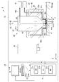
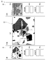
- FIG. 1 is a schematic configuration diagram schematically showing a microscope system of one embodiment, and is a diagram showing a case where an object can be imaged by an optical microscope.
- FIG. 2 is a schematic configuration diagram schematically showing a microscope system of one embodiment, and is a diagram showing a case where an object can be imaged by an electron microscope.
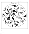
- FIG. 3 is a diagram showing an example of an object observed by the microscope system of one embodiment.
- FIG. 4 is a diagram showing a selection screen of one embodiment.
- FIG. 5 is a diagram showing an observation screen of an optical microscope according to an embodiment.
- FIG. 6 is a screen showing an observation screen of an electron microscope according to an embodiment.
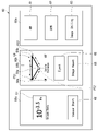
- FIG. 7 is a diagram showing a state in which the observation screen and the navigation screen of the electron microscope of one embodiment are displayed side by side.
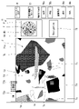
- FIG. 8 is a diagram showing a composite screen of one embodiment.
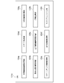
- FIG. 9 is a flowchart showing an example of a procedure performed by the user in the automatic imaging mode of one embodiment.
- FIG. 10 is a flowchart showing an example of the procedure of the calibration step of one embodiment.
- FIG. 11 is a diagram for explaining the XY calibration process of one embodiment.
- FIG. 12 is a diagram for explaining a coordinate axis correction step of one embodiment.
- FIG. 13 is a flowchart showing an example of the procedure of the control method of one embodiment.
- FIG. 14 is a schematic diagram showing a functional unit of a CPU in a modified example of the embodiment.
- the XYZ Cartesian coordinate system is appropriately shown in the drawings, and the positional relationship of each part will be described with reference to this XYZ Cartesian coordinate system.
- the direction parallel to the X axis is described as "first horizontal direction X”
- the direction parallel to the Y axis is described as “second horizontal direction Y”
- the direction parallel to the Z axis is described as “vertical direction Z”. do.
- the first horizontal direction X, the second horizontal direction Y, and the vertical direction Z are directions orthogonal to each other.
- the positive side (+ Z side) of the vertical direction Z facing the Z-axis arrow is described as “upper” or “upper side”, and the negative side of the vertical direction Z opposite to the side facing the Z-axis arrow (+ Z side).
- -Z side is described as "lower side” or “lower side”.
- the vertical direction Z is the height direction.
- the microscope system 1 includes a microscope device 10 and a control unit 20.
- the microscope device 10 is arranged, for example, in atmospheric pressure.
- the microscope device 10 includes an optical microscope (optical device) 30, an electron microscope 40, and a stage 50.
- the optical microscope 30 and the electron microscope 40 are arranged side by side in the first horizontal direction X, for example.
- the electron microscope 40 is arranged, for example, on the right side of the optical microscope 30.
- the type of the optical microscope 30 is not particularly limited.
- the optical microscope 30 may be, for example, a bright-field microscope, a dark-field microscope, a fluorescent microscope, a differential interference microscope, or these microscopes. It may be an appropriate combination of microscopes.
- the optical microscope 30 may have any structure as long as it can acquire the focus information of the object J.
- the optical microscope 30 has a lens 31 facing downward. As shown in FIG. 1, the optical microscope 30 irradiates light L downward from the lens 31 toward the object J on the stage 50 to image the object J.
- the optical axis direction of the light L and the vertical direction Z are substantially parallel.
- the light source that irradiates the light L is not particularly limited.
- the distance Z in the vertical direction from the upper surface 50a of the stage 50 to the lens 31 is expressed as the height H of the lens 31.
- the height H of the lens 31 is the lens (final lens or final optical system) closest to the object J among the plurality of lenses 31 from the upper surface 50a of the stage 50. It is the distance Z in the vertical direction to 31).
- the type of the electron microscope 40 is not particularly limited.
- the electron microscope 40 is, for example, a scanning electron microscope (SEM).
- the electron microscope 40 may be a transmission electron microscope (Transmission Electron Microscope; TEM).
- the electron microscope 40 includes a housing 41, a light source unit 42, a photoelectric unit 43, an electronic lens 44, and an exhaust device 45.
- the housing 41 has, for example, a cylindrical shape extending in the vertical direction Z. Inside the housing 41, an electron beam path 41a through which the electron beam EB passes is provided. The optical axis direction of the electron beam EB and the vertical direction Z are substantially parallel. The electron beam path 41a extends in the vertical direction Z. A photoelectric portion 43 is provided at the upper end of the electron beam path 41a. An injection hole 41c facing downward is provided at the lower end of the housing 41.
- the light source unit 42 is fixed to the upper end surface of the housing 41.
- the light source unit 42 can emit light into the internal space of the housing 41.
- the light emitted from the light source unit 42 into the internal space of the housing 41 is applied to the photoelectric unit 43 provided in the housing 41.
- the photoelectric unit 43 emits an electron beam EB by being irradiated with light due to the photoelectric effect. As shown in FIG. 2, in the present embodiment, the photoelectric unit 43 emits an electron beam EB downward when the light of the light source unit 42 is incident from above. The electron beam EB emitted downward from the photoelectric portion 43 is emitted downward from the emission hole 41c toward the object J through the electron beam path 41a.
- the electronic lens 44 is arranged inside the housing 41.
- the electron lens 44 is arranged below the photoelectric portion 43 so as to surround the electron beam path 41a.
- the electron lens 44 converges the electron beam EB emitted from the photoelectric unit 43 and guides it to the emission hole 41c.
- the electronic lens 44 is a magnetic field lens using a permanent magnet.
- the electronic lens 44 may be a magnetic field lens that does not use a permanent magnet, or may be an electrostatic lens.
- the acceleration voltage applied to the electron beam EB is a voltage applied between the extraction electrode (not shown) arranged below the photoelectric portion 43 in the housing 41 and the photoelectric portion 43.
- the larger the acceleration voltage the lower the focal position of the electron microscope 40. In other words, the larger the acceleration voltage, the deeper the depth of focus of the electron microscope 40.
- the exhaust device 45 includes a nozzle member 46, a first pump 47, and a second pump 48.
- the nozzle member 46 is an annular shape that surrounds the housing 41 around the central axis AX of the electron microscope 40.
- the central axis AX is a virtual line extending in the vertical direction Z. In the present embodiment, the central axis AX passes through the center of the electron beam path 41a.
- the nozzle member 46 has a protruding portion 46a that protrudes downward.
- the protrusion 46a surrounds the lower end surface 41b of the housing 41 around the central axis AX.
- the nozzle member 46 is provided with a first intake flow path 49a.
- a plurality of first intake flow paths 49a are provided, for example.
- the first intake flow path 49a has an intake port 49c that opens to the lower end surface 46b of the protrusion 46a.
- the intake ports 49c in the plurality of first intake flow paths 49a are arranged, for example, on the lower end surface of the protrusion 46a at intervals in the circumferential direction around the central axis AX.
- the first pump 47 and the second pump 48 are vacuum pumps.
- the type of the vacuum pump used as the first pump 47 and the second pump 48 is not particularly limited.
- the first pump 47 is, for example, an oil diffusion pump.
- the second pump 48 is, for example, a pump in which an oil diffusion pump and a turbo molecular pump are combined.
- the first pump 47 is connected to the first intake flow path 49a. Air is sucked into the first intake flow path 49a from the intake port 49c by the first pump 47. As a result, the air between the lower end surface of the protrusion 46a and the stage 50 is sucked into the first intake flow path 49a. At least a part of the air inside the protrusion 46a may be sucked into the first intake flow path 49a.
- the second pump 48 can suck the air in the electron beam path 41a via the second intake flow path 49b.
- the second intake flow path 49b is connected to, for example, the upper end portion in the electron beam path 41a.
- the air in the electron beam path 41a is sucked into the second intake flow path 49b.
- At least a part of the air inside the protrusion 46a may be sucked into the second intake flow path 49b.
- the microscope system 1 can form a local vacuum region G between the object J arranged on the stage 50 and the electron microscope 40.
- the stage 50 is movable below the optical microscope 30 and the electron microscope 40.
- the stage 50 can be moved in each of the first horizontal direction X and the second horizontal direction Y, for example.
- the stage 50 has an upper surface 50a facing upward.
- An object J can be arranged on the upper surface 50a.
- the upper surface 50a is provided with a holding recess 51 that is recessed downward.
- a plate P on which the object J is placed is fitted in the holding recess 51 so that the object J can be held.
- the object J can be arranged on the upper surface 50a of the stage 50 via the plate P.
- the stage 50 may be movable in the vertical direction Z.
- the control unit 20 includes a control device 21, an output unit 22, and an input unit 23.
- the control device 21 is, for example, a PC (personal computer).
- the control device 21 controls the microscope device 10. Specifically, the control device 21 controls the optical microscope 30, the electron microscope 40, and the stage 50. That is, the control unit 20 can control the optical microscope 30, the electron microscope 40, and the stage 50.
- the control device 21 has a CPU (Central Processing Unit) 21a, a ROM (Read Only Memory) 21b, and a RAM (Random access memory) 21c.
- the CPU 21a is a part that performs each control and each process.
- the ROM 21b and the RAM 21c are storage units for storing information (also referred to as storage, storage, etc.).
- the control unit 20 may be a tablet PC in which the control device 21, the output unit 22, and the input unit 23 are integrated.
- storing storing, storing
- it is intended to be stored (saved, stored) in the ROM 21b or RAM 21c.
- the output unit 22 and the input unit 23 are connected to the control device 21 by wire or wirelessly.
- the output unit 22 is, for example, a display device such as a liquid crystal display.
- the output unit 22 is arranged with a display area 100 on which a screen (Graphical User Interface; GUI) for controlling the microscope device 10 is displayed based on the signal output from the control device 21.
- GUI Graphic User Interface
- a screen for controlling the microscope device 10 by activating an information processing program for controlling the microscope device 10 by the CPU 21a is displayed in the display area 100 of the output unit 22.
- the information processing program is installed in the control device 21 in advance, for example. For the sake of simplicity, even when it is intended to "display in the display area 100 of the output unit 22," it may be simply described as "display” or the like.
- the input unit 23 includes, for example, a keyboard 23a and a mouse 23b.
- a signal is input from the input unit 23 to the control device 21.
- the user can control the microscope system 1 via the screen displayed in the display area 100 of the output unit 22, for example, by using the input unit 23.
- the output unit 22 may be provided with a touch panel or the like that functions as an input unit. In that case, when the user operates the output unit 22, a signal is input from the output unit 22 to the control device 21. Specifically, the user can control the microscope system 1 via the screen displayed in the display area 100 of the output unit 22, for example, by using the output unit 22.
- FIG. 3 is a diagram showing an example of an object J observed by the microscope system 1.
- the plurality of objects T include objects T having different sizes, objects T having different shapes, objects T having different colors, and objects T having different materials.
- FIG. 4 is a diagram showing a selection screen 60 displayed in the display area 100 of the output unit 22 of the present embodiment.
- FIG. 5 is a diagram showing an observation screen (OM observation screen) 71 of the optical microscope 30 displayed in the display area 100 of the output unit 22 of the present embodiment.
- FIG. 6 is a screen showing an observation screen 72 of the electron microscope 40 displayed in the display area 100 of the output unit 22 of the present embodiment.
- FIG. 7 is a diagram showing a state in which the observation screen (SEM observation screen) 72 of the electron microscope 40 displayed in the display area 100 of the output unit 22 of the present embodiment and the navigation screen 80 are displayed side by side.
- FIG. 8 is a diagram showing a composite screen 90 displayed in the display area 100 of the output unit 22 of the present embodiment.
- the screens displayed in the display area 100 of the output unit 22 include the selection screen 60, the OM observation screen (first screen) 71, and the SEM observation screen (first screen).
- the selection screen 60 shown in FIG. 4 is, for example, a screen that is first displayed in the display area 100 when the information processing program for controlling the microscope device 10 is started by the control device 21.
- the control device 21 displays the display selection area 60a, the stage control area 60b, and the exhaust control area 60c in the display area 100 as the selection screen 60.
- the display selection area 60a is arranged in the area on the right side of the selection screen 60, for example, on the paper of FIG.
- the stage control area 60b is arranged in the central area of the selection screen 60, for example, on the paper of FIG.
- the exhaust control region 60c is arranged in the left region of the selection screen 60, for example, on the paper of FIG.
- An OM icon (first display icon) 61, an SEM icon (second display icon) 62, and a utility icon 63 are arranged in the display selection area 60a.
- the OM icon 61, the SEM icon 62, and the utility icon 63 are arranged side by side in this order from top to bottom on the selection screen 60, for example, on the paper of FIG.
- the character "OM” is displayed on the OM icon 61.
- the characters "SEM” are displayed on the SEM icon 62.
- the characters "Image Utility" are displayed on the utility icon 63.
- the "icon” in the present specification is an image associated with a file or a program (typically, a computer program that can be executed by the CPU 21a) registered in the control device 21 in advance.
- the user can use each icon to start a desired program.
- the user can control the microscope system 1 by using each icon.
- the control device 21 activates a program associated with the icon.
- the control device 21 causes the microscope system 1 to perform the process associated with the icon.
- the user can display the OM observation screen 71 shown in FIG. 5 by selecting the OM icon 61 by operating the mouse 23b, for example. That is, the OM icon 61 corresponds to the first display icon that displays the OM observation screen 71.
- the user can display the SEM observation screen 72 shown in FIG. 6 by selecting the SEM icon 62 by operating the mouse 23b. That is, the SEM icon 62 corresponds to the second display icon that displays the SEM observation screen 72.
- the user can display the composite screen 90 shown in FIG. 8 by selecting the utility icon 63 by operating the mouse 23b, for example. That is, the utility icon 63 corresponds to an icon that displays the composite screen 90.
- the stage position display 64 is displayed in the stage control area 60b.
- the stage position display 64 is arranged, for example, on the paper surface of FIG. 4 in the upper portion of the stage control area 60b.
- the stage position display 64 displays the position of the stage 50 in the microscope device 10.
- the stage position display 64 has a stage marker 64a and a marker guide 64b.
- the marker guide 64b is, for example, a triangular frame line that is convex downward on the paper surface of FIG. 4.
- the position of the left corner of the corner of the marker guide 64b is the OM observation position PS1.
- the position of the right corner of the corner of the marker guide 64b is the SEM observation position PS2.
- the position of the lower center corner of the corners of the marker guide 64b is the object exchange position PS3.
- the control device 21 moves the stage marker 64a on the marker guide 64b according to the movement of the stage 50.
- the stage marker 64a is displayed, for example, at the object exchange position PS3.
- the control device 21 When the stage 50 is in a position where the object J can be observed by the optical microscope 30 (that is, the position shown in FIG. 1), the control device 21 displays the stage marker 64a at the OM observation position PS1. When the stage 50 is in a position where the object J can be observed by the electron microscope 40 (that is, the position shown in FIG. 2), the control device 21 displays the stage marker 64a at the SEM observation position PS2. When the stage 50 is in a position where the object J on the stage 50 can be exchanged by the user, the control device 21 displays the stage marker 64a at the object exchange position PS3.
- the position where the stage 50 can exchange the object J on the stage 50 by the user is, for example, a position not located below the optical microscope 30 or below the electron microscope 40.
- the control unit 20 outputs the stage position display 64 to the output unit 22 as information indicating the relative position between the stage 50 and the optical microscope 30 or the relative position between the stage 50 and the electron microscope 40. It can be displayed.
- the user can exchange the object J on the stage 50 means that the user can exchange the object J on the stage 50 directly or indirectly by using another transport device or the like. All you need is.
- the take-out icon 65 and the reset icon 66 are arranged in the stage control area 60b.
- the take-out icon 65 and the reset icon 66 are arranged below the stage position display 64.
- the characters "Eject” are displayed on the eject icon 65.
- the characters "Stage Reset” are displayed on the reset icon 66.
- the take-out icon 65 is an icon that moves the stage 50 to a position where the user can exchange the object J.
- the user can move the stage 50 to a position where the object J can be exchanged by selecting the take-out icon 65 by operating the mouse 23b. That is, when the control device 21 detects that the take-out icon 65 is selected by the mouse 23b, the control device 21 controls a movement mechanism (not shown) to move the stage 50 to a position where the user can exchange the object J.
- the reset icon 66 is arranged below the take-out icon 65, for example, on the paper of FIG.
- the reset icon 66 is an icon that returns the position of the stage 50 to the initial position.
- the initial position includes an initial position at a position where the object J can be observed by the optical microscope 30 and an initial position at a position where the object J can be observed by the electron microscope 40.
- the user can set the stage 50 at the initial position among the positions where the object J can be observed by the optical microscope 30, or the object J by the electron microscope 40. It can be moved to the initial position among the observable positions.
- the stage 50 is the initial position in which the object J can be observed by the optical microscope 30. Move to position.
- the stage 50 is the initial position in which the object J can be observed by the electron microscope 40. Move to position.
- the atmospheric pressure display 67 is displayed in the exhaust control area 60c.
- the atmospheric pressure display 67 is displayed on the upper portion in the exhaust control region 60c.
- the atmospheric pressure display 67 displays the atmospheric pressure in the electron microscope 40.
- the characters "Vacuum State” are labeled below the atmospheric pressure display 67.
- the air pressure in the electron microscope 40 includes the air pressure in the electron beam path 41a, the air pressure in the protrusion 46a, and the air pressure between the electron microscope 40 and the stage 50.
- the air pressure in the electron microscope 40 includes the air pressure in the local vacuum region G between the object J arranged on the stage 50 and the electron microscope 40.
- the intake start icon 68 is arranged in the exhaust control area 60c. In the paper of FIG. 4, the intake start icon 68 is arranged below the barometric pressure display 67. For example, the characters "Vacuum Start” are displayed on the intake start icon 68.
- the intake start icon 68 is an icon for starting intake by the exhaust device 45 of the electron microscope 40. For example, the user can start the intake by the exhaust device 45 by selecting the intake start icon 68 by operating the mouse 23b, and create a local vacuum region G between the stage 50 and the electron microscope 40. Can be done.
- the OM observation screen 71 shown in FIG. 5 corresponds to the first screen in which the object J is imaged and displayed by the optical microscope 30.
- the SEM observation screen 72 shown in FIG. 6 corresponds to a second screen in which the object J is imaged and displayed by the electron microscope 40.
- the stage 50 is arranged at a position where the object J can be imaged by the optical microscope 30.
- the stage 50 is arranged at a position where the object J can be imaged by the electron microscope 40.
- the control device 21 displays switching icons 73a and 73b for switching to the other screen on the OM observation screen 71 and the SEM observation screen 72, respectively.
- the switching icon 73a is an icon for switching the SEM observation screen 72 to the OM observation screen 71.
- the switching icon 73b is an icon for switching the OM observation screen 71 to the SEM observation screen 72.
- the switching icon 73a and the switching icon 73b are displayed on both the OM observation screen 71 and the SEM observation screen 72.
- the switching icon 73a and the switching icon 73b are arranged side by side in the left-right direction on the upper left of the first display units 71a and 72a, which will be described later.
- the character "OM” is displayed on the switching icon 73a.
- the characters "SEM" are displayed on the switching icon 73b.
- the switching icon 73a is displayed brightly and the switching icon 73b is displayed dark on the OM observation screen 71.
- “Bright” means a state in which the amount of light in the display area 100 is large and the user can clearly see it visually.
- the “dark” means a state in which the amount of light in the display area 100 is small and the user cannot visually clearly see it.
- the characters "OM" displayed on the switching icon 73a are highlighted. On the OM observation screen 71, the switching icon 73a does not work.
- the user can switch the screen from the OM observation screen 71 to the SEM observation screen 72 by selecting, for example, the switching icon 73b displayed on the OM observation screen 71 by operating the mouse 23b.
- the control device 21 moves the stage 50 from a position where the object J can be imaged by the optical microscope 30 to a position where the object J can be imaged by the electron microscope 40. Let me.
- the switching icon 73b is displayed brightly, and the switching icon 73a is displayed darkly.
- the characters "SEM" displayed on the switching icon 73b are highlighted, and the screen currently displayed is the SEM observation screen 72 of the OM observation screen 71 and the SEM observation screen 72. Shown.
- the switching icon 73b does not work.
- the user can switch the screen from the SEM observation screen 72 to the OM observation screen 71 by selecting, for example, the switching icon 73a displayed on the SEM observation screen 72 by operating the mouse 23b.
- the control device 21 moves the stage 50 from a position where the object J can be imaged by the electron microscope 40 to a position where the object J can be imaged by the optical microscope 30. Let me.
- the control device 21 displays the first display unit 71a as a part of the OM observation screen 71.
- the control device 21 displays the first display unit 72a as a part of the SEM observation screen 72.
- the first display units 71a and 72a are display units that display real-time images of the object J, respectively.
- the real-time image is not an image captured in the past, but an image captured in the present progressive tense.
- the first display unit 71a displays a real-time image of the object J captured by the optical microscope 30.
- the first display unit 72a displays a real-time image of the object J captured by the electron microscope 40.
- the control unit 20 can display the image captured by the optical microscope 30 and the image captured by the electron microscope 40 on the output unit 22.
- Each of the first display units 71a and 72a is the portion displayed in the largest size on each observation screen.
- the OM observation screen 71 and the SEM observation screen 72 are different from each other in that the display unit for displaying the object J is different between the first display unit 71a and the first display unit 72a, and the above-mentioned switching icons 73a and 73b. It is a similar screen except that the display of is different.
- the first display unit 71a is switched to the first display unit 72a.
- the first display unit 72a is switched to the first display unit 71a.
- control unit 20 can switch between the display of the image captured by the optical microscope 30 and the display of the image captured by the electron microscope 40 by switching the screen based on the operation by the user.
- control unit 20 can switch between displaying a real-time image captured by the optical microscope 30 and displaying a real-time image captured by the electron microscope 40.
- the center position of the image (real-time image) displayed on the first display units 71a and 72a, which is switched when the switching icons 73a and 73b are selected reflects the same location on the same object J.
- the image magnification of the optical microscope 30 and the image magnification of the electron microscope 40 are the same as in the examples of FIGS. 5 and 6, the first display unit 71a, which is switched when the switching icons 73a and 73b are selected.
- the image (real-time image) reflected on 72a is, for example, an image (real-time image) of the same range in the same object J.
- the imaging magnification of the optical microscope 30 and the imaging magnification of the electron microscope 40 are the same, when the screen is switched from the OM observation screen 71 to the SEM observation screen 72, the first display unit 71a on the OM observation screen 71 An image (real-time image) captured by the electron microscope 40 in the same range as the range of the object J displayed on the SEM observation screen 72 is displayed on the first display unit 72a of the SEM observation screen 72.
- an image captured by the optical microscope 30 in the same range as the range of the object J displayed on the first display unit 72a on the SEM observation screen 72 when the screen is switched from the SEM observation screen 72 to the OM observation screen 71, an image captured by the optical microscope 30 in the same range as the range of the object J displayed on the first display unit 72a on the SEM observation screen 72.
- (Real-time image) is displayed on the first display unit 71a of the OM observation screen 71.
- the real-time image captured by the optical microscope 30 switched to each other and the real-time image captured by the electron microscope 40 include images in the same range in the same object J.
- the imaging magnification of the electron microscope 40 is larger than the imaging magnification of the optical microscope 30
- the screen is switched from the OM observation screen 71 to the SEM observation screen 72
- the OM observation screen 71 is displayed on the first display unit 72a.
- An enlarged image of the central portion of the image displayed on the first display unit 71a of the above is displayed.
- the real-time image captured by the optical microscope 30 is switched to the real-time image captured by the electronic microscope 40, the real-time image after the switching is the optical microscope 30 before the switching. It is included that it is an enlarged image of a part of the range of the object J projected on the image captured by.
- the image of the object J displayed on the first display unit 71a of the OM observation screen 71 contains information on the color of the object J.
- the image of the object J reflected on the first display unit 71a is a color image.
- the objects Ta to Te having different colors are displayed on the first display unit 71a.
- the image of the object J displayed on the first display unit 72a of the SEM observation screen 72 is information about the material of the object J and the height direction (vertical direction Z) of the object J. Contains information about the uneven shape of.
- the image of the object J reflected on the first display unit 72a is a monochrome image.
- the black object T1 and the white object T2 are displayed on the first display unit 72a.
- an element having a relatively small mass such as carbon tends to appear black
- an element having a relatively large mass such as metal tends to appear white.
- the black-and-white color information indicates the information of the material of the object J.
- the black object T1 is a non-metal such as carbon
- the white object T2 is a metal.
- the image of the object J displayed on the first display unit 71a of the OM observation screen 71 is, for example, the optics of the object J captured by the optical microscope 30 in a state where the focus is adjusted by the autofocus function of the optical microscope 30. It is a microscope image.
- This light microscope image may be an image in which a part of the displayed area is in focus (focused), or an image in which all of the displayed area is in focus (). It may be an omnidirectional image). Examples of the omnifocal image include a depth composite image IM1a described later.
- the image of the object J displayed on the first display unit 72a of the SEM observation screen 72 is, for example, an electron microscope 40 in a state where the focus is adjusted based on the information of the object J obtained from the optical microscope 30. It is an electron microscope image of the object J imaged by.
- This electron microscope image is an image that is in focus (focused). That is, the image captured by the electron microscope 40 in the present embodiment includes an image captured by adjusting the focus of the electron microscope 40 based on the information obtained from the optical microscope 30.
- the focus adjusting method of the present embodiment includes adjusting the focus of the electron microscope 40 based on the information of the object J obtained from the optical microscope 30.
- the information of the object J obtained from the optical microscope 30 includes the focus information (focus information) of the object J to be imaged.
- the focus information of the object J is information on the position of the object J in the vertical direction Z from a certain reference position, and is necessary for focusing on a portion of the object J located at a certain height. Includes information and more.
- the focal information required to focus on a portion of the object J located at a certain height includes the height H of the lens 31 of the optical microscope 30 with respect to the upper surface 50a of the stage 50.
- the control unit 20 acquires, for example, the height H of the lens 31 capable of focusing on a predetermined object J with an optical microscope 30 as information related to the height of the object J.
- the control unit 20 acquires in advance the relationship between the height H of the lens 31 and the acceleration voltage applied to the electron beam EB by the Z calibration step Sc2 described later.
- the control unit 20 can focus the electron microscope 40 on the portion of the object J that the optical microscope 30 focuses on when the height H of the lens 31 is a certain value. The value of can be calculated. Therefore, when the optical microscope 30 and the electron microscope 40 image the same part of the same object J, the lens 31 required to first image the part with the optical microscope 30 and focus the optical microscope 30.
- the acceleration voltage can be calculated from the height H and the electron microscope 40 can be focused on the portion. That is, it is not necessary to adjust the focus while imaging the object J with the electron microscope 40 as in the conventional case, and by applying the calculated acceleration voltage and emitting the electron beam EB, the image is captured by the electron microscope 40. You can capture a focused image from the moment you start.
- the relationship between the height H of the lens 31 and the acceleration voltage applied to the electron beam EB is, for example, linear.
- the relationship between the height H of the lens 31 and the acceleration voltage applied to the electron beam EB is stored in, for example, ROM 21b or RAM 21c. Then, when the focus is controlled by the electron microscope 40 or the optical microscope 30, the relationship between the height H of the lens 31 and the acceleration voltage applied to the electron beam EB is used.
- control unit 20 is related to the height of the object J based on the relationship between the acceleration voltage in the electron microscope 40 and the information related to the height of the object J obtained from the optical microscope 30.
- the focus of the electron microscope 40 can be adjusted by calculating the value of the acceleration voltage of the electron microscope 40 from the information and adjusting the acceleration voltage of the electron microscope 40 to the calculated value.
- the focus of the electron microscope 40 can be adjusted based on the image pickup result of the optical microscope 30. Therefore, if the object J is first imaged by the optical microscope 30, when the SEM observation screen 72 is displayed, the electron microscope image focused from the beginning can be displayed on the first display unit 72a. As described above, in the present embodiment, when the real-time image captured by the optical microscope 30 is switched to the real-time image captured by the electron microscope 40, the real-time image after the switching is displayed from the time when the display is started. The image includes that the focus of the electron microscope 40 is adjusted to obtain an image.
- the control unit 20 takes an image of the entire object J with an optical microscope 30 and obtains the focus information of the imaged object J. You may get it. In this case, even if the SEM observation screen 72 is displayed before the OM observation screen 71, the information acquired in advance by the optical microscope 30 is used to initially display the SEM observation screen 72 on the first display unit 72a. It is possible to display a real-time image captured by the electron microscope 40 in a focused state.
- the user selects and selects a part of the optical microscope image displayed on the first display unit 71a of the OM observation screen 71 by operating the mouse 23b, so that the image is displayed on the first display unit 71a.
- the optical microscope image to be obtained can be switched to an image in which the object J is imaged centering on the portion of the object J corresponding to a part of the selected optical microscope image.
- the user selects and selects a part of the electron microscope image displayed on the first display unit 72a of the SEM observation screen 72 by operating the mouse 23b, so that the image is displayed on the first display unit 72a.
- the electron microscope image to be obtained can be switched to an image in which the object J is imaged centering on the portion of the object J corresponding to a part of the selected electron microscope image.
- the control device 21 displays the second display unit 74 as a part of the OM observation screen 71 and the SEM observation screen 72.
- the second display unit 74 is a display unit that displays the entire image of the object J.
- the second display unit 74 is displayed on the right side of the first display units 71a and 72a on the OM observation screen 71 and the SEM observation screen 72, respectively.
- the second display unit 74 is smaller than the first display units 71a and 72a.
- the second display unit 74 displays an image showing the entire object J and the entire plate P on which the object J is placed.
- the image displayed on the second display unit 74 is not a real-time image, but an image captured before each observation screen is displayed.
- the image displayed on the second display unit 74 may be an image captured by the optical microscope 30, an image captured by the electron microscope 40, or an image IM1 described later. Alternatively, it may be the image IM2 described later.
- a mark M1 indicating the position of the range of the object J reflected in the real-time image displayed on the first display units 71a and 72a is displayed.
- the mark M1 is a cross-shaped mark.
- the portion of the object J corresponding to a predetermined range centered on the position where the centers of the cross-shaped marks M1 overlap is displayed on the first display units 71a and 72a in real time. Is displayed.
- the range of the object J displayed on the first display units 71a and 72a changes depending on the imaging magnification of each microscope. 5 and 6 show a case where, for example, the imaging magnification of the optical microscope 30 and the imaging magnification of the electron microscope 40 are the same, and the same range of the object J is imaged.
- the user selects a part of the entire image of the object J displayed on the second display unit 74, so that the real-time image displayed on the first display units 71a and 72a is displayed in the second display. It is possible to switch to a real-time image that captures the range of the object J corresponding to a part of the image selected on the unit 74.
- the portion of the object J corresponding to the selected portion is the first display unit.
- the stage 50 moves so as to be reflected at the center position of the images displayed on 71a and 72a.
- the portion of the object J corresponding to the portion selected on the image displayed on the second display unit 74 can be projected on the first display units 71a and 72a.
- the mark M1 moves to a position selected by the user on the image displayed on the second display unit 74.
- the image displayed on the second display unit 74 includes the focus information of the object J described above, or when the focus information of the object J is associated with the image, the image is displayed on the second display unit 74.
- the real-time image displayed on the first display unit 72a of the SEM observation screen 72 can be made into a focused image from the beginning.
- the case where the image displayed on the second display unit 74 includes the focus information of the object J described above and the case where the focus information of the object J is associated are displayed on the second display unit 74, for example. This includes the case where the image is the depth composite image IM1a described later.
- the control device 21 displays the navigation icon 75 as a part of the OM observation screen 71 and the SEM observation screen 72.
- the characters "Navigation" are displayed on the navigation icon 75.
- the navigation icon 75 is an icon for displaying the navigation screen 80 shown in FIG. 7.
- the navigation icon 75 is arranged below the second display unit 74 on each observation screen.
- the user can display the navigation screen (first acquisition screen) 80 shown in FIG. 7, for example, by selecting the navigation icon 75 by operating the mouse 23b.
- the navigation screen 80 can be displayed at the same time as the observation screen of either the OM observation screen 71 or the SEM observation screen 72.
- FIG. 7 shows a case where the navigation screen 80 is displayed at the same time as the SEM observation screen 72.
- the characters "Navigation" are displayed on the upper left of the navigation screen 80.
- the navigation screen 80 is a first acquisition screen for acquiring an image IM1 obtained based on a plurality of images captured by the optical microscope 30. In this way, the control unit 20 can display the navigation screen 80 on the output unit 22 as the first acquisition screen for acquiring the image IM1.
- the image IM1 includes a depth composite image (first image, second image, composite image) IM1a and a stitching image IM1b.
- the expression “acquire an image” is synonymous with “generate an image”, “create an image”, and the like.
- Depth composite image IM1a is an image created by depth compositing a plurality of images.
- the depth composite image IM1a is a plurality of optical microscope images acquired by imaging the object J a plurality of times with different positional relationships between the focal position and the object in the vertical direction Z by the optical microscope 30. Is made by depth synthesis.
- the depth composite image IM1a is a focused pixel information (focused pixel information) in a plurality of optical microscope images acquired by imaging the object J multiple times with different positional relationships between the focal position and the object in the vertical direction Z. It is a composite image composed of (simply also referred to as pixels).
- the depth composite image IM1a is an image formed by focused pixels obtained from a plurality of images having different positional relationships between the focal position and the object in the vertical direction Z. Further, the depth composite image IM1a is a omnifocal image in which the entire range of the object J reflected in the image is in focus.
- each of the plurality of pixels constituting the depth composite image IM1a includes the focus information for the object J.
- the pixel includes color information (color tone and gradation) when the control device 21 handles an image.
- the plurality of pixels constituting the depth composite image IM1a include focus information at the portion of the object J corresponding to the position of each pixel.
- this focal information is information indicating the positional relationship between the focal position and the object in the vertical direction.
- the focus information is information indicating that "it is the Xth image in the Z direction”.
- the focal information is information indicating "the value of the height H of the lens 31".
- the value of the height H of the lens 31 is information indicating at which focal position the optical microscope image was captured. Therefore, appropriate focus information can be acquired from each of the plurality of pixels of the depth composite image IM1a.
- the plurality of pixels constituting the depth composite image IM1a may not directly include the focal information but may be associated with the focal information included in the focal table stored in the ROM 21b or the RAM 21c. Even in this case, the value of the height H of the lens 31 associated with the plurality of pixels of the depth composite image IM1a can be acquired from the ROM 21b or the RAM 21c.
- the focus table is data in which the pixel positions of the depth composite image and the focus information are associated with each other.
- the stitching image IM1b is an image created by joining a plurality of images at different positions on the XY plane (horizontal plane).
- the stitching image IM1b is an image created by joining nine optical microscope images of three rows and three columns captured by an optical microscope 30.
- the nine optical microscope images constituting the stitching image IM1b in the present embodiment are the depth composite image IM1a.
- the control device 21 displays the third display unit 85 on which the image IM1 is displayed as a part of the navigation screen 80.
- the stitching image IM1b is displayed on the third display unit 85.
- the navigation screen 80 for example, the image is not displayed on the third display unit 85.
- the acquired image IM1 is displayed on the third display unit 85.
- a mode selection field 81 On the navigation screen 80, a mode selection field 81, an image pickup range designation field 82, and an image pickup start icon 83 are arranged.
- the mode selection field 81, the image pickup range designation field 82, and the image pickup start icon 83 are arranged side by side in this order from the upper side to the lower side on the right side of the third display unit 85.
- the characters "mode” are displayed on the upper side of the mode selection field 81.
- the characters "imaging range designation" are displayed on the upper side of the imaging range designation field 82.
- the character "imaging" is displayed on the imaging start icon 83.
- the mode selection field 81 is a field for selecting a mode for acquiring the image IM1.
- the mode selection field 81 is, for example, a drop-down list in which a value (character or the like) indicating a selectable mode is input.
- the user can select one mode in the mode selection field 81, for example, by operating the mouse 23b.
- the modes that can be selected in the mode selection field 81 include a depth synthesis mode and a non-depth synthesis mode.
- the depth composition mode is a mode for acquiring an image IM1 using depth composition.
- the non-depth composition mode is a mode for acquiring an image IM1 without using depth composition.
- the character "Focus Stacking" displayed in the mode selection field 81 indicates that the depth stacking mode is selected as the mode for acquiring the image IM1.
- the image pickup range designation column 82 is a column for designating the image pickup range required for acquiring the image IM1.
- the image pickup range designation field 82 is, for example, a drop-down list in which a value (character or the like) indicating a selectable image pickup range is input.
- the user can specify one imaging range in the imaging range designation field 82, for example, by operating the mouse 23b.
- the imaging range that can be specified in the imaging range designation field 82 is the range of the object J that can be imaged by one imaging by the optical microscope 30, and the range of the object J that can be imaged by imaging at a plurality of different points. ,including.
- the character "3 ⁇ 3" displayed in the imaging range designation column 82 is an object that can be imaged as a whole by imaging at 9 locations arranged in 3 rows and 3 columns as an imaging range. Indicates that the range of the object J is specified. At this time, the center position of the object J in the center portion CF of the nine locations corresponds to the center position of the image displayed on the first display unit 72a on the SEM observation screen 72 displayed at the same time as the navigation screen 80. Is.
- the imaging range that can be specified in the imaging range designation field 82 is an object corresponding to the image displayed on the first display units 71a and 72a of the OM observation screen 71 or the SEM observation screen 72 displayed at the same time as the navigation screen 80. Includes a predetermined range centered on the position of the object J.
- the control unit 20 can specify the range of the object J for acquiring the image IM1 on the navigation screen 80 as the first acquisition screen.
- FIG. 7 shows a state in which the portion of the object J displayed on the first display unit 72a of the SEM observation screen 72 is changed after the image IM1 is acquired. Therefore, in FIG. 7, the center position of the object J with respect to the center position of the image IM1 displayed on the third display unit 85 of the navigation screen 80 is the electron microscope image displayed on the first display unit 72a of the SEM observation screen 72. It is different from the center position of the object J with respect to the center position of.
- the image pickup start icon 83 is an icon for starting the acquisition of the image IM1. For example, by selecting the image pickup start icon 83 by operating the mouse 23b, the user can acquire the image IM1 based on the mode selected in the mode selection field 81 and the image pickup range selected in the image pickup range designation field 82. can.
- the control unit 20 uses the optical microscope 30 to make a plurality of optical microscopes having different focal positions at each of the nine locations of the designated vertical and horizontal 3 rows and 3 columns. Get an image.
- the control unit 20 acquires the focal information (for example, the height H of the lens 31) for each part of the object J by the optical microscope 30.
- the control unit 20 depth-synthesizes the acquired plurality of optical microscope images, and acquires a plurality of depth-combined images IM1a corresponding to each of the captured portions.
- the control unit 20 acquires the stitching image IM1b by connecting a plurality of the acquired depth composite images IM1a and displays them on the third display unit 85. In this way, in the present embodiment, the control unit 20 can display the image IM1 obtained based on the plurality of images captured by the optical microscope 30.
- the user By selecting a part of the image IM1 displayed on the third display unit 85 of the navigation screen 80, the user selects the first display unit 71a on the OM observation screen 71 or the SEM observation screen 72 displayed at the same time as the navigation screen 80. , 72a can be changed to an image that captures the portion of the object J corresponding to the portion selected in the image IM1.
- the user can select a part of the image IM1 by, for example, selecting a part of the image IM1 displayed on the third display unit 85 by operating the mouse 23b.
- a real-time image in which a predetermined range centered on the part of the object J corresponding to the selected part of the image IM1 is captured is displayed at the same time as the navigation screen 80. It is displayed on the first display units 71a and 72a of the observation screen.
- the image IM1 displayed on the third display unit 85 of the navigation screen 80 is an optical microscope image captured by the optical microscope 30.
- the image displayed on the first display unit 72a of the SEM observation screen 72 is an electron microscope image captured by the electron microscope 40.
- the control unit 20 can simultaneously display the image captured by the optical microscope 30 and the image captured by the electron microscope 40.
- the image IM1 displayed on the third display unit 85 of the navigation screen 80 is the stitching image IM1b as in the present embodiment, it is displayed on the first display unit 72a of the SEM observation screen 72 displayed at the same time as the navigation screen 80.
- the image to be displayed is an image obtained by enlarging a part of the range of the object J displayed in the image displayed on the third display unit 85. That is, in the present embodiment, in the image captured by the optical microscope 30 and the image captured by the electron microscope 40 displayed at the same time, the image captured by the electron microscope 40 becomes the image captured by the optical microscope 30. Includes an image taken by enlarging a part of the range of the object J to be reflected.
- the image displayed on the first display unit 72a of the SEM observation screen 72 displayed at the same time as the navigation screen 80 captures the same range as the range of the object J displayed on the image displayed on the third display unit 85. It may be an image that has been created.
- the images captured by the optical microscope 30 and the images captured by the electron microscope 40 simultaneously displayed include images captured in the same range of the same object J.
- the image displayed by selecting a part of the image IM1 displayed on the third display unit 85 is the first display unit 72a of the SEM observation screen 72. It is an electron microscope image displayed in. That is, in the present embodiment, when a part of the image IM1 is selected, the control unit 20 captures the range of the object J corresponding to the part of the selected image IM1 with the electron microscope 40 and outputs the output unit 22. It can be displayed in. Further, in the present embodiment, when a part of the image IM1 is selected, the control unit 20 captures the range of the object J corresponding to the part of the selected image IM1 with the electron microscope 40, and together with the image IM1. It can be displayed at the same time.
- the focus of the image displayed on the first display unit 72a of the SEM observation screen 72 is adjusted based on the focus information as described above. It becomes a real-time image taken by the electron microscope 40. That is, in the present embodiment, the control unit 20 focuses the electron microscope 40 on the designated portion based on the focus information of the object J in the designated portion among the portions of the object J. Therefore, when a part of the image IM1 is selected by the user, the real-time image displayed on the first display unit 72a of the SEM observation screen 72 is a real-time image in a focused state from the beginning. That is, in the present embodiment, the image captured by the electron microscope 40 displayed when a part of the image IM1 is selected is a real-time image, and the focus of the electron microscope 40 is from the time when the display is started. The image is adjusted and captured.
- the image IM1 displayed on the third display unit 85 in the present embodiment is the depth composite image IM1a
- the part of the object J corresponding to the selected part is displayed.
- the acceleration voltage for focusing the electron microscope 40 can be calculated based on the focus information. Therefore, no matter which part of the image IM1 is selected by the user, the electron microscope image in a state in which the first display unit 72a of the SEM observation screen 72 is in focus can be displayed.
- control unit 20 obtains the focus adjustment of the electron microscope 40 from the image IM1 when a part of the image IM1 is selected and the image captured by the electron microscope 40 is displayed. It can be automatically performed based on the focus information of the object J to be.
- the optical microscope image (image IM1) of the object J in focus is displayed, and a predetermined position of the optical microscope image (image IM1) is designated. And, based on the focal information contained in the optical microscope image (image IM1), displaying an electron microscope image of the object J in which the position corresponding to the predetermined position is focused. Further, the image display method of the present embodiment displays an optical microscope image (image IM1) in which the object is in focus, and an optical microscope image with respect to a position specified in the optical microscope image (image IM1).
- Image IM1 includes displaying an electron microscope image of an object J in focus based on the focus information contained in (Image IM1).
- the mark M2 is displayed in the selected part on the image IM1.
- the mark M2 is a cross-shaped mark.
- the portion of the object J corresponding to a predetermined range centered on the position where the centers of the cross-shaped marks M2 overlap in the image IM1 displayed on the third display unit 85 is displayed on the first display units 71a and 72a in real time. ..
- the first display unit 72a of the SEM observation screen 72 shown in FIG. 7 displays an image captured by the electron microscope 40 at a higher imaging magnification than that shown in FIG.
- the image IM1 is the target currently being imaged by the electron microscope 40.
- a mark M2 indicating the position of the range of the object J is displayed.
- the image captured by the optical microscope 30 is referred to by the electron microscope 40.
- a mark M2 indicating the position of the range of the object J reflected in the captured image is displayed.
- the control device 21 displays the autofocus function switching icon 84 as a part of the navigation screen 80.
- the autofocus function switching icon 84 is arranged on the upper side of the third display unit 85.
- the autofocus function switching icon 84 is used when the portion of the object J corresponding to the selected portion on the image IM1 displayed on the navigation screen 80 is imaged and displayed on the OM observation screen 71 or the SEM observation screen 72. It is an icon that can switch whether or not to perform focus adjustment at the time of imaging based on the information contained in the image IM1.
- the autofocus function switching icon 84 includes an ON icon 84a and an OFF icon 84b. For example, the character "ON" is displayed on the ON icon 84a.
- the character "OFF” is displayed on the OFF icon 84b.
- the characters "Auto Focus” are displayed above the ON icon 84a and the OFF icon 84b.
- the user can turn on the autofocus function based on the information contained in the image IM1 by selecting the ON icon 84a by operating the mouse 23b.
- the user can turn off the autofocus function based on the information included in the image IM1 by selecting the OFF icon 84b by operating the mouse 23b, for example.
- the focus information contained in the selected part of the image IM1 is used as the focus information.
- the focus of the electron microscope 40 is automatically adjusted. As a result, the portion of the object J corresponding to the selected portion in the image IM1 can be imaged by the electron microscope 40 whose focus is automatically adjusted.
- the electron microscope 40 based on the information contained in the image IM1 even if the user selects a part of the image IM1.
- the focus is not adjusted.
- the focus of the electron microscope 40 may be adjusted based on separately set conditions or the like, or may be manually adjusted by the user.
- control unit 20 of the present embodiment obtains the focus adjustment of the electron microscope 40 from the image IM1 when a part of the image IM1 is selected and the image captured by the electron microscope 40 is displayed. It is possible to switch whether or not to perform the automatic operation based on the focus information of the object J.
- the control device 21 displays the three-dimensional image acquisition icon 86 as a part of the navigation screen 80.
- the three-dimensional image acquisition icon 86 is arranged on the right side of the third display unit 85 and below the image pickup start icon 83.
- the characters "three-dimensional image” are displayed on the three-dimensional image acquisition icon 86.
- the three-dimensional image acquisition icon 86 is an icon that can acquire a three-dimensional image based on the pixel information included in the depth composite image IM1a. After acquiring the depth composite image IM1a described above, the user selects the three-dimensional image acquisition icon 86 by operating the mouse 23b to acquire a three-dimensional image showing the three-dimensional shape of the object J.
- the three-dimensional image is displayed, for example, on a separately displayed display screen.
- the three-dimensional image may be created based on the image captured by the optical microscope 30, may be created based on the image captured by the electron microscope 40, or may be created based on the image captured by the optical microscope 30 and the image captured by the optical microscope 30. It may be made based on the image taken by the electron microscope 40.
- the user can view the three-dimensional image from any viewpoint.
- the control device 21 displays the focus setting icon 76 as a part of the OM observation screen 71 and the SEM observation screen 72.
- the character "focus setting” is displayed on the focus setting icon 76.
- the focus setting icon 76 is an icon for displaying a focus setting screen (not shown).
- the user can display the focus setting screen by selecting the focus setting icon 76 by operating the mouse 23b, for example.
- settings related to focus adjustment of the optical microscope 30 and settings related to focus adjustment of the electron microscope 40 can be made.
- the user can manually adjust the focus of the optical microscope 30 and the focus of the electron microscope 40 on the focus setting screen.
- the control unit 20 can automatically adjust the focus of the electron microscope 40 based on the focus information of the object J obtained from the image IM1, and then manually further adjust the focus. And.
- the focus adjustment method of the present embodiment uses both the focus adjustment method based on the information of the object J obtained from the optical microscope 30 and the manual focus adjustment method of the electron microscope 40. Includes adjusting focus. Further, the focus adjustment method of the present embodiment includes adjusting the focus of the electron microscope 40 based on the information of the object J obtained from the optical microscope 30, and then manually adjusting the focus of the electron microscope 40. ..
- the user can set whether or not to use the autofocus function of the electron microscope 40 when adjusting the focus of the electron microscope 40 on the focus setting screen.
- the autofocus function of the electron microscope 40 is used.
- the focus of the electron microscope 40 is further adjusted. That is, in the present embodiment, the control unit 20 automatically adjusts the focus of the electron microscope 40 based on the focus information of the object J obtained from the image IM1, and then uses the autofocus function of the electron microscope 40. Further can be done.
- the focus adjustment method of the present embodiment uses both the focus adjustment method based on the information of the object J obtained from the optical microscope 30 and the focus adjustment method by the autofocus function of the electron microscope 40. Including adjusting the focus of the electron microscope 40. Further, in the focus adjustment method of the present embodiment, after adjusting the focus of the electron microscope 40 based on the information of the object J obtained from the optical microscope 30, the autofocus function of the electron microscope 40 is used to adjust the focus of the electron microscope 40. Includes further adjustment of focus.
- the autofocus function of the electron microscope 40 is not used when adjusting the focus of the electron microscope 40.
- control unit 20 of the present embodiment automatically adjusts the focus of the electron microscope 40 based on the focus information of the object J obtained from the image IM1 and then uses the autofocus function of the electron microscope 40. It is possible to switch whether or not to further adjust the focus of the electron microscope 40.
- the same settings as those that can be switched by the autofocus function switching icon 84 arranged on the navigation screen 80 can be made. That is, on the focus setting screen, the user can set whether or not to adjust the focus of the electron microscope 40 using the focus information of the object J obtained by the optical microscope 30.
- the focus adjustment of the electron microscope 40 is set. For example, the focus adjustment using the auto-focus function of the electron microscope 40 and the manual focus adjustment by the user are performed using at least one of them.
- the control device 21 displays the automatic imaging mode icon 77 as a part of the OM observation screen 71 and the SEM observation screen 72.
- the characters "automatic imaging mode" are displayed on the automatic imaging mode icon 77.
- the automatic image pickup mode icon 77 is an icon that sets the image pickup mode of the electron microscope 40 to the automatic image pickup mode.
- the automatic image pickup mode is a mode in which the electron microscope 40 automatically captures a plurality of points of the object J corresponding to the plurality of points designated in the image IM1.
- a plurality of locations of the object J corresponding to the plurality of locations designated in the depth composite image IM1a are automatically imaged by the electron microscope 40.
- magnification can also be specified.
- the user can set the imaging mode of the electron microscope 40 to the automatic imaging mode by selecting the automatic imaging mode icon 77 by operating the mouse 23b.
- FIG. 9 is a flowchart showing an example of a procedure performed by the user in the automatic imaging mode.
- the user selects the automatic image pickup mode icon 77 with the mouse 23b and selects the automatic image pickup mode (step S11).
- the automatic imaging mode setting screen is displayed. The user can set necessary conditions and the like on the automatic image pickup mode setting screen. In addition, instructions to the user and the like are displayed on the automatic image pickup mode setting screen.
- the control unit 20 acquires the depth composite image IM1a (image IM1) to the user by displaying a message on the output unit 22 or the like. To instruct. At this time, if the navigation screen 80 is not displayed, the control unit 20 displays the navigation screen 80 together with a message or the like. The user acquires the depth composite image IM1a on the navigation screen 80 as described above (step S12). If the depth composite image IM1a has not been acquired, the control unit 20 may automatically acquire the depth composite image IM1a (image IM1).
- the control unit 20 instructs the output unit 22 to specify an image pickup location in the depth composite image IM1a by displaying a message or the like.
- the control unit 20 tells the user the depth composite image. It is instructed to specify the imaging location on the depth composite image IM1a without instructing the acquisition of IM1a.
- the user selects a desired plurality of locations on the depth composite image IM1a displayed on the third display unit 85 of the navigation screen 80, for example, by selecting them with the mouse 23b.
- the user designates the imaging location in the depth composite image IM1a (step S13). That is, in the control unit 20 of the present embodiment, the location of the object J automatically imaged by the electron microscope 40 is selected by selecting an arbitrary location on the image IM1 in the automatic imaging mode.
- a mark is displayed at the imaging location on the depth composite image IM1a designated by the user in step S13. That is, in the automatic imaging mode of the present embodiment, any portion selected on the image IM1 is marked on the image IM1.
- the mark displayed at the designated image pickup location is, for example, the same mark as the above-mentioned marks M1 and M2.
- the user can also specify the imaging location on the depth composite image IM1a by a method different from the above-mentioned method.
- the user can specify a plurality of image pickup points according to a predetermined pattern by arbitrarily designating the intervals between the plurality of image pickup points. Specifically, for example, when the pattern of the imaging points is set in a vertical and horizontal matrix on the depth composite image IM1a, the user can specify the vertical and horizontal intervals of a plurality of imaging points arranged in the matrix. It is possible to specify a plurality of imaging points arranged in a matrix on the depth composite image IM1a.
- control unit 20 of the present embodiment by designating a predetermined interval in the automatic imaging mode, a plurality of locations of the object J corresponding to a plurality of locations arranged at the predetermined interval on the image IM1. Is selected as a plurality of points of the object J automatically imaged by the electron microscope 40.
- the designation of such an imaging location can be specified, for example, from the automatic imaging mode setting screen displayed when the automatic imaging mode icon 77 is selected.
- the user After designating the imaging location, the user makes various settings for the optical microscope 30 and various settings for the electron microscope 40 (steps S14 and S15).
- the user sets the imaging magnification of the optical microscope 30, lighting conditions, the focus adjustment method of the optical microscope 30, white balance, exposure compensation, and the like.
- the user sets the imaging magnification of the electron microscope 40, whether or not to use the autofocus function of the electron microscope 40, and the brightness setting. The user can make various settings of the optical microscope 30 and various settings of the electron microscope 40 for each of a plurality of imaging points designated by the user.
- step S14 When it is not necessary to perform imaging by the optical microscope 30 when performing automatic imaging by the electron microscope 40, or when various settings of the optical microscope 30 are left as the initial settings, the user performs step S14. You don't have to do it. Further, when the various settings of the electron microscope 40 are left as the initial settings, the user does not have to perform step S15.
- the control unit 20 After completing various settings of the optical microscope 30 and various settings of the electron microscope 40, the user selects, for example, the setting completion icon provided on the automatic imaging mode setting screen by, for example, operating the mouse 23b.
- the control unit 20 instructs the user to set the imaging conditions and save the imaging conditions by displaying a message in the display area 100 of the output unit 22 or the like.
- the control unit 20 displays, for example, an instruction to the user and a setting field for the imaging condition and a save icon for saving the imaging condition on the automatic imaging mode setting screen.
- the imaging conditions include the type of vacuum mode in the electron microscope 40, the type of detector in the electron microscope 40, the type of contrast in the electron microscope image captured by the electron microscope 40, the non-point aberration correction value of the electron microscope 40, and the like. ..
- the types of the vacuum mode in the electron microscope 40 are, for example, a high vacuum mode in which the degree of vacuum of the vacuum region G formed between the object J arranged on the stage 50 and the electron microscope 40 is relatively high, and a vacuum region. Includes a low vacuum mode in which the degree of vacuum of G is relatively low.
- Types of detectors in the electron microscope 40 include, for example, X-ray detectors, backscattered electron detectors, and the like.
- Types of contrast in electron micrographs include, for example, phase contrast, intensity contrast, scattering contrast, diffraction contrast, and the like.
- the user sets the imaging conditions and saves the imaging conditions (step S16). Specifically, the user sets the imaging conditions in the imaging condition setting field displayed on the automatic imaging mode setting screen, and then selects the save icon displayed on the automatic imaging mode setting screen by operating the mouse 23b to perform imaging. Save the condition.
- the user can set the imaging conditions of the electron microscope 40 for each of a plurality of imaging points designated by the user.
- control unit 20 displays a dialog box asking whether to execute automatic imaging on the output unit 22.
- the user can execute automatic imaging by selecting the execution icon displayed in the dialog box by operating the mouse 23b (step S17).
- the control unit 20 sets the location of the object J corresponding to the plurality of imaging locations specified by the user based on the setting and imaging conditions of the electron microscope 40 set for each imaging location. Each image is taken.
- the control unit 20 may skip step S12 and capture the designated portion with the optical microscope 30 to acquire a depth composite image before imaging the designated portion with the electron microscope 40.
- the control unit 20 takes an image of the designated portion by the electron microscope 40 or the optical microscope 30 based on the focus information.
- the control unit 20 After all the imaging of the specified plurality of imaging points is completed, the control unit 20 notifies the user that all the imaging has been completed by displaying a message on the output unit 22 or the like.
- the user can display a plurality of automatically captured images on the output unit 22 from the automatic image pickup mode setting screen or the like.
- the user can end the automatic imaging mode, for example, by selecting the end icon displayed on the automatic imaging mode setting screen by operating the mouse 23b or closing the automatic imaging mode setting screen.
- the control device 21 displays an imaging condition saving icon 78a, an imaging condition calling icon 78b, a coordinate saving icon 79a, and a coordinate calling icon 79b as a part of the OM observation screen 71 and the SEM observation screen 72.
- the characters "save” are displayed on the image pickup condition save icon 78a.
- the character "call” is displayed on the image pickup condition call icon 78b.
- the characters "Save imaging condition” are displayed in the vicinity of the imaging condition saving icon 78a and the imaging condition calling icon 78b.
- the character “save” is displayed on the coordinate save icon 79a.
- the character "call” is displayed on the coordinate call icon 79b.
- the characters "coordinate save” are displayed in the vicinity of the coordinate save icon 79a and the coordinate call icon 79b.
- the image pickup condition saving icon 78a is an icon for saving the image pickup condition of the optical microscope 30 currently set and the image pickup condition of the electron microscope 40 currently set.
- the user can save the currently set imaging conditions of the optical microscope 30 and the currently set imaging conditions of the electron microscope 40 by, for example, selecting the imaging condition saving icon 78a by operating the mouse 23b.
- the user can also save only one of the currently set imaging conditions of the optical microscope 30 and the currently set imaging conditions of the electron microscope 40.
- the image pickup condition call icon 78b is an icon for reading out the image pickup conditions of the stored optical microscope 30 and the image pickup conditions of the stored electron microscope 40. For example, by selecting the image pickup condition calling icon 78b by operating the mouse 23b, the user can read out the image pickup conditions of the stored optical microscope 30 and the image capture conditions of the stored electron microscope 40. This makes it possible to perform imaging with each microscope according to the stored imaging conditions. The user can also read out only one of the image pickup conditions of the stored optical microscope 30 and the image pickup conditions of the stored electron microscope 40.
- the coordinate save icon 79a is an icon for saving the coordinates of the object J corresponding to the image currently displayed on the first display unit 71a or the first display unit 72a.
- the control unit 20 can store the coordinates of the range of the object J reflected in the image captured by the electron microscope 40.
- the "coordinates (OM coordinates)" on the OM observation screen 71 are the coordinates in the coordinate system (OM coordinate system) in the optical microscope 30. Further, the “coordinates (SEM coordinates)” on the SEM observation screen 72 are the coordinates in the coordinate system (SEM coordinate system) in the electron microscope 40. These OM coordinates and SEM coordinates are associated with each other by the XY calibration step Sc1 as described later. Therefore, the user does not need to distinguish between the OM coordinates and the SEM coordinates, and can treat them as if they were the same coordinates. When simply describing "coordinates", it is intended that "OM coordinates" and "SEM coordinates" are not distinguished.
- the coordinate call icon 79b is an icon for calling the stored coordinates.
- the user can read the stored coordinates, for example, by selecting the coordinate call icon 79b by operating the mouse 23b. As a result, the stage 50 can be moved to a position where the stored coordinate position can be imaged.
- the coordinate call icon 79b is selected on the OM observation screen 71, the OM coordinates are read out, and the stage 50 moves to a position where the coordinate position can be imaged by the optical microscope 30.
- the coordinate call icon 79b is selected on the SEM observation screen 72, the SEM coordinates are read out, and the stage 50 moves to a position where the coordinate position can be imaged by the electron microscope 40.
- the control unit 20 captures and displays the range of the object J in the stored coordinates by the electron microscope 40, and corresponds to the range of the object J in the stored coordinates in the image IM1.
- the mark M2 is displayed at the place.
- the composite screen 90 shown in FIG. 8 is a screen for acquiring an image IM2 obtained by synthesizing an image captured by an optical microscope 30 and an image captured by an electron microscope 40.
- the control device 21 displays the OM selection unit 91, the SEM selection unit 92, and the display unit 93 as a part of the synthesis screen 90.
- the OM selection unit 91 and the SEM selection unit 92 are located on the left and right sides of the display unit 93 on the composite screen 90, respectively.
- the character "OM” is displayed on the OM selection unit 91.
- the characters "SEM” are displayed on the SEM selection unit 92.
- the OM selection unit 91 is a part for selecting an optical microscope image to be synthesized.
- the control device 21 displays the preview screen 91a, the image selection unit 91b, and the image adjustment unit 91c as a part of the OM selection unit 91.
- the characters "preview” are displayed on the upper side of the preview screen 91a.
- the characters "image selection” are displayed on the upper side of the image selection unit 91b.
- the characters "image adjustment” are displayed on the upper side of the image adjustment unit 91c.
- the optical microscope image selected by the image selection unit 91b is displayed on the preview screen 91a.
- the user can select an optical microscope image by operating the image selection unit 91b. Specifically, the user can select, for example, an image from the optical microscope images stored in the control unit 20. The user can also select, for example, a real-time image currently captured by the optical microscope 30. The user can adjust the selected optical microscope image by operating the image adjusting unit 91c.
- the image adjustment unit 91c can perform contrast adjustment, brightness adjustment, resolution adjustment, and the like with respect to the selected optical microscope image.
- the SEM selection unit 92 is a part for selecting an electron microscope image to be synthesized.
- the control device 21 displays the preview screen 92a, the image selection unit 92b, and the image adjustment unit 92c as a part of the SEM selection unit 92.
- the characters "preview” are displayed on the upper side of the preview screen 92a.
- the characters "image selection” are displayed on the upper side of the image selection unit 92b.
- the characters "image adjustment” are displayed on the upper side of the image adjustment unit 92c.
- the electron microscope image selected by the image selection unit 92b is displayed on the preview screen 92a.
- the user can select an electron microscope image by operating the image selection unit 92b. Specifically, the user can select an image from the electron microscope images stored in the control unit 20, for example.
- the electron microscope image stored in the control unit 20 includes an image captured in the above-mentioned automatic imaging mode.
- the user can also select, for example, a real-time image currently captured by the electron microscope 40.
- the user can adjust the selected electron microscope image by operating the image adjusting unit 92c.
- the image adjustment unit 92c can perform contrast adjustment, brightness adjustment, resolution adjustment, and the like with respect to the selected electron microscope image.
- the display unit 93 displays an image IM2 in which the selected optical microscope image and the selected electron microscope image are superimposed.
- the control unit 20 can display the image IM2 on the output unit 22.
- the image IM2 is created by superimposing the ranges of the objects J located at the same coordinates reflected in the optical microscope image and the electron microscope image. In the example of FIG. 8, a part of the optical microscope image and an electron microscope image smaller than the optical microscope image are superimposed to form the image IM2. That is, in the present embodiment, the control unit 20 synthesizes the image captured by the electron microscope 40 with only a part of the image captured by the optical microscope 30 on the composite screen (second acquisition screen) 90, and the image IM2. It is possible to get.
- Image IM2 is an image having features of an optical microscope image and features of an electron microscope image.
- the image IM2 may be, for example, information about the color of the object J obtained by the optical microscope 30, information about the material of the object J obtained by the electron microscope 40, and the height of the object J obtained by the electron microscope 40. Includes information about the uneven shape in the direction (vertical direction Z).
- FIG. 10 is a flowchart showing an example of the procedure of the calibration step Sc of the present embodiment.
- the calibration step Sc of the present embodiment includes an XY calibration step Sc1 and a Z calibration step Sc2.
- the XY calibration step Sc1 is a step of calibrating the relative positions of the optical microscope 30, the electron microscope 40, and the stage 50 in the first horizontal direction X and the second horizontal direction Y.
- the XY calibration step Sc1 includes a stage coordinate setting step Sc11, a horizontal position adjusting step Sc12, a lens angle adjusting step Sc13, a coordinate axis correction step Sc14, and an origin correction step Sc15.
- the stage coordinate setting process Sc11 is a process of setting an XY coordinate system as a reference for moving the stage 50.
- the XY coordinate system that is the reference for the stage 50 to move is, for example, the X-axis and the coordinate system shown by the Y-axis shown in each figure.
- the user inputs various information necessary for setting the coordinates of the stage 50 to the control unit 20.
- the various information is not particularly limited, and includes information about the stage 50 such as size, information about the optical microscope 30, information about the electron microscope 40, and environmental information in which the microscope system 1 is arranged.
- the control unit 20 sets an XY coordinate system as a reference for the stage 50 to move based on various input information.
- the XY coordinate system as a reference for moving the stage 50 may be simply referred to as “the coordinate system of the stage 50”.
- FIG. 11 is a diagram for explaining the XY calibration step Sc1.
- the first origin OPs corresponding to the optical microscope 30 are, for example, positions set as initial positions for moving the stage 50 downward of the optical microscope 30.
- the second origin SPs corresponding to the electron microscope 40 are, for example, positions set as initial positions for moving the stage 50 below the electron microscope 40.
- the horizontal position adjustment step Sc12 is a step of adjusting the horizontal position of each microscope.
- the optical microscope 30 and the electron microscope 40 are moved in the first horizontal direction X and the second horizontal direction Y to adjust the horizontal position of the optical microscope 30 and the horizontal position of the electron microscope 40.
- the movement of each microscope in the horizontal position adjusting step Sc12 may be manually performed by a user or the like, or may be automatically performed by a transport device or the like.
- the movement of each microscope in the horizontal position adjustment step Sc12 is performed so that the center of the range imaged by each microscope is brought closer to the first origin OPs and the second origin SPs in the XY coordinates set in the stage coordinate setting step Sc11, respectively. Will be.
- the optical microscope 30 is moved so that the center OP of the range imaged by the optical microscope 30 is close to the first origin OPs, and the center of the range imaged by the electron microscope 40.
- the electron microscope 40 is moved so that the SP is brought closer to the second origin SPs.
- the center OP of the range imaged by the optical microscope 30 is the center of the frame FO of the optical microscope 30.
- the center SP of the range imaged by the electron microscope 40 is the center of the frame FS of the electron microscope 40.
- the frame FO and frame FS have a rectangular shape that is long in the horizontal direction.
- the vertical and horizontal directions of the frame FO are the axial directions of the coordinate system of the optical microscope 30.
- the coordinate system (OM coordinate system) of the optical microscope 30 includes an XO axis extending in the horizontal direction of the frame FO and a YO axis extending in the vertical direction of the frame FO.
- the center OP of the frame FO is the origin of the coordinate system (OM coordinate system) of the optical microscope 30, and is the point where the XO axis and the YO axis intersect.
- the vertical and horizontal directions of the frame FS are the axial directions of the coordinate system of the electron microscope 40.
- the coordinate system (SEM coordinate system) of the electron microscope 40 includes an XS axis extending in the horizontal direction of the frame FS and a YS axis extending in the vertical direction of the frame FS.
- the center SP of the frame FS is the origin of the coordinate system (SEM coordinate system) of the electron microscope 40, and is the point where the XS axis and the YS axis intersect.
- each microscope in the horizontal position adjustment step Sc12 is performed so that the center position of the range imaged by each microscope is aligned with each origin provided in the coordinate system of the stage 50 within a range that can be visually confirmed. good. That is, after the horizontal position adjustment step Sc12 is performed, the center OP of the frame FO and the first origin OPs are displaced from each other within a sufficiently small range, and the center SP and the second origin SPs of the frame FS are deviated from each other. It is permissible to be offset from each other within a sufficiently small range.
- FIG. 11 shows a case where the center OPs and SPs of the frames FO and FS are deviated from the first origin OPs and the second origin SPs after the horizontal position adjustment step Sc12.
- the horizontal position adjusting step Sc12 only one of the optical microscope 30 and the electron microscope 40 may be moved. Further, if the first origin OPs and the second origin SPs set in the stage coordinate setting step Sc11 coincide with the center of the range imaged by the microscope corresponding to each origin, the horizontal position adjusting step Sc12 is provided. It does not have to be.
- the lens angle adjustment step Sc13 is a step of adjusting the lens angle of each microscope.
- the lens 31 of the optical microscope 30 is rotated around an axis extending in the vertical direction Z to adjust the angle of the lens 31.
- the electron lens 44 of the electron microscope 40 is rotated around an axis extending in the vertical direction Z to adjust the angle of the electron lens 44.
- the angle of each lens may be adjusted manually by a user or the like, or may be automatically adjusted by using an adjusting device or the like.
- the angle adjustment of the lens of each microscope is performed so that the vertical and horizontal directions of the frame of each microscope approach each axis of the XY coordinate system.
- the angle adjustment of the lens 31 of the optical microscope 30 is performed so that the lateral direction of the frame FO approaches the first horizontal direction X and the vertical direction of the frame FO approaches the second horizontal direction Y.
- the angle of the electron lens 44 of the electron microscope 40 is adjusted so that the lateral direction of the frame FS approaches the first horizontal direction X and the vertical direction of the frame FS approaches the second horizontal direction Y.
- the angle adjustment of the lens of each microscope in the lens angle adjustment step Sc13 may be performed so that the vertical and horizontal directions of each frame FO and FP are aligned with each axis of the XY coordinate system within a range that can be visually confirmed. That is, after the lens angle adjusting step Sc13 is performed, the vertical and horizontal directions of the frame FO of the optical microscope 30 are tilted within a sufficiently small range with respect to the first horizontal direction X and the second horizontal direction Y, and the electron microscope. It is permissible that the vertical and horizontal directions of the frame FS of 40 are tilted within a sufficiently small range with respect to the first horizontal direction X and the second horizontal direction Y.
- FIG. 11 shows a case where the vertical and horizontal directions of the frames FO and FS are tilted with respect to the first horizontal direction X and the second horizontal direction Y after the lens angle adjusting step Sc13.
- the inclination of the frame FO with respect to the XY coordinate system and the inclination of the frame FS with respect to the XY coordinate system are different from each other.
- the coordinate axis correction step Sc14 is a step of acquiring a correction value for correcting the coordinate system of each microscope according to the coordinate system of the stage 50.
- the control unit 20 moves the stage 50 below the optical microscope 30.
- the control unit 20 moves the stage 50 so that the origin STO on the stage 50 coincides with the first origin OPs.
- the control unit 20 takes an image on the stage 50 with the optical microscope 30.
- the alignment mark M3 provided on the upper surface 50a of the stage 50 is reflected in the image captured by the optical microscope 30.
- the alignment mark M3 is provided at the origin STO on the stage 50, for example.
- FIG. 12 is a diagram for explaining the coordinate axis correction step Sc14.
- the control unit 20 moves the stage 50 in one of the first horizontal direction X and the second horizontal direction Y while maintaining the state where the alignment mark M3 is located in the frame FO of the optical microscope 30. ..
- FIG. 12 shows, for example, a case where the stage 50 is moved in the second horizontal direction Y as shown by a white arrow.
- the alignment mark M3 in the frame FO of the optical microscope 30 The position only moves in the YO axis direction with respect to the frame FO, and does not move in the XO axis direction.
- the optical microscope 30 is shown by a two-point chain line in FIG.
- the position of the alignment mark M3 in the frame FO moves not only in the YO axis direction but also in the XO axis direction with respect to the frame FO. Therefore, by acquiring the distance DY in which the stage 50 is moved in the second horizontal direction Y and the distance DXO in which the alignment mark M3 is displaced in the first horizontal direction X in the frame FO, the coordinate system of the optical microscope 30 is obtained. It is possible to calculate how much the is tilted with respect to the coordinate system of the stage 50. As a result, it is possible to acquire a correction value for correcting the coordinate system of the optical microscope 30 according to the coordinate system of the stage 50.
- the control unit 20 moves the stage 50 with respect to the electron microscope 40 in the same manner as the above-mentioned optical microscope 30, and adjusts the coordinate system of the electron microscope 40 to the coordinate system of the stage 50. And obtain the correction value for correction.
- the coordinate system of each microscope can be corrected according to the coordinate system of the stage 50, so that the coordinate system of the optical microscope 30 and the coordinate system of the electron microscope 40 deviate from each other. Even if there is, it is possible to make a correction to match the coordinate systems of each microscope.
- either the acquisition of the correction value for the optical microscope 30 or the acquisition of the correction value for the electron microscope 40 may be performed first.
- the origin correction step Sc15 is a step of acquiring correction values for correcting the first origin OPs and the second origin SPs set in the coordinate system of the stage 50 according to the origin of each microscope.
- the control unit 20 moves the stage 50 so that the origin STO on the stage 50 coincides with the first origin OPs, similarly to the coordinate axis correction step Sc14.
- the control unit 20 takes an image on the stage 50 with the optical microscope 30, and the alignment mark M3 provided at the center OP of the frame FO, that is, the origin of the coordinate system of the optical microscope 30 and the origin STO on the stage 50.
- the amount of deviation from and is acquired for each of the first horizontal direction X and the second horizontal direction Y.
- the control unit 20 can acquire a correction value for correcting the first origin OPs according to the origin of the coordinate system of the optical microscope 30 based on the acquired deviation amount.
- the control unit 20 can perform the first origin calibration that associates the origin (center OP) of the coordinate system of the optical microscope 30 with the first origin OPs of the coordinate system of the stage 50. That is, the microscope system control method of the present embodiment includes performing a first origin calibration for associating the origin of the coordinate system of the optical microscope 30 with the first origin OPs of the coordinate system of the stage 50.
- the control unit 20 moves the stage 50 with respect to the electron microscope 40 in the same manner as the above-mentioned optical microscope 30, and sets the second origin SPs to the origin of the coordinate system of the electron microscope 40.
- a correction value for correction according to (center SP) can be acquired.
- either the acquisition of the correction value for the optical microscope 30 or the acquisition of the correction value for the electron microscope 40 may be performed first.
- control unit 20 can perform the second origin calibration for associating the origin (center SP) of the coordinate system of the electron microscope 40 with the second origin SPs of the coordinate system of the stage 50. That is, the microscope system control method of the present embodiment includes performing a second origin calibration for associating the origin of the coordinate system of the electron microscope 40 with the second origin SPs of the coordinate system of the stage 50.
- the control unit 20 uses the correction value acquired by the first origin calibration described above and the correction value acquired by the second origin calibration to use the origin of the coordinate system of the optical microscope 30.
- the correction value for performing the correction to match the origin of the coordinate system of the electron microscope 40 with the origin of the coordinate system is acquired.
- the control unit 20 can associate the origin of the coordinate system of the optical microscope 30 with the origin of the coordinate system of the electron microscope 40.
- the microscope system control method is based on the first origin calibration and the second origin calibration, and the origin (center OP) of the coordinate system of the optical microscope 30 and the origin of the coordinate system of the electron microscope 40. Includes associating a position with (center SP).
- the Z calibration step Sc2 is a step of associating the position of the object J in the height direction with the focal condition when the object J is imaged by each microscope. As shown in FIG. 10, the Z calibration step Sc2 includes a first focus calibration step Sc21, a second focus calibration step Sc22, and a focusing condition associating step Sc23.
- the first focus calibration step Sc21 is a step of performing a first focus calibration in the optical microscope 30 to determine the focusing condition of the optical microscope 30 in a plurality of parts (first parts) of the object J.
- the control unit 20 takes an image of a part of the sample as the object J arranged on the stage 50 with the optical microscope 30.
- the sample has, for example, a plurality of portions having different positions in the height direction (vertical direction Z).
- the control unit 20 stores the conditions when the optical microscope 30 is in focus on a part of the sample imaged by the optical microscope 30.
- the control unit 20 stores the value of the height H of the lens 31 when the optical microscope 30 is in focus on a part of the sample captured by the optical microscope 30.
- the control unit 20 focuses on a part (first part) of the sample (object J) with the optical microscope 30 (at the height H of the lens 31). Perform a first focus calibration to determine the value).
- the control unit 20 executes the same processing on a plurality of parts of the sample having different heights. As a result, the control unit 20 acquires the height H of the lens 31 corresponding to the plurality of parts of the sample, and determines the conditions for focusing on the plurality of parts of the sample with the optical microscope 30.
- the method of focusing the optical microscope 30 on a part of the sample in the first focus calibration step Sc21 is not particularly limited.
- a part of the sample may be focused by using the auto-focus function of the optical microscope 30, or a part of the sample may be manually focused by the user.
- a portion of the sample may be focused by the autofocus function of the optical microscope 30 and the user's manual operation.
- the method for determining whether or not the optical microscope 30 is in focus on a part of the sample in the first focus calibration step Sc21 is not particularly limited.
- the control unit 20 may analyze the image captured by the optical microscope 30 to determine whether or not a part of the sample is in focus of the optical microscope 30.
- the user may visually check the image captured by the optical microscope 30 to determine whether or not the optical microscope 30 is in focus on a part of the sample, or the data analyzed by the user by the control unit 20. It may be determined whether or not the optical microscope 30 is in focus on a part of the sample based on both the visual determination and the visual determination.
- the second focus calibration step Sc22 is a step of performing a second focus calibration in the electron microscope 40 to determine the focusing condition of the electron microscope 40 in a plurality of parts (first part) of the object J.
- the control unit 20 takes an image of the sample used in the first focus calibration step Sc21 by the electron microscope 40.
- the control unit 20 uses an electron microscope 40 to image a plurality of portions of the sample whose focusing conditions have been determined in the first focus calibration step Sc21.
- the control unit 20 stores the conditions when the electron microscope 40 is in focus each time the plurality of parts of the sample are imaged.
- the control unit 20 stores the exciting current of the lens used for focus adjustment when the electron microscope 40 is in focus and the acceleration voltage value applied to the electron beam EB for each of the plurality of parts of the sample. do. In this way, in the second focus calibration step Sc22, the control unit 20 focuses on a part (first part) of the sample (object J) in the electron microscope 40 (lens used for focus adjustment). The second focus calibration is performed to determine the exciting current and the acceleration voltage value applied to the electron beam EB.
- the method of focusing the electron microscope 40 on a part of the sample in the second focus calibration step Sc22 is not particularly limited.
- a part of the sample may be focused by using the auto-focus function of the electron microscope 40, or a part of the sample may be manually focused by the user.
- a part of the sample may be focused by the auto-focus function of the electron microscope 40 and the manual operation by the user.
- the method for determining whether or not the electron microscope 40 is in focus on a part of the sample in the second focus calibration step Sc22 is not particularly limited.
- the control unit 20 may analyze the image captured by the electron microscope 40 to determine whether or not a part of the sample is in focus of the electron microscope 40.
- the user may visually check the image captured by the electron microscope 40 to determine whether or not the electron microscope 40 is in focus on a part of the sample, or the data analyzed by the user by the control unit 20. It may be determined whether or not the electron microscope 40 is in focus on a part of the sample based on both the visual determination and the visual determination.
- Focusing condition associating step Sc23 is a step of associating the focusing condition in the optical microscope 30 with the focusing condition in the electron microscope 40 based on the above-mentioned first focus calibration and second focus calibration.
- the control unit 20 uses the relationship between the focusing conditions in each microscope acquired in the first focus calibration step Sc21 and the second focus calibration step Sc22 as a relational expression such as a linear form or a polynomial. get.
- the control unit 20 acquires the relationship between the value of the height H of the lens 31 and the acceleration voltage applied to the electron beam EB as a relational expression such as a linear form or a polynomial.
- the relationship between the value of the height H of the lens 31 and the acceleration voltage applied to the electron beam EB is expressed in linear form, for example.
- the electron microscope 40 in the certain part of the object J Focusing conditions excitation current of the lens used for focus adjustment and acceleration voltage value applied to the electron beam EB
- the value of the accelerated voltage applied to the electron beam EB can be obtained from the above-mentioned relational expression on the electron microscope 40.
- the electron microscope 40 can be focused without any adjustment.
- any of the first focus calibration step Sc21 and the second focus calibration step Sc22 may be provided first. Further, the first focus calibration step Sc21 and the second focus calibration step Sc22 may be performed for each of a plurality of parts of the sample. That is, the first focus calibration step Sc21 and the second focus calibration step Sc22 may be repeated as many times as the number of portions of the sample used for Z calibration.
- the control method of the microscope system 1 of the present embodiment includes a first image acquisition step S21, a stage moving step S22, an electronic microscope image acquisition step S23, and a second image acquisition step S24. 3.
- the three-dimensional image acquisition step S25 and the automatic imaging step S26 are included.
- FIG. 13 is a flowchart showing an example of the procedure of the image acquisition method of the present embodiment.
- the first image acquisition step S21 is a step of acquiring the above-mentioned image IM1.
- the user can acquire the image IM1 by selecting the image pickup start icon 83 on the navigation screen 80 by operating the mouse 23b.
- a stitching image IM1b in which a plurality of depth composite images IM1a as shown in FIG. 7 are joined together is acquired as an image IM1 will be described.
- the first image acquisition step S21 includes an optical microscope image acquisition step S21a, a depth composite image acquisition step S21b, and a stitching image acquisition step S21c.
- the optical microscope image acquisition step S21a, the depth composite image acquisition step S21b, and the stitching image acquisition step S21c are executed in this order by the control unit 20 when the imaging start icon 83 is selected by the user.
- the optical microscope image acquisition step S21a is a step of acquiring a plurality of optical microscope images by imaging the object J with different positional relationships between the focal position and the object in the vertical direction Z by the optical microscope 30.
- the depth composite image acquisition step S21b is a step of acquiring a depth composite image (composite image) IM1a composed of focused pixel information in a plurality of optical microscope images.
- the stitching image acquisition step S21c is a step of acquiring a stitching image IM1b by connecting a plurality of images.
- the control unit 20 acquires the stitching image IM1b by connecting a plurality of depth composite images IM1a.
- the stitching image IM1b in which a plurality of depth composite images IM1a are joined together is acquired as the image IM1.
- the stage moving step S22 is a step of moving the stage 50.
- the control unit 20 moves the stage 50 to move the object J to a position where the electron microscope 40 can take an image. If the SEM observation screen 72 is displayed together with the navigation screen 80 when the user executes the acquisition of the image IM1 on the navigation screen 80, the control unit 20 automatically electronically electronically sets the stage 50 after acquiring the image IM1. The microscope 40 moves the object J to a position where it can be imaged. On the other hand, if the SEM observation screen 72 is not displayed together with the navigation screen 80 when the user executes the acquisition of the image IM1 on the navigation screen 80, the control unit 20 has acquired the image IM1 and then the SEM observation screen 72. Is displayed, the stage 50 is moved to a position where the electron microscope 40 can image the object J.
- the electron microscope image acquisition step S23 is a step of acquiring an electron microscope image by imaging the object J with the electron microscope 40.
- the control unit 20 controls the focus of the electron microscope 40 based on the image IM1 (depth composite image IM1a), and the object J is imaged by the electron microscope 40. Acquire an electron microscope image.
- the image IM1 is a stitching image IM1b. Therefore, the electron microscope image acquisition step S23 includes controlling the focus of the electron microscope 40 based on the stitching image IM1b.
- the part of the selected image IM1 is supported.
- An electron microscope image of a part of the object J to be imaged is acquired and displayed on the first display unit 72a of the SEM observation screen 72.
- the focus of the electron microscope 40 that captures a part of the object J is adjusted based on the focus information of the object J included in the part of the selected image IM1.
- the electron microscope image acquisition step S23 includes controlling the focus of the electron microscope 40 with respect to the position designated in the depth composite image (composite image) IM1a.
- the control method of the present embodiment includes controlling the focus of the electron microscope 40 based on the focus information of the object J and acquiring an electron microscope image by imaging the object J.
- the first display unit 72a the first display unit 72a The image displayed in is switched to an image of an electron microscope image in which the object J is imaged centering on a part of the object J corresponding to a part of the selected electron microscope image.
- the focal point of the electron microscope 40 that captures a part of the object J is based on the focus information of the object J included in the part of the image IM1 corresponding to the part of the selected electron microscope image. It will be adjusted.
- the focus of the electron microscope 40 is controlled based on the depth composite image (composite image) IM1a by designating the position in the electron microscope image, and the object J is imaged. Including that.
- the autofocus function of the electron microscope 40 is used.
- the focus of the electron microscope 40 may be adjusted.
- the control unit 20 calculates the value of the acceleration voltage applied to the electron beam EB based on the height H of the lens 31 obtained from the image IM1.
- the control unit 20 adjusts the focus of the electron microscope 40 by using the autofocus function of the electron microscope 40 within a range of the calculated acceleration voltage value and a predetermined acceleration voltage including the vicinity of the value.
- the electron microscope image acquisition step S23 includes controlling the focus of the electron microscope 40 by operating the autofocus function within a range designated based on the depth composite image (composite image) IM1a.
- the second image acquisition step S24 is a step of acquiring an image IM2 in which an optical microscope image and an electron microscope image are superimposed.
- the control unit 20 acquires the image IM2 by superimposing the optical microscope image and the electron microscope image selected by the user on the composite screen 90, and displays them on the display unit 93 of the composite screen 90. do.
- the three-dimensional image acquisition step S25 is a step of acquiring a three-dimensional image based on the pixel information included in the depth composite image (composite image) IM1a.
- the control unit 20 executes the 3D image acquisition step S25 and acquires a 3D image showing the 3D shape of the object J.
- the automatic imaging step S26 is a step of automatically capturing a plurality of electron microscope images in the above-mentioned automatic imaging mode.
- the control unit 20 uses an electron microscope based on the depth composite image (composite image) IM1a to capture a plurality of locations of the object J corresponding to the plurality of locations specified in the depth composite image (composite image) IM1a.
- a plurality of electron microscope images are acquired by controlling the focus of 40 and imaging the object J with the electron microscope 40.
- the focus of the electron microscope 40 can be the same as that of the electron microscope image acquisition step S23 described above.
- the focus of the optical microscope 30 is adjusted based on the focal information of the object J included in the depth composite image IM1a, and the optical microscope 30 with the adjusted focus adjusts the focus of the object. It is also possible to take an image of J and acquire an optical microscope image. That is, the control method of the present embodiment includes controlling the focal point of the optical microscope 30 based on the depth composite image (composite image) IM1a and acquiring the optical microscope image by imaging the object J. Specifically, when the user instructs the optical microscope 30 to re-image the portion of the object J included in the range of the object J reflected in the depth composite image IM1a, the control unit 20 of the optical microscope 30. The focus is adjusted based on the focus information contained in the depth composite image IM1a, and the relevant portion of the object J is imaged by the optical microscope 30.
- the procedure of the control method shown in FIG. 13 described above can efficiently observe the object J when the user observes the object J from various viewpoints by using the graphical user interface of the present embodiment. This is an example of the procedure.
- the procedure of the image acquisition method described above can also be expressed as a usage mode when the user observes the object J using the graphical user interface. The user can efficiently switch the usage mode when observing the object J using the graphical user interface between the stitching mode, the navigating mode, the standard mode, and the continuance mode. It is possible to observe the object J.
- the user acquires a stitching image IM1b in which a plurality of depth composite images IM1a are joined together.
- the user specifies an observation point on the stitching image IM1b and observes the object J.
- the user switches and observes the same part of the object J between the state of observing with the optical microscope 30 and the state of observing with the electron microscope 40. Specifically, the user switches between the OM observation screen 71 and the SEM observation screen 72 by the switching icons 73a and 73b, so that the same portion of the object J is observed with each microscope. Further, in the standard mode, the user superimposes the image captured by the optical microscope 30 and the image captured by the electron microscope 40 to acquire the image IM2, and observes the object J. Further, in the standard mode, the user acquires the above-mentioned three-dimensional image and observes the object J.
- the user automatically acquires a plurality of electron microscope images using the automatic imaging mode and observes the object J.
- the above-mentioned microscope system 1 can also be expressed as an imaging system.
- One aspect of the imaging system is an optical microscope 30, an electron microscope 40, a stage 50 for moving the object J to a position where the optical microscope 30 or the electron microscope 40 can image, and an optical microscope 30 for a focal position and an object.
- a depth composite image composed of focused pixel information in a plurality of optical microscope images by acquiring a plurality of optical microscope images by imaging an object J with a different positional relationship in the vertical direction Z with and.
- the composite image) IM1a is acquired, the object J is moved to a position where the electron microscope 40 can be imaged by the stage 50, the focus of the electron microscope 40 is controlled based on the depth composite image (composite image) IM1a, and the electron microscope 40 is controlled.
- a control unit 20 for imaging an object J is provided.
- the control method is a plurality of optical microscopes in which the object J is imaged a plurality of times by using an optical microscope 30 to make the positional relationship between the object and the focal position of the optical microscope different in the vertical direction.
- Acquiring an image acquiring the focus information of the object J based on the result of imaging, associating the focus information with the depth composite image IM1a of the object J, and being specified in the depth composite image IM1a.
- the focus information of the object J can be obtained by obtaining the information when the focus is focused on the object J in the optical microscope 30 from the depth composite image IM1a.
- the focus of the electron microscope 40 can be adjusted to match the object J based on the focal information of the object J. Therefore, before the object J is imaged by the electron microscope 40, the electron microscope 40 can be brought into focus with respect to the object J.
- the electron microscope 40 has an autofocus function.
- the autofocus function of the electron microscope 40 may not function properly due to noise depending on the material of the object J and the like. Therefore, according to the present embodiment, it is possible to reduce the possibility of receiving noise caused by the material or the like of the object J. As a result, it is possible to obtain a highly accurate electron microscope image in this actual mode. Further, for example, the focus adjustment of the electron microscope 40 can be made quickly and easily as compared with the case where the focus of the electron microscope 40 is adjusted only by the autofocus function. As a result, the convenience when the user observes the object J with the electron microscope 40 can be improved.
- the focus of the electron microscope 40 can be adjusted without irradiating the object J with the electron beam EB from the electron microscope 40, it is possible to prevent the object J from being deteriorated by irradiation with the electron beam EB for a long time. Further, as compared with the case where only the autofocus function of the electron microscope 40 is used, it is less susceptible to disturbance when adjusting the focus of the electron microscope 40. Therefore, the focus adjustment accuracy of the electron microscope 40 can be improved.
- each of the plurality of pixels constituting the depth composite image IM1a includes the focus information for the object J. Therefore, the focus of the electron microscope 40 can be adjusted by using the focal information in any portion of the object J reflected in the depth composite image IM1a. As a result, the electron microscope 40 can be easily focused on any part within the range of the object J reflected in the depth composite image IM1a.
- acquiring an electron microscope image controls the focus of the electron microscope 40 by making the autofocus function of the electron microscope 40 function within a range specified based on the depth composite image IM1a. Including doing. Therefore, a method can be adopted in which the focal position of the electron microscope 40 is narrowed down to a certain range based on the information contained in the depth composite image IM1a, and the focal position is determined from within the range using the autofocus function.
- the autofocus is suppressed while suppressing the focal position from being greatly deviated due to the influence of noise and disturbance caused by the material of the object J.
- the focus of the electron microscope 40 can be adjusted using the function. Therefore, the focus of the electron microscope 40 can be adjusted more accurately.
- acquiring an electron microscope image includes controlling the focus of the electron microscope 40 with respect to a designated position in the depth composite image IM1a. Therefore, the portion of the object J corresponding to the portion designated by the user on the depth composite image IM1a can be imaged by the electron microscope 40 in a focused state.
- the control method controls the focus of the electron microscope 40 at a plurality of points of the object J corresponding to the plurality of points specified in the depth composite image IM1a based on the depth composite image IM1a. Further, the acquisition of a plurality of electron microscope images by imaging the object J with the electron microscope 40 is further included. Therefore, the portion of the object J corresponding to the plurality of portions designated by the user on the depth composite image IM1a can be imaged by the electron microscope 40 in a focused state, and the electron microscope images can be sequentially acquired.
- acquiring an electron microscope image means that the object and the focal position of the electron microscope are obtained based on the focus information corresponding to the portion of the object specified in the electron microscope image. It includes controlling the positional relationship of the object J in the vertical direction and imaging the object J. Therefore, it is possible to easily acquire an electron microscope image captured in a focused state. That is, when the user moves the electron microscope image while looking at the electron microscope image, the focused electron microscope image can be obtained easily and at high speed.
- control method further includes acquiring a three-dimensional image based on the pixel information included in the depth composite image IM1a. Therefore, the user can more preferably observe the object J by observing the acquired three-dimensional image.
- control method further includes controlling the focal point of the optical microscope 30 based on the depth composite image IM1a and acquiring the optical microscope image by imaging the object J. Therefore, when the portion of the object J once imaged by the optical microscope 30 is imaged again, the focus of the optical microscope 30 can be adjusted by using the information contained in the depth composite image IM1a. As a result, when the portion of the object J once imaged by the optical microscope 30 is imaged again, it is not necessary to adjust the focus of the optical microscope 30 again by using the autofocus function of the optical microscope 30, and the optical microscope 30 does not need to be adjusted again. The 30 can be focused quickly and accurately.
- acquiring an electron microscope image includes controlling the focus of the electron microscope 40 based on the stitching image IM1b acquired by connecting a plurality of depth composite images IM1a.
- the electron microscope 40 can be used with respect to the portion of the object J included in the range rather than the range that can be captured by the optical microscope 30 at one time.
- the focus can be suitably adjusted.
- control method further includes acquiring an image IM2 in which an optical microscope image and an electron microscope image are superimposed. Therefore, by observing the image IM2, the user can obtain both the information obtained by observing the optical microscope image and the information obtained by observing the electron microscope image. This makes it possible to more preferably observe the object J using each microscope.
- the focus information for the object J included in each of the plurality of pixels constituting the depth composite image IM1a includes information indicating at which focal position the optical microscope image was captured. Therefore, the height information (position information) of the optical microscope 30 when the pixel is imaged, that is, the height H of the lens 31 can be acquired from the focal information included in each pixel of the depth composite image IM1a.
- the image display method is to display the focused optical microscope image of the object J and to focus included in the optical microscope image with respect to a position specified in the optical microscope image. Includes displaying an electron microscopic image of an in-focus object J based on information. Therefore, the user can suitably observe the focused optical microscope image and the focused electron microscope image.
- the microscope system control method performs a first origin calibration for associating the origin (center OP) of the coordinate system of the optical microscope 30 with the first origin OPs of the coordinate system of the stage 50.
- the second origin calibration that associates the origin (center SP) of the coordinate system of the electron microscope 40 with the second origin SPs of the coordinate system of the stage 50 is performed, and the first origin calibration and the second origin calibration are performed.
- the present invention includes associating the position of the origin (center OP) of the coordinate system of the optical microscope 30 with the origin (center SP) of the coordinate system of the electronic microscope 40. Therefore, each coordinate system in two different microscopes can be associated with the coordinate system of the stage 50.
- the position in the coordinate system of the optical microscope 30 and the position in the coordinate system of the electron microscope 40 can be aligned. Therefore, when the stage 50 is moved between the position where the object J can be imaged by the optical microscope 30 and the position where the object J can be imaged by the electron microscope 40, the coordinates specified in the destination microscope are specified. It is easy and the movement of the stage 50 between the microscopes can be preferably performed.
- the microscope system control method includes performing a first focus calibration for determining the focusing condition in the first portion of the object J with the optical microscope 30, and using the electron microscope 40 for the first focus calibration.
- Performing a second focus calibration to determine the focusing condition in the first part of the object J, and based on the first focus calibration and the second focus calibration, the focusing condition in the optical microscope 30 and the electron microscope. Includes associating with the focusing condition at 40. Therefore, if one of the focusing condition of the optical microscope 30 and the focusing condition of the electron microscope 40 is known, it is possible to obtain the other of the focusing condition of the optical microscope 30 and the focusing condition of the electron microscope 40.
- the condition for focusing the optical microscope 30 from the optical microscope image that is, the condition for focusing the electron microscope 40 by acquiring the height H of the lens 31 with respect to the portion of a certain object J. That is, the acceleration voltage applied to the electron beam EB can be obtained. Therefore, the electron microscope 40 can be suitably focused on a part of an object J.
- control method includes controlling the focus of the electron microscope 40 based on the focus information of the object J and acquiring the electron microscope image by imaging the object J. Therefore, it is possible to easily and appropriately obtain an electron microscope image in focus.
- the image display method is to display an optical microscope image (depth composite image IM1a) of the object J in focus and a predetermined optical microscope image (depth composite image IM1a).
- the electron microscope image of the object J in which the position corresponding to the predetermined position is focused is displayed based on the focal information contained in the optical microscope image (depth composite image IM1a). including. Therefore, the user specifies the location of the object J to be observed by the electron microscope 40 from the optical microscope image (depth composite image IM1a), so that the electron microscope in which the portion of the object J is imaged is in focus. The image can be easily observed. As a result, the user can more preferably observe the object J.
- the focus adjustment method includes adjusting the focus of the electron microscope 40 based on the information of the object J obtained from the optical microscope 30.
- the optical microscope 30 is easier to focus than the electron microscope 40. Therefore, when adjusting the focus of the electron microscope 40 by adjusting the focus of the electron microscope 40 based on the information of the object J obtained by the optical microscope 30 which is relatively easy to focus, the focus of the electron microscope 40 is adjusted using only the electron microscope 40. In comparison with the above, the focus of the electron microscope 40 can be adjusted more appropriately and easily.
- the information of the object J includes the focus information of the object J. Therefore, the focus of the electron microscope 40 can be adjusted more appropriately and easily based on the information of the object J.
- the focus adjustment method is to acquire the focus information of the object J for each part of the object J by the optical microscope 30, and to obtain the focus information of the object J in the designated part among the parts of the object J. Includes focusing the electron microscope 40 on a designated site based on the focus information of the object J. Therefore, the focus of the electron microscope 40 can be more preferably and easily focused on the designated portion of the portion of the object J.
- the focus adjustment method includes both a focus adjustment method based on the information of the object J obtained from the optical microscope 30 and a focus adjustment method by the autofocus function of the electron microscope 40. It involves adjusting the focus of the electron microscope 40 using. Therefore, the focus of the electron microscope 40 can be adjusted more accurately as described above.
- the focus adjustment method adjusts the focus of the electron microscope 40 based on the information of the object J obtained from the optical microscope 30, and then uses the autofocus function of the electron microscope 40 to perform electrons. It involves further adjusting the focus of the microscope 40. Therefore, the focus of the electron microscope 40 can be adjusted more accurately as described above.
- the focus adjustment method uses both the focus adjustment method based on the information of the object J obtained from the optical microscope 30 and the manual focus adjustment method, and the electron microscope 40 is used. Includes adjusting the focus of the. Therefore, when the focus of the electron microscope 40 is not adjusted to the focal position desired by the user by adjusting the focus of the electron microscope 40 based on the information of the object J obtained from the optical microscope 30, the user manually adjusts the focus of the electron microscope 40. 40 focus can be adjusted. This can improve the convenience of the user. Further, even if the focus adjustment accuracy of the electron microscope 40 is insufficient only by adjusting the focus of the electron microscope 40 based on the information of the object J obtained from the optical microscope 30, the user can use the electron. By further manually adjusting the focus of the microscope 40, it is possible to prevent the electron microscope 40 from becoming insufficient in the focus adjustment accuracy.
- the focus adjustment method adjusts the focus of the electron microscope 40 based on the information of the object J obtained from the optical microscope 30, and then manually further adjusts the focus of the electron microscope 40. Including that. Therefore, as described above, the user can further manually adjust the focus of the electron microscope 40 adjusted based on the information of the object J obtained from the optical microscope 30. Therefore, the convenience of the user can be improved, and the inadequate focus adjustment accuracy of the electron microscope 40 can be suppressed.
- control unit 20 can display an image captured by the electron microscope 40, and the image captured by the electron microscope 40 is an electron based on the information obtained from the optical microscope 30. Includes images captured with the focus of the microscope 40 adjusted. As described above, the focus of the electron microscope 40 can be adjusted quickly and suitably based on the information obtained from the optical microscope 30. Therefore, the user can suitably observe the object J by viewing the focused electron microscope image using the control unit 20.
- the information obtained from the optical microscope 30 includes the focus information of the object J to be imaged. Therefore, it is easy to adjust the focus of the electron microscope 40 according to the height of the object J to be imaged. As a result, the user can more preferably observe the object J by viewing the electron microscope image that is more preferably focused by using the control unit 20.
- control unit 20 can display an image captured by the optical microscope 30. Therefore, the user can more preferably observe the object J by viewing the optical microscope image and the electron microscope image using the control unit 20.
- control unit 20 can simultaneously display the image captured by the optical microscope 30 and the image captured by the electron microscope 40. Therefore, the user can compare and view the two types of images of the object J by simultaneously displaying the optical microscope image and the electron microscope image using the control unit 20. As a result, the user can more preferably observe the object J.
- the image captured by the electron microscope 40 was captured by the optical microscope 30. Includes an image captured by enlarging a part of the range of the object J reflected in the image.
- the image captured by the optical microscope 30 includes the range of the object J reflected in the image captured by the electron microscope 40.
- a mark indicating the position of is displayed. Specifically, in the present embodiment, the mark M1 is displayed on the optical microscope image displayed on the second display unit 74. The mark M2 is displayed on the image IM1 displayed on the third display unit 85 of the navigation screen 80.
- the portion currently imaged by the electron microscope 40 can be confirmed in the optical microscope image in which a wider range of the object J is displayed than in the electron microscope image. This makes it easy for the user to preferably grasp which part of the object J is currently being observed by the electron microscope 40.
- the images captured by the optical microscope 30 and the images captured by the electron microscope 40 simultaneously displayed include images captured in the same range of the same object J. Therefore, the user can simultaneously observe the same range of the same object J in the optical microscope image and the electron microscope image. As a result, the user can more preferably observe the object J.
- control unit 20 can switch between the display of the image captured by the optical microscope 30 and the display of the image captured by the electron microscope 40. Therefore, the convenience of the user when observing the object J by using the control unit 20 can be further improved.
- control unit 20 can switch between the display of the real-time image captured by the optical microscope 30 and the display of the real-time image captured by the electron microscope 40. Therefore, the convenience of the user when observing the object J by using the control unit 20 can be further improved.
- the real-time image captured by the optical microscope 30 switched to each other and the real-time image captured by the electron microscope 40 include images in the same range in the same object J. .. Therefore, the convenience of the user when observing the object J by using the control unit 20 can be further improved.
- the real-time image captured by the optical microscope 30 when the real-time image captured by the optical microscope 30 is switched to the real-time image captured by the electronic microscope 40, the real-time image after the switching is the optical microscope before the switching. It is included that it is an enlarged image of a part of the range of the object J projected on the image captured by 30. Therefore, the convenience of the user when observing the object J by using the control unit 20 can be further improved.
- the real-time image captured by the optical microscope 30 is switched to the real-time image captured by the electron microscope 40, the real-time image after the switching is displayed at the time when the display is started. Therefore, it is included that the image is taken by adjusting the focus of the electron microscope 40. Therefore, the convenience of the user when observing the object J by using the control unit 20 can be further improved.
- control unit 20 can display the image IM1 obtained based on a plurality of images captured by the optical microscope 30. Therefore, the user can more preferably observe the object J by viewing the image IM1 using the control unit 20.
- the image IM1 includes a omnifocal image. Therefore, the user can more preferably observe the object J by viewing the image IM1 using the control unit 20.
- the image IM1 includes a depth-combined image IM1a created by depth-synthesizing a plurality of images. Therefore, as described above, the focus of the electron microscope 40 can be suitably adjusted based on the depth composite image IM1a.
- the image IM1 includes a stitching image IM1b created by joining a plurality of images. Therefore, when the focus of the electron microscope 40 is adjusted based on the stitching image IM1b as described above, the range of the object J that can be selected can be widened. This makes it possible to further improve the convenience of the user when observing the object J using the control unit 20.
- the control unit 20 when a part of the image IM1 is selected, the control unit 20 captures the range of the object J corresponding to the part of the selected image IM1 with the electron microscope 40. It can be displayed. Therefore, the convenience of the user when observing the object J by using the control unit 20 can be further improved.
- the control unit 20 images the range of the object J corresponding to the part of the selected image IM1 with the electron microscope 40. It can be displayed at the same time as the image IM1. Therefore, the convenience of the user when observing the object J by using the control unit 20 can be further improved.
- the image captured by the electron microscope 40 is displayed, and the image IM1 is currently imaged by the electron microscope 40.
- a mark M2 indicating the position of the range of the object J is displayed. Therefore, the user can easily grasp which part of the image IM1 the range of the object J currently being imaged by the electron microscope 40 is the range of the object J. This makes it possible to further improve the convenience of the user when observing the object J using the control unit 20.
- control unit 20 can store the coordinates of the range of the object J reflected in the image captured by the electron microscope 40, and the range of the object J in the stored coordinates is stored in the electron microscope.
- the image is captured by 40 and displayed, and the mark M2 is displayed at a position corresponding to the range of the object J in the stored coordinates of the image IM1. Therefore, the convenience of the user when observing the object J by using the control unit 20 can be further improved.
- the image captured by the electron microscope 40 displayed when a part of the image IM1 is selected is a real-time image
- the image taken by the electron microscope 40 is a real-time image from the time when the display is started. This includes that the image is captured with the focus adjusted. Therefore, the convenience of the user when observing the object J by using the control unit 20 can be further improved.
- the control unit 20 adjusts the focus of the electron microscope 40 from the image IM1. It can be performed automatically based on the obtained focus information of the object J. Therefore, as described above, the focus of the electron microscope 40 can be automatically and appropriately adjusted. This makes it possible to further improve the convenience of the user when observing the object J using the control unit 20.
- the control unit 20 adjusts the focus of the electron microscope 40 from the image IM1. It is possible to switch whether or not to perform the automatic operation based on the focal information of the obtained object J. Therefore, when the user selects a part of the image IM1 and displays the image captured by the electron microscope 40, the focus adjustment of the electron microscope 40 is performed based on the focus information of the object J obtained from the image IM1. Can choose not to do it automatically. Thereby, the user can adjust the focus of the electron microscope 40, for example, based on the focal condition manually set by the user in advance.
- the focus of the electron microscope 40 is adjusted based on the focus information of the object J obtained from the image IM1, and then the focus of the electron microscope 40 is further adjusted manually or by using the autofocus function of the electron microscope 40.
- the focal condition is saved in.
- the focus adjustment of the electron microscope 40 is automatically performed based on the focus information of the object J obtained from the image IM1.
- the focus of the electron microscope 40 is adjusted based on the saved focal condition. As a result, the focus of the electron microscope 40 can be adjusted more accurately than the focus adjustment of the electron microscope 40 is automatically performed again based on the focus information of the object J obtained from the image IM1.
- control unit 20 automatically adjusts the focus of the electron microscope 40 based on the focus information of the object J obtained from the image IM1, and then the autofocus function of the electron microscope 40. Can be further done using. Therefore, the focus of the electron microscope 40 can be adjusted more accurately as described above. This makes it possible to further improve the convenience of the user when observing the object J using the control unit 20.
- control unit 20 automatically adjusts the focus of the electron microscope 40 based on the focus information of the object J obtained from the image IM1, and then uses the autofocus function of the electron microscope 40. It is possible to switch whether or not to further adjust the focus of the electron microscope 40. Therefore, the convenience of the user when observing the object J by using the control unit 20 can be further improved.
- control unit 20 automatically adjusts the focus of the electron microscope 40 based on the focus information of the object J obtained from the image IM1, and then the user manually further adjusts the focus. Is possible. Therefore, the focus of the electron microscope 40 can be corrected to the extent desired by the user. This makes it possible to further improve the convenience of the user when observing the object J using the control unit 20.
- the image pickup mode of the electron microscope includes an automatic image pickup mode in which the electron microscope 40 automatically captures a plurality of points of the object J corresponding to the plurality of points designated in the image IM1. Therefore, the user can automatically and easily acquire an electron microscope image of a plurality of desired points in the object J. This makes it possible to further improve the convenience of the user when observing the object J using the control unit 20.
- the focus adjustment of the electron microscope 40 becomes insufficient due to the influence of disturbance, and it takes time to adjust the focus of the electron microscope 40. It was difficult to quickly and accurately image a plurality of points of the object J with the electron microscope 40. That is, it has been difficult to realize an automatic imaging mode in which a plurality of designated points of the object J are automatically imaged by the electron microscope 40.
- the focus of the electron microscope 40 is adjusted quickly and accurately by adjusting the focus of the electron microscope 40 based on the information obtained by the optical microscope 30. It becomes possible to do. Therefore, it is possible to easily realize an automatic image pickup mode in which a plurality of designated points of the object J are automatically imaged.
- the location of the object J that is automatically imaged by the electron microscope 40 is selected by selecting an arbitrary location on the image IM1. Therefore, the user can easily specify a plurality of points to be imaged by the automatic image pickup mode. This makes it possible to further improve the convenience of the user when observing the object J using the control unit 20.
- any portion selected on the image IM1 is marked on the image IM1. Therefore, when the user specifies a plurality of points to be automatically imaged on the image IM1, the user can easily grasp the already designated points. As a result, the user can more easily specify a plurality of points to be imaged by the automatic image pickup mode. Therefore, it is possible to further improve the convenience of the user when observing the object J using the control unit 20.
- a predetermined interval in the automatic imaging mode by designating a predetermined interval in the automatic imaging mode, a plurality of locations of the object J corresponding to a plurality of locations arranged at the predetermined intervals on the image IM1 are formed by the electron microscope 40. It is selected as a plurality of points of the object J to be automatically imaged. Therefore, when it is desired to automatically image a plurality of points arranged at a predetermined interval in the object J by the electron microscope 40, it is possible to easily specify the image pickup points. This makes it possible to further improve the convenience of the user when observing the object J using the control unit 20.
- control unit 20 can display the navigation screen 80 as the first acquisition screen for acquiring the image IM1. Therefore, the user can easily acquire the image IM1 by using the navigation screen 80. This makes it possible to further improve the convenience of the user when observing the object J using the control unit 20.
- control unit 20 can specify the range of the object J for acquiring the image IM1 on the navigation screen 80 as the first acquisition screen. Therefore, the user can easily acquire the image IM1 within the desired range of the object J. This makes it possible to further improve the convenience of the user when observing the object J using the control unit 20.
- control unit 20 can display the image IM2 obtained by synthesizing the image captured by the optical microscope 30 and the image captured by the electron microscope 40. Therefore, the user can more preferably observe the object J using each microscope as described above by looking at the displayed image IM2. This makes it possible to further improve the convenience of the user when observing the object J using the control unit 20.
- the image IM2 contains information regarding the color of the object J obtained by the optical microscope 30. Therefore, the user can grasp the color of the object J by looking at the image IM2. As a result, the user can more preferably observe the object J.
- the image IM2 contains information regarding the material of the object J obtained by the electron microscope 40. Therefore, the user can grasp the material of the object J by looking at the image IM2. Specifically, for example, when a metal object and a non-metal object are mixed in the object J, the user can grasp the relatively white object as metal in the image IM2 and the object appears relatively black. Objects can be grasped as non-metal. As a result, the user can more preferably observe the object J.
- the image IM2 includes information on the uneven shape in the height direction (vertical direction Z) of the object J obtained by the electron microscope 40. Therefore, the user can suitably grasp the three-dimensional shape of the object J by looking at the image IM2. As a result, the user can more preferably observe the object J.
- control unit 20 can display the composite screen 90 as the second acquisition screen for acquiring the image IM2. Therefore, the user can easily acquire the image IM2 by using the composite screen 90. This makes it possible to further improve the convenience of the user when observing the object J using the control unit 20.
- control unit 20 synthesizes the image captured by the electron microscope 40 with only a part of the image captured by the optical microscope 30 on the composite screen 90 as the second acquisition screen. It is possible to acquire the image IM2. Therefore, the degree of freedom in acquiring the image IM2 can be improved. This makes it possible to further improve the convenience of the user when observing the object J using the control unit 20.
- the control unit 20 has an OM icon (first display icon) 61 that displays an OM observation screen (first screen) 71 that captures and displays the object J by an optical microscope 30. It is possible to display a selection screen 60 having an SEM icon (second display icon) 62 for displaying an SEM observation screen (second screen) 72 that captures and displays the object J with an electron microscope 40. Therefore, the user can easily select a desired image from the optical microscope image and the electron microscope image by selecting whether to display the OM observation screen 71 or the SEM observation screen 72 from the selection screen 60. Can be observed. This makes it possible to further improve the convenience of the user when observing the object J using the control unit 20.
- the OM observation screen (first screen) 71 and the SEM observation screen (second screen) 72 have switching icons 73a and 73b for switching to the other screen, respectively. Therefore, the user can easily switch between the observation of the optical microscope image and the observation of the electron microscope image by operating the switching icons 73a and 73b. This makes it possible to further improve the convenience of the user when observing the object J using the control unit 20.
- the OM observation screen (first screen) 71 and the SEM observation screen (second screen) 72 are the first display units 71a and 72a for displaying a real-time image of the object J, and the object. It has a second display unit 74 that displays the entire image of J. On the second display unit 74, a mark M1 indicating the position of the range of the object J reflected in the real-time image displayed on the first display units 71a and 72a is displayed. Therefore, the user sees the position of the mark M1 displayed on the second display unit 74, and the image displayed on the first display units 71a and 72a captures any part of the object J. It is easy to grasp whether it is. This makes it possible to further improve the convenience of the user when observing the object J using the control unit 20.
- the control unit 20 is displayed on the first display units 71a and 72a by selecting a part of the entire image of the object J displayed on the second display unit 74.
- the real-time image can be switched to a real-time image that captures the range of the object J corresponding to a part of the selected image. Therefore, the user can easily switch the real-time image displayed on the first display units 71a and 72a to an image that captures the desired portion of the object J. This makes it possible to further improve the convenience of the user when observing the object J using the control unit 20.
- the OM observation screen (first screen) 71 and the SEM observation screen (second screen) 72 acquire an image IM1 obtained based on a plurality of images captured by the optical microscope 30. It has a navigation icon 75 for displaying a navigation screen 80 for the purpose. Therefore, the user can display the navigation screen 80 and acquire the image IM1 from either the OM observation screen 71 or the SEM observation screen 72. This makes it possible to further improve the convenience of the user when observing the object J using the control unit 20.
- the selection screen 60 has a utility icon 63 for displaying a composition screen 90 for synthesizing an image captured by the optical microscope 30 and an image captured by the electron microscope 40. Therefore, the user can display the composite screen 90 from the selection screen 60 and acquire the image IM2. This makes it possible to further improve the convenience of the user when observing the object J using the control unit 20.
- control unit 20 can display the stage position display 64 as information indicating the relative positions of the stage 50, the optical microscope 30, and the electron microscope 40. Therefore, the user can easily grasp the position of the stage 50 with respect to each microscope by looking at the stage position display 64. This makes it possible to further improve the convenience of the user when observing the object J using the control unit 20.
- the electron microscope 40 has an electron lens 44 using a permanent magnet.
- the relationship between the acceleration voltage applied to the electron beam EB and the focal position of the electron microscope 40 tends to be linear. Therefore, it is easy to make the relationship between the height H of the lens 31 of the optical microscope 30 and the acceleration voltage of the electron microscope 40 linear when the same portion of the same object J is in focus. That is, the relationship between the height H of the lens 31 and the acceleration voltage in the electron microscope 40 can be expressed by a simple formula, and the focal condition of the optical microscope 30 and the focal condition of the electron microscope 40 can be easily associated with each other. Thereby, the acceleration voltage applied to the electron beam EB in the electron microscope 40 can be easily calculated from the height H of the lens 31 in the optical microscope 30.
- the control unit 20 determines the height of the object J based on the relationship between the acceleration voltage in the electron microscope 40 and the information related to the height of the object J obtained from the optical microscope 30.
- the focus of the electron microscope 40 can be adjusted by calculating the value of the acceleration voltage of the electron microscope 40 from the information related to the above and adjusting the acceleration voltage of the electron microscope 40 to the calculated value.
- the relationship between the acceleration voltage and the information related to the height of the object J obtained from the optical microscope 30 can be easily expressed by a simple formula, so that the acceleration voltage can be easily calculated. be. As a result, the focus of the electron microscope 40 can be easily adjusted.
- the microscope system 1 can form a local vacuum region G between the object J arranged on the stage 50 and the electron microscope 40. Therefore, it is possible to take an image of the object J by the electron microscope 40 without creating a vacuum in the space where the entire microscope system 1 is arranged.
- This allows the stage 50 to be placed in atmospheric pressure. Therefore, the stage 50 can be moved relatively faster than when the stage 50 is placed in vacuum. Therefore, the position of the stage 50 can be switched at a relatively high speed between the position where the object J can be imaged by the optical microscope 30 and the position where the object J can be imaged by the electron microscope 40.
- the time required for switching between the display of the real-time image of the object J captured by the optical microscope 30 and the display of the real-time image of the object J captured by the electron microscope 40 can be shortened. Therefore, it is possible to further improve the convenience of the user when observing the object J in the microscope system 1.
- the object J imaged by the microscope system 1 of the present embodiment described above is not particularly limited.
- the microscope system 1 of the present embodiment may be used for any purpose.
- the microscope system 1 may be used, for example, for quality inspection of manufactured products.
- the microscope system 1 may be used in combination with other devices.
- the microscope system 1 may be combined with a processing device such as a laser processing machine.
- the microscope system 1 may be combined with a screening device that screens a plurality of objects J.
- the optical microscope 30 may be used for optical screening of a plurality of objects J
- the electron microscope 40 may be used for inspection of the objects J, if necessary.
- the microscope system 1 may be used for checking impurities such as metal wiring, may be used for checking particles (air bubbles) in a film, or may be used for inspecting a flexible circuit. ..
- the microscope system 1 may include a plurality of microscope devices 10 including an optical microscope 30 and an electron microscope 40. In this case, the microscope system 1 may be used for inspecting a relatively large object J or the like.
- FIG. 14 is a schematic diagram showing a functional unit of the CPU 121a in the modified example.
- the CPU 121a includes an optical microscope image acquisition unit 124a, a depth composite image acquisition unit 124b, a stitching image acquisition unit 124c, a stage control unit 124d, an electron microscope image acquisition unit 124e, and a second. It has an image acquisition unit 124f, a three-dimensional image acquisition unit 124g, an automatic image pickup unit 124h, and a calibration unit 124i.
- the optical microscope image acquisition unit 124a is a functional unit that performs the above-mentioned optical microscope image acquisition step S21a. In addition to the optical microscope image acquisition step S21a, the optical microscope image acquisition unit 124a may perform other control for acquiring the optical microscope image in the above-described embodiment.
- the depth composite image acquisition unit 124b is a functional unit that performs the depth composite image acquisition step S21b described above.
- the stitching image acquisition unit 124c is a functional unit that performs the stitching image acquisition step S21c described above.
- the optical microscope image acquisition unit 124a, the depth composite image acquisition unit 124b, and the stitching image acquisition unit 124c constitute a functional unit (first image acquisition unit) that performs the above-mentioned first image acquisition step S21. ..
- the stage control unit 124d is a functional unit that performs the stage movement step S22 described above. In addition to the stage moving step S22, the stage control unit 124d may perform other control for moving the stage 50 in the above-described embodiment.
- the electron microscope image acquisition unit 124e is a functional unit that performs the above-mentioned electron microscope image acquisition step S23.
- the electron microscope image acquisition unit 124e may perform other control for acquiring the electron microscope image in the above-described embodiment.
- the second image acquisition unit 124f is a functional unit that performs the above-mentioned second image acquisition step S24.
- the three-dimensional image acquisition unit 124g is a functional unit that performs the above-mentioned three-dimensional image acquisition step S25.
- the automatic imaging unit 124h is a functional unit that performs the above-mentioned automatic imaging step S26.
- the calibration unit 124i is a functional unit that performs the above-mentioned calibration step Sc. Even when the microscope device 10 includes only the electron microscope 40, the various methods described above can be applied.
- the microscope system 1 may control the focus of the electron microscope 40 by receiving the focus information of the object J from the outside.
- the control method according to Appendix 1 wherein the first image is a omnifocal image formed by focused pixels obtained from the plurality of images.
- the focal information includes information including a vertical positional relationship between each part of the object and the focal position of the optical microscope when each part of the object in the first image is focused by the optical microscope.
- a control method that comprises.
- the optical microscope which is the optical instrument, further comprises imaging the object a plurality of times with different positional relationships in the vertical direction between the object and the focal position of the optical microscope.
- Acquiring the focus information is the control method according to Appendix 14 for acquiring the focus information of the object based on the result of the imaging.
- Appendix 16 Further provided with associating the focus information with the first image of the object, Acquiring the electron microscope image is The positional relationship between the object and the focal position of the electron microscope in the vertical direction is controlled based on the focal information corresponding to the portion of the object specified in the first image, and the portion of the object is included.
- the control method according to Appendix 15 for acquiring an electron microscope image.
- a plurality of images are acquired by the multiple imaging, and the images are acquired.
- the control method according to Appendix 16, wherein the first image is a omnifocal image formed by focused pixels obtained from the plurality of images.
- the focal information includes information including a vertical positional relationship between each part of the object and the focal position of the optical microscope when each part of the object in the first image is focused by the optical microscope.
- Acquiring the electron microscope image is The portion of the object is moved into the field of view of the electron microscope, and the portion of the object and the electron are based on the focus information corresponding to the portion of the object specified in the first image.
- [Appendix 32] The microscope system according to any one of Supplementary note 29 to 31, wherein a local vacuum is formed between the electron microscope and the object.
- [Appendix 33] The microscope system according to any one of Supplementary note 29 to 32, further comprising a display device for displaying the first image or the electron microscope image.
- [Appendix 34] Displaying an optical microscope image of an object and Displaying an electron microscope image of the object in focus with respect to a portion of the object specified in the optical microscope image. Image display method.
- Appendix 35 The image display method according to Appendix 34, wherein the optical microscope image is a omnifocal image.
- Displaying the electron microscope image is The image display method according to Appendix 34 or 35, which displays an electron microscope image of the object in focus without the autofocus function of the electron microscope functioning [Appendix 37]. Displaying the electron microscope image is The image display method according to any one of Supplementary note 34 to 36, which further functions the autofocus function of the electron microscope. [Appendix 38] When a plurality of parts of the object are specified in the optical microscope image, the focused electron microscope image of the plurality of parts of the object is displayed. The image display method according to any one of Supplementary Provisions 34 to 37.
- the present invention is not limited to the above-described embodiment, and can be appropriately modified as long as it does not contradict the gist or idea of the invention that can be read from the claims and the entire specification, and a processing system accompanied by such a modification is also possible. It is also included in the technical scope of the present invention.
- Microscope system (imaging system) 20 Control device 30 Optical microscope 31 Lens 40 Electron microscope 44 Electron lens 50 Stage 60 Selection screen 61 OM icon (first display icon) 62 SEM icon (second display icon) 71 OM observation screen (first screen) 71a, 72a 1st display unit 72 SEM observation screen (2nd screen) 74 2nd display unit 93 Display unit G Vacuum area IM1 image IM1a Depth composite image (first image, second image, composite image) IM1b Stitching image IM2 image M1, M2 mark J Object OPs 1st origin SPs 2nd origin
Abstract
本発明の制御方法の一つの態様は、光学顕微鏡によって、対象物と光学顕微鏡の焦点位置との鉛直方向における位置関係を異ならせて対象物を複数回撮像することと、撮像の結果に基づいて対象物の焦点情報を取得することと、対象物の第1画像に焦点情報を関連づけることと、第1画像内で指定される対象物の部分に対応する焦点情報に基づいて対象物と電子顕微鏡の焦点位置との鉛直方向における位置関係を制御し、対象物の部分を含む電子顕微鏡画像を取得することと、を備える。
Description
本発明は、制御方法、顕微鏡システム、および画像表示方法に関する。
電子顕微鏡が知られている。例えば、特許文献1には、走査型電子顕微鏡が記載されている。
本発明の制御方法の一つの態様は、光学顕微鏡によって、対象物と前記光学顕微鏡の焦点位置との鉛直方向における位置関係を異ならせて前記対象物を複数回撮像することと、前記撮像の結果に基づいて前記対象物の焦点情報を取得することと、前記対象物の第1画像に前記焦点情報を関連づけることと、前記第1画像内で指定される前記対象物の部分に対応する焦点情報に基づいて前記対象物と電子顕微鏡の焦点位置との鉛直方向における位置関係を制御し、前記対象物の前記部分を含む電子顕微鏡画像を取得することと、を備える。
本発明の制御方法の一つの態様は、光学機器によって、対象物の焦点情報を取得することと、前記焦点情報に基づいて前記対象物と電子顕微鏡の焦点位置との鉛直方向における位置関係を制御し、前記対象物の電子顕微鏡画像を取得することと、を備える。
本発明の画像表示方法の一つの態様は、対象物の光学顕微鏡画像を表示することと、前記光学顕微鏡画像内で指定される前記対象物の部分に対する合焦した前記対象物の電子顕微鏡画像を表示することと、を備える。
以下、図面を参照しながら、実施形態に係る制御方法、顕微鏡システム、および画像表示方法について説明する。
なお、実施形態は、以下に示された技術的思想の範囲内で任意に変更可能である。また、図面においては、各構成をわかりやすくするために、各構造における縮尺および数等を、実際の構造における縮尺および数等と異ならせる場合がある。
なお、実施形態は、以下に示された技術的思想の範囲内で任意に変更可能である。また、図面においては、各構成をわかりやすくするために、各構造における縮尺および数等を、実際の構造における縮尺および数等と異ならせる場合がある。
また、図面には適宜XYZ直交座標系を示し、このXYZ直交座標系を参照しつつ各部の位置関係について説明する。X軸と平行な方向を「第1水平方向X」と記載し、Y軸と平行な方向を「第2水平方向Y」と記載し、Z軸と平行な方向を「鉛直方向Z」と記載する。第1水平方向Xと第2水平方向Yと鉛直方向Zとは、互いに直交する方向である。鉛直方向ZのうちZ軸の矢印が向く正の側(+Z側)を「上方」または「上側」と記載し、鉛直方向ZのうちZ軸の矢印が向く側と逆側の負の側(-Z側)を「下方」または「下側」と記載する。鉛直方向Zは、高さ方向である。
図1および図2は、本実施形態の顕微鏡システム1を模式的に示す概略構成図である。
図1および図2に示すように、顕微鏡システム1は、顕微鏡装置10と、制御部20と、を備える。本実施形態において顕微鏡装置10は、例えば大気圧中に配置される。顕微鏡装置10は、光学顕微鏡(光学機器)30と、電子顕微鏡40と、ステージ50と、を有する。光学顕微鏡30と電子顕微鏡40とは、例えば、第1水平方向Xに並んで配置される。図1および図2の紙面において、電子顕微鏡40は、例えば、光学顕微鏡30の右側に配置される。
図1および図2に示すように、顕微鏡システム1は、顕微鏡装置10と、制御部20と、を備える。本実施形態において顕微鏡装置10は、例えば大気圧中に配置される。顕微鏡装置10は、光学顕微鏡(光学機器)30と、電子顕微鏡40と、ステージ50と、を有する。光学顕微鏡30と電子顕微鏡40とは、例えば、第1水平方向Xに並んで配置される。図1および図2の紙面において、電子顕微鏡40は、例えば、光学顕微鏡30の右側に配置される。
光学顕微鏡30の種類は、特に限定されない。光学顕微鏡30は、例えば、明視野顕微鏡であってもよいし、暗視野顕微鏡であってもよいし、蛍光顕微鏡であってもよいし、微分干渉顕微鏡であってもよいし、これらの顕微鏡を適宜組み合わせた顕微鏡であってもよい。光学顕微鏡30は、対象物Jの焦点情報を取得できるような構成であればどのようなものでも良い。光学顕微鏡30は、下方を向くレンズ31を有する。図1に示すように、光学顕微鏡30は、レンズ31からステージ50上の対象物Jに向けて下方に光Lを照射し、対象物Jを撮像する。光Lの光軸方向と鉛直方向Zとはほぼ平行である。光Lを照射する光源は、特に限定されない。ステージ50の上面50aからレンズ31までの鉛直方向Zの距離を、レンズ31の高さHと表現する。なお、光学顕微鏡30がレンズ31を複数有する場合、レンズ31の高さHは、ステージ50の上面50aから、複数のレンズ31のうち最も対象物Jに近いレンズ(最終レンズ、または最終光学系と記載しても良い)31までの鉛直方向Zの距離である。
電子顕微鏡40の種類は、特に限定されない。電子顕微鏡40は、例えば、走査型電子顕微鏡(Scanning Electron Microscope; SEM)である。なお、電子顕微鏡40は、透過型電子顕微鏡(Transmission Electron Microscope; TEM)であってもよい。電子顕微鏡40は、筐体41と、光源部42と、光電部43と、電子レンズ44と、排気装置45と、を有する。
筐体41は、例えば、鉛直方向Zに延びる円筒状である。筐体41の内部には、電子ビームEBが通る電子ビーム路41aが設けられる。電子ビームEBの光軸方向と鉛直方向Zとはほぼ平行である。電子ビーム路41aは、鉛直方向Zに延びる。電子ビーム路41aの上端部には、光電部43が設けられる。筐体41の下端部には、下方を向く射出孔41cが設けられる。
光源部42は、筐体41の上端面に固定される。光源部42は、筐体41の内部空間に光を射出可能である。光源部42から筐体41の内部空間に射出された光は、筐体41内に設けられた光電部43に照射される。
光電部43は、光電効果によって、光が照射されることで電子ビームEBを射出する。図2に示すように、本実施形態において光電部43は、上方から光源部42の光が入射されることで、下方に電子ビームEBを射出する。光電部43から下方に射出された電子ビームEBは、電子ビーム路41aを通って、射出孔41cから対象物Jに向けて下方に射出される。
電子レンズ44は、筐体41の内部に配置される。電子レンズ44は、光電部43よりも下方において、電子ビーム路41aを囲んで配置される。電子レンズ44は、光電部43から射出された電子ビームEBを収束させて射出孔41cに導く。本実施形態において電子レンズ44は、永久磁石を用いた磁界レンズである。なお、電子レンズ44は、永久磁石を用いない磁界レンズであってもよいし、静電レンズであってもよい。
電子レンズ44として永久磁石を用いた磁界レンズを用いた場合、電子ビームEBに印加される加速電圧と電子顕微鏡40の焦点位置との関係が線形になりやすい。電子ビームEBに印加される加速電圧とは、筐体41内において光電部43よりも下方に配置された図示しない引出電極と光電部43との間に印加される電圧である。加速電圧が大きくなる程、電子顕微鏡40の焦点位置が下方になる。言い換えれば、加速電圧が大きくなる程、電子顕微鏡40の焦点深度が深くなる。
排気装置45は、ノズル部材46と、第1ポンプ47と、第2ポンプ48と、を有する。ノズル部材46は、電子顕微鏡40の中心軸線AX回りに筐体41を囲む環状である。中心軸線AXは、鉛直方向Zに延びる仮想線である。本実施形態において中心軸線AXは、電子ビーム路41aの中心を通る。
ノズル部材46は、下方に突出する突出部46aを有する。突出部46aは、中心軸線AX回りに筐体41の下端面41bを囲んでいる。ノズル部材46には、第1吸気流路49aが設けられる。第1吸気流路49aは、例えば、複数設けられる。第1吸気流路49aは、突出部46aの下端面46bに開口する吸気口49cを有する。複数の第1吸気流路49aにおける吸気口49cは、例えば、突出部46aの下端面において中心軸線AX回りの周方向に間隔を空けて配置される。
第1ポンプ47および第2ポンプ48は、真空ポンプである。第1ポンプ47および第2ポンプ48として用いられる真空ポンプの種類は、特に限定されない。第1ポンプ47は、例えば、油拡散ポンプである。第2ポンプ48は、例えば、油拡散ポンプとターボ分子ポンプとを組み合わせたポンプである。
第1ポンプ47は、第1吸気流路49aに接続される。第1ポンプ47によって、吸気口49cから第1吸気流路49a内に空気が吸引される。これにより、突出部46aの下端面とステージ50との間の空気が第1吸気流路49a内に吸引される。なお、第1吸気流路49a内には、突出部46aの内側の空気の少なくとも一部が吸引されてもよい。
第2ポンプ48は、第2吸気流路49bを介して、電子ビーム路41a内の空気を吸引可能である。第2吸気流路49bは、例えば、電子ビーム路41a内の上側の端部に繋がる。第2吸気流路49b内には、電子ビーム路41a内の空気が吸引される。なお、第2吸気流路49b内には、突出部46aの内側の空気の少なくとも一部が吸引されてもよい。
第1ポンプ47と第2ポンプ48とによって空気を吸引することによって、電子ビーム路41a内、突出部46a内、および突出部46aの下端面とステージ50との鉛直方向Zの間を真空にすることができる。これにより、顕微鏡システム1は、ステージ50上に配置された対象物Jと電子顕微鏡40との間に局所的な真空領域Gを形成可能である。
ステージ50は、光学顕微鏡30および電子顕微鏡40の下方において移動可能である。ステージ50は、例えば、第1水平方向Xおよび第2水平方向Yのそれぞれに移動可能である。ステージ50は、上方を向く上面50aを有する。上面50aには、対象物Jを配置可能である。本実施形態において上面50aには、下方に窪む保持凹部51が設けられる。保持凹部51には、対象物Jを載せるプレートPが嵌め合わされて保持可能となっている。このように本実施形態においては、プレートPを介して、ステージ50の上面50aに対象物Jを配置可能である。なお、ステージ50は、鉛直方向Zに移動可能であってもよい。
続いて、制御部20について説明する。制御部20は、制御装置21と、出力部22と、入力部23と、を有する。制御装置21は、例えば、PC(personal computer)である。制御装置21は、顕微鏡装置10を制御する。具体的に、制御装置21は、光学顕微鏡30、電子顕微鏡40、およびステージ50を制御する。つまり、制御部20は、光学顕微鏡30、電子顕微鏡40、およびステージ50を制御可能である。制御装置21は、CPU(Central Processing Unit)21aと、ROM(Read Only Memory)21bと、RAM(Random access memory)21cと、を有する。CPU21aは、各制御および各処理を行う部分である。ROM21bおよびRAM21cは、情報を記憶(保存、格納等とも記載する)する記憶部である。ROM21bまたはRAM21cに、顕微鏡システム1の制御に関わる条件などを記憶することを「設定する」等とも記載する。なお、制御部20は、制御装置21と、出力部22と、入力部23と、が一体となったタブレットPCであっても良い。単に「記憶する(保存する、格納する)」と記載する場合は、ROM21bまたはRAM21cに、記憶(保存、格納)することを意図する。
出力部22および入力部23は、制御装置21に有線または無線により接続される。出力部22は、例えば、液晶ディスプレイなどの表示装置である。出力部22には、制御装置21から出力される信号に基づいて、顕微鏡装置10を制御するための画面(Graphical User Interface;GUI)が表示される表示領域100が配置される。例えば、CPU21aによって顕微鏡装置10を制御するための情報処理プログラムを起動することによって顕微鏡装置10を制御するための画面が出力部22の表示領域100に表示される。当該情報処理プログラムは、例えば、制御装置21に予めインストールされる。なお、簡単の為、「出力部22の表示領域100に表示する」ことを意図する場合であっても、単に「表示する」等と記載することがある。
入力部23は、例えば、キーボード23aと、マウス23bと、を含む。顕微鏡システム1のユーザが入力部23を操作することによって、入力部23から制御装置21に信号が入力される。具体的には、ユーザは、例えば入力部23を用いることで、出力部22の表示領域100に表示される画面を介して顕微鏡システム1を制御することができる。
なお、出力部22は入力部として機能するタッチパネル等を備えても良い。その場合、ユーザが出力部22を操作することによって、出力部22から制御装置21に信号が入力される。具体的には、ユーザは、例えば出力部22を用いることで、出力部22の表示領域100に表示される画面を介して顕微鏡システム1を制御することができる。
続いて、図3を用いて、顕微鏡システム1によって観察される対象物Jの一例を説明する。図3は、顕微鏡システム1によって観察される対象物Jの一例を示す図である。以下の説明においては、図3に示すように、ステージ50に配置されたプレートP上に配置された対象物Jが、複数の物体Tを含む物体群である場合について説明する。複数の物体Tは、互いに大きさが異なる物体T、互いに形状が異なる物体T、互いに色が異なる物体T、および互いに材料が異なる物体Tを含む。
続いて、図4から図8を用いて、出力部22の表示領域100に表示される画面例について説明する。図4は、本実施形態の出力部22の表示領域100に表示される選択画面60を示す図である。図5は、本実施形態の出力部22の表示領域100に表示される光学顕微鏡30の観察画面(OM観察画面)71を示す図である。図6は、本実施形態の出力部22の表示領域100に表示される電子顕微鏡40の観察画面72を示す画面である。図7は、本実施形態の出力部22の表示領域100に表示される電子顕微鏡40の観察画面(SEM観察画面)72とナビゲーション画面80とを並べて表示した状態を示す図である。図8は、本実施形態の出力部22の表示領域100に表示される合成画面90を示す図である。
図4から図8に示すように、本実施形態において、出力部22の表示領域100に表示される画面として、選択画面60と、OM観察画面(第1画面)71と、SEM観察画面(第2画面)72と、ナビゲーション画面(第1取得画面)80と、合成画面(第2取得画面)90と、がある。つまり、本実施形態において制御部20は、選択画面60と、OM観察画面71と、SEM観察画面72と、ナビゲーション画面80と、合成画面90と、を出力部22の表示領域100に表示可能である。
図4に示す選択画面60は、例えば、顕微鏡装置10を制御するための情報処理プログラムを制御装置21によって起動した際に初めに表示領域100に表示される画面である。制御装置21は、選択画面60として、表示選択領域60aと、ステージ制御領域60bと、排気制御領域60cと、を表示領域100に表示する。表示選択領域60aは、例えば、図4の紙面において、選択画面60のうち右側の領域に配置される。ステージ制御領域60bは、例えば、図4の紙面において、選択画面60のうち中央の領域に配置される。排気制御領域60cは、例えば図4の紙面において、選択画面60のうち左側の領域に配置される。
表示選択領域60aには、OMアイコン(第1表示アイコン)61と、SEMアイコン(第2表示アイコン)62と、ユーティリティアイコン63と、が配置される。OMアイコン61とSEMアイコン62とユーティリティアイコン63とは、例えば、図4の紙面において、選択画面60における上から下に向かってこの順に並んで配置される。OMアイコン61には、例えば、「OM」の文字が表示される。SEMアイコン62には、例えば、「SEM」の文字が表示される。ユーティリティアイコン63には、例えば、「Image Utillity」の文字が表示される。
本明細書における「アイコン」は、それぞれ予め制御装置21に登録されたファイルやプログラム(典型的には、CPU21aによって実行可能なコンピュータプログラム)に関連付けられた画像である。ユーザは各アイコンを利用して所望のプログラムを起動することができる。その結果、ユーザは各アイコンを利用して顕微鏡システム1を制御することができる。具体的には、ユーザがアイコンを選択することで、制御装置21はアイコンに関連付けられたプログラムを起動する。換言すると、ユーザがアイコンを選択することで、制御装置21はアイコンに関連付けられた処理を顕微鏡システム1に実行させる。
ユーザは、例えば、マウス23bの操作によってOMアイコン61を選択することで、図5に示すOM観察画面71を表示させることができる。つまり、OMアイコン61は、OM観察画面71を表示する第1表示アイコンに相当する。ユーザは、例えば、マウス23bの操作によってSEMアイコン62を選択することで、図6に示すSEM観察画面72を表示させることができる。つまり、SEMアイコン62は、SEM観察画面72を表示する第2表示アイコンに相当する。ユーザは、例えば、マウス23bの操作によってユーティリティアイコン63を選択することで、図8に示す合成画面90を表示させることができる。つまり、ユーティリティアイコン63は、合成画面90を表示するアイコンに相当する。
ステージ制御領域60bには、ステージ位置表示64が表示される。ステージ位置表示64は、例えば、図4の紙面において、ステージ制御領域60bにおける上側部分に配置される。ステージ位置表示64は、顕微鏡装置10におけるステージ50の位置を表示する。ステージ位置表示64は、ステージマーカ64aと、マーカガイド64bと、を有する。マーカガイド64bは、例えば、図4の紙面において、下向きに凸となる三角形状の枠線である。図4の紙面において、マーカガイド64bの角部のうち左側の角部の位置は、OM観察位置PS1である。図4の紙面において、マーカガイド64bの角部のうち右側の角部の位置は、SEM観察位置PS2である。図4の紙面において、マーカガイド64bの角部のうち中央下側の角部の位置は、対象物交換位置PS3である。
制御装置21は、ステージ50の動きに応じて、ステージマーカ64aをマーカガイド64b上で移動させる。図4では、ステージマーカ64aは、例えば、対象物交換位置PS3に表示される。
ステージ50が光学顕微鏡30によって対象物Jを観察可能な位置(つまり図1に示す位置)にある場合、制御装置21は、ステージマーカ64aをOM観察位置PS1に表示する。ステージ50が電子顕微鏡40によって対象物Jを観察可能な位置(つまり図2に示す位置)にある場合、制御装置21は、ステージマーカ64aをSEM観察位置PS2に表示する。ステージ50がユーザによってステージ50上の対象物Jを交換可能な位置にある場合、制御装置21は、ステージマーカ64aを対象物交換位置PS3に表示する。ステージ50がユーザによってステージ50上の対象物Jを交換可能な位置とは、例えば、光学顕微鏡30の下方および電子顕微鏡40の下方のいずれにも位置しない位置である。以上のように、本実施形態において制御部20は、ステージ50と光学顕微鏡30との相対位置、またはステージ50と電子顕微鏡40との相対位置を示す情報として、ステージ位置表示64を出力部22に表示可能である。
なお、「ユーザがステージ50上の対象物Jを交換可能である」とは、ユーザが直接的、または他の搬送装置などを用いて間接的に、ステージ50上の対象物Jを交換可能であればよい。
図4に示すように、ステージ制御領域60bには、取出しアイコン65と、リセットアイコン66と、が配置される。図4の紙面において、取出しアイコン65およびリセットアイコン66は、ステージ位置表示64の下側に配置される。取出しアイコン65には、例えば、「Eject」の文字が表示される。リセットアイコン66には、例えば、「Stage Reset」の文字が表示される。取出しアイコン65は、ステージ50を、ユーザが対象物Jを交換可能な位置に移動させるアイコンである。ユーザは、例えば、マウス23bの操作によって取出しアイコン65を選択することで、ステージ50を、ユーザが対象物Jを交換可能な位置まで移動させることができる。つまり、制御装置21は、マウス23bによって取出しアイコン65が選択されたことを検出すると、図示しない移動機構を制御して、ステージ50を、ユーザが対象物Jを交換可能な位置まで移動させる。
リセットアイコン66は、例えば、図4の紙面において、取出しアイコン65の下側に配置される。リセットアイコン66は、ステージ50の位置を初期位置に戻すアイコンである。初期位置とは、光学顕微鏡30によって対象物Jを観察可能な位置における初期位置、および電子顕微鏡40によって対象物Jを観察可能な位置における初期位置を含む。ユーザは、例えば、マウス23bの操作によってリセットアイコン66を選択することで、ステージ50を、光学顕微鏡30によって対象物Jを観察可能な位置のうちの初期位置、または電子顕微鏡40によって対象物Jを観察可能な位置のうちの初期位置まで移動させることができる。
例えば、ステージ50が光学顕微鏡30によって対象物Jを観察可能な位置にある場合にリセットアイコン66が選択されると、ステージ50は、光学顕微鏡30によって対象物Jを観察可能な位置のうちの初期位置に移動する。一方、ステージ50が電子顕微鏡40によって対象物Jを観察可能な位置にある場合にリセットアイコン66が選択されると、ステージ50は、電子顕微鏡40によって対象物Jを観察可能な位置のうちの初期位置に移動する。
図4に示すように、排気制御領域60cには、気圧表示67が表示される。図4の紙面において、気圧表示67は、排気制御領域60cにおける上側部分に表示される。気圧表示67は、電子顕微鏡40における気圧を表示する。また、図4の紙面において、気圧表示67の下側に「Vacuum State」という文字がラベルされる。電子顕微鏡40における気圧とは、電子ビーム路41a内における気圧、突出部46a内における気圧、および電子顕微鏡40とステージ50との間の気圧を含む。電子顕微鏡40における気圧とは、ステージ50上に配置された対象物Jと電子顕微鏡40との間の局所的な真空領域Gの気圧を含む。
排気制御領域60cには、吸気開始アイコン68が配置される。図4の紙面において、吸気開始アイコン68は、気圧表示67の下側に配置される。吸気開始アイコン68には、例えば、「Vacuum Start」の文字が表示される。吸気開始アイコン68は、電子顕微鏡40の排気装置45による吸気を開始するアイコンである。ユーザは、例えば、マウス23bの操作によって吸気開始アイコン68を選択することで、排気装置45による吸気を開始させることができ、ステージ50と電子顕微鏡40と間に局所的な真空領域Gを作ることができる。
図5に示すOM観察画面71は、対象物Jを光学顕微鏡30によって撮像して表示する第1画面に相当する。図6に示すSEM観察画面72は、対象物Jを電子顕微鏡40によって撮像して表示する第2画面に相当する。OM観察画面71が表示された状態において、例えばステージ50は、光学顕微鏡30によって対象物Jを撮像可能な位置に配置される。SEM観察画面72が表示された状態において、例えばステージ50は、電子顕微鏡40によって対象物Jを撮像可能な位置に配置される。
図5および図6に示すように、制御装置21は、OM観察画面71とSEM観察画面72とにおいて、それぞれ他方の画面に切り替えるための切り替えアイコン73a,73bを表示する。切り替えアイコン73aは、SEM観察画面72をOM観察画面71に切り替えるためのアイコンである。切り替えアイコン73bは、OM観察画面71をSEM観察画面72に切り替えるためのアイコンである。
本実施形態において切り替えアイコン73aおよび切り替えアイコン73bは、OM観察画面71とSEM観察画面72との両方に表示される。図5および図6の紙面において、切り替えアイコン73aと切り替えアイコン73bとは、後述する第1表示部71a,72aの左上に左右方向に並んで配置される。切り替えアイコン73aには、例えば、「OM」の文字が表示される。切り替えアイコン73bには、例えば、「SEM」の文字が表示される。
図5に示すように、OM観察画面71が表示される場合、OM観察画面71において、切り替えアイコン73aは明るく表示され、切り替えアイコン73bは暗く表示される。「明るい」とは、表示領域100における光量が多く、ユーザが視覚的にはっきりと見える状態を意味する。「暗い」とは、表示領域100における光量が少なく、ユーザが視覚的にはっきりと見えない状態を意味する。これにより、切り替えアイコン73aに表示された「OM」の文字が強調して示される。OM観察画面71においては、切り替えアイコン73aは機能しない。ユーザは、例えば、マウス23bの操作によってOM観察画面71に表示された切り替えアイコン73bを選択することで、画面をOM観察画面71からSEM観察画面72に切り替えることができる。OM観察画面71において切り替えアイコン73bが選択されると、制御装置21はステージ50を、光学顕微鏡30によって対象物Jを撮像可能な位置から、電子顕微鏡40によって対象物Jを撮像可能な位置に移動させる。
図6に示すように、SEM観察画面72において、切り替えアイコン73bは明るく表示されており、切り替えアイコン73aは暗く表示される。これにより、切り替えアイコン73bに表示された「SEM」の文字が強調して示され、現在表示されている画面が、OM観察画面71とSEM観察画面72とのうちSEM観察画面72であることが示される。SEM観察画面72においては、切り替えアイコン73bは機能しない。ユーザは、例えば、マウス23bの操作によってSEM観察画面72に表示された切り替えアイコン73aを選択することで、画面をSEM観察画面72からOM観察画面71に切り替えることができる。SEM観察画面72において切り替えアイコン73aが選択されると、制御装置21はステージ50を、電子顕微鏡40によって対象物Jを撮像可能な位置から、光学顕微鏡30によって対象物Jを撮像可能な位置に移動させる。
図5に示すように、制御装置21は、OM観察画面71の一部として、第1表示部71aを表示する。図6に示すように、制御装置21は、SEM観察画面72の一部として、第1表示部72aを表示する。第1表示部71a,72aは、それぞれ対象物Jのリアルタイム画像を表示する表示部である。リアルタイム画像とは、過去に撮像された画像ではなく、現在進行形で撮像されている画像である。第1表示部71aは、対象物Jを光学顕微鏡30によって撮像したリアルタイム画像を表示する。第1表示部72aは、対象物Jを電子顕微鏡40によって撮像したリアルタイム画像を表示する。このように本実施形態において制御部20は、光学顕微鏡30によって撮像された画像および電子顕微鏡40によって撮像された画像を出力部22に表示可能である。第1表示部71a,72aのそれぞれは、各観察画面において最も大きく表示される部分である。
本実施形態においてOM観察画面71とSEM観察画面72とは、対象物Jを表示する表示部が、第1表示部71aと第1表示部72aとで異なる点、および上述した切り替えアイコン73a,73bの表示が異なる点を除いて、同様の画面である。表示される画面がOM観察画面71からSEM観察画面72に切り替えられると、第1表示部71aが第1表示部72aに切り替えられる。一方、表示される画面がSEM観察画面72からOM観察画面71に切り替えられると、第1表示部72aが第1表示部71aに切り替えられる。
このようにして、制御部20は、ユーザによる操作に基づいて画面を切り替えることで、光学顕微鏡30によって撮像された画像の表示と、電子顕微鏡40によって撮像された画像の表示と、を切り替え可能である。特に本実施形態において制御部20は、光学顕微鏡30によって撮像されるリアルタイム画像の表示と、電子顕微鏡40によって撮像されるリアルタイム画像の表示と、を切り替え可能である。
本実施形態において、切り替えアイコン73a,73bが選択された際に切り替えられる第1表示部71a,72aに映る画像(リアルタイム画像)の中心位置は、同一の対象物Jにおける同一の箇所を映す。図5および図6の例のように、光学顕微鏡30の撮像倍率と電子顕微鏡40の撮像倍率とが同じ場合には、切り替えアイコン73a,73bが選択された際に切り替えられる第1表示部71a,72aに映る画像(リアルタイム画像)は、例えば、同一の対象物Jにおける同一の範囲の画像(リアルタイム画像)となる。
つまり、例えば、光学顕微鏡30の撮像倍率と電子顕微鏡40の撮像倍率とが同じであれば、画面がOM観察画面71からSEM観察画面72に切り替えられると、OM観察画面71において第1表示部71aに表示されていた対象物Jの範囲と同一の範囲を電子顕微鏡40によって撮像した画像(リアルタイム画像)が、SEM観察画面72の第1表示部72aに表示される。一方、画面がSEM観察画面72からOM観察画面71に切り替えられると、SEM観察画面72において第1表示部72aに表示されていた対象物Jの範囲と同一の範囲を光学顕微鏡30によって撮像した画像(リアルタイム画像)が、OM観察画面71の第1表示部71aに表示される。このように本実施形態において、互いに切り替えられる光学顕微鏡30によって撮像されるリアルタイム画像と電子顕微鏡40によって撮像されるリアルタイム画像とは、同一の対象物Jにおける同一の範囲の画像であることを含む。
また、例えば、電子顕微鏡40の撮像倍率が光学顕微鏡30の撮像倍率よりも大きい場合、画面がOM観察画面71からSEM観察画面72に切り替えられると、第1表示部72aには、OM観察画面71の第1表示部71aに表示されていた画像の中心部分を拡大した画像が映る。このように本実施形態において、光学顕微鏡30によって撮像されるリアルタイム画像が電子顕微鏡40によって撮像されるリアルタイム画像に切り替えられた場合に、切り替えられた後のリアルタイム画像は、切り替えられる前に光学顕微鏡30によって撮像されていた画像に映されていた対象物Jの範囲の一部を拡大した画像であることを含む。
OM観察画面71の第1表示部71aに映る対象物Jの像、つまり光学顕微鏡30によって撮像された像は、対象物Jの色に関する情報を含む。第1表示部71aに映る対象物Jの像は、カラー画像である。図5に示す例では、第1表示部71aには、互いに色が異なる物体Ta~Teが表示される。
SEM観察画面72の第1表示部72aに映る対象物Jの画像、つまり電子顕微鏡40によって撮像された画像は、対象物Jの材料に関する情報、および対象物Jの高さ方向(鉛直方向Z)の凹凸形状に関する情報を含む。第1表示部72aに映る対象物Jの像は、モノクローム画像である。図6に示す例では、第1表示部72aには、黒く映った物体T1と、白く映った物体T2と、が表示される。電子顕微鏡40によって撮像された像においては、例えば、カーボンなど質量が比較的小さい元素は黒く映りやすく、金属など質量が比較的大きい元素は白く映りやすい。そのため、電子顕微鏡40によって撮像されたモノクローム画像においては、白黒の色情報が対象物Jの材料の情報を示す。図6の例では、黒く映る物体T1はカーボンなどの非金属であり、白く映る物体T2は金属である。
OM観察画面71の第1表示部71aに表示される対象物Jの画像は、例えば、光学顕微鏡30のオートフォーカス機能によって焦点が調整された状態の光学顕微鏡30によって撮像された対象物Jの光学顕微鏡画像である。この光学顕微鏡画像は、表示されている領域の一部の焦点が合っている(合焦している)画像であっても良いし、表示されている領域の全ての焦点が合っている画像(全焦点画像)であっても良い。全焦点画像としては、後述する深度合成画像IM1a等がある。
一方、SEM観察画面72の第1表示部72aに表示される対象物Jの画像は、例えば、光学顕微鏡30から得られた対象物Jの情報に基づいて焦点が調整された状態の電子顕微鏡40によって撮像された対象物Jの電子顕微鏡画像である。この電子顕微鏡画像は、焦点が合っている(合焦している)画像である。つまり、本実施形態において電子顕微鏡40によって撮像された画像は、光学顕微鏡30から得られた情報に基づいて電子顕微鏡40の焦点が調整されて撮像された画像を含む。このように、本実施形態の焦点調整方法は、光学顕微鏡30から得られた対象物Jの情報に基づいて電子顕微鏡40の焦点を調整することを含む。
光学顕微鏡30から得られた対象物Jの情報は、撮像される対象物Jの焦点情報(合焦情報)を含む。例えば、対象物Jの焦点情報とは、或る基準位置からの対象物Jの鉛直方向Zの位置の情報、対象物Jのうち或る高さに位置する部分に焦点を合わせるために必要な情報などを含む。例えば、対象物Jのうち或る高さに位置する部分に焦点を合わせるために必要な焦点情報は、ステージ50の上面50aに対する光学顕微鏡30のレンズ31の高さHを含む。
本実施形態において制御部20は、例えば光学顕微鏡30にて当該対象物Jの所定に焦点を合わせることができるレンズ31の高さHを、対象物Jの高さに関係する情報として取得する。制御部20は、後述するZキャリブレーション工程Sc2によって、レンズ31の高さHと電子ビームEBに印加される加速電圧との関係を予め取得する。これにより、制御部20は、レンズ31の高さHが或る値である場合に光学顕微鏡30の焦点が合う対象物Jの部位に対して、電子顕微鏡40の焦点を合わせることができる加速電圧の値を算出することができる。したがって、光学顕微鏡30と電子顕微鏡40とで同一の対象物Jの同一の部位を撮像する場合、先に光学顕微鏡30で当該部位を撮像して光学顕微鏡30の焦点を合わせるのに必要なレンズ31の高さHを取得すれば、当該高さHから加速電圧を算出して、当該部位に対して電子顕微鏡40の焦点を合わせることができる。つまり、従来のように電子顕微鏡40によって対象物Jを撮像しつつ焦点を調整していく必要がなく、算出された加速電圧を印加して電子ビームEBを射出することで、電子顕微鏡40によって撮像し始めた時点から焦点の合った画像を撮像できる。レンズ31の高さHと電子ビームEBに印加される加速電圧との関係は、例えば、線形である。レンズ31の高さHと電子ビームEBに印加される加速電圧との関係は、例えばROM21bまたはRAM21c等に記憶される。そして、電子顕微鏡40、または光学顕微鏡30の焦点制御の際に、レンズ31の高さHと電子ビームEBに印加される加速電圧との関係が用いられる。
以上のように、制御部20は、電子顕微鏡40における加速電圧と光学顕微鏡30から得られた対象物Jの高さに関係する情報との関係に基づいて、対象物Jの高さに関係する情報から電子顕微鏡40の加速電圧の値を算出し、電子顕微鏡40の加速電圧を算出した値に調整することで、電子顕微鏡40の焦点を調整可能である。
上述したようにして光学顕微鏡30の撮像結果に基づいて、電子顕微鏡40の焦点を合わせることができる。そのため、先に光学顕微鏡30によって対象物Jを撮像しておけば、SEM観察画面72を表示した際に、第1表示部72aに初めから焦点の合った電子顕微鏡画像を表示することができる。このように本実施形態では、光学顕微鏡30によって撮像されるリアルタイム画像が電子顕微鏡40によって撮像されるリアルタイム画像に切り替えられた場合に、切り替えられた後のリアルタイム画像は、表示が開始された時点から、電子顕微鏡40の焦点が調整されて撮像された画像となっていることを含む。
なお、制御部20は、ユーザがOM観察画面71およびSEM観察画面72を表示できるようになる前に、対象物Jの全体を光学顕微鏡30で撮像し、撮像される対象物Jの焦点情報を取得しておいてもよい。この場合、OM観察画面71より先にSEM観察画面72が表示された場合であっても、光学顕微鏡30によって予め取得された情報を用いて、SEM観察画面72の第1表示部72aに、初めから焦点が合った状態で電子顕微鏡40によって撮像されたリアルタイム画像を表示することができる。
なお、本実施形態においてユーザは、OM観察画面71の第1表示部71aに表示された光学顕微鏡画像の一部をマウス23bの操作により選択して選択することで、第1表示部71aに表示される光学顕微鏡画像を、選択した光学顕微鏡画像の一部に対応する対象物Jの部分を中心として対象物Jを撮像する画像に切り替えることができる。
また、本実施形態においてユーザは、SEM観察画面72の第1表示部72aに表示された電子顕微鏡画像の一部をマウス23bの操作により選択して選択することで、第1表示部72aに表示される電子顕微鏡画像を、選択した電子顕微鏡画像の一部に対応する対象物Jの部分を中心として対象物Jを撮像する画像に切り替えることができる。
図5および図6に示すように、制御装置21は、OM観察画面71およびSEM観察画面72の一部として、第2表示部74を表示する。第2表示部74は、対象物Jの全体の画像を表示する表示部である。図5および図6の紙面において、第2表示部74は、OM観察画面71およびSEM観察画面72のそれぞれにおいて、第1表示部71a,72aの右側に表示される。第2表示部74は、第1表示部71a,72aよりも小さい。図5および図6の例では、第2表示部74には、対象物Jの全体および対象物Jが載せられたプレートPの全体が映る画像が表示される。本実施形態において第2表示部74に表示される画像は、リアルタイム画像ではなく、各観察画面が表示される前に撮像されていた画像である。第2表示部74に表示される画像は、光学顕微鏡30によって撮像された画像であってもよいし、電子顕微鏡40によって撮像された画像であってもよいし、後述する画像IM1であってもよいし、後述する画像IM2であってもよい。
第2表示部74には、第1表示部71a,72aに表示されたリアルタイム画像に映る対象物Jの範囲の位置を示すマークM1が表示される。図5および図6の例において、マークM1は、十字状のマークである。第2表示部74に映る対象物Jの画像において十字状のマークM1の中心が重なる位置を中心とする所定の範囲に対応する対象物Jの部分が、第1表示部71a,72aにリアルタイムで表示される。第1表示部71a,72aに表示される対象物Jの範囲は、各顕微鏡の撮像倍率によって変化する。図5および図6では、例えば、光学顕微鏡30の撮像倍率と電子顕微鏡40の撮像倍率とが同じで、対象物Jの同一の範囲をそれぞれ撮像する場合について示す。
本実施形態においてユーザは、第2表示部74に表示された対象物Jの全体の画像の一部を選択することで、第1表示部71a,72aに表示されるリアルタイム画像を、第2表示部74上において選択された画像の一部に対応する対象物Jの範囲を撮像するリアルタイム画像に切り替え可能である。具体的には、ユーザが、例えば、マウス23bの操作によって第2表示部74に表示された画像の一部を選択すると、当該選択された箇所に対応する対象物Jの箇所が第1表示部71a,72aに表示される画像の中心位置に映るように、ステージ50が移動する。これにより、ユーザが第2表示部74に映る画像上で選択した部分に対応する対象物Jの部分を、第1表示部71a,72aに映すことができる。このとき、マークM1は、第2表示部74に映る画像上において、ユーザによって選択された箇所に移動する。
なお、第2表示部74に表示された画像に、上述した対象物Jの焦点情報が含まれる場合、および対象物Jの焦点情報が関連付けられる場合には、第2表示部74に表示された画像の一部に対応する当該情報を用いて、SEM観察画面72の第1表示部72aに表示されるリアルタイム画像を初めから焦点が合った画像にできる。第2表示部74に表示された画像に、上述した対象物Jの焦点情報が含まれる場合、および対象物Jの焦点情報が関連付けられる場合とは、例えば、第2表示部74に表示された画像が、後述する深度合成画像IM1aである場合を含む。
本実施形態において、制御装置21は、OM観察画面71およびSEM観察画面72の一部として、ナビゲーションアイコン75を表示する。ナビゲーションアイコン75には、例えば、「Navigation」の文字が表示される。ナビゲーションアイコン75は、図7に示すナビゲーション画面80を表示するためのアイコンである。図7の紙面において、ナビゲーションアイコン75は、各観察画面において第2表示部74の下側に配置される。ユーザは、例えば、マウス23bの操作によってナビゲーションアイコン75を選択することで、図7に示すナビゲーション画面(第1取得画面)80を表示することができる。
図7に示すように、ナビゲーション画面80は、OM観察画面71またはSEM観察画面72のいずれかの観察画面と同時に表示することが可能である。図7では、ナビゲーション画面80が、SEM観察画面72と同時に表示される場合を示す。図7の紙面において、ナビゲーション画面80の左上には、例えば、「Navigation」の文字が表示される。ナビゲーション画面80は、光学顕微鏡30によって撮像された複数の画像に基づいて得られる画像IM1を取得するための第1取得画面である。このように、制御部20は、画像IM1を取得するための第1取得画面として、ナビゲーション画面80を出力部22に表示可能である。本実施形態において画像IM1は、深度合成画像(第1画像,第2画像,合成画像)IM1aと、スティッチング画像IM1bと、を含む。なお、「画像を取得する」という表現は「画像を生成する」や「画像を作成する」等と同義である。
深度合成画像IM1aは、複数の画像が深度合成されて作られた画像である。本実施形態において深度合成画像IM1aは、光学顕微鏡30によって、焦点位置と対象物との鉛直方向Zにおける位置関係を異ならせて対象物Jを複数回撮像することで取得された複数の光学顕微鏡画像が深度合成されて作られる。深度合成画像IM1aは、焦点位置と対象物との鉛直方向Zにおける位置関係を異ならせて対象物Jを複数回撮像することで取得された複数の光学顕微鏡画像の中の合焦した画素情報(単に画素とも記載する)で構成される合成画像である。深度合成画像IM1aは、焦点位置と対象物との鉛直方向Zにおける位置関係とがそれぞれ異なる複数の画像から得られる、合焦した画素により形成される画像である。また、深度合成画像IM1aは、画像中に映る対象物Jの全範囲において焦点が合っている全焦点画像である。
本実施形態において深度合成画像IM1aを構成する複数の画素は、それぞれ対象物Jに対する焦点情報を含む。更に、画素は、制御装置21で画像を扱うときの色情報(色調や階調)を含む。一例として、深度合成画像IM1aを構成する複数の画素は、各画素の位置に対応する対象物Jの部位における焦点情報を含む。例えば、この焦点情報は、焦点位置と対象物との鉛直方向における位置関係を示す情報である。更に一例として、焦点情報は、「Z方向に関してX番目の画像である」ということを示す情報である。更に一例として、焦点情報は、「レンズ31の高さHの値」を示す情報である。本実施形態においてレンズ31の高さHの値は、どの焦点位置で撮像した光学顕微鏡画像かを示す情報である。そのため、深度合成画像IM1aの複数の画素のそれぞれから、適切な焦点情報を取得することができる。
なお、深度合成画像IM1aを構成する複数の画素は、直接的に当該焦点情報を含まずに、ROM21bまたはRAM21cに格納された焦点テーブルに含まれる当該焦点情報にそれぞれ関連付けられていてもよい。この場合であっても、深度合成画像IM1aの複数の画素に関連付けられたレンズ31の高さHの値をROM21bまたはRAM21cから取得することができる。この場合、焦点テーブルは、深度合成画像の画素の位置と焦点情報とが関連付けられたデータである。
スティッチング画像IM1bは、XY平面(水平面)においてそれぞれが異なる位置の複数の画像が繋ぎ合わされて作られた画像である。図7の例では、スティッチング画像IM1bは、光学顕微鏡30によって撮像された縦横3行3列の9つの光学顕微鏡画像が繋ぎ合わされて作られた画像である。本実施形態においてスティッチング画像IM1bを構成する9つの光学顕微鏡画像は、深度合成画像IM1aである。
制御装置21は、ナビゲーション画面80の一部として、画像IM1が表示される第3表示部85を表示する。図7の例では、第3表示部85には、スティッチング画像IM1bが表示される。なお、ナビゲーション画面80が表示された直後においては、例えば、第3表示部85には、画像が表示されていない状態となっている。第3表示部85には、画像IM1が取得された後に、取得された画像IM1が表示される。
ナビゲーション画面80には、モード選択欄81と、撮像範囲指定欄82と、撮像開始アイコン83と、が配置される。図7の紙面において、モード選択欄81と撮像範囲指定欄82と撮像開始アイコン83とは、第3表示部85の右側において、上側から下側に向かってこの順に並んで配置される。図7の紙面において、モード選択欄81の上側には、例えば、「モード」の文字が表示される。図7の紙面において、撮像範囲指定欄82の上側には、例えば、「撮像範囲指定」の文字が表示される。撮像開始アイコン83には、例えば、「撮像」の文字が表示される。
モード選択欄81は、画像IM1を取得するためのモードを選択する欄である。モード選択欄81は、例えば、選択可能なモードを示す値(文字など)が入力されたドロップダウンリストとなっている。ユーザは、例えば、マウス23bの操作によって、モード選択欄81において1つのモードを選択することができる。モード選択欄81において選択可能なモードは、深度合成モードと、非深度合成モードと、を含む。深度合成モードは、深度合成を用いて画像IM1を取得するモードである。非深度合成モードは、深度合成を用いずに画像IM1を取得するモードである。図7の例においてモード選択欄81に表示された「Focus Stacking」の文字は、画像IM1を取得するためのモードとして深度合成モードが選択されていることを示す。
撮像範囲指定欄82は、画像IM1を取得するために必要な撮像範囲を指定する欄である。撮像範囲指定欄82は、例えば、選択可能な撮像範囲を示す値(文字など)が入力されたドロップダウンリストとなっている。ユーザは、例えば、マウス23bの操作によって、撮像範囲指定欄82において1つの撮像範囲を指定することができる。撮像範囲指定欄82において指定できる撮像範囲は、光学顕微鏡30による1回の撮像で撮像可能な対象物Jの範囲と、異なる複数の箇所でそれぞれ撮像することで撮像可能な対象物Jの範囲と、を含む。
図7の例において撮像範囲指定欄82に表示された「3×3」の文字は、撮像範囲として、縦横3行3列に並ぶ9箇所においてそれぞれ撮像を行うことで全体を撮像可能となる対象物Jの範囲が指定されていることを示す。このとき、9箇所のうち中央の箇所CFにおける対象物Jの中心位置は、ナビゲーション画面80と同時に表示されたSEM観察画面72における第1表示部72aに表示された画像の中心位置に対応する位置である。つまり、本実施形態において撮像範囲指定欄82で指定できる撮像範囲は、ナビゲーション画面80と同時に表示されるOM観察画面71またはSEM観察画面72の第1表示部71a,72aに映る画像に対応する対象物Jの位置を中心とした所定の範囲を含む。以上のようにして、本実施形態において制御部20は、第1取得画面としてのナビゲーション画面80において、画像IM1を取得する対象物Jの範囲を指定可能とする。
なお、図7の例では、画像IM1を取得した後に、SEM観察画面72の第1表示部72aに表示される対象物Jの箇所を変更した状態を示す。そのため、図7において、ナビゲーション画面80の第3表示部85に表示された画像IM1の中心位置に対する対象物Jの中心位置は、SEM観察画面72の第1表示部72aに表示された電子顕微鏡画像の中心位置に対する対象物Jの中心位置と異なる。
撮像開始アイコン83は、画像IM1の取得を開始するためのアイコンである。ユーザは、例えば、マウス23bの操作によって撮像開始アイコン83を選択することで、モード選択欄81において選択したモード、および撮像範囲指定欄82において選択した撮像範囲に基づいた画像IM1を取得することができる。図7の例では、撮像開始アイコン83が選択されると、制御部20は、光学顕微鏡30によって、指定された縦横3行3列の9箇所のそれぞれにおいて焦点位置を異ならせた複数の光学顕微鏡画像を取得する。これにより、制御部20は、光学顕微鏡30によって対象物Jの部位ごとの焦点情報(例えばレンズ31の高さH)を取得する。制御部20は、取得した複数の光学顕微鏡画像を深度合成して、撮像したそれぞれの箇所に対応する複数の深度合成画像IM1aを取得する。制御部20は、取得した深度合成画像IM1aを複数繋ぎ合わせることでスティッチング画像IM1bを取得し、第3表示部85に表示する。このようにして、本実施形態において制御部20は、光学顕微鏡30によって撮像された複数の画像に基づいて得られた画像IM1を表示可能である。
ユーザは、ナビゲーション画面80の第3表示部85に表示された画像IM1の一部を選択することで、ナビゲーション画面80と同時に表示されたOM観察画面71またはSEM観察画面72における第1表示部71a,72aに表示される画像を、画像IM1において選択した部分に対応する対象物Jの部分を撮像する画像に変更することができる。ユーザは、例えば、マウス23bの操作によって第3表示部85に映る画像IM1の一部を選択することで、画像IM1の一部を選択できる。画像IM1の一部を選択すると、選択した画像IM1の部分に対応する対象物Jの部分を中心とした所定の範囲を撮像したリアルタイム画像が、ナビゲーション画面80と同時に表示されているいずれか一方の観察画面の第1表示部71a,72aに表示される。
図7に示すように、ナビゲーション画面80と同時にSEM観察画面72が表示される場合、ナビゲーション画面80の第3表示部85に表示される画像IM1は光学顕微鏡30によって撮像された光学顕微鏡画像であり、SEM観察画面72の第1表示部72aに表示される画像は電子顕微鏡40によって撮像された電子顕微鏡画像である。このように、本実施形態において制御部20は、光学顕微鏡30によって撮像された画像と電子顕微鏡40によって撮像された画像とを同時に表示可能である。
本実施形態のようにナビゲーション画面80の第3表示部85に表示される画像IM1がスティッチング画像IM1bである場合、ナビゲーション画面80と同時に表示されるSEM観察画面72の第1表示部72aに表示される画像は、第3表示部85に表示される画像に映る対象物Jの範囲の一部を拡大して撮像した画像となる。つまり、本実施形態では、同時に表示される光学顕微鏡30によって撮像された画像と電子顕微鏡40によって撮像された画像とにおいて、電子顕微鏡40によって撮像された画像は、光学顕微鏡30によって撮像された画像に映る対象物Jの範囲の一部を拡大して撮像した画像を含む。
なお、ナビゲーション画面80と同時に表示されるSEM観察画面72の第1表示部72aに表示される画像は、第3表示部85に表示される画像に映る対象物Jの範囲と同一の範囲を撮像した画像であってもよい。本実施形態では、同時に表示される光学顕微鏡30によって撮像された画像および電子顕微鏡40によって撮像された画像は、同一の対象物Jの同一の範囲を撮像した画像を含む。
ナビゲーション画面80と同時にSEM観察画面72が表示される場合、第3表示部85に表示された画像IM1の一部を選択することで表示される画像は、SEM観察画面72の第1表示部72aに表示される電子顕微鏡画像である。つまり、本実施形態において制御部20は、画像IM1の一部が選択された場合に、選択された画像IM1の一部に対応する対象物Jの範囲を電子顕微鏡40によって撮像して出力部22に表示可能である。また、本実施形態において制御部20は、画像IM1の一部が選択された場合に、選択された画像IM1の一部に対応する対象物Jの範囲を電子顕微鏡40によって撮像し、画像IM1と同時に表示可能である。
第3表示部85に表示された画像IM1の一部を選択することでSEM観察画面72の第1表示部72aに表示される画像は、上述したようにして焦点情報に基づいて焦点が調整された電子顕微鏡40によって撮像されたリアルタイム画像となる。つまり、本実施形態において制御部20は、対象物Jの部位のうち指定された部位における対象物Jの焦点情報に基づいて、電子顕微鏡40の焦点を指定された部位に合わせる。そのため、画像IM1の一部がユーザによって選択された場合、SEM観察画面72の第1表示部72aに表示されるリアルタイム画像は、初めから焦点が合った状態のリアルタイム画像となる。つまり、本実施形態において、画像IM1の一部が選択された場合に表示される電子顕微鏡40によって撮像された画像は、リアルタイム画像であり、表示が開始された時点から、電子顕微鏡40の焦点が調整されて撮像された画像となる。
本実施形態において第3表示部85に表示される画像IM1は深度合成画像IM1aであるため、画像IM1のいずれの箇所を選択しても、当該選択された箇所に対応した対象物Jの部位に焦点を合わせるための焦点情報を取得できる。これにより、ユーザが画像IM1のいずれの箇所を選択しても、焦点情報に基づいて電子顕微鏡40の焦点を合わせるための加速電圧を算出できる。したがって、ユーザが画像IM1のいずれの箇所を選択しても、SEM観察画面72の第1表示部72aに焦点が合った状態の電子顕微鏡画像を表示することができる。このように、本実施形態において制御部20は、画像IM1の一部が選択されて電子顕微鏡40によって撮像された画像が表示される場合に、電子顕微鏡40の焦点の調整を、画像IM1から得られる対象物Jの焦点情報に基づいて自動で行うことが可能である。
以上のように本実施形態の画像表示方法は、焦点が合っている対象物Jの光学顕微鏡画像(画像IM1)を表示することと、光学顕微鏡画像(画像IM1)の所定の位置が指定されると、光学顕微鏡画像(画像IM1)に含まれる焦点情報に基づいて、所定の位置に対応した位置の焦点が合わされた対象物Jの電子顕微鏡画像を表示することと、を含む。また、本実施形態の画像表示方法は、対象物の合焦した光学顕微鏡画像(画像IM1)を表示することと、光学顕微鏡画像(画像IM1)内で指定された位置に対して、光学顕微鏡画像(画像IM1)に含まれる焦点情報に基づいて合焦した対象物Jの電子顕微鏡画像を表示することと、を含む。
ユーザが画像IM1の一部を選択すると、画像IM1上の選択された部分には、マークM2が表示される。図7の例において、マークM2は、十字状のマークである。第3表示部85に映る画像IM1において十字状のマークM2の中心が重なる位置を中心とする所定の範囲に対応する対象物Jの部分が、第1表示部71a,72aにリアルタイムで表示される。なお、図7において示すSEM観察画面72の第1表示部72aには、図6に示した場合よりも高い撮像倍率で、電子顕微鏡40を用いて撮像した画像が表示される。
このように、本実施形態では、画像IM1の一部が選択された場合に電子顕微鏡40によって撮像された画像が表示される状態において、画像IM1には、電子顕微鏡40によって現在撮像している対象物Jの範囲の位置を示すマークM2が表示される。また、本実施形態では、同時に表示される光学顕微鏡30によって撮像された画像(画像IM1)と電子顕微鏡40によって撮像された画像とにおいて、光学顕微鏡30によって撮像された画像には、電子顕微鏡40によって撮像された画像に映る対象物Jの範囲の位置を示すマークM2が表示される。
制御装置21は、ナビゲーション画面80の一部として、オートフォーカス機能切り替えアイコン84を表示する。図7の紙面において、オートフォーカス機能切り替えアイコン84は、第3表示部85の上側に配置される。オートフォーカス機能切り替えアイコン84は、ナビゲーション画面80に表示された画像IM1上で選択した箇所に対応する対象物Jの部分を撮像してOM観察画面71またはSEM観察画面72に表示させる際に、当該撮像時における焦点調整を画像IM1に含まれた情報に基づいて行うか否かを切り替えることができるアイコンである。オートフォーカス機能切り替えアイコン84は、ONアイコン84aと、OFFアイコン84bと、を含む。ONアイコン84aには、例えば、「ON」の文字が表示される。OFFアイコン84bには、例えば、「OFF」の文字が表示される。図7の紙面において、ONアイコン84aと、OFFアイコン84bと、の上側には、例えば、「Auto Focus」の文字が表示される。ユーザは、例えば、マウス23bの操作によってONアイコン84aを選択することで、画像IM1に含まれた情報に基づいたオートフォーカス機能をON状態にできる。一方、ユーザは、例えば、マウス23bの操作によってOFFアイコン84bを選択することで、画像IM1に含まれた情報に基づいたオートフォーカス機能をOFF状態にできる。
画像IM1に含まれた情報に基づいたオートフォーカス機能がON状態になっている場合、ユーザが画像IM1の一部を選択すると、選択された画像IM1の部分に含まれた焦点情報に基づいて、電子顕微鏡40の焦点が自動で調整される。これにより、画像IM1において選択された部分に対応する対象物Jの部分を、自動で焦点が調整された電子顕微鏡40によって撮像することができる。
一方、画像IM1に含まれた情報に基づいたオートフォーカス機能がOFF状態になっている場合、ユーザが画像IM1の一部を選択しても、画像IM1に含まれた情報に基づいた電子顕微鏡40の焦点調整が行われない。この場合、電子顕微鏡40の焦点は、別途設定された条件などに基づいて調整されてもよいし、ユーザによって手動で調整されてもよい。
以上のように本実施形態の制御部20は、画像IM1の一部が選択されて電子顕微鏡40によって撮像された画像が表示される場合に、電子顕微鏡40の焦点の調整を、画像IM1から得られる対象物Jの焦点情報に基づいて自動で行うか否かを切り替えることが可能である。
制御装置21は、ナビゲーション画面80の一部として、3次元画像取得アイコン86を表示する。図7の紙面において、3次元画像取得アイコン86は、第3表示部85の右側において、撮像開始アイコン83の下側に配置される。3次元画像取得アイコン86には、例えば、「3次元画像」の文字が表示される。3次元画像取得アイコン86は、深度合成画像IM1aに含まれる画素情報に基づいて3次元画像を取得できるアイコンである。上述した深度合成画像IM1aを取得した後に、ユーザが3次元画像取得アイコン86をマウス23bの操作により選択することで、対象物Jの立体形状を示す3次元画像が取得される。3次元画像は、例えば、別途表示された表示画面に表示される。3次元画像は、光学顕微鏡30によって撮像された画像に基づいて作られてもよいし、電子顕微鏡40によって撮像された画像に基づいて作られてもよいし、光学顕微鏡30によって撮像された画像および電子顕微鏡40によって撮像された画像に基づいて作られてもよい。ユーザは、3次元画像を任意の視点から見ることができる。
図5および図6に示すように、制御装置21は、OM観察画面71およびSEM観察画面72の一部として、フォーカス設定アイコン76を表示する。フォーカス設定アイコン76には、例えば、「フォーカス設定」の文字が表示される。フォーカス設定アイコン76は、図示しないフォーカス設定画面を表示するためのアイコンである。ユーザは、例えば、マウス23bの操作によってフォーカス設定アイコン76を選択することで、フォーカス設定画面を表示することができる。フォーカス設定画面においては、光学顕微鏡30の焦点調整に関する設定、および電子顕微鏡40の焦点調整に関する設定を行うことができる。ユーザは、フォーカス設定画面において、光学顕微鏡30の焦点調整および電子顕微鏡40の焦点調整を手動で行うことができる。これにより、本実施形態において制御部20は、電子顕微鏡40の焦点の調整を、画像IM1から得られる対象物Jの焦点情報に基づいて自動で行った後に、ユーザが手動でさらに行うことを可能とする。
このように、本実施形態の焦点調整方法は、光学顕微鏡30から得られた対象物Jの情報に基づいた焦点の調整方法と手動による焦点の調整方法との両方を用いて、電子顕微鏡40の焦点を調整することを含む。また、本実施形態の焦点調整方法は、光学顕微鏡30から得られた対象物Jの情報に基づいて電子顕微鏡40の焦点を調整した後に、手動で電子顕微鏡40の焦点をさらに調整することを含む。
ユーザは、フォーカス設定画面において、電子顕微鏡40の焦点を調整する際に電子顕微鏡40のオートフォーカス機能を用いるか否かを設定することができる。ユーザが電子顕微鏡40のオートフォーカス機能を用いる設定を行った場合、例えば、上述した対象物Jの焦点情報に基づいた電子顕微鏡40の焦点調整が行われた後に、電子顕微鏡40のオートフォーカス機能によって電子顕微鏡40の焦点がさらに調整される。つまり、本実施形態において制御部20は、電子顕微鏡40の焦点の調整を、画像IM1から得られる対象物Jの焦点情報に基づいて自動で行った後に、電子顕微鏡40のオートフォーカス機能を用いてさらに行うことが可能である。
このように、本実施形態の焦点調整方法は、光学顕微鏡30から得られた対象物Jの情報に基づいた焦点の調整方法と電子顕微鏡40のオートフォーカス機能による焦点の調整方法との両方を用いて、電子顕微鏡40の焦点を調整することを含む。また、本実施形態の焦点調整方法は、光学顕微鏡30から得られた対象物Jの情報に基づいて電子顕微鏡40の焦点を調整した後に、電子顕微鏡40のオートフォーカス機能を用いて電子顕微鏡40の焦点をさらに調整することを含む。
一方、ユーザが電子顕微鏡40のオートフォーカス機能を用いる設定を行わない場合、電子顕微鏡40の焦点を調整する際に、電子顕微鏡40のオートフォーカス機能は用いられない。
以上のように、本実施形態の制御部20は、画像IM1から得られる対象物Jの焦点情報に基づいて電子顕微鏡40の焦点の調整を自動で行った後に電子顕微鏡40のオートフォーカス機能を用いて電子顕微鏡40の焦点の調整をさらに行うか否かを、切り替えることが可能である。
フォーカス設定画面では、ナビゲーション画面80に配置されたオートフォーカス機能切り替えアイコン84によって切り替え可能な設定と同様の設定を行うこともできる。つまり、フォーカス設定画面において、ユーザは、光学顕微鏡30によって得られた対象物Jの焦点情報を用いて電子顕微鏡40の焦点調整を行うか否かについて設定可能である。電子顕微鏡40の焦点を調整する設定が、光学顕微鏡30によって得られた対象物Jの焦点情報を用いた電子顕微鏡40の焦点調整を行わない設定とされた場合、電子顕微鏡40の焦点調整は、例えば、電子顕微鏡40のオートフォーカス機能を用いた焦点調整とユーザの手動による焦点調整との少なくとも一方を用いて行われる。
制御装置21は、OM観察画面71およびSEM観察画面72の一部として、自動撮像モードアイコン77を表示する。自動撮像モードアイコン77には、例えば、「自動撮像モード」の文字が表示される。自動撮像モードアイコン77は、電子顕微鏡40の撮像モードを、自動撮像モードにするアイコンである。自動撮像モードは、画像IM1において指定された複数の箇所に対応する対象物Jの複数箇所を電子顕微鏡40が自動で撮像するモードである。本実施形態の自動撮像モードにおいては、深度合成画像IM1aにおいて指定された複数の箇所に対応する対象物Jの複数箇所が電子顕微鏡40によって自動で撮像される。深度合成画像IM1aにおいて複数の箇所を指定する場合、倍率も指定することができる。ユーザは、例えば、マウス23bの操作によって自動撮像モードアイコン77を選択することで、電子顕微鏡40の撮像モードを、自動撮像モードにすることができる。
図9は、自動撮像モードにおいてユーザが行う手順の一例を示すフローチャートである。
図9に示すように、ユーザは、自動撮像モードアイコン77をマウス23bによって選択して自動撮像モードを選択する(ステップS11)。図示は省略するが、自動撮像モードが選択されると、自動撮像モード設定画面が表示される。ユーザは、自動撮像モード設定画面において、必要な条件などを設定することができる。また、自動撮像モード設定画面には、ユーザに対する指示などが表示される。
図9に示すように、ユーザは、自動撮像モードアイコン77をマウス23bによって選択して自動撮像モードを選択する(ステップS11)。図示は省略するが、自動撮像モードが選択されると、自動撮像モード設定画面が表示される。ユーザは、自動撮像モード設定画面において、必要な条件などを設定することができる。また、自動撮像モード設定画面には、ユーザに対する指示などが表示される。
ユーザによって自動撮像モードが選択された際、深度合成画像IM1aが取得されていなければ、制御部20は、出力部22にメッセージを表示するなどにより、ユーザに深度合成画像IM1a(画像IM1)の取得を指示する。このとき、ナビゲーション画面80が表示されていなければ、制御部20は、メッセージなどと共に、ナビゲーション画面80を表示する。ユーザは、ナビゲーション画面80において、上述したようにして深度合成画像IM1aを取得する(ステップS12)。なお、深度合成画像IM1aが取得されていなければ、制御部20は、自動的に深度合成画像IM1a(画像IM1)を取得しても良い。
深度合成画像IM1aが取得されると、制御部20は、出力部22にメッセージを表示するなどにより、深度合成画像IM1aにおいて撮像箇所を指定することを指示する。
なお、ユーザによって自動撮像モードが選択された際、ナビゲーション画面80がすでに表示されており、かつ、深度合成画像IM1aがすでに取得されていた場合、制御部20は、ユーザに対して、深度合成画像IM1aの取得を指示することなく、深度合成画像IM1a上において撮像箇所を指定することを指示する。
ユーザは、ナビゲーション画面80の第3表示部85に表示された深度合成画像IM1a上の所望の複数箇所を、例えばマウス23bによって選択することによって選択する。このようにして、ユーザは、深度合成画像IM1aにおいて撮像箇所を指定する(ステップS13)。つまり、本実施形態の制御部20では、自動撮像モードにおいて、画像IM1上の任意の箇所が選択されることによって、電子顕微鏡40によって自動で撮像される対象物Jの箇所が選択される。
ステップS13においてユーザによって指定された深度合成画像IM1a上の撮像箇所には、マークが表示される。つまり、本実施形態の自動撮像モードにおいて、画像IM1上で選択された任意の箇所は、画像IM1上にマークされる。指定された撮像箇所に表示されるマークは、例えば、上述したマークM1,M2などと同様のマークである。
なお、ユーザは、上述した方法と異なる方法によっても、深度合成画像IM1a上において撮像箇所を指定できる。ユーザは、複数の撮像箇所同士の間隔を任意に指定することによって、予め決められたパターンに沿って複数の撮像箇所を指定することができる。具体的には、例えば、深度合成画像IM1a上において撮像箇所のパターンが縦横のマトリックス状に設定される場合、ユーザは、当該マトリックス状に並ぶ複数の撮像箇所の縦横の間隔を指定することで、深度合成画像IM1a上においてマトリックス状に並ぶ複数の撮像箇所を指定することができる。このように本実施形態の制御部20では、自動撮像モードにおいて、所定の間隔が指定されることで、画像IM1上において指定された所定の間隔で並ぶ複数箇所に対応する対象物Jの複数箇所が、電子顕微鏡40によって自動で撮像される対象物Jの複数箇所として選択される。なお、このような撮像箇所の指定は、例えば、自動撮像モードアイコン77を選択した際に表示される自動撮像モード設定用画面から指定できる。
撮像箇所を指定した後、ユーザは、光学顕微鏡30の各種設定および電子顕微鏡40の各種設定を行う(ステップS14,S15)。光学顕微鏡30の各種設定(ステップS14)においてユーザは、光学顕微鏡30の撮像倍率、照明条件、光学顕微鏡30の焦点調整方法、ホワイトバランス、および露出補正などを設定する。電子顕微鏡40の各種設定(ステップS15)においてユーザは、電子顕微鏡40の撮像倍率、電子顕微鏡40のオートフォーカス機能を用いるか否か、および明るさ設定などを設定する。ユーザは、ユーザが指定した複数の撮像箇所ごとに、光学顕微鏡30の各種設定および電子顕微鏡40の各種設定を行うことができる。
なお、電子顕微鏡40による自動撮像を実行する際に、光学顕微鏡30による撮像を行う必要がない場合、および光学顕微鏡30の各種設定を初期設定のままにする場合には、ユーザは、ステップS14を行わなくてもよい。また、電子顕微鏡40の各種設定を初期設定のままにする場合には、ユーザは、ステップS15を行わなくてもよい。
光学顕微鏡30の各種設定および電子顕微鏡40の各種設定が終了した後、ユーザは、例えば、自動撮像モード設定画面に設けられた設定完了アイコンを、例えばマウス23bの操作によって選択する。設定完了アイコンが選択されると、制御部20は、出力部22の表示領域100にメッセージを表示するなどにより、撮像条件の設定および撮像条件の保存を行うように、ユーザに指示する。このとき制御部20は、例えば、ユーザへの指示と共に、自動撮像モード設定画面に、撮像条件の設定欄と、撮像条件を保存するための保存アイコンと、を表示する。
撮像条件は、電子顕微鏡40における真空モードの種類、電子顕微鏡40における検出器の種類、電子顕微鏡40によって撮像される電子顕微鏡画像におけるコントラストの種類、および電子顕微鏡40の非点収差補正値などを含む。電子顕微鏡40における真空モードの種類は、例えば、ステージ50上に配置された対象物Jと電子顕微鏡40との間に形成される真空領域Gの真空度が比較的高い高真空モード、および真空領域Gの真空度が比較的低い低真空モードなどを含む。電子顕微鏡40における検出器の種類は、例えば、X線検出器、および反射電子検出器などを含む。電子顕微鏡画像におけるコントラストの種類は、例えば、位相コントラスト、強度コントラスト、散乱コントラスト、および回折コントラストなどを含む。
ユーザは、撮像条件の設定と撮像条件の保存とを行う(ステップS16)。具体的にユーザは、自動撮像モード設定画面に表示された撮像条件の設定欄において撮像条件を設定した後に、自動撮像モード設定画面に表示された保存アイコンをマウス23bの操作により選択することで撮像条件を保存する。ユーザは、ユーザが指定した複数の撮像箇所ごとに、電子顕微鏡40の撮像条件の設定を行うことができる。
撮像条件の保存アイコンが選択されると、制御部20は、自動撮像を実行するか否かを問うダイアログボックスを出力部22に表示する。ユーザは、当該ダイアログボックスに表示された実行アイコンをマウス23bの操作により選択することで自動撮像を実行できる(ステップS17)。
実行アイコンが選択されると、制御部20は、ユーザによって指定された複数の撮像箇所に対応する対象物Jの箇所を、各撮像箇所ごとに設定された電子顕微鏡40の設定および撮像条件に基づいてそれぞれ撮像する。制御部20は、ステップS12をスキップし、電子顕微鏡40によって指定された箇所を撮像する前に、当該指定された箇所を光学顕微鏡30によって撮像して深度合成画像を取得してもよい。制御部20は、焦点情報に基づいて、電子顕微鏡40または光学顕微鏡30による当該指定された箇所の撮像を行う。
指定された複数の撮像箇所の全ての撮像が終わった後、制御部20は、出力部22にメッセージを表示するなどにより、ユーザに全ての撮像が終了したことを伝える。ユーザは、自動撮像モード設定画面などから、自動で撮像された複数の画像を出力部22に表示させることができる。ユーザは、例えば、自動撮像モード設定画面に表示された終了アイコンをマウス23bの操作により選択する、または自動撮像モード設定画面を閉じることで、自動撮像モードを終了させることができる。
制御装置21は、OM観察画面71およびSEM観察画面72の一部として、撮像条件保存アイコン78aと、撮像条件呼出アイコン78bと、座標保存アイコン79aと、座標呼出アイコン79bと、を表示する。撮像条件保存アイコン78aには、例えば、「保存」の文字が表示される。撮像条件呼出アイコン78bには、例えば、「呼出」の文字が表示される。また、図5、および図6の紙面において、撮像条件保存アイコン78aと、撮像条件呼出アイコン78bとの近傍には「撮像条件保存」の文字が表示される。座標保存アイコン79aには、例えば、「保存」の文字が表示される。座標呼出アイコン79bには、例えば、「呼出」の文字が表示される。また、図5、および図6の紙面において、座標保存アイコン79aと、座標呼出アイコン79bと、の近傍には「座標保存」の文字が表示される。
撮像条件保存アイコン78aは、現在設定されている光学顕微鏡30の撮像条件、および現在設定されている電子顕微鏡40の撮像条件を保存するためのアイコンである。ユーザは、例えば、マウス23bの操作により撮像条件保存アイコン78aを選択することで、現在設定されている光学顕微鏡30の撮像条件、および現在設定されている電子顕微鏡40の撮像条件を保存できる。ユーザは、現在設定されている光学顕微鏡30の撮像条件と現在設定されている電子顕微鏡40の撮像条件とのうち、いずれか一方の撮像条件のみを保存することもできる。
撮像条件呼出アイコン78bは、保存されている光学顕微鏡30の撮像条件、および保存されている電子顕微鏡40の撮像条件を読み出すためのアイコンである。ユーザは、例えば、マウス23bの操作により撮像条件呼出アイコン78bを選択することで、保存されている光学顕微鏡30の撮像条件、および保存されている電子顕微鏡40の撮像条件を読み出すことができる。これにより、保存していた撮像条件にしたがって、各顕微鏡による撮像を行うことができる。ユーザは、保存されている光学顕微鏡30の撮像条件と保存されている電子顕微鏡40の撮像条件とのうちいずれか一方の撮像条件のみを読み出すこともできる。
座標保存アイコン79aは、第1表示部71aまたは第1表示部72aに現在表示された画像に対応する対象物Jの座標を保存するためのアイコンである。ユーザは、例えば、マウス23bの操作により座標保存アイコン79aを選択することで、第1表示部71aまたは第1表示部72aに現在表示された画像に対応する対象物Jの座標を保存できる。ユーザは、当該座標を複数保存可能である。このように本実施形態において制御部20は、電子顕微鏡40によって撮像された画像に映る対象物Jの範囲の座標を記憶可能である。
OM観察画面71における「座標(OM座標)」は、光学顕微鏡30における座標系(OM座標系)における座標である。また、SEM観察画面72における「座標(SEM座標)」は、電子顕微鏡40における座標系(SEM座標系)における座標である。これらのOM座標とSEM座標とは、後述するようなXYキャリブレーション工程Sc1によって、互いに関連付けられている。そのため、ユーザはOM座標と、SEM座標とを区別する必要なく、互いに同じ座標のように取り扱うことができる。単に「座標」と記載する場合は、「OM座標」と「SEM座標」を区別しない場合を意図している。
座標呼出アイコン79bは、保存されている座標を呼び出すためのアイコンである。ユーザは、例えば、マウス23bの操作により座標呼出アイコン79bを選択することで、保存されている座標を読み出すことができる。これにより、保存していた座標位置を撮像可能な位置に、ステージ50を移動させることができる。ここで、OM観察画面71において座標呼出アイコン79bが選択された場合には、OM座標が読みだされ、ステージ50は、光学顕微鏡30によって当該座標位置を撮像可能な位置に移動する。一方、SEM観察画面72において座標呼出アイコン79bが選択された場合には、SEM座標が読みだされ、ステージ50は、電子顕微鏡40によって当該座標位置を撮像可能な位置に移動する。
座標呼出アイコン79bによって保存された座標位置における対象物Jの画像がOM観察画面71またはSEM観察画面72に表示された際、ナビゲーション画面80に画像IM1が映っている場合には、OM観察画面71またはSEM観察画面72に表示された画像に対応する対象物Jの部分の位置が、画像IM1にマークM2で示される。つまり、本実施形態において制御部20は、記憶された座標における対象物Jの範囲を電子顕微鏡40によって撮像して表示するとともに、画像IM1のうち記憶された座標における対象物Jの範囲に相当する箇所にマークM2を表示する。
図8に示す合成画面90は、光学顕微鏡30によって撮像された画像と電子顕微鏡40によって撮像された画像とを合成して得られる画像IM2を取得するための画面である。制御装置21は、合成画面90の一部として、OM選択部91と、SEM選択部92と、表示部93と、を表示する。図8において、OM選択部91とSEM選択部92とは、合成画面90上において表示部93の左右両側にそれぞれ位置する。OM選択部91には、例えば、「OM」の文字が表示される。SEM選択部92には、例えば、「SEM」の文字が表示される。
OM選択部91は、合成する光学顕微鏡画像を選択するための部分である。制御装置21は、OM選択部91の一部として、プレビュー画面91aと、画像選択部91bと、画像調整部91cと、を表示する。図8の紙面において、プレビュー画面91aの上側には、例えば、「プレビュー」の文字が表示される。図8の紙面において、画像選択部91bの上側には、例えば、「画像選択」の文字が表示される。図8の紙面において、画像調整部91cの上側には、例えば、「画像調整」の文字が表示される。プレビュー画面91aには、画像選択部91bにおいて選択された光学顕微鏡画像が表示される。ユーザは、画像選択部91bに対して操作を行うことで、光学顕微鏡画像を選択できる。具体的にユーザは、例えば、制御部20内に保存済みの光学顕微鏡画像から画像を選択できる。また、ユーザは、例えば、光学顕微鏡30によって現在撮像されているリアルタイム画像を選択することもできる。ユーザは、画像調整部91cに対して操作を行うことで、選択した光学顕微鏡画像の調整を行うことができる。画像調整部91cにおいては、選択した光学顕微鏡画像に対して、コントラスト調整、明るさ調整、解像度調整などを行うことができる。
SEM選択部92は、合成する電子顕微鏡画像を選択するための部分である。制御装置21は、SEM選択部92の一部として、プレビュー画面92aと、画像選択部92bと、画像調整部92cと、を表示する。図8の紙面において、プレビュー画面92aの上側には、例えば、「プレビュー」の文字が表示される。図8の紙面において、画像選択部92bの上側には、例えば、「画像選択」の文字が表示される。図8の紙面において、画像調整部92cの上側には、例えば、「画像調整」の文字が表示される。プレビュー画面92aには、画像選択部92bにおいて選択された電子顕微鏡画像が表示される。ユーザは、画像選択部92bに対して操作を行うことで、電子顕微鏡画像を選択できる。具体的にユーザは、例えば、制御部20内に保存済みの電子顕微鏡画像から画像を選択できる。制御部20内に保存済みの電子顕微鏡画像は、上述した自動撮像モードにおいて撮像された画像を含む。また、ユーザは、例えば、電子顕微鏡40によって現在撮像されているリアルタイム画像を選択することもできる。ユーザは、画像調整部92cに対して操作を行うことで、選択した電子顕微鏡画像の調整を行うことができる。画像調整部92cにおいては、選択した電子顕微鏡画像に対して、コントラスト調整、明るさ調整、解像度調整などを行うことができる。
表示部93には、選択した光学顕微鏡画像と選択した電子顕微鏡画像とを重ね合わせた画像IM2が表示される。このように本実施形態において制御部20は、出力部22に画像IM2を表示可能である。画像IM2は、光学顕微鏡画像と電子顕微鏡画像とに映る同一の座標に位置する対象物Jの範囲同士を重ね合わせて作られる。図8の例では、光学顕微鏡画像の一部と、光学顕微鏡画像よりも小さい電子顕微鏡画像と、が重ね合わされて画像IM2が作られている。つまり、本実施形態において制御部20は、合成画面(第2取得画面)90において、光学顕微鏡30によって撮像された画像の一部のみに、電子顕微鏡40によって撮像された画像を合成して画像IM2を取得することが可能である。
画像IM2は、光学顕微鏡画像の特徴と電子顕微鏡画像の特徴とを有する画像である。画像IM2は、例えば、光学顕微鏡30によって得られた対象物Jの色に関する情報、電子顕微鏡40によって得られた対象物Jの材料に関する情報、および電子顕微鏡40によって得られた対象物Jの高さ方向(鉛直方向Z)の凹凸形状に関する情報を含む。
図10を用いて、光学顕微鏡30と電子顕微鏡40とステージ50との相対関係を補正または検出するためのキャリブレーションについて説明する。上述した本実施形態の顕微鏡システム1を制御する顕微鏡システム制御方法は、光学顕微鏡30と電子顕微鏡40とステージ50との相対関係を補正または検出するためのキャリブレーションを行うキャリブレーション工程Scを含む。図10は、本実施形態のキャリブレーション工程Scの手順の一例を示すフローチャートである。図10に示すように、本実施形態のキャリブレーション工程Scは、XYキャリブレーション工程Sc1と、Zキャリブレーション工程Sc2と、を含む。
XYキャリブレーション工程Sc1は、光学顕微鏡30と電子顕微鏡40とステージ50との相対位置を、第1水平方向Xおよび第2水平方向Yにキャリブレーションする工程である。XYキャリブレーション工程Sc1は、ステージ座標設定工程Sc11と、水平位置調整工程Sc12と、レンズ角度調整工程Sc13と、座標軸補正工程Sc14と、原点補正工程Sc15と、を含む。
ステージ座標設定工程Sc11は、ステージ50が移動する基準となるXY座標系を設定する工程である。ステージ50が移動する基準となるXY座標系は、例えば、各図に示すX軸およびY軸で示される座標系である。ステージ座標設定工程Sc11においては、例えば、ユーザから制御部20に、ステージ50の座標設定に必要な各種情報が入力される。当該各種情報は、特に限定されず、大きさなどのステージ50に関する情報、光学顕微鏡30に関する情報、電子顕微鏡40に関する情報、および顕微鏡システム1が配置される環境情報などを含む。制御部20は、入力された各種情報に基づいて、ステージ50が移動する基準となるXY座標系を設定する。以下、ステージ50が移動する基準となるXY座標系を単に「ステージ50の座標系」と記載する場合がある。
ステージ座標設定工程Sc11において設定されたXY座標系、つまりステージ50の座標系には、図11に示すように、光学顕微鏡30に対応する第1原点OPsと、電子顕微鏡40に対応する第2原点SPsと、が設定される。図11は、XYキャリブレーション工程Sc1を説明するための図である。光学顕微鏡30に対応する第1原点OPsは、例えば、ステージ50を光学顕微鏡30の下方に移動させるための初期位置として設定される位置である。電子顕微鏡40に対応する第2原点SPsは、例えば、ステージ50を電子顕微鏡40の下方に移動させるための初期位置として設定される位置である。
水平位置調整工程Sc12は、各顕微鏡の水平位置を調整する工程である。水平位置調整工程Sc12においては、光学顕微鏡30および電子顕微鏡40が第1水平方向Xおよび第2水平方向Yに動かされて、光学顕微鏡30の水平位置および電子顕微鏡40の水平位置が調整される。水平位置調整工程Sc12における各顕微鏡の移動は、ユーザなどの手によって手動で行われてもよいし、搬送装置などによって自動で行われてもよい。水平位置調整工程Sc12における各顕微鏡の移動は、各顕微鏡によって撮像される範囲の中心を、ステージ座標設定工程Sc11において設定されたXY座標における第1原点OPsおよび第2原点SPsにそれぞれ近づけるように行われる。
具体的には、水平位置調整工程Sc12においては、光学顕微鏡30によって撮像される範囲の中心OPを第1原点OPsに近づけるように光学顕微鏡30を移動させ、電子顕微鏡40によって撮像される範囲の中心SPを第2原点SPsに近づけるように電子顕微鏡40を移動させる。光学顕微鏡30によって撮像される範囲の中心OPは、光学顕微鏡30のフレームFOの中心である。電子顕微鏡40によって撮像される範囲の中心SPは、電子顕微鏡40のフレームFSの中心である。
フレームFOおよびフレームFSは、横方向に長い長方形状である。フレームFOの縦横方向は、光学顕微鏡30の座標系の各軸方向である。光学顕微鏡30の座標系(OM座標系)は、フレームFOの横方向に延びるXO軸と、フレームFOの縦方向に延びるYO軸とからなる。フレームFOの中心OPは、光学顕微鏡30の座標系(OM座標系)の原点であり、XO軸とYO軸とが交差する点である。フレームFSの縦横方向は、電子顕微鏡40の座標系の各軸方向である。電子顕微鏡40の座標系(SEM座標系)は、フレームFSの横方向に延びるXS軸と、フレームFSの縦方向に延びるYS軸とからなる。フレームFSの中心SPは、電子顕微鏡40の座標系(SEM座標系)の原点であり、XS軸とYS軸とが交差する点である。
水平位置調整工程Sc12における各顕微鏡の移動は、肉眼で確認できる範囲内程度で各顕微鏡によって撮像される範囲の中心位置をステージ50の座標系に設けられた各原点に合わせるように、行われればよい。つまり、水平位置調整工程Sc12が行われた後に、フレームFOの中心OPと第1原点OPsとが十分に小さい範囲内で互いにずれていること、およびフレームFSの中心SPと第2原点SPsとが十分に小さい範囲内で互いにずれていることは許容される。図11では、水平位置調整工程Sc12後に、各フレームFO,FSの中心OP,SPが第1原点OPsおよび第2原点SPsに対してそれぞれずれた状態となっている場合を示す。
「フレームFO,FSの中心OP,SPと第1原点OPsおよび第2原点SPsとがずれることが許容される十分に小さい範囲内」とは、例えば、後段において詳述する原点補正工程Sc15において、ステージ50を各原点に移動させた際に、ステージ50に設けられたアライメントマークM3が各顕微鏡のフレームFO,FS内に位置する程度の範囲内である。
水平位置調整工程Sc12においては、光学顕微鏡30と電子顕微鏡40とのうち、いずれか一方のみを移動させてもよい。また、ステージ座標設定工程Sc11において設定される第1原点OPsおよび第2原点SPsが、各原点に対応する顕微鏡によって撮像される範囲の中心にそれぞれ一致していれば、水平位置調整工程Sc12は設けられなくてもよい。
レンズ角度調整工程Sc13は、各顕微鏡のレンズ角度を調整する工程である。レンズ角度調整工程Sc13においては、光学顕微鏡30のレンズ31を鉛直方向Zに延びる軸回りに回転させてレンズ31の角度を調整する。また、レンズ角度調整工程Sc13においては、電子顕微鏡40の電子レンズ44を鉛直方向Zに延びる軸回りに回転させて電子レンズ44の角度を調整する。各レンズの角度調整は、ユーザなどの手によって手動で行われてもよいし、調整装置などを用いて自動で行われてもよい。各顕微鏡のレンズの角度調整は、各顕微鏡のフレームの縦横方向がXY座標系の各軸に近づくように行われる。つまり、光学顕微鏡30のレンズ31の角度調整は、フレームFOの横方向が第1水平方向Xに近づき、かつ、フレームFOの縦方向が第2水平方向Yに近づくように行われる。電子顕微鏡40の電子レンズ44の角度調整は、フレームFSの横方向が第1水平方向Xに近づき、かつ、フレームFSの縦方向が第2水平方向Yに近づくように行われる。
レンズ角度調整工程Sc13における各顕微鏡のレンズの角度調整は、肉眼で確認できる範囲内程度で、各フレームFO,FPの縦横方向をXY座標系の各軸に合わせるように、行われればよい。つまり、レンズ角度調整工程Sc13が行われた後に、光学顕微鏡30のフレームFOの縦横方向が第1水平方向Xおよび第2水平方向Yに対して十分に小さい範囲内で傾いていること、電子顕微鏡40のフレームFSの縦横方向が第1水平方向Xおよび第2水平方向Yに対して十分に小さい範囲内で傾いていることは許容される。図11では、レンズ角度調整工程Sc13後に、各フレームFO,FSの縦横方向が第1水平方向Xおよび第2水平方向Yに対してそれぞれ傾いた状態となっている場合を示す。図11の例では、フレームFOのXY座標系に対する傾きとフレームFSのXY座標系に対する傾きとは、互いに異なる。
「フレームFO,FSの縦横方向が第1水平方向Xおよび第2水平方向Yに対して傾くことが許容される十分に小さい範囲内」とは、例えば、後段において詳述する座標軸補正工程Sc14において、ステージ50を移動させた際に、ステージ50に設けられたアライメントマークM3が各顕微鏡のフレームFO,FS内から外れない程度の範囲内である。
座標軸補正工程Sc14は、各顕微鏡の座標系をステージ50の座標系に合わせて補正するための補正値を取得する工程である。座標軸補正工程Sc14において制御部20は、ステージ50を光学顕微鏡30の下方に移動させる。このとき、制御部20は、ステージ50上における原点STOが第1原点OPsに一致するようにステージ50を移動させる。この状態で、制御部20は、光学顕微鏡30によってステージ50上を撮像する。このとき、光学顕微鏡30によって撮像された画像には、図12に示すように、ステージ50の上面50aに設けられたアライメントマークM3が映る。アライメントマークM3は、例えば、ステージ50上における原点STOに設けられている。図12は、座標軸補正工程Sc14を説明するための図である。
制御部20は、アライメントマークM3が光学顕微鏡30のフレームFO内に位置する状態を維持しつつ、ステージ50を第1水平方向Xと第2水平方向Yとのうちのいずれか一方向に移動させる。図12では、例えば、白矢印で示すようにステージ50を第2水平方向Yに移動させる場合について示す。
ここで、仮に光学顕微鏡30の座標系がステージ50の座標系に対して傾いていなければ、ステージ50を第2水平方向Yに移動させた場合、光学顕微鏡30のフレームFO内におけるアライメントマークM3の位置は、フレームFOに対してYO軸方向に移動するのみで、XO軸方向には移動しない。
一方、光学顕微鏡30の座標系がステージ50の座標系に対して傾いていれば、ステージ50を第2水平方向Yに移動させた場合、図12において二点鎖線で示すように、光学顕微鏡30のフレームFO内におけるアライメントマークM3の位置は、フレームFOに対してYO軸方向だけでなく、XO軸方向にも移動する。そのため、ステージ50を第2水平方向Yに移動させた距離DYと、フレームFO内においてアライメントマークM3が第1水平方向Xにずれた距離DXOと、を取得することで、光学顕微鏡30の座標系がステージ50の座標系に対してどの程度傾いているかを算出することができる。これにより、光学顕微鏡30の座標系をステージ50の座標系に合わせて補正するための補正値を取得することができる。
次に、座標軸補正工程Sc14において制御部20は、電子顕微鏡40に対しても、上述した光学顕微鏡30と同様にステージ50を移動させて、電子顕微鏡40の座標系をステージ50の座標系に合わせて補正するための補正値を取得する。このように、各顕微鏡においてそれぞれ補正値を取得することで各顕微鏡の座標系をステージ50の座標系に合わせて補正できるため、光学顕微鏡30の座標系と電子顕微鏡40の座標系とがずれている場合であっても、各顕微鏡の座標系同士を合わせる補正を行うこともできる。なお、座標軸補正工程Sc14において、光学顕微鏡30に対する補正値の取得と電子顕微鏡40に対する補正値の取得とは、いずれが先に行われてもよい。
原点補正工程Sc15は、ステージ50の座標系において設定された第1原点OPsおよび第2原点SPsを、各顕微鏡の原点に合わせて補正するための補正値を取得する工程である。原点補正工程Sc15において制御部20は、座標軸補正工程Sc14と同様に、ステージ50上における原点STOが第1原点OPsに一致するようにステージ50を移動させる。この状態で、制御部20は、光学顕微鏡30によってステージ50上を撮像し、フレームFOの中心OP、つまり光学顕微鏡30の座標系の原点と、ステージ50上の原点STOに設けられたアライメントマークM3とのズレ量を第1水平方向Xおよび第2水平方向Yのそれぞれについて取得する。これにより、制御部20は、取得されたズレ量に基づいて、第1原点OPsを、光学顕微鏡30の座標系の原点に合わせて補正するための補正値を取得できる。
このようにして、制御部20は、光学顕微鏡30の座標系の原点(中心OP)と、ステージ50の座標系の第1原点OPsとを関連付ける第1原点キャリブレーションを行うことができる。つまり、本実施形態の顕微鏡システム制御方法は、光学顕微鏡30の座標系の原点と、ステージ50の座標系の第1原点OPsとを関連付ける第1原点キャリブレーションを行うことを含む。
次に、原点補正工程Sc15において制御部20は、電子顕微鏡40に対しても、上述した光学顕微鏡30と同様にステージ50を移動させて、第2原点SPsを、電子顕微鏡40の座標系の原点(中心SP)に合わせて補正するための補正値を取得できる。なお、原点補正工程Sc15において、光学顕微鏡30に対する補正値の取得と電子顕微鏡40に対する補正値の取得とは、いずれが先に行われてもよい。
このようにして、制御部20は、電子顕微鏡40の座標系の原点(中心SP)と、ステージ50の座標系の第2原点SPsとを関連付ける第2原点キャリブレーションを行うことができる。つまり、本実施形態の顕微鏡システム制御方法は、電子顕微鏡40の座標系の原点と、ステージ50の座標系の第2原点SPsとを関連付ける第2原点キャリブレーションを行うことを含む。
次に、原点補正工程Sc15において制御部20は、上述した第1原点キャリブレーションによって取得された補正値および第2原点キャリブレーションによって取得された補正値を用いて、光学顕微鏡30の座標系の原点と電子顕微鏡40の座標系の原点とを合わせる補正を行うための補正値を取得する。これにより、制御部20は、光学顕微鏡30の座標系の原点と電子顕微鏡40の座標系の原点とを関連付けることができる。このように、本実施形態において顕微鏡システム制御方法は、第1原点キャリブレーションおよび第2原点キャリブレーションに基づき、光学顕微鏡30の座標系の原点(中心OP)と、電子顕微鏡40の座標系の原点(中心SP)との位置を関連付けることを含む。
Zキャリブレーション工程Sc2は、各顕微鏡によって対象物Jを撮像する際における対象物Jの高さ方向の位置と焦点条件とを関連付ける工程である。図10に示すように、Zキャリブレーション工程Sc2は、第1焦点キャリブレーション工程Sc21と、第2焦点キャリブレーション工程Sc22と、合焦条件関連付け工程Sc23と、を含む。
第1焦点キャリブレーション工程Sc21は、光学顕微鏡30にて対象物Jの複数の部分(第1部分)において光学顕微鏡30の合焦する条件を決定する第1焦点キャリブレーションを行う工程である。第1焦点キャリブレーション工程Sc21において制御部20は、ステージ50上に配置された対象物Jとしてのサンプルの一部を光学顕微鏡30で撮像する。ここで、サンプルは、例えば、高さ方向(鉛直方向Z)の位置が異なる複数の部分を有する。制御部20は、光学顕微鏡30によって撮像したサンプルの一部に光学顕微鏡30の焦点が合うときの条件を記憶する。本実施形態において制御部20は、光学顕微鏡30によって撮像したサンプルの一部に光学顕微鏡30の焦点が合うときのレンズ31の高さHの値を記憶する。このようにして、第1焦点キャリブレーション工程Sc21において制御部20は、光学顕微鏡30にてサンプル(対象物J)の一部(第1部分)において合焦する条件(レンズ31の高さHの値)を決定する第1焦点キャリブレーションを行う。制御部20は、サンプルのうち高さが異なる複数の部分に対して同様の処理を実行する。これにより、制御部20は、サンプルの複数の部分に対応するレンズ31の高さHを取得し、光学顕微鏡30にてサンプルの複数の部分において合焦する条件を決定する。
第1焦点キャリブレーション工程Sc21においてサンプルの一部に光学顕微鏡30の焦点を合わせる方法は、特に限定されない。第1焦点キャリブレーション工程Sc21においては、光学顕微鏡30のオートフォーカス機能を用いてサンプルの一部に焦点が合わされてもよいし、ユーザによって手動でサンプルの一部に焦点が合わされてもよいし、光学顕微鏡30のオートフォーカス機能とユーザの手動とによってサンプルの一部に焦点が合わされてもよい。
第1焦点キャリブレーション工程Sc21においてサンプルの一部に光学顕微鏡30の焦点が合っているか否かを判定する方法は、特に限定されない。第1焦点キャリブレーション工程Sc21においては、制御部20が光学顕微鏡30によって撮像された画像を解析して、サンプルの一部に光学顕微鏡30の焦点が合っているか否かを判定してもよいし、ユーザが光学顕微鏡30によって撮像された画像を目視して、サンプルの一部に光学顕微鏡30の焦点が合っているか否かを判定してもよいし、ユーザが制御部20によって解析されたデータと目視による判断との両方に基づいてサンプルの一部に光学顕微鏡30の焦点が合っているか否かを判定してもよい。
第2焦点キャリブレーション工程Sc22は、電子顕微鏡40にて対象物Jの複数の部分(第1部分)において電子顕微鏡40の合焦する条件を決定する第2焦点キャリブレーションを行う工程である。第2焦点キャリブレーション工程Sc22において制御部20は、第1焦点キャリブレーション工程Sc21において用いたサンプルを電子顕微鏡40によって撮像する。制御部20は、当該サンプルのうち第1焦点キャリブレーション工程Sc21において合焦条件を決定した複数の部分を電子顕微鏡40で撮像する。制御部20は、サンプルの当該複数の部分を撮像するごとに、電子顕微鏡40の焦点が合うときの条件を記憶する。本実施形態において制御部20は、サンプルの当該複数の部分ごとに、電子顕微鏡40の焦点が合うときにおけるフォーカス調整に使用されるレンズの励磁電流や電子ビームEBに印加される加速電圧値を記憶する。このようにして、第2焦点キャリブレーション工程Sc22において制御部20は、電子顕微鏡40にてサンプル(対象物J)の一部(第1部分)において合焦する条件(フォーカス調整に使用されるレンズの励磁電流や電子ビームEBに印加される加速電圧値)を決定する第2焦点キャリブレーションを行う。
第2焦点キャリブレーション工程Sc22においてサンプルの一部に電子顕微鏡40の焦点を合わせる方法は、特に限定されない。第2焦点キャリブレーション工程Sc22においては、電子顕微鏡40のオートフォーカス機能を用いてサンプルの一部に焦点が合わされてもよいし、ユーザによって手動でサンプルの一部に焦点が合わされてもよいし、電子顕微鏡40のオートフォーカス機能とユーザの手動とによってサンプルの一部に焦点が合わされてもよい。
第2焦点キャリブレーション工程Sc22においてサンプルの一部に電子顕微鏡40の焦点が合っているか否かを判定する方法は、特に限定されない。第2焦点キャリブレーション工程Sc22においては、制御部20が電子顕微鏡40によって撮像された画像を解析して、サンプルの一部に電子顕微鏡40の焦点が合っているか否かを判定してもよいし、ユーザが電子顕微鏡40によって撮像された画像を目視して、サンプルの一部に電子顕微鏡40の焦点が合っているか否かを判定してもよいし、ユーザが制御部20によって解析されたデータと目視による判断との両方に基づいてサンプルの一部に電子顕微鏡40の焦点が合っているか否かを判定してもよい。
合焦条件関連付け工程Sc23は、上述した第1焦点キャリブレーションおよび第2焦点キャリブレーションに基づき、光学顕微鏡30における合焦条件と、電子顕微鏡40における合焦条件とを関連付ける工程である。合焦条件関連付け工程Sc23において制御部20は、第1焦点キャリブレーション工程Sc21および第2焦点キャリブレーション工程Sc22で取得した各顕微鏡における合焦条件同士の関係を、線形式や多項式などの関係式として取得する。具体的に制御部20は、レンズ31の高さHの値と電子ビームEBに印加される加速電圧との関係を、線形式や多項式などの関係式として取得する。本実施形態においてレンズ31の高さHの値と電子ビームEBに印加される加速電圧との関係は、例えば、線形式で表される。このような関係式を用いることで、対象物Jの或る部分における光学顕微鏡30の合焦条件(レンズ31の高さHの値)から、対象物Jの当該或る部分における電子顕微鏡40の合焦条件(フォーカス調整に使用されるレンズの励磁電流や電子ビームEBに印加される加速電圧値)を求めることができる。つまり、光学顕微鏡30において焦点が合った状態で撮像できた対象物Jの部分であれば、上述した関係式から電子ビームEBの印加される加速電圧の値を求めることで、電子顕微鏡40上で調整などをすることなく電子顕微鏡40の焦点を合わせることができる。
以上により、キャリブレーション工程Scが終了し、顕微鏡システム1によって対象物Jを観察することが可能となる。なお、Zキャリブレーション工程Sc2において、第1焦点キャリブレーション工程Sc21と第2焦点キャリブレーション工程Sc22とは、いずれの工程が先に設けられてもよい。また、サンプルの複数の部分ごとに、第1焦点キャリブレーション工程Sc21および第2焦点キャリブレーション工程Sc22が行われてもよい。つまり、サンプルのうちZキャリブレーションに用いられる複数の部分の数だけ、第1焦点キャリブレーション工程Sc21および第2焦点キャリブレーション工程Sc22が繰り返し行われてもよい。
本実施形態の顕微鏡システム1の制御方法は、図13に示すように、第1の画像取得工程S21と、ステージ移動工程S22と、電子顕微鏡画像取得工程S23と、第2の画像取得工程S24と、3次元画像取得工程S25と、自動撮像工程S26と、を含む。図13は、本実施形態の画像取得方法の手順の一例を示すフローチャートである。
第1の画像取得工程S21は、上述した画像IM1を取得する工程である。本実施形態においてユーザは、ナビゲーション画面80の撮像開始アイコン83をマウス23bの操作により選択することで、画像IM1を取得することができる。図13の手順の例における説明では、図7に示すような複数の深度合成画像IM1aが繋ぎ合わされたスティッチング画像IM1bを画像IM1として取得する場合について説明する。
第1の画像取得工程S21は、光学顕微鏡画像取得工程S21aと、深度合成画像取得工程S21bと、スティッチング画像取得工程S21cと、を含む。光学顕微鏡画像取得工程S21aと深度合成画像取得工程S21bとスティッチング画像取得工程S21cとは、ユーザによって撮像開始アイコン83が選択されることで、制御部20によってこの順に実行される。
光学顕微鏡画像取得工程S21aは、光学顕微鏡30によって、焦点位置と対象物との鉛直方向Zにおける位置関係を異ならせて対象物Jを撮像することで複数の光学顕微鏡画像を取得する工程である。深度合成画像取得工程S21bは、複数の光学顕微鏡画像の中の合焦した画素情報で構成される深度合成画像(合成画像)IM1aを取得する工程である。スティッチング画像取得工程S21cは、画像を複数繋ぎ合わせることでスティッチング画像IM1bを取得する工程である。図13の例では、スティッチング画像取得工程S21cにおいて制御部20は、深度合成画像IM1aを複数繋ぎ合わせることでスティッチング画像IM1bを取得する。これにより、複数の深度合成画像IM1aが繋ぎ合わされたスティッチング画像IM1bが画像IM1として取得される。
ステージ移動工程S22は、ステージ50を移動させる工程である。図13の例では、ステージ移動工程S22において制御部20は、ステージ50を移動させて、電子顕微鏡40が撮像できる位置に対象物Jを移動させる。ユーザがナビゲーション画面80において画像IM1の取得を実行した際に、ナビゲーション画面80と共にSEM観察画面72が表示されていれば、制御部20は、画像IM1を取得した後、自動的にステージ50を電子顕微鏡40が対象物Jを撮像可能な位置に移動させる。一方、ユーザがナビゲーション画面80において画像IM1の取得を実行した際に、ナビゲーション画面80と共にSEM観察画面72が表示されていなければ、制御部20は、画像IM1を取得した後において、SEM観察画面72が表示された際に、ステージ50を電子顕微鏡40が対象物Jを撮像可能な位置に移動させる。
電子顕微鏡画像取得工程S23は、電子顕微鏡40によって対象物Jを撮像することで電子顕微鏡画像を取得する工程である。図13の例では、電子顕微鏡画像取得工程S23において制御部20は、画像IM1(深度合成画像IM1a)に基づいて電子顕微鏡40の焦点を制御し、電子顕微鏡40によって対象物Jを撮像することで電子顕微鏡画像を取得する。ここで、本例において画像IM1は、スティッチング画像IM1bである。そのため、電子顕微鏡画像取得工程S23は、スティッチング画像IM1bに基づいて電子顕微鏡40の焦点を制御することを含む。
例えば、図7に示すようなナビゲーション画面80とSEM観察画面72とが表示された状態において、ユーザが画像IM1の一部をマウス23bの操作により選択すると、選択された画像IM1の一部に対応する対象物Jの一部を撮像した電子顕微鏡画像が取得されてSEM観察画面72の第1表示部72aに表示される。このとき、当該対象物Jの一部を撮像する電子顕微鏡40の焦点は、選択された画像IM1の一部に含まれた対象物Jの焦点情報に基づいて調整される。このように、電子顕微鏡画像取得工程S23は、深度合成画像(合成画像)IM1a内で指定された位置に対して、電子顕微鏡40の焦点を制御することを含む。また、本実施形態の制御方法は、対象物Jの焦点情報に基づいて電子顕微鏡40の焦点を制御し、対象物Jを撮像することで電子顕微鏡画像を取得することを含む。
また、例えば、画像IM1が取得された状態において、ユーザが、SEM観察画面72の第1表示部72aに表示された電子顕微鏡画像の一部をマウス23bの操作により選択すると、第1表示部72aに表示される画像が、選択された電子顕微鏡画像の一部に対応する対象物Jの一部を中心として対象物Jを撮像した電子顕微鏡画像の画像に切り替えられる。このとき、当該対象物Jの一部を撮像する電子顕微鏡40の焦点は、選択された電子顕微鏡画像の一部に対応する画像IM1の一部に含まれた対象物Jの焦点情報に基づいて調整される。このように、電子顕微鏡画像取得工程S23は、電子顕微鏡画像内で位置を指定することで、深度合成画像(合成画像)IM1aに基づいて電子顕微鏡40の焦点を制御し、対象物Jを撮像することを含む。
また、電子顕微鏡画像取得工程S23における上述した各電子顕微鏡画像の取得に際しては、画像IM1に含まれた情報に基づいた電子顕微鏡40の焦点の調整に加えて、電子顕微鏡40のオートフォーカス機能を用いた電子顕微鏡40の焦点の調整が行われてもよい。ユーザは、上述したフォーカス設定画面において、電子顕微鏡40の焦点を調整する際に電子顕微鏡40のオートフォーカス機能を用いるように設定することで、電子顕微鏡画像取得工程S23において電子顕微鏡40のオートフォーカス機能を用いた電子顕微鏡40の焦点の調整が行われるように設定できる。具体的に制御部20は、画像IM1から得られたレンズ31の高さHに基づいて、電子ビームEBに印加する加速電圧の値を算出する。制御部20は、算出された加速電圧の値、および当該値の近傍を含む所定の加速電圧の範囲内において、電子顕微鏡40のオートフォーカス機能を用いて、電子顕微鏡40の焦点を調整する。このように、電子顕微鏡画像取得工程S23は、深度合成画像(合成画像)IM1aに基づいて指定される範囲内においてオートフォーカス機能を機能させることで電子顕微鏡40の焦点を制御することを含む。
第2の画像取得工程S24は、光学顕微鏡画像と、電子顕微鏡画像と、を重ね合わせた画像IM2を取得する工程である。第2の画像取得工程S24において制御部20は、ユーザが上述した合成画面90において選択した光学顕微鏡画像と電子顕微鏡画像とを重ね合わせて画像IM2を取得し、合成画面90の表示部93に表示する。
3次元画像取得工程S25は、深度合成画像(合成画像)IM1aに含まれる画素情報に基づいて3次元画像を取得する工程である。ユーザによってナビゲーション画面80の3次元画像取得アイコン86が選択されることで、制御部20は、3次元画像取得工程S25を実行し、対象物Jの立体形状を示す3次元画像を取得する。
自動撮像工程S26は、上述した自動撮像モードにおいて複数の電子顕微鏡画像を自動で撮像する工程である。自動撮像工程S26において制御部20は、深度合成画像(合成画像)IM1a内で指定された複数の箇所に対応する対象物Jの複数箇所を、深度合成画像(合成画像)IM1aに基づいて電子顕微鏡40の焦点を制御し、電子顕微鏡40によって対象物Jを撮像することで複数の電子顕微鏡画像を取得する。電子顕微鏡40の焦点については、上述した電子顕微鏡画像取得工程S23と同様に行うことができる。
なお、上述した本実施形態の制御方法においては、深度合成画像IM1aに含まれた対象物Jの焦点情報に基づいて光学顕微鏡30の焦点を調整し、焦点が調整された光学顕微鏡30で対象物Jを撮像して光学顕微鏡画像を取得することもできる。つまり、本実施形態の制御方法は、深度合成画像(合成画像)IM1aに基づいて光学顕微鏡30の焦点を制御し、対象物Jを撮像することで光学顕微鏡画像を取得することを含む。具体的に制御部20は、ユーザが、深度合成画像IM1aに映る対象物Jの範囲内に含まれる対象物Jの部分を光学顕微鏡30によって再度撮像することを指示した場合に、光学顕微鏡30の焦点を深度合成画像IM1aに含まれる焦点情報に基づいて調整し、光学顕微鏡30によって対象物Jの当該部分を撮像する。
上述した図13に示す制御方法の手順は、本実施形態のグラフィカルユーザインタフェースを用いてユーザが対象物Jを種々の観点で観察する際に、効率的に対象物Jの観察を行うことができる手順の一例である。上述した画像取得方法の手順は、ユーザがグラフィカルユーザインタフェースを使用して対象物Jを観察する際の使用モードとしても表現できる。ユーザは、グラフィカルユーザインタフェースを使用して対象物Jを観察する際の使用モードを、スティッチングモードと、ナビゲートモードと、スタンダードモードと、コンティニュアンスモードとの順に切り替えることで、効率的に対象物Jの観察を行うことができる。
スティッチングモードにおいてユーザは、複数の深度合成画像IM1aを繋ぎ合わせたスティッチング画像IM1bを取得する。
ナビゲートモードにおいてユーザは、スティッチング画像IM1b上で観察箇所を指定して、対象物Jの観察を行う。
スタンダードモードにおいてユーザは、対象物Jの同じ部分を、光学顕微鏡30で観察する状態と電子顕微鏡40で観察する状態とを切り替えて、観察する。具体的にユーザは、切り替えアイコン73a,73bによってOM観察画面71とSEM観察画面72とを切り替えることで、対象物Jの同じ部分を各顕微鏡で観察する。また、スタンダードモードにおいてユーザは、光学顕微鏡30によって撮像された画像と電子顕微鏡40によって撮像された画像とを重ね合わせて画像IM2を取得し、対象物Jの観察を行う。また、スタンダードモードにおいてユーザは、上述した3次元画像を取得し、対象物Jの観察を行う。
コンティニュアンスモードにおいてユーザは、自動撮像モードを用いて、複数の電子顕微鏡画像を自動で取得し、対象物Jの観察を行う。
上述した顕微鏡システム1は、撮像システムとしても表現できる。撮像システムの一つの態様は、光学顕微鏡30と、電子顕微鏡40と、光学顕微鏡30または電子顕微鏡40が撮像できる位置に対象物Jを移動させるステージ50と、光学顕微鏡30によって、焦点位置と対象物との鉛直方向Zにおける位置関係を異ならせて対象物Jを撮像することで複数の光学顕微鏡画像を取得させ、複数の光学顕微鏡画像の中の合焦した画素情報で構成される深度合成画像(合成画像)IM1aを取得し、ステージ50によって、電子顕微鏡40が撮像できる位置に対象物Jを移動させ、深度合成画像(合成画像)IM1aに基づいて電子顕微鏡40の焦点を制御し、電子顕微鏡40によって対象物Jを撮像させる制御部20と、を備える。
本実施形態によれば、制御方法は、光学顕微鏡30によって、対象物と前記光学顕微鏡の焦点位置との鉛直方向における位置関係を異ならせて対象物Jを複数回撮像することで複数の光学顕微鏡画像を取得することと、撮像の結果に基づいて対象物Jの焦点情報を取得することと、対象物Jの深度合成画像IM1aに焦点情報を関連づけることと、深度合成画像IM1a内で指定される対象物Jの部分に対応する焦点情報に基づいて対象物Jと電子顕微鏡40の焦点位置との鉛直方向における位置関係を制御し、対象物Jの部分を含む電子顕微鏡画像を取得することと、を含む。そのため、深度合成画像IM1aから光学顕微鏡30において焦点を対象物Jに合わせた際の情報を得ることで、対象物Jの焦点情報を取得することができる。これにより、対象物Jの焦点情報に基づいて、電子顕微鏡40の焦点が対象物Jに合うように調整することができる。したがって、対象物Jを電子顕微鏡40で撮像する前に、対象物Jに対して電子顕微鏡40の焦点を合わせた状態にすることができる。
ところで、電子顕微鏡40にオートフォーカス機能があることが知られている。しかしながら、電子顕微鏡40のオートフォーカス機能は、対象物Jの材質等によって、ノイズを受けて正しく機能しないことがある。そのため、本実施形態によれば、対象物Jの材料等に起因するノイズを受ける可能性を減らすことができる。その結果、本実勢形態では高精度な電子顕微鏡画像を取得することができる。また、例えば電子顕微鏡40の焦点をオートフォーカス機能のみで調整する場合に比べて、電子顕微鏡40の焦点の調整を迅速かつ容易にすることができる。これにより、ユーザが電子顕微鏡40によって対象物Jを観察する際の利便性を向上できる。また、電子顕微鏡40から電子ビームEBを対象物Jに照射することなく電子顕微鏡40の焦点を調整できるため、対象物Jが長時間の電子ビームEBの照射により劣化することを抑制できる。また、電子顕微鏡40のオートフォーカス機能のみを用いる場合に比べて、電子顕微鏡40の焦点を調整する際に外乱の影響を受けにくい。そのため、電子顕微鏡40の焦点の調整精度を向上できる。
また、本実施形態によれば、深度合成画像IM1aを構成する複数の画素は、それぞれ対象物Jに対する焦点情報を含む。そのため、深度合成画像IM1aに映っている対象物Jの部分であれば、いずれの部分であっても、当該焦点情報を用いて、電子顕微鏡40の焦点を調整することができる。これにより、深度合成画像IM1aに映る対象物Jの範囲内のいずれの部分に対しても電子顕微鏡40の焦点を容易に合わせることができる。
また、本実施形態によれば、電子顕微鏡画像を取得することは、深度合成画像IM1aに基づいて指定される範囲内において電子顕微鏡40のオートフォーカス機能を機能させることで電子顕微鏡40の焦点を制御することを含む。そのため、深度合成画像IM1aに含まれる情報に基づいて、電子顕微鏡40の焦点位置を或る程度の範囲内に絞り、オートフォーカス機能を用いて当該範囲内から焦点位置を決定する方法を採用できる。これにより、単に電子顕微鏡40のオートフォーカス機能のみを用いた場合と異なり、対象物Jの材料に起因するノイズや外乱の影響によって焦点位置が大きく外れた位置となることを抑制しつつ、オートフォーカス機能を用いて電子顕微鏡40の焦点調整を行うことができる。したがって、電子顕微鏡40の焦点をより精度よく調整できる。
また、本実施形態によれば、電子顕微鏡画像を取得することは、深度合成画像IM1a内で指定された位置に対して、電子顕微鏡40の焦点を制御することを含む。そのため、ユーザが深度合成画像IM1a上で指定した部分に対応する対象物Jの部分を、焦点が合った状態の電子顕微鏡40によって撮像できる。
また、本実施形態によれば、制御方法は、深度合成画像IM1a内で指定された複数の箇所に対応する対象物Jの複数箇所を、深度合成画像IM1aに基づいて電子顕微鏡40の焦点を制御し、電子顕微鏡40によって対象物Jを撮像することで複数の電子顕微鏡画像を取得すること、をさらに含む。そのため、ユーザが深度合成画像IM1a上で指定した複数の部分に対応する対象物Jの部分を、焦点が合った状態の電子顕微鏡40によってそれぞれ撮像して電子顕微鏡画像を順次取得することができる。
また、本実施形態によれば、電子顕微鏡画像を取得することは、電子顕微鏡画像内で指定される前記対象物の部分に対応する焦点情報に基づいて前記対象物と前記電子顕微鏡の焦点位置との鉛直方向における位置関係を制御し、対象物Jを撮像することを含む。そのため、焦点が合った状態で撮像された電子顕微鏡画像を容易に取得することができる。つまり、ユーザは、電子顕微鏡画像を見ながら電子顕微鏡画像を移動させると、合焦した電子顕微鏡画像を容易かつ高速に取得することができる。
また、本実施形態によれば、制御方法は、深度合成画像IM1aに含まれる画素情報に基づいて3次元画像を取得することをさらに含む。そのため、ユーザは、取得された3次元画像を観察することによって対象物Jの観察をより好適に行うことができる。
また、本実施形態によれば、制御方法は、深度合成画像IM1aに基づいて光学顕微鏡30の焦点を制御し、対象物Jを撮像することで光学顕微鏡画像を取得することをさらに含む。そのため、光学顕微鏡30で一度撮像した対象物Jの部分を再度撮像するような場合に、光学顕微鏡30の焦点を深度合成画像IM1aに含まれた情報を用いて合わせることができる。これにより、光学顕微鏡30で一度撮像した対象物Jの部分を再度撮像するような場合に、光学顕微鏡30のオートフォーカス機能などを用いて光学顕微鏡30の焦点調整を再度行う必要がなく、光学顕微鏡30の焦点を迅速かつ精度よく合わせることができる。
また、本実施形態によれば、電子顕微鏡画像を取得することは、深度合成画像IM1aを複数繋ぎ合わせることで取得されたスティッチング画像IM1bに基づいて電子顕微鏡40の焦点を制御することを含む。深度合成画像IM1aを複数繋ぎ合わされて作られたスティッチング画像IM1bを用いることで、光学顕微鏡30によって一度に撮像できる範囲よりも範囲に含まれる対象物Jの部分に対して、それぞれ電子顕微鏡40の焦点を好適に合わせることができる。
また、本実施形態によれば、制御方法は、光学顕微鏡画像と、電子顕微鏡画像と、を重ね合わせた画像IM2を取得することをさらに含む。そのため、ユーザは、画像IM2を観察することで、光学顕微鏡画像を観察して得られる情報と電子顕微鏡画像を観察して得られる情報との両方を得ることができる。これにより、各顕微鏡を用いた対象物Jの観察をより好適に行うことができる。
また、本実施形態によれば、深度合成画像IM1aを構成する複数の画素にそれぞれ含まれた対象物Jに対する焦点情報は、どの焦点位置で撮像した光学顕微鏡画像かを示す情報を含む。そのため、深度合成画像IM1aの各画素に含まれる焦点情報から、当該画素を撮像した際における光学顕微鏡30の高さ情報(位置情報)、つまりレンズ31の高さHを取得することができる。
また、本実施形態によれば、画像表示方法は、対象物Jの合焦した光学顕微鏡画像を表示することと、光学顕微鏡画像内で指定された位置に対して、光学顕微鏡画像に含まれる焦点情報に基づいて合焦した対象物Jの電子顕微鏡画像を表示することと、を含む。そのため、ユーザは、合焦した光学顕微鏡画像および合焦した電子顕微鏡画像を好適に観察することができる。
また、本実施形態によれば、顕微鏡システム制御方法は、光学顕微鏡30の座標系の原点(中心OP)と、ステージ50の座標系の第1原点OPsとを関連付ける第1原点キャリブレーションを行うことと、電子顕微鏡40の座標系の原点(中心SP)と、ステージ50の座標系の第2原点SPsとを関連付ける第2原点キャリブレーションを行うことと、第1原点キャリブレーションおよび第2原点キャリブレーションに基づき、光学顕微鏡30の座標系の原点(中心OP)と、電子顕微鏡40の座標系の原点(中心SP)との位置を関連付けることと、を含む。そのため、異なる2つの顕微鏡における各座標系とステージ50の座標系とを関連付けることができる。これにより、光学顕微鏡30の座標系における位置と電子顕微鏡40の座標系における位置を合わせることができる。したがって、ステージ50を、光学顕微鏡30によって対象物Jを撮像可能な位置と、電子顕微鏡40によって対象物Jを撮像可能な位置との間で移動させる際に、移動先の顕微鏡における座標の指定が容易であり、ステージ50の顕微鏡間の移動を好適に行うことができる。
また、本実施形態によれば、顕微鏡システム制御方法は、光学顕微鏡30にて対象物Jの第1部分において合焦する条件を決定する第1焦点キャリブレーションを行うことと、電子顕微鏡40にて対象物Jの第1部分において合焦する条件を決定する第2焦点キャリブレーションを行うことと、第1焦点キャリブレーションおよび第2焦点キャリブレーションに基づき、光学顕微鏡30における合焦条件と、電子顕微鏡40における合焦条件とを関連付けることと、を含む。そのため、光学顕微鏡30の合焦条件と電子顕微鏡40の合焦条件との一方が分かれば、光学顕微鏡30の合焦条件と電子顕微鏡40の合焦条件との他方を求めることが可能となる。これにより、或る対象物Jの部分について、光学顕微鏡画像から光学顕微鏡30の焦点を合わせるための条件、つまりレンズ31の高さHを取得することで、電子顕微鏡40の焦点を合わせるための条件、つまり電子ビームEBに印加する加速電圧を求めることができる。したがって、或る対象物Jに部分に対して、電子顕微鏡40の焦点を好適に合わせることができる。
また、本実施形態によれば、制御方法は、対象物Jの焦点情報に基づいて電子顕微鏡40の焦点を制御し、対象物Jを撮像することで電子顕微鏡画像を取得することを含む。そのため、容易かつ好適に合焦した電子顕微鏡画像を取得することができる。
また、本実施形態によれば、画像表示方法は、焦点が合っている対象物Jの光学顕微鏡画像(深度合成画像IM1a)を表示することと、光学顕微鏡画像(深度合成画像IM1a)の所定の位置が指定されると、光学顕微鏡画像(深度合成画像IM1a)に含まれる焦点情報に基づいて、所定の位置に対応した位置の焦点が合わされた対象物Jの電子顕微鏡画像を表示することと、を含む。そのため、ユーザは、電子顕微鏡40によって観察したい対象物Jの箇所を光学顕微鏡画像(深度合成画像IM1a)上から指定することで、対象物Jの当該箇所を撮像した焦点が合った状態の電子顕微鏡画像を容易に観察することができる。これにより、ユーザは、対象物Jの観察をより好適に行うことができる。
また、本実施形態によれば、焦点調整方法は、光学顕微鏡30から得られた対象物Jの情報に基づいて電子顕微鏡40の焦点を調整することを含む。ここで、光学顕微鏡30は、電子顕微鏡40よりも焦点を合わせやすい。そのため、比較的焦点を合わせやすい光学顕微鏡30によって得られる対象物Jの情報に基づいて、電子顕微鏡40の焦点を調整することで、電子顕微鏡40のみを用いて電子顕微鏡40の焦点を調整する場合に比べて、電子顕微鏡40の焦点を好適かつ容易に調整することができる。
また、本実施形態によれば、対象物Jの情報は、対象物Jの焦点情報を含む。そのため、対象物Jの情報に基づいて、電子顕微鏡40の焦点をより好適かつ容易に調整することができる。
また、本実施形態によれば、焦点調整方法は、光学顕微鏡30によって対象物Jの部位ごとの対象物Jの焦点情報を取得することと、対象物Jの部位のうち指定された部位における対象物Jの焦点情報に基づいて、電子顕微鏡40の焦点を指定された部位に合わせることと、を含む。そのため、電子顕微鏡40の焦点を対象物Jの部位のうち当該指定された部位に、より好適かつ容易に合わせることができる。
また、本実施形態によれば、焦点調整方法は、光学顕微鏡30から得られた対象物Jの情報に基づいた焦点の調整方法と電子顕微鏡40のオートフォーカス機能による焦点の調整方法との両方を用いて、電子顕微鏡40の焦点を調整することを含む。そのため、上述したのと同様に、電子顕微鏡40の焦点をより精度よく調整できる。
また、本実施形態によれば、焦点調整方法は、光学顕微鏡30から得られた対象物Jの情報に基づいて電子顕微鏡40の焦点を調整した後に、電子顕微鏡40のオートフォーカス機能を用いて電子顕微鏡40の焦点をさらに調整することを含む。そのため、上述したのと同様に、電子顕微鏡40の焦点をより精度よく調整できる。
また、本実施形態によれば、焦点調整方法は、光学顕微鏡30から得られた対象物Jの情報に基づいた焦点の調整方法と手動による焦点の調整方法との両方を用いて、電子顕微鏡40の焦点を調整することを含む。そのため、光学顕微鏡30から得られた対象物Jの情報に基づいた電子顕微鏡40の焦点の調整ではユーザが所望する焦点位置に電子顕微鏡40の焦点が調整されない場合などに、ユーザが手動で電子顕微鏡40の焦点を調整できる。これにより、ユーザの利便性を向上できる。また、光学顕微鏡30から得られた対象物Jの情報に基づいた電子顕微鏡40の焦点の調整だけでは電子顕微鏡40の焦点の調整精度が不十分になるような場合であっても、ユーザが電子顕微鏡40の焦点の調整をさらに手動で行うことで、電子顕微鏡40の焦点の調整精度が不十分になることを抑制できる。
また、本実施形態によれば、焦点調整方法は、光学顕微鏡30から得られた対象物Jの情報に基づいて電子顕微鏡40の焦点を調整した後に、手動で電子顕微鏡40の焦点をさらに調整することを含む。そのため、上述したように、光学顕微鏡30から得られた対象物Jの情報に基づいて調整された電子顕微鏡40の焦点を、さらにユーザが手動で調整することができる。したがって、ユーザの利便性を向上させることができ、電子顕微鏡40の焦点の調整精度が不十分になることを抑制できる。
また、本実施形態によれば、制御部20は、電子顕微鏡40によって撮像された画像を表示可能であり、電子顕微鏡40によって撮像された画像は、光学顕微鏡30から得られた情報に基づいて電子顕微鏡40の焦点が調整されて撮像された画像を含む。上述したように、光学顕微鏡30から得られた情報に基づくことで電子顕微鏡40の焦点を迅速かつ好適に調整することができる。そのため、ユーザは、制御部20を用いて、焦点が合わされた電子顕微鏡画像を見ることで、対象物Jを好適に観察できる。
また、本実施形態によれば、光学顕微鏡30から得られた情報は、撮像される対象物Jの焦点情報を含む。そのため、電子顕微鏡40の焦点を、撮像する対象物Jの高さに合わせて調整しやすい。これにより、ユーザは、制御部20を用いて、より好適に焦点が合わされた電子顕微鏡画像を見ることで、対象物Jをより好適に観察できる。
また、本実施形態によれば、制御部20は、光学顕微鏡30によって撮像された画像を表示可能である。そのため、ユーザは、制御部20を用いて、光学顕微鏡画像と電子顕微鏡画像とを見ることで、対象物Jをより好適に観察できる。
また、本実施形態によれば、制御部20は、光学顕微鏡30によって撮像された画像と電子顕微鏡40によって撮像された画像とを同時に表示可能である。そのため、ユーザは、制御部20を用いて光学顕微鏡画像と電子顕微鏡画像とを同時に表示することで、対象物Jについての2種類の画像を比較して見ることができる。これにより、ユーザは、対象物Jをより好適に観察できる。
また、本実施形態によれば、同時に表示される光学顕微鏡30によって撮像された画像と電子顕微鏡40によって撮像された画像とにおいて、電子顕微鏡40によって撮像された画像は、光学顕微鏡30によって撮像された画像に映る対象物Jの範囲の一部を拡大して撮像した画像を含む。同時に表示される光学顕微鏡30によって撮像された画像と電子顕微鏡40によって撮像された画像とにおいて、光学顕微鏡30によって撮像された画像には、電子顕微鏡40によって撮像された画像に映る対象物Jの範囲の位置を示すマークが表示される。具体的に本実施形態では、第2表示部74に表示された光学顕微鏡画像には、マークM1が表示される。ナビゲーション画面80の第3表示部85に表示された画像IM1には、マークM2が表示される。このようにマークM1,M2が示されることで、電子顕微鏡40によって現在撮像されている箇所を、電子顕微鏡画像よりも対象物Jの広い範囲が表示された光学顕微鏡画像において確認することができる。これにより、ユーザは、対象物Jのいずれの箇所を電子顕微鏡40によって現在観察しているのかを好適に把握しやすい。
また、本実施形態によれば、同時に表示される光学顕微鏡30によって撮像された画像および電子顕微鏡40によって撮像された画像は、同一の対象物Jの同一の範囲を撮像した画像を含む。そのため、ユーザは、同一の対象物Jの同一の範囲を光学顕微鏡画像と電子顕微鏡画像とで同時に観察することができる。これにより、ユーザは、対象物Jをより好適に観察できる。
また、本実施形態によれば、制御部20は、光学顕微鏡30によって撮像された画像の表示と、電子顕微鏡40によって撮像された画像の表示と、を切り替え可能である。そのため、制御部20を用いて対象物Jを観察する際におけるユーザの利便性をより向上できる。
また、本実施形態によれば、制御部20は、光学顕微鏡30によって撮像されるリアルタイム画像の表示と、電子顕微鏡40によって撮像されるリアルタイム画像の表示と、を切り替え可能である。そのため、制御部20を用いて対象物Jを観察する際におけるユーザの利便性をより向上できる。
また、本実施形態によれば、互いに切り替えられる光学顕微鏡30によって撮像されるリアルタイム画像と電子顕微鏡40によって撮像されるリアルタイム画像とは、同一の対象物Jにおける同一の範囲の画像であることを含む。そのため、制御部20を用いて対象物Jを観察する際におけるユーザの利便性をより向上できる。
また、本実施形態によれば、光学顕微鏡30によって撮像されるリアルタイム画像が電子顕微鏡40によって撮像されるリアルタイム画像に切り替えられた場合に、切り替えられた後のリアルタイム画像は、切り替えられる前に光学顕微鏡30によって撮像されていた画像に映されていた対象物Jの範囲の一部を拡大した画像であることを含む。そのため、制御部20を用いて対象物Jを観察する際におけるユーザの利便性をより向上できる。
また、本実施形態によれば、光学顕微鏡30によって撮像されるリアルタイム画像が電子顕微鏡40によって撮像されるリアルタイム画像に切り替えられた場合に、切り替えられた後のリアルタイム画像は、表示が開始された時点から、電子顕微鏡40の焦点が調整されて撮像された画像となっていることを含む。そのため、制御部20を用いて対象物Jを観察する際におけるユーザの利便性をより向上できる。
また、本実施形態によれば、制御部20は、光学顕微鏡30によって撮像された複数の画像に基づいて得られた画像IM1を表示可能である。そのため、ユーザは、制御部20を用いて画像IM1を見ることで、対象物Jをより好適に観察できる。
また、本実施形態によれば、画像IM1は、全焦点画像を含む。そのため、ユーザは、制御部20を用いて画像IM1を見ることで、対象物Jをよりさらに好適に観察できる。
また、本実施形態によれば、画像IM1は、複数の画像が深度合成されて作られた深度合成画像IM1aを含む。そのため、上述したようにして、深度合成画像IM1aに基づいて電子顕微鏡40の焦点を好適に調整することができる。
また、本実施形態によれば、画像IM1は、複数の画像が繋ぎ合わされて作られたスティッチング画像IM1bを含む。そのため、上述したようにしてスティッチング画像IM1bに基づいて電子顕微鏡40の焦点を調整する場合に、選択できる対象物Jの範囲を広くすることができる。これにより、制御部20を用いて対象物Jを観察する際におけるユーザの利便性をより向上できる。
また、本実施形態によれば、制御部20は、画像IM1の一部が選択された場合に、選択された画像IM1の一部に対応する対象物Jの範囲を電子顕微鏡40によって撮像して表示可能である。そのため、制御部20を用いて対象物Jを観察する際におけるユーザの利便性をより向上できる。
また、本実施形態によれば、制御部20は、画像IM1の一部が選択された場合に、選択された画像IM1の一部に対応する対象物Jの範囲を電子顕微鏡40によって撮像し、画像IM1と同時に表示可能である。そのため、制御部20を用いて対象物Jを観察する際におけるユーザの利便性をより向上できる。
また、本実施形態によれば、画像IM1の一部が選択された場合に電子顕微鏡40によって撮像された画像が表示されている状態において、画像IM1には、電子顕微鏡40によって現在撮像している対象物Jの範囲の位置を示すマークM2が表示される。そのため、ユーザは、電子顕微鏡40によって現在撮像している対象物Jの範囲が画像IM1上のいずれの箇所に映る対象物Jの範囲であるかを容易に把握できる。これにより、制御部20を用いて対象物Jを観察する際におけるユーザの利便性をより向上できる。
また、本実施形態によれば、制御部20は、電子顕微鏡40によって撮像された画像に映る対象物Jの範囲の座標を記憶可能であり、記憶された座標における対象物Jの範囲を電子顕微鏡40によって撮像して表示するとともに、画像IM1のうち記憶された座標における対象物Jの範囲に相当する箇所にマークM2を表示する。そのため、制御部20を用いて対象物Jを観察する際におけるユーザの利便性をより向上できる。
また、本実施形態によれば、画像IM1の一部が選択された場合に表示される電子顕微鏡40によって撮像された画像は、リアルタイム画像であり、表示が開始された時点から、電子顕微鏡40の焦点が調整されて撮像された画像となっていることを含む。そのため、制御部20を用いて対象物Jを観察する際におけるユーザの利便性をより向上できる。
また、本実施形態によれば、制御部20は、画像IM1の一部が選択されて電子顕微鏡40によって撮像された画像が表示される場合に、電子顕微鏡40の焦点の調整を、画像IM1から得られる対象物Jの焦点情報に基づいて自動で行うことが可能である。そのため、上述したように、電子顕微鏡40の焦点を自動で好適に合わせることができる。これにより、制御部20を用いて対象物Jを観察する際におけるユーザの利便性をより向上できる。
また、本実施形態によれば、制御部20は、画像IM1の一部が選択されて電子顕微鏡40によって撮像された画像が表示される場合に、電子顕微鏡40の焦点の調整を、画像IM1から得られる対象物Jの焦点情報に基づいて自動で行うか否かを切り替えることが可能である。そのため、ユーザは、画像IM1の一部を選択して電子顕微鏡40によって撮像された画像を表示させる場合に、電子顕微鏡40の焦点調整を、画像IM1から得られる対象物Jの焦点情報に基づいては自動で行わないことを選択できる。これにより、ユーザは、例えば、予めユーザが手動で設定した焦点条件などに基づいて電子顕微鏡40の焦点を調整することができる。例えば、一度、画像IM1から得られる対象物Jの焦点情報に基づいて電子顕微鏡40の焦点を調整した後に、さらに手動または電子顕微鏡40のオートフォーカス機能を用いて電子顕微鏡40の焦点を調整した場合には、当該焦点条件を保存しておく。このような場合において、再度、同じ対象物Jの箇所を電子顕微鏡40で撮像する際に、例えば、電子顕微鏡40の焦点調整を画像IM1から得られる対象物Jの焦点情報に基づいて自動で行わない設定としておき、保存した当該焦点条件に基づいて電子顕微鏡40の焦点を調整する。これにより、電子顕微鏡40の焦点調整が、再度、画像IM1から得られる対象物Jの焦点情報に基づいて自動で行われるよりも、電子顕微鏡40の焦点を精度よく調整できる。
また、本実施形態によれば、制御部20は、電子顕微鏡40の焦点の調整を、画像IM1から得られる対象物Jの焦点情報に基づいて自動で行った後に、電子顕微鏡40のオートフォーカス機能を用いてさらに行うことが可能である。そのため、上述したのと同様に、電子顕微鏡40の焦点をより精度よく調整できる。これにより、制御部20を用いて対象物Jを観察する際におけるユーザの利便性をより向上できる。
また、本実施形態によれば、制御部20は、画像IM1から得られる対象物Jの焦点情報に基づいて電子顕微鏡40の焦点の調整を自動で行った後に電子顕微鏡40のオートフォーカス機能を用いて電子顕微鏡40の焦点の調整をさらに行うか否かを、切り替えることが可能である。そのため、制御部20を用いて対象物Jを観察する際におけるユーザの利便性をより向上できる。
また、本実施形態によれば、制御部20は、電子顕微鏡40の焦点の調整を、画像IM1から得られる対象物Jの焦点情報に基づいて自動で行った後に、ユーザが手動でさらに行うことを可能とする。そのため、ユーザが所望する程度に合わせて、電子顕微鏡40の焦点を補正できる。これにより、制御部20を用いて対象物Jを観察する際におけるユーザの利便性をより向上できる。
また、本実施形態によれば、電子顕微鏡の撮像モードは、画像IM1において指定された複数の箇所に対応する対象物Jの複数箇所を電子顕微鏡40が自動で撮像する自動撮像モードを含む。そのため、ユーザは、対象物Jにおける所望する複数の箇所を撮像した電子顕微鏡画像を、自動で容易に取得できる。これにより、制御部20を用いて対象物Jを観察する際におけるユーザの利便性をより向上できる。
従来、電子顕微鏡40の焦点調整を単にオートフォーカス機能のみで行うと、外乱の影響によって電子顕微鏡40の焦点調整が不十分になる、および電子顕微鏡40の焦点調整に時間が掛かるなどの理由から、電子顕微鏡40によって対象物Jの複数の箇所を迅速かつ精度よく撮像していくことは困難であった。つまり、対象物Jの指定した複数箇所を電子顕微鏡40によって自動で撮像していく自動撮像モードは、実現が困難であった。これに対して、本実施形態によれば、上述したように、光学顕微鏡30によって得られた情報に基づいて電子顕微鏡40の焦点を調整することで、電子顕微鏡40の焦点を迅速かつ精度よく調整することが可能となる。そのため、対象物Jの指定した複数の箇所を自動で撮像していく自動撮像モードを容易に実現できる。
また、本実施形態によれば、自動撮像モードにおいて、画像IM1上の任意の箇所が選択されることによって、電子顕微鏡40によって自動で撮像される対象物Jの箇所が選択される。そのため、ユーザは、自動撮像モードによって撮像する複数の箇所を容易に指定することができる。これにより、制御部20を用いて対象物Jを観察する際におけるユーザの利便性をより向上できる。
また、本実施形態によれば、自動撮像モードにおいて、画像IM1上で選択された任意の箇所は、画像IM1上にマークされる。そのため、ユーザは、画像IM1上で自動撮像する複数の箇所を指定する際に、すでに指定した箇所を容易に把握することができる。これにより、ユーザは、自動撮像モードによって撮像する複数の箇所をより容易に指定することができる。したがって、制御部20を用いて対象物Jを観察する際におけるユーザの利便性をより向上できる。
また、本実施形態によれば、自動撮像モードにおいて、所定の間隔が指定されることで、画像IM1上において所定の間隔で並ぶ複数箇所に対応する対象物Jの複数箇所が、電子顕微鏡40によって自動で撮像される対象物Jの複数箇所として選択される。そのため、対象物Jにおいて所定の間隔を空けて並ぶ複数箇所を電子顕微鏡40によって自動撮像したい場合に、撮像箇所の指定を容易にできる。これにより、制御部20を用いて対象物Jを観察する際におけるユーザの利便性をより向上できる。
また、本実施形態によれば、制御部20は、画像IM1を取得するための第1取得画面としてナビゲーション画面80を表示可能である。そのため、ユーザは、ナビゲーション画面80を用いることで、画像IM1を容易に取得できる。これにより、制御部20を用いて対象物Jを観察する際におけるユーザの利便性をより向上できる。
また、本実施形態によれば、制御部20は、第1取得画面としてのナビゲーション画面80において、画像IM1を取得する対象物Jの範囲を指定可能とする。そのため、ユーザは、対象物Jの所望する範囲内についての画像IM1を容易に取得できる。これにより、制御部20を用いて対象物Jを観察する際におけるユーザの利便性をより向上できる。
また、本実施形態によれば、制御部20は、光学顕微鏡30によって撮像された画像と電子顕微鏡40によって撮像された画像とを合成して得られた画像IM2を表示可能である。そのため、ユーザは、表示された画像IM2を見ることで、上述したように、各顕微鏡を用いた対象物Jの観察をより好適に行うことができる。これにより、制御部20を用いて対象物Jを観察する際におけるユーザの利便性をより向上できる。
また、本実施形態によれば、画像IM2は、光学顕微鏡30によって得られた対象物Jの色に関する情報を含む。そのため、ユーザは、画像IM2を見ることで、対象物Jの色を把握できる。これにより、ユーザは、対象物Jをより好適に観察できる。
また、本実施形態によれば、画像IM2は、電子顕微鏡40によって得られた対象物Jの材料に関する情報を含む。そのため、ユーザは、画像IM2を見ることで、対象物Jの材料を把握できる。具体的にユーザは、例えば、対象物Jに金属製の物体と非金属製の物体とが混ざっている場合、画像IM2において、比較的白く映った物体を金属として把握でき、比較的黒く映った物体を非金属として把握できる。これにより、ユーザは、対象物Jをより好適に観察できる。
また、本実施形態によれば、画像IM2は、電子顕微鏡40によって得られた対象物Jの高さ方向(鉛直方向Z)の凹凸形状に関する情報を含む。そのため、ユーザは、画像IM2を見ることで、対象物Jの立体形状を好適に把握できる。これにより、ユーザは、対象物Jをより好適に観察できる。
また、本実施形態によれば、制御部20は、画像IM2を取得するための第2取得画面として合成画面90を表示可能である。そのため、ユーザは、合成画面90を用いることで、画像IM2を容易に取得できる。これにより、制御部20を用いて対象物Jを観察する際におけるユーザの利便性をより向上できる。
また、本実施形態によれば、制御部20は、第2取得画面としての合成画面90において、光学顕微鏡30によって撮像された画像の一部のみに、電子顕微鏡40によって撮像された画像を合成して画像IM2を取得することが可能である。そのため、画像IM2の取得自由度を向上できる。これにより、制御部20を用いて対象物Jを観察する際におけるユーザの利便性をより向上できる。
また、本実施形態によれば、制御部20は、対象物Jを光学顕微鏡30によって撮像して表示するOM観察画面(第1画面)71を表示するOMアイコン(第1表示アイコン)61と、対象物Jを電子顕微鏡40によって撮像して表示するSEM観察画面(第2画面)72を表示するSEMアイコン(第2表示アイコン)62と、を有する選択画面60を表示可能である。そのため、ユーザは、選択画面60から、OM観察画面71を表示するか、SEM観察画面72を表示するかを選択することにより、光学顕微鏡画像と電子顕微鏡画像とのうちから所望する画像を容易に観察することができる。これにより、制御部20を用いて対象物Jを観察する際におけるユーザの利便性をより向上できる。
また、本実施形態によれば、OM観察画面(第1画面)71とSEM観察画面(第2画面)72とは、それぞれ他方の画面に切り替えるための切り替えアイコン73a,73bを有する。そのため、ユーザは、切り替えアイコン73a,73bを操作することにより、光学顕微鏡画像の観察と電子顕微鏡画像の観察とを容易に切り替えることができる。これにより、制御部20を用いて対象物Jを観察する際におけるユーザの利便性をより向上できる。
また、本実施形態によれば、OM観察画面(第1画面)71およびSEM観察画面(第2画面)72は、対象物Jのリアルタイム画像を表示する第1表示部71a,72aと、対象物Jの全体の画像を表示する第2表示部74と、を有する。第2表示部74には、第1表示部71a,72aに表示されたリアルタイム画像に映る対象物Jの範囲の位置を示すマークM1が表示される。そのため、ユーザは、第2表示部74に表示されたマークM1の位置を見ることで、第1表示部71a,72aに表示された画像が対象物Jのうちいずれの箇所を撮像している画像であるかを容易に把握できる。これにより、制御部20を用いて対象物Jを観察する際におけるユーザの利便性をより向上できる。
また、本実施形態によれば、制御部20は、第2表示部74に表示された対象物Jの全体の画像の一部を選択することで、第1表示部71a,72aに表示されるリアルタイム画像を、選択された画像の一部に対応する対象物Jの範囲を撮像するリアルタイム画像に切り替え可能である。そのため、ユーザは、第1表示部71a,72aに表示されるリアルタイム画像を、所望する対象物Jの箇所を撮像する画像に容易に切り替えることができる。これにより、制御部20を用いて対象物Jを観察する際におけるユーザの利便性をより向上できる。
また、本実施形態によれば、OM観察画面(第1画面)71およびSEM観察画面(第2画面)72は、光学顕微鏡30によって撮像された複数の画像に基づいて得られる画像IM1を取得するためのナビゲーション画面80を表示するナビゲーションアイコン75を有する。そのため、ユーザは、OM観察画面71およびSEM観察画面72のいずれの画面からでも、ナビゲーション画面80を表示して、画像IM1を取得することができる。これにより、制御部20を用いて対象物Jを観察する際におけるユーザの利便性をより向上できる。
また、本実施形態によれば、選択画面60は、光学顕微鏡30によって撮像された画像と電子顕微鏡40によって撮像された画像とを合成するための合成画面90を表示するユーティリティアイコン63を有する。そのため、ユーザは、選択画面60から合成画面90を表示して、画像IM2を取得することができる。これにより、制御部20を用いて対象物Jを観察する際におけるユーザの利便性をより向上できる。
また、本実施形態によれば、制御部20は、ステージ50と光学顕微鏡30と電子顕微鏡40との相対位置を示す情報としてステージ位置表示64を表示可能である。そのため、ユーザは、ステージ位置表示64を見ることで、各顕微鏡に対するステージ50の位置を容易に把握できる。これにより、制御部20を用いて対象物Jを観察する際におけるユーザの利便性をより向上できる。
また、本実施形態によれば、電子顕微鏡40は、永久磁石を用いた電子レンズ44を有する。永久磁石を用いた電子レンズ44を用いる場合、電子ビームEBに印加される加速電圧と電子顕微鏡40の焦点位置との関係が線形になりやすい。そのため、同一の対象物Jの同一部分に対して焦点が合っている場合における光学顕微鏡30のレンズ31の高さHと電子顕微鏡40における加速電圧との関係を線形にしやすい。つまり、レンズ31の高さHと電子顕微鏡40における加速電圧との関係を簡易な式で表すことができ、光学顕微鏡30の焦点条件と電子顕微鏡40の焦点条件とを容易に関連付けやすい。これにより、光学顕微鏡30におけるレンズ31の高さHから、電子顕微鏡40において電子ビームEBに印加する加速電圧を容易に算出できる。
また、本実施形態によれば、制御部20は、電子顕微鏡40における加速電圧と光学顕微鏡30から得られた対象物Jの高さに関係する情報との関係に基づいて対象物Jの高さに関係する情報から電子顕微鏡40の加速電圧の値を算出し、電子顕微鏡40の加速電圧を算出した値に調整することで、電子顕微鏡40の焦点を調整可能である。上述したように、本実施形態では加速電圧と光学顕微鏡30から得られた対象物Jの高さに関係する情報との関係を簡易な式で表しやすいため、加速電圧を算出することが容易である。これにより、電子顕微鏡40の焦点を容易に調整できる。
また、本実施形態によれば、顕微鏡システム1は、ステージ50上に配置された対象物Jと電子顕微鏡40との間に局所的な真空領域Gを形成可能である。そのため、顕微鏡システム1全体が配置される空間を真空にすることなく、電子顕微鏡40による対象物Jの撮像を可能にできる。これにより、ステージ50を大気圧中に配置することができる。したがって、ステージ50が真空中に配置される場合に比べて、ステージ50を比較的速く移動させることができる。そのため、光学顕微鏡30によって対象物Jを撮像可能な位置と、電子顕微鏡40によって対象物Jを撮像可能な位置との間で、ステージ50の位置を比較的高速に切り替えることができる。これにより、光学顕微鏡30によって撮像された対象物Jのリアルタイム画像の表示と電子顕微鏡40によって撮像された対象物Jのリアルタイム画像の表示とが切り替えられる際に掛かる時間を短くできる。したがって、顕微鏡システム1において対象物Jを観察する際におけるユーザの利便性をより向上できる。
上述した本実施形態の顕微鏡システム1によって撮像される対象物Jは、特に限定されない。本実施形態の顕微鏡システム1は、どのような用途に用いられてもよい。顕微鏡システム1は、例えば、製造された製品の品質検査に用いられてもよい。顕微鏡システム1は、他の装置と組み合わされて用いられてもよい。顕微鏡システム1は、レーザー加工機などの加工装置と組み合わされてもよい。顕微鏡システム1は、複数の対象物Jのスクリーニングを行うスクリーニング装置と組み合わされてもよい。この場合、光学顕微鏡30を用いて複数の対象物Jの光学スクリーニングを行い、必要に応じて電子顕微鏡40を用いて対象物Jの検査を行ってもよい。顕微鏡システム1は、金属配線などの不純物を確認する用途に用いられてもよいし、フィルムのパーティクル(気泡)を確認する用途に用いられてもよいし、フレキシブル回路の検査に用いられてもよい。顕微鏡システム1は、光学顕微鏡30と電子顕微鏡40とを備える顕微鏡装置10を複数備えてもよい。この場合、顕微鏡システム1は、比較的大型の対象物Jを検査する用途などに用いられてもよい。
上述した制御部20による各制御は、CPU21aに設けられた回路によって行われてもよい。この場合、CPU21aには、回路によって構成されて各制御をそれぞれ行う機能部が設けられてもよい。この場合、CPU21aは、例えば、図14に示すCPU121aのような構成であってもよい。図14は、変形例におけるCPU121aの機能部を示す模式図である。図14に示すように、CPU121aは、光学顕微鏡画像取得部124aと、深度合成画像取得部124bと、スティッチング画像取得部124cと、ステージ制御部124dと、電子顕微鏡画像取得部124eと、第2の画像取得部124fと、3次元画像取得部124gと、自動撮像部124hと、キャリブレーション部124iと、を有する。
光学顕微鏡画像取得部124aは、上述した光学顕微鏡画像取得工程S21aを行う機能部である。光学顕微鏡画像取得部124aは、光学顕微鏡画像取得工程S21aの他に、上述した実施形態における光学顕微鏡画像を取得する他の制御を行ってもよい。深度合成画像取得部124bは、上述した深度合成画像取得工程S21bを行う機能部である。スティッチング画像取得部124cは、上述したスティッチング画像取得工程S21cを行う機能部である。例えば、光学顕微鏡画像取得部124aと深度合成画像取得部124bとスティッチング画像取得部124cとによって、上述した第1の画像取得工程S21を行う機能部(第1の画像取得部)が構成される。ステージ制御部124dは、上述したステージ移動工程S22を行う機能部である。ステージ制御部124dは、ステージ移動工程S22の他に、上述した実施形態におけるステージ50を移動させる他の制御を行ってもよい。電子顕微鏡画像取得部124eは、上述した電子顕微鏡画像取得工程S23を行う機能部である。電子顕微鏡画像取得部124eは、電子顕微鏡画像取得工程S23の他に、上述した実施形態における電子顕微鏡画像を取得する他の制御を行ってもよい。第2の画像取得部124fは、上述した第2の画像取得工程S24を行う機能部である。3次元画像取得部124gは、上述した3次元画像取得工程S25を行う機能部である。自動撮像部124hは、上述した自動撮像工程S26を行う機能部である。キャリブレーション部124iは、上述したキャリブレーション工程Scを行う機能部である。
なお、顕微鏡装置10が電子顕微鏡40のみを含む場合でも、上述した各種の方法を適用することができる。顕微鏡システム1は、対象物Jの焦点情報を外部から受信することで、電子顕微鏡40の焦点を制御しても良い。
なお、顕微鏡装置10が電子顕微鏡40のみを含む場合でも、上述した各種の方法を適用することができる。顕微鏡システム1は、対象物Jの焦点情報を外部から受信することで、電子顕微鏡40の焦点を制御しても良い。
[付記]
以上説明した実施形態に関して、更に以下の付記を開示する。
[付記1]
光学顕微鏡によって、対象物と前記光学顕微鏡の焦点位置との鉛直方向における位置関係を異ならせて前記対象物を複数回撮像することと、
前記撮像の結果に基づいて前記対象物の焦点情報を取得することと、
前記対象物の第1画像に前記焦点情報を関連づけることと、
前記第1画像内で指定される前記対象物の部分に対応する焦点情報に基づいて前記対象物と電子顕微鏡の焦点位置との鉛直方向における位置関係を制御し、前記対象物の前記部分を含む電子顕微鏡画像を取得することと、
を備える制御方法。
[付記2]
前記複数回撮像により複数の画像を取得し、
前記第1画像は、前記複数の画像から得られる、合焦した画素により形成される全焦点画像である
付記1に記載の制御方法。
[付記3]
前記焦点情報は、前記第1画像内の前記対象物の各部分が前記光学顕微鏡で合焦する場合における前記対象物の各部分と前記光学顕微鏡の焦点位置との鉛直方向における位置関係を含む情報である
付記1または2に記載の制御方法。
[付記4]
前記第1画像を構成する複数の画素はそれぞれ前記対象物の各部分の焦点情報が関連付けられる
付記1乃至3の何れか一項に記載の制御方法。
[付記5]
前記電子顕微鏡画像を取得することは、
前記対象物の部分を前記電子顕微鏡の視野内に移動するとともに、前記第1画像内で指定される前記対象物の前記部分に対応する焦点情報に基づいて、前記対象物の前記部分と前記電子顕微鏡の焦点位置との鉛直方向の位置関係を制御することと、
前記電子顕微鏡のオートフォーカス機能を用いて、前記対象物の前記部分と前記電子顕微鏡の焦点位置との鉛直方向における位置関係を制御することと、を含む
付記1乃至4の何れか一項に記載の制御方法。
[付記6]
前記第1画像内で指定される前記対象物の複数の部分に対応する焦点情報に基づいて前記対象物の前記複数の部分のそれぞれと前記電子顕微鏡の焦点位置との鉛直方向における位置関係を制御し、前記対象物の前記複数の部分の電子顕微鏡画像を順次取得すること、
を更に含む
付記1乃至5の何れか一項に記載の制御方法。
[付記7]
前記電子顕微鏡画像内で指定される前記対象物の部分に対応する焦点情報に基づいて前記対象物と前記電子顕微鏡の焦点位置との鉛直方向における位置関係を制御し、前記対象物の電子顕微鏡画像を取得することを更に備える
付記1乃至6の何れか一項に記載の制御方法。
[付記8]
前記第1画像に基づいて前記対象物と前記光学顕微鏡の焦点位置との鉛直方向における位置関係を制御し、前記対象物を撮像することで光学顕微鏡画像を取得することを更に備える
付記1乃至7の何れか一項に記載の制御方法。
[付記9]
前記第1画像の撮像位置である第1の位置とは水平方向に位置が異なる第2の位置にて、光学顕微鏡によって、対象物と前記光学顕微鏡の焦点位置との鉛直方向における位置関係を異ならせて前記対象物を複数回撮像することと、
前記撮像の結果に基づいて前記対象物の焦点情報を取得することと、
前記第1画像とは水平位置の異なる前記第2の位置を撮像位置とする、前記対象物の第2画像に前記焦点情報を関連づけることと、
前記第1画像と、前記第2画像とを繋ぎ合わせることでスティッチング画像を取得することと、
前記スティッチング画像内で指定される前記対象物の部分に対応する焦点情報に基づいて前記対象物と電子顕微鏡の焦点位置との鉛直方向における位置関係を制御し、前記対象物の電子顕微鏡画像を取得することと、
を更に備える
付記1乃至8の何れか一項に記載の制御方法。
[付記10]
前記第1画像と、前記電子顕微鏡画像と、を重ね合わせた画像を取得することを更に含む
付記1乃至9の何れか一項に記載の制御方法。
[付記11]
前記第1画像に基づいて3次元画像を取得することを更に含む
付記1乃至10の何れか一項に記載の制御方法。
[付記12]
前記対象物は、水平方向に移動可能なステージに載置され、
前記光学顕微鏡によって前記対象物を撮像することは、前記ステージによって前記対象物を前記光学顕微鏡によって撮像できる位置に移動することを含み、
前記電子顕微鏡によって前記対象物を撮像することは、前記ステージによって前記対象物を前記電子顕微鏡によって撮像できる位置に移動することを含む、
付記1乃至11の何れか一項に記載の制御方法。
[付記13]
前記第1画像を表示することと、
前記電子顕微鏡画像を表示することと、を備える
付記1乃至12の何れか一項に記載の制御方法。
[付記14]
光学機器によって、対象物の焦点情報を取得することと、
前記焦点情報に基づいて前記対象物と電子顕微鏡の焦点位置との鉛直方向における位置関係を制御し、前記対象物の電子顕微鏡画像を取得することと、
を備える制御方法。
[付記15]
前記光学機器である光学顕微鏡によって、前記対象物と前記光学顕微鏡の焦点位置との鉛直方向における位置関係を異ならせて前記対象物を複数回撮像することを更に備え、
前記焦点情報を取得することは、前記撮像の結果に基づいて前記対象物の焦点情報を取得する
付記14に記載の制御方法。
[付記16]
前記対象物の第1画像に前記焦点情報を関連づけることを更に備え、
前記電子顕微鏡画像を取得することは、
前記第1画像内で指定される前記対象物の部分に対応する焦点情報に基づいて前記対象物と電子顕微鏡の焦点位置との鉛直方向における位置関係を制御し、前記対象物の前記部分を含む電子顕微鏡画像を取得する
付記15に記載の制御方法。
[付記17]
前記複数回撮像により複数の画像を取得し、
前記第1画像は、前記複数の画像から得られる、合焦した画素により形成される全焦点画像である
付記16に記載の制御方法。
[付記18]
前記焦点情報は、前記第1画像内の前記対象物の各部分が前記光学顕微鏡で合焦する場合における前記対象物の各部分と前記光学顕微鏡の焦点位置との鉛直方向における位置関係を含む情報である
付記16または17に記載の制御方法。
[付記19]
前記第1画像を構成する複数の画素はそれぞれ前記対象物の各部分の焦点情報が関連付けられる
付記16乃至18の何れか一項に記載の制御方法。
[付記20]
前記電子顕微鏡画像を取得することは、
前記対象物の部分を前記電子顕微鏡の視野内に移動するとともに、前記第1画像内で指定される前記対象物の前記部分に対応する焦点情報に基づいて、前記対象物の前記部分と前記電子顕微鏡の焦点位置との鉛直方向の位置関係を制御することと、
前記電子顕微鏡のオートフォーカス機能を用いて、前記対象物の前記部分と前記電子顕微鏡の焦点位置との鉛直方向における位置関係を制御することと、を含む
付記16乃至19の何れか一項に記載の制御方法。
[付記21]
前記第1画像内で指定される前記対象物の複数の部分に対応する焦点情報に基づいて前記対象物の前記複数の部分のそれぞれと前記電子顕微鏡の焦点位置との鉛直方向における位置関係を制御し、前記対象物の前記複数の部分の電子顕微鏡画像を順次取得すること、
を更に含む
付記16乃至20の何れか一項に記載の制御方法。
[付記22]
前記電子顕微鏡画像内で指定される前記対象物の部分に対応する焦点情報に基づいて前記対象物と前記電子顕微鏡の焦点位置との鉛直方向における位置関係を制御し、前記対象物の電子顕微鏡画像を取得することを更に備える
付記16乃至21の何れか一項に記載の制御方法。
[付記23]
前記第1画像に基づいて前記対象物と前記光学顕微鏡の焦点位置との鉛直方向における位置関係を制御し、前記対象物を撮像することで光学顕微鏡画像を取得することを更に備える
付記16乃至22の何れか一項に記載の制御方法。
[付記24]
前記第1画像の撮像位置である第1の位置とは水平方向に位置が異なる第2の位置にて、光学顕微鏡によって、対象物と前記光学顕微鏡の焦点位置との鉛直方向における位置関係を異ならせて前記対象物を複数回撮像することと、
前記撮像の結果に基づいて前記対象物の焦点情報を取得することと、
前記第1画像とは水平位置の異なる前記第2の位置を撮像位置とする、前記対象物の第2画像に前記焦点情報を関連づけることと、
前記第1画像と、前記第2画像とを繋ぎ合わせることでスティッチング画像を取得することと、
前記スティッチング画像内で指定される前記対象物の部分に対応する焦点情報に基づいて前記対象物と電子顕微鏡の焦点位置との鉛直方向における位置関係を制御し、前記対象物の電子顕微鏡画像を取得することと、
を更に備える
付記16乃至23の何れか一項に記載の制御方法。
[付記25]
前記第1画像と、前記電子顕微鏡画像と、を重ね合わせた画像を取得することを更に含む
付記16乃至24の何れか一項に記載の制御方法。
[付記26]
前記第1画像に基づいて3次元画像を取得することを更に含む
付記16乃至25の何れか一項に記載の制御方法。
[付記27]
前記対象物は、水平方向に移動可能なステージに載置され、
前記光学顕微鏡によって前記対象物を撮像することは、前記ステージによって前記対象物を前記光学顕微鏡によって撮像できる位置に移動することを含み、
前記電子顕微鏡によって前記対象物を撮像することは、前記ステージによって前記対象物を前記電子顕微鏡によって撮像できる位置に移動することを含む、
付記16乃至26の何れか一項に記載の制御方法。
[付記28]
前記第1画像を表示することと、
前記電子顕微鏡画像を表示することと、を備える
付記16乃至27の何れか一項に記載の制御方法。
[付記29]
光学顕微鏡と、
電子顕微鏡と、
付記1乃至28のいずれか一項に記載の制御方法に基づいて動作する制御部と、
を備える顕微鏡システム。
[付記30]
前記対象物を、前記光学顕微鏡が前記対象物を撮像できる位置、または前記電子顕微鏡が前記対象物を撮像できる位置に移動させるステージを更に備え、
前記制御部は前記ステージを制御する
付記29に記載の顕微鏡システム。
[付記31]
前記電子顕微鏡は、永久磁石を用いた電子レンズを有する、
付記29または30に記載の顕微鏡システム。
[付記32]
前記電子顕微鏡と、前記対象物との間は局所的に真空となる
付記29乃至31の何れか一項に記載の顕微鏡システム。
[付記33]
前記第1画像または前記電子顕微鏡画像を表示する表示装置を更に備える
付記29乃至32の何れか一項に記載の顕微鏡システム。
[付記34]
対象物の光学顕微鏡画像を表示することと、
前記光学顕微鏡画像内で指定される前記対象物の部分に対する合焦した前記対象物の電子顕微鏡画像を表示することと、
を備える画像表示方法。
[付記35]
前記光学顕微鏡画像は、全焦点画像である
付記34に記載の画像表示方法。
[付記36]
前記電子顕微鏡画像を表示することは、
電子顕微鏡のオートフォーカス機能を機能させずに、合焦した前記対象物の電子顕微鏡画像を表示する
付記34または35に記載の画像表示方法
[付記37]
前記電子顕微鏡画像を表示することは、
電子顕微鏡のオートフォーカス機能を更に機能させる
付記34乃至36の何れか一項に記載の画像表示方法。
[付記38]
前記光学顕微鏡画像内で前記対象物の複数の部分が指定されると、前記対象物の複数の部分の合焦した電子顕微鏡画像を表示すること、
を更に含む
付記34乃至37の何れか一項に記載の画像表示方法。
[付記39]
前記電子顕微鏡画像内で指定される前記対象物の部分に対する合焦した前記対象物の電子顕微鏡画像を表示すること
を更に備える
付記34乃至38の何れか一項に記載の画像表示方法。
[付記40]
前記光学顕微鏡画像内で指定される前記対象物の部分に対する合焦した前記対象物の光学顕微鏡画像を取得することを更に備える
付記34乃至39の何れか一項に記載の画像表示方法。
[付記41]
前記電子顕微鏡画像を複数繋ぎ合わせたスティッチング画像を表示すること、
を更に備える
付記34乃至40の何れか一項に記載の画像表示方法。
[付記42]
前記スティッチング画像内で指定される前記対象物の部分に対する合焦した前記対象物の電子顕微鏡画像を表示すること、
を更に備える
付記41に記載の画像表示方法。
[付記43]
前記光学顕微鏡画像と、前記電子顕微鏡画像と、を重ね合わせた画像を取得することを更に含む
付記34乃至42の何れか一項に記載の画像表示方法。
[付記44]
前記光学顕微鏡画像に基づいて3次元画像を取得することを更に含む
付記34乃至43の何れか一項に記載の制御方法。
上述の各実施形態の構成要件の少なくとも一部は、上述の各実施形態の構成要件の少なくとも他の一部と適宜組み合わせることができる。上述の各実施形態の構成要件のうちの一部が用いられなくてもよい。また、法令で許容される限りにおいて、上述の各実施形態で引用した全ての公開公報および米国特許の開示を援用して本文の記載の一部とする。
本発明は、上述した実施例に限られるものではなく、特許請求の範囲および明細書全体から読み取れる発明の要旨或いは思想に反しない範囲で適宜変更可能であり、そのような変更を伴う加工システムもまた本発明の技術的範囲に含まれるものである。
1 顕微鏡システム(撮像システム)
20 制御装置
30 光学顕微鏡
31 レンズ
40 電子顕微鏡
44 電子レンズ
50 ステージ
60 選択画面
61 OMアイコン(第1表示アイコン)
62 SEMアイコン(第2表示アイコン)
71 OM観察画面(第1画面)
71a,72a 第1表示部
72 SEM観察画面(第2画面)
74 第2表示部
93 表示部
G 真空領域
IM1 画像
IM1a 深度合成画像(第1画像,第2画像,合成画像)
IM1b スティッチング画像
IM2 画像
M1,M2 マーク
J 対象物
OPs 第1原点
SPs 第2原点
20 制御装置
30 光学顕微鏡
31 レンズ
40 電子顕微鏡
44 電子レンズ
50 ステージ
60 選択画面
61 OMアイコン(第1表示アイコン)
62 SEMアイコン(第2表示アイコン)
71 OM観察画面(第1画面)
71a,72a 第1表示部
72 SEM観察画面(第2画面)
74 第2表示部
93 表示部
G 真空領域
IM1 画像
IM1a 深度合成画像(第1画像,第2画像,合成画像)
IM1b スティッチング画像
IM2 画像
M1,M2 マーク
J 対象物
OPs 第1原点
SPs 第2原点
Claims (44)
- 光学顕微鏡によって、対象物と前記光学顕微鏡の焦点位置との鉛直方向における位置関係を異ならせて前記対象物を複数回撮像することと、
前記撮像の結果に基づいて前記対象物の焦点情報を取得することと、
前記対象物の第1画像に前記焦点情報を関連づけることと、
前記第1画像内で指定される前記対象物の部分に対応する焦点情報に基づいて前記対象物と電子顕微鏡の焦点位置との鉛直方向における位置関係を制御し、前記対象物の前記部分を含む電子顕微鏡画像を取得することと、
を備える制御方法。 - 前記複数回撮像により複数の画像を取得し、
前記第1画像は、前記複数の画像から得られる、合焦した画素により形成される全焦点画像である
請求項1に記載の制御方法。 - 前記焦点情報は、前記第1画像内の前記対象物の各部分が前記光学顕微鏡で合焦する場合における前記対象物の各部分と前記光学顕微鏡の焦点位置との鉛直方向における位置関係を含む情報である
請求項1または2に記載の制御方法。 - 前記第1画像を構成する複数の画素はそれぞれ前記対象物の各部分の焦点情報が関連付けられる
請求項1乃至3の何れか一項に記載の制御方法。 - 前記電子顕微鏡画像を取得することは、
前記対象物の部分を前記電子顕微鏡の視野内に移動するとともに、前記第1画像内で指定される前記対象物の前記部分に対応する焦点情報に基づいて、前記対象物の前記部分と前記電子顕微鏡の焦点位置との鉛直方向の位置関係を制御することと、
前記電子顕微鏡のオートフォーカス機能を用いて、前記対象物の前記部分と前記電子顕微鏡の焦点位置との鉛直方向における位置関係を制御することと、を含む
請求項1乃至4の何れか一項に記載の制御方法。 - 前記第1画像内で指定される前記対象物の複数の部分に対応する焦点情報に基づいて前記対象物の前記複数の部分のそれぞれと前記電子顕微鏡の焦点位置との鉛直方向における位置関係を制御し、前記対象物の前記複数の部分の電子顕微鏡画像を順次取得すること、
を更に備える
請求項1乃至5の何れか一項に記載の制御方法。 - 前記電子顕微鏡画像内で指定される前記対象物の部分に対応する焦点情報に基づいて前記対象物と前記電子顕微鏡の焦点位置との鉛直方向における位置関係を制御し、前記対象物の電子顕微鏡画像を取得することを更に備える
請求項1乃至6の何れか一項に記載の制御方法。 - 前記第1画像に基づいて前記対象物と前記光学顕微鏡の焦点位置との鉛直方向における位置関係を制御し、前記対象物を撮像することで光学顕微鏡画像を取得することを更に備える
請求項1乃至7の何れか一項に記載の制御方法。 - 前記第1画像の撮像位置である第1の位置とは水平方向に位置が異なる第2の位置にて、光学顕微鏡によって、対象物と前記光学顕微鏡の焦点位置との鉛直方向における位置関係を異ならせて前記対象物を複数回撮像することと、
前記撮像の結果に基づいて前記対象物の焦点情報を取得することと、
前記第1画像とは水平位置の異なる前記第2の位置を撮像位置とする、前記対象物の第2画像に前記焦点情報を関連づけることと、
前記第1画像と、前記第2画像とを繋ぎ合わせることでスティッチング画像を取得することと、
前記スティッチング画像内で指定される前記対象物の部分に対応する焦点情報に基づいて前記対象物と電子顕微鏡の焦点位置との鉛直方向における位置関係を制御し、前記対象物の電子顕微鏡画像を取得することと、
を更に備える
請求項1乃至8の何れか一項に記載の制御方法。 - 前記第1画像と、前記電子顕微鏡画像と、を重ね合わせた画像を取得することを更に備える
請求項1乃至9の何れか一項に記載の制御方法。 - 前記第1画像に基づいて3次元画像を取得することを更に備える
請求項1乃至10の何れか一項に記載の制御方法。 - 前記対象物は、水平方向に移動可能なステージに載置され、
前記光学顕微鏡によって前記対象物を撮像することは、前記ステージによって前記対象物を前記光学顕微鏡によって撮像できる位置に移動することを含み、
前記電子顕微鏡によって前記対象物を撮像することは、前記ステージによって前記対象物を前記電子顕微鏡によって撮像できる位置に移動することを含む、
請求項1乃至11の何れか一項に記載の制御方法。 - 前記第1画像を表示することと、
前記電子顕微鏡画像を表示することと、を備える
請求項1乃至12の何れか一項に記載の制御方法。 - 光学機器によって、対象物の焦点情報を取得することと、
前記焦点情報に基づいて前記対象物と電子顕微鏡の焦点位置との鉛直方向における位置関係を制御し、前記対象物の電子顕微鏡画像を取得することと、
を備える制御方法。 - 前記光学機器である光学顕微鏡によって、前記対象物と前記光学顕微鏡の焦点位置との鉛直方向における位置関係を異ならせて前記対象物を複数回撮像することを更に備え、
前記焦点情報を取得することは、前記撮像の結果に基づいて前記対象物の焦点情報を取得する
請求項14に記載の制御方法。 - 前記対象物の第1画像に前記焦点情報を関連づけることを更に備え、
前記電子顕微鏡画像を取得することは、
前記第1画像内で指定される前記対象物の部分に対応する焦点情報に基づいて前記対象物と電子顕微鏡の焦点位置との鉛直方向における位置関係を制御し、前記対象物の前記部分を含む電子顕微鏡画像を取得する
請求項15に記載の制御方法。 - 前記複数回撮像により複数の画像を取得し、
前記第1画像は、前記複数の画像から得られる、合焦した画素により形成される全焦点画像である
請求項16に記載の制御方法。 - 前記焦点情報は、前記第1画像内の前記対象物の各部分が前記光学顕微鏡で合焦する場合における前記対象物の各部分と前記光学顕微鏡の焦点位置との鉛直方向における位置関係を含む情報である
請求項16または17に記載の制御方法。 - 前記第1画像を構成する複数の画素はそれぞれ前記対象物の各部分の焦点情報が関連付けられる
請求項16乃至18の何れか一項に記載の制御方法。 - 前記電子顕微鏡画像を取得することは、
前記対象物の部分を前記電子顕微鏡の視野内に移動するとともに、前記第1画像内で指定される前記対象物の前記部分に対応する焦点情報に基づいて、前記対象物の前記部分と前記電子顕微鏡の焦点位置との鉛直方向の位置関係を制御することと、
前記電子顕微鏡のオートフォーカス機能を用いて、前記対象物の前記部分と前記電子顕微鏡の焦点位置との鉛直方向における位置関係を制御することと、を含む
請求項16乃至19の何れか一項に記載の制御方法。 - 前記第1画像内で指定される前記対象物の複数の部分に対応する焦点情報に基づいて前記対象物の前記複数の部分のそれぞれと前記電子顕微鏡の焦点位置との鉛直方向における位置関係を制御し、前記対象物の前記複数の部分の電子顕微鏡画像を順次取得すること、
を更に備える
請求項16乃至20の何れか一項に記載の制御方法。 - 前記電子顕微鏡画像内で指定される前記対象物の部分に対応する焦点情報に基づいて前記対象物と前記電子顕微鏡の焦点位置との鉛直方向における位置関係を制御し、前記対象物の電子顕微鏡画像を取得することを更に備える
請求項16乃至21の何れか一項に記載の制御方法。 - 前記第1画像に基づいて前記対象物と前記光学顕微鏡の焦点位置との鉛直方向における位置関係を制御し、前記対象物を撮像することで光学顕微鏡画像を取得することを更に備える
請求項16乃至22の何れか一項に記載の制御方法。 - 前記第1画像の撮像位置である第1の位置とは水平方向に位置が異なる第2の位置にて、光学顕微鏡によって、対象物と前記光学顕微鏡の焦点位置との鉛直方向における位置関係を異ならせて前記対象物を複数回撮像することと、
前記撮像の結果に基づいて前記対象物の焦点情報を取得することと、
前記第1画像とは水平位置の異なる前記第2の位置を撮像位置とする、前記対象物の第2画像に前記焦点情報を関連づけることと、
前記第1画像と、前記第2画像とを繋ぎ合わせることでスティッチング画像を取得することと、
前記スティッチング画像内で指定される前記対象物の部分に対応する焦点情報に基づいて前記対象物と電子顕微鏡の焦点位置との鉛直方向における位置関係を制御し、前記対象物の電子顕微鏡画像を取得することと、
を更に備える
請求項16乃至23の何れか一項に記載の制御方法。 - 前記第1画像と、前記電子顕微鏡画像と、を重ね合わせた画像を取得することを更に備える
請求項16乃至24の何れか一項に記載の制御方法。 - 前記第1画像に基づいて3次元画像を取得することを更に備える
請求項16乃至25の何れか一項に記載の制御方法。 - 前記対象物は、水平方向に移動可能なステージに載置され、
前記光学顕微鏡によって前記対象物を撮像することは、前記ステージによって前記対象物を前記光学顕微鏡によって撮像できる位置に移動することを含み、
前記電子顕微鏡によって前記対象物を撮像することは、前記ステージによって前記対象物を前記電子顕微鏡によって撮像できる位置に移動することを含む、
請求項16乃至26の何れか一項に記載の制御方法。 - 前記第1画像を表示することと、
前記電子顕微鏡画像を表示することと、を備える
請求項16乃至27の何れか一項に記載の制御方法。 - 光学顕微鏡と、
電子顕微鏡と、
請求項1乃至28のいずれか一項に記載の制御方法に基づいて動作する制御部と、
を備える
顕微鏡システム。 - 前記対象物を、前記光学顕微鏡が前記対象物を撮像できる位置、または前記電子顕微鏡が前記対象物を撮像できる位置に移動させるステージを更に備え、
前記制御部は前記ステージを制御する
請求項29に記載の顕微鏡システム。 - 前記電子顕微鏡は、永久磁石を用いた電子レンズを有する、
請求項29または30に記載の顕微鏡システム。 - 前記電子顕微鏡と、前記対象物との間は局所的に真空となる
請求項29乃至31の何れか一項に記載の顕微鏡システム。 - 前記対象物の第1画像または前記電子顕微鏡画像を表示する表示装置を更に備える
請求項29乃至32の何れか一項に記載の顕微鏡システム。 - 対象物の光学顕微鏡画像を表示することと、
前記光学顕微鏡画像内で指定される前記対象物の部分に対する合焦した前記対象物の電子顕微鏡画像を表示することと、
を備える画像表示方法。 - 前記光学顕微鏡画像は、全焦点画像である
請求項34に記載の画像表示方法。 - 前記電子顕微鏡画像を表示することは、
電子顕微鏡のオートフォーカス機能を機能させずに、合焦した前記対象物の電子顕微鏡画像を表示する
請求項34または35に記載の画像表示方法。 - 前記電子顕微鏡画像を表示することは、
電子顕微鏡のオートフォーカス機能を更に機能させる
請求項34乃至36の何れか一項に記載の画像表示方法。 - 前記光学顕微鏡画像内で前記対象物の複数の部分が指定されると、前記対象物の複数の部分の合焦した電子顕微鏡画像を表示すること、
を更に備える
請求項34乃至37の何れか一項に記載の画像表示方法。 - 前記電子顕微鏡画像内で指定される前記対象物の部分に対する合焦した前記対象物の電子顕微鏡画像を表示すること
を更に備える
請求項34乃至38の何れか一項に記載の画像表示方法。 - 前記光学顕微鏡画像内で指定される前記対象物の部分に対する合焦した前記対象物の光学顕微鏡画像を取得することを更に備える
請求項34乃至39の何れか一項に記載の画像表示方法。 - 前記電子顕微鏡画像を複数繋ぎ合わせたスティッチング画像を表示すること、
を更に備える
請求項34乃至40の何れか一項に記載の画像表示方法。 - 前記スティッチング画像内で指定される前記対象物の部分に対する合焦した前記対象物の電子顕微鏡画像を表示すること、
を更に備える
請求項41に記載の画像表示方法。 - 前記光学顕微鏡画像と、前記電子顕微鏡画像と、を重ね合わせた画像を取得することを更に備える
請求項34乃至42の何れか一項に記載の画像表示方法。 - 前記光学顕微鏡画像に基づいて3次元画像を取得することを更に備える
請求項34乃至43の何れか一項に記載の画像表示方法。
Priority Applications (1)
| Application Number | Priority Date | Filing Date | Title |
|---|---|---|---|
| PCT/JP2020/046321 WO2022123780A1 (ja) | 2020-12-11 | 2020-12-11 | 制御方法、顕微鏡システム、および画像表示方法 |
Applications Claiming Priority (1)
| Application Number | Priority Date | Filing Date | Title |
|---|---|---|---|
| PCT/JP2020/046321 WO2022123780A1 (ja) | 2020-12-11 | 2020-12-11 | 制御方法、顕微鏡システム、および画像表示方法 |
Publications (1)
| Publication Number | Publication Date |
|---|---|
| WO2022123780A1 true WO2022123780A1 (ja) | 2022-06-16 |
Family
ID=81974282
Family Applications (1)
| Application Number | Title | Priority Date | Filing Date |
|---|---|---|---|
| PCT/JP2020/046321 WO2022123780A1 (ja) | 2020-12-11 | 2020-12-11 | 制御方法、顕微鏡システム、および画像表示方法 |
Country Status (1)
| Country | Link |
|---|---|
| WO (1) | WO2022123780A1 (ja) |
Citations (4)
| Publication number | Priority date | Publication date | Assignee | Title |
|---|---|---|---|---|
| JP2005235777A (ja) * | 2001-01-10 | 2005-09-02 | Ebara Corp | 電子線による検査装置、検査方法、及びその検査装置を用いたデバイス製造方法 |
| JP2008034458A (ja) * | 2006-07-26 | 2008-02-14 | Fujitsu Ltd | 欠陥検査方法及び欠陥検査装置 |
| JP2010153382A (ja) * | 2008-12-23 | 2010-07-08 | Carl Zeiss Nts Gmbh | 磁気手段を備える粒子光学装置 |
| WO2017094721A1 (ja) * | 2015-12-03 | 2017-06-08 | 松定プレシジョン株式会社 | 荷電粒子線装置及び走査電子顕微鏡 |
-
2020
- 2020-12-11 WO PCT/JP2020/046321 patent/WO2022123780A1/ja active Application Filing
Patent Citations (4)
| Publication number | Priority date | Publication date | Assignee | Title |
|---|---|---|---|---|
| JP2005235777A (ja) * | 2001-01-10 | 2005-09-02 | Ebara Corp | 電子線による検査装置、検査方法、及びその検査装置を用いたデバイス製造方法 |
| JP2008034458A (ja) * | 2006-07-26 | 2008-02-14 | Fujitsu Ltd | 欠陥検査方法及び欠陥検査装置 |
| JP2010153382A (ja) * | 2008-12-23 | 2010-07-08 | Carl Zeiss Nts Gmbh | 磁気手段を備える粒子光学装置 |
| WO2017094721A1 (ja) * | 2015-12-03 | 2017-06-08 | 松定プレシジョン株式会社 | 荷電粒子線装置及び走査電子顕微鏡 |
Similar Documents
| Publication | Publication Date | Title |
|---|---|---|
| US9129773B2 (en) | Charged particle beam apparatus | |
| US9007452B2 (en) | Magnification observation device, magnification observation method, and magnification observation program | |
| US9959451B2 (en) | Image inspection device, image inspection method and image inspection program | |
| JP5841427B2 (ja) | 画像処理装置及び画像処理方法 | |
| US9291450B2 (en) | Measurement microscope device, image generating method, measurement microscope device operation program, and computer-readable recording medium | |
| US9690088B2 (en) | Magnifying observation apparatus, magnified image observing method and computer-readable recording medium | |
| NL1039512C2 (en) | Integrated optical and charged particle inspection apparatus. | |
| CN106941065B (zh) | 样品位置对准方法和带电粒子束装置 | |
| JP5893314B2 (ja) | 表示装置および顕微鏡システム | |
| KR20080003718A (ko) | 결함 수정 장치 | |
| JP2012225722A (ja) | 走査型プローブ顕微鏡 | |
| WO2022123780A1 (ja) | 制御方法、顕微鏡システム、および画像表示方法 | |
| JP6140255B2 (ja) | 画像処理装置及び画像処理方法 | |
| JP5422506B2 (ja) | 拡大観察装置及び拡大観察方法、拡大観察用プログラム並びにコンピュータで読み取り可能な記録媒体 | |
| JP5343762B2 (ja) | 制御装置、およびその制御装置を用いた顕微鏡システム | |
| JP2012018817A (ja) | 拡大観察装置及び拡大観察方法、拡大観察用プログラム並びにコンピュータで読み取り可能な記録媒体 | |
| JP2012018813A (ja) | 拡大観察装置、カラー合成方法及びカラー画像合成プログラム並びにコンピュータで読み取り可能な記録媒体 | |
| JP4197898B2 (ja) | 顕微鏡、三次元画像生成方法、三次元画像を生成する制御をコンピュータに行わせるプログラム、及びそのプログラムを記録した記録媒体 | |
| JP2012018812A (ja) | 拡大観察装置及び拡大観察方法、拡大観察用プログラム並びにコンピュータで読み取り可能な記録媒体 | |
| JP2012018816A (ja) | 拡大観察装置及び拡大観察方法、拡大観察用プログラム並びにコンピュータで読み取り可能な記録媒体 | |
| JP2012018811A (ja) | 拡大観察装置及び拡大観察方法、拡大観察用プログラム並びにコンピュータで読み取り可能な記録媒体 | |
| JP2009258187A (ja) | 光学顕微鏡装置及び光学顕微鏡用データ処理装置 | |
| JP2005310699A (ja) | 電子顕微鏡の絞り補正方法及び装置 | |
| WO2021044544A1 (ja) | 試料画像表示システムおよび荷電粒子線装置 | |
| JP2012018814A (ja) | 拡大観察装置及び拡大観察方法、拡大観察用プログラム並びにコンピュータで読み取り可能な記録媒体 |
Legal Events
| Date | Code | Title | Description |
|---|---|---|---|
| 121 | Ep: the epo has been informed by wipo that ep was designated in this application |
Ref document number: 20965161 Country of ref document: EP Kind code of ref document: A1 |
|
| NENP | Non-entry into the national phase |
Ref country code: DE |
|
| 122 | Ep: pct application non-entry in european phase |
Ref document number: 20965161 Country of ref document: EP Kind code of ref document: A1 |
|
| NENP | Non-entry into the national phase |
Ref country code: JP |