WO2022123760A1 - Inhalateur d'arôme - Google Patents
Inhalateur d'arôme Download PDFInfo
- Publication number
- WO2022123760A1 WO2022123760A1 PCT/JP2020/046198 JP2020046198W WO2022123760A1 WO 2022123760 A1 WO2022123760 A1 WO 2022123760A1 JP 2020046198 W JP2020046198 W JP 2020046198W WO 2022123760 A1 WO2022123760 A1 WO 2022123760A1
- Authority
- WO
- WIPO (PCT)
- Prior art keywords
- flavor
- generating article
- flavor aspirator
- chamber
- aspirator
- Prior art date
Links
- 239000000796 flavoring agent Substances 0.000 title claims abstract description 151
- 235000019634 flavors Nutrition 0.000 title claims abstract description 151
- 238000010438 heat treatment Methods 0.000 claims description 38
- 238000003780 insertion Methods 0.000 claims description 27
- 230000037431 insertion Effects 0.000 claims description 27
- 229920005989 resin Polymers 0.000 claims description 27
- 239000011347 resin Substances 0.000 claims description 27
- 229910052751 metal Inorganic materials 0.000 claims description 12
- 239000002184 metal Substances 0.000 claims description 12
- 238000000926 separation method Methods 0.000 claims description 11
- 230000007246 mechanism Effects 0.000 claims description 5
- 238000007789 sealing Methods 0.000 claims description 5
- 230000004308 accommodation Effects 0.000 claims 1
- 239000004696 Poly ether ether ketone Substances 0.000 description 25
- 229920002530 polyetherether ketone Polymers 0.000 description 25
- 229920000642 polymer Polymers 0.000 description 18
- 239000000463 material Substances 0.000 description 14
- 239000000443 aerosol Substances 0.000 description 9
- 229910045601 alloy Inorganic materials 0.000 description 9
- 239000000956 alloy Substances 0.000 description 9
- 239000004417 polycarbonate Substances 0.000 description 9
- 229920000515 polycarbonate Polymers 0.000 description 9
- 239000010410 layer Substances 0.000 description 7
- 239000000919 ceramic Substances 0.000 description 5
- 239000011521 glass Substances 0.000 description 5
- 239000000853 adhesive Substances 0.000 description 4
- 230000001070 adhesive effect Effects 0.000 description 4
- 230000002093 peripheral effect Effects 0.000 description 4
- 230000002265 prevention Effects 0.000 description 4
- 229920002379 silicone rubber Polymers 0.000 description 4
- 239000004945 silicone rubber Substances 0.000 description 4
- 239000000126 substance Substances 0.000 description 4
- 239000011800 void material Substances 0.000 description 4
- 229910052782 aluminium Inorganic materials 0.000 description 3
- XAGFODPZIPBFFR-UHFFFAOYSA-N aluminium Chemical compound [Al] XAGFODPZIPBFFR-UHFFFAOYSA-N 0.000 description 3
- 230000006698 induction Effects 0.000 description 3
- 230000001105 regulatory effect Effects 0.000 description 3
- 239000012790 adhesive layer Substances 0.000 description 2
- -1 and in particular Polymers 0.000 description 2
- 239000003795 chemical substances by application Substances 0.000 description 2
- 229910052710 silicon Inorganic materials 0.000 description 2
- 239000010703 silicon Substances 0.000 description 2
- 241000208125 Nicotiana Species 0.000 description 1
- 235000002637 Nicotiana tabacum Nutrition 0.000 description 1
- 230000009471 action Effects 0.000 description 1
- 238000000889 atomisation Methods 0.000 description 1
- 230000004323 axial length Effects 0.000 description 1
- 230000005540 biological transmission Effects 0.000 description 1
- 239000004568 cement Substances 0.000 description 1
- 230000006866 deterioration Effects 0.000 description 1
- 230000000694 effects Effects 0.000 description 1
- 239000003822 epoxy resin Substances 0.000 description 1
- 238000009413 insulation Methods 0.000 description 1
- 230000001788 irregular Effects 0.000 description 1
- 238000000034 method Methods 0.000 description 1
- 238000012986 modification Methods 0.000 description 1
- 230000004048 modification Effects 0.000 description 1
- 229920000647 polyepoxide Polymers 0.000 description 1
- 238000003825 pressing Methods 0.000 description 1
- 230000008569 process Effects 0.000 description 1
- 230000000391 smoking effect Effects 0.000 description 1
- 239000010935 stainless steel Substances 0.000 description 1
- 229910001220 stainless steel Inorganic materials 0.000 description 1
- 230000008961 swelling Effects 0.000 description 1
- 238000003466 welding Methods 0.000 description 1
Images


Classifications
-
- A—HUMAN NECESSITIES
- A24—TOBACCO; CIGARS; CIGARETTES; SIMULATED SMOKING DEVICES; SMOKERS' REQUISITES
- A24F—SMOKERS' REQUISITES; MATCH BOXES; SIMULATED SMOKING DEVICES
- A24F40/00—Electrically operated smoking devices; Component parts thereof; Manufacture thereof; Maintenance or testing thereof; Charging means specially adapted therefor
- A24F40/40—Constructional details, e.g. connection of cartridges and battery parts
- A24F40/46—Shape or structure of electric heating means
-
- A—HUMAN NECESSITIES
- A24—TOBACCO; CIGARS; CIGARETTES; SIMULATED SMOKING DEVICES; SMOKERS' REQUISITES
- A24F—SMOKERS' REQUISITES; MATCH BOXES; SIMULATED SMOKING DEVICES
- A24F40/00—Electrically operated smoking devices; Component parts thereof; Manufacture thereof; Maintenance or testing thereof; Charging means specially adapted therefor
- A24F40/20—Devices using solid inhalable precursors
-
- A—HUMAN NECESSITIES
- A24—TOBACCO; CIGARS; CIGARETTES; SIMULATED SMOKING DEVICES; SMOKERS' REQUISITES
- A24F—SMOKERS' REQUISITES; MATCH BOXES; SIMULATED SMOKING DEVICES
- A24F40/00—Electrically operated smoking devices; Component parts thereof; Manufacture thereof; Maintenance or testing thereof; Charging means specially adapted therefor
- A24F40/40—Constructional details, e.g. connection of cartridges and battery parts
- A24F40/48—Fluid transfer means, e.g. pumps
- A24F40/485—Valves; Apertures
-
- A—HUMAN NECESSITIES
- A24—TOBACCO; CIGARS; CIGARETTES; SIMULATED SMOKING DEVICES; SMOKERS' REQUISITES
- A24F—SMOKERS' REQUISITES; MATCH BOXES; SIMULATED SMOKING DEVICES
- A24F40/00—Electrically operated smoking devices; Component parts thereof; Manufacture thereof; Maintenance or testing thereof; Charging means specially adapted therefor
- A24F40/70—Manufacture
Definitions
- the present invention relates to a flavor aspirator.
- a flavor aspirator for sucking a flavor or the like without burning the material has been known.
- a flavor aspirator for example, a storage portion for accommodating a flavor-generating article is provided, and a cylindrical portion in which the accommodating portion surrounds the periphery of the flavor-generating article, and an end portion of the flavor-generating article protruding from the bottom of the accommodating portion.
- Some have a base portion that comes into contact with each other, and the tubular portion and the base portion are integrally molded with the same member (see, for example, Patent Document 1).
- the tubular portion and the base portion are integrally molded with the same member to form an accommodating portion. Therefore, there is a problem that it is difficult to finely process the base portion.
- the present invention has been made to solve at least a part of the above-mentioned problems, and to obtain a flavor aspirator having a storage portion having a highly processable, inexpensive and desired fine shape. The purpose.
- a flavor aspirator has an opening formed at one end and includes an accommodating portion for accommodating at least a part of the flavor generating article through the opening, and the accommodating portion includes a tubular portion surrounding the flavor generating article and a tubular portion. It has a contact portion which is arranged at the other end of the accommodating portion in the portion, is formed of a member different from the tubular portion, and comes into contact with the flavor-generating article contained in the accommodating portion.
- the accommodating portion is composed of a tubular portion and a contact portion formed of a member different from the tubular portion, the accommodating portion has been finely processed in advance.
- the contact portion can be combined with the tubular portion to form an accommodating portion. Therefore, it is possible to obtain a flavor aspirator having a storage portion having a desired fine shape, which is highly processable and inexpensive.
- the contact portion is made of resin.
- the contact portion is made of resin, high workability can be realized.
- a first air flow path communicating with the flavor-generating article accommodated in the accommodating portion is formed in the abutting portion.
- the air flow path can be precisely designed.
- the tubular portion is adjacent to the contact portion that comes into contact with the flavor generating article when the flavor generating article is housed in the accommodating portion, and is adjacent to the contact portion in the circumferential direction.
- a second air flow path communicating with the first air flow path is provided between the separating portion and the flavor-generating article. It is formed.
- the air introduced into the accommodating portion is supplied to the flavor generating article through the second air flow path and the first air flow path, and can reach the user's mouth. , It is not necessary to separately provide a flow path for introducing the air supplied to the flavor generating article in the flavor aspirator. Therefore, the structure of the flavor aspirator can be simplified and the flavor aspirator can be downsized.
- the tubular portion is made of metal.
- the tubular portion is made of metal, heat can be effectively transferred from the tubular portion to the flavor-generating article.
- the tubular portion in any of the first to fifth embodiments, has a non-cylindrical shape.
- the accommodating portion is composed of a tubular portion and a contact portion formed of a member different from the tubular portion
- the tubular portion has, for example, an elliptical shape or a corner. Even if the shape is irregular such as a cylindrical shape, the contact portion can be finely processed regardless of the shape of the tubular portion, and the workability of the accommodating portion can be improved.
- a sealing portion for sealing between the tubular portion and the abutting portion is further provided.
- the tubular portion and the abutting portion are firmly fixed to each other, and the robustness is improved. Can be enhanced.
- a heating portion arranged on the outer periphery of the tubular portion and configured to heat the flavor-generating article contained in the storage portion is further provided.
- the contact portion and the heating portion do not overlap each other in the axial direction of the accommodating portion.
- the eighth aspect of the present invention since the abutting portion and the heating portion do not overlap in the axial direction of the accommodating portion, the heat from the heating portion is less likely to be transferred to the abutting portion, and the abutting portion deteriorates due to the heat. Can be suppressed.
- the contact portion engages with the bottom portion formed on the other end side of the accommodating portion in the tubular portion.
- the contact portion since the contact portion is engaged with the bottom portion of the tubular portion, the contact portion can be positioned and supported in the tubular portion.
- a support portion that engages with the abutting portion via the tubular portion is further provided.
- the tubular portion can be supported by the contact portion and the support portion.
- a rotation prevention mechanism for preventing the relative rotation of the support portion with respect to the tubular portion with the axial direction of the accommodating portion as the rotation axis is further provided.
- the rotation prevention mechanism since the rotation prevention mechanism is provided, it is possible to prevent the relative rotation of the support portion with respect to the tubular portion.
- the abutting portion is on the opposite side of the abutting surface that abuts the flavor-generating article contained in the accommodating portion in a state of being engaged with the support portion. Form an air layer.
- the air layer is formed on the opposite side of the contact surface in contact with the flavor-generating article in the contact portion, heat loss due to heat transfer from the contact portion can be suppressed. Can be done.
- the bottom portion formed on the other end side of the accommodating portion in the tubular portion is sandwiched between the abutting portion and the supporting portion and supported.
- the tubular portion since the bottom portion of the tubular portion is sandwiched between the contact portion and the support portion to support the tubular portion, the tubular portion is firmly fixed and the robustness can be enhanced.
- a guide portion that comes into contact with the opening of the tubular portion and guides the insertion of the flavor-generating article into the tubular portion is further provided.
- the guide portion is provided at the opening of the tubular portion, the flavor generating article can be easily inserted into the tubular portion.
- a cover portion arranged so as to cover the periphery of the contact portion between the tubular portion and the guide portion is further provided.
- the cover portion is provided at the contact portion between the tubular portion and the guide portion, the aerosol generated in the accommodating portion sucks the flavor from the contact portion between the tubular portion and the guide portion. It is possible to prevent leakage into the housing of the vessel.
- FIG. 1B It is a schematic front view of the flavor aspirator which concerns on this embodiment. It is a schematic top view of the flavor aspirator which concerns on this embodiment. It is a schematic bottom view of the flavor aspirator which concerns on this embodiment. It is a schematic side sectional view of the flavor generating article. It is sectional drawing of the flavor aspirator in the arrow view 3-3 shown in FIG. 1B. It is a perspective view of a chamber. It is sectional drawing of the chamber in the arrow view 4B-4B shown in FIG. 4A. It is sectional drawing of the chamber in the arrow view 5A-5A shown in FIG. 4B. It is sectional drawing of the chamber in the arrow view 5B-5B shown in FIG. 4B.
- FIG. 5B is a cross-sectional view shown in FIG. 5B in a state where the flavor generating article is arranged at a desired position in the chamber. It is a perspective view which shows the air flow path of the flavor aspirator which concerns on this embodiment. It is an enlarged sectional view of the 1st holding part. It is an enlarged sectional view of the 2nd holding part. It is an enlarged sectional view which shows another form of the 1st holding part.
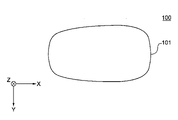
- FIG. 1A is a schematic front view of the flavor aspirator 100 according to the present embodiment.
- FIG. 1B is a schematic top view of the flavor aspirator 100 according to the present embodiment.
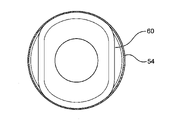
- FIG. 1C is a schematic bottom view of the flavor aspirator 100 according to the present embodiment.
- an XYZ Cartesian coordinate system may be added for convenience of explanation. In this coordinate system, the Z-axis points vertically upward, the XY planes are arranged to cut the flavor aspirator 100 horizontally, and the Y-axis extends from the front to the back of the flavor aspirator 100. It is arranged to be put out.
- the Z-axis can also be said to be the insertion direction of the flavor-generating article housed in the chamber 50 of the atomization unit 30, which will be described later, or the axial direction of the chamber 50.
- the X-axis may be a direction orthogonal to the Y-axis and the Z-axis, and the X-axis and the Y-axis may be a radial direction orthogonal to the axial direction or a radial direction of the chamber 50.
- the flavor aspirator 100 is configured to generate an aerosol containing an aerosol by heating, for example, a stick-type flavor generating article having a flavor source containing an aerosol source.
- the flavor aspirator 100 includes an outer housing 101 (corresponding to an example of the housing), a slide cover 102, and a switch portion 103.
- the outer housing 101 constitutes the outermost housing of the flavor aspirator 100 and has a size that fits in the user's hand. When the user uses the flavor aspirator 100, the flavor aspirator 100 can be held by hand to suck the aerosol.
- the outer housing 101 may be configured by assembling a plurality of members.
- the outer housing 101 is made of, for example, a resin, and in particular, polycarbonate (PC), ABS (Acrylonitrile-Butadiene-Stylene) resin, PEEK (polyetheretherketone), a polymer alloy containing a plurality of types of polymers, or the like, or aluminum. It can be made of a metal such as.
- PC polycarbonate
- ABS Acrylonitrile-Butadiene-Stylene
- PEEK polyetheretherketone
- the outer housing 101 has an opening (not shown) for receiving the flavor-generating article, and the slide cover 102 is slidably attached to the outer housing 101 so as to close this opening.
- the slide cover 102 is outside the outer housing 101 between a closed position (position shown in FIGS. 1A and 1B) for closing the opening of the outer housing 101 and an open position for opening the opening. It is configured to be movable along the surface. For example, the user can manually operate the slide cover 102 to move the slide cover 102 between the closed position and the open position. Thereby, the access of the flavor generating article to the inside of the slide cover 102 and the flavor aspirator 100 can be permitted or restricted.
- the switch unit 103 is used to switch the operation of the flavor aspirator 100 on and off. For example, by operating the switch unit 103 with the flavor-generating article inserted into the flavor-generating article 100, electric power is supplied to a heater (not shown) from a power source (not shown) to heat the flavor-generating article without burning it. be able to.
- the switch unit 103 may be a switch provided outside the outer housing 101, or may be a switch located inside the outer housing 101. When the switch is located inside the outer housing 101, the switch is indirectly pressed by pressing the switch portion 103 on the surface of the outer housing 101. In this embodiment, an example in which the switch of the switch unit 103 is located inside the outer housing 101 will be described.
- the flavor aspirator 100 may further have a terminal (not shown).
- the terminal may be an interface that connects the flavor aspirator 100 to, for example, an external power source.
- the power source included in the flavor aspirator 100 is a rechargeable battery
- the external power source can pass a current through the power source to charge the power source.
- data transmission cable to the terminal, data related to the operation of the flavor aspirator 100 may be transmitted to an external device.
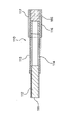
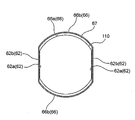
- FIG. 2 is a schematic side sectional view of the flavor generating article 110.
- the smoking system can be configured by the flavor aspirator 100 and the flavor generating article 110.
- the flavor generating article 110 includes a smokeable substance 111, a tubular member 114, a hollow filter portion 116, and a filter portion 115.
- the smokeable material 111 is wrapped by the first wrapping paper 112.
- the tubular member 114, the hollow filter portion 116, and the filter portion 115 are wound by a second roll paper 113 different from the first roll paper 112.
- the second wrapping paper 113 also wraps a part of the first wrapping paper 112 that wraps the smokeable material 111.
- the cylindrical member 114, the hollow filter portion 116, and the filter portion 115 are connected to the smokeable substance 111.
- the second wrapping paper 113 may be omitted, and the tubular member 114, the hollow filter portion 116, and the filter portion 115 and the smokeable material 111 may be connected by using the first wrapping paper 112.
- a lip release agent 117 for facilitating the separation of the user's lips from the second wrapping paper 113 is applied to the outer surface of the second wrapping paper 113 near the end portion on the filter portion 115 side.
- the portion of the flavor-generating article 110 to which the lip release agent 117 is applied functions as a mouthpiece of the flavor-generating article 110.
- the smokeable substance 111 may include, for example, a flavor source such as tobacco and an aerosol source.
- the first wrapping paper 112 around which the smokeable material 111 is wrapped may be a breathable sheet member.
- the tubular member 114 can be a paper tube or a hollow filter.
- the flavor generating article 110 includes a smokeable substance 111, a tubular member 114, a hollow filter portion 116, and a filter portion 115, but the configuration of the flavor generating article 110 is not limited to this.
- the hollow filter portion 116 may be omitted, and the cylindrical member 114 and the filter portion 115 may be arranged adjacent to each other.
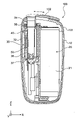
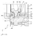
- FIG. 3 is a cross-sectional view of the flavor aspirator 100 in the arrow view 3-3 shown in FIG. 1B.
- an inner housing 10 (corresponding to an example of the housing) is provided inside the outer housing 101 of the flavor aspirator 100.
- the inner housing 10 is made of, for example, a resin, and in particular, a polycarbonate (PC), an ABS (Acrylonitrile-Butadie-Style) resin, a PEEK (polyetheretherketone), a polymer alloy containing a plurality of kinds of polymers, or the like, or It can be made of metal such as aluminum. From the viewpoint of heat resistance and strength, the inner housing 10 is preferably PEEK.
- a power supply unit 20 and an atomizing unit 30 are provided in the internal space of the inner housing 10.
- the power supply unit 20 has a power supply 21.
- the power source 21 may be, for example, a rechargeable battery or a non-rechargeable battery.
- the power supply 21 is electrically connected to the atomizing unit 30. As a result, the power supply 21 can supply electric power to the atomizing unit 30 so as to appropriately heat the flavor generating article 110.
- the atomizing portion 30 includes a metal chamber 50 (corresponding to an example of a cylindrical portion) extending in the insertion direction (Z-axis direction) of the flavor generating article 110, and a heater covering a part of the chamber 50. It has a 40, a heat insulating portion 32, and a substantially cylindrical insertion guide member 34 (corresponding to an example of the guide portion) that abuts on the opening 52 (see FIG. 4A) of the chamber 50.
- the chamber 50 is configured to surround the flavor generating article 110.
- the heater 40 is configured to include a heating unit 42 (see FIG. 6) that contacts the outer peripheral surface of the chamber 50 and heats the flavor generating article 110 inserted into the chamber 50.
- a bottom member 36 (corresponding to an example of the contact portion) is provided at the bottom of the chamber 50.
- the bottom member 36 may come into contact with the flavor generating article 110 inserted into the chamber 50 in the insertion direction of the flavor generating article 110 and function as a stopper for positioning the flavor generating article 110.
- the chamber 50 and the bottom member 36 constitute an accommodating portion for accommodating at least a part of the flavor generating article 110.
- the bottom member 36 can be formed of, for example, a resin material.
- the bottom member 36 has irregularities on the surface to which the flavor generating article 110 abuts, and air can be supplied to the air intake port of the flavor generating article 110 to which the flavor generating article 110 abuts, that is, the flavor contained in the accommodating portion.
- the bottom member 36 is made of, for example, a resin, and in particular, polycarbonate (PC), ABS (Acrylonitrile-Butadie-Style) resin, PEEK (polyetheretherketone), a polymer alloy containing a plurality of types of polymers, or the like, or aluminum. It can be made of metal such as.
- the bottom member 36 is preferably made of a material having a low thermal conductivity in order to suppress heat transfer to the heat insulating portion 32 and the like.
- the accommodating portion By forming the accommodating portion with the chamber 50 and the bottom member 36 formed of a member different from the chamber 50, the accommodating portion is formed by combining the bottom member 36, which has been finely processed in advance, with the chamber 50. can do. Therefore, it is possible to obtain a flavor aspirator 100 having a storage portion having a desired fine shape, which is highly processable and inexpensive. Further, since the bottom member 36 is made of resin, high workability can be realized, so that the first air flow path can be precisely designed.
- the heat insulating portion 32 has a substantially cylindrical shape as a whole, and is arranged so as to cover the chamber 50.
- the heat insulating portion 32 may include, for example, an airgel sheet.
- the insertion guide member 34 is provided between the slide cover 102 in the closed position and the chamber 50.
- the insertion guide member 34 is made of, for example, a resin, and is particularly formed of a polycarbonate (PC), an ABS (Acrylonitrile-Butagene-Stylene) resin, a PEEK (polyetheretherketone), a polymer alloy containing a plurality of types of polymers, or the like. obtain.
- the insertion guide member 34 may be made of metal, glass, ceramic, or the like.
- the insertion guide member 34 is preferably PEEK.
- the insertion guide member 34 communicates with the outside of the flavor aspirator 100 when the slide cover 102 is in the open position, and the flavor generating article 110 is inserted into the insertion guide member 34 to insert the flavor generating article 110 into the chamber 50. Guide the insertion of. By providing the insertion guide member 34, the flavor generating article 110 can be easily inserted into the chamber 50.
- the flavor aspirator 100 further has a first holding portion 37 and a second holding portion 38 that hold both ends of the chamber 50 and the heat insulating portion 32.
- the first holding portion 37 is arranged so as to hold the ends of the chamber 50 and the heat insulating portion 32 on the negative side of the Z axis.
- the second holding portion 38 is arranged so as to hold the ends of the chamber 50 and the heat insulating portion 32 on the slide cover 102 side (Z-axis positive direction side). Details of the first holding portion 37 and the second holding portion 38 will be described later.
- FIG. 4A is a perspective view of the chamber 50.
- FIG. 4B is a cross-sectional view of the chamber 50 in the arrow view 4B-4B shown in FIG. 4A.
- FIG. 5A is a cross-sectional view of the chamber 50 in the arrow view 5A-5A shown in FIG. 4B.
- FIG. 5B is a cross-sectional view of the chamber 50 in the arrow view 5B-5B shown in FIG. 4B.
- FIG. 6 is a perspective view of the chamber 50 and the heater 40.
- the chamber 50 can be a tubular member including an opening 52 into which the flavor generating article 110 is inserted and a tubular side wall portion 60 for accommodating the flavor generating article 110.
- a flange portion 52a is formed at the end portion defining the opening 52 of the chamber 50.
- the chamber 50 is preferably made of a material having heat resistance and a low coefficient of thermal expansion, and may be made of, for example, stainless steel.
- the chamber 50 may be made of a resin such as PEEK, glass, ceramic, or the like, in addition to metal. This enables effective heating from the chamber 50 to the flavor generating article 110.
- the side wall portion 60 includes a contact portion 62 and a separation portion 66.
- the contact portion 62 contacts or presses against and separates from a portion of the flavor-generating article 110 at a surface intersecting the insertion direction of the flavor-generating article 110.
- the unit 66 is separated from the flavor generating article 110.
- the "desired position in the chamber 50" means a position where the flavor generating article 110 is appropriately heated, or a position of the flavor generating article 110 when the user smokes.
- the side wall portion 60 includes the contact portion 62 and the separation portion 66, the cross-sectional shape of the side wall portion 60 orthogonal to the axial direction of the chamber 50 has an elliptical shape, that is, a non-cylindrical shape.
- the accommodating portion is composed of the chamber 50 and the bottom member 36 formed of a member different from the chamber 50, even if the chamber 50 has a deformed shape such as an elliptical shape or a square tube shape, the chamber is formed.
- the bottom member 36 can be finely processed regardless of the shape of the 50, and the workability of the accommodating portion can be improved.
- the contact portion 62 has an inner surface 62a and an outer surface 62b.
- the separating portion 66 has an inner surface 66a and an outer surface 66b.
- the heater 40 is arranged on the outer surface 62b of the contact portion 62. As a result, the heat generated in the heating portion 42 of the heater 40 is transferred to the flavor generating article 110 in contact with the contact portion 62. It is preferable that the heater 40 is arranged without a gap on the outer surface 62b of the contact portion 62.
- the heater 40 may include an adhesive layer. In that case, it is preferable that the heater 40 including the adhesive layer is arranged without a gap on the outer surface 62b of the contact portion 62.
- the outer surface 62b of the contact portion 62 is a flat surface. Since the outer surface 62b of the contact portion 62 is flat, the strip-shaped electrode 48 is flexed when the strip-shaped electrode 48 is connected to the heater 40 arranged on the outer surface 62b of the contact portion 62 as shown in FIG. It is possible to suppress swelling. As shown in FIGS. 4B and 5B, the inner surface 62a of the contact portion 62 is a flat surface. Further, as shown in FIGS. 4B and 5B, the thickness of the contact portion 62 is uniform.
- the chamber 50 has two contact portions 62 in the circumferential direction of the chamber 50, and the two contact portions 62 face each other so as to be parallel to each other. It is preferable that at least a part of the distance between the inner surfaces 62a of the two contact portions 62 is smaller than the width of the portion arranged between the contact portions 62 of the flavor generating article 110 inserted into the chamber 50.
- the inner surface 66a of the separation portion 66 may have an overall arcuate cross section in a plane orthogonal to the longitudinal direction (Z-axis direction) of the chamber 50. Further, the separating portion 66 is arranged so as to be adjacent to the contact portion 62 in the circumferential direction.
- the chamber 50 may have a hole 56a in its bottom 56 such that the bottom member 36 shown in FIG. 3 penetrates and is placed inside the chamber 50.
- the bottom member 36 may be fixed to the inside of the bottom 56 of the chamber 50 with an adhesive or the like.
- the adhesive can serve as a seal that seals between the chamber 50 and the bottom member 36.
- the adhesive interposed between the bottom member 36 and the bottom 56 may be made of a resin material such as an epoxy resin. Alternatively, an inorganic adhesive such as cement or welding may be used. As a result, the chamber 50 and the bottom member 36 are firmly fixed to each other, and the robustness can be enhanced.
- the bottom member 36 provided on the bottom 56 supports a part of the flavor generating article 110 inserted into the chamber 50 so as to expose at least a part of the end face of the flavor generating article 110. Further, the bottom portion 56 may support a part of the flavor generating article 110 so that the end face of the exposed flavor generating article 110 communicates with the void 67 (see FIG. 7) described later.
- the chamber 50 preferably has a cylindrical non-holding portion 54 between the opening 52 and the side wall portion 60. With the flavoring article 110 positioned at the desired position in the chamber 50, a gap may be formed between the non-holding portion 54 and the flavoring article 110. Further, as shown in FIGS. 4A and 4B, it is preferable that the chamber 50 has a first guide portion 58 provided with a tapered surface 58a connecting the inner surface of the non-holding portion 54 and the inner surface 62a of the contact portion 62.
- the heater 40 has a heating unit 42.
- the heating unit 42 may be, for example, a heating track. It is preferable that the heating portion 42 is arranged so as to heat the contact portion 62 without contacting the separation portion 66 of the chamber 50. In other words, it is preferable that the heating portion 42 is arranged only on the outer surface of the contact portion 62.
- the heating unit 42 may have a difference in heating capacity between the portion that heats the separation portion 66 of the chamber 50 and the portion that heats the contact portion 62. Specifically, the heating portion 42 may be configured to heat the contact portion 62 to a higher temperature than the separation portion 66. For example, the arrangement density of the heating track of the heating portion 42 in the contact portion 62 and the separation portion 66 can be adjusted. Further, the heating unit 42 may have substantially the same heating capacity on the entire circumference of the chamber 50 and may be wound around the outer periphery of the chamber 50.
- the heater 40 has an electric insulating member 44 that covers at least one surface of the heating unit 42 in addition to the heating unit 42.
- the electrical insulating member 44 is arranged so as to cover both sides of the heating portion 42.
- the bottom member 36 may be arranged so as not to overlap the heating portion 42 in the axial direction of the chamber 50. As a result, the heat from the heating portion 42 is less likely to be transferred to the bottom member 36, and deterioration of the bottom member 36 due to heat can be suppressed.
- FIG. 7 is a cross-sectional view shown in FIG. 5B in a state where the flavor generating article 110 is arranged at a desired position in the chamber 50.
- the flavor generating article 110 when the flavor generating article 110 is placed at a desired position in the chamber 50, the flavor generating article 110 can come into contact with and be pressed against the contact portion 62 of the chamber 50.
- a gap 67 is formed between the flavor generating article 110 and the separation portion 66.
- the void 67 can communicate with the opening 52 of the chamber 50 and the end face of the flavor generating article 110 located in the chamber 50.
- the air flowing in from the opening 52 of the chamber 50 can pass through the void 67 and flow into the inside of the flavor generating article 110.
- a second air flow path (void 67) is formed between the flavor generating article 110 and the separating portion 66.
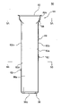
- FIG. 8 is a perspective view showing an air flow path of the flavor aspirator according to the present embodiment.
- the flavor generating article 110 is not shown.
- the second air flow path 150 formed between the flavor generating article 110 and the separating portion 66 communicates with the first air flow path 160 formed in the bottom member 36, and the first air flows.
- the flow path 160 communicates with a third air flow path 170 that passes through the inside of the flavor generating article 110.
- the air introduced into the accommodating portion is supplied to the flavor generating article 110 through the second air flow path 150 and the first air flow path 160, and can reach the user's mouth, so that the flavor is generated. It is not necessary to separately provide the flavor aspirator 100 with a flow path for introducing the air supplied to the article 110. Therefore, the structure of the flavor aspirator 100 can be simplified and the flavor aspirator 100 can be downsized.
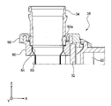
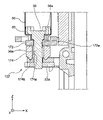
- FIG. 9 is an enlarged cross-sectional view of the first holding portion 37.
- FIG. 10 is an enlarged cross-sectional view of the second holding portion 38.
- the heat insulating portion 32 covering the chamber 50 is completely fixed to the inner housing 10 or the outer housing 101, when an external impact is applied to the flavor aspirator 100, the impact cannot be buffered. There is a risk that the heat insulating portion 32 will be destroyed. Further, when the heat insulating portion 32 expands due to the heat of the chamber 50 (or the heater 40), the fixed heat insulating portion 32 may buckle due to the thermal expansion.
- the first holding portion 37 and the second holding portion 38 have the heat insulating portion 32 in the axial direction of the chamber 50 or in the radial direction of the chamber 50 orthogonal to the axial direction (for example, the X-axis direction or the Y-axis). Hold it movable in the direction).
- the first holding portion 37 and the second holding portion 38 may hold the heat insulating portion 32 so as to be movable only in the axial direction of the chamber 50, or hold the heat insulating portion 32 so as to be movable only in the radial direction orthogonal to the axial direction. You may.
- the bottom member 36 engages with the bottom 56 of the chamber 50. Thereby, the bottom member 36 can be positioned and supported in the chamber 50. Further, the bottom member 36 provided inside the bottom portion 56 of the chamber 50 has a shaft portion 36a protruding to the outside of the chamber 50 through the hole 56a of the chamber 50. Further, the shaft portion 36a has a flat surface 36b (corresponding to an example of the rotation prevention mechanism) at the end portion.
- the first holding portion 37 has a support portion 72, a heater cushion 74 (corresponding to an example of the first regulating portion and one end side regulating portion), and a ring 85 (corresponding to an example of the second regulating portion). ..
- the support portion 72 is configured to receive the shaft portion 36a of the bottom member 36 and support the chamber 50. Specifically, the bottom portion 56 of the chamber 50 is sandwiched and supported by the bottom member 36 and the support portion 72.
- the support portion 72 is made of, for example, a resin, and may be formed of, in particular, a polycarbonate (PC), an ABS (Acrylonitrile-Butadie-Style) resin, a PEEK (polyetheretherketone), a polymer alloy containing a plurality of types of polymers, or the like. ..
- the support portion 72 may be made of metal, glass, ceramic, or the like. Further, from the viewpoint of heat resistance, the support portion 72 is preferably PEEK.
- the chamber 50 specifically the bottom portion 56 of the chamber 50, is sandwiched and supported by the bottom member 36 and the support portion 72 that engages with the bottom member 36. Therefore, the chamber 50 is firmly fixed and the robustness can be enhanced.
- the support portion 72 has a flat surface 72a (corresponding to an example of the rotation prevention mechanism) so as to face the flat surface 36b of the shaft portion 36a.
- the bottom member 36 forms an air layer 36d on the opposite side of the contact surface 36c that comes into contact with the flavor generating article 110 accommodated in the accommodating portion in a state of being engaged with the support portion 72. That is, the bottom member 36 does not come into direct contact with the heater cushion 74. Therefore, heat loss due to heat transfer from the bottom member 36 can be suppressed.
- the heater cushion 74 is configured to accommodate and support one end of the support portion 72.
- the heater cushion 74 may be formed of an elastic member such as silicone rubber. When silicone rubber is used, the suitable range of shore A hardness is 40 to 60, and it can be appropriately selected according to the deformation of the heater cushion 74. Further, the heater cushion 74 is configured to be positioned and fixed to a fixing portion 22 fixed to an inner housing (not shown). The fixing portion 22 may be the inner housing itself.
- the heater cushion 74 is formed of an elastic member such as silicon, and is configured to urge the chamber 50 to the insertion guide member 34 via the support portion 72, that is, to urge the insertion guide member 34 in the positive direction of the Z axis. To. As a result, a seal is formed between the flange portion 52a of the chamber 50 and the insertion guide member 34, so that the aerosol generated in the chamber 50 by heating the flavor generating article 110 is between the chamber 50 and the insertion guide member 34. It is possible to prevent leakage from the inside of the inner chamber.
- the heater cushion 74 is arranged so as to face the heat insulating portion 32 with a gap, and restricts the movement of the heat insulating portion 32 in the axial direction of the chamber 50. Therefore, since the heat insulating portion 32 is prevented from moving endlessly in the axial direction of the chamber 50, the heat insulating portion 32 is prevented from colliding with another member (for example, the inner housing 10 or the like). Further, since the heater cushion 74 is formed of an elastic member, even when the heater cushion 74 comes into contact with the heat insulating portion 32, the stress applied to the heat insulating portion 32 can be relieved, so that the heat insulating portion 32 is destroyed. It can be prevented from being done.
- the ring 85 has an opening 85a into which the support portion 72 is inserted, and can be sandwiched and fixed between the support portion 72 and the heater cushion 74.
- the ring 85 is made of, for example, a resin and may be formed, in particular, from polycarbonate (PC), ABS (Acrylonitrile-Butadie-Style) resin, PEEK (polyetheretherketone), a polymer alloy containing a plurality of polymers, and the like.
- the ring 85 may be made of metal, glass, ceramic or the like. Further, from the viewpoint of heat resistance, the ring 85 is preferably PEEK.
- the ring 85 is arranged so as to face the support member 32a provided on the inner peripheral surface of the heat insulating portion 32 with a gap, and restricts the movement of the heat insulating portion 32 in the radial direction of the chamber 50. Therefore, since the heat insulating portion 32 is prevented from moving endlessly in the radial direction of the chamber 50, the heat insulating portion 32 is prevented from colliding with another member (for example, the inner housing 10 or the like). Further, since the movement of the heat insulating portion 32 in the radial direction of the chamber 50 can be restricted from the inside of the heat insulating portion 32, the flavor aspirator 100 can be miniaturized.
- the heat insulating portion 32 has a support material 32a and a heat insulating layer 32b provided on the outer peripheral surface of the support material 32a.
- the support member 32a has, for example, a substantially cylindrical shape, and is arranged so as to surround the chamber 50.
- the support material 32a is made of, for example, a resin, and may be particularly formed of a polycarbonate (PC), an ABS (Acrylonitrile-Butagene-Stylene) resin, a PEEK (polyetheretherketone), a polymer alloy containing a plurality of types of polymers, or the like. ..
- the heat insulating layer 32b can be, for example, an airgel sheet.
- the support material 32a is formed thinner than the heat insulating layer 32b and has a thickness of 1 mm or less, preferably 0.5 mm or less. As a result, the heat capacity of the heat insulating portion 32 itself can be reduced, so that the heat loss in the heat insulating portion 32 can be suppressed.
- the flange portion 52a of the chamber 50 is configured to come into contact with the insertion guide member 34 over the entire circumference.
- the second holding portion 38 has a gasket 80 (corresponding to an example of the cover portion) and an annular member 90 (corresponding to an example of the cover portion).
- the gasket 80 is arranged around the non-holding portion 54 of the chamber 50 and is configured to support the chamber 50.
- the gasket 80 is made of, for example, a resin, and may be formed of, in particular, a polycarbonate (PC), an ABS (Acrylonitrile-Butadiene-Style) resin, a PEEK (polyetheretherketone), a polymer alloy containing a plurality of polymers, and the like.
- the gasket 80 may be made of metal, glass, ceramic or the like. Further, from the viewpoint of heat resistance, the gasket 80 is preferably PEEK.
- the annular member 90 is configured to engage and support the insertion guide member 34 and the gasket 80.
- the annular member 90 can be formed of an elastic member such as silicone rubber.
- the suitable range of shore A hardness is 40 to 60, and it can be appropriately selected according to the deformation of the annular member 90. Further, the annular member 90 is configured to be positioned and fixed to a fixing portion 22 fixed to an inner housing (not shown).
- the gasket 80 and the annular member 90 are arranged so as to cover the periphery of the contact portion between the chamber 50 and the insertion guide member 34. As a result, it is possible to prevent the aerosol generated in the chamber 50 from leaking into the inner housing of the flavor aspirator 100 from the contact portion between the chamber 50 and the insertion guide member 34.
- the gasket 80 and the annular member 90 are arranged so as to face each other with a gap from the heat insulating portion 32, and restrict the movement of the heat insulating portion 32 in the axial direction of the chamber 50. Therefore, since the heat insulating portion 32 is prevented from moving endlessly in the axial direction of the chamber 50, the heat insulating portion 32 is prevented from colliding with another member (for example, the inner housing 10 or the like). Further, since the annular member 90 is formed of an elastic member, even when the annular member 90 comes into contact with the heat insulating portion 32, the stress applied to the heat insulating portion 32 can be relaxed, so that the heat insulating portion 32 can be relaxed. Can be prevented from being destroyed.
- the gasket 80 is arranged so as to face the inner peripheral surface of the heat insulating portion 32 with a gap, and restricts the movement of the heat insulating portion 32 in the radial direction of the chamber 50. Therefore, since the heat insulating portion 32 is prevented from moving endlessly in the radial direction of the chamber 50, the heat insulating portion 32 is prevented from colliding with another member (for example, the inner housing 10 or the like). Further, since the movement of the heat insulating portion 32 in the radial direction of the chamber 50 can be restricted from the inside of the heat insulating portion 32, the flavor aspirator 100 can be miniaturized.
- the distance between the heater cushion 74 and the gasket 80 and the annular member 90 is defined as L1 to insulate.
- L1 the distance between the heater cushion 74 and the gasket 80 and the annular member 90 at a position facing the heat insulating portion 32.
- FIG. 11 is an enlarged cross-sectional view showing another form of the first holding portion.
- the first holding portion 137 has a ring 172 (corresponding to an example of the support portion) and a heater cushion 174.
- the bottom member 36 provided in the bottom portion 56 of the chamber 50 has a shaft portion 36a protruding to the outside of the chamber 50 through the hole 56a of the chamber 50.
- the ring 172 is configured to abut on the bottom 56 of the chamber 50 to support the chamber 50. Further, the ring 172 has a hole 172a in the central portion through which the shaft portion 36a of the bottom member 36 penetrates.
- the ring 172 is made of, for example, a resin, and in particular, a resin such as PEEK from a polymer alloy containing polycarbonate (PC), ABS (Acrylonitrile-Butadiene-Stylerene) resin, PEEK (polyetheretherketone), or a plurality of types of polymers. Can be formed with.
- the heater cushion 174 is configured to accommodate and support one end of the ring 172. Further, the heater cushion 174 has a hole 174a in the central portion through which the shaft portion 36a of the bottom member 36 penetrates.
- the heater cushion 174 can be formed of an elastic member such as silicon.
- the bottom member 36 is configured such that the shaft portion 36a is positioned and fixed to a fixing portion 22 fixed to an inner housing (not shown).
- the fixing portion 22 may be the inner housing itself.
- the heater cushion 174 urges the chamber 50 to the insertion guide member 34, so that a seal is formed between the flange portion 52a of the chamber 50 and the insertion guide member 34. Since it is formed, it is possible to prevent the aerosol generated in the chamber 50 by heating the flavor generating article 110 from leaking into the inner housing from between the chamber 50 and the insertion guide member 34.
- the flavor aspirator 100 of the present embodiment has a so-called counterflow type air flow path in which the air flowing in from the opening 52 of the chamber 50 is supplied to the end face of the flavor generating article 110, but the present invention is not limited to this. It may have a so-called bottom flow type air flow path in which air is supplied from the bottom 56 of the chamber 50 into the chamber 50.
- the heating unit 42 is not limited to the resistance heating type, but may be an induction heating type. In that case, the heating unit 42 can heat the chamber 50 by induction heating. Further, when the flavor-generating article 110 has a susceptor, the heating unit 42 can heat the susceptor of the flavor-generating article 110 by induction heating.
Landscapes
- Packages (AREA)
- Apparatus For Making Beverages (AREA)
- Disinfection, Sterilisation Or Deodorisation Of Air (AREA)
- Medicinal Preparation (AREA)
- Details Of Rigid Or Semi-Rigid Containers (AREA)
Abstract
Priority Applications (7)
| Application Number | Priority Date | Filing Date | Title |
|---|---|---|---|
| CN202080107802.6A CN116600668A (zh) | 2020-12-11 | 2020-12-11 | 香味吸取器 |
| PCT/JP2020/046198 WO2022123760A1 (fr) | 2020-12-11 | 2020-12-11 | Inhalateur d'arôme |
| JP2022568001A JPWO2022123760A1 (fr) | 2020-12-11 | 2020-12-11 | |
| KR1020237021298A KR20230111232A (ko) | 2020-12-11 | 2020-12-11 | 향미 흡인기 |
| EP20965142.1A EP4260725A1 (fr) | 2020-12-11 | 2020-12-11 | Inhalateur d'arôme |
| TW110122593A TWI841851B (zh) | 2020-12-11 | 2021-06-21 | 香味吸嚐器 |
| US18/325,630 US20230301357A1 (en) | 2020-12-11 | 2023-05-30 | Flavor inhaler |
Applications Claiming Priority (1)
| Application Number | Priority Date | Filing Date | Title |
|---|---|---|---|
| PCT/JP2020/046198 WO2022123760A1 (fr) | 2020-12-11 | 2020-12-11 | Inhalateur d'arôme |
Related Child Applications (1)
| Application Number | Title | Priority Date | Filing Date |
|---|---|---|---|
| US18/325,630 Continuation US20230301357A1 (en) | 2020-12-11 | 2023-05-30 | Flavor inhaler |
Publications (1)
| Publication Number | Publication Date |
|---|---|
| WO2022123760A1 true WO2022123760A1 (fr) | 2022-06-16 |
Family
ID=81974316
Family Applications (1)
| Application Number | Title | Priority Date | Filing Date |
|---|---|---|---|
| PCT/JP2020/046198 WO2022123760A1 (fr) | 2020-12-11 | 2020-12-11 | Inhalateur d'arôme |
Country Status (6)
| Country | Link |
|---|---|
| US (1) | US20230301357A1 (fr) |
| EP (1) | EP4260725A1 (fr) |
| JP (1) | JPWO2022123760A1 (fr) |
| KR (1) | KR20230111232A (fr) |
| CN (1) | CN116600668A (fr) |
| WO (1) | WO2022123760A1 (fr) |
Cited By (1)
| Publication number | Priority date | Publication date | Assignee | Title |
|---|---|---|---|---|
| WO2024100781A1 (fr) * | 2022-11-09 | 2024-05-16 | 日本たばこ産業株式会社 | Inhalateur d'arôme et système d'inhalation d'arôme |
Citations (3)
| Publication number | Priority date | Publication date | Assignee | Title |
|---|---|---|---|---|
| US20200008477A1 (en) * | 2018-07-05 | 2020-01-09 | Shenzhen Ivps Technology Co., Ltd. | Electronic cigarette |
| WO2020074612A1 (fr) | 2018-10-12 | 2020-04-16 | Jt International S.A. | Dispositif de génération d'aérosol et chambre de chauffage associée |
| JP2020516267A (ja) * | 2017-04-11 | 2020-06-11 | ケーティー・アンド・ジー・コーポレーション | エアロゾル生成装置 |
Family Cites Families (1)
| Publication number | Priority date | Publication date | Assignee | Title |
|---|---|---|---|---|
| JP6519479B2 (ja) | 2013-11-15 | 2019-05-29 | 日本電気株式会社 | 周波数偏差補償方式および周波数偏差補償方法 |
-
2020
- 2020-12-11 WO PCT/JP2020/046198 patent/WO2022123760A1/fr active Application Filing
- 2020-12-11 KR KR1020237021298A patent/KR20230111232A/ko unknown
- 2020-12-11 CN CN202080107802.6A patent/CN116600668A/zh active Pending
- 2020-12-11 EP EP20965142.1A patent/EP4260725A1/fr active Pending
- 2020-12-11 JP JP2022568001A patent/JPWO2022123760A1/ja active Pending
-
2023
- 2023-05-30 US US18/325,630 patent/US20230301357A1/en active Pending
Patent Citations (3)
| Publication number | Priority date | Publication date | Assignee | Title |
|---|---|---|---|---|
| JP2020516267A (ja) * | 2017-04-11 | 2020-06-11 | ケーティー・アンド・ジー・コーポレーション | エアロゾル生成装置 |
| US20200008477A1 (en) * | 2018-07-05 | 2020-01-09 | Shenzhen Ivps Technology Co., Ltd. | Electronic cigarette |
| WO2020074612A1 (fr) | 2018-10-12 | 2020-04-16 | Jt International S.A. | Dispositif de génération d'aérosol et chambre de chauffage associée |
Cited By (1)
| Publication number | Priority date | Publication date | Assignee | Title |
|---|---|---|---|---|
| WO2024100781A1 (fr) * | 2022-11-09 | 2024-05-16 | 日本たばこ産業株式会社 | Inhalateur d'arôme et système d'inhalation d'arôme |
Also Published As
| Publication number | Publication date |
|---|---|
| KR20230111232A (ko) | 2023-07-25 |
| CN116600668A (zh) | 2023-08-15 |
| US20230301357A1 (en) | 2023-09-28 |
| TW202222183A (zh) | 2022-06-16 |
| JPWO2022123760A1 (fr) | 2022-06-16 |
| EP4260725A1 (fr) | 2023-10-18 |
Similar Documents
| Publication | Publication Date | Title |
|---|---|---|
| WO2022123757A1 (fr) | Inhalateur de parfum | |
| US20210235761A1 (en) | Housing and flavor aspirator provided with same | |
| WO2022123760A1 (fr) | Inhalateur d'arôme | |
| JP2024057043A (ja) | 香味吸引器 | |
| WO2022123761A1 (fr) | Inhalateur d'arôme et procédé de réduction de pression | |
| WO2022123758A1 (fr) | Inhalateur d'arôme | |
| WO2022123759A1 (fr) | Inhalateur d'arôme et procédé de fabrication d'inhalateur d'arôme | |
| WO2024100781A1 (fr) | Inhalateur d'arôme et système d'inhalation d'arôme | |
| JP7298041B2 (ja) | 香味吸引器 | |
| JP7204918B2 (ja) | 加熱アセンブリおよび香味吸引器 | |
| WO2022123770A1 (fr) | Inhalateur d'arôme et procédé de production d'inhalateur d'arôme | |
| WO2022123754A1 (fr) | Inhalateur d'arôme | |
| WO2022224428A1 (fr) | Inhalateur d'arôme | |
| WO2023058220A1 (fr) | Inhalateur d'arôme | |
| WO2022123768A1 (fr) | Inhalateur d'arôme et procédé de fabrication d'un inhalateur d'arôme | |
| WO2022123766A1 (fr) | Inhalateur d'arôme et procédé de fabrication d'un inhalateur d'arôme | |
| US20240008530A1 (en) | Flavor inhaler and smoking system | |
| KR20230169225A (ko) | 향미 흡인기 |
Legal Events
| Date | Code | Title | Description |
|---|---|---|---|
| 121 | Ep: the epo has been informed by wipo that ep was designated in this application |
Ref document number: 20965142 Country of ref document: EP Kind code of ref document: A1 |
|
| ENP | Entry into the national phase |
Ref document number: 2022568001 Country of ref document: JP Kind code of ref document: A |
|
| WWE | Wipo information: entry into national phase |
Ref document number: 202080107802.6 Country of ref document: CN |
|
| ENP | Entry into the national phase |
Ref document number: 20237021298 Country of ref document: KR Kind code of ref document: A |
|
| NENP | Non-entry into the national phase |
Ref country code: DE |
|
| ENP | Entry into the national phase |
Ref document number: 2020965142 Country of ref document: EP Effective date: 20230711 |