WO2022118822A1 - 回転電機の駆動装置、駆動方法および鉄道車両 - Google Patents
回転電機の駆動装置、駆動方法および鉄道車両 Download PDFInfo
- Publication number
- WO2022118822A1 WO2022118822A1 PCT/JP2021/043765 JP2021043765W WO2022118822A1 WO 2022118822 A1 WO2022118822 A1 WO 2022118822A1 JP 2021043765 W JP2021043765 W JP 2021043765W WO 2022118822 A1 WO2022118822 A1 WO 2022118822A1
- Authority
- WO
- WIPO (PCT)
- Prior art keywords
- electric machine
- rotary electric
- value
- phase
- deviation
- Prior art date
Links
- 238000000034 method Methods 0.000 title claims description 40
- 230000001133 acceleration Effects 0.000 claims description 103
- 238000001514 detection method Methods 0.000 claims description 62
- 230000001360 synchronised effect Effects 0.000 claims description 28
- 230000006698 induction Effects 0.000 claims description 13
- 230000015572 biosynthetic process Effects 0.000 claims description 7
- 230000007423 decrease Effects 0.000 claims description 6
- 230000000087 stabilizing effect Effects 0.000 abstract description 11
- 238000010586 diagram Methods 0.000 description 28
- 230000000694 effects Effects 0.000 description 18
- 238000012545 processing Methods 0.000 description 14
- 238000012937 correction Methods 0.000 description 13
- 239000000853 adhesive Substances 0.000 description 8
- 230000001070 adhesive effect Effects 0.000 description 8
- 238000006243 chemical reaction Methods 0.000 description 8
- 230000008859 change Effects 0.000 description 6
- 230000004048 modification Effects 0.000 description 6
- 238000012986 modification Methods 0.000 description 6
- 230000003111 delayed effect Effects 0.000 description 4
- 239000000411 inducer Substances 0.000 description 4
- 230000008929 regeneration Effects 0.000 description 3
- 238000011069 regeneration method Methods 0.000 description 3
- 238000012546 transfer Methods 0.000 description 3
- 238000007796 conventional method Methods 0.000 description 2
- 230000002542 deteriorative effect Effects 0.000 description 2
- 230000004069 differentiation Effects 0.000 description 2
- 239000000428 dust Substances 0.000 description 2
- 230000010354 integration Effects 0.000 description 2
- 230000010363 phase shift Effects 0.000 description 2
- 230000008569 process Effects 0.000 description 2
- 230000009467 reduction Effects 0.000 description 2
- 230000003247 decreasing effect Effects 0.000 description 1
- 230000001687 destabilization Effects 0.000 description 1
- 230000006866 deterioration Effects 0.000 description 1
- 238000009499 grossing Methods 0.000 description 1
- 230000006872 improvement Effects 0.000 description 1
- 238000009940 knitting Methods 0.000 description 1
- 230000002093 peripheral effect Effects 0.000 description 1
- 230000004044 response Effects 0.000 description 1
- 230000002194 synthesizing effect Effects 0.000 description 1
- 230000001052 transient effect Effects 0.000 description 1
Images


Classifications
-
- B—PERFORMING OPERATIONS; TRANSPORTING
- B60—VEHICLES IN GENERAL
- B60L—PROPULSION OF ELECTRICALLY-PROPELLED VEHICLES; SUPPLYING ELECTRIC POWER FOR AUXILIARY EQUIPMENT OF ELECTRICALLY-PROPELLED VEHICLES; ELECTRODYNAMIC BRAKE SYSTEMS FOR VEHICLES IN GENERAL; MAGNETIC SUSPENSION OR LEVITATION FOR VEHICLES; MONITORING OPERATING VARIABLES OF ELECTRICALLY-PROPELLED VEHICLES; ELECTRIC SAFETY DEVICES FOR ELECTRICALLY-PROPELLED VEHICLES
- B60L15/00—Methods, circuits, or devices for controlling the traction-motor speed of electrically-propelled vehicles
- B60L15/02—Methods, circuits, or devices for controlling the traction-motor speed of electrically-propelled vehicles characterised by the form of the current used in the control circuit
- B60L15/025—Methods, circuits, or devices for controlling the traction-motor speed of electrically-propelled vehicles characterised by the form of the current used in the control circuit using field orientation; Vector control; Direct Torque Control [DTC]
-
- H—ELECTRICITY
- H02—GENERATION; CONVERSION OR DISTRIBUTION OF ELECTRIC POWER
- H02P—CONTROL OR REGULATION OF ELECTRIC MOTORS, ELECTRIC GENERATORS OR DYNAMO-ELECTRIC CONVERTERS; CONTROLLING TRANSFORMERS, REACTORS OR CHOKE COILS
- H02P21/00—Arrangements or methods for the control of electric machines by vector control, e.g. by control of field orientation
- H02P21/14—Estimation or adaptation of machine parameters, e.g. flux, current or voltage
- H02P21/18—Estimation of position or speed
-
- B—PERFORMING OPERATIONS; TRANSPORTING
- B60—VEHICLES IN GENERAL
- B60L—PROPULSION OF ELECTRICALLY-PROPELLED VEHICLES; SUPPLYING ELECTRIC POWER FOR AUXILIARY EQUIPMENT OF ELECTRICALLY-PROPELLED VEHICLES; ELECTRODYNAMIC BRAKE SYSTEMS FOR VEHICLES IN GENERAL; MAGNETIC SUSPENSION OR LEVITATION FOR VEHICLES; MONITORING OPERATING VARIABLES OF ELECTRICALLY-PROPELLED VEHICLES; ELECTRIC SAFETY DEVICES FOR ELECTRICALLY-PROPELLED VEHICLES
- B60L2200/00—Type of vehicles
- B60L2200/26—Rail vehicles
-
- B—PERFORMING OPERATIONS; TRANSPORTING
- B60—VEHICLES IN GENERAL
- B60L—PROPULSION OF ELECTRICALLY-PROPELLED VEHICLES; SUPPLYING ELECTRIC POWER FOR AUXILIARY EQUIPMENT OF ELECTRICALLY-PROPELLED VEHICLES; ELECTRODYNAMIC BRAKE SYSTEMS FOR VEHICLES IN GENERAL; MAGNETIC SUSPENSION OR LEVITATION FOR VEHICLES; MONITORING OPERATING VARIABLES OF ELECTRICALLY-PROPELLED VEHICLES; ELECTRIC SAFETY DEVICES FOR ELECTRICALLY-PROPELLED VEHICLES
- B60L2220/00—Electrical machine types; Structures or applications thereof
- B60L2220/10—Electrical machine types
- B60L2220/12—Induction machines
-
- B—PERFORMING OPERATIONS; TRANSPORTING
- B60—VEHICLES IN GENERAL
- B60L—PROPULSION OF ELECTRICALLY-PROPELLED VEHICLES; SUPPLYING ELECTRIC POWER FOR AUXILIARY EQUIPMENT OF ELECTRICALLY-PROPELLED VEHICLES; ELECTRODYNAMIC BRAKE SYSTEMS FOR VEHICLES IN GENERAL; MAGNETIC SUSPENSION OR LEVITATION FOR VEHICLES; MONITORING OPERATING VARIABLES OF ELECTRICALLY-PROPELLED VEHICLES; ELECTRIC SAFETY DEVICES FOR ELECTRICALLY-PROPELLED VEHICLES
- B60L2220/00—Electrical machine types; Structures or applications thereof
- B60L2220/10—Electrical machine types
- B60L2220/14—Synchronous machines
-
- B—PERFORMING OPERATIONS; TRANSPORTING
- B60—VEHICLES IN GENERAL
- B60L—PROPULSION OF ELECTRICALLY-PROPELLED VEHICLES; SUPPLYING ELECTRIC POWER FOR AUXILIARY EQUIPMENT OF ELECTRICALLY-PROPELLED VEHICLES; ELECTRODYNAMIC BRAKE SYSTEMS FOR VEHICLES IN GENERAL; MAGNETIC SUSPENSION OR LEVITATION FOR VEHICLES; MONITORING OPERATING VARIABLES OF ELECTRICALLY-PROPELLED VEHICLES; ELECTRIC SAFETY DEVICES FOR ELECTRICALLY-PROPELLED VEHICLES
- B60L2240/00—Control parameters of input or output; Target parameters
- B60L2240/10—Vehicle control parameters
- B60L2240/12—Speed
-
- B—PERFORMING OPERATIONS; TRANSPORTING
- B60—VEHICLES IN GENERAL
- B60L—PROPULSION OF ELECTRICALLY-PROPELLED VEHICLES; SUPPLYING ELECTRIC POWER FOR AUXILIARY EQUIPMENT OF ELECTRICALLY-PROPELLED VEHICLES; ELECTRODYNAMIC BRAKE SYSTEMS FOR VEHICLES IN GENERAL; MAGNETIC SUSPENSION OR LEVITATION FOR VEHICLES; MONITORING OPERATING VARIABLES OF ELECTRICALLY-PROPELLED VEHICLES; ELECTRIC SAFETY DEVICES FOR ELECTRICALLY-PROPELLED VEHICLES
- B60L2240/00—Control parameters of input or output; Target parameters
- B60L2240/40—Drive Train control parameters
- B60L2240/42—Drive Train control parameters related to electric machines
- B60L2240/421—Speed
-
- B—PERFORMING OPERATIONS; TRANSPORTING
- B60—VEHICLES IN GENERAL
- B60L—PROPULSION OF ELECTRICALLY-PROPELLED VEHICLES; SUPPLYING ELECTRIC POWER FOR AUXILIARY EQUIPMENT OF ELECTRICALLY-PROPELLED VEHICLES; ELECTRODYNAMIC BRAKE SYSTEMS FOR VEHICLES IN GENERAL; MAGNETIC SUSPENSION OR LEVITATION FOR VEHICLES; MONITORING OPERATING VARIABLES OF ELECTRICALLY-PROPELLED VEHICLES; ELECTRIC SAFETY DEVICES FOR ELECTRICALLY-PROPELLED VEHICLES
- B60L2240/00—Control parameters of input or output; Target parameters
- B60L2240/40—Drive Train control parameters
- B60L2240/42—Drive Train control parameters related to electric machines
- B60L2240/423—Torque
-
- B—PERFORMING OPERATIONS; TRANSPORTING
- B60—VEHICLES IN GENERAL
- B60L—PROPULSION OF ELECTRICALLY-PROPELLED VEHICLES; SUPPLYING ELECTRIC POWER FOR AUXILIARY EQUIPMENT OF ELECTRICALLY-PROPELLED VEHICLES; ELECTRODYNAMIC BRAKE SYSTEMS FOR VEHICLES IN GENERAL; MAGNETIC SUSPENSION OR LEVITATION FOR VEHICLES; MONITORING OPERATING VARIABLES OF ELECTRICALLY-PROPELLED VEHICLES; ELECTRIC SAFETY DEVICES FOR ELECTRICALLY-PROPELLED VEHICLES
- B60L2240/00—Control parameters of input or output; Target parameters
- B60L2240/40—Drive Train control parameters
- B60L2240/42—Drive Train control parameters related to electric machines
- B60L2240/427—Voltage
-
- B—PERFORMING OPERATIONS; TRANSPORTING
- B60—VEHICLES IN GENERAL
- B60L—PROPULSION OF ELECTRICALLY-PROPELLED VEHICLES; SUPPLYING ELECTRIC POWER FOR AUXILIARY EQUIPMENT OF ELECTRICALLY-PROPELLED VEHICLES; ELECTRODYNAMIC BRAKE SYSTEMS FOR VEHICLES IN GENERAL; MAGNETIC SUSPENSION OR LEVITATION FOR VEHICLES; MONITORING OPERATING VARIABLES OF ELECTRICALLY-PROPELLED VEHICLES; ELECTRIC SAFETY DEVICES FOR ELECTRICALLY-PROPELLED VEHICLES
- B60L2240/00—Control parameters of input or output; Target parameters
- B60L2240/40—Drive Train control parameters
- B60L2240/42—Drive Train control parameters related to electric machines
- B60L2240/429—Current
-
- B—PERFORMING OPERATIONS; TRANSPORTING
- B60—VEHICLES IN GENERAL
- B60L—PROPULSION OF ELECTRICALLY-PROPELLED VEHICLES; SUPPLYING ELECTRIC POWER FOR AUXILIARY EQUIPMENT OF ELECTRICALLY-PROPELLED VEHICLES; ELECTRODYNAMIC BRAKE SYSTEMS FOR VEHICLES IN GENERAL; MAGNETIC SUSPENSION OR LEVITATION FOR VEHICLES; MONITORING OPERATING VARIABLES OF ELECTRICALLY-PROPELLED VEHICLES; ELECTRIC SAFETY DEVICES FOR ELECTRICALLY-PROPELLED VEHICLES
- B60L2240/00—Control parameters of input or output; Target parameters
- B60L2240/40—Drive Train control parameters
- B60L2240/52—Drive Train control parameters related to converters
- B60L2240/526—Operating parameters
-
- B—PERFORMING OPERATIONS; TRANSPORTING
- B60—VEHICLES IN GENERAL
- B60L—PROPULSION OF ELECTRICALLY-PROPELLED VEHICLES; SUPPLYING ELECTRIC POWER FOR AUXILIARY EQUIPMENT OF ELECTRICALLY-PROPELLED VEHICLES; ELECTRODYNAMIC BRAKE SYSTEMS FOR VEHICLES IN GENERAL; MAGNETIC SUSPENSION OR LEVITATION FOR VEHICLES; MONITORING OPERATING VARIABLES OF ELECTRICALLY-PROPELLED VEHICLES; ELECTRIC SAFETY DEVICES FOR ELECTRICALLY-PROPELLED VEHICLES
- B60L2240/00—Control parameters of input or output; Target parameters
- B60L2240/40—Drive Train control parameters
- B60L2240/52—Drive Train control parameters related to converters
- B60L2240/529—Current
-
- Y—GENERAL TAGGING OF NEW TECHNOLOGICAL DEVELOPMENTS; GENERAL TAGGING OF CROSS-SECTIONAL TECHNOLOGIES SPANNING OVER SEVERAL SECTIONS OF THE IPC; TECHNICAL SUBJECTS COVERED BY FORMER USPC CROSS-REFERENCE ART COLLECTIONS [XRACs] AND DIGESTS
- Y02—TECHNOLOGIES OR APPLICATIONS FOR MITIGATION OR ADAPTATION AGAINST CLIMATE CHANGE
- Y02T—CLIMATE CHANGE MITIGATION TECHNOLOGIES RELATED TO TRANSPORTATION
- Y02T10/00—Road transport of goods or passengers
- Y02T10/60—Other road transportation technologies with climate change mitigation effect
- Y02T10/72—Electric energy management in electromobility
Definitions
- the present invention relates to a drive device, a drive method, and a railroad vehicle equipped with the rotary electric machine.
- wheels which are driving wheels, are rotated by the torque of a rotary electric machine, and the vehicle is accelerated by the tangential force generated in the wheels as a reaction force received from the rail by the wheel tread.
- This tangential force varies depending on the tangential force coefficient ⁇ that represents the adhesive state between the wheel and the rail, and when the wheel torque becomes excessive than the tangential force, the force that accelerates the vehicle remains small and the wheel is rotated. Only becomes larger, resulting in wheel slipping or slipping (hereinafter abbreviated as "sliding").
- sliding wheel slipping or slipping
- idling re-adhesion control is widely used in which the wheel is re-adhered to the rail by promptly detecting the idling slip that occurs between the wheel and the rail and narrowing down the torque of the rotary electric machine.
- control is performed in order to enable detection of idling or sliding of the drive shaft of the induction motor even when the relative speed of each induction motor is small without using a speed sensor.
- a technique is disclosed in which an acceleration estimated value ⁇ i is calculated from a time change (differential value) of a frequency command value of an apparatus, and when it is determined that a predetermined threshold value is exceeded, it is determined that slipping has occurred.
- Patent Document 2 it is proportional to the position error estimation value of the permanent magnet synchronous motor in order to reduce the delay of acceleration estimation due to the ⁇ , ⁇ -axis current and the vibration of the mechanical system, and the delay of idling gliding control.
- a technique for calculating an acceleration estimated value by adding a term and a differential value of a term proportional to the position error estimated value is disclosed.
- Patent Document 3 describes two points that the control becomes unstable due to the control gain being too large in the steady state against a sudden change in speed such as when idling, and the withstand of step-out is improved in the transient.
- a technique for making the sensorless control gain variable according to the rotation phase angle error is disclosed.
- Patent Document 1 calculates an acceleration estimated value ⁇ i from a time change (differential value) of a frequency command value of a control device that drives a plurality of induction motors in parallel without a speed sensor.
- the calculated output frequency is subjected to a low-pass filter (LPF) calculation with a passing region of 3 Hz or less, and then the first floor is performed.
- LPF low-pass filter
- Patent Document 2 proposes a method of differentiating the position error estimated value of the permanent magnet synchronous motor to calculate the acceleration estimated value and reducing the detection delay of slipping.
- This method has a configuration in which the acceleration is calculated from the differential processing in the same manner as the method of calculating the acceleration estimated value from the differential value of the frequency which is generally often used, and is a process for smoothing the vibration of the differential value (low-pass filter). Filter etc.) is required. Therefore, as described in paragraphs [0028] to [0031] of Patent Document 2, a low-pass filter having time constants Ta and Tb is configured as the vibration reduction countermeasure units 54 and 55, and therefore, due to the influence of this low-pass filter. There is a problem that the delay in the detection of slipping cannot be sufficiently improved.
- Patent Document 3 proposes a method in which the sensorless control gain is greatly changed as the estimated absolute value of the phase shift becomes larger in order to stabilize the sensorless control when the speed suddenly changes.
- the sensorless control gain is greatly changed as the estimated absolute value of the phase shift becomes larger in order to stabilize the sensorless control when the speed suddenly changes.
- it is desirable to have a control system that can stably follow the position sensorless control even when the speed changes due to high acceleration such as when idling.
- the present invention has been made in consideration of the above points, and a term for compensating the deviation amount due to the acceleration component is provided in the speed estimation value of the sensorless control so that the sensorless control does not become unstable during idling and sliding. Furthermore, by detecting slipping based on the magnitude of this compensation amount without using differential processing, the purpose is to provide a technique that realizes high-speed slipping detection while stabilizing the control system. do.
- one of the typical drive devices of the rotary electric machine is a voltage output device that outputs the drive voltage to the rotary electric machine and a current detector that detects the current flowing through the rotary electric machine.
- a control device that estimates and calculates the angular speed of the rotor of the rotary electric machine, and the control device suppresses the steady deviation that occurs in the state quantity that is the input for estimating and calculating the angular speed during acceleration and deceleration of the rotary electric machine to almost zero.
- a compensation value for correcting the state amount is calculated, and when the compensation value exceeds a predetermined value, idling or sliding of the drive wheel driven by the rotary electric machine is detected.
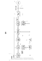
- FIG. It is a figure which shows an example of the functional block of the drive device of the rotary electric machine which concerns on Embodiment 1.
- FIG. It is a figure which shows the schematic structure of the bogie for a railroad vehicle. It is a figure which shows an example of the functional block of the equation of motion of a vehicle for a railroad vehicle and a wheel set. It is a figure which shows the relationship between the slip speed between a wheel and a rail, and a tangential force coefficient. It is a figure which shows the idling gliding at the time of power running and regeneration of a railroad vehicle. It is a figure which shows the phase deviation which occurs during acceleration / deceleration of a railroad vehicle.
- FIG. It is a figure which shows the current vector when the phase deviation occurs between the rotor phase and the phase estimation value of control. It is a figure which shows an example of the functional block of the phase synchronization control part which concerns on Embodiment 1.
- FIG. It is a figure which shows an example of the functional block of the phase deviation convergence part at a constant speed. It is a figure which shows an example of the functional block of the phase deviation convergence part at the time of acceleration / deceleration. It is a figure which shows an example of the effect which added the compensation by the phase deviation convergence part at the time of acceleration / deceleration. It is a figure which shows the method of detecting idling by the output of the phase deviation convergence part at the time of acceleration / deceleration when slipping occurs.
- FIG. 1 It is a figure which shows an example of the functional block of the slipping detection determination unit. It is a figure which shows the comparison between the conventional structure for detecting slipping, and the structure of this invention. It is a figure which shows an example of the functional block of the phase synchronization control part which is the modification of Embodiment 1.
- FIG. It is a figure which shows an example of the functional block of the phase deviation convergence part at a constant speed which is a modification of Embodiment 1.
- FIG. It is a figure which shows an example of the functional block of the phase deviation convergence part at the time of acceleration / deceleration which is the modification of Embodiment 1.
- FIG. 1 It is a figure which shows an example of the functional block of the frequency estimation control part when Embodiment 1 is applied to the drive device of an inducer. It is a figure which shows an example of the functional block of the q-axis current deviation convergence part at a constant speed in a frequency estimation control part. It is a figure which shows an example of the functional block of the q-axis current deviation convergence part at the time of acceleration / deceleration in a frequency estimation control part. It is a figure which shows an example of the functional block of the drive device of the rotary electric machine which concerns on Embodiment 2. FIG. It is a figure which shows an example of the functional block of the slipping slip detection determination unit which concerns on Embodiment 2. FIG.
- FIG. It is a figure which shows an example of the functional block of the drive device of the rotary electric machine which concerns on Embodiment 3.
- FIG. It is a figure which shows an example of the functional block of the idling slip detection determination unit which concerns on Embodiment 3.
- FIG. It is a figure which shows the comparison of the effect by the presence / absence of the upper / lower limit limiter provided in the phase deviation convergence part at the time of acceleration / deceleration.
- FIG. 1 is a diagram showing an example of a functional block of a drive device of a rotary electric machine according to the first embodiment of the present invention.
- a power converter composed of a drive transistor such as an IGBT (Insulated Gate Bipolar Transistor) and a power device such as a diode and a control for the power converter are shown.
- the configuration is shown in a block diagram of the voltage output device 3, and detailed illustration is omitted.
- the rotary electric machine has a configuration in which the synchronous machine 4 is used in FIG. 1, but as shown in FIGS. 18 to 20 described later, an induction machine other than the synchronous machine may be used.
- the voltage output device 3 is based on a switching command from the control device 2 via a drive circuit and a main circuit (not shown, but included in the voltage output device 3).
- a three-phase AC voltage is applied to the synchronous machine 4.
- a drive current flows through the synchronous machine 4 by applying a three-phase AC voltage from the voltage output device 3, and a rotational torque is generated.
- the current detector 5 is composed of a Hall CT (Current Transformer) or the like, and detects waveforms of U-phase, V-phase, and W-phase three-phase currents i u , iv , and i w flowing through the synchronous machine 4, respectively.
- a Hall CT Current Transformer
- the control device 2 is equipped with a control program for driving and controlling the synchronous machine 4 connected as a load.
- a control program for driving and controlling the synchronous machine 4 connected as a load.
- the torque command calculation unit 11 outputs the torque command value ⁇ m * in response to the operation command from the host device.
- the current command calculation unit 10 outputs the current command values id * and i q * of the dq axis for obtaining a predetermined torque with respect to the torque command value ⁇ m * .
- the current detection coordinate conversion unit 8 uses the d-axis estimated phase ⁇ dc recognized by the control device 2 to rotate the three-phase currents i u , iv and i w of the synchronous machine 4 detected by the current detector 5. Is converted into the dq coordinates of, and is output to the current control unit 9 as dq-axis current detection values (i df and i qf ).
- PI Proportional-Integralal
- the voltage command coordinate conversion unit 12 uses the dq-axis voltage command value output by the current control unit 9 and the d-axis estimated phase ⁇ dc to generate three-phase AC voltage command values v u * , v v * , and v w * . Output.
- the PWM control unit 7 gives a PWM voltage (Pulse Width Modulation) switching command to the voltage output device 3 based on the three-phase AC voltage command values v u * , v v * , and v w * output by the voltage command coordinate conversion unit 12. Is output.
- PWM voltage Pulse Width Modulation
- the phase synchronization control unit 14 Based on the phase deviation information ⁇ c , the phase synchronization control unit 14 outputs an angular velocity estimated value ⁇ 1 ⁇ so as to make the phase deviation information ⁇ c zero. At the same time, although the details will be described later, the acceleration / deceleration component phase deviation compensation amount ⁇ is output.
- the phase deviation information ⁇ c indicates the difference between the phase estimated value ⁇ dc and the rotor phase ⁇ d of the synchronous machine 4.
- the phase deviation information ⁇ c is the phase estimated value ⁇ est by sensorless control, or the phase estimated value ⁇ dc using the information of the phase detection value ⁇ r by a resolver or the like, although not shown. Either of the configurations may be used in which the difference between the above is calculated and the phase deviation information ⁇ c is obtained.
- phase deviation estimated value ⁇ est for example, a method of estimating based on a high frequency current detection value when a high frequency voltage is superimposed in a low speed range, or a method of estimating based on a high frequency current detection value in a high speed range, or an induced voltage of a rotating electric machine is used in a high speed range. Use the estimation method.
- the slipping slip detection determination unit 15 determines slipping slip detection based on the acceleration / deceleration phase deviation compensation amount ⁇ output from the phase synchronization control unit 14, and outputs the slip slip detection signal to the torque command calculation unit 11. ..
- the torque command calculation unit 11 receives the slip detection signal, it promptly narrows down the torque command value ⁇ m * to converge the slip generated between the wheels, which are the driving wheels, and the rails, and rail the wheels. Re-adhere to.
- the phase calculation unit 13 integrates the angular velocity estimated value ⁇ 1 ⁇ output from the phase synchronization control unit 14, and outputs the phase estimated value ⁇ dc .
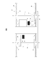
- FIG. 2 is a diagram showing a schematic configuration of a bogie for a railroad vehicle.
- the bogie 31 is equipped with a synchronous machine 4, and the rotor shaft 30 of the synchronous machine 4 transmits power to the small gear 32 via the joint 34.
- the axle 35 is rotated by the reduction gear composed of the small gear 32 and the large gear 33, and the wheels 27 connected to the axle 35 are rotated.
- the wheels 27 accelerate the vehicle by transmitting the force to the bogie 31 by the tangential force generated on the wheels 27 as the reaction force that the wheel tread receives from the rail 36.
- FIG. 3 is a diagram showing a functional block of the equation of motion of the vehicle and one wheel set.
- the equation of motion of the vehicle body and the motor is shown in the block diagram in consideration of the adhesion due to the tangential force coefficient ⁇ between the wheel and the rail, which are the driving wheels, due to the motor torque.
- the force for rotating the wheels is determined by the difference between the wheel torque and the tangential force torque
- the force for accelerating the vehicle is determined by the difference between the tangential force and the running resistance, which change according to the tangential force coefficient ⁇ .
- FIG. 4 is a diagram showing the relationship between the slip speed between the wheel and the rail and the tangential force coefficient ⁇ .
- the tangential force coefficient ⁇ changes according to the slip speed, which is the difference between the wheel peripheral speed and the vehicle body speed. Further, in rainy weather, the tangential force coefficient ⁇ decreases as compared with in fine weather, and slipping is likely to occur. Further, it is known that the tangential force coefficient ⁇ changes not only in rainy weather but also by oil content, fallen leaves and dust on the rail surface, and also by vehicle speed.
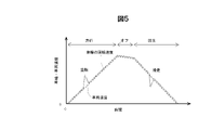
- FIG. 5 is a diagram showing slipping of a railroad vehicle during power running and regeneration.
- the tangential force coefficient ⁇ decreases due to the influence of rain or the like, the force for accelerating the vehicle in FIG. 3 remains small, but only the force for rotating the wheels increases, and the slip speed increases. Then, when the inflection point of the tangential force coefficient ⁇ shown in FIG. 4 is exceeded, idling occurs. Since the tangential force coefficient ⁇ has a negative slope with respect to the slip speed, once slip occurs, the slip will continue to increase in the expanding direction. The above is about power running, but at the time of regeneration, as shown in FIG. 5, gliding occurs in the same manner.
- FIG. 6 is a diagram showing a phase deviation generated during acceleration / deceleration of the vehicle.
- the phase deviation ⁇ is defined by the following equation (Equation 1) as the deviation between the rotor phase ⁇ d of the synchronous machine 4 and the phase estimation value ⁇ dc of the control.
- Equation 1 the phase deviation between the rotor phase ⁇ d of the synchronous machine 4 and the phase estimation value ⁇ dc of the control.
- s is a Laplace operator
- ⁇ r is the rotor angular velocity of the synchronous machine 4.
- the phase synchronization control unit 14 is configured by general PI control
- the proportional gain and the integrated gain in the phase synchronization control unit 14 are K P and KI, respectively
- the angular velocity estimated value ⁇ 1 ⁇ can be calculated by the following equation (Equation 2 ) based on the phase deviation information ⁇ c .
- the rotor angular velocity ⁇ r of the synchronous machine 4 can be calculated by the following equation (Equation 3) from the motor torque ⁇ m and the moment of inertia J.
- P m is the pole logarithm of the synchronous machine 4.
- the moment of inertia J is treated as an equivalent moment of inertia obtained by synthesizing the vehicle mass and the adhesion due to the tangential force coefficient ⁇ when viewed from the motor shaft shown in FIG.
- the moment of inertia J is large, and when slipping occurs between the wheel and rail, it is treated as if the moment of inertia J is small when viewed from the motor shaft.
- Equation 5 Assuming that the phase deviation information ⁇ c recognized by the control device 2 matches the phase deviation ⁇ , the following equation (Equation 5) is obtained.
- phase-locked loop control unit 14 when configured by general PI control, as described using (Equation 1) to (Equation 6), it corresponds to the torque ⁇ m , the moment of inertia J , and the integrated gain KI.
- FIG. 7 is a diagram showing a current vector when a phase deviation ⁇ occurs between the rotor phase ( ⁇ d ) and the control phase estimated value ( ⁇ dc ).
- the reference phase of the rotor of the synchronous machine 4 is set as the d -axis
- the reference phase of the rotor estimated by the control device 2 is set as the dc axis
- the current command values id * and i q * when the phase deviation ⁇ occurs, the current command values id * and i q *.
- the currents that actually flow are id and i q
- the torque ⁇ m actually output by the motor has a large error with respect to the torque command value ⁇ m * .
- a section for compensating for the deviation amount due to the acceleration component is provided in the sensorless control.
- a configuration for detecting slipping without using differential processing will be described using the output value of the term for compensating for the acceleration component.
- FIG. 8 is a diagram showing an example of a functional block of the phase synchronization control unit 14 according to the first embodiment.
- the phase synchronization control unit 14 includes a constant speed phase deviation convergence unit 20 capable of converging the phase deviation to zero at a constant speed, and an acceleration / deceleration phase deviation convergence unit 21 capable of converging the phase deviation during acceleration / deceleration.
- the acceleration / deceleration phase deviation convergence unit 21 inputs the phase deviation amount (before compensation) ⁇ c0 , which is the difference between the phase deviation information ⁇ c and the phase deviation target value, and outputs the acceleration / deceleration component phase deviation compensation amount ⁇ ⁇ . ..
- the constant speed phase deviation convergence unit 20 inputs the phase deviation amount (after compensation) ⁇ c ' , which is the sum of the phase deviation amount (before compensation) ⁇ c0 and the acceleration / deceleration component phase deviation compensation amount ⁇ , and the angular velocity.
- the estimated value ⁇ 1 ⁇ is output.
- FIG. 9 is a diagram showing an example of the functional block of the above-mentioned constant-speed phase deviation convergence unit 20. PI control is performed using the proportional gain K P and the integrated gain KI.
- FIG. 10 is a diagram showing an example of the functional block of the phase deviation converging unit 21 during acceleration / deceleration. Integral gain K II is used for integration.
- the phase synchronization control unit 14 calculates the estimated angular velocity value ⁇ 1 ⁇ from the phase deviation ⁇ c as in the first embodiment.
- the order of the transfer function to be performed may be composed of a quadratic or higher as shown in the following equation (Equation 7).
- Equation 8 Similar to (Equation 5), the following equation (Equation 8) can be obtained by rearranging the equations for the phase deviation ⁇ 'in the first embodiment.
- phase deviation converging unit 21 during acceleration / deceleration operates so that K II / s outputs a compensation amount so that the steady deviation of the phase deviation ⁇ of (Equation 6) becomes zero, so that the output (acceleration / deceleration) is output.
- the fractional phase deviation compensation amount) ⁇ has the relation of the following equation (Equation 10).
- FIG. 11 is a diagram showing an example of the effect of adding compensation by the phase deviation converging unit 21 during acceleration / deceleration.
- the steady deviation of the phase during acceleration / deceleration can be converged to zero by the phase deviation compensation amount ⁇ for the acceleration / deceleration component, which is the output of the phase deviation convergence unit 21 during acceleration / deceleration. Even when slipping occurs and the acceleration / deceleration becomes high, it is possible to prevent the phase deviation from expanding and prevent control instability and deterioration of torque accuracy.
- the acceleration / deceleration component phase deviation compensation amount ⁇ ⁇ which is the output of the acceleration / deceleration phase deviation convergence unit 21, is the vehicle mass and tangential force when viewed from the motor shaft when the torque ⁇ m and the integral gain KI are known. It will change according to the equivalent moment of inertia J including the coefficient ⁇ .
- the inventors can obtain information equivalent to acceleration from the phase deviation information without using differential processing. He found out what he could get and devised a method to detect slipping based on this information.
- FIG. 12 is a diagram showing a method of detecting idling by the output of the phase deviation converging portion during acceleration / deceleration when idling occurs. Since the moment of inertia J seems to have decreased sharply during idling with respect to the phase deviation ⁇ in the normal adhesive state, ⁇ of the output value of the phase deviation converging portion 21 during acceleration / deceleration represented by (Equation 10). ⁇ also increases.
- FIG. 13 is a diagram showing an example of a functional block of the slipping detection determination unit 15.
- the acceleration / deceleration component phase deviation compensation amount ⁇ output by the phase synchronization control unit 14 exceeds the judgment value (slip judgment threshold value or gliding judgment threshold value) of the acceleration component of the phase deviation assumed in the normal adhesive state. It is considered that slipping has occurred, and the slipping detection signal is output to the torque command calculation unit 11.
- the idling determination threshold value or the sliding determination threshold value is set to a degree that is larger than the compensation amount at the time of acceleration / deceleration in the adhesive state and is not erroneously detected according to the vibration component included in the phase deviation information.
- FIG. 14 is a diagram showing a comparison between the conventional configuration for detecting slipping and the configuration of the present invention. The differences in configuration and effect between the prior art and the present invention will be described below with reference to FIG.
- the conventional phase synchronization control unit 16 has a cutoff frequency, the problem that the detection of slipping is delayed is inevitable. Further, when the differential processing is used to calculate the acceleration, it is necessary to provide a low-pass filter processing as in Patent Document 1 and Patent Document 2 as a noise countermeasure, and the detection of slipping is delayed. Is clear.
- the present invention has a configuration in which an acceleration component of the phase deviation estimated value ⁇ est before calculating the frequency estimated value is extracted to detect slipping. Therefore, slipping can be detected earlier than the conventional configuration.
- the sensorless control is performed without causing the torque error due to the phase deviation as described with reference to FIG. It also has the effect of stabilizing and improving torque accuracy.
- FIG. 15 is a diagram showing an example of the functional block of the phase synchronization control unit 14a which is a modification of the first embodiment
- FIG. 16 is an example of the functional block of the constant speed phase deviation convergence unit 20a in the phase synchronization control unit 14a
- FIG. 17 is a diagram showing an example of a functional block of the phase deviation converging unit 21a at the time of acceleration / deceleration in the phase synchronization control unit 14a.
- the phase synchronization control unit 14a has the phase deviation amount (before compensation) ⁇ c0 in parallel with the constant speed phase deviation convergence unit 20a and the acceleration / deceleration phase deviation convergence unit 21a. Entered.
- the phase deviation converging unit 21a at the time of acceleration / deceleration calculates the angular velocity estimated value ⁇ 1 ⁇ from the phase deviation ⁇ c by providing the squared term of 1 / s as shown in FIG.
- the order of the denominator of the transfer function is quadratic. This has the effect of suppressing the phase deviation ⁇ during acceleration / deceleration.
- the order of the denominator of the transfer function is quadratic or higher, the order may be any order as long as the terms of the quadratic or higher are included, and the phase-locked loop control unit 14 starts from FIG.
- the configuration is not necessarily limited to the configuration shown in FIG. 10 or FIGS. 15 to 17.
- phase synchronization control unit 14 is configured as the phase deviation information ⁇ c by calculating the difference from the phase estimated value ⁇ dc using the information of the phase detection value ⁇ r by the resolver or the like, the acceleration / deceleration of the vehicle is in progress. Similarly, since the steady phase deviation remains, it can be applied even in the configuration of the control with a resolver or the control with a speed sensor.
- the synchronous machine 4 has been described as an example of the rotary electric machine, but the present invention is not limited to the synchronous machine, and can be applied to other rotary electric machines such as an induction machine.
- FIG. 18 is a diagram showing an example of a functional block of the frequency estimation control unit 40 when the first embodiment is applied to the drive device of the induction machine
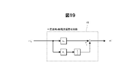
- FIG. 19 is a diagram showing a constant speed q-axis current deviation in the frequency estimation control unit 40.
- FIG. 20 is a diagram showing an example of a functional block of the convergence unit 41
- FIG. 20 is a diagram showing an example of a functional block of the q-axis current deviation convergence unit 42 during acceleration / deceleration in the frequency estimation control unit 40.
- the q-axis current deviation due to acceleration is used as the q-axis current deviation converging unit 42 during acceleration / deceleration.
- the configuration is such that the amount is compensated. That is, if the configuration is such that slipping is detected based on the acceleration / deceleration component q-axis current deviation compensation amount ⁇ i q_ ⁇ , which is the output of the q-axis current deviation converging unit 42 during acceleration / deceleration, slipping is performed while stabilizing the speed estimation control. Can be obtained at an early stage.
- the state quantity used for inputting the calculation of the estimated angular velocity value during acceleration / deceleration of the rotary electric machine (in the case of a synchronous machine, the estimated phase of the rotor, in the case of an inducer, the inducer is used.
- the present invention is configured to output a compensation value for correcting the state amount in order to suppress the deviation amount generated in the flowing current) to substantially zero, and to detect slipping when the compensation value exceeds a predetermined value. The effect of can be obtained.
- the drive device of the rotary electric machine is a voltage output device 3 that outputs a voltage to the synchronous machine 4, and a control that controls the output voltage of the voltage output device 3 based on the torque command value ⁇ m * .
- the control device 2 includes a device 2 and a phase synchronization control unit 14 that outputs an angular velocity estimated value ⁇ 1 ⁇ from the phase deviation information of the rotor.
- the phase synchronization control unit 14 has an acceleration / deceleration phase deviation convergence unit 21 that suppresses a steady deviation of the estimated phase during acceleration / deceleration, and is driven by the synchronous machine 4 based on the output of the acceleration / deceleration phase deviation convergence unit 21.
- the slipping slip detection determination unit 15 for detecting the slipping state of the wheels to be slid is provided. This makes it possible to realize high-speed idling slip detection while stabilizing the control system even during slipping. Further, in the case of the inducer, the same effect can be obtained by replacing the phase deviation with the q-axis current deviation.
- the second embodiment according to the present invention is different from the first embodiment in that the determination threshold value for detecting idling slip by the idling slip detection determination unit 15 is made variable according to the operating state of the vehicle and the surrounding environment. ..
- an appropriate slipping determination threshold value can be set, and slipping is performed more than in the first embodiment. While preventing erroneous detection, it is possible to further speed up the detection of slipping.
- FIG. 21 is a diagram showing an example of a functional block of the drive device of the rotary electric machine according to the second embodiment.
- the torque command value ⁇ m * the occupancy rate information, the weather information, the position information in the formation, and the angular velocity estimated value ⁇ 1 ⁇ are input to the slip slip detection determination unit 15 to make the slip slip determination threshold variable. ..
- FIG. 22 is a diagram showing an example of a functional block of the slipping detection determination unit 15 according to the second embodiment.
- the value obtained by dividing the torque command value ⁇ m * by the integrated gain KI and the moment of inertia J is defined as the slip slip determination threshold value according to the calculation formula (Equation 10).
- the occupancy rate information is calculated by the equivalent moment of inertia calculation unit 50 into the equivalent moment of inertia J.
- the weather information correction gain calculation unit 51 that inputs the weather information calculates the weather information correction gain and outputs it as one of the correction gains of the slip slip determination threshold value.
- the axle 35 to which the rotary electric machine is connected is connected to the traveling direction in the same manner as the principle that the tangential force coefficient ⁇ changes according to the weather, that is, the condition of the road surface (rail surface).
- the weather that is, the condition of the road surface (rail surface).
- the axle 35 to which the rotary electric machine is connected is located on the rear side with respect to the traveling direction, slipping tends to be relatively unlikely to occur even in rainy weather or the like.
- the traveling direction of the formation itself and the car number on which the axle 35 to which the rotary electric machine is connected can be discriminated, it is possible to adjust to an appropriate idling gliding determination threshold. For example, if it is located on the side of the first car in the direction of travel, it will be easier to slip, so the judgment threshold will be lowered, and if it is located on the side of the car behind in the direction of travel, it will be difficult to slip. Increase the judgment threshold. By doing so, it is possible to set an appropriate determination threshold value according to the position of the vehicle having the axle in the formation, and it is possible to realize higher speed detection while preventing false detection of slipping.
- the in-organization position information correction gain calculation unit 52 that inputs the in-organization position information calculates the in-organization position information correction gain and outputs it as one of the correction gains of the slip slip determination threshold value.
- the tangential force coefficient ⁇ has a dependence on the vehicle speed (see the tangential force coefficient table shown in FIG. 3), and as the vehicle speed increases, the tangential force coefficient ⁇ increases. It becomes smaller.
- the running resistance also increases as the speed increases, and the wheels are more likely to slip. Therefore, for example, when the angular velocity estimated value ⁇ 1 ⁇ becomes high, it becomes easy to slip and slide, so the judgment threshold value is lowered, and when the angular velocity estimated value ⁇ 1 ⁇ becomes low, it becomes difficult to slip. Increase the judgment threshold.
- the frequency of the rotary electric machine or the vehicle speed may be directly used. By doing so, it is possible to set an appropriate determination threshold value according to the vehicle speed, and it is possible to realize higher speed detection while preventing false detection of slipping.
- the speed correction gain calculation unit 53 that inputs the angular velocity estimated value ⁇ 1 ⁇ calculates the running resistance correction gain and outputs it as one of the correction gains of the slip slip determination threshold value.
- the means for adjusting these determination threshold values may be any method as long as the idling / sliding determination threshold value is changed according to each parameter, such as an arithmetic expression or a table for each parameter.
- the value obtained by reversing the sign is used as the determination threshold value, but a correction gain calculation may be provided individually for idling and gliding.
- the torque command value ⁇ m * , the occupancy rate information, the weather information, the position information in the formation, and the angular velocity estimated value ⁇ 1 ⁇ are taken into the slipping slip detection determination unit 15, and the values are responsive to these information. Therefore, the determination threshold value for detecting slipping is made variable. As a result, it is possible to further increase the speed of idling gliding detection while preventing false detection of idling gliding. [Embodiment 3]
- the third embodiment according to the present invention is different from the second embodiment in that an upper / lower limit limiter is provided for the output of the phase deviation converging unit 21 during acceleration / deceleration.
- FIG. 23 is a diagram showing an example of a functional block of the drive device of the rotary electric machine according to the third embodiment.
- the slip slip determination threshold value is output from the slip slip detection determination unit 15 and input to the phase synchronization control 14, and the upper and lower limit values are calculated with respect to the output of the phase deviation convergence unit 21 during acceleration / deceleration. Used for.
- FIG. 24 is a diagram showing an example of a functional block of the slipping detection determination unit 15 according to the third embodiment. A function of outputting a determination threshold value for detecting idling slip has been added to the idling slip detection determination unit 15 according to the second embodiment shown in FIG. 22.
- FIG. 25 is a diagram showing an example of a functional block of the phase deviation converging unit 21 during acceleration / deceleration according to the third embodiment.
- the upper and lower limit limiters 22 are provided for the output of the acceleration / deceleration component phase deviation compensation amount ⁇ .
- the set value of the upper and lower limit limiters 22 is set so as to be slightly larger than the level at which the slip detection is determined by multiplying the slip slip determination threshold by the determination threshold adjustment gain.
- the upper limit value of the upper and lower limit limiter 22 is set based on the judgment threshold value at the time of idling, and the lower limit value of the upper / lower limit limiter 22 is set based on the judgment threshold value at the time of sliding.
- FIG. 26 is a diagram showing a comparison of the effects depending on the presence / absence of the upper / lower limit limiter 22 provided in the phase deviation converging portion 21 during acceleration / deceleration.
- phase deviation compensation amount ⁇ for acceleration / deceleration will continue to accumulate until the idling is converged after the idling is detected and the torque is narrowed down. Therefore, even after re-adhesion, it takes time for the acceleration / deceleration phase deviation compensation amount ⁇ to return to the steady value.
- the acceleration / deceleration component phase deviation compensation amount ⁇ is prevented from exceeding, and the acceleration / deceleration after re-adhesion is prevented. It is possible to obtain the effect of accelerating the convergence of the fractional phase deviation compensation amount ⁇ to the steady value.
- the ON time of the idling slip detection timing becomes closer to the actual idling time, which has the effect of being optimized, and there is also a risk of falsely detecting idling slip after re-adhesion. Can be reduced.
- the third embodiment by providing the upper and lower limit limiters 22 at the output of the phase deviation converging unit 21 during acceleration / deceleration, a steady value of the acceleration / deceleration component phase deviation compensation amount ⁇ is provided after re-adhesion control by torque operation. It accelerates the convergence to. This makes it possible to prevent erroneous detection of slipping after re-adhesion.
- Carriage 32 ... Small gears, 33 ... Large gear, 34 ... Joint, 35 ... Axle, 36 ... Rail, 40 ... Frequency estimation control unit, 41 ... Q-axis current deviation convergence unit at constant speed, 42 ... Q-axis current deviation convergence unit during acceleration / deceleration, 50 ... Equivalent inertia moment calculation unit, 51 ... Weather information correction gain calculation unit, 52 ... In-organization position information correction gain calculation unit, 53 ... Speed correction gain calculation unit
Landscapes
- Engineering & Computer Science (AREA)
- Power Engineering (AREA)
- Transportation (AREA)
- Mechanical Engineering (AREA)
- Electric Propulsion And Braking For Vehicles (AREA)
- Control Of Ac Motors In General (AREA)
Priority Applications (3)
| Application Number | Priority Date | Filing Date | Title |
|---|---|---|---|
| JP2022566924A JPWO2022118822A1 (zh) | 2020-12-04 | 2021-11-30 | |
| CN202180081292.4A CN116547164A (zh) | 2020-12-04 | 2021-11-30 | 旋转电机的驱动装置、驱动方法以及铁道车辆 |
| EP21900575.8A EP4258540A1 (en) | 2020-12-04 | 2021-11-30 | Drive device and drive method for rotary electric machine, and railway vehicle |
Applications Claiming Priority (2)
| Application Number | Priority Date | Filing Date | Title |
|---|---|---|---|
| JP2020201959 | 2020-12-04 | ||
| JP2020-201959 | 2020-12-04 |
Publications (1)
| Publication Number | Publication Date |
|---|---|
| WO2022118822A1 true WO2022118822A1 (ja) | 2022-06-09 |
Family
ID=81853196
Family Applications (1)
| Application Number | Title | Priority Date | Filing Date |
|---|---|---|---|
| PCT/JP2021/043765 WO2022118822A1 (ja) | 2020-12-04 | 2021-11-30 | 回転電機の駆動装置、駆動方法および鉄道車両 |
Country Status (4)
| Country | Link |
|---|---|
| EP (1) | EP4258540A1 (zh) |
| JP (1) | JPWO2022118822A1 (zh) |
| CN (1) | CN116547164A (zh) |
| WO (1) | WO2022118822A1 (zh) |
Citations (2)
| Publication number | Priority date | Publication date | Assignee | Title |
|---|---|---|---|---|
| JP2011193568A (ja) * | 2010-03-12 | 2011-09-29 | Fuji Electric Co Ltd | 電気車制御装置 |
| JP2012120320A (ja) * | 2010-11-30 | 2012-06-21 | Toshiba Corp | 回転センサレス制御装置 |
-
2021
- 2021-11-30 CN CN202180081292.4A patent/CN116547164A/zh active Pending
- 2021-11-30 WO PCT/JP2021/043765 patent/WO2022118822A1/ja active Application Filing
- 2021-11-30 JP JP2022566924A patent/JPWO2022118822A1/ja active Pending
- 2021-11-30 EP EP21900575.8A patent/EP4258540A1/en active Pending
Patent Citations (2)
| Publication number | Priority date | Publication date | Assignee | Title |
|---|---|---|---|---|
| JP2011193568A (ja) * | 2010-03-12 | 2011-09-29 | Fuji Electric Co Ltd | 電気車制御装置 |
| JP2012120320A (ja) * | 2010-11-30 | 2012-06-21 | Toshiba Corp | 回転センサレス制御装置 |
Also Published As
| Publication number | Publication date |
|---|---|
| JPWO2022118822A1 (zh) | 2022-06-09 |
| CN116547164A (zh) | 2023-08-04 |
| EP4258540A1 (en) | 2023-10-11 |
Similar Documents
| Publication | Publication Date | Title |
|---|---|---|
| JP4770538B2 (ja) | 電気駆動車両、及び電気駆動車両の制御方法 | |
| JP4573835B2 (ja) | 電気車制御装置 | |
| US5677610A (en) | Control apparatus for electric vehicles | |
| WO2006033181A1 (ja) | 誘導電動機のベクトル制御装置 | |
| EP2599688A1 (en) | Electric power steering device | |
| KR20120048715A (ko) | 전기차의 제어 장치 | |
| JP6540716B2 (ja) | 車両の制御装置および車両の制御方法 | |
| JP2008086085A (ja) | 電気車制御装置 | |
| JP5994705B2 (ja) | 各輪独立駆動台車の各輪モータ制御装置 | |
| JP4850870B2 (ja) | 電気車制御方法及び電気車制御装置 | |
| JP5643271B2 (ja) | 空転滑走発生検出方法及び電動機制御装置 | |
| WO2022118822A1 (ja) | 回転電機の駆動装置、駆動方法および鉄道車両 | |
| JP3933983B2 (ja) | 電気車制御装置 | |
| JP4903740B2 (ja) | 電動機制御方法及び電動機制御装置 | |
| JP2002095299A (ja) | 電車の駆動制御装置 | |
| JP6064727B2 (ja) | 各輪独立駆動台車の制御装置 | |
| JP5195889B2 (ja) | 電気駆動車両 | |
| JP4131785B2 (ja) | 電気車の駆動制御装置及び空転制御方法 | |
| JP4818244B2 (ja) | 電動機制御装置及び再粘着制御方法 | |
| WO2024029310A1 (ja) | 車両制御装置、車両制御方法および車両制御システム | |
| JP7105608B2 (ja) | 電動機制御方法及び電動機制御装置 | |
| JP5344195B2 (ja) | 電気駆動車両 | |
| JP2000253506A (ja) | 速度センサレス制御を用いた電気車制御装置 | |
| JP4342878B2 (ja) | 電気車制御装置 | |
| JPWO2022118822A5 (zh) |
Legal Events
| Date | Code | Title | Description |
|---|---|---|---|
| 121 | Ep: the epo has been informed by wipo that ep was designated in this application |
Ref document number: 21900575 Country of ref document: EP Kind code of ref document: A1 |
|
| ENP | Entry into the national phase |
Ref document number: 2022566924 Country of ref document: JP Kind code of ref document: A |
|
| WWE | Wipo information: entry into national phase |
Ref document number: 202180081292.4 Country of ref document: CN |
|
| NENP | Non-entry into the national phase |
Ref country code: DE |
|
| ENP | Entry into the national phase |
Ref document number: 2021900575 Country of ref document: EP Effective date: 20230704 |