WO2022118822A1 - 回転電機の駆動装置、駆動方法および鉄道車両 - Google Patents
回転電機の駆動装置、駆動方法および鉄道車両 Download PDFInfo
- Publication number
- WO2022118822A1 WO2022118822A1 PCT/JP2021/043765 JP2021043765W WO2022118822A1 WO 2022118822 A1 WO2022118822 A1 WO 2022118822A1 JP 2021043765 W JP2021043765 W JP 2021043765W WO 2022118822 A1 WO2022118822 A1 WO 2022118822A1
- Authority
- WO
- WIPO (PCT)
- Prior art keywords
- electric machine
- rotary electric
- value
- phase
- deviation
- Prior art date
Links
- 238000000034 method Methods 0.000 title claims description 40
- 230000001133 acceleration Effects 0.000 claims description 103
- 238000001514 detection method Methods 0.000 claims description 62
- 230000001360 synchronised effect Effects 0.000 claims description 28
- 230000006698 induction Effects 0.000 claims description 13
- 230000015572 biosynthetic process Effects 0.000 claims description 7
- 230000007423 decrease Effects 0.000 claims description 6
- 230000000087 stabilizing effect Effects 0.000 abstract description 11
- 238000010586 diagram Methods 0.000 description 28
- 230000000694 effects Effects 0.000 description 18
- 238000012545 processing Methods 0.000 description 14
- 238000012937 correction Methods 0.000 description 13
- 239000000853 adhesive Substances 0.000 description 8
- 230000001070 adhesive effect Effects 0.000 description 8
- 238000006243 chemical reaction Methods 0.000 description 8
- 230000008859 change Effects 0.000 description 6
- 230000004048 modification Effects 0.000 description 6
- 238000012986 modification Methods 0.000 description 6
- 230000003111 delayed effect Effects 0.000 description 4
- 239000000411 inducer Substances 0.000 description 4
- 230000008929 regeneration Effects 0.000 description 3
- 238000011069 regeneration method Methods 0.000 description 3
- 238000012546 transfer Methods 0.000 description 3
- 238000007796 conventional method Methods 0.000 description 2
- 230000002542 deteriorative effect Effects 0.000 description 2
- 230000004069 differentiation Effects 0.000 description 2
- 239000000428 dust Substances 0.000 description 2
- 230000010354 integration Effects 0.000 description 2
- 230000010363 phase shift Effects 0.000 description 2
- 230000008569 process Effects 0.000 description 2
- 230000009467 reduction Effects 0.000 description 2
- 230000003247 decreasing effect Effects 0.000 description 1
- 230000001687 destabilization Effects 0.000 description 1
- 230000006866 deterioration Effects 0.000 description 1
- 238000009499 grossing Methods 0.000 description 1
- 230000006872 improvement Effects 0.000 description 1
- 238000009940 knitting Methods 0.000 description 1
- 230000002093 peripheral effect Effects 0.000 description 1
- 230000004044 response Effects 0.000 description 1
- 230000002194 synthesizing effect Effects 0.000 description 1
- 230000001052 transient effect Effects 0.000 description 1
Images


Classifications
-
- B—PERFORMING OPERATIONS; TRANSPORTING
- B60—VEHICLES IN GENERAL
- B60L—PROPULSION OF ELECTRICALLY-PROPELLED VEHICLES; SUPPLYING ELECTRIC POWER FOR AUXILIARY EQUIPMENT OF ELECTRICALLY-PROPELLED VEHICLES; ELECTRODYNAMIC BRAKE SYSTEMS FOR VEHICLES IN GENERAL; MAGNETIC SUSPENSION OR LEVITATION FOR VEHICLES; MONITORING OPERATING VARIABLES OF ELECTRICALLY-PROPELLED VEHICLES; ELECTRIC SAFETY DEVICES FOR ELECTRICALLY-PROPELLED VEHICLES
- B60L15/00—Methods, circuits, or devices for controlling the traction-motor speed of electrically-propelled vehicles
- B60L15/02—Methods, circuits, or devices for controlling the traction-motor speed of electrically-propelled vehicles characterised by the form of the current used in the control circuit
- B60L15/025—Methods, circuits, or devices for controlling the traction-motor speed of electrically-propelled vehicles characterised by the form of the current used in the control circuit using field orientation; Vector control; Direct Torque Control [DTC]
-
- H—ELECTRICITY
- H02—GENERATION; CONVERSION OR DISTRIBUTION OF ELECTRIC POWER
- H02P—CONTROL OR REGULATION OF ELECTRIC MOTORS, ELECTRIC GENERATORS OR DYNAMO-ELECTRIC CONVERTERS; CONTROLLING TRANSFORMERS, REACTORS OR CHOKE COILS
- H02P21/00—Arrangements or methods for the control of electric machines by vector control, e.g. by control of field orientation
- H02P21/14—Estimation or adaptation of machine parameters, e.g. flux, current or voltage
- H02P21/18—Estimation of position or speed
-
- B—PERFORMING OPERATIONS; TRANSPORTING
- B60—VEHICLES IN GENERAL
- B60L—PROPULSION OF ELECTRICALLY-PROPELLED VEHICLES; SUPPLYING ELECTRIC POWER FOR AUXILIARY EQUIPMENT OF ELECTRICALLY-PROPELLED VEHICLES; ELECTRODYNAMIC BRAKE SYSTEMS FOR VEHICLES IN GENERAL; MAGNETIC SUSPENSION OR LEVITATION FOR VEHICLES; MONITORING OPERATING VARIABLES OF ELECTRICALLY-PROPELLED VEHICLES; ELECTRIC SAFETY DEVICES FOR ELECTRICALLY-PROPELLED VEHICLES
- B60L2200/00—Type of vehicles
- B60L2200/26—Rail vehicles
-
- B—PERFORMING OPERATIONS; TRANSPORTING
- B60—VEHICLES IN GENERAL
- B60L—PROPULSION OF ELECTRICALLY-PROPELLED VEHICLES; SUPPLYING ELECTRIC POWER FOR AUXILIARY EQUIPMENT OF ELECTRICALLY-PROPELLED VEHICLES; ELECTRODYNAMIC BRAKE SYSTEMS FOR VEHICLES IN GENERAL; MAGNETIC SUSPENSION OR LEVITATION FOR VEHICLES; MONITORING OPERATING VARIABLES OF ELECTRICALLY-PROPELLED VEHICLES; ELECTRIC SAFETY DEVICES FOR ELECTRICALLY-PROPELLED VEHICLES
- B60L2220/00—Electrical machine types; Structures or applications thereof
- B60L2220/10—Electrical machine types
- B60L2220/12—Induction machines
-
- B—PERFORMING OPERATIONS; TRANSPORTING
- B60—VEHICLES IN GENERAL
- B60L—PROPULSION OF ELECTRICALLY-PROPELLED VEHICLES; SUPPLYING ELECTRIC POWER FOR AUXILIARY EQUIPMENT OF ELECTRICALLY-PROPELLED VEHICLES; ELECTRODYNAMIC BRAKE SYSTEMS FOR VEHICLES IN GENERAL; MAGNETIC SUSPENSION OR LEVITATION FOR VEHICLES; MONITORING OPERATING VARIABLES OF ELECTRICALLY-PROPELLED VEHICLES; ELECTRIC SAFETY DEVICES FOR ELECTRICALLY-PROPELLED VEHICLES
- B60L2220/00—Electrical machine types; Structures or applications thereof
- B60L2220/10—Electrical machine types
- B60L2220/14—Synchronous machines
-
- B—PERFORMING OPERATIONS; TRANSPORTING
- B60—VEHICLES IN GENERAL
- B60L—PROPULSION OF ELECTRICALLY-PROPELLED VEHICLES; SUPPLYING ELECTRIC POWER FOR AUXILIARY EQUIPMENT OF ELECTRICALLY-PROPELLED VEHICLES; ELECTRODYNAMIC BRAKE SYSTEMS FOR VEHICLES IN GENERAL; MAGNETIC SUSPENSION OR LEVITATION FOR VEHICLES; MONITORING OPERATING VARIABLES OF ELECTRICALLY-PROPELLED VEHICLES; ELECTRIC SAFETY DEVICES FOR ELECTRICALLY-PROPELLED VEHICLES
- B60L2240/00—Control parameters of input or output; Target parameters
- B60L2240/10—Vehicle control parameters
- B60L2240/12—Speed
-
- B—PERFORMING OPERATIONS; TRANSPORTING
- B60—VEHICLES IN GENERAL
- B60L—PROPULSION OF ELECTRICALLY-PROPELLED VEHICLES; SUPPLYING ELECTRIC POWER FOR AUXILIARY EQUIPMENT OF ELECTRICALLY-PROPELLED VEHICLES; ELECTRODYNAMIC BRAKE SYSTEMS FOR VEHICLES IN GENERAL; MAGNETIC SUSPENSION OR LEVITATION FOR VEHICLES; MONITORING OPERATING VARIABLES OF ELECTRICALLY-PROPELLED VEHICLES; ELECTRIC SAFETY DEVICES FOR ELECTRICALLY-PROPELLED VEHICLES
- B60L2240/00—Control parameters of input or output; Target parameters
- B60L2240/40—Drive Train control parameters
- B60L2240/42—Drive Train control parameters related to electric machines
- B60L2240/421—Speed
-
- B—PERFORMING OPERATIONS; TRANSPORTING
- B60—VEHICLES IN GENERAL
- B60L—PROPULSION OF ELECTRICALLY-PROPELLED VEHICLES; SUPPLYING ELECTRIC POWER FOR AUXILIARY EQUIPMENT OF ELECTRICALLY-PROPELLED VEHICLES; ELECTRODYNAMIC BRAKE SYSTEMS FOR VEHICLES IN GENERAL; MAGNETIC SUSPENSION OR LEVITATION FOR VEHICLES; MONITORING OPERATING VARIABLES OF ELECTRICALLY-PROPELLED VEHICLES; ELECTRIC SAFETY DEVICES FOR ELECTRICALLY-PROPELLED VEHICLES
- B60L2240/00—Control parameters of input or output; Target parameters
- B60L2240/40—Drive Train control parameters
- B60L2240/42—Drive Train control parameters related to electric machines
- B60L2240/423—Torque
-
- B—PERFORMING OPERATIONS; TRANSPORTING
- B60—VEHICLES IN GENERAL
- B60L—PROPULSION OF ELECTRICALLY-PROPELLED VEHICLES; SUPPLYING ELECTRIC POWER FOR AUXILIARY EQUIPMENT OF ELECTRICALLY-PROPELLED VEHICLES; ELECTRODYNAMIC BRAKE SYSTEMS FOR VEHICLES IN GENERAL; MAGNETIC SUSPENSION OR LEVITATION FOR VEHICLES; MONITORING OPERATING VARIABLES OF ELECTRICALLY-PROPELLED VEHICLES; ELECTRIC SAFETY DEVICES FOR ELECTRICALLY-PROPELLED VEHICLES
- B60L2240/00—Control parameters of input or output; Target parameters
- B60L2240/40—Drive Train control parameters
- B60L2240/42—Drive Train control parameters related to electric machines
- B60L2240/427—Voltage
-
- B—PERFORMING OPERATIONS; TRANSPORTING
- B60—VEHICLES IN GENERAL
- B60L—PROPULSION OF ELECTRICALLY-PROPELLED VEHICLES; SUPPLYING ELECTRIC POWER FOR AUXILIARY EQUIPMENT OF ELECTRICALLY-PROPELLED VEHICLES; ELECTRODYNAMIC BRAKE SYSTEMS FOR VEHICLES IN GENERAL; MAGNETIC SUSPENSION OR LEVITATION FOR VEHICLES; MONITORING OPERATING VARIABLES OF ELECTRICALLY-PROPELLED VEHICLES; ELECTRIC SAFETY DEVICES FOR ELECTRICALLY-PROPELLED VEHICLES
- B60L2240/00—Control parameters of input or output; Target parameters
- B60L2240/40—Drive Train control parameters
- B60L2240/42—Drive Train control parameters related to electric machines
- B60L2240/429—Current
-
- B—PERFORMING OPERATIONS; TRANSPORTING
- B60—VEHICLES IN GENERAL
- B60L—PROPULSION OF ELECTRICALLY-PROPELLED VEHICLES; SUPPLYING ELECTRIC POWER FOR AUXILIARY EQUIPMENT OF ELECTRICALLY-PROPELLED VEHICLES; ELECTRODYNAMIC BRAKE SYSTEMS FOR VEHICLES IN GENERAL; MAGNETIC SUSPENSION OR LEVITATION FOR VEHICLES; MONITORING OPERATING VARIABLES OF ELECTRICALLY-PROPELLED VEHICLES; ELECTRIC SAFETY DEVICES FOR ELECTRICALLY-PROPELLED VEHICLES
- B60L2240/00—Control parameters of input or output; Target parameters
- B60L2240/40—Drive Train control parameters
- B60L2240/52—Drive Train control parameters related to converters
- B60L2240/526—Operating parameters
-
- B—PERFORMING OPERATIONS; TRANSPORTING
- B60—VEHICLES IN GENERAL
- B60L—PROPULSION OF ELECTRICALLY-PROPELLED VEHICLES; SUPPLYING ELECTRIC POWER FOR AUXILIARY EQUIPMENT OF ELECTRICALLY-PROPELLED VEHICLES; ELECTRODYNAMIC BRAKE SYSTEMS FOR VEHICLES IN GENERAL; MAGNETIC SUSPENSION OR LEVITATION FOR VEHICLES; MONITORING OPERATING VARIABLES OF ELECTRICALLY-PROPELLED VEHICLES; ELECTRIC SAFETY DEVICES FOR ELECTRICALLY-PROPELLED VEHICLES
- B60L2240/00—Control parameters of input or output; Target parameters
- B60L2240/40—Drive Train control parameters
- B60L2240/52—Drive Train control parameters related to converters
- B60L2240/529—Current
-
- Y—GENERAL TAGGING OF NEW TECHNOLOGICAL DEVELOPMENTS; GENERAL TAGGING OF CROSS-SECTIONAL TECHNOLOGIES SPANNING OVER SEVERAL SECTIONS OF THE IPC; TECHNICAL SUBJECTS COVERED BY FORMER USPC CROSS-REFERENCE ART COLLECTIONS [XRACs] AND DIGESTS
- Y02—TECHNOLOGIES OR APPLICATIONS FOR MITIGATION OR ADAPTATION AGAINST CLIMATE CHANGE
- Y02T—CLIMATE CHANGE MITIGATION TECHNOLOGIES RELATED TO TRANSPORTATION
- Y02T10/00—Road transport of goods or passengers
- Y02T10/60—Other road transportation technologies with climate change mitigation effect
- Y02T10/72—Electric energy management in electromobility
Definitions
- the present invention relates to a drive device, a drive method, and a railroad vehicle equipped with the rotary electric machine.
- wheels which are driving wheels, are rotated by the torque of a rotary electric machine, and the vehicle is accelerated by the tangential force generated in the wheels as a reaction force received from the rail by the wheel tread.
- This tangential force varies depending on the tangential force coefficient ⁇ that represents the adhesive state between the wheel and the rail, and when the wheel torque becomes excessive than the tangential force, the force that accelerates the vehicle remains small and the wheel is rotated. Only becomes larger, resulting in wheel slipping or slipping (hereinafter abbreviated as "sliding").
- sliding wheel slipping or slipping
- idling re-adhesion control is widely used in which the wheel is re-adhered to the rail by promptly detecting the idling slip that occurs between the wheel and the rail and narrowing down the torque of the rotary electric machine.
- control is performed in order to enable detection of idling or sliding of the drive shaft of the induction motor even when the relative speed of each induction motor is small without using a speed sensor.
- a technique is disclosed in which an acceleration estimated value ⁇ i is calculated from a time change (differential value) of a frequency command value of an apparatus, and when it is determined that a predetermined threshold value is exceeded, it is determined that slipping has occurred.
- Patent Document 2 it is proportional to the position error estimation value of the permanent magnet synchronous motor in order to reduce the delay of acceleration estimation due to the ⁇ , ⁇ -axis current and the vibration of the mechanical system, and the delay of idling gliding control.
- a technique for calculating an acceleration estimated value by adding a term and a differential value of a term proportional to the position error estimated value is disclosed.
- Patent Document 3 describes two points that the control becomes unstable due to the control gain being too large in the steady state against a sudden change in speed such as when idling, and the withstand of step-out is improved in the transient.
- a technique for making the sensorless control gain variable according to the rotation phase angle error is disclosed.
- Patent Document 1 calculates an acceleration estimated value ⁇ i from a time change (differential value) of a frequency command value of a control device that drives a plurality of induction motors in parallel without a speed sensor.
- the calculated output frequency is subjected to a low-pass filter (LPF) calculation with a passing region of 3 Hz or less, and then the first floor is performed.
- LPF low-pass filter
- Patent Document 2 proposes a method of differentiating the position error estimated value of the permanent magnet synchronous motor to calculate the acceleration estimated value and reducing the detection delay of slipping.
- This method has a configuration in which the acceleration is calculated from the differential processing in the same manner as the method of calculating the acceleration estimated value from the differential value of the frequency which is generally often used, and is a process for smoothing the vibration of the differential value (low-pass filter). Filter etc.) is required. Therefore, as described in paragraphs [0028] to [0031] of Patent Document 2, a low-pass filter having time constants Ta and Tb is configured as the vibration reduction countermeasure units 54 and 55, and therefore, due to the influence of this low-pass filter. There is a problem that the delay in the detection of slipping cannot be sufficiently improved.
- Patent Document 3 proposes a method in which the sensorless control gain is greatly changed as the estimated absolute value of the phase shift becomes larger in order to stabilize the sensorless control when the speed suddenly changes.
- the sensorless control gain is greatly changed as the estimated absolute value of the phase shift becomes larger in order to stabilize the sensorless control when the speed suddenly changes.
- it is desirable to have a control system that can stably follow the position sensorless control even when the speed changes due to high acceleration such as when idling.
- the present invention has been made in consideration of the above points, and a term for compensating the deviation amount due to the acceleration component is provided in the speed estimation value of the sensorless control so that the sensorless control does not become unstable during idling and sliding. Furthermore, by detecting slipping based on the magnitude of this compensation amount without using differential processing, the purpose is to provide a technique that realizes high-speed slipping detection while stabilizing the control system. do.
- one of the typical drive devices of the rotary electric machine is a voltage output device that outputs the drive voltage to the rotary electric machine and a current detector that detects the current flowing through the rotary electric machine.
- a control device that estimates and calculates the angular speed of the rotor of the rotary electric machine, and the control device suppresses the steady deviation that occurs in the state quantity that is the input for estimating and calculating the angular speed during acceleration and deceleration of the rotary electric machine to almost zero.
- a compensation value for correcting the state amount is calculated, and when the compensation value exceeds a predetermined value, idling or sliding of the drive wheel driven by the rotary electric machine is detected.
- FIG. It is a figure which shows an example of the functional block of the drive device of the rotary electric machine which concerns on Embodiment 1.
- FIG. It is a figure which shows the schematic structure of the bogie for a railroad vehicle. It is a figure which shows an example of the functional block of the equation of motion of a vehicle for a railroad vehicle and a wheel set. It is a figure which shows the relationship between the slip speed between a wheel and a rail, and a tangential force coefficient. It is a figure which shows the idling gliding at the time of power running and regeneration of a railroad vehicle. It is a figure which shows the phase deviation which occurs during acceleration / deceleration of a railroad vehicle.
- FIG. It is a figure which shows the current vector when the phase deviation occurs between the rotor phase and the phase estimation value of control. It is a figure which shows an example of the functional block of the phase synchronization control part which concerns on Embodiment 1.
- FIG. It is a figure which shows an example of the functional block of the phase deviation convergence part at a constant speed. It is a figure which shows an example of the functional block of the phase deviation convergence part at the time of acceleration / deceleration. It is a figure which shows an example of the effect which added the compensation by the phase deviation convergence part at the time of acceleration / deceleration. It is a figure which shows the method of detecting idling by the output of the phase deviation convergence part at the time of acceleration / deceleration when slipping occurs.
- FIG. 1 It is a figure which shows an example of the functional block of the slipping detection determination unit. It is a figure which shows the comparison between the conventional structure for detecting slipping, and the structure of this invention. It is a figure which shows an example of the functional block of the phase synchronization control part which is the modification of Embodiment 1.
- FIG. It is a figure which shows an example of the functional block of the phase deviation convergence part at a constant speed which is a modification of Embodiment 1.
- FIG. It is a figure which shows an example of the functional block of the phase deviation convergence part at the time of acceleration / deceleration which is the modification of Embodiment 1.
- FIG. 1 It is a figure which shows an example of the functional block of the frequency estimation control part when Embodiment 1 is applied to the drive device of an inducer. It is a figure which shows an example of the functional block of the q-axis current deviation convergence part at a constant speed in a frequency estimation control part. It is a figure which shows an example of the functional block of the q-axis current deviation convergence part at the time of acceleration / deceleration in a frequency estimation control part. It is a figure which shows an example of the functional block of the drive device of the rotary electric machine which concerns on Embodiment 2. FIG. It is a figure which shows an example of the functional block of the slipping slip detection determination unit which concerns on Embodiment 2. FIG.
- FIG. It is a figure which shows an example of the functional block of the drive device of the rotary electric machine which concerns on Embodiment 3.
- FIG. It is a figure which shows an example of the functional block of the idling slip detection determination unit which concerns on Embodiment 3.
- FIG. It is a figure which shows the comparison of the effect by the presence / absence of the upper / lower limit limiter provided in the phase deviation convergence part at the time of acceleration / deceleration.
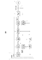
- FIG. 1 is a diagram showing an example of a functional block of a drive device of a rotary electric machine according to the first embodiment of the present invention.
- a power converter composed of a drive transistor such as an IGBT (Insulated Gate Bipolar Transistor) and a power device such as a diode and a control for the power converter are shown.
- the configuration is shown in a block diagram of the voltage output device 3, and detailed illustration is omitted.
- the rotary electric machine has a configuration in which the synchronous machine 4 is used in FIG. 1, but as shown in FIGS. 18 to 20 described later, an induction machine other than the synchronous machine may be used.
- the voltage output device 3 is based on a switching command from the control device 2 via a drive circuit and a main circuit (not shown, but included in the voltage output device 3).
- a three-phase AC voltage is applied to the synchronous machine 4.
- a drive current flows through the synchronous machine 4 by applying a three-phase AC voltage from the voltage output device 3, and a rotational torque is generated.
- the current detector 5 is composed of a Hall CT (Current Transformer) or the like, and detects waveforms of U-phase, V-phase, and W-phase three-phase currents i u , iv , and i w flowing through the synchronous machine 4, respectively.
- a Hall CT Current Transformer
- the control device 2 is equipped with a control program for driving and controlling the synchronous machine 4 connected as a load.
- a control program for driving and controlling the synchronous machine 4 connected as a load.
- the torque command calculation unit 11 outputs the torque command value ⁇ m * in response to the operation command from the host device.
- the current command calculation unit 10 outputs the current command values id * and i q * of the dq axis for obtaining a predetermined torque with respect to the torque command value ⁇ m * .
- the current detection coordinate conversion unit 8 uses the d-axis estimated phase ⁇ dc recognized by the control device 2 to rotate the three-phase currents i u , iv and i w of the synchronous machine 4 detected by the current detector 5. Is converted into the dq coordinates of, and is output to the current control unit 9 as dq-axis current detection values (i df and i qf ).
- PI Proportional-Integralal
- the voltage command coordinate conversion unit 12 uses the dq-axis voltage command value output by the current control unit 9 and the d-axis estimated phase ⁇ dc to generate three-phase AC voltage command values v u * , v v * , and v w * . Output.
- the PWM control unit 7 gives a PWM voltage (Pulse Width Modulation) switching command to the voltage output device 3 based on the three-phase AC voltage command values v u * , v v * , and v w * output by the voltage command coordinate conversion unit 12. Is output.
- PWM voltage Pulse Width Modulation
- the phase synchronization control unit 14 Based on the phase deviation information ⁇ c , the phase synchronization control unit 14 outputs an angular velocity estimated value ⁇ 1 ⁇ so as to make the phase deviation information ⁇ c zero. At the same time, although the details will be described later, the acceleration / deceleration component phase deviation compensation amount ⁇ is output.
- the phase deviation information ⁇ c indicates the difference between the phase estimated value ⁇ dc and the rotor phase ⁇ d of the synchronous machine 4.
- the phase deviation information ⁇ c is the phase estimated value ⁇ est by sensorless control, or the phase estimated value ⁇ dc using the information of the phase detection value ⁇ r by a resolver or the like, although not shown. Either of the configurations may be used in which the difference between the above is calculated and the phase deviation information ⁇ c is obtained.
- phase deviation estimated value ⁇ est for example, a method of estimating based on a high frequency current detection value when a high frequency voltage is superimposed in a low speed range, or a method of estimating based on a high frequency current detection value in a high speed range, or an induced voltage of a rotating electric machine is used in a high speed range. Use the estimation method.
- the slipping slip detection determination unit 15 determines slipping slip detection based on the acceleration / deceleration phase deviation compensation amount ⁇ output from the phase synchronization control unit 14, and outputs the slip slip detection signal to the torque command calculation unit 11. ..
- the torque command calculation unit 11 receives the slip detection signal, it promptly narrows down the torque command value ⁇ m * to converge the slip generated between the wheels, which are the driving wheels, and the rails, and rail the wheels. Re-adhere to.
- the phase calculation unit 13 integrates the angular velocity estimated value ⁇ 1 ⁇ output from the phase synchronization control unit 14, and outputs the phase estimated value ⁇ dc .
- FIG. 2 is a diagram showing a schematic configuration of a bogie for a railroad vehicle.
- the bogie 31 is equipped with a synchronous machine 4, and the rotor shaft 30 of the synchronous machine 4 transmits power to the small gear 32 via the joint 34.
- the axle 35 is rotated by the reduction gear composed of the small gear 32 and the large gear 33, and the wheels 27 connected to the axle 35 are rotated.
- the wheels 27 accelerate the vehicle by transmitting the force to the bogie 31 by the tangential force generated on the wheels 27 as the reaction force that the wheel tread receives from the rail 36.
- FIG. 3 is a diagram showing a functional block of the equation of motion of the vehicle and one wheel set.
- the equation of motion of the vehicle body and the motor is shown in the block diagram in consideration of the adhesion due to the tangential force coefficient ⁇ between the wheel and the rail, which are the driving wheels, due to the motor torque.
- the force for rotating the wheels is determined by the difference between the wheel torque and the tangential force torque
- the force for accelerating the vehicle is determined by the difference between the tangential force and the running resistance, which change according to the tangential force coefficient ⁇ .
- FIG. 4 is a diagram showing the relationship between the slip speed between the wheel and the rail and the tangential force coefficient ⁇ .
- the tangential force coefficient ⁇ changes according to the slip speed, which is the difference between the wheel peripheral speed and the vehicle body speed. Further, in rainy weather, the tangential force coefficient ⁇ decreases as compared with in fine weather, and slipping is likely to occur. Further, it is known that the tangential force coefficient ⁇ changes not only in rainy weather but also by oil content, fallen leaves and dust on the rail surface, and also by vehicle speed.
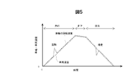
- FIG. 5 is a diagram showing slipping of a railroad vehicle during power running and regeneration.
- the tangential force coefficient ⁇ decreases due to the influence of rain or the like, the force for accelerating the vehicle in FIG. 3 remains small, but only the force for rotating the wheels increases, and the slip speed increases. Then, when the inflection point of the tangential force coefficient ⁇ shown in FIG. 4 is exceeded, idling occurs. Since the tangential force coefficient ⁇ has a negative slope with respect to the slip speed, once slip occurs, the slip will continue to increase in the expanding direction. The above is about power running, but at the time of regeneration, as shown in FIG. 5, gliding occurs in the same manner.
- FIG. 6 is a diagram showing a phase deviation generated during acceleration / deceleration of the vehicle.
- the phase deviation ⁇ is defined by the following equation (Equation 1) as the deviation between the rotor phase ⁇ d of the synchronous machine 4 and the phase estimation value ⁇ dc of the control.
- Equation 1 the phase deviation between the rotor phase ⁇ d of the synchronous machine 4 and the phase estimation value ⁇ dc of the control.
- s is a Laplace operator
- ⁇ r is the rotor angular velocity of the synchronous machine 4.
- the phase synchronization control unit 14 is configured by general PI control
- the proportional gain and the integrated gain in the phase synchronization control unit 14 are K P and KI, respectively
- the angular velocity estimated value ⁇ 1 ⁇ can be calculated by the following equation (Equation 2 ) based on the phase deviation information ⁇ c .
- the rotor angular velocity ⁇ r of the synchronous machine 4 can be calculated by the following equation (Equation 3) from the motor torque ⁇ m and the moment of inertia J.
- P m is the pole logarithm of the synchronous machine 4.
- the moment of inertia J is treated as an equivalent moment of inertia obtained by synthesizing the vehicle mass and the adhesion due to the tangential force coefficient ⁇ when viewed from the motor shaft shown in FIG.
- the moment of inertia J is large, and when slipping occurs between the wheel and rail, it is treated as if the moment of inertia J is small when viewed from the motor shaft.
- Equation 5 Assuming that the phase deviation information ⁇ c recognized by the control device 2 matches the phase deviation ⁇ , the following equation (Equation 5) is obtained.
- phase-locked loop control unit 14 when configured by general PI control, as described using (Equation 1) to (Equation 6), it corresponds to the torque ⁇ m , the moment of inertia J , and the integrated gain KI.
- FIG. 7 is a diagram showing a current vector when a phase deviation ⁇ occurs between the rotor phase ( ⁇ d ) and the control phase estimated value ( ⁇ dc ).
- the reference phase of the rotor of the synchronous machine 4 is set as the d -axis
- the reference phase of the rotor estimated by the control device 2 is set as the dc axis
- the current command values id * and i q * when the phase deviation ⁇ occurs, the current command values id * and i q *.
- the currents that actually flow are id and i q
- the torque ⁇ m actually output by the motor has a large error with respect to the torque command value ⁇ m * .
- a section for compensating for the deviation amount due to the acceleration component is provided in the sensorless control.
- a configuration for detecting slipping without using differential processing will be described using the output value of the term for compensating for the acceleration component.
- FIG. 8 is a diagram showing an example of a functional block of the phase synchronization control unit 14 according to the first embodiment.
- the phase synchronization control unit 14 includes a constant speed phase deviation convergence unit 20 capable of converging the phase deviation to zero at a constant speed, and an acceleration / deceleration phase deviation convergence unit 21 capable of converging the phase deviation during acceleration / deceleration.
- the acceleration / deceleration phase deviation convergence unit 21 inputs the phase deviation amount (before compensation) ⁇ c0 , which is the difference between the phase deviation information ⁇ c and the phase deviation target value, and outputs the acceleration / deceleration component phase deviation compensation amount ⁇ ⁇ . ..
- the constant speed phase deviation convergence unit 20 inputs the phase deviation amount (after compensation) ⁇ c ' , which is the sum of the phase deviation amount (before compensation) ⁇ c0 and the acceleration / deceleration component phase deviation compensation amount ⁇ , and the angular velocity.
- the estimated value ⁇ 1 ⁇ is output.
- FIG. 9 is a diagram showing an example of the functional block of the above-mentioned constant-speed phase deviation convergence unit 20. PI control is performed using the proportional gain K P and the integrated gain KI.
- FIG. 10 is a diagram showing an example of the functional block of the phase deviation converging unit 21 during acceleration / deceleration. Integral gain K II is used for integration.
- the phase synchronization control unit 14 calculates the estimated angular velocity value ⁇ 1 ⁇ from the phase deviation ⁇ c as in the first embodiment.
- the order of the transfer function to be performed may be composed of a quadratic or higher as shown in the following equation (Equation 7).
- Equation 8 Similar to (Equation 5), the following equation (Equation 8) can be obtained by rearranging the equations for the phase deviation ⁇ 'in the first embodiment.
- phase deviation converging unit 21 during acceleration / deceleration operates so that K II / s outputs a compensation amount so that the steady deviation of the phase deviation ⁇ of (Equation 6) becomes zero, so that the output (acceleration / deceleration) is output.
- the fractional phase deviation compensation amount) ⁇ has the relation of the following equation (Equation 10).
- FIG. 11 is a diagram showing an example of the effect of adding compensation by the phase deviation converging unit 21 during acceleration / deceleration.
- the steady deviation of the phase during acceleration / deceleration can be converged to zero by the phase deviation compensation amount ⁇ for the acceleration / deceleration component, which is the output of the phase deviation convergence unit 21 during acceleration / deceleration. Even when slipping occurs and the acceleration / deceleration becomes high, it is possible to prevent the phase deviation from expanding and prevent control instability and deterioration of torque accuracy.
- the acceleration / deceleration component phase deviation compensation amount ⁇ ⁇ which is the output of the acceleration / deceleration phase deviation convergence unit 21, is the vehicle mass and tangential force when viewed from the motor shaft when the torque ⁇ m and the integral gain KI are known. It will change according to the equivalent moment of inertia J including the coefficient ⁇ .
- the inventors can obtain information equivalent to acceleration from the phase deviation information without using differential processing. He found out what he could get and devised a method to detect slipping based on this information.
- FIG. 12 is a diagram showing a method of detecting idling by the output of the phase deviation converging portion during acceleration / deceleration when idling occurs. Since the moment of inertia J seems to have decreased sharply during idling with respect to the phase deviation ⁇ in the normal adhesive state, ⁇ of the output value of the phase deviation converging portion 21 during acceleration / deceleration represented by (Equation 10). ⁇ also increases.
- FIG. 13 is a diagram showing an example of a functional block of the slipping detection determination unit 15.
- the acceleration / deceleration component phase deviation compensation amount ⁇ output by the phase synchronization control unit 14 exceeds the judgment value (slip judgment threshold value or gliding judgment threshold value) of the acceleration component of the phase deviation assumed in the normal adhesive state. It is considered that slipping has occurred, and the slipping detection signal is output to the torque command calculation unit 11.
- the idling determination threshold value or the sliding determination threshold value is set to a degree that is larger than the compensation amount at the time of acceleration / deceleration in the adhesive state and is not erroneously detected according to the vibration component included in the phase deviation information.
- FIG. 14 is a diagram showing a comparison between the conventional configuration for detecting slipping and the configuration of the present invention. The differences in configuration and effect between the prior art and the present invention will be described below with reference to FIG.
- the conventional phase synchronization control unit 16 has a cutoff frequency, the problem that the detection of slipping is delayed is inevitable. Further, when the differential processing is used to calculate the acceleration, it is necessary to provide a low-pass filter processing as in Patent Document 1 and Patent Document 2 as a noise countermeasure, and the detection of slipping is delayed. Is clear.
- the present invention has a configuration in which an acceleration component of the phase deviation estimated value ⁇ est before calculating the frequency estimated value is extracted to detect slipping. Therefore, slipping can be detected earlier than the conventional configuration.
- the sensorless control is performed without causing the torque error due to the phase deviation as described with reference to FIG. It also has the effect of stabilizing and improving torque accuracy.
- FIG. 15 is a diagram showing an example of the functional block of the phase synchronization control unit 14a which is a modification of the first embodiment
- FIG. 16 is an example of the functional block of the constant speed phase deviation convergence unit 20a in the phase synchronization control unit 14a
- FIG. 17 is a diagram showing an example of a functional block of the phase deviation converging unit 21a at the time of acceleration / deceleration in the phase synchronization control unit 14a.
- the phase synchronization control unit 14a has the phase deviation amount (before compensation) ⁇ c0 in parallel with the constant speed phase deviation convergence unit 20a and the acceleration / deceleration phase deviation convergence unit 21a. Entered.
- the phase deviation converging unit 21a at the time of acceleration / deceleration calculates the angular velocity estimated value ⁇ 1 ⁇ from the phase deviation ⁇ c by providing the squared term of 1 / s as shown in FIG.
- the order of the denominator of the transfer function is quadratic. This has the effect of suppressing the phase deviation ⁇ during acceleration / deceleration.
- the order of the denominator of the transfer function is quadratic or higher, the order may be any order as long as the terms of the quadratic or higher are included, and the phase-locked loop control unit 14 starts from FIG.
- the configuration is not necessarily limited to the configuration shown in FIG. 10 or FIGS. 15 to 17.
- phase synchronization control unit 14 is configured as the phase deviation information ⁇ c by calculating the difference from the phase estimated value ⁇ dc using the information of the phase detection value ⁇ r by the resolver or the like, the acceleration / deceleration of the vehicle is in progress. Similarly, since the steady phase deviation remains, it can be applied even in the configuration of the control with a resolver or the control with a speed sensor.
- the synchronous machine 4 has been described as an example of the rotary electric machine, but the present invention is not limited to the synchronous machine, and can be applied to other rotary electric machines such as an induction machine.
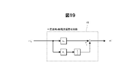
- FIG. 18 is a diagram showing an example of a functional block of the frequency estimation control unit 40 when the first embodiment is applied to the drive device of the induction machine
- FIG. 19 is a diagram showing a constant speed q-axis current deviation in the frequency estimation control unit 40.
- FIG. 20 is a diagram showing an example of a functional block of the convergence unit 41
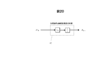
- FIG. 20 is a diagram showing an example of a functional block of the q-axis current deviation convergence unit 42 during acceleration / deceleration in the frequency estimation control unit 40.
- the q-axis current deviation due to acceleration is used as the q-axis current deviation converging unit 42 during acceleration / deceleration.
- the configuration is such that the amount is compensated. That is, if the configuration is such that slipping is detected based on the acceleration / deceleration component q-axis current deviation compensation amount ⁇ i q_ ⁇ , which is the output of the q-axis current deviation converging unit 42 during acceleration / deceleration, slipping is performed while stabilizing the speed estimation control. Can be obtained at an early stage.
- the state quantity used for inputting the calculation of the estimated angular velocity value during acceleration / deceleration of the rotary electric machine (in the case of a synchronous machine, the estimated phase of the rotor, in the case of an inducer, the inducer is used.
- the present invention is configured to output a compensation value for correcting the state amount in order to suppress the deviation amount generated in the flowing current) to substantially zero, and to detect slipping when the compensation value exceeds a predetermined value. The effect of can be obtained.
- the drive device of the rotary electric machine is a voltage output device 3 that outputs a voltage to the synchronous machine 4, and a control that controls the output voltage of the voltage output device 3 based on the torque command value ⁇ m * .
- the control device 2 includes a device 2 and a phase synchronization control unit 14 that outputs an angular velocity estimated value ⁇ 1 ⁇ from the phase deviation information of the rotor.
- the phase synchronization control unit 14 has an acceleration / deceleration phase deviation convergence unit 21 that suppresses a steady deviation of the estimated phase during acceleration / deceleration, and is driven by the synchronous machine 4 based on the output of the acceleration / deceleration phase deviation convergence unit 21.
- the slipping slip detection determination unit 15 for detecting the slipping state of the wheels to be slid is provided. This makes it possible to realize high-speed idling slip detection while stabilizing the control system even during slipping. Further, in the case of the inducer, the same effect can be obtained by replacing the phase deviation with the q-axis current deviation.
- the second embodiment according to the present invention is different from the first embodiment in that the determination threshold value for detecting idling slip by the idling slip detection determination unit 15 is made variable according to the operating state of the vehicle and the surrounding environment. ..
- an appropriate slipping determination threshold value can be set, and slipping is performed more than in the first embodiment. While preventing erroneous detection, it is possible to further speed up the detection of slipping.
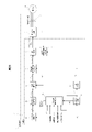
- FIG. 21 is a diagram showing an example of a functional block of the drive device of the rotary electric machine according to the second embodiment.
- the torque command value ⁇ m * the occupancy rate information, the weather information, the position information in the formation, and the angular velocity estimated value ⁇ 1 ⁇ are input to the slip slip detection determination unit 15 to make the slip slip determination threshold variable. ..
- FIG. 22 is a diagram showing an example of a functional block of the slipping detection determination unit 15 according to the second embodiment.
- the value obtained by dividing the torque command value ⁇ m * by the integrated gain KI and the moment of inertia J is defined as the slip slip determination threshold value according to the calculation formula (Equation 10).
- the occupancy rate information is calculated by the equivalent moment of inertia calculation unit 50 into the equivalent moment of inertia J.
- the weather information correction gain calculation unit 51 that inputs the weather information calculates the weather information correction gain and outputs it as one of the correction gains of the slip slip determination threshold value.
- the axle 35 to which the rotary electric machine is connected is connected to the traveling direction in the same manner as the principle that the tangential force coefficient ⁇ changes according to the weather, that is, the condition of the road surface (rail surface).
- the weather that is, the condition of the road surface (rail surface).
- the axle 35 to which the rotary electric machine is connected is located on the rear side with respect to the traveling direction, slipping tends to be relatively unlikely to occur even in rainy weather or the like.
- the traveling direction of the formation itself and the car number on which the axle 35 to which the rotary electric machine is connected can be discriminated, it is possible to adjust to an appropriate idling gliding determination threshold. For example, if it is located on the side of the first car in the direction of travel, it will be easier to slip, so the judgment threshold will be lowered, and if it is located on the side of the car behind in the direction of travel, it will be difficult to slip. Increase the judgment threshold. By doing so, it is possible to set an appropriate determination threshold value according to the position of the vehicle having the axle in the formation, and it is possible to realize higher speed detection while preventing false detection of slipping.
- the in-organization position information correction gain calculation unit 52 that inputs the in-organization position information calculates the in-organization position information correction gain and outputs it as one of the correction gains of the slip slip determination threshold value.
- the tangential force coefficient ⁇ has a dependence on the vehicle speed (see the tangential force coefficient table shown in FIG. 3), and as the vehicle speed increases, the tangential force coefficient ⁇ increases. It becomes smaller.
- the running resistance also increases as the speed increases, and the wheels are more likely to slip. Therefore, for example, when the angular velocity estimated value ⁇ 1 ⁇ becomes high, it becomes easy to slip and slide, so the judgment threshold value is lowered, and when the angular velocity estimated value ⁇ 1 ⁇ becomes low, it becomes difficult to slip. Increase the judgment threshold.
- the frequency of the rotary electric machine or the vehicle speed may be directly used. By doing so, it is possible to set an appropriate determination threshold value according to the vehicle speed, and it is possible to realize higher speed detection while preventing false detection of slipping.
- the speed correction gain calculation unit 53 that inputs the angular velocity estimated value ⁇ 1 ⁇ calculates the running resistance correction gain and outputs it as one of the correction gains of the slip slip determination threshold value.
- the means for adjusting these determination threshold values may be any method as long as the idling / sliding determination threshold value is changed according to each parameter, such as an arithmetic expression or a table for each parameter.
- the value obtained by reversing the sign is used as the determination threshold value, but a correction gain calculation may be provided individually for idling and gliding.
- the torque command value ⁇ m * , the occupancy rate information, the weather information, the position information in the formation, and the angular velocity estimated value ⁇ 1 ⁇ are taken into the slipping slip detection determination unit 15, and the values are responsive to these information. Therefore, the determination threshold value for detecting slipping is made variable. As a result, it is possible to further increase the speed of idling gliding detection while preventing false detection of idling gliding. [Embodiment 3]
- the third embodiment according to the present invention is different from the second embodiment in that an upper / lower limit limiter is provided for the output of the phase deviation converging unit 21 during acceleration / deceleration.
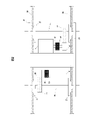
- FIG. 23 is a diagram showing an example of a functional block of the drive device of the rotary electric machine according to the third embodiment.
- the slip slip determination threshold value is output from the slip slip detection determination unit 15 and input to the phase synchronization control 14, and the upper and lower limit values are calculated with respect to the output of the phase deviation convergence unit 21 during acceleration / deceleration. Used for.
- FIG. 24 is a diagram showing an example of a functional block of the slipping detection determination unit 15 according to the third embodiment. A function of outputting a determination threshold value for detecting idling slip has been added to the idling slip detection determination unit 15 according to the second embodiment shown in FIG. 22.
- FIG. 25 is a diagram showing an example of a functional block of the phase deviation converging unit 21 during acceleration / deceleration according to the third embodiment.
- the upper and lower limit limiters 22 are provided for the output of the acceleration / deceleration component phase deviation compensation amount ⁇ .
- the set value of the upper and lower limit limiters 22 is set so as to be slightly larger than the level at which the slip detection is determined by multiplying the slip slip determination threshold by the determination threshold adjustment gain.
- the upper limit value of the upper and lower limit limiter 22 is set based on the judgment threshold value at the time of idling, and the lower limit value of the upper / lower limit limiter 22 is set based on the judgment threshold value at the time of sliding.
- FIG. 26 is a diagram showing a comparison of the effects depending on the presence / absence of the upper / lower limit limiter 22 provided in the phase deviation converging portion 21 during acceleration / deceleration.
- phase deviation compensation amount ⁇ for acceleration / deceleration will continue to accumulate until the idling is converged after the idling is detected and the torque is narrowed down. Therefore, even after re-adhesion, it takes time for the acceleration / deceleration phase deviation compensation amount ⁇ to return to the steady value.
- the acceleration / deceleration component phase deviation compensation amount ⁇ is prevented from exceeding, and the acceleration / deceleration after re-adhesion is prevented. It is possible to obtain the effect of accelerating the convergence of the fractional phase deviation compensation amount ⁇ to the steady value.
- the ON time of the idling slip detection timing becomes closer to the actual idling time, which has the effect of being optimized, and there is also a risk of falsely detecting idling slip after re-adhesion. Can be reduced.
- the third embodiment by providing the upper and lower limit limiters 22 at the output of the phase deviation converging unit 21 during acceleration / deceleration, a steady value of the acceleration / deceleration component phase deviation compensation amount ⁇ is provided after re-adhesion control by torque operation. It accelerates the convergence to. This makes it possible to prevent erroneous detection of slipping after re-adhesion.
- Carriage 32 ... Small gears, 33 ... Large gear, 34 ... Joint, 35 ... Axle, 36 ... Rail, 40 ... Frequency estimation control unit, 41 ... Q-axis current deviation convergence unit at constant speed, 42 ... Q-axis current deviation convergence unit during acceleration / deceleration, 50 ... Equivalent inertia moment calculation unit, 51 ... Weather information correction gain calculation unit, 52 ... In-organization position information correction gain calculation unit, 53 ... Speed correction gain calculation unit
Landscapes
- Engineering & Computer Science (AREA)
- Power Engineering (AREA)
- Transportation (AREA)
- Mechanical Engineering (AREA)
- Electric Propulsion And Braking For Vehicles (AREA)
- Control Of Ac Motors In General (AREA)
Abstract
Description
この接線力は、車輪とレール間の粘着状態を表す接線力係数μによって変動し、車輪のトルクが接線力よりも過大となった場合、車両を加速させる力は小さいまま、車輪を回転させる力のみが大きくなり、その結果、車輪の空転または滑走(以下、「空転滑走」と略す)が生じる。特に、雨天時や降雪時には、粘着係数が大きく低下するため、空転滑走が発生し易くなる。
特許文献1に記載の技術は、速度センサレスで、複数台の誘導電動機を並列駆動する制御装置の周波数指令値の時間変化(微分値)から加速度推定値αiを算出している。しかし、特許文献1の段落[0027]に記載のように、ノイズを除去するために、算出した出力周波数について3Hz以下を通過域とする低域通過フィルタ(LPF)演算を行った後、一階微分を行うことで加速度推定値αiを算出している。この低域通過フィルタ演算によって、空転滑走の検知が遅れる課題がある。
上記した以外の課題、構成および効果は、以下の実施をするための形態における説明により明らかにされる。
各実施形態において参照番号が同一のものは、同一の構成要件または類似の機能を備えた構成要件として示している。また、後出の実施形態において、既出の実施形態と同一または類似の構成要件の説明を省略する場合がある。
[実施形態1]
図1では、実施形態1に必要最小限の機能ブロックのみを示し、IGBT(Insulated Gate Bipolar Transistor)等の駆動用トランジスタやダイオード等のパワーデバイスから構成される電力変換器およびこの電力変換器に対する制御構成については、電圧出力装置3としたブロック図で示し、詳細な図示を省略している。
図2は、鉄道車両用の台車の概略構成を示す図である。
台車31には、同期機4が備え付けられており、同期機4の回転子シャフト30が、継手34を介して小歯車32に動力を伝達する。小歯車32と大歯車33とから構成される減速ギアによって車軸35を回転させ、車軸35に接続された車輪27を回転させる。車輪27は、車輪踏面がレール36から受ける反力として車輪27に生じる接線力によって、台車31に力を伝達して車両を加速させる。
モータトルクによって、駆動輪である車輪とレール間の接線力係数μによる粘着を考慮し、車体とモータの運動方程式をブロック図で示している。車輪を回転させる力は、車輪トルクと接線力トルクの差によって決まり、車両を加速させる力は、接線力と走行抵抗の差によって決まり、これらは接線力係数μに応じて変化することになる。
接線力係数μは、車輪周速度と車体速度との差となるスリップ速度に応じて変化する。また、雨天時は、晴天時に対して接線力係数μが低下し、空転滑走が発生し易くなる。また、接線力係数μは、雨天だけではなく、レール面における油分や落ち葉や塵埃によっても変化することや、車両速度によっても変化することが知られている。
図4に示すように、雨天等の影響で接線力係数μが低下した場合、図3の車両を加速させる力は小さいまま、車輪を回転させる力のみが大きくなり、スリップ速度が増加する。その上で、図4に示す接線力係数μの変曲点を超えた場合に、空転が生じる。接線力係数μが、スリップ速度に対して負の傾きを持つため、一度空転が発生すると、空転は拡大する方向に増加し続けることとなる。以上は、力行時についてであるが、回生時には、図5に示すように、同様に滑走が生じる。
図6は、車両の加減速中に発生する位相偏差を示す図である。
まず、加減速時に発生する位相偏差Δθについて説明する。位相偏差Δθを、同期機4の回転子位相θdと制御の位相推定値θdcとの偏差として、次式(数1)で定義する。ただし、sはラプラス演算子で、ωrは同期機4の回転子角速度とする。


同期機4の回転子の基準位相をd軸として、制御装置2が推定する回転子の基準位相をdc軸とし、位相偏差Δθが発生した場合には、電流指令値id *、iq *となるように電流制御するが、実際に流れる電流は、id、iqとなり、トルク指令値τm *に対して、モータが実際に出力するトルクτmは、大きな誤差を持つ。
位相同期制御部14は、一定速時に位相偏差をゼロに収束できる一定速時位相偏差収束部20と、加減速中に位相偏差を収束できる加減速時位相偏差収束部21とから構成される。


加減速時位相偏差収束部21の出力である加減速分位相偏差補償量Δθαによって、図11に示すように、加減速中の位相の定常偏差をゼロに収束できる。空転滑走が発生して、加減速度が高くなった場合でも、位相偏差の拡大を防止し、制御不安定化やトルク精度の低下を防ぐことができる。
通常の粘着状態での位相偏差Δθに対し、空転時には、慣性モーメントJが急激に小さくなったように見えるため、(数10)で表される加減速時位相偏差収束部21の出力値のΔθαも増加する。
位相同期制御部14が出力する加減速分位相偏差補償量Δθαが、通常の粘着状態で想定される位相偏差の加速度成分の判定値(空転判定閾値または滑走判定閾値)を超過した場合に、空転滑走が発生したと見なし、空転滑走検知信号をトルク指令演算部11に出力する。
以下に、従来と本発明との構成・効果の違いを、図14を基に記載する。
先の特許文献1に記載の従来の方式では、従来の位相同期制御部16のPI制御等によって積分処理を実施して周波数推定値を算出した後に、この周波数推定値を微分処理にて微分することによって加速度推定値(dfr/dt)を算出する構成が、一般的によく用いられる。
一方で、本発明では、周波数推定値を演算する前の位相偏差推定値Δθestの加速度成分を抽出して空転滑走を検知する構成である。そのため、従来の構成よりも早期に空転滑走を検知できる。
以上が、従来技術と本発明の構成・効果の違いである。
図15は、実施形態1の変形例である位相同期制御部14aの機能ブロックの一例を示す図、図16は、位相同期制御部14a内の一定速時位相偏差収束部20aの機能ブロックの一例を示す図、図17は、位相同期制御部14a内の加減速時位相偏差収束部21aの機能ブロックの一例を示す図、である。


[実施形態2]
実施形態2では、空転滑走検知判定部15に、トルク指令値τm *、乗車率情報、天候情報、編成内位置情報および角速度推定値ω1 ^を入力し、空転滑走判定閾値を可変にする。
(数10)からわかるように、例えば、トルクτmが小さくなれば、加減速度も低くなり、通常の粘着状態における補償量Δθαも小さくなる。つまり、トルク指令値τm *が大きくなった場合には判定閾値を高くし、トルク指令値τm *が小さくなった場合には判定閾値を低くするように調整することで、トルクの状態に対しても適切な判定閾値をセットすることができ、空転滑走の誤検知を防ぎつつ、更なる高速な検知を実現できる。
接線力(=μ・W・g)は、図3からわかるように、1軸当たりに掛かる重量Wに比例する。重量Wは、乗客の乗車率に応じて変化するため、例えば、乗車率が低くなった場合には空転滑走し易くなるので判定閾値を低くし、乗車率が高くなった場合には空転滑走し難くなるので判定閾値を高くする。このようにすることで、乗車率に応じた適切な判定閾値を設定でき、空転滑走の誤検知を防ぎつつ、更なる高速な検知を実現できる。
図4からわかるように、雨天時は、晴天時に対して接線力係数μが小さくなり、接線力(=μ・W・g)が小さくなる。そのため、例えば、ワイパー動作や天気情報などで外部機器から雨天や降雪の情報を検知した場合には、空転滑走し易くなるので判定閾値を低くする。このようにすることで、雨天や降雪のような天候の変化で路面(レール面)の状況が滑りやすくなった場合においても、更なる高速な検知を実現できる。
図4で、天候すなわち路面(レール面)の状態に応じて接線力係数μが変化する原理と同様に、回転電機が接続される車軸35が、進行方向に対して先頭側に位置する場合には、レール面の雨滴や塵埃等が捌けられておらず、空転滑走が生じやすい傾向にある。一方、回転電機が接続される車軸35が、進行方向に対して後方側に位置する場合には、雨天時などにおいても、空転滑走が比較的生じにくい傾向にある。
接線力係数μは、車両速度に対して依存性を持ち(図3に示す接線力係数テーブル、参照)、車両速度が高くなるに従い、接線力係数μは小さくなる。また、走行抵抗も速度が高くなるに従って増加し、車輪の空転滑走が発生しやすくなる。そのため、例えば、角速度推定値ω1 ^が高くなった場合には、空転滑走し易くなるので判定閾値を低くし、角速度推定値ω1 ^が低くなった場合には、空転滑走し難くなるので判定閾値を高くする。また、角速度推定値ω1 ^に替えて、回転電機の周波数または車両速度を直接用いるようにしてもよい。このようにすることで、車両速度に応じた適切な判定閾値を設定でき、空転滑走の誤検知を防ぎつつ、更なる高速な検知を実現できる。
[実施形態3]
実施形態3では、空転滑走判定閾値が、空転滑走検知判定部15から出力され、位相同期制御14に入力され、加減速時位相偏差収束部21の出力に対して上限および下限のリミット値の演算に用いられる。
図22に示す実施形態2に係る空転滑走検知判定部15に、空転滑走を検知する判定閾値を出力する機能が追加されている。
実施形態3では、加減速分位相偏差補償量Δθαの出力に上下限リミッタ22を設ける。この上下限リミッタ22のセット値としては、空転滑走判定閾値に判定閾値調整ゲインを乗算することにより、空転検知と判定するレベルよりも僅かに大きい値になるように設定する。
Claims (18)
- 回転電機へ駆動電圧を出力する電圧出力装置と、
前記回転電機に流れる電流を検出する電流検出器と、
前記回転電機の回転子の角速度を推定演算する角速度推定機能と
を備え、
前記制御装置は、
前記回転電機の加減速中に前記角速度を推定演算するための入力となる状態量に生じる定常偏差を略ゼロに抑制するために当該状態量を補正する補償値を演算し、
前記補償値が、所定値を超えた場合に前記回転電機により駆動される駆動輪の空転または滑走を検知する
ことを特徴とする回転電機の駆動装置。 - 請求項1に記載の回転電機の駆動装置であって、
前記制御装置は、前記空転または前記滑走を検知すると前記回転電機に対するトルク指令値を絞り込む
ことを特徴とする回転電機の駆動装置。 - 請求項1または2に記載の回転電機の駆動装置であって、
前記回転電機は、同期電動機であり、
前記状態量は、前記回転子の位相と前記制御装置で推定する前記回転子の位相推定値との差を示す位相偏差推定値であり、
前記制御装置は、
前記位相偏差推定値に対して、前記同期電動機の加減速中に定常的に発生する当該位相偏差推定値の前記定常偏差を略ゼロに抑制するための前記補償値として演算した位相偏差補償値を加算し、当該位相偏差補償値を加算した前記位相偏差推定値に基づいて前記角速度推定値を演算すると共に、
前記位相偏差補償値に基づいて前記同期電動機により駆動される駆動輪の空転または滑走を検知する
ことを特徴とする回転電機の駆動装置。 - 請求項1または2に記載の回転電機の駆動装置であって、
前記回転電機は、誘導電動機であり、
前記状態量は、前記誘導電動機に流れる電流の電流検出値であり、
前記制御装置は、
前記電流検出値と電流指令値との電流偏差に対して、前記誘導電動機の加減速中に定常的に発生する当該電流偏差の前記定常偏差を略ゼロに抑制するための前記補償値として演算した電流偏差補償値を加算し、当該電流偏差補償値を加算した前記電流偏差に基づいて前記角速度推定値を演算すると共に、
前記電流偏差補償値に基づいて前記誘導電動機により駆動される駆動輪の空転または滑走を検知する
ことを特徴とする回転電機の駆動装置。 - 請求項1から4のいずれか1項に記載の回転電機の駆動装置であって、
前記制御装置は、
前記空転または前記滑走を検知するための判定閾値を、前記回転電機に対するトルク指令値に応じて可変とし、当該トルク指令値の増加に伴い高く設定し、当該トルク指令値の減少に伴い低く設定する
ことを特徴とする回転電機の駆動装置。 - 請求項1から5のいずれか1項に記載の回転電機の駆動装置であって、
前記制御装置は、
前記空転または前記滑走を検知するための判定閾値を、前記角速度推定値、前記回転電機の周波数または前記回転電機を搭載する鉄道車両の車両速度のいずれか一つに応じて可変とし、前記角速度推定値、前記周波数または前記車両速度のいずれか一つの増加に伴い高く設定し、前記角速度推定値、前記周波数または前記車両速度のいずれか一つの減少に伴い低く設定する
ことを特徴とする回転電機の駆動装置。 - 請求項1から6のいずれか1項に記載の回転電機の駆動装置であって、
前記制御装置は、
前記空転または前記滑走を検知するための判定閾値を、前記回転電機を搭載する鉄道車両の乗客の乗車率に応じて可変とし、前記乗車率の増加に伴い高く設定し、前記乗車率の減少に伴い低く設定する
ことを特徴とする回転電機の駆動装置。 - 請求項1から7のいずれか1項に記載の回転電機の駆動装置であって、
前記制御装置は、
前記空転または前記滑走を検知するための判定閾値を、天候情報に応じて可変とし、晴天の場合には高く設定し、雨天や降雪の場合には低く設定する
ことを特徴とする回転電機の駆動装置。 - 請求項1から8のいずれか1項に記載の回転電機の駆動装置であって、
前記制御装置は、
前記空転または前記滑走を検知するための判定閾値を、列車編成内における前記回転電機を搭載する鉄道車両の号車と進行方向とを示す編成内位置情報に応じて可変とし、前記編成内位置情報が列車の進行方向に対して先頭側に位置する場合には低く設定し、前記編成内位置情報が列車の進行方向に対して後方側に位置する場合には高く設定する
ことを特徴とする回転電機の駆動装置。 - 請求項1から9のいずれか1項に記載の回転電機の駆動装置であって、
前記制御装置は、
前記補償値を、上下限リミッタを通して出力する
ことを特徴とする回転電機の駆動装置。 - 請求項10に記載の回転電機の駆動装置であって、
前記制御装置は、
前記上下限リミッタの上下限値を、請求項5から請求項9のいずれか1項に記載の前記判定閾値に基づいて設定する
ことを特徴とする回転電機の駆動装置。 - 請求項1から11のいずれか1項に記載の回転電機の駆動装置を搭載した鉄道車両。
- 回転電機へ駆動電圧を出力する電圧出力装置を制御する制御装置の駆動方法であって、
前記電圧出力装置の出力電圧を制御する際に、前記回転電機の回転子の角速度を推定演算するステップを有し、
前記ステップには、
前記回転電機の加減速中に前記角速度を推定演算するための入力となる状態量に生じる定常偏差を略ゼロに抑制するために当該状態量を補正する補償値を演算する第1のステップと、
前記補償値が所定値を超えた場合に前記回転電機により駆動される駆動輪の空転または滑走を検知する第2のステップと
が含まれる
ことを特徴とする回転電機の駆動方法。 - 請求項13に記載の回転電機の駆動方法であって、
前記空転または前記滑走を検知すると前記回転電機のトルク指令値を絞り込むステップを有する
ことを特徴とする回転電機の駆動方法。 - 請求項13または14に記載の回転電機の駆動方法であって、
前記回転電機が同期電動機である場合に、
前記状態量は、前記回転子の位相と前記回転子の位相推定値との差を示す位相偏差推定値であり、
前記第1のステップには、
前記同期電動機の加減速中に定常的に発生する前記位相偏差推定値の前記定常偏差を略ゼロに抑制するために前記補償値として位相偏差補償値を演算するステップと、
前記位相偏差補償値を前記位相偏差推定値に加算するステップと、
前記位相偏差補償値を加算した前記位相偏差推定値に基づいて前記角速度推定値を演算するステップと
が含まれる
ことを特徴とする回転電機の駆動方法。 - 請求項13または14に記載の回転電機の駆動方法であって、
前記回転電機が誘導電動機である場合に、
前記状態量は、前記誘導電動機に流れる電流の電流検出値であり、
前記第1のステップには、
前記誘導電動機の加減速中に定常的に発生する、前記電流検出値と電流指令値との電流偏差の前記定常偏差を略ゼロに抑制するために前記補償値として電流偏差補償値を演算するステップと、
前記電流偏差補償値を前記電流偏差に加算するステップと、
前記電流偏差補償値を加算した前記電流偏差に基づいて前記角速度推定値を演算するステップと
が含まれる
ことを特徴とする回転電機の駆動方法。 - 請求項13から16のいずれか1項に記載の回転電機の駆動方法であって、
前記第2のステップは、当該空転または当該滑走を検知するための判定閾値を設け、当該判定閾値を、前記トルク指令値、前記角速度推定値と前記回転電機の周波数と前記回転電機を搭載する鉄道車両の車両速度の内のいずれか一つ、前記回転電機を搭載する鉄道車両の乗客の乗車率、天候情報および列車編成内における前記回転電機を搭載する鉄道車両の号車と進行方向とを示す編成内位置情報、の少なくともいずれか一つに応じて可変とする
ことを特徴とする回転電機の駆動方法。 - 請求項17に記載の回転電機の駆動方法であって、
前記第1のステップには、
前記補償値の演算に続いて、当該補償値を、前記判定閾値に基づいて設定する上下限値を有するリミッタを通して出力するステップが含まれる
ことを特徴とする回転電機の駆動方法。
Priority Applications (3)
| Application Number | Priority Date | Filing Date | Title |
|---|---|---|---|
| JP2022566924A JPWO2022118822A1 (ja) | 2020-12-04 | 2021-11-30 | |
| CN202180081292.4A CN116547164A (zh) | 2020-12-04 | 2021-11-30 | 旋转电机的驱动装置、驱动方法以及铁道车辆 |
| EP21900575.8A EP4258540A1 (en) | 2020-12-04 | 2021-11-30 | Drive device and drive method for rotary electric machine, and railway vehicle |
Applications Claiming Priority (2)
| Application Number | Priority Date | Filing Date | Title |
|---|---|---|---|
| JP2020201959 | 2020-12-04 | ||
| JP2020-201959 | 2020-12-04 |
Publications (1)
| Publication Number | Publication Date |
|---|---|
| WO2022118822A1 true WO2022118822A1 (ja) | 2022-06-09 |
Family
ID=81853196
Family Applications (1)
| Application Number | Title | Priority Date | Filing Date |
|---|---|---|---|
| PCT/JP2021/043765 WO2022118822A1 (ja) | 2020-12-04 | 2021-11-30 | 回転電機の駆動装置、駆動方法および鉄道車両 |
Country Status (4)
| Country | Link |
|---|---|
| EP (1) | EP4258540A1 (ja) |
| JP (1) | JPWO2022118822A1 (ja) |
| CN (1) | CN116547164A (ja) |
| WO (1) | WO2022118822A1 (ja) |
Citations (2)
| Publication number | Priority date | Publication date | Assignee | Title |
|---|---|---|---|---|
| JP2011193568A (ja) * | 2010-03-12 | 2011-09-29 | Fuji Electric Co Ltd | 電気車制御装置 |
| JP2012120320A (ja) * | 2010-11-30 | 2012-06-21 | Toshiba Corp | 回転センサレス制御装置 |
-
2021
- 2021-11-30 CN CN202180081292.4A patent/CN116547164A/zh active Pending
- 2021-11-30 WO PCT/JP2021/043765 patent/WO2022118822A1/ja active Application Filing
- 2021-11-30 JP JP2022566924A patent/JPWO2022118822A1/ja active Pending
- 2021-11-30 EP EP21900575.8A patent/EP4258540A1/en active Pending
Patent Citations (2)
| Publication number | Priority date | Publication date | Assignee | Title |
|---|---|---|---|---|
| JP2011193568A (ja) * | 2010-03-12 | 2011-09-29 | Fuji Electric Co Ltd | 電気車制御装置 |
| JP2012120320A (ja) * | 2010-11-30 | 2012-06-21 | Toshiba Corp | 回転センサレス制御装置 |
Also Published As
| Publication number | Publication date |
|---|---|
| JPWO2022118822A1 (ja) | 2022-06-09 |
| CN116547164A (zh) | 2023-08-04 |
| EP4258540A1 (en) | 2023-10-11 |
Similar Documents
| Publication | Publication Date | Title |
|---|---|---|
| JP4770538B2 (ja) | 電気駆動車両、及び電気駆動車両の制御方法 | |
| JP4573835B2 (ja) | 電気車制御装置 | |
| US5677610A (en) | Control apparatus for electric vehicles | |
| WO2006033181A1 (ja) | 誘導電動機のベクトル制御装置 | |
| EP2599688A1 (en) | Electric power steering device | |
| KR20120048715A (ko) | 전기차의 제어 장치 | |
| JP6540716B2 (ja) | 車両の制御装置および車両の制御方法 | |
| JP2008086085A (ja) | 電気車制御装置 | |
| JP5994705B2 (ja) | 各輪独立駆動台車の各輪モータ制御装置 | |
| JP4850870B2 (ja) | 電気車制御方法及び電気車制御装置 | |
| JP5643271B2 (ja) | 空転滑走発生検出方法及び電動機制御装置 | |
| WO2022118822A1 (ja) | 回転電機の駆動装置、駆動方法および鉄道車両 | |
| JP3933983B2 (ja) | 電気車制御装置 | |
| JP4903740B2 (ja) | 電動機制御方法及び電動機制御装置 | |
| JP2002095299A (ja) | 電車の駆動制御装置 | |
| JP6064727B2 (ja) | 各輪独立駆動台車の制御装置 | |
| JP5195889B2 (ja) | 電気駆動車両 | |
| JP4131785B2 (ja) | 電気車の駆動制御装置及び空転制御方法 | |
| JP4818244B2 (ja) | 電動機制御装置及び再粘着制御方法 | |
| WO2024029310A1 (ja) | 車両制御装置、車両制御方法および車両制御システム | |
| JP7105608B2 (ja) | 電動機制御方法及び電動機制御装置 | |
| JP5344195B2 (ja) | 電気駆動車両 | |
| JP2000253506A (ja) | 速度センサレス制御を用いた電気車制御装置 | |
| JP4342878B2 (ja) | 電気車制御装置 | |
| JPWO2022118822A5 (ja) |
Legal Events
| Date | Code | Title | Description |
|---|---|---|---|
| 121 | Ep: the epo has been informed by wipo that ep was designated in this application |
Ref document number: 21900575 Country of ref document: EP Kind code of ref document: A1 |
|
| ENP | Entry into the national phase |
Ref document number: 2022566924 Country of ref document: JP Kind code of ref document: A |
|
| WWE | Wipo information: entry into national phase |
Ref document number: 202180081292.4 Country of ref document: CN |
|
| NENP | Non-entry into the national phase |
Ref country code: DE |
|
| ENP | Entry into the national phase |
Ref document number: 2021900575 Country of ref document: EP Effective date: 20230704 |