WO2022113989A1 - ケース付き全固体電池 - Google Patents
ケース付き全固体電池 Download PDFInfo
- Publication number
- WO2022113989A1 WO2022113989A1 PCT/JP2021/042946 JP2021042946W WO2022113989A1 WO 2022113989 A1 WO2022113989 A1 WO 2022113989A1 JP 2021042946 W JP2021042946 W JP 2021042946W WO 2022113989 A1 WO2022113989 A1 WO 2022113989A1
- Authority
- WO
- WIPO (PCT)
- Prior art keywords
- battery
- solid
- case
- state battery
- conductive sheet
- Prior art date
- Legal status (The legal status is an assumption and is not a legal conclusion. Google has not performed a legal analysis and makes no representation as to the accuracy of the status listed.)
- Ceased
Links
Images




Classifications
-
- H—ELECTRICITY
- H01—ELECTRIC ELEMENTS
- H01M—PROCESSES OR MEANS, e.g. BATTERIES, FOR THE DIRECT CONVERSION OF CHEMICAL ENERGY INTO ELECTRICAL ENERGY
- H01M10/00—Secondary cells; Manufacture thereof
- H01M10/05—Accumulators with non-aqueous electrolyte
- H01M10/056—Accumulators with non-aqueous electrolyte characterised by the materials used as electrolytes, e.g. mixed inorganic/organic electrolytes
- H01M10/0561—Accumulators with non-aqueous electrolyte characterised by the materials used as electrolytes, e.g. mixed inorganic/organic electrolytes the electrolyte being constituted of inorganic materials only
- H01M10/0562—Solid materials
-
- H—ELECTRICITY
- H01—ELECTRIC ELEMENTS
- H01M—PROCESSES OR MEANS, e.g. BATTERIES, FOR THE DIRECT CONVERSION OF CHEMICAL ENERGY INTO ELECTRICAL ENERGY
- H01M50/00—Constructional details or processes of manufacture of the non-active parts of electrochemical cells other than fuel cells, e.g. hybrid cells
- H01M50/20—Mountings; Secondary casings or frames; Racks, modules or packs; Suspension devices; Shock absorbers; Transport or carrying devices; Holders
- H01M50/202—Casings or frames around the primary casing of a single cell or a single battery
-
- H—ELECTRICITY
- H01—ELECTRIC ELEMENTS
- H01M—PROCESSES OR MEANS, e.g. BATTERIES, FOR THE DIRECT CONVERSION OF CHEMICAL ENERGY INTO ELECTRICAL ENERGY
- H01M50/00—Constructional details or processes of manufacture of the non-active parts of electrochemical cells other than fuel cells, e.g. hybrid cells
- H01M50/20—Mountings; Secondary casings or frames; Racks, modules or packs; Suspension devices; Shock absorbers; Transport or carrying devices; Holders
- H01M50/233—Mountings; Secondary casings or frames; Racks, modules or packs; Suspension devices; Shock absorbers; Transport or carrying devices; Holders characterised by physical properties of casings or racks, e.g. dimensions
- H01M50/242—Mountings; Secondary casings or frames; Racks, modules or packs; Suspension devices; Shock absorbers; Transport or carrying devices; Holders characterised by physical properties of casings or racks, e.g. dimensions adapted for protecting batteries against vibrations, collision impact or swelling
-
- H—ELECTRICITY
- H01—ELECTRIC ELEMENTS
- H01M—PROCESSES OR MEANS, e.g. BATTERIES, FOR THE DIRECT CONVERSION OF CHEMICAL ENERGY INTO ELECTRICAL ENERGY
- H01M50/00—Constructional details or processes of manufacture of the non-active parts of electrochemical cells other than fuel cells, e.g. hybrid cells
- H01M50/50—Current conducting connections for cells or batteries
Definitions
- This disclosure relates to an all-solid-state battery with a case.
- all-solid-state batteries Compared to non-aqueous electrolyte batteries that contain an electrolyte as an electrolyte, all-solid-state batteries have a lower risk of ignition during reflow soldering and do not have the problem of electrolyte leakage. Can be safely implemented.
- Japanese Unexamined Patent Publication No. 2009-21965 discloses a lithium ion secondary battery (Patent Document 1).
- the lithium ion secondary battery is composed of a lithium ion secondary battery element and an accommodating member.
- the lithium ion secondary battery element comprises a solid electrolyte sandwiched between the first electrode and the second electrode.
- the accommodating member has a recess for accommodating the lithium ion secondary battery prime field, and includes an insulating base material made of ceramics and a metal lid member.
- the internal space of the accommodating member is filled with a flexible insulating material (epoxy resin, polyimide resin, etc.) so as to surround the lithium ion secondary battery prime field.
- a flexible insulating material epoxy resin, polyimide resin, etc.
- the lithium ion secondary battery has an insulating base material made of ceramic so that it can withstand the heating temperature in the reflow furnace. Further, the volume of the lithium ion secondary battery element changes during charging and discharging. This change in volume causes the problem of destabilizing the voltage of the battery.
- the lithium-ion secondary battery is filled with a soft insulating material such as resin so as to surround the lithium-ion secondary battery body, so that the battery voltage becomes unstable due to the volume change of the lithium-ion secondary battery body. We are trying to solve the problem of becoming.
- Japanese Unexamined Patent Publication No. 2012-185982 discloses an electrochemical cell package and an electrochemical cell (Patent Document 2).
- the electrochemical cell is configured by accommodating a power generation element composed of an active material used as a positive electrode or a negative electrode and an electrolyte using a non-aqueous solvent in a ceramic electrochemical cell package.
- the electrochemical cell can also be made of a metal material for the sealing plate. In that case, the central portion of the sealing plate changes its shape according to the increase in the internal pressure inside the concave container. This can prevent the electrochemical cell from being destroyed.
- the insulating material filled around the lithium ion secondary battery element pushes up the metal lid member to the outside due to the volume expansion of the lithium ion secondary battery element during charging and discharging. There was a risk of deforming it.
- the sealing plate when the sealing plate is made of a metal material, as described above, the central portion of the sealing plate changes its shape according to the increase in the internal pressure inside the concave container. Therefore, the sealing plate may be deformed outward due to the volume expansion of the electrode during charging and discharging.
- the lithium ion secondary battery of Patent Document 1 connects the lithium ion secondary battery body and the conductor portion via a metal wire embedded in an insulating material filled in the internal space of the accommodating member.
- a metal wire embedded in an insulating material filled in the internal space of the accommodating member.
- Patent Document 2 the second electrode layer of the sealing plate and the second connection terminal on the side surface of the concave container are electrically connected via an electrically conductive material such as solder or by seam welding. Is disclosed. In the electrochemical cell of Patent Document 2, the contact with the electrically conductive material or the welding material becomes insufficient due to the volume change due to the expansion and contraction of the power generation element, and the electrical connection may become unstable.
- the all-solid-state battery with a case may include a case, an all-solid-state battery housed in the case, and a restorable conductive sheet housed in the case.
- the case has a ceramic concave container having a bottom and a side wall, a lid material covering the opening of the concave container, a first connection terminal arranged on the outer surface of the case, and a first connection terminal on the outer surface of the case. And a second connection terminal arranged apart from each other may be included.
- the all-solid-state battery is housed between the first battery can having the first flat portion, the second battery can having the second flat portion, and the first battery can and the second battery can, and has a positive electrode layer and a negative electrode layer.
- a power generation element having a solid electrolyte layer arranged between the positive electrode layer and the negative electrode layer may be included.
- the first flat surface portion of the first battery can may be arranged in the internal space of the case so as to face the inner surface of the bottom portion of the concave container.
- the second flat surface portion of the second battery may be arranged in the internal space of the case so as to face the inner surface of the lid material.
- a first conduction path for electrically connecting the first battery can and the first connection terminal may be formed between the first battery can and the first connection terminal.
- a second conduction path that electrically connects the second battery can and the second connection terminal may be formed between the second battery can and the second connection terminal.
- the restorative conductive sheet is arranged at least one of the inner surface of the bottom of the concave container and the first flat surface portion of the first battery can, and the inner surface of the lid material and the second flat surface portion of the second battery can. , A part of the first conduction path or the second conduction path may be configured.
- FIG. 1 is a cross-sectional view of an all-solid-state battery with a case according to the present embodiment.
- FIG. 2 is an enlarged cross-sectional view of the all-solid-state battery shown in FIG.
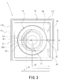
- FIG. 3 is a plan view of the all-solid-state battery with a case shown in FIG.
- FIG. 4 is a plan view of an all-solid-state battery with a case of a modified example.
- FIG. 5 is a cross-sectional view of an all-solid-state battery with a case of a modified example.
- the all-solid-state battery with a case may include a case, an all-solid-state battery housed in the case, and a restorable conductive sheet housed in the case.
- the case has a ceramic concave container having a bottom and a side wall, a lid material covering the opening of the concave container, a first connection terminal arranged on the outer surface of the case, and a first connection terminal on the outer surface of the case. And a second connection terminal arranged apart from each other may be included.
- the all-solid-state battery is housed between the first battery can having the first flat portion, the second battery can having the second flat portion, and the first battery can and the second battery can, and has a positive electrode layer and a negative electrode layer.
- a power generation element having a solid electrolyte layer arranged between the positive electrode layer and the negative electrode layer may be included.
- the first flat surface portion of the first battery can may be arranged in the internal space of the case so as to face the inner surface of the bottom portion of the concave container.
- the second flat surface portion of the second battery can may be arranged in the internal space of the case so as to face the inner surface of the lid material.
- a first conduction path for electrically connecting the first battery can and the first connection terminal may be formed between the first battery can and the first connection terminal.
- a second conduction path that electrically connects the second battery can and the second connection terminal may be formed between the second battery can and the second connection terminal.
- the restorative conductive sheet is arranged at least one of the inner surface of the bottom of the concave container and the first flat surface portion of the first battery can, and the inner surface of the lid material and the second flat surface portion of the second battery can. , A part of the first conduction path or the second conduction path may be configured.
- the all-solid-state battery with a case houses the all-solid-state battery in which the power generation element is housed inside the first battery can and the second battery can, the power generation element is directly housed in the case. It is less susceptible to changes in the volume of the power generation element, and it is possible to prevent the lid material from being pressed and deformed outward during charging and discharging.
- the electrical connection between the first battery can and the first connection terminal and the electrical connection between the second battery can and the second connection terminal are less likely to be affected by the volume change of the power generation element, so that they are electrically connected. It is possible to stabilize the connection.
- the restorable conductive sheet is compressed to relieve the pressing force, so that deformation of the lid material can be prevented.
- the restoring conductive sheet can maintain contact with the all-solid-state battery with a constant force due to its restoring force, and can maintain an electrical connection.
- a gasket may be arranged between the first battery can and the second battery can, and the gasket may be sealed by caulking.
- the gasket By housing the all-solid-state battery in a case having excellent heat resistance and completely sealing it, it is possible to prevent the gasket from deteriorating due to the influence of heat during reflow soldering. Further, even when the sealing property of the gasket is deteriorated, it is possible to prevent moisture from entering the inside of the all-solid-state battery.
- the solid electrolyte layer is a sulfide-based solid electrolyte, it is possible to prevent corrosion due to corrosive hydrogen sulfide gas in an electronic circuit in which an all-solid-state battery with a case is mounted.
- the first conductor portion may be formed through the inside of the bottom portion of the concave container and may be a part of the first conduction path.
- the second conductor portion may be formed so as to penetrate the inside of the side wall portion of the concave container and may be a part of the second conduction path.
- the first connection terminal may be arranged on the outer surface of the bottom of the concave container.
- the second connection terminal may be arranged on the outer surface of the bottom of the concave container apart from the first connection terminal. Thereby, the first connection terminal and the second connection terminal can be arranged on the outer surface of the bottom of the concave container, and the mounting on the surface of the circuit board can be facilitated.
- a restorable conductive sheet may be arranged between the inner surface of the lid material and the second flat surface portion of the second battery can.
- the end portion of the restorable conductive sheet arranged on the lid material side on the second battery can side may be chamfered in a plan view. This makes it possible to prevent the corners of the restorable conductive sheet from coming into contact with the first battery can and causing a short circuit.
- a restorable conductive sheet may be arranged between the inner surface of the lid material and the second flat surface portion of the second battery can.
- the restorative conductive sheet arranged on the lid material side and the second conductor portion may have two or more electrical connections. As a result, the restorative conductive sheet is more firmly connected to the second conductor portion. As a result, even when the restorable conductive sheet is displaced due to expansion and contraction of the all-solid-state battery, it is possible to stabilize the electrical connection.
- the first battery can may be an outer can.
- the second battery can may be a sealing can.
- the restorative conductive sheet arranged between the inner surface of the lid material and the flat surface portion of the sealing can may have a width larger than the diameter of the flat surface portion of the sealing can.
- the restorable conductive sheet may be a graphite sheet.
- the graphite sheet has excellent conductivity and resilience. Therefore, even when the volume of the all-solid-state battery changes, the excellent resilience of the graphite sheet makes it possible to further stabilize the electrical connection.
- the all-solid-state battery 1 with a case is composed of a case 10, an all-solid-state battery 20 housed in the case 10, and a restorable conductive sheet 30 housed in the case 10. .
- the all-solid-state battery 20 is a flat battery.
- the case 10 includes a concave container 11, a lid material 12, a connection terminal 13, and a connection terminal 14.
- the concave container 11 is made of ceramic.
- the concave container 11 includes a square bottom portion 111 and a square cylinder-shaped side wall portion 112 which is continuously formed from the outer periphery of the bottom portion 111 and has a cylindrical space for accommodating the all-solid-state battery 20 inside. I'm out.
- the side wall portion 112 is provided so as to extend substantially perpendicular to the bottom portion 111 in a vertical cross-sectional view.
- a conductor portion 113 is formed inside the bottom portion 111.
- a conductor portion 114 is formed inside the side wall portion 112. The method for manufacturing the concave container 11 will be described later.
- the concave container 11 is not limited to the one made of ceramic, and may be a container that can withstand the heating temperature during reflow.
- the concave container 11 is not limited to a square shape in a plan view, and may have a circular shape, an elliptical shape, or a polygonal shape.
- the internal space for accommodating the all-solid-state battery 20 is not limited to the cylindrical shape, but may be formed into a polygonal cylinder shape such as a square cylinder shape.
- the conductor portion 114 may be formed not inside the side wall portion 112 but on the inner surface of the side wall portion 112, and may further penetrate the inside of the bottom portion 111 and conduct with the connection terminal 14.
- an insulating layer is formed between the cylindrical side wall portion 212 and the conductor portion 114, for example, on the inner surface of the conductor portion 114 so that the cylindrical side wall portion 212 and the conductor portion 114 of the outer can 21 do not come into contact with each other. Is desirable.
- the lid material 12 is a square metal thin plate that covers the opening of the concave container 11.
- the lid material 12 is joined (seam welded) to the concave container 11 by a square frame-shaped seal ring (manufactured by Hitachi Metals, Ltd.) 15 arranged between the lower surface of the outer peripheral end portion and the upper end of the concave container 11. There is. As a result, the internal space of the case 10 is completely sealed.
- the lid material 12 is not limited to the thin metal plate as long as it can cover the opening of the concave container 11 and can withstand the heating temperature during reflow.
- the lid material 12 is not limited to a rectangular shape, and can be variously changed to a circular shape, an elliptical shape, a polygonal shape, or the like depending on the shape of the concave container 11 in a plan view. Further, the lid material 12 may have a shape other than the flat plate.
- connection terminal 13 is arranged on the outer surface of the bottom 111 of the concave container 11.
- the connection terminal 13 is electrically connected to the outer can 21 described later via the conductor portion 113 and the conductive adhesive 16.
- the outer can 21 functions as a positive electrode can as described later. Therefore, the conductor portion 113 and the conductive adhesive 16 serve as a conduction path for conducting the connection terminal 13 and the positive electrode can, and the connection terminal 13 functions as a terminal of the positive electrode.
- connection terminal 14 is arranged on the outer surface of the bottom 111 of the concave container 11 away from the connection terminal 13.
- the connection terminal 14 is electrically connected to the side end portion 112 side end of the recoverable conductive sheet 30 described later via the conductor portion 114 and the conductive adhesive 18.
- the restorative conductive sheet 30 is electrically connected to the sealing can 22 which functions as a negative electrode can via the conductive adhesive 17. Therefore, the conductor portion 114, the conductive adhesive 18, the restoring conductive sheet 30, and the conductive adhesive 17 serve as a conduction path for conducting the connection terminal 14 and the negative electrode can, and the connection terminal 14 functions as a terminal of the negative electrode. ..
- connection terminal 13 and the connection terminal 14 is not limited to the above, and may be arranged on the outer surface of the side wall portion 112 of the concave container 11.
- the lid material 12 may function as the conductor portion 114, and the connection terminal 14 may be arranged. It can also be formed on the outer surface of the lid material 12. However, by arranging both of these terminals on the outer surface of the bottom portion 111 of the concave container 11 at regular intervals, mounting on the surface of the circuit board becomes easy.
- a method for manufacturing the concave container 11 will be described. First, a metal paste is printed and applied to a ceramic green sheet to form a printing pattern that becomes the conductor portion 113 and the conductor portion 114. Next, a plurality of green sheets on which these print patterns are formed are laminated and fired. As a result, the concave container 11 having the conductor portion 113 and the conductor portion 114 inside can be manufactured.
- the conductor portion 113 is not limited to the one formed by such a manufacturing method as long as the outer can 21 and the connection terminal 13 can be electrically connected.
- the conductor portion 114 is not limited to the one formed by such a manufacturing method as long as the recoverable conductive sheet 30 and the connection terminal 14 can be electrically connected. Further, the connection terminal 13 and the connection terminal 14 can also be formed by the printing pattern of the metal paste.
- the all-solid-state battery 20 will be described in detail with reference to FIG. As shown in FIG. 2, the all-solid-state battery 20 has an outer can (battery can) 21, a sealing can (battery can) 22, a power generation element 23, a gasket 24, and a current collecting sheet 25.
- the outer can 21 includes a circular flat surface portion 211 and a cylindrical cylindrical side wall portion 212 formed continuously from the outer periphery of the flat surface portion 211.
- the tubular side wall portion 212 is provided so as to extend substantially perpendicular to the flat surface portion 211 in a vertical cross-sectional view.
- the outer can 21 is made of a metal material such as stainless steel.
- the sealing can 22 includes a circular flat surface portion 221 and a cylindrical peripheral wall portion 222 continuously formed from the outer periphery of the flat surface portion 221.
- the opening of the sealing can 22 faces the opening of the outer can 21.
- the sealing can 22 is made of a metal material such as stainless steel.
- the outer can 21 and the sealing can 22 are caulked via a gasket 24 between the tubular side wall portion 212 of the outer can 21 and the peripheral wall portion 222 of the sealing can 22 after the power generation element 23 is housed in the internal space.
- the outer can 21 and the sealing can 22 have the openings of the outer can 21 and the sealing can 22 facing each other, and the peripheral wall portion 222 of the sealing can 22 is provided inside the tubular side wall portion 212 of the outer can 21. After being inserted, it is crimped between the tubular side wall portion 212 and the peripheral wall portion 222 via the gasket 24.
- the outer can 21 and the sealing can 22 are not limited to a circular shape in a plan view, and can be variously changed according to the shape of the all-solid-state battery 20, such as an elliptical shape or a polygonal shape.
- the gasket 24 is made of a resin material such as a polyamide resin, a polypropylene resin, or a polyphenylene sulfide resin. Therefore, the caulking stress of the gasket 24 may be relaxed due to the influence of heat generated during reflow soldering, and the sealing performance may be deteriorated. Such a decrease in sealing property causes moisture to enter the internal space of the all-solid-state battery 20. When water enters the inside of the all-solid-state battery 20, particularly when the solid electrolyte layer 233 is a sulfide-based solid electrolyte as described later, this water reacts with the sulfide-based solid electrolyte to cause corrosiveness. Generates hydrogen sulfide gas.
- a resin material such as a polyamide resin, a polypropylene resin, or a polyphenylene sulfide resin. Therefore, the caulking stress of the gasket 24 may be relaxed due to the influence of heat generated during reflow soldering,
- the all-solid-state battery 20 has a problem that the electronic circuit may be corroded at the time of reflow soldering.
- the all-solid-state battery 1 with a case of the present disclosure houses the all-solid-state battery 20 in a case 10 that can withstand the heating temperature during reflow.
- the ceramic concave container 11 constituting the case 10 has excellent heat resistance.
- the lid material 12 is also made of a material such as a thin metal plate that can sufficiently withstand the heating temperature during reflow.
- the concave container 11 and the lid material 12 are joined by a seal ring 15 so as to obtain complete airtightness.
- the all-solid-state battery 20 built in the all-solid-state battery 1 with a case suppresses the deterioration of the sealing property of the gasket 24, or even if the sealing property is deteriorated, the inside of the case 10 Since moisture does not enter the battery, hydrogen sulfide gas is not generated, and corrosion of the electronic circuit on which the all-solid-state battery 1 with a case is mounted can be prevented. Therefore, the all-solid-state battery 1 with a case of the present disclosure can be particularly preferably applied to an all-solid-state battery containing a sulfide-based solid electrolyte as a constituent material and sealed by caulking.
- the method of sealing the internal space formed by the outer can 21 and the sealing can 22 is not limited to caulking via the gasket 24, and may be performed by another method.
- a heat-meltable resin, an adhesive, or the like may be interposed between the tubular side wall portion 212 of the outer can 21 and the peripheral wall portion 222 of the sealing can 22 to seal the outer can.
- the power generation element 23 includes a positive electrode layer 231, a negative electrode layer 232, and a solid electrolyte layer 233.
- the solid electrolyte layer 233 is arranged between the positive electrode layer 231 and the negative electrode layer 232.
- the power generation element 23 is formed in a cylindrical shape.
- the power generation element 23 is laminated in the order of the positive electrode layer 231, the solid electrolyte layer 233, and the negative electrode layer 232 from the flat surface portion 211 side (lower part in the drawing) of the outer can 21. Therefore, the outer can 21 functions as a positive electrode can. Further, the sealing can 22 functions as a negative electrode can.
- the power generation element 4 is not limited to the cylindrical shape, but can be variously changed according to the shape of the all-solid-state battery 20, such as a rectangular parallelepiped shape or a polygonal prism shape.
- the positive electrode layer 231 contains LiNi 0.6 Co 0.2 Mn 0.2 O 2 having an average diameter of 3 ⁇ m and a sulfide solid electrolyte (Li 6 PS 5 Cl) as positive electrode active materials used in the lithium ion secondary battery.
- This is a positive electrode pellet formed into a cylindrical shape by putting a 180 mg positive electrode mixture containing carbon nanotubes, which are conductive aids, in a mass ratio of 55:40: 5 into a mold having a diameter of 10 mm.
- the positive electrode layer 231 is not particularly limited as long as it can function as the positive electrode layer of the power generation element 23.
- lithium cobalt oxide, lithium nickel oxide, lithium manganate, lithium nickel cobalt manganese composite oxide, and the like are examples of the positive electrode layer of the power generation element 23.
- the size and shape of the positive electrode layer 231 are not limited to the cylindrical shape, and can be variously changed according to the size and shape of the all-solid-state battery 20.
- the negative electrode layer 232 contains LTO (Li 4 Ti 5 O 12 , lithium titanate), a sulfide solid electrolyte (Li 6 PS 5 Cl), and carbon nanotubes as the negative electrode active material used in the lithium ion secondary battery. It is a negative electrode pellet obtained by molding a negative electrode mixture of 300 mg contained in a weight ratio of 50:45: 5 into a cylindrical shape.
- the negative electrode layer 232 is not particularly limited as long as it can function as the negative electrode layer of the power generation element 23, and is, for example, a carbon material such as metallic lithium, a lithium alloy, graphite, or low crystalline carbon, SiO, or LTO.
- the size and shape of the negative electrode layer 232 are not limited to the cylindrical shape, and can be variously changed according to the size and shape of the all-solid-state battery 20.
- the solid electrolyte layer 233 is formed by molding 60 mg of a sulfide solid electrolyte (Li 6 PS 5 Cl) into a cylindrical shape.
- the solid electrolyte layer 233 is not particularly limited, but may be another sulfur-based solid electrolyte such as an algyrodite type from the viewpoint of ion conductivity. When a sulfur-based solid electrolyte is used, it is preferable to coat the surface of the positive electrode active material with niobium oxide in order to prevent the reaction with the positive electrode active material.
- the solid electrolyte layer 233 may be a hydride-based solid electrolyte, an oxide-based solid electrolyte, or the like.
- the size and shape of the solid electrolyte layer 233 are not limited to the cylindrical shape, and can be variously changed according to the size and shape of the all-solid-state battery 20.
- the current collector sheet 25 As the current collector sheet 25, a conductive sheet made of expanded graphite, which will be described later, can be used.
- the conductive sheet has an excellent restoring force against pressing. Therefore, it is possible to absorb the expansion and contraction of the power generation element 23 during charging and discharging. Therefore, it is possible to stabilize the electrical connection.
- the current collector sheet 25 is not limited to the conductive sheet, and may function as a current collector used in the all-solid-state battery 20.
- the positive electrode layer 231 may be arranged so as to be in contact with the inner surface of the flat surface portion 211 of the outer can 21, and the negative electrode layer 232 may be arranged on the inner surface of the flat surface portion 221 of the sealing can 22 without providing the current collector sheet 25. It may be arranged so as to be in contact with each other.
- the flat surface portion 211 of the outer can 21 is arranged so as to face the inner surface of the bottom portion 111 of the concave container 11. That is, the outer can 21 is arranged on the inner surface side (lower side in the drawing) of the bottom portion 111 of the concave container 11.
- a conductive adhesive 16 is arranged between the bottom surface of the flat surface portion 211 of the outer can 21 and the inner surface of the bottom portion 111 of the concave container 11.
- the outer can 21 is fixed to the inner surface of the bottom 111 of the concave container 11 by the conductive adhesive 16.
- the outer can 21 is electrically connected to the connection terminal 13 via a conductive path including the conductive adhesive 16 and the conductor portion 113.
- the bottom surface of the flat surface portion 211 of the outer can 21 has a larger area than the upper surface of the flat surface portion 221. Therefore, the outer can 21 can be fixed to the bottom portion 111 of the concave container 11 in a wider area. As a result, the all-solid-state battery 20 can be more stably fixed to the concave container 11.
- the flat surface portion 221 of the sealing can 22 is arranged so as to face the inner surface of the lid material 12. That is, the sealing can 22 is arranged on the inner surface side (upper side in the drawing) of the lid material 12.
- a conductive adhesive 17 is arranged between the upper surface of the flat surface portion 221 of the sealing can 22 and the restorative conductive sheet 30 described later.
- the sealing can 22 is fixed to the restorative conductive sheet 30 by the conductive adhesive 17.
- the sealing can 22 is electrically connected to the connection terminal 14 via a conductive path including the conductive adhesive 17, the restorative conductive sheet 30, the conductive adhesive 18 described later, and the conductor portion 114.
- the restorable conductive sheet 30 connects the upper surface of the flat surface portion 221 of the sealing can 22 and the upper end of the side wall portion 112 of the concave container 11 via the conductive adhesive 17 and the conductive adhesive 18. is doing.
- One end of the restorable conductive sheet 30 (the end on the left side in the drawing) is fixed to the upper surface of the flat surface portion 221 of the sealing can 22 by the conductive adhesive 17.
- the other end of the restorable conductive sheet 30 (the end on the right side in the drawing) is fixed to the upper end of the side wall portion 112 of the concave container 11 by the conductive adhesive 18.
- the restorable conductive sheet 30 and the lid material are used.
- a slight gap may be formed between the twelve.
- the restorable conductive sheet 30 has a length L1 from the upper surface of the flat surface portion 221 of the sealing can 22 to the upper end of the side wall portion 112 of the concave container 11.
- FIG. 3 is a plan view of the concave container 11 with the lid material 12 removed in order to explain the internal space of the concave container 11 in an easy-to-understand manner.
- the length L1 of the restorable conductive sheet 30 is longer than the length L2 from the center C of the flat surface portion 221 to the upper end side end portion of the side wall portion 112 of the concave container 11 in the restorable conductive sheet 30.
- the area for fixing the flat surface portion 221 and the restorable conductive sheet 30 can be increased, and the electrical connection can be stabilized.
- the length L1 of the restorable conductive sheet 30 extends from the upper end side end portion of the side wall portion 112 of the concave container 11 in the restorative conductive sheet 30 to the end portion of the tubular side wall portion 212 of the outer can 21 passing through the center C. Is shorter than the length L3.
- the restorable conductive sheet 30 has a width w larger than the diameter of the flat surface portion 221 of the sealing can 22.
- the width w of the restorable conductive sheet 30 is the width in the direction orthogonal to the length L1 of the restorable conductive sheet 30.
- the restorable conductive sheet 30 can be stably fixed to the flat surface portion 221 of the sealing can 22, and the electrical connection can be further stabilized.
- the width w is the same as or smaller than the inner diameter of the end portion of the tubular side wall portion 212 of the outer can 21 after being crimped with the sealing can 22. This makes it possible to prevent a short circuit caused by contact between the restorative conductive sheet 30 and the outer can 21.
- the end portion, that is, the corner portion of the restorable conductive sheet 30 on the sealing can 22 side is chamfered diagonally.
- the diameter of the flat surface portion 221 of the sealing can 22 is smaller than the inner diameter of the tubular side wall portion 212 of the outer can 21. Therefore, if the corners of the restorative conductive sheet 30 are not chamfered, the corners may come into contact with the outer can 21 and cause a short circuit. Such a short circuit can be prevented by chamfering the corner portion of the restorable conductive sheet 30 on the sealing can 22 side.
- the restorable conductive sheet 30 has three electrical connections formed by the three conductive adhesives 18. By forming the plurality of electrical connections in this way, the restorable conductive sheet 30 is more firmly fixed to the upper end of the side wall portion 112. That is, it is possible to prevent the restorable conductive sheet 30 from being displaced due to the expansion and contraction of the all-solid-state battery 20, and it is possible to further stabilize the electrical connection.
- the conductive adhesive 18 is not limited to three, and by providing two or more, it is possible to prevent the restorative conductive sheet 30 from being displaced. In particular, if the conductive adhesive 18 is provided at each corner of the upper surface side end portion on the side wall portion 112 side of the restorable conductive sheet 30, it is possible to sufficiently prevent the restorative conductive sheet 30 from being displaced.
- the restorative conductive sheet 30 is a conductive sheet made of expanded graphite, that is, a graphite sheet.
- the graphite sheet is manufactured as follows. First, the particles of acid-treated graphite obtained by subjecting natural graphite to acid treatment are heated. Then, the acid-treated graphite expands by vaporizing and foaming the acid between the layers.
- the expanded graphite (expanded graphite) is molded into a felt shape and further rolled using a roll rolling mill to form a sheet body.
- the restorable conductive sheet 30 is manufactured by hollowing out the expanded graphite sheet body into a circular shape. As described above, expanded graphite is formed by evaporating the acid and foaming the acid-treated graphite.
- the graphite sheet is formed in a porous shape. Therefore, the graphite sheet has not only the conductivity of graphite itself, but also the flexibility and compression stability not found in conventional graphite products.
- the method for producing the graphite sheet is not limited to this, and it may be composed of a material other than expanded graphite, and the graphite sheet may be produced by any method.
- the apparent density of the graphite sheet is preferably 0.3 g / cm 3 or more, more preferably 0.7 g / cm 3 or more, preferably 1.5 g / cm 3 or less, and more preferably 1.3 g / cm 3 or less. It is better to say. This is because if the apparent density of the graphite sheet is too low, the graphite sheet is easily damaged, and if the apparent density is too high, the stability is lowered.
- the apparent density is not limited to the graphite sheet, and can be applied to the restorative conductive sheet 30 formed of another material such as a conductive tape.
- the thickness of the graphite sheet is preferably 0.05 mm or more, more preferably 0.07 mm or more, preferably 0.5 mm or less, and more preferably 0.2 mm or less. If the thickness of the graphite sheet is too small, the graphite sheet is easily damaged, and if the thickness is too large, the graphite sheet narrows the internal space of the case 10 for accommodating the all-solid-state battery 20, and the volume (thickness) of the all-solid-state battery 20 that can be accommodated. This is because The thickness of the graphite sheet is not limited to the graphite sheet, and can be applied to the restorative conductive sheet 30 formed of another material such as a conductive tape.
- the restoration rate of the resilient conductive sheet is preferably 7% or more. Since the graphite sheet has such an appropriate resilience, it is possible to absorb the volume change due to the expansion of the all-solid-state battery 20, suppress the deformation of the lid material, and stabilize the electrical connection.
- the restoration rate is more preferably 10% or more from the viewpoint of stabilizing the electrical connection.
- the restoration rate is preferably 80% or less, more preferably 50% or less, and particularly preferably 30% or less.
- the restoration rate is defined as when the thickness of the graphite sheet is t, the thickness of the graphite sheet compressed by a predetermined pressing force is t1, and the thickness of the graphite sheet when the pressing force is removed is t2. It means what is expressed by the following formula. Further, it is assumed that the graphite sheet has resilience when the restoration rate is above a certain level. (T2-t1) / (t-t1) x 100 (%) The restoration rate can be measured by the method described in Japanese Industrial Standards JIS R3453 2001 (joint sheet).
- the stability is not limited to the graphite sheet, but can also be applied to the stability conductive sheet 30 formed of another material such as a conductive tape.
- the apparent density or thickness of the graphite sheet is determined in a well-balanced manner in consideration of resilience, strength, and effective space of the internal space.
- the graphite sheet when used as the current collecting sheet 25 of the all-solid-state battery 20 shown in FIG. 2, the volume changes due to expansion and contraction due to charging and discharging of the power generation element 23, or the outer can 21 and the sealing can 22 are combined. It can absorb the pressing force at the time of caulking and keep in contact with the power generation element 23 due to its appropriate resilience. As a result, the all-solid-state battery 20 can suppress deterioration of battery performance due to damage to the power generation element 23 and formation of gaps.
- the discharge capacity of the all-solid-state battery 1 with a case using a graphite sheet as the restorative conductive sheet 30 was tested.
- An expanded graphite sheet (restorable conductive sheet 30) having a thickness of 0.1 mm, an apparent density of 1.2 g / cm 3 and a recovery rate of 12% was placed on the upper surface of the flat surface portion 221 of the sealing can 22 as shown in FIG.
- An all-solid-state battery 1 with a case assembled by arranging it between the inner surface of the lid material 12 and an aluminum foam base material having a thickness of 1 mm and a void ratio of 97% instead of the graphite sheet are used in a sealing can.
- the restorable conductive sheet 30 is compressed according to the change in the thickness of the all-solid-state battery 20, and the force for pressing the lid material 12 is alleviated. It is possible to prevent the lid material 12 from being deformed outward due to the expansion of the lid material 12. On the other hand, due to the resilience of the restorative conductive sheet 30, the all-solid-state battery 20 can be continuously pressed with a certain force, so that the electrical connection can be stabilized. Further, since the all-solid-state battery 20 is housed in the case 10 having excellent heat resistance and completely sealed, even if the sealing property of the gasket 24 is deteriorated due to the influence of heat during reflow soldering, all of them are used.
- the solid electrolyte layer 233 is a sulfide-based solid electrolyte, it is possible to prevent corrosion due to corrosive hydrogen sulfide gas in the electronic circuit on which the all-solid-state battery 1 with a case is mounted. Further, since the power generation element 23 may be housed in the case 10 and the upper surface of the flat surface portion 221 of the sealing can 22 and the upper end of the side wall portion 112 of the concave container 11 may be connected by the restorative conductive sheet 30, it is easy to manufacture. ..
- the arrangement of the restorative conductive sheet 30 is not limited to the space between the upper surface of the flat surface portion 221 of the sealing can 22 and the inner surface of the lid material 12.
- the restoring conductive sheet 30 may be arranged between the flat surface portion 211 of the outer can 21 and the inner surface of the bottom portion 111 of the concave container 11, and may be arranged with the upper surface of the flat surface portion 221 of the sealing can 22. It may be arranged both between the inner surface of the lid material 12 and between the flat surface portion 211 of the outer can 21 and the inner surface of the bottom portion 111 of the concave container 11.
- the conductive adhesive or the adhesive is applied to the inner surface of the lid material 12 and the inner surface of the seal ring 15.
- a lead is formed of a non-sexual conductive paint or the like, and the upper surface of the flat surface portion 221 of the sealing can 22 and the conductor portion 114 are brought into contact with the lead, respectively, whereby the lead and the conductor portion 114 form a conduction path, and the sealing can
- the flat surface portion 221 of the 22 and the connection terminal 14 can be electrically connected.
- an insulating layer between the cylindrical side wall portion 212 and the lead for example, a part of the inner surface of the lead so that the cylindrical side wall portion 212 of the outer can 21 and the lead do not come into contact with each other. ..
- the restorable conductive sheet 30 can also be chamfered in an R shape with rounded corners. This makes it possible to prevent a short circuit that may occur when the corners of the restorative conductive sheet 30 come into contact with the outer can 21.
- the shape of the chamfer is not limited, and it is sufficient that the corners of the restorable conductive sheet 30 can be chamfered so as not to come into contact with the outer can 21.
- the flat surface portion 221 of the sealing can 22 may be arranged so as to face the inner surface of the bottom portion 111 of the concave container 11. That is, the sealing can 22 may be arranged on the inner surface side (lower side in the drawing) of the bottom portion 111 of the concave container 11.
- a conductive adhesive 16 is arranged between the flat surface portion 221 of the sealing can 22 and the inner surface of the bottom portion 111 of the concave container 11.
- the sealing can 22 may be fixed to the inner surface of the bottom 111 of the concave container 11 by the conductive adhesive 16.
- the sealing can 22 is electrically connected to the connection terminal 13 via a conduction path including the conductive adhesive 16 and the conductor portion 113.
- the flat surface portion 211 of the outer can 21 may be arranged so as to face the inner surface of the lid material 12. That is, the outer can 21 may be arranged on the inner surface side (upper side of the drawing) of the lid material 12.
- a conductive adhesive 17 is arranged between the upper surface of the flat surface portion 211 of the outer can 21 and the restorable conductive sheet 30.
- the outer can 21 is fixed to the restorative conductive sheet 30 by the conductive adhesive 17.
- the outer can 21 is electrically connected to the connection terminal 14 via a conductive path including the conductive adhesive 17, the restorative conductive sheet 30, the conductive adhesive 18, and the conductor portion 114.
- the connection terminal 13 functions as a negative electrode terminal
- the connection terminal 14 functions as a positive electrode terminal.
- the outer can 21 functions as a positive can and the sealing can 22 functions as a negative negative can.
- the negative layer 232 is provided on the outer can 21 side and the positive layer 231 is provided on the sealing can 22 side. Therefore, the outer can 21 can be made to function as a negative electrode can, and the sealing can 22 can be made to function as a positive can.
Landscapes
- Chemical & Material Sciences (AREA)
- Chemical Kinetics & Catalysis (AREA)
- Electrochemistry (AREA)
- General Chemical & Material Sciences (AREA)
- Physics & Mathematics (AREA)
- Condensed Matter Physics & Semiconductors (AREA)
- General Physics & Mathematics (AREA)
- Inorganic Chemistry (AREA)
- Engineering & Computer Science (AREA)
- Manufacturing & Machinery (AREA)
- Secondary Cells (AREA)
- Sealing Battery Cases Or Jackets (AREA)
Priority Applications (1)
| Application Number | Priority Date | Filing Date | Title |
|---|---|---|---|
| JP2022519532A JPWO2022113989A1 (https=) | 2020-11-25 | 2021-11-24 |
Applications Claiming Priority (2)
| Application Number | Priority Date | Filing Date | Title |
|---|---|---|---|
| JP2020195001 | 2020-11-25 | ||
| JP2020-195001 | 2020-11-25 |
Publications (1)
| Publication Number | Publication Date |
|---|---|
| WO2022113989A1 true WO2022113989A1 (ja) | 2022-06-02 |
Family
ID=81755567
Family Applications (1)
| Application Number | Title | Priority Date | Filing Date |
|---|---|---|---|
| PCT/JP2021/042946 Ceased WO2022113989A1 (ja) | 2020-11-25 | 2021-11-24 | ケース付き全固体電池 |
Country Status (2)
| Country | Link |
|---|---|
| JP (1) | JPWO2022113989A1 (https=) |
| WO (1) | WO2022113989A1 (https=) |
Cited By (5)
| Publication number | Priority date | Publication date | Assignee | Title |
|---|---|---|---|---|
| JPWO2023243723A1 (https=) * | 2022-06-16 | 2023-12-21 | ||
| WO2024018982A1 (ja) * | 2022-07-19 | 2024-01-25 | マクセル株式会社 | 全固体電池 |
| WO2024029577A1 (ja) * | 2022-08-03 | 2024-02-08 | マクセル株式会社 | 電気化学素子 |
| WO2024098248A1 (zh) * | 2022-11-08 | 2024-05-16 | 厦门新能达科技有限公司 | 电化学装置及用电设备 |
| WO2024101355A1 (ja) * | 2022-11-07 | 2024-05-16 | マクセル株式会社 | 全固体電池 |
Citations (5)
| Publication number | Priority date | Publication date | Assignee | Title |
|---|---|---|---|---|
| JPS62191064U (https=) * | 1986-05-26 | 1987-12-04 | ||
| JPH0737564A (ja) * | 1993-07-21 | 1995-02-07 | Matsushita Electric Ind Co Ltd | 電池ホルダ |
| JP2012069508A (ja) * | 2010-08-27 | 2012-04-05 | Seiko Instruments Inc | 電気化学セル |
| WO2012141231A1 (ja) * | 2011-04-15 | 2012-10-18 | 株式会社 村田製作所 | 固体電池 |
| WO2021033601A1 (ja) * | 2019-08-20 | 2021-02-25 | マクセルホールディングス株式会社 | 全固体電池 |
Family Cites Families (3)
| Publication number | Priority date | Publication date | Assignee | Title |
|---|---|---|---|---|
| JP4617105B2 (ja) * | 2003-07-23 | 2011-01-19 | パナソニック株式会社 | コイン型全固体電池 |
| JP4632654B2 (ja) * | 2003-11-04 | 2011-02-16 | 信越ポリマー株式会社 | ボタン電池用コネクタ及びその接続構造 |
| JP2006139981A (ja) * | 2004-11-11 | 2006-06-01 | Matsushita Electric Ind Co Ltd | 電池収納装置およびそれを装備した電子機器 |
-
2021
- 2021-11-24 JP JP2022519532A patent/JPWO2022113989A1/ja active Pending
- 2021-11-24 WO PCT/JP2021/042946 patent/WO2022113989A1/ja not_active Ceased
Patent Citations (5)
| Publication number | Priority date | Publication date | Assignee | Title |
|---|---|---|---|---|
| JPS62191064U (https=) * | 1986-05-26 | 1987-12-04 | ||
| JPH0737564A (ja) * | 1993-07-21 | 1995-02-07 | Matsushita Electric Ind Co Ltd | 電池ホルダ |
| JP2012069508A (ja) * | 2010-08-27 | 2012-04-05 | Seiko Instruments Inc | 電気化学セル |
| WO2012141231A1 (ja) * | 2011-04-15 | 2012-10-18 | 株式会社 村田製作所 | 固体電池 |
| WO2021033601A1 (ja) * | 2019-08-20 | 2021-02-25 | マクセルホールディングス株式会社 | 全固体電池 |
Cited By (8)
| Publication number | Priority date | Publication date | Assignee | Title |
|---|---|---|---|---|
| JPWO2023243723A1 (https=) * | 2022-06-16 | 2023-12-21 | ||
| WO2023243723A1 (ja) * | 2022-06-16 | 2023-12-21 | マクセル株式会社 | 電池 |
| JP7765635B2 (ja) | 2022-06-16 | 2025-11-06 | マクセル株式会社 | 電池 |
| WO2024018982A1 (ja) * | 2022-07-19 | 2024-01-25 | マクセル株式会社 | 全固体電池 |
| EP4560763A4 (en) * | 2022-07-19 | 2025-12-03 | Maxell Ltd | COMPLETELY SOLID BATTERY |
| WO2024029577A1 (ja) * | 2022-08-03 | 2024-02-08 | マクセル株式会社 | 電気化学素子 |
| WO2024101355A1 (ja) * | 2022-11-07 | 2024-05-16 | マクセル株式会社 | 全固体電池 |
| WO2024098248A1 (zh) * | 2022-11-08 | 2024-05-16 | 厦门新能达科技有限公司 | 电化学装置及用电设备 |
Also Published As
| Publication number | Publication date |
|---|---|
| JPWO2022113989A1 (https=) | 2022-06-02 |
Similar Documents
| Publication | Publication Date | Title |
|---|---|---|
| WO2022113989A1 (ja) | ケース付き全固体電池 | |
| KR100614391B1 (ko) | 젤리롤 형 전극 조립체를 가지는 이차전지 | |
| US20030162088A1 (en) | Coin-shaped battery | |
| JP5396801B2 (ja) | 電池 | |
| JP4787046B2 (ja) | 円筒状のリチウム二次電池 | |
| EP4492559A1 (en) | Electrochemical element | |
| CN115552684B (zh) | 二次电池 | |
| JP2013211172A (ja) | 蓄電素子 | |
| KR100709873B1 (ko) | 이차전지 | |
| JP4515405B2 (ja) | 円筒状のリチウム二次電池及びその製造方法 | |
| JP7759503B2 (ja) | 電気化学素子 | |
| JP2000077078A (ja) | 渦巻電極を備えた電池及びその製造法 | |
| JP6124399B2 (ja) | 非水電解質二次電池 | |
| JP4490209B2 (ja) | 電極タップを缶の短辺部に位置させた二次電池 | |
| JPH08115729A (ja) | 有機電解液電池およびその製造方法 | |
| JP2005079080A (ja) | 薄型パック電池 | |
| JP4420484B2 (ja) | 密閉型電池 | |
| WO2024029466A1 (ja) | 全固体電池 | |
| WO2022102639A1 (ja) | 全固体電池 | |
| JP2005209640A (ja) | 電池用ケースおよび電池ならびに電気二重層キャパシタ用ケースおよび電気二重層キャパシタ | |
| JP2005071649A (ja) | 扁平形非水電解質二次電池 | |
| KR100522681B1 (ko) | 밀폐전지 | |
| CN221747435U (zh) | 电化学元件 | |
| JP7552875B2 (ja) | 二次電池 | |
| KR100563038B1 (ko) | 밀폐전지 |
Legal Events
| Date | Code | Title | Description |
|---|---|---|---|
| ENP | Entry into the national phase |
Ref document number: 2022519532 Country of ref document: JP Kind code of ref document: A |
|
| 121 | Ep: the epo has been informed by wipo that ep was designated in this application |
Ref document number: 21897961 Country of ref document: EP Kind code of ref document: A1 |
|
| NENP | Non-entry into the national phase |
Ref country code: DE |
|
| 122 | Ep: pct application non-entry in european phase |
Ref document number: 21897961 Country of ref document: EP Kind code of ref document: A1 |