WO2022113901A1 - 張力推定装置、寿命評価装置及びロボットシステム - Google Patents
張力推定装置、寿命評価装置及びロボットシステム Download PDFInfo
- Publication number
- WO2022113901A1 WO2022113901A1 PCT/JP2021/042594 JP2021042594W WO2022113901A1 WO 2022113901 A1 WO2022113901 A1 WO 2022113901A1 JP 2021042594 W JP2021042594 W JP 2021042594W WO 2022113901 A1 WO2022113901 A1 WO 2022113901A1
- Authority
- WO
- WIPO (PCT)
- Prior art keywords
- tension
- belt
- motor
- transmission mechanism
- calorific value
- Prior art date
- Legal status (The legal status is an assumption and is not a legal conclusion. Google has not performed a legal analysis and makes no representation as to the accuracy of the status listed.)
- Ceased
Links
Images


Classifications
-
- B—PERFORMING OPERATIONS; TRANSPORTING
- B25—HAND TOOLS; PORTABLE POWER-DRIVEN TOOLS; MANIPULATORS
- B25J—MANIPULATORS; CHAMBERS PROVIDED WITH MANIPULATION DEVICES
- B25J9/00—Program-controlled manipulators
- B25J9/10—Program-controlled manipulators characterised by positioning means for manipulator elements
- B25J9/104—Program-controlled manipulators characterised by positioning means for manipulator elements with cables, chains or ribbons
- B25J9/1045—Program-controlled manipulators characterised by positioning means for manipulator elements with cables, chains or ribbons comprising tensioning means
-
- B—PERFORMING OPERATIONS; TRANSPORTING
- B25—HAND TOOLS; PORTABLE POWER-DRIVEN TOOLS; MANIPULATORS
- B25J—MANIPULATORS; CHAMBERS PROVIDED WITH MANIPULATION DEVICES
- B25J9/00—Program-controlled manipulators
- B25J9/10—Program-controlled manipulators characterised by positioning means for manipulator elements
- B25J9/104—Program-controlled manipulators characterised by positioning means for manipulator elements with cables, chains or ribbons
-
- B—PERFORMING OPERATIONS; TRANSPORTING
- B25—HAND TOOLS; PORTABLE POWER-DRIVEN TOOLS; MANIPULATORS
- B25J—MANIPULATORS; CHAMBERS PROVIDED WITH MANIPULATION DEVICES
- B25J19/00—Accessories fitted to manipulators, e.g. for monitoring, for viewing; Safety devices combined with or specially adapted for use in connection with manipulators
- B25J19/06—Safety devices
-
- B—PERFORMING OPERATIONS; TRANSPORTING
- B25—HAND TOOLS; PORTABLE POWER-DRIVEN TOOLS; MANIPULATORS
- B25J—MANIPULATORS; CHAMBERS PROVIDED WITH MANIPULATION DEVICES
- B25J9/00—Program-controlled manipulators
- B25J9/16—Program controls
- B25J9/1674—Program controls characterised by safety, monitoring, diagnostic
-
- G—PHYSICS
- G01—MEASURING; TESTING
- G01L—MEASURING FORCE, STRESS, TORQUE, WORK, MECHANICAL POWER, MECHANICAL EFFICIENCY, OR FLUID PRESSURE
- G01L5/00—Apparatus for, or methods of, measuring force, work, mechanical power, or torque, specially adapted for specific purposes
- G01L5/04—Apparatus for, or methods of, measuring force, work, mechanical power, or torque, specially adapted for specific purposes for measuring tension in flexible members, e.g. ropes, cables, wires, threads, belts or bands
-
- G—PHYSICS
- G01—MEASURING; TESTING
- G01M—TESTING STATIC OR DYNAMIC BALANCE OF MACHINES OR STRUCTURES; TESTING OF STRUCTURES OR APPARATUS, NOT OTHERWISE PROVIDED FOR
- G01M13/00—Testing of machine parts
- G01M13/02—Gearings; Transmission mechanisms
- G01M13/023—Power-transmitting endless elements, e.g. belts or chains
-
- G—PHYSICS
- G05—CONTROLLING; REGULATING
- G05B—CONTROL OR REGULATING SYSTEMS IN GENERAL; FUNCTIONAL ELEMENTS OF SUCH SYSTEMS; MONITORING OR TESTING ARRANGEMENTS FOR SUCH SYSTEMS OR ELEMENTS
- G05B2219/00—Program-control systems
- G05B2219/30—Nc systems
- G05B2219/32—Operator till task planning
- G05B2219/32234—Maintenance planning
-
- G—PHYSICS
- G05—CONTROLLING; REGULATING
- G05B—CONTROL OR REGULATING SYSTEMS IN GENERAL; FUNCTIONAL ELEMENTS OF SUCH SYSTEMS; MONITORING OR TESTING ARRANGEMENTS FOR SUCH SYSTEMS OR ELEMENTS
- G05B2219/00—Program-control systems
- G05B2219/30—Nc systems
- G05B2219/37—Measurements
- G05B2219/37351—Detect vibration, ultrasound
-
- G—PHYSICS
- G05—CONTROLLING; REGULATING
- G05B—CONTROL OR REGULATING SYSTEMS IN GENERAL; FUNCTIONAL ELEMENTS OF SUCH SYSTEMS; MONITORING OR TESTING ARRANGEMENTS FOR SUCH SYSTEMS OR ELEMENTS
- G05B23/00—Testing or monitoring of control systems or parts thereof
- G05B23/02—Electric testing or monitoring
- G05B23/0205—Electric testing or monitoring by means of a monitoring system capable of detecting and responding to faults
- G05B23/0259—Electric testing or monitoring by means of a monitoring system capable of detecting and responding to faults characterized by the response to fault detection
- G05B23/0283—Predictive maintenance, e.g. involving the monitoring of a system and, based on the monitoring results, taking decisions on the maintenance schedule of the monitored system; Estimating remaining useful life [RUL]
Definitions
- the present invention relates to a tension estimation device, a life evaluation device, and a robot system.
- Patent Document 1 discloses that the life of a constituent member is accurately evaluated by estimating the temperature of the constituent member constituting the robot.
- a robot having a transmission mechanism for transmitting the power of a motor to a movable part via a belt As a robot having multiple axes such as a vertical articulated robot, a robot having a transmission mechanism for transmitting the power of a motor to a movable part via a belt is known.
- a robot having a belt in such a transmission mechanism when the temperature of a member constituting the robot rises due to the operation of the robot, the member (mainly a metal such as a casting) expands and the distance between the shafts of the belt becomes large. Become.
- the tension of the belt may increase and the life of the drive system including the transmission mechanism may be shortened. Therefore, in a machine provided with a transmission mechanism for transmitting the power of the motor to the moving portion via the belt, it is necessary to estimate the life of the drive system in consideration of the change in the tension of the belt caused by the operation.
- a tension estimation device capable of accurately estimating the tension of the belt
- a life evaluation device capable of accurately evaluating the life of the transmission mechanism from the tension of the belt
- a robot system is desired.
- One aspect of the tension estimation device of the present disclosure is a transmission mechanism that transmits power via a belt, at least one motor arranged close to the belt, and a current value and a rotational speed of the at least one motor.
- a motor calorific value calculation unit that calculates the motor calorific value based on at least one of them, and a current value, a rotation speed of the at least one motor, and at least one shaft arranged close to the belt.
- the tension of the belt is estimated based on the friction calorific value calculation unit that calculates the friction calorific value of the transmission mechanism based on at least one of the friction coefficients, and the motor calorific value and the friction calorific value.
- a belt tension estimation unit and a belt tension estimation unit are provided.
- One aspect of the life evaluation device of the present disclosure includes the tension estimation device and a life estimation unit that estimates the life of the transmission mechanism based on the tension of the belt estimated by the tension estimation device.
- One aspect of the robot system of the present disclosure is a plurality of motors, a plurality of moving parts, and a power of at least one of the plurality of motors to at least one of the plurality of moving parts via a belt.
- a robot having one or more transmission mechanisms for transmission, a control device for controlling the plurality of motors of the robot, and a life evaluation device are provided.
- a tension estimation device capable of accurately estimating the tension of a belt
- a life evaluation device capable of accurately evaluating the life of a transmission mechanism from the tension of the belt
- a robot system including these.
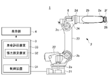
- the robot system 1 includes a robot 2, a robot control device 3 for controlling the robot 2, and a display unit 4 connected to the robot control device 3.
- the robot 2 of the present embodiment is a vertical articulated robot provided with a plurality of movable parts.
- the robot 2 is a 6-axis vertical articulated robot having 6 axes of J1 axis 2a, J2 axis 2b, J3 axis 2c, J4 axis 2d, J5 axis 2e, and J6 axis 2f as movable parts.
- the robot 2 is attached to a base portion 21 installed on a floor surface or the like, a first swivel portion 22 provided on the base portion 21, a first arm portion 23 attached to the first swivel portion 22, and a first arm portion 23. It has a second swivel portion 24, a second arm portion 25 attached to the second swivel portion 24, and a wrist unit 26 attached to the tip of the second arm portion 25.
- the first turning portion 22 can rotate horizontally with respect to the base portion 21 by the J1 axis 2a.
- the first arm portion 23 can swing in the front-rear direction with respect to the first turning portion 22 by the J2 axis 2b.
- the second turning portion 24 can swing in the vertical direction with respect to the first arm portion 23 by the J3 axis 2c.
- the second arm portion 25 is rotatable about the longitudinal axis of the second arm portion 25 by the J4 axis 2d with respect to the second turning portion 24.
- the wrist unit 26 can swing up and down with respect to the second arm portion 25 by the J5 axis 2e, and can rotate around an axis intersecting the J5 axis 2e by the J6 axis 2f.
- the robot 2 is provided with a motor for driving the J1 axis 2a to the J6 axis 2f (not shown in FIG. 1) and a transmission mechanism for transmitting the power of the motor to each axis for each axis.
- FIG. 2 shows the inside of the second arm portion 25 of the robot 2. Inside the second arm portion 25, a J5 axis motor 5 that swings the wrist unit 26 around the J5 axis 2e is arranged. The power of the J5 axis motor 5 is transmitted to the J5 axis 2e via the transmission mechanism 6.
- the transmission mechanism 6 includes a first pulley 61 attached to the output shaft 5a of the J5 axis motor 5, a second pulley 62 attached to the J5 axis 2e, and a belt 63 bridged to the first pulley 61 and the second pulley 62. , A speed reducer 64 for decelerating the rotation of the second pulley 62.
- the output shaft 5a and the J5 shaft 2e are rotatably supported by bearings (not shown), respectively.
- the bearing (not shown) in these transmission mechanisms 6 is a member whose life changes according to a change in belt tension.
- a J6 axis motor 7 for driving the J6 axis 2f is also provided inside the second arm portion 25 in the vicinity of the J5 axis motor 5.
- the power of the J6 axis motor 7 is transmitted to the J6 axis 2f via a transmission mechanism (not shown).
- the second turning portion 24 is provided with a J4 axis motor 8 for driving the J4 axis 2d.
- the life of the transmission mechanism provided in the robot 2 is affected by the temperature of the component where the transmission mechanism is arranged.
- the life of the transmission mechanism 6 is affected by the temperature of the second arm portion 25 itself. That is, when the temperature of the second arm portion 25 rises due to the driving of the robot 2, the members (mainly metals such as castings) constituting the second arm portion 25 expand, and the J5-axis motor 5 shown in FIG. 2 The distance L between the output shaft 5a and the J5 shaft 2e becomes large. Along with this, the tension of the belt 63 increases, and the load applied to the first pulley 61 and the second pulley 62 increases. As a result, the life of the transmission mechanism 6 is shortened.
- the temperature rise of the constituent parts of the robot 2 can be generated not only by the heat generated by the motor arranged inside the constituent parts but also by the heat generated by other constituent parts arranged close to the constituent parts.
- the temperature rise of the second arm portion 25 causes the J6 axis 2f in addition to the heat generated by the J5 axis motor 5 arranged inside the second arm portion 25. It can also be generated by the heat generated by the driving J6 axis motor 7, and the frictional heat generated by the respective operations of the J4 axis 2d, the J5 axis 2e, and the J6 axis 2f, which are friction sites. Therefore, when estimating the tension of the belt 63 of the transmission mechanism 6 in the second arm portion 25 and the life of the transmission mechanism 6, it is necessary to consider the heat generated by these constituent parts arranged close to the belt 63. There is.
- the robot control device 3 is electrically connected to the robot 2 and comprehensively controls the operation of the robot 2.
- the robot control device 3 includes a control device 31 that controls each part such as a motor of the robot 2, a tension estimation device 32 that estimates the tension of the belt 63 provided in the transmission mechanism 6 of the robot 2, and a transmission mechanism 6 of the robot 2. It has a life evaluation device 33 for estimating the life.
- the display unit 4 is composed of, for example, a liquid crystal display screen.
- the display unit 4 is connected to the robot control device 3 by wire or wirelessly, and displays various information transmitted from the robot control device 3 on the screen.
- the tension estimation device 32 includes a motor calorific value calculation unit 321, a friction calorific value calculation unit 322, an air-cooled heat dissipation amount calculation unit 323, and a belt tension estimation unit 324.
- the motor heat generation amount calculation unit 321 calculates the motor heat generation amount based on the state amount of the motor input from the control device 31. At least one of the motor current value and the motor rotation speed of at least one motor arranged close to the belt to be tension estimation is input to the motor calorific value calculation unit 321 from the control device 31. In the present embodiment, as shown in FIG. 3, both the motor current value and the motor rotation speed are configured to be input from the control device 31.
- the motor placed close to the belt is a motor placed close to the belt so that the heat generated by driving the motor affects the tension of the belt.
- the J5-axis motor 5 and the J6-axis motor 7 are arranged near the belt 63.
- the tension of the belt 63 is affected by the heat generated by the J5-axis motor 5 and the J6-axis motor 7. Therefore, when estimating the tension of the belt 63 of the second arm portion 25, at least one of the motor current value and the motor rotation speed of the J5-axis motor 5 and the J6-axis motor 7 is input to the motor calorific value calculation unit 321. Will be done.
- the motor calorific value calculation unit 321 calculates the motor calorific value of the motor that drives the shaft to be calculated by the following equation (1) based on at least one of the input motor current value and the motor rotation speed. do.
- M n a ⁇ C n + b ⁇ V n + c ⁇ (V n ) 2 ... (1)
- M n Motor calorific value of Jn-axis motor [W] Cn ; Motor current value of Jn-axis motor [Ap] V n ; Motor rotation speed of Jn-axis motor [rpm] a, b, c; Coefficient
- the friction calorific value calculation unit 322 is set to at least one of the friction coefficients of the motor current value input from the control device 31, the motor rotation speed, and the friction coefficient of at least one shaft arranged close to the belt to be estimated for tension. Based on this, the frictional calorific value in the transmission mechanism is calculated.
- the motor current value and the motor rotation speed input to the friction calorific value calculation unit 322 are the motor current value and the motor rotation speed of at least one motor arranged in the vicinity of the belt to be the tension estimation target.
- the second arm portion 25 of the robot 2 shown in FIG. 2 it is the motor current value and the motor rotation speed of the J5-axis motor 5 and the J6-axis motor 7.
- the shaft is a portion where frictional heat is generated by driving.
- the frictional heat generated by driving the J4 axis 2d, the J5 axis 2e, and the J6 axis 2f may affect the tension of the belt 63. ..
- the friction calorific value calculation unit 322 calculates the friction calorific value in the transmission mechanism by the following equation (2) based on at least one of these motor current values, motor rotation speed, and friction coefficient.
- F n k 1 ⁇ C n V n + k 2 ⁇ V n + k 3 ⁇ (V n ) 2 ...
- the air-cooled heat radiation amount calculation unit 323 calculates the air-cooled heat radiation amount of the transmission mechanism based on the moving speed of the transmission mechanism.
- the air-cooled heat radiation amount is the heat radiation amount generated because the arm portion moves in the air due to the operation of the robot 2 and a relative speed is generated between the arm portion and the surrounding air.
- the amount of air-cooled heat radiation is proportional to the moving speed rate (V wcp ) of the transmission mechanism.
- the moving speed rate (V wcp ) of the transmission mechanism is calculated by the following equation (3).
- the speed of the arm portion is uniquely determined from the minute angle change amount of the J1 axis 2a to the J6 axis 2f.
- V wcp (speed at a specific position of the arm) / (maximum speed at a specific position of the arm) ... (3)
- the belt tension estimation unit 324 has a motor heat generation amount calculated by the motor heat generation amount calculation unit 321, a friction heat generation amount calculated by the friction heat generation amount calculation unit 322, and an air-cooled heat dissipation amount calculated by the air-cooled heat dissipation amount calculation unit 323. Based on the above, the tension of the belt in the transmission mechanism is calculated by the belt tension estimation formula shown in the following formula (4).
- T 0 and a, b, c, and d are model-specific coefficients that do not depend on the movement of the robot 2.
- the tension of the belt 63 of the transmission mechanism 6 of the second arm portion 25 is close to the motor calorific value of the J5-axis motor 5 and the J6-axis motor 7 arranged close to the belt 63 and the belt 63. It is affected by the frictional heat generation amount of the J4 axis 2d, the J5 axis 2e, and the J6 axis 2f, which are the axes arranged in the above direction.
- the motor calorific value M is the motor calorific value of the J5 axis motor 5 and the J6 axis motor 7, and the friction calorific value F is the J4 axis 2d, the J5 axis 2e and The frictional calorific value of the J6 shaft 2f is used.
- M 5 25 [W]
- M 6 22.5 [W].
- the friction coefficient k a4 with respect to the average of the motor current speed is 0.005
- the friction coefficient k b4 with respect to the average motor rotation speed is 0.10
- the friction coefficient k c4 with respect to the squared average of the motor rotation speed is 0.
- the friction calorific value F4 450 [W] of the J4 axis 2d.
- the friction coefficient k a5 with respect to the average of the motor current speed is 0.0001
- the friction coefficient k b5 with respect to the average motor rotation speed is 0.02
- the friction coefficient k c5 with respect to the average of the motor rotation speed squared is
- the friction coefficient k a6 with respect to the average of the motor current speed is 0.001
- the friction coefficient k b6 with respect to the average motor rotation speed is 0.08
- the friction coefficient k c6 with respect to the squared average of the motor rotation speed is 0.00001.
- the frictional calorific value F 6 153.8 [W] of the J6 axis 2f.
- the belt tension estimation formula of the formula (4) at least one of the initial tension T 0 of the belt and the coefficients a, b, c, and d is a parameter that changes depending on the room temperature.
- the belt tension can be estimated in consideration of the room temperature. Therefore, the tension of the belt can be estimated more accurately.
- the room temperature is input by the room temperature input unit 34 provided in the robot control device 3.
- the room temperature input by the room temperature input unit 34 may be performed manually by the operator, or the detection value of the temperature sensor (not shown) may be automatically input.
- the belt tension estimation formula of the formula (4) is a parameter that changes with time or the operating time of the robot 2. May be good. This is because the tension of the belt may decrease due to aging.
- the operating time of the robot 2 is input from the control device 31 to the belt tension estimation unit 324.
- T' T 0 -At ... (5) T'; Estimated belt tension including aging [N] T 0 ; Belt initial tension [N] A; Changes over time per 1h [N / h] t; operating time [h]
- the coefficient of the belt tension estimation formula of the formula (4) is corrected according to the time or operating time of the robot 2. Therefore, by including the parameter that changes depending on the time or operating time of the robot 2 in the belt tension estimation formula, the belt tension can be estimated in consideration of the time or operating time of the robot 2. Therefore, the tension of the belt can be estimated more accurately.
- the estimated tension of the belt due to the change with time may be simply calculated by the following formula (6).
- T' f (t) x T ... (6) T';
- the life evaluation device 33 includes the tension estimation device 32 described above, and further includes a life estimation unit 331, a remaining life calculation unit 332, and a replacement date calculation unit 333.
- the life estimation unit 331 estimates the life of the transmission mechanism based on the tension estimation value estimated by the belt tension estimation unit 324 of the tension estimation device 32. For example, in the case of the transmission mechanism 6 of the second arm portion 25 shown in FIG. 2, the life of the transmission mechanism 6 is estimated from the tension estimation value of the belt 63 estimated by the tension estimation device 32.
- the life of the transmission mechanism is said to be proportional to the cube of the tension of the belt.
- the life estimation unit 331 estimates the life of the transmission mechanism by the following equation (7) based on the tension estimation value of the belt obtained by the tension estimation device 32. For example, in the case of a transmission mechanism in which the life reaches 100 [%] when operated for 10000 [h] when the belt tension is 250 [N], the belt tension estimated value is 200 [N] and 5000 [h]. ]
- the life progress rate (life estimation value) of the transmission mechanism when operated is 26 [%] from the following formula (7). According to this, the life estimation unit 331 can estimate that the life of the current transmission mechanism has reached 26%.
- S g Estimated life of transmission mechanism [%] T; Estimated belt tension [N] t; operating time [h]
- the remaining life calculation unit 332 calculates the remaining life of the transmission mechanism based on the life estimation value of the transmission mechanism calculated by the life estimation unit 331. According to this, the life evaluation device 33 can notify the operator how long the remaining life of the transmission mechanism is. Specifically, the remaining life calculation unit 332 calculates the remaining life Sr of the transmission mechanism by the following equation (8) based on the life estimation value of the transmission mechanism calculated by the life estimation unit 331.
- S r 100-S g [%] ⁇ ⁇ ⁇ (8) S r ; Remaining life [%] S g ; Estimated life of transmission mechanism [%]
- the remaining life information calculated by the remaining life calculation unit 332 is sent to the display unit 4 and displayed on the display unit 4.
- the display unit 4 may display the remaining life value itself sent from the remaining life calculation unit 332, or display a warning when the calculated remaining life value becomes smaller than a preset threshold value. You may do so.
- the remaining life calculation unit 332 may have a function of determining whether or not the value of the remaining life is smaller than the threshold value, or the display unit 4 may have a function.
- the replacement date calculation unit 333 calculates the estimated replacement date of the transmission mechanism based on the life estimation value of the transmission mechanism calculated by the life estimation unit 331. According to this, the life evaluation device 33 can notify the operator of the guideline of the replacement date of the transmission mechanism before the transmission mechanism is broken. Specifically, the replacement date calculation unit 333 calculates the replacement date (recommended replacement date) of the transmission mechanism by the following equation (9) based on the life estimation value of the transmission mechanism calculated by the life estimation unit 331. The exchange date information calculated by the exchange date calculation unit 333 is sent to the display unit 4 and displayed on the display unit 4. However, the method of calculating the exchange date of the transmission mechanism is not limited to the following equation (9), and any other approximate calculation method may be adopted.
- the life evaluation device 33 can accurately evaluate the life of the transmission mechanism from the tension estimation value of the belt obtained by the tension estimation device 32. Since the life evaluation device 33 evaluates the life of the transmission mechanism based on the tension of the belt obtained by the tension estimation device 32, it evaluates the life with high accuracy in consideration of the load applied to the transmission mechanism due to the increase in the tension of the belt. Can be done.
- the belt tension estimation unit 324 of the tension estimation device 32 generates motor heat by machine learning using the motor heat generation amount calculated by the motor heat generation amount calculation unit 321 and the friction heat generation amount calculated by the friction heat generation amount calculation unit 322.
- a trained model for estimating belt tension from the amount and frictional calorific value may be generated. According to this, it is possible to accurately estimate the tension of the belt by using the trained model based on the data of the motor calorific value and the friction calorific value of various patterns.
- the tension estimation device 32 may include a storage unit 325 that stores the trained model generated by machine learning, as shown in FIG.
- the belt tension estimation unit 324 can estimate the belt tension using the learned model stored in the storage unit 325 based on the motor heat generation amount and the friction heat generation amount. According to this, since the tension of the belt using the trained model stored in the storage unit 325 is estimated, the tension of the belt can be estimated more accurately without generating the trained model from the beginning. can.
- Machine learning may be supervised learning using supervised learning using motor calorific value and friction calorific value as input data and teacher data associated with each other using the measured value of belt tension as a label. According to this, by using the measured value of the belt tension as the correct answer, the belt tension with respect to the input data can be estimated more accurately. As shown in FIG. 4, the measured value of the belt tension is manually input by the operator by the measured value input unit 35 provided in the robot control device 3.
- the belt tension estimation unit 324 of the tension estimation device 32 may estimate the belt tension from the temperature of the transmission mechanism instead of calculating the belt tension estimation value using the above equation (4).
- the tension estimation device 32 in this case can include a transmission mechanism temperature estimation unit 326.
- the transmission mechanism temperature estimation unit 326 has a motor heat generation amount calculated by the motor heat generation amount calculation unit 321, a friction heat generation amount calculated by the friction heat generation amount calculation unit 322, and an air cooling release calculated by the air cooling heat dissipation amount calculation unit 323.
- the temperature of the transmission mechanism is estimated by the following equation (10) based on the amount of heat.
- T p Estimated temperature of the transmission mechanism Tr; Room temperature F n ; Friction calorific value of the shaft driven by the Jn shaft motor [W] M n ; Motor calorific value of Jn-axis motor [W] W 1 ; Air-cooled heat dissipation amount W 2 ; Heat generation amount of other sources a, b, c, d, e, f, g; Coefficient m; Integer of any combination
- the belt tension estimation unit 324 estimates the belt tension from the graph of FIG. 6 based on the temperature of the transmission mechanism estimated by the transmission mechanism temperature estimation unit 326. According to this, the tension of the belt can be easily estimated.
- the tension estimation device 32 including the transmission mechanism temperature estimation unit 326 may also have a configuration for generating a trained model by machine learning, similar to the tension estimation device 32 shown in FIG.
- the motor calorific value calculation unit 321 calculates the motor calorific value based on the motor current value and the motor rotation speed.
- the motor calorific value calculation unit 321 may more simply calculate the motor calorific value based on at least one of the motor current value and the motor rotation speed.
- the friction calorific value calculation unit 322 calculates the friction calorific value in the transmission mechanism 6 based on the motor current value, the motor rotation speed, and the friction coefficient of the transmission mechanism 6. However, even if the friction calorific value calculation unit 322 simply calculates the friction calorific value in the transmission mechanism 6 based on at least one of the motor current value, the motor rotation speed, and the friction coefficient of the transmission mechanism 6. good.
- the tension estimation device 32 may be a simple device that does not have the air-cooled heat dissipation amount calculation unit 323. Further, the belt tension estimation unit 324 may simply estimate the belt tension based on the two calorific values of the motor calorific value and the friction calorific value.
- Robot system Robot (machine) 2a J1 axis (moving part) 2b J2 axis (moving part) 2c J3 axis (moving part) 2d J4 axis (moving part) 2e J5 axis (moving part) 2f J6 axis (moving part) 31
- Control device 32
- Tension estimation device 321 Motor calorific value calculation unit 322 Friction calorific value calculation unit 324
- Belt tension estimation unit 323
- Storage unit 326 Transmission mechanism temperature estimation unit 33 Life evaluation device 331 Lifespan estimation unit 332 Remaining life Calculation unit 333
Landscapes
- Engineering & Computer Science (AREA)
- Robotics (AREA)
- Mechanical Engineering (AREA)
- Physics & Mathematics (AREA)
- General Physics & Mathematics (AREA)
- Devices For Conveying Motion By Means Of Endless Flexible Members (AREA)
- Manipulator (AREA)
- Testing Of Devices, Machine Parts, Or Other Structures Thereof (AREA)
Priority Applications (4)
| Application Number | Priority Date | Filing Date | Title |
|---|---|---|---|
| JP2022565302A JP7538246B2 (ja) | 2020-11-26 | 2021-11-19 | 張力推定装置、寿命評価装置及びロボットシステム |
| CN202180077650.4A CN116457165B (zh) | 2020-11-26 | 2021-11-19 | 张力估计装置、寿命评价装置以及机器人系统 |
| US18/251,825 US20230405807A1 (en) | 2020-11-26 | 2021-11-19 | Tension estimation device, life evaluation device, and robot system |
| DE112021004859.7T DE112021004859T5 (de) | 2020-11-26 | 2021-11-19 | Spannungsschätzungsvorrichtung, Lebensdauerbewertungsvorrichtung und Robotersystem |
Applications Claiming Priority (2)
| Application Number | Priority Date | Filing Date | Title |
|---|---|---|---|
| JP2020-196020 | 2020-11-26 | ||
| JP2020196020 | 2020-11-26 |
Publications (1)
| Publication Number | Publication Date |
|---|---|
| WO2022113901A1 true WO2022113901A1 (ja) | 2022-06-02 |
Family
ID=81754278
Family Applications (1)
| Application Number | Title | Priority Date | Filing Date |
|---|---|---|---|
| PCT/JP2021/042594 Ceased WO2022113901A1 (ja) | 2020-11-26 | 2021-11-19 | 張力推定装置、寿命評価装置及びロボットシステム |
Country Status (6)
| Country | Link |
|---|---|
| US (1) | US20230405807A1 (https=) |
| JP (1) | JP7538246B2 (https=) |
| CN (1) | CN116457165B (https=) |
| DE (1) | DE112021004859T5 (https=) |
| TW (1) | TWI891941B (https=) |
| WO (1) | WO2022113901A1 (https=) |
Cited By (1)
| Publication number | Priority date | Publication date | Assignee | Title |
|---|---|---|---|---|
| WO2025069127A1 (ja) * | 2023-09-25 | 2025-04-03 | 三菱電機株式会社 | 異常診断装置及び異常診断方法 |
Families Citing this family (1)
| Publication number | Priority date | Publication date | Assignee | Title |
|---|---|---|---|---|
| JP2024049638A (ja) * | 2022-09-29 | 2024-04-10 | セイコーエプソン株式会社 | 水平多関節ロボット |
Citations (5)
| Publication number | Priority date | Publication date | Assignee | Title |
|---|---|---|---|---|
| JP2004020388A (ja) * | 2002-06-17 | 2004-01-22 | Mitsubishi Electric Corp | 寿命評価装置 |
| JP2005156394A (ja) * | 2003-11-27 | 2005-06-16 | Mitsuboshi Belting Ltd | 伝動ベルトの振動解析方法及び装置、並びにプログラム |
| JP2015093360A (ja) * | 2013-11-13 | 2015-05-18 | キヤノン株式会社 | 駆動装置、ロボット装置、駆動装置の制御方法、プログラム及び記録媒体 |
| US9205560B1 (en) * | 2013-06-24 | 2015-12-08 | Redwood Robotics, Inc. | System and method for failure detection of a robot actuator |
| JP6694016B2 (ja) * | 2018-07-10 | 2020-05-13 | ファナック株式会社 | 寿命評価装置およびロボットシステム |
Family Cites Families (8)
| Publication number | Priority date | Publication date | Assignee | Title |
|---|---|---|---|---|
| FR2827042B1 (fr) * | 2001-07-06 | 2003-10-03 | Renault | Procede d'evaluation de la duree de vie restante d'une courroie de transmission, et son dispositif de mise en oeuvre |
| JP4087435B2 (ja) * | 2007-07-30 | 2008-05-21 | 三菱電機株式会社 | 寿命評価装置 |
| JP2014092198A (ja) * | 2012-11-01 | 2014-05-19 | C I Kasei Co Ltd | ベルト交換時期推定システム |
| US9347372B2 (en) * | 2014-09-13 | 2016-05-24 | GM Global Technology Operations LLC | Method for determining belt life |
| KR101924724B1 (ko) * | 2017-06-20 | 2018-12-03 | 한국광기술원 | 장력 조절 기능을 가지는 벨트 동력 전달 장치 및 그 제어 방법 |
| JP6592061B2 (ja) * | 2017-11-02 | 2019-10-16 | ファナック株式会社 | ベルトの交換判定装置および交換判定方法 |
| JP7063750B2 (ja) | 2018-07-10 | 2022-05-09 | ファナック株式会社 | 温度推定装置、寿命評価装置、およびロボットシステム |
| JP7103878B2 (ja) * | 2018-07-10 | 2022-07-20 | ファナック株式会社 | 温度推定装置及び寿命評価装置 |
-
2021
- 2021-11-18 TW TW110142974A patent/TWI891941B/zh active
- 2021-11-19 CN CN202180077650.4A patent/CN116457165B/zh active Active
- 2021-11-19 US US18/251,825 patent/US20230405807A1/en active Pending
- 2021-11-19 WO PCT/JP2021/042594 patent/WO2022113901A1/ja not_active Ceased
- 2021-11-19 DE DE112021004859.7T patent/DE112021004859T5/de active Pending
- 2021-11-19 JP JP2022565302A patent/JP7538246B2/ja active Active
Patent Citations (5)
| Publication number | Priority date | Publication date | Assignee | Title |
|---|---|---|---|---|
| JP2004020388A (ja) * | 2002-06-17 | 2004-01-22 | Mitsubishi Electric Corp | 寿命評価装置 |
| JP2005156394A (ja) * | 2003-11-27 | 2005-06-16 | Mitsuboshi Belting Ltd | 伝動ベルトの振動解析方法及び装置、並びにプログラム |
| US9205560B1 (en) * | 2013-06-24 | 2015-12-08 | Redwood Robotics, Inc. | System and method for failure detection of a robot actuator |
| JP2015093360A (ja) * | 2013-11-13 | 2015-05-18 | キヤノン株式会社 | 駆動装置、ロボット装置、駆動装置の制御方法、プログラム及び記録媒体 |
| JP6694016B2 (ja) * | 2018-07-10 | 2020-05-13 | ファナック株式会社 | 寿命評価装置およびロボットシステム |
Cited By (1)
| Publication number | Priority date | Publication date | Assignee | Title |
|---|---|---|---|---|
| WO2025069127A1 (ja) * | 2023-09-25 | 2025-04-03 | 三菱電機株式会社 | 異常診断装置及び異常診断方法 |
Also Published As
| Publication number | Publication date |
|---|---|
| CN116457165B (zh) | 2025-09-19 |
| JPWO2022113901A1 (https=) | 2022-06-02 |
| DE112021004859T5 (de) | 2023-07-20 |
| TWI891941B (zh) | 2025-08-01 |
| JP7538246B2 (ja) | 2024-08-21 |
| TW202221296A (zh) | 2022-06-01 |
| US20230405807A1 (en) | 2023-12-21 |
| CN116457165A (zh) | 2023-07-18 |
Similar Documents
| Publication | Publication Date | Title |
|---|---|---|
| JP7063750B2 (ja) | 温度推定装置、寿命評価装置、およびロボットシステム | |
| US12049983B2 (en) | Life evaluating device and robot system | |
| JP7538246B2 (ja) | 張力推定装置、寿命評価装置及びロボットシステム | |
| JP6694016B2 (ja) | 寿命評価装置およびロボットシステム | |
| JP6881886B2 (ja) | 制御方法、ロボット装置、および駆動装置 | |
| US9329092B2 (en) | Method for determining a torque and an industrial robot | |
| US9302397B2 (en) | Prediction system | |
| JP5628953B2 (ja) | ガススプリングを備えた多関節ロボット、及びガススプリングの内圧を推定する方法 | |
| KR101344003B1 (ko) | 보수 정보 출력 장치 및 보수 정보 출력 시스템 | |
| JP5612150B2 (ja) | ガススプリングを備えた多関節ロボット、及びガススプリングの内圧を推定する方法 | |
| CN108778642B (zh) | 关节型机器人及其气弹簧的气体减少状态推定方法 | |
| CN113664824A (zh) | 机器人保养支持装置及方法 | |
| CN104582912A (zh) | 工业用机器人的集中监视装置、记录有集中监视程序的介质以及维护系统 | |
| JP2020110877A (ja) | ロボット診断方法、ロボット診断装置、制御プログラム、記録媒体、生産システム、および物品の製造方法 | |
| JP2015093360A (ja) | 駆動装置、ロボット装置、駆動装置の制御方法、プログラム及び記録媒体 | |
| EP3435183A1 (en) | Method for controlling a robot arm and robot system with a robot arm | |
| CN112276937B (zh) | 故障预测系统 | |
| JP2020008466A (ja) | 温度推定装置及び寿命評価装置 | |
| JP3978155B2 (ja) | 潤滑剤の劣化監視方法および装置 | |
| US20230400384A1 (en) | Abnormality detection device which detects abnormalities in power transmission mechanism for transmitting rotational force outputted by motor | |
| CN112729787A (zh) | 机械模拟装置和方法 | |
| JP2018152990A (ja) | サーボモータ制御装置、及び、サーボモータ制御システム | |
| WO2024218838A1 (ja) | ロボットシステムの演算装置 |
Legal Events
| Date | Code | Title | Description |
|---|---|---|---|
| 121 | Ep: the epo has been informed by wipo that ep was designated in this application |
Ref document number: 21897875 Country of ref document: EP Kind code of ref document: A1 |
|
| WWE | Wipo information: entry into national phase |
Ref document number: 18251825 Country of ref document: US |
|
| WWE | Wipo information: entry into national phase |
Ref document number: 202180077650.4 Country of ref document: CN |
|
| ENP | Entry into the national phase |
Ref document number: 2022565302 Country of ref document: JP Kind code of ref document: A |
|
| 122 | Ep: pct application non-entry in european phase |
Ref document number: 21897875 Country of ref document: EP Kind code of ref document: A1 |
|
| WWG | Wipo information: grant in national office |
Ref document number: 202180077650.4 Country of ref document: CN |