WO2022107688A1 - 画像生成装置、画像生成方法、およびプログラム - Google Patents
画像生成装置、画像生成方法、およびプログラム Download PDFInfo
- Publication number
- WO2022107688A1 WO2022107688A1 PCT/JP2021/041667 JP2021041667W WO2022107688A1 WO 2022107688 A1 WO2022107688 A1 WO 2022107688A1 JP 2021041667 W JP2021041667 W JP 2021041667W WO 2022107688 A1 WO2022107688 A1 WO 2022107688A1
- Authority
- WO
- WIPO (PCT)
- Prior art keywords
- player
- image
- mesh structure
- virtual object
- viewpoint
- Prior art date
- Legal status (The legal status is an assumption and is not a legal conclusion. Google has not performed a legal analysis and makes no representation as to the accuracy of the status listed.)
- Ceased
Links
Images


Classifications
-
- A—HUMAN NECESSITIES
- A63—SPORTS; GAMES; AMUSEMENTS
- A63F—CARD, BOARD, OR ROULETTE GAMES; INDOOR GAMES USING SMALL MOVING PLAYING BODIES; VIDEO GAMES; GAMES NOT OTHERWISE PROVIDED FOR
- A63F13/00—Video games, i.e. games using an electronically generated display having two or more dimensions
- A63F13/50—Controlling the output signals based on the game progress
- A63F13/53—Controlling the output signals based on the game progress involving additional visual information provided to the game scene, e.g. by overlay to simulate a head-up display [HUD] or displaying a laser sight in a shooting game
-
- A—HUMAN NECESSITIES
- A63—SPORTS; GAMES; AMUSEMENTS
- A63F—CARD, BOARD, OR ROULETTE GAMES; INDOOR GAMES USING SMALL MOVING PLAYING BODIES; VIDEO GAMES; GAMES NOT OTHERWISE PROVIDED FOR
- A63F13/00—Video games, i.e. games using an electronically generated display having two or more dimensions
- A63F13/20—Input arrangements for video game devices
- A63F13/21—Input arrangements for video game devices characterised by their sensors, purposes or types
- A63F13/213—Input arrangements for video game devices characterised by their sensors, purposes or types comprising photodetecting means, e.g. cameras, photodiodes or infrared cells
-
- A—HUMAN NECESSITIES
- A63—SPORTS; GAMES; AMUSEMENTS
- A63F—CARD, BOARD, OR ROULETTE GAMES; INDOOR GAMES USING SMALL MOVING PLAYING BODIES; VIDEO GAMES; GAMES NOT OTHERWISE PROVIDED FOR
- A63F13/00—Video games, i.e. games using an electronically generated display having two or more dimensions
- A63F13/50—Controlling the output signals based on the game progress
- A63F13/52—Controlling the output signals based on the game progress involving aspects of the displayed game scene
- A63F13/525—Changing parameters of virtual cameras
-
- A—HUMAN NECESSITIES
- A63—SPORTS; GAMES; AMUSEMENTS
- A63F—CARD, BOARD, OR ROULETTE GAMES; INDOOR GAMES USING SMALL MOVING PLAYING BODIES; VIDEO GAMES; GAMES NOT OTHERWISE PROVIDED FOR
- A63F13/00—Video games, i.e. games using an electronically generated display having two or more dimensions
- A63F13/60—Generating or modifying game content before or while executing the game program, e.g. authoring tools specially adapted for game development or game-integrated level editor
- A63F13/65—Generating or modifying game content before or while executing the game program, e.g. authoring tools specially adapted for game development or game-integrated level editor automatically by game devices or servers from real world data, e.g. measurement in live racing competition
- A63F13/655—Generating or modifying game content before or while executing the game program, e.g. authoring tools specially adapted for game development or game-integrated level editor automatically by game devices or servers from real world data, e.g. measurement in live racing competition by importing photos, e.g. of the player
-
- A—HUMAN NECESSITIES
- A63—SPORTS; GAMES; AMUSEMENTS
- A63F—CARD, BOARD, OR ROULETTE GAMES; INDOOR GAMES USING SMALL MOVING PLAYING BODIES; VIDEO GAMES; GAMES NOT OTHERWISE PROVIDED FOR
- A63F13/00—Video games, i.e. games using an electronically generated display having two or more dimensions
- A63F13/85—Providing additional services to players
- A63F13/86—Watching games played by other players
-
- G—PHYSICS
- G06—COMPUTING OR CALCULATING; COUNTING
- G06F—ELECTRIC DIGITAL DATA PROCESSING
- G06F3/00—Input arrangements for transferring data to be processed into a form capable of being handled by the computer; Output arrangements for transferring data from processing unit to output unit, e.g. interface arrangements
- G06F3/01—Input arrangements or combined input and output arrangements for interaction between user and computer
- G06F3/011—Arrangements for interaction with the human body, e.g. for user immersion in virtual reality
-
- G—PHYSICS
- G06—COMPUTING OR CALCULATING; COUNTING
- G06T—IMAGE DATA PROCESSING OR GENERATION, IN GENERAL
- G06T15/00—Three-dimensional [3D] image rendering
- G06T15/10—Geometric effects
- G06T15/20—Perspective computation
-
- G—PHYSICS
- G06—COMPUTING OR CALCULATING; COUNTING
- G06T—IMAGE DATA PROCESSING OR GENERATION, IN GENERAL
- G06T15/00—Three-dimensional [3D] image rendering
- G06T15/10—Geometric effects
- G06T15/40—Hidden part removal
-
- G—PHYSICS
- G06—COMPUTING OR CALCULATING; COUNTING
- G06T—IMAGE DATA PROCESSING OR GENERATION, IN GENERAL
- G06T15/00—Three-dimensional [3D] image rendering
- G06T15/50—Lighting effects
-
- G—PHYSICS
- G06—COMPUTING OR CALCULATING; COUNTING
- G06T—IMAGE DATA PROCESSING OR GENERATION, IN GENERAL
- G06T17/00—Three-dimensional [3D] modelling for computer graphics
- G06T17/20—Finite element generation, e.g. wire-frame surface description, tesselation
-
- G—PHYSICS
- G06—COMPUTING OR CALCULATING; COUNTING
- G06T—IMAGE DATA PROCESSING OR GENERATION, IN GENERAL
- G06T7/00—Image analysis
- G06T7/70—Determining position or orientation of objects or cameras
-
- G—PHYSICS
- G06—COMPUTING OR CALCULATING; COUNTING
- G06V—IMAGE OR VIDEO RECOGNITION OR UNDERSTANDING
- G06V10/00—Arrangements for image or video recognition or understanding
- G06V10/20—Image preprocessing
- G06V10/34—Smoothing or thinning of the pattern; Morphological operations; Skeletonisation
-
- G—PHYSICS
- G06—COMPUTING OR CALCULATING; COUNTING
- G06V—IMAGE OR VIDEO RECOGNITION OR UNDERSTANDING
- G06V20/00—Scenes; Scene-specific elements
- G06V20/20—Scenes; Scene-specific elements in augmented reality scenes
-
- G—PHYSICS
- G06—COMPUTING OR CALCULATING; COUNTING
- G06V—IMAGE OR VIDEO RECOGNITION OR UNDERSTANDING
- G06V20/00—Scenes; Scene-specific elements
- G06V20/60—Type of objects
- G06V20/64—Three-dimensional [3D] objects
-
- G—PHYSICS
- G06—COMPUTING OR CALCULATING; COUNTING
- G06V—IMAGE OR VIDEO RECOGNITION OR UNDERSTANDING
- G06V40/00—Recognition of biometric, human-related or animal-related patterns in image or video data
- G06V40/10—Human or animal bodies, e.g. vehicle occupants or pedestrians; Body parts, e.g. hands
- G06V40/103—Static body considered as a whole, e.g. static pedestrian or occupant recognition
-
- G—PHYSICS
- G06—COMPUTING OR CALCULATING; COUNTING
- G06V—IMAGE OR VIDEO RECOGNITION OR UNDERSTANDING
- G06V40/00—Recognition of biometric, human-related or animal-related patterns in image or video data
- G06V40/20—Movements or behaviour, e.g. gesture recognition
- G06V40/23—Recognition of whole body movements, e.g. for sport training
-
- G—PHYSICS
- G06—COMPUTING OR CALCULATING; COUNTING
- G06T—IMAGE DATA PROCESSING OR GENERATION, IN GENERAL
- G06T2207/00—Indexing scheme for image analysis or image enhancement
- G06T2207/30—Subject of image; Context of image processing
- G06T2207/30196—Human being; Person
- G06T2207/30201—Face
Definitions
- This disclosure relates to an image generator, an image generation method, and a program.
- a head-mounted display (HMD) connected to a game machine is attached to the head, and while watching the screen displayed on the HMD, the game is played by operating a controller or the like.
- the HMD When the HMD is attached, the user does not see anything other than the image displayed on the HMD, so that the user feels more immersed in the image world and has the effect of further enhancing the entertainment of the game.
- the HMD displays a virtual reality (VR) image and the user wearing the HMD rotates his / her head to display the virtual space around the entire area that can be seen 360 degrees, the feeling of immersion in the image is further enhanced. And the operability of applications such as games will also improve.
- VR virtual reality
- video transmission type HMD that can capture images of the outside world with the camera mounted on the HMD and display them on the display panel.
- video transmission type HMD it is also possible to generate and display an augmented reality (AR) image by superimposing an object of a virtual world generated by computer graphics (CG) on an image of the outside world taken by a camera. ..
- AR augmented reality
- CG computer graphics
- the image of augmented reality is an extension of the real world with virtual objects, and the user experiences the virtual world while being aware of the connection with the real world. Can be done.
- the virtual object that should be in the back may overwrite a part of the player's body that should be in the foreground. Therefore, the depth may not be accurately expressed. As a result, there is no sense of unity between the player's body and the virtual object, and the image becomes unnatural.
- one object of the present disclosure is an image generator, an image capable of providing an image in which the depth of a player's body and a virtual object superimposed on the player's body are more accurately expressed.
- the purpose is to provide a generation method and a program.
- the image generation device of a certain aspect of the present disclosure includes a player recognition unit that recognizes the player's body, a viewpoint acquisition unit that acquires viewpoint information including a viewpoint position and a viewpoint direction, and the recognition result.
- a mesh generator that generates a player's mesh structure that reflects the player's body skeleton, and the player's mesh structure and virtual object when viewed from the viewpoint position in the viewpoint information in the viewpoint direction. Is included, and an image generation unit that generates an image by superimposing the rendered virtual object on the mesh structure of the rendered player.
- the skeleton of the player's body is reflected based on the step of recognizing the player's body, the step of acquiring the viewpoint information regarding the viewpoint position and the viewpoint direction, and the recognition result.
- the step of generating the mesh structure of the player and the mesh structure and the virtual object of the player when viewed from the viewpoint position in the viewpoint information to the viewpoint direction are rendered, and the mesh structure of the rendered player is described. Includes steps to generate an image by superimposing a rendered virtual object.
- the program of yet another aspect of the present disclosure reflects the skeleton of the player's body based on the step of recognizing the player's body, the step of acquiring the viewpoint information regarding the viewpoint position and the viewpoint direction, and the recognition result.
- the step of generating the mesh structure of the player and the mesh structure and the virtual object of the player when viewed from the viewpoint position in the viewpoint information in the viewpoint direction are rendered, and the rendering is performed on the mesh structure of the rendered player. It is a program for making a computer execute a step of generating an image by superimposing a virtual object created on the computer.
- FIG. 1st Embodiment It is an overall schematic diagram of the image generation system of 1st Embodiment. It is a figure which shows the use example of an embodiment by a user. It is a block diagram of the image generation apparatus of 1st Embodiment. It is a figure which illustrates the skeleton. It is a figure which illustrates the mesh structure. It is a figure which shows the example which superimposes virtual object on the mesh structure of a player. It is a figure which shows the example of the photographed image. It is a figure which shows the example of the image which superposed the virtual object on the photographed image of FIG. It is a figure which shows the example which expressed the occlusion by the conventional method.
- FIG. 10A It is a figure which shows the example which expressed the occlusion by the method of 1st Embodiment. It is a block diagram of the image generation apparatus of 2nd Embodiment. The mesh structure of the player on which the captured image in the real space is superimposed is shown. It is a figure which shows the example which superposed the virtual object of the leg part of the mechanical structure on the leg part in the mesh structure of the player of FIG. 10A. It is a figure which shows the example of the process which distorts a space. It is a figure which shows the example which superposed the virtual object after the processing of FIG. 10C.
- FIG. 1 is an overall schematic view of the image generation system of the first embodiment.
- the image generation system 10 of FIG. 1 includes an image generation device 100.
- An example of the image generation device 100 is a game machine.
- the image generation device 100 is connected to a head-mounted display (HMD) 15, a camera 19, and an image providing device 21.
- HMD head-mounted display
- the number of HMDs 15 connected to the image generator 100 is not limited to the example of FIG.
- the image generation device 100 includes a control unit 11, a storage unit 12, and an interface unit 13.
- the control unit 11 includes a processor and executes a program stored in the storage unit 12 to execute various information processing.
- the storage unit 12 includes a memory device such as a RAM, and stores a program executed by the control unit 11 and data processed by the program.
- the interface unit 13 is an interface for data communication between the HMD 15, the camera 19, and the image providing device 21.
- the image generation device 100 is connected to the HMD 15, the camera 19, and the image providing device 21 by wire or wirelessly via the interface unit 13.
- the interface unit 13 includes a multimedia interface such as HDMI (registered trademark) (High-Definition Multimedia Interface), which is a standard for a communication interface for transmitting video and audio as a digital signal.
- HDMI registered trademark
- High-Definition Multimedia Interface High-Definition Multimedia Interface
- the HMD 15 is a viewing device that is attached to the user's head to watch still images and moving images displayed on the display, and to listen to audio and music output from headphones.
- the HMD 15 is provided with a gyro sensor and an acceleration sensor.
- the HMD15 uses these sensors to measure the position information of the head of the user wearing the HMD15 and the rotation angle and inclination of the head.
- a camera unit (not shown) is mounted on the HMD 15.
- the HMD 15 can use the camera unit to capture the outside world from the user's point of view while the user is wearing the HMD 15.
- the HMD 15 supplies the captured image to the image generation device 100.
- the HMD 15 displays an image generated by the image generation device 100 on the display based on the captured image.
- the camera 19 is installed so that the player of the game and objects such as floors and walls existing around the player can be photographed.
- the camera 19 supplies the captured image of the captured real space to the image generation device 100.
- the image providing device 21 is configured to receive the generated image from the image generating device 100 and to be able to provide the received image to the user.
- the image providing device 21 is configured to be able to display an image received from the image generating device 100. Further, the image providing device 21 is configured to be able to upload the received image as a content file to a moving image distribution server (not shown).
- the image generation device 100 may be connected to an input unit (not shown) for inputting operation information by the user.
- the image generation device 100 may have a communication interface for performing data communication with the outside via a communication network.
- FIG. 2 shows an example of use of this embodiment by a user.
- the user A is a player who plays a game and wears the HMD 15.
- the user B is a spectator who watches the play of the user A in the game, and is viewing the play image of the user A displayed by the image providing device 21.
- the camera 19 is arranged so as to shoot the user A from the front of the user A.
- the camera 19 is not limited to this arrangement, and the camera 19 may be arranged so as to shoot the user A from an arbitrary position such as directly beside, directly behind, or diagonally beside the user A.
- FIG. 3 is a configuration diagram of the image generator of the present embodiment.
- the image generation device 100 includes a player recognition unit 102, a captured image acquisition unit 101, a viewpoint acquisition unit 103, a skeleton generation unit 104, a mesh generation unit 105, an image generation unit 110, and an HDMI transmission / reception unit 106.
- the image generation unit 110 includes a rendering unit 111, a superimposing unit 112, a post process unit 113, and a distortion processing unit 114.
- FIG. 3 draws a block diagram focusing on functions, and these functional blocks can be realized in various forms by hardware only, software only, or a combination thereof (the same applies to FIG. 9 described later). ).
- this embodiment will be described by taking as an example the case of generating an image from a third-party viewpoint.
- a case where the user B generates an image of the viewpoint of the camera 19 in order to watch the game play of the user A will be described. It is assumed that the HMD 15 of the user A (player) and the image providing device 21 are supplied with an image of the same game play (game play of the user A) generated from each viewpoint.
- the captured image acquisition unit 101 acquires a captured image in the real space.
- the captured image in the real space of the present embodiment is acquired from the camera 19 via the HDMI transmission / reception unit 106.
- the captured image acquisition unit 101 supplies each acquired captured image to the player recognition unit 102, the viewpoint acquisition unit 103, and the superimposing unit 112.
- the player recognition unit 102 recognizes the player's body. Specifically, the player recognition unit 102 recognizes the position and posture of each body part of the player's body based on the position and posture of each body part of the user A in the photographed image acquired by the photographed image acquisition unit 101. do. For example, the player recognition unit 102 recognizes the player's body by estimating the position and posture of each part of the player using a trained machine learning model based on the captured image of the camera 19. For example, the player recognition unit 102 can recognize the player's body by using an open pose or the like. The player recognition unit 102 supplies the recognition result to the skeleton generation unit 104.
- the viewpoint acquisition unit 103 acquires viewpoint information including the viewpoint position and the line-of-sight direction of the camera 19 based on the captured image supplied from the camera 19 via the captured image acquisition unit 101.
- the viewpoint acquisition unit 103 supplies each acquired viewpoint information to the rendering unit 111.
- the viewpoint information of the camera 19 is an example of the viewpoint information of the spectator different from the viewpoint of the player.
- the skeleton generation unit 104 generates a skeleton of the player's body based on the recognition result of the player recognition unit 102. For example, the skeleton generation unit 104 estimates the position and posture of each part in the player's skeleton using a trained machine learning model based on the recognition result of the position and posture of each body part of the player's body. , Generate this skeleton. For example, the skeleton generation unit 104 can generate a skeleton by using an open pose or the like.
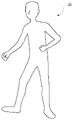
- FIG. 4A shows the skeleton generated by the skeleton generation unit 104.
- the example of FIG. 4A shows the case where the user A is viewed from the viewpoint (front view) of the camera 19 of FIG. 2 (the same applies to FIGS. 4B and 4C below).
- the skeleton 30 of FIG. 4A has a plurality of nodes 31 showing each end and each joint of the player's body.
- the skeleton 30 includes a player's head node 31a, chest node 31b, lumbar node 31c, shoulder node 31d, elbow node 31e, wrist node 31f, hand node 31g, knee node 31h, ankle node 31i and foot node. Including 31j.
- Adjacent nodes 31 are connected by bones 32.
- the skeleton generation unit 104 estimates the position and posture of each node 31 corresponding to the body part of the player with respect to the reference position and posture (for example, the initial position and posture at the start of the game). Generate skeleton 30.
- the estimated position and posture data of each node 31 is stored in the storage unit 12. Therefore, it is possible to accurately reflect the positional relationship in the depth direction for each part of the player's body.
- the skeleton generation unit 104 supplies the generated skeleton to the mesh generation unit 105.
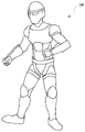
- the mesh generation unit 105 generates a player mesh structure that reflects the generated skeleton. For example, the mesh generation unit 105 generates the player's mesh structure 33 by modeling the skeleton with the mesh structure based on the shape of the player in the acquired image taken in the real space (see FIG. 4B). Modeling of the player's mesh structure is performed by a known method. The mesh generation unit 105 supplies the generated player mesh structure to the rendering unit 111.
- the rendering unit 111 renders the mesh structure of the player and the virtual object when viewed in the line-of-sight direction from the viewpoint position of the viewpoint information according to the viewpoint information of the camera 19. Specifically, the rendering unit 111 renders a virtual object, stores the color value in the pixel buffer 121, and sets the mesh structure of the player to, for example, white (RGB (255, 255, 255)) or gray (RGB (RGB (). It is rendered in 128, 128, 128)), rendered, and stored in the pixel buffer 121.
- the rendering unit 111 renders, as a virtual object for superimposing on the player's mesh structure, a virtual object that can be attached to at least a part of the player's mesh structure such as a player's avatar, costume, and decoration.
- the depth value (mesh depth value) of the player's mesh structure is written in the depth buffer (referred to as "mesh depth buffer") 122 for the player's mesh structure. If another virtual object exists in front of the player's mesh structure, the mesh depth value is not written to that pixel in the mesh depth buffer 122, or the mesh depth value is overwritten when the other virtual object is rendered. It will be erased. As a result, an area is generated only in the part where the player's mesh structure is drawn.
- the depth value (scene depth value) of the virtual object is written to the depth buffer (called “scene depth buffer”) 123 for virtual space rendering, and the context between the virtual objects is changed. It is judged. A specific depth value is not written in the scene depth buffer 123 for the pixel to which the virtual object is not drawn, and the scene depth value is infinite (undefined).
- the rendering unit 111 renders an expression related to light by a virtual object that will be superimposed on the mesh structure of the player.
- Expressions related to the light of a virtual object include, for example, shadows cast by the virtual object on the player's mesh structure, reflection of the virtual object on the player's mesh structure, translucency of the virtual object, and the player's mesh structure by a virtual light source.
- Shadow mapping can draw shadows and reflections using methods such as projecting a depth map from a light source onto a plane or ray tracing.
- the shadow or reflection of the virtual object on the user's mesh structure can be expressed. Since the user's mesh structure is rendered in solid white, it can be distinguished from the area where shadows and reflections are drawn. In this way, the image is given a representation of the light by the virtual object superimposed on the player's mesh structure.
- the rendering unit 111 supplies the rendered player's mesh structure and the rendered virtual object to the superimposing unit 112.
- the superimposing unit 112 superimposes the captured image on the mesh structure of the player rendered by the rendering unit 111. Specifically, the superimposing unit 112 superimposes the captured image on the region where the scene depth value is infinite and the region where the mesh depth value is written. The area written in the mesh depth value is superimposed on the captured image, leaving the color information of the shadow of the virtual object and the lighting expression (reflection, etc.). The superimposing unit 112 superimposes a virtual object on the mesh structure of the player on which the captured image is superposed.
- the superimposing unit 112 generates the player's avatar 34 by superimposing the virtual object of the avatar so as to be pasted on the mesh structure of the player.
- the whole body of the player is superimposed by the virtual object of the avatar, but the present invention is not limited to this, and a part of the body of the player may be superimposed by the virtual object.
- the mesh structure of the player on which the captured image is superimposed can be seen from the part other than the portion superimposed by the virtual object.
- the superimposing unit 112 supplies the superposed image to the post-process unit 113.
- the post-process unit 113 executes a process for expressing light by a virtual object on the superimposed image. Further, the post-process unit 113 executes a process for applying a drawing effect according to at least one of the position and the posture of the mesh structure of the player. This drawing effect includes, for example, motion blur according to a change in the position of the player's mesh structure, an aura that rises from the player's mesh structure according to the posture of the player's mesh structure, and the like. In addition to these, the post-process unit 113 may perform post-processes such as depth of field adjustment, tone mapping, and anti-aliasing to post-process the image so that it looks natural and smooth. The post-process unit 113 supplies the post-processed image to the distortion processing unit 114.
- the distortion processing unit 114 performs a process of distorting the post-processed image according to the distortion generated in the optical system of the camera 19.
- the distortion processing unit 114 supplies the image subjected to the distortion processing to the HDMI transmission / reception unit 106.
- the image generation unit 110 renders the player's mesh structure and virtual objects for each user A and B when viewed from the viewpoint position of each user A and B in the viewpoint direction.
- the image generation unit 110 generates an image by superimposing the rendered virtual object on the rendered mesh structure.
- the HDMI transmission / reception unit 106 transmits the image generated by the image generation unit 110 to the image providing device 21 according to HDMI.
- the image transmitted from the image generation device 100 is displayed on the display of the image providing device 21.
- the user B can see the image on which the virtual object is superimposed on the player.
- This image may be an AR image on which a video see-through image is superimposed as a background image of the player.
- this image may be a VR image on which a virtual object showing a virtual space is superimposed as a background image of the player.
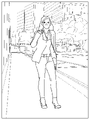
- FIG. 5 shows an example of a captured image captured by the camera 19.
- the photographed image of FIG. 5 is an image taken by the camera 19 of the user A who plays the game.
- the user A stands in front of the camera 19, and the face 400 of the user A is mainly photographed.
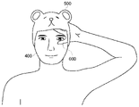
- FIG. 6 shows an example of an image in which a virtual object is superimposed on the captured image of FIG.
- the peripheral portion of the user A's face 400 is superimposed by the virtual object 500 of the bear's headgear.
- the user B can see an image in which the virtual object 500 of the bear's headgear is drawn around the face 400 of the user A through the image providing device 21.
- FIG. 7 is a diagram showing an example in which occlusion is expressed by a conventional method.
- FIG. 7 will be used to describe an example in which occlusion and depth are not properly represented.
- the example of FIG. 7 shows a user A trying to hide the face 400 with the hand 600.
- the hand 600 is reflected in the captured image at a position closer to the drawing than the face 400 of the user A.
- the virtual object 500 of the bear's headgear which should be on the back side in FIG. 7, may be superimposed on a part of the hand 600 of the user A, which should be on the front side in FIG. 7.
- FIG. 8 is a diagram showing an example in which occlusion is expressed by the method of this embodiment.
- the image generation device 100 of the present embodiment generates a player's mesh structure in which the skeleton of the player's body is reflected, and superimposes a virtual object on the player's mesh structure.
- the skeleton accurately reflects the positional relationship, including the depth of each part of the player's body. Therefore, according to the present embodiment, it is possible to more appropriately express the occlusion between the player's body and the virtual object superimposed on the player's mesh structure. As a result, the depth is appropriately expressed, a sense of unity is obtained between the player's body and the virtual object, and it is possible to provide a natural image.
- the viewpoint information includes the viewpoint position and the viewpoint direction of the spectator different from the player. According to this configuration, it is possible to provide an image to the spectator from the viewpoint of a third party (spectator) in which the depth of the player is appropriately expressed.
- the image generation unit 110 generates an image so as to give an expression related to light by a virtual object superimposed on the mesh structure of the player.
- the player's mesh structure generated based on the skeleton accurately reflects the positional relationship of each part of the player's body, so that the player's body more accurately reflects the expression of light by the virtual object. It becomes possible to provide an image.
- the image generation unit 110 generates an image so as to give a drawing effect corresponding to at least one of the position and the posture of the mesh structure of the player. According to this configuration, since the mesh structure of the player appropriately reflects the positional relationship of each part of the player's body, it is possible to more appropriately express drawing effects such as motion blur.
- the captured image is superimposed on the mesh structure of the player, and the virtual object is superimposed on the mesh structure of the player on which the captured image is superimposed. Therefore, according to this configuration, it is possible to more accurately represent the occlusion between the superimposed part of the virtual object in the player's body and the other parts of the player's body that reflect the actual appearance of the player. It becomes.
- FIG. 9 is a configuration diagram of the image generation device of the second embodiment.
- the image generation device 100 of the present embodiment further includes a depth acquisition unit 107 and a real space depth buffer 124.
- an AR image on which a video see-through image is superimposed is provided as a background image of the player.
- the depth acquisition unit 107 acquires depth information in the real space.
- the depth information of the real space of this embodiment is acquired from the camera 19.
- Depth information in the real space may be acquired using, for example, a depth sensor of a method such as an infrared pattern, Structured Light, or TOF (Time Of Flight).
- the depth acquisition unit 107 supplies the acquired depth information to the mesh generation unit 105.
- the mesh generation unit 105 of the present embodiment generates a mesh structure in the real space including the mesh structure of the player. Specifically, the mesh generation unit 105 generates the mesh structure of the real space by modeling the real space with the mesh structure based on the depth information of the real space. Modeling of the mesh structure in real space is performed by a known method.
- Real space mesh structures include real space walls, floors, ceilings, stationary objects, and the like.
- the rendering unit 111 renders the mesh structure in the real space in, for example, white (RGB (255, 255, 255)) and stores it in the pixel buffer 121.
- the depth value of the real object (referred to as "real space depth value") is written in the real space depth buffer 124 for real space rendering.
- the real space depth value is used to determine the context between real objects.
- the real space depth value is generated based on the depth information in the real space.
- FIG. 10A shows the mesh structure of the player on which the captured image in the real space is superimposed.
- a virtual object see FIG. 10B
- the leg portion of the mesh structure may protrude from the virtual object of the leg portion of the mechanical structure.
- the virtual objects of the legs of the mesh structure and the legs of the mechanical structure do not fit, and tend to be unnatural.
- the post-process unit 113 of the present embodiment when the mesh structure portion of the player on which the virtual object is superimposed protrudes from the superimposed virtual object, the superimposed portion does not protrude from the virtual object.
- a process is applied to distort the space around the skeleton in that part.
- a process of distorting this space is performed in at least one of the horizontal direction and the vertical direction.
- the legs of the player's mesh structure are moved along the bones 32 connecting the waist node 31c, the knee node 31h, the ankle node 31i, and the foot node 31j of the skeleton (see FIG. 4). Distort the surrounding space.
- a process of attracting pixels in the space around the bone 32 is performed. The closer it is to the bone, the greater the amount of pixel attraction. This makes it possible to make the legs of the player's mesh structure thinner.
- FIG. 10D The virtual object of the leg of the mechanical structure is superimposed on the leg of the mesh structure of the player after this processing. As shown in FIG. 10D, only the virtual object of the leg of the mechanical structure can be seen in the leg of the player.
- the virtual object can be fitted to the mesh structure of the player. Therefore, it is possible to suppress the occurrence of discomfort due to the difference in the mesh structure of the player and the size of the virtual object.
- the case where the mesh structure of the player protrudes from the superimposed virtual object is taken as an example, but the present invention is not limited to this.
- the space around it can be distorted to crush a part of the player's mesh structure. good.
- the player's avatar itself is set as a very heavy avatar (for example, a giant rock-like alien avatar), the space near the floor on which the avatar stands may be distorted. .. In this way, it is possible to make the player's mesh structure look smaller according to the characteristics of the virtual object.
- At least some of the functions of the image generator 100 may be implemented in the HMD 15 or the image providing device 21. Alternatively, at least a part of the functions of the image generation device 100 may be implemented in a server connected to the image generation device 100 via a network.
- the image generator 100 may be further connected to the server via a network.
- the server may provide the image generator 100 with an online application such as a game in which a plurality of users can participate via a network.
- the HMD 15 or the image providing device 21 may be connected to a computer or a mobile terminal instead of the image generating device 100.
- the user A is a player who plays the game
- the user B is a spectator who watches the play of the user A in the game
- both users A and B may be players playing the game.
- the player recognition unit 102 recognizes the player's body based on the captured image supplied from the camera 19, but the present invention is not limited to this.
- the player's body may be recognized by detecting the position and posture of the user's body part using a tracker.
- the HMD 15 may not be provided.
- the image of the image generation device 100 may be supplied to a separately provided display, and the user A may play the game based on the image displayed on the display.
- the user B also wears the HMD 15, supplies the captured image of the HMD 15 of the user B to the image generation device 100 instead of the captured image of the camera 19, and is generated by the image generation device 100 based on the viewpoint information of the HMD 15.
- the resulting image may be displayed on the HMD 15.
- the camera 19 and the image providing device 21 are separate bodies, but may be integrally configured.
- a personal computer or the like having a shooting function and a display function may be used.
- the captured image is superimposed on the virtual object of the player, but only the virtual object may be superimposed on the mesh structure without superimposing the captured image.
- processing such as depth of field adjustment, tone mapping, and antialiasing was illustrated as a post process, but it may also be called a post process including distortion processing, simple enlargement / reduction, and trapezoidal conversion.
- This disclosure relates to an image generator, an image generation method, and a program.
- 10 image generation system 15 HMD, 100 image generator, 101 captured image acquisition unit, 102 player recognition unit, 103 viewpoint acquisition unit, 104 skeleton generation unit, 105 mesh generation unit, 106 HDMI transmission / reception unit, 107 depth acquisition unit, 110 Image generation unit, 111 rendering unit, 112 superimposition unit, 113 post process unit, 114 distortion processing unit, 121 pixel buffer, 122 mesh depth buffer, 123 scene depth buffer, 124 real space depth buffer.
Landscapes
- Engineering & Computer Science (AREA)
- Multimedia (AREA)
- Physics & Mathematics (AREA)
- Theoretical Computer Science (AREA)
- General Physics & Mathematics (AREA)
- Human Computer Interaction (AREA)
- Computer Graphics (AREA)
- Geometry (AREA)
- General Engineering & Computer Science (AREA)
- Computer Vision & Pattern Recognition (AREA)
- Computing Systems (AREA)
- Software Systems (AREA)
- Optics & Photonics (AREA)
- Health & Medical Sciences (AREA)
- General Health & Medical Sciences (AREA)
- Psychiatry (AREA)
- Social Psychology (AREA)
- Processing Or Creating Images (AREA)
Priority Applications (1)
| Application Number | Priority Date | Filing Date | Title |
|---|---|---|---|
| US18/030,861 US12491435B2 (en) | 2020-11-19 | 2021-11-12 | Rendering an avatar with virtual accessories |
Applications Claiming Priority (2)
| Application Number | Priority Date | Filing Date | Title |
|---|---|---|---|
| JP2020192711A JP7627106B2 (ja) | 2020-11-19 | 2020-11-19 | 画像生成装置、画像生成方法、およびプログラム |
| JP2020-192711 | 2020-11-19 |
Publications (1)
| Publication Number | Publication Date |
|---|---|
| WO2022107688A1 true WO2022107688A1 (ja) | 2022-05-27 |
Family
ID=81708076
Family Applications (1)
| Application Number | Title | Priority Date | Filing Date |
|---|---|---|---|
| PCT/JP2021/041667 Ceased WO2022107688A1 (ja) | 2020-11-19 | 2021-11-12 | 画像生成装置、画像生成方法、およびプログラム |
Country Status (3)
| Country | Link |
|---|---|
| US (1) | US12491435B2 (https=) |
| JP (1) | JP7627106B2 (https=) |
| WO (1) | WO2022107688A1 (https=) |
Families Citing this family (3)
| Publication number | Priority date | Publication date | Assignee | Title |
|---|---|---|---|---|
| US20230419627A1 (en) * | 2022-06-24 | 2023-12-28 | Lowe's Companies, Inc. | Object modeling based on properties and images of an object |
| TW202544745A (zh) * | 2023-12-28 | 2025-11-16 | 日商Scivax股份有限公司 | 建模裝置、建模方法以及建模程式 |
| JP7717211B1 (ja) * | 2024-03-14 | 2025-08-01 | ソフトバンク株式会社 | 画像処理装置、プログラム、及び画像処理方法 |
Citations (6)
| Publication number | Priority date | Publication date | Assignee | Title |
|---|---|---|---|---|
| JP2009134681A (ja) * | 2007-11-07 | 2009-06-18 | Canon Inc | 画像処理装置、画像処理方法 |
| JP2012253483A (ja) * | 2011-06-01 | 2012-12-20 | Sony Corp | 画像処理装置、画像処理方法、およびプログラム |
| JP2013101528A (ja) * | 2011-11-09 | 2013-05-23 | Sony Corp | 情報処理装置、表示制御方法、およびプログラム |
| JP2013101468A (ja) * | 2011-11-08 | 2013-05-23 | Sony Corp | 画像処理装置、画像処理方法およびプログラム |
| WO2019112738A1 (en) * | 2017-12-06 | 2019-06-13 | Universal City Studios Llc | Interactive video game system |
| JP2020160645A (ja) * | 2019-03-26 | 2020-10-01 | 株式会社ニコン | データ処理装置、データ処理方法、プログラム、及び、データ処理システム |
Family Cites Families (2)
| Publication number | Priority date | Publication date | Assignee | Title |
|---|---|---|---|---|
| CN109598798B (zh) * | 2012-12-14 | 2023-11-28 | 韩国电子通信研究院 | 虚拟物拟合方法及虚拟物拟合服务系统 |
| EP3971812B1 (en) * | 2019-05-12 | 2025-11-12 | LG Electronics Inc. | Method for providing clothing fitting service by using 3d avatar, and system therefor |
-
2020
- 2020-11-19 JP JP2020192711A patent/JP7627106B2/ja active Active
-
2021
- 2021-11-12 WO PCT/JP2021/041667 patent/WO2022107688A1/ja not_active Ceased
- 2021-11-12 US US18/030,861 patent/US12491435B2/en active Active
Patent Citations (6)
| Publication number | Priority date | Publication date | Assignee | Title |
|---|---|---|---|---|
| JP2009134681A (ja) * | 2007-11-07 | 2009-06-18 | Canon Inc | 画像処理装置、画像処理方法 |
| JP2012253483A (ja) * | 2011-06-01 | 2012-12-20 | Sony Corp | 画像処理装置、画像処理方法、およびプログラム |
| JP2013101468A (ja) * | 2011-11-08 | 2013-05-23 | Sony Corp | 画像処理装置、画像処理方法およびプログラム |
| JP2013101528A (ja) * | 2011-11-09 | 2013-05-23 | Sony Corp | 情報処理装置、表示制御方法、およびプログラム |
| WO2019112738A1 (en) * | 2017-12-06 | 2019-06-13 | Universal City Studios Llc | Interactive video game system |
| JP2020160645A (ja) * | 2019-03-26 | 2020-10-01 | 株式会社ニコン | データ処理装置、データ処理方法、プログラム、及び、データ処理システム |
Also Published As
| Publication number | Publication date |
|---|---|
| JP7627106B2 (ja) | 2025-02-05 |
| US12491435B2 (en) | 2025-12-09 |
| US20230415040A1 (en) | 2023-12-28 |
| JP2022081271A (ja) | 2022-05-31 |
Similar Documents
| Publication | Publication Date | Title |
|---|---|---|
| US11380068B2 (en) | Technique for recording augmented reality data | |
| JP7496460B2 (ja) | 画像生成装置および画像生成方法 | |
| US11120632B2 (en) | Image generating apparatus, image generating system, image generating method, and program | |
| CN111862348B (zh) | 视频显示方法、视频生成方法、装置、设备及存储介质 | |
| JP2011258159A (ja) | プログラム、情報記憶媒体及び画像生成システム | |
| US11335071B2 (en) | Image generation apparatus and image generation method for augmented reality images based on object interaction | |
| JP7234021B2 (ja) | 画像生成装置、画像生成システム、画像生成方法、およびプログラム | |
| JP2002247602A (ja) | 画像生成装置及びその制御方法並びにそのコンピュータプログラム | |
| WO2022107688A1 (ja) | 画像生成装置、画像生成方法、およびプログラム | |
| US20220189078A1 (en) | Image processing apparatus, method for controlling image processing apparatus, and storage medium | |
| US11287658B2 (en) | Picture processing device, picture distribution system, and picture processing method | |
| JP7775012B2 (ja) | 画像処理装置、画像処理装置の制御方法およびプログラム | |
| HK40030855B (zh) | 视频显示方法、视频生成方法、装置、设备及存储介质 | |
| JP2024080412A (ja) | 表示制御プログラム、表示制御装置および表示制御方法 | |
| HK40030855A (en) | Video display method, video generation method, apparatus, device and storage medium | |
| JP2005165973A (ja) | 画像処理方法、画像処理装置 |
Legal Events
| Date | Code | Title | Description |
|---|---|---|---|
| 121 | Ep: the epo has been informed by wipo that ep was designated in this application |
Ref document number: 21894562 Country of ref document: EP Kind code of ref document: A1 |
|
| WWE | Wipo information: entry into national phase |
Ref document number: 18030861 Country of ref document: US |
|
| NENP | Non-entry into the national phase |
Ref country code: DE |
|
| 122 | Ep: pct application non-entry in european phase |
Ref document number: 21894562 Country of ref document: EP Kind code of ref document: A1 |