WO2022107688A1 - 画像生成装置、画像生成方法、およびプログラム - Google Patents
画像生成装置、画像生成方法、およびプログラム Download PDFInfo
- Publication number
- WO2022107688A1 WO2022107688A1 PCT/JP2021/041667 JP2021041667W WO2022107688A1 WO 2022107688 A1 WO2022107688 A1 WO 2022107688A1 JP 2021041667 W JP2021041667 W JP 2021041667W WO 2022107688 A1 WO2022107688 A1 WO 2022107688A1
- Authority
- WO
- WIPO (PCT)
- Prior art keywords
- player
- image
- mesh structure
- virtual object
- viewpoint
- Prior art date
Links
- 238000000034 method Methods 0.000 title claims description 37
- 238000009877 rendering Methods 0.000 claims abstract description 21
- 230000014509 gene expression Effects 0.000 claims description 10
- 230000000694 effects Effects 0.000 claims description 7
- 210000002414 leg Anatomy 0.000 description 16
- 230000008569 process Effects 0.000 description 16
- 238000012545 processing Methods 0.000 description 11
- 238000010586 diagram Methods 0.000 description 8
- 230000005540 biological transmission Effects 0.000 description 7
- 238000004891 communication Methods 0.000 description 5
- 230000006870 function Effects 0.000 description 5
- 210000000988 bone and bone Anatomy 0.000 description 4
- 238000007796 conventional method Methods 0.000 description 3
- 238000013507 mapping Methods 0.000 description 3
- 238000012986 modification Methods 0.000 description 3
- 230000004048 modification Effects 0.000 description 3
- 125000002066 L-histidyl group Chemical group [H]N1C([H])=NC(C([H])([H])[C@](C(=O)[*])([H])N([H])[H])=C1[H] 0.000 description 2
- 210000003423 ankle Anatomy 0.000 description 2
- 230000003190 augmentative effect Effects 0.000 description 2
- 238000006243 chemical reaction Methods 0.000 description 2
- 210000002683 foot Anatomy 0.000 description 2
- 210000003127 knee Anatomy 0.000 description 2
- 238000010801 machine learning Methods 0.000 description 2
- KRQUFUKTQHISJB-YYADALCUSA-N 2-[(E)-N-[2-(4-chlorophenoxy)propoxy]-C-propylcarbonimidoyl]-3-hydroxy-5-(thian-3-yl)cyclohex-2-en-1-one Chemical compound CCC\C(=N/OCC(C)OC1=CC=C(Cl)C=C1)C1=C(O)CC(CC1=O)C1CCCSC1 KRQUFUKTQHISJB-YYADALCUSA-N 0.000 description 1
- 230000001133 acceleration Effects 0.000 description 1
- 230000008859 change Effects 0.000 description 1
- 238000004590 computer program Methods 0.000 description 1
- 238000005034 decoration Methods 0.000 description 1
- 230000002708 enhancing effect Effects 0.000 description 1
- 208000013057 hereditary mucoepithelial dysplasia Diseases 0.000 description 1
- 238000007654 immersion Methods 0.000 description 1
- 230000010365 information processing Effects 0.000 description 1
- 230000003287 optical effect Effects 0.000 description 1
- 230000002093 peripheral effect Effects 0.000 description 1
- 230000009467 reduction Effects 0.000 description 1
- 239000007787 solid Substances 0.000 description 1
- 210000000707 wrist Anatomy 0.000 description 1
Images


Classifications
-
- A—HUMAN NECESSITIES
- A63—SPORTS; GAMES; AMUSEMENTS
- A63F—CARD, BOARD, OR ROULETTE GAMES; INDOOR GAMES USING SMALL MOVING PLAYING BODIES; VIDEO GAMES; GAMES NOT OTHERWISE PROVIDED FOR
- A63F13/00—Video games, i.e. games using an electronically generated display having two or more dimensions
- A63F13/50—Controlling the output signals based on the game progress
- A63F13/53—Controlling the output signals based on the game progress involving additional visual information provided to the game scene, e.g. by overlay to simulate a head-up display [HUD] or displaying a laser sight in a shooting game
-
- A—HUMAN NECESSITIES
- A63—SPORTS; GAMES; AMUSEMENTS
- A63F—CARD, BOARD, OR ROULETTE GAMES; INDOOR GAMES USING SMALL MOVING PLAYING BODIES; VIDEO GAMES; GAMES NOT OTHERWISE PROVIDED FOR
- A63F13/00—Video games, i.e. games using an electronically generated display having two or more dimensions
- A63F13/20—Input arrangements for video game devices
- A63F13/21—Input arrangements for video game devices characterised by their sensors, purposes or types
- A63F13/213—Input arrangements for video game devices characterised by their sensors, purposes or types comprising photodetecting means, e.g. cameras, photodiodes or infrared cells
-
- A—HUMAN NECESSITIES
- A63—SPORTS; GAMES; AMUSEMENTS
- A63F—CARD, BOARD, OR ROULETTE GAMES; INDOOR GAMES USING SMALL MOVING PLAYING BODIES; VIDEO GAMES; GAMES NOT OTHERWISE PROVIDED FOR
- A63F13/00—Video games, i.e. games using an electronically generated display having two or more dimensions
- A63F13/50—Controlling the output signals based on the game progress
- A63F13/52—Controlling the output signals based on the game progress involving aspects of the displayed game scene
- A63F13/525—Changing parameters of virtual cameras
-
- A—HUMAN NECESSITIES
- A63—SPORTS; GAMES; AMUSEMENTS
- A63F—CARD, BOARD, OR ROULETTE GAMES; INDOOR GAMES USING SMALL MOVING PLAYING BODIES; VIDEO GAMES; GAMES NOT OTHERWISE PROVIDED FOR
- A63F13/00—Video games, i.e. games using an electronically generated display having two or more dimensions
- A63F13/60—Generating or modifying game content before or while executing the game program, e.g. authoring tools specially adapted for game development or game-integrated level editor
- A63F13/65—Generating or modifying game content before or while executing the game program, e.g. authoring tools specially adapted for game development or game-integrated level editor automatically by game devices or servers from real world data, e.g. measurement in live racing competition
- A63F13/655—Generating or modifying game content before or while executing the game program, e.g. authoring tools specially adapted for game development or game-integrated level editor automatically by game devices or servers from real world data, e.g. measurement in live racing competition by importing photos, e.g. of the player
-
- A—HUMAN NECESSITIES
- A63—SPORTS; GAMES; AMUSEMENTS
- A63F—CARD, BOARD, OR ROULETTE GAMES; INDOOR GAMES USING SMALL MOVING PLAYING BODIES; VIDEO GAMES; GAMES NOT OTHERWISE PROVIDED FOR
- A63F13/00—Video games, i.e. games using an electronically generated display having two or more dimensions
- A63F13/85—Providing additional services to players
- A63F13/86—Watching games played by other players
-
- G—PHYSICS
- G06—COMPUTING; CALCULATING OR COUNTING
- G06F—ELECTRIC DIGITAL DATA PROCESSING
- G06F3/00—Input arrangements for transferring data to be processed into a form capable of being handled by the computer; Output arrangements for transferring data from processing unit to output unit, e.g. interface arrangements
- G06F3/01—Input arrangements or combined input and output arrangements for interaction between user and computer
- G06F3/011—Arrangements for interaction with the human body, e.g. for user immersion in virtual reality
-
- G—PHYSICS
- G06—COMPUTING; CALCULATING OR COUNTING
- G06T—IMAGE DATA PROCESSING OR GENERATION, IN GENERAL
- G06T15/00—3D [Three Dimensional] image rendering
- G06T15/10—Geometric effects
- G06T15/20—Perspective computation
-
- G—PHYSICS
- G06—COMPUTING; CALCULATING OR COUNTING
- G06T—IMAGE DATA PROCESSING OR GENERATION, IN GENERAL
- G06T15/00—3D [Three Dimensional] image rendering
- G06T15/10—Geometric effects
- G06T15/40—Hidden part removal
-
- G—PHYSICS
- G06—COMPUTING; CALCULATING OR COUNTING
- G06T—IMAGE DATA PROCESSING OR GENERATION, IN GENERAL
- G06T15/00—3D [Three Dimensional] image rendering
- G06T15/50—Lighting effects
-
- G—PHYSICS
- G06—COMPUTING; CALCULATING OR COUNTING
- G06T—IMAGE DATA PROCESSING OR GENERATION, IN GENERAL
- G06T17/00—Three dimensional [3D] modelling, e.g. data description of 3D objects
- G06T17/20—Finite element generation, e.g. wire-frame surface description, tesselation
-
- G—PHYSICS
- G06—COMPUTING; CALCULATING OR COUNTING
- G06T—IMAGE DATA PROCESSING OR GENERATION, IN GENERAL
- G06T7/00—Image analysis
- G06T7/70—Determining position or orientation of objects or cameras
-
- G—PHYSICS
- G06—COMPUTING; CALCULATING OR COUNTING
- G06V—IMAGE OR VIDEO RECOGNITION OR UNDERSTANDING
- G06V10/00—Arrangements for image or video recognition or understanding
- G06V10/20—Image preprocessing
- G06V10/34—Smoothing or thinning of the pattern; Morphological operations; Skeletonisation
-
- G—PHYSICS
- G06—COMPUTING; CALCULATING OR COUNTING
- G06V—IMAGE OR VIDEO RECOGNITION OR UNDERSTANDING
- G06V20/00—Scenes; Scene-specific elements
- G06V20/20—Scenes; Scene-specific elements in augmented reality scenes
-
- G—PHYSICS
- G06—COMPUTING; CALCULATING OR COUNTING
- G06V—IMAGE OR VIDEO RECOGNITION OR UNDERSTANDING
- G06V20/00—Scenes; Scene-specific elements
- G06V20/60—Type of objects
- G06V20/64—Three-dimensional objects
-
- G—PHYSICS
- G06—COMPUTING; CALCULATING OR COUNTING
- G06V—IMAGE OR VIDEO RECOGNITION OR UNDERSTANDING
- G06V40/00—Recognition of biometric, human-related or animal-related patterns in image or video data
- G06V40/10—Human or animal bodies, e.g. vehicle occupants or pedestrians; Body parts, e.g. hands
- G06V40/103—Static body considered as a whole, e.g. static pedestrian or occupant recognition
-
- G—PHYSICS
- G06—COMPUTING; CALCULATING OR COUNTING
- G06V—IMAGE OR VIDEO RECOGNITION OR UNDERSTANDING
- G06V40/00—Recognition of biometric, human-related or animal-related patterns in image or video data
- G06V40/20—Movements or behaviour, e.g. gesture recognition
- G06V40/23—Recognition of whole body movements, e.g. for sport training
-
- G—PHYSICS
- G06—COMPUTING; CALCULATING OR COUNTING
- G06T—IMAGE DATA PROCESSING OR GENERATION, IN GENERAL
- G06T2207/00—Indexing scheme for image analysis or image enhancement
- G06T2207/30—Subject of image; Context of image processing
- G06T2207/30196—Human being; Person
- G06T2207/30201—Face
Definitions
- This disclosure relates to an image generator, an image generation method, and a program.
- a head-mounted display (HMD) connected to a game machine is attached to the head, and while watching the screen displayed on the HMD, the game is played by operating a controller or the like.
- the HMD When the HMD is attached, the user does not see anything other than the image displayed on the HMD, so that the user feels more immersed in the image world and has the effect of further enhancing the entertainment of the game.
- the HMD displays a virtual reality (VR) image and the user wearing the HMD rotates his / her head to display the virtual space around the entire area that can be seen 360 degrees, the feeling of immersion in the image is further enhanced. And the operability of applications such as games will also improve.
- VR virtual reality
- video transmission type HMD that can capture images of the outside world with the camera mounted on the HMD and display them on the display panel.
- video transmission type HMD it is also possible to generate and display an augmented reality (AR) image by superimposing an object of a virtual world generated by computer graphics (CG) on an image of the outside world taken by a camera. ..
- AR augmented reality
- CG computer graphics
- the image of augmented reality is an extension of the real world with virtual objects, and the user experiences the virtual world while being aware of the connection with the real world. Can be done.
- the virtual object that should be in the back may overwrite a part of the player's body that should be in the foreground. Therefore, the depth may not be accurately expressed. As a result, there is no sense of unity between the player's body and the virtual object, and the image becomes unnatural.
- one object of the present disclosure is an image generator, an image capable of providing an image in which the depth of a player's body and a virtual object superimposed on the player's body are more accurately expressed.
- the purpose is to provide a generation method and a program.
- the image generation device of a certain aspect of the present disclosure includes a player recognition unit that recognizes the player's body, a viewpoint acquisition unit that acquires viewpoint information including a viewpoint position and a viewpoint direction, and the recognition result.
- a mesh generator that generates a player's mesh structure that reflects the player's body skeleton, and the player's mesh structure and virtual object when viewed from the viewpoint position in the viewpoint information in the viewpoint direction. Is included, and an image generation unit that generates an image by superimposing the rendered virtual object on the mesh structure of the rendered player.
- the skeleton of the player's body is reflected based on the step of recognizing the player's body, the step of acquiring the viewpoint information regarding the viewpoint position and the viewpoint direction, and the recognition result.
- the step of generating the mesh structure of the player and the mesh structure and the virtual object of the player when viewed from the viewpoint position in the viewpoint information to the viewpoint direction are rendered, and the mesh structure of the rendered player is described. Includes steps to generate an image by superimposing a rendered virtual object.
- the program of yet another aspect of the present disclosure reflects the skeleton of the player's body based on the step of recognizing the player's body, the step of acquiring the viewpoint information regarding the viewpoint position and the viewpoint direction, and the recognition result.
- the step of generating the mesh structure of the player and the mesh structure and the virtual object of the player when viewed from the viewpoint position in the viewpoint information in the viewpoint direction are rendered, and the rendering is performed on the mesh structure of the rendered player. It is a program for making a computer execute a step of generating an image by superimposing a virtual object created on the computer.
- FIG. 1st Embodiment It is an overall schematic diagram of the image generation system of 1st Embodiment. It is a figure which shows the use example of an embodiment by a user. It is a block diagram of the image generation apparatus of 1st Embodiment. It is a figure which illustrates the skeleton. It is a figure which illustrates the mesh structure. It is a figure which shows the example which superimposes virtual object on the mesh structure of a player. It is a figure which shows the example of the photographed image. It is a figure which shows the example of the image which superposed the virtual object on the photographed image of FIG. It is a figure which shows the example which expressed the occlusion by the conventional method.
- FIG. 10A It is a figure which shows the example which expressed the occlusion by the method of 1st Embodiment. It is a block diagram of the image generation apparatus of 2nd Embodiment. The mesh structure of the player on which the captured image in the real space is superimposed is shown. It is a figure which shows the example which superposed the virtual object of the leg part of the mechanical structure on the leg part in the mesh structure of the player of FIG. 10A. It is a figure which shows the example of the process which distorts a space. It is a figure which shows the example which superposed the virtual object after the processing of FIG. 10C.
- FIG. 1 is an overall schematic view of the image generation system of the first embodiment.
- the image generation system 10 of FIG. 1 includes an image generation device 100.
- An example of the image generation device 100 is a game machine.
- the image generation device 100 is connected to a head-mounted display (HMD) 15, a camera 19, and an image providing device 21.
- HMD head-mounted display
- the number of HMDs 15 connected to the image generator 100 is not limited to the example of FIG.
- the image generation device 100 includes a control unit 11, a storage unit 12, and an interface unit 13.
- the control unit 11 includes a processor and executes a program stored in the storage unit 12 to execute various information processing.
- the storage unit 12 includes a memory device such as a RAM, and stores a program executed by the control unit 11 and data processed by the program.
- the interface unit 13 is an interface for data communication between the HMD 15, the camera 19, and the image providing device 21.
- the image generation device 100 is connected to the HMD 15, the camera 19, and the image providing device 21 by wire or wirelessly via the interface unit 13.
- the interface unit 13 includes a multimedia interface such as HDMI (registered trademark) (High-Definition Multimedia Interface), which is a standard for a communication interface for transmitting video and audio as a digital signal.
- HDMI registered trademark
- High-Definition Multimedia Interface High-Definition Multimedia Interface
- the HMD 15 is a viewing device that is attached to the user's head to watch still images and moving images displayed on the display, and to listen to audio and music output from headphones.
- the HMD 15 is provided with a gyro sensor and an acceleration sensor.
- the HMD15 uses these sensors to measure the position information of the head of the user wearing the HMD15 and the rotation angle and inclination of the head.
- a camera unit (not shown) is mounted on the HMD 15.
- the HMD 15 can use the camera unit to capture the outside world from the user's point of view while the user is wearing the HMD 15.
- the HMD 15 supplies the captured image to the image generation device 100.
- the HMD 15 displays an image generated by the image generation device 100 on the display based on the captured image.
- the camera 19 is installed so that the player of the game and objects such as floors and walls existing around the player can be photographed.
- the camera 19 supplies the captured image of the captured real space to the image generation device 100.
- the image providing device 21 is configured to receive the generated image from the image generating device 100 and to be able to provide the received image to the user.
- the image providing device 21 is configured to be able to display an image received from the image generating device 100. Further, the image providing device 21 is configured to be able to upload the received image as a content file to a moving image distribution server (not shown).
- the image generation device 100 may be connected to an input unit (not shown) for inputting operation information by the user.
- the image generation device 100 may have a communication interface for performing data communication with the outside via a communication network.
- FIG. 2 shows an example of use of this embodiment by a user.
- the user A is a player who plays a game and wears the HMD 15.
- the user B is a spectator who watches the play of the user A in the game, and is viewing the play image of the user A displayed by the image providing device 21.
- the camera 19 is arranged so as to shoot the user A from the front of the user A.
- the camera 19 is not limited to this arrangement, and the camera 19 may be arranged so as to shoot the user A from an arbitrary position such as directly beside, directly behind, or diagonally beside the user A.
- FIG. 3 is a configuration diagram of the image generator of the present embodiment.
- the image generation device 100 includes a player recognition unit 102, a captured image acquisition unit 101, a viewpoint acquisition unit 103, a skeleton generation unit 104, a mesh generation unit 105, an image generation unit 110, and an HDMI transmission / reception unit 106.
- the image generation unit 110 includes a rendering unit 111, a superimposing unit 112, a post process unit 113, and a distortion processing unit 114.
- FIG. 3 draws a block diagram focusing on functions, and these functional blocks can be realized in various forms by hardware only, software only, or a combination thereof (the same applies to FIG. 9 described later). ).
- this embodiment will be described by taking as an example the case of generating an image from a third-party viewpoint.
- a case where the user B generates an image of the viewpoint of the camera 19 in order to watch the game play of the user A will be described. It is assumed that the HMD 15 of the user A (player) and the image providing device 21 are supplied with an image of the same game play (game play of the user A) generated from each viewpoint.
- the captured image acquisition unit 101 acquires a captured image in the real space.
- the captured image in the real space of the present embodiment is acquired from the camera 19 via the HDMI transmission / reception unit 106.
- the captured image acquisition unit 101 supplies each acquired captured image to the player recognition unit 102, the viewpoint acquisition unit 103, and the superimposing unit 112.
- the player recognition unit 102 recognizes the player's body. Specifically, the player recognition unit 102 recognizes the position and posture of each body part of the player's body based on the position and posture of each body part of the user A in the photographed image acquired by the photographed image acquisition unit 101. do. For example, the player recognition unit 102 recognizes the player's body by estimating the position and posture of each part of the player using a trained machine learning model based on the captured image of the camera 19. For example, the player recognition unit 102 can recognize the player's body by using an open pose or the like. The player recognition unit 102 supplies the recognition result to the skeleton generation unit 104.
- the viewpoint acquisition unit 103 acquires viewpoint information including the viewpoint position and the line-of-sight direction of the camera 19 based on the captured image supplied from the camera 19 via the captured image acquisition unit 101.
- the viewpoint acquisition unit 103 supplies each acquired viewpoint information to the rendering unit 111.
- the viewpoint information of the camera 19 is an example of the viewpoint information of the spectator different from the viewpoint of the player.
- the skeleton generation unit 104 generates a skeleton of the player's body based on the recognition result of the player recognition unit 102. For example, the skeleton generation unit 104 estimates the position and posture of each part in the player's skeleton using a trained machine learning model based on the recognition result of the position and posture of each body part of the player's body. , Generate this skeleton. For example, the skeleton generation unit 104 can generate a skeleton by using an open pose or the like.
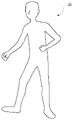
- FIG. 4A shows the skeleton generated by the skeleton generation unit 104.
- the example of FIG. 4A shows the case where the user A is viewed from the viewpoint (front view) of the camera 19 of FIG. 2 (the same applies to FIGS. 4B and 4C below).
- the skeleton 30 of FIG. 4A has a plurality of nodes 31 showing each end and each joint of the player's body.
- the skeleton 30 includes a player's head node 31a, chest node 31b, lumbar node 31c, shoulder node 31d, elbow node 31e, wrist node 31f, hand node 31g, knee node 31h, ankle node 31i and foot node. Including 31j.
- Adjacent nodes 31 are connected by bones 32.
- the skeleton generation unit 104 estimates the position and posture of each node 31 corresponding to the body part of the player with respect to the reference position and posture (for example, the initial position and posture at the start of the game). Generate skeleton 30.
- the estimated position and posture data of each node 31 is stored in the storage unit 12. Therefore, it is possible to accurately reflect the positional relationship in the depth direction for each part of the player's body.
- the skeleton generation unit 104 supplies the generated skeleton to the mesh generation unit 105.
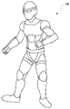
- the mesh generation unit 105 generates a player mesh structure that reflects the generated skeleton. For example, the mesh generation unit 105 generates the player's mesh structure 33 by modeling the skeleton with the mesh structure based on the shape of the player in the acquired image taken in the real space (see FIG. 4B). Modeling of the player's mesh structure is performed by a known method. The mesh generation unit 105 supplies the generated player mesh structure to the rendering unit 111.
- the rendering unit 111 renders the mesh structure of the player and the virtual object when viewed in the line-of-sight direction from the viewpoint position of the viewpoint information according to the viewpoint information of the camera 19. Specifically, the rendering unit 111 renders a virtual object, stores the color value in the pixel buffer 121, and sets the mesh structure of the player to, for example, white (RGB (255, 255, 255)) or gray (RGB (RGB (). It is rendered in 128, 128, 128)), rendered, and stored in the pixel buffer 121.
- the rendering unit 111 renders, as a virtual object for superimposing on the player's mesh structure, a virtual object that can be attached to at least a part of the player's mesh structure such as a player's avatar, costume, and decoration.
- the depth value (mesh depth value) of the player's mesh structure is written in the depth buffer (referred to as "mesh depth buffer") 122 for the player's mesh structure. If another virtual object exists in front of the player's mesh structure, the mesh depth value is not written to that pixel in the mesh depth buffer 122, or the mesh depth value is overwritten when the other virtual object is rendered. It will be erased. As a result, an area is generated only in the part where the player's mesh structure is drawn.
- the depth value (scene depth value) of the virtual object is written to the depth buffer (called “scene depth buffer”) 123 for virtual space rendering, and the context between the virtual objects is changed. It is judged. A specific depth value is not written in the scene depth buffer 123 for the pixel to which the virtual object is not drawn, and the scene depth value is infinite (undefined).
- the rendering unit 111 renders an expression related to light by a virtual object that will be superimposed on the mesh structure of the player.
- Expressions related to the light of a virtual object include, for example, shadows cast by the virtual object on the player's mesh structure, reflection of the virtual object on the player's mesh structure, translucency of the virtual object, and the player's mesh structure by a virtual light source.
- Shadow mapping can draw shadows and reflections using methods such as projecting a depth map from a light source onto a plane or ray tracing.
- the shadow or reflection of the virtual object on the user's mesh structure can be expressed. Since the user's mesh structure is rendered in solid white, it can be distinguished from the area where shadows and reflections are drawn. In this way, the image is given a representation of the light by the virtual object superimposed on the player's mesh structure.
- the rendering unit 111 supplies the rendered player's mesh structure and the rendered virtual object to the superimposing unit 112.
- the superimposing unit 112 superimposes the captured image on the mesh structure of the player rendered by the rendering unit 111. Specifically, the superimposing unit 112 superimposes the captured image on the region where the scene depth value is infinite and the region where the mesh depth value is written. The area written in the mesh depth value is superimposed on the captured image, leaving the color information of the shadow of the virtual object and the lighting expression (reflection, etc.). The superimposing unit 112 superimposes a virtual object on the mesh structure of the player on which the captured image is superposed.
- the superimposing unit 112 generates the player's avatar 34 by superimposing the virtual object of the avatar so as to be pasted on the mesh structure of the player.
- the whole body of the player is superimposed by the virtual object of the avatar, but the present invention is not limited to this, and a part of the body of the player may be superimposed by the virtual object.
- the mesh structure of the player on which the captured image is superimposed can be seen from the part other than the portion superimposed by the virtual object.
- the superimposing unit 112 supplies the superposed image to the post-process unit 113.
- the post-process unit 113 executes a process for expressing light by a virtual object on the superimposed image. Further, the post-process unit 113 executes a process for applying a drawing effect according to at least one of the position and the posture of the mesh structure of the player. This drawing effect includes, for example, motion blur according to a change in the position of the player's mesh structure, an aura that rises from the player's mesh structure according to the posture of the player's mesh structure, and the like. In addition to these, the post-process unit 113 may perform post-processes such as depth of field adjustment, tone mapping, and anti-aliasing to post-process the image so that it looks natural and smooth. The post-process unit 113 supplies the post-processed image to the distortion processing unit 114.
- the distortion processing unit 114 performs a process of distorting the post-processed image according to the distortion generated in the optical system of the camera 19.
- the distortion processing unit 114 supplies the image subjected to the distortion processing to the HDMI transmission / reception unit 106.
- the image generation unit 110 renders the player's mesh structure and virtual objects for each user A and B when viewed from the viewpoint position of each user A and B in the viewpoint direction.
- the image generation unit 110 generates an image by superimposing the rendered virtual object on the rendered mesh structure.
- the HDMI transmission / reception unit 106 transmits the image generated by the image generation unit 110 to the image providing device 21 according to HDMI.
- the image transmitted from the image generation device 100 is displayed on the display of the image providing device 21.
- the user B can see the image on which the virtual object is superimposed on the player.
- This image may be an AR image on which a video see-through image is superimposed as a background image of the player.
- this image may be a VR image on which a virtual object showing a virtual space is superimposed as a background image of the player.
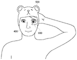
- FIG. 5 shows an example of a captured image captured by the camera 19.
- the photographed image of FIG. 5 is an image taken by the camera 19 of the user A who plays the game.
- the user A stands in front of the camera 19, and the face 400 of the user A is mainly photographed.
- FIG. 6 shows an example of an image in which a virtual object is superimposed on the captured image of FIG.
- the peripheral portion of the user A's face 400 is superimposed by the virtual object 500 of the bear's headgear.
- the user B can see an image in which the virtual object 500 of the bear's headgear is drawn around the face 400 of the user A through the image providing device 21.
- FIG. 7 is a diagram showing an example in which occlusion is expressed by a conventional method.
- FIG. 7 will be used to describe an example in which occlusion and depth are not properly represented.
- the example of FIG. 7 shows a user A trying to hide the face 400 with the hand 600.
- the hand 600 is reflected in the captured image at a position closer to the drawing than the face 400 of the user A.
- the virtual object 500 of the bear's headgear which should be on the back side in FIG. 7, may be superimposed on a part of the hand 600 of the user A, which should be on the front side in FIG. 7.
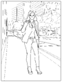
- FIG. 8 is a diagram showing an example in which occlusion is expressed by the method of this embodiment.
- the image generation device 100 of the present embodiment generates a player's mesh structure in which the skeleton of the player's body is reflected, and superimposes a virtual object on the player's mesh structure.
- the skeleton accurately reflects the positional relationship, including the depth of each part of the player's body. Therefore, according to the present embodiment, it is possible to more appropriately express the occlusion between the player's body and the virtual object superimposed on the player's mesh structure. As a result, the depth is appropriately expressed, a sense of unity is obtained between the player's body and the virtual object, and it is possible to provide a natural image.
- the viewpoint information includes the viewpoint position and the viewpoint direction of the spectator different from the player. According to this configuration, it is possible to provide an image to the spectator from the viewpoint of a third party (spectator) in which the depth of the player is appropriately expressed.
- the image generation unit 110 generates an image so as to give an expression related to light by a virtual object superimposed on the mesh structure of the player.
- the player's mesh structure generated based on the skeleton accurately reflects the positional relationship of each part of the player's body, so that the player's body more accurately reflects the expression of light by the virtual object. It becomes possible to provide an image.
- the image generation unit 110 generates an image so as to give a drawing effect corresponding to at least one of the position and the posture of the mesh structure of the player. According to this configuration, since the mesh structure of the player appropriately reflects the positional relationship of each part of the player's body, it is possible to more appropriately express drawing effects such as motion blur.
- the captured image is superimposed on the mesh structure of the player, and the virtual object is superimposed on the mesh structure of the player on which the captured image is superimposed. Therefore, according to this configuration, it is possible to more accurately represent the occlusion between the superimposed part of the virtual object in the player's body and the other parts of the player's body that reflect the actual appearance of the player. It becomes.
- FIG. 9 is a configuration diagram of the image generation device of the second embodiment.
- the image generation device 100 of the present embodiment further includes a depth acquisition unit 107 and a real space depth buffer 124.
- an AR image on which a video see-through image is superimposed is provided as a background image of the player.
- the depth acquisition unit 107 acquires depth information in the real space.
- the depth information of the real space of this embodiment is acquired from the camera 19.
- Depth information in the real space may be acquired using, for example, a depth sensor of a method such as an infrared pattern, Structured Light, or TOF (Time Of Flight).
- the depth acquisition unit 107 supplies the acquired depth information to the mesh generation unit 105.
- the mesh generation unit 105 of the present embodiment generates a mesh structure in the real space including the mesh structure of the player. Specifically, the mesh generation unit 105 generates the mesh structure of the real space by modeling the real space with the mesh structure based on the depth information of the real space. Modeling of the mesh structure in real space is performed by a known method.
- Real space mesh structures include real space walls, floors, ceilings, stationary objects, and the like.
- the rendering unit 111 renders the mesh structure in the real space in, for example, white (RGB (255, 255, 255)) and stores it in the pixel buffer 121.
- the depth value of the real object (referred to as "real space depth value") is written in the real space depth buffer 124 for real space rendering.
- the real space depth value is used to determine the context between real objects.
- the real space depth value is generated based on the depth information in the real space.
- FIG. 10A shows the mesh structure of the player on which the captured image in the real space is superimposed.
- a virtual object see FIG. 10B
- the leg portion of the mesh structure may protrude from the virtual object of the leg portion of the mechanical structure.
- the virtual objects of the legs of the mesh structure and the legs of the mechanical structure do not fit, and tend to be unnatural.
- the post-process unit 113 of the present embodiment when the mesh structure portion of the player on which the virtual object is superimposed protrudes from the superimposed virtual object, the superimposed portion does not protrude from the virtual object.
- a process is applied to distort the space around the skeleton in that part.
- a process of distorting this space is performed in at least one of the horizontal direction and the vertical direction.
- the legs of the player's mesh structure are moved along the bones 32 connecting the waist node 31c, the knee node 31h, the ankle node 31i, and the foot node 31j of the skeleton (see FIG. 4). Distort the surrounding space.
- a process of attracting pixels in the space around the bone 32 is performed. The closer it is to the bone, the greater the amount of pixel attraction. This makes it possible to make the legs of the player's mesh structure thinner.
- FIG. 10D The virtual object of the leg of the mechanical structure is superimposed on the leg of the mesh structure of the player after this processing. As shown in FIG. 10D, only the virtual object of the leg of the mechanical structure can be seen in the leg of the player.
- the virtual object can be fitted to the mesh structure of the player. Therefore, it is possible to suppress the occurrence of discomfort due to the difference in the mesh structure of the player and the size of the virtual object.
- the case where the mesh structure of the player protrudes from the superimposed virtual object is taken as an example, but the present invention is not limited to this.
- the space around it can be distorted to crush a part of the player's mesh structure. good.
- the player's avatar itself is set as a very heavy avatar (for example, a giant rock-like alien avatar), the space near the floor on which the avatar stands may be distorted. .. In this way, it is possible to make the player's mesh structure look smaller according to the characteristics of the virtual object.
- At least some of the functions of the image generator 100 may be implemented in the HMD 15 or the image providing device 21. Alternatively, at least a part of the functions of the image generation device 100 may be implemented in a server connected to the image generation device 100 via a network.
- the image generator 100 may be further connected to the server via a network.
- the server may provide the image generator 100 with an online application such as a game in which a plurality of users can participate via a network.
- the HMD 15 or the image providing device 21 may be connected to a computer or a mobile terminal instead of the image generating device 100.
- the user A is a player who plays the game
- the user B is a spectator who watches the play of the user A in the game
- both users A and B may be players playing the game.
- the player recognition unit 102 recognizes the player's body based on the captured image supplied from the camera 19, but the present invention is not limited to this.
- the player's body may be recognized by detecting the position and posture of the user's body part using a tracker.
- the HMD 15 may not be provided.
- the image of the image generation device 100 may be supplied to a separately provided display, and the user A may play the game based on the image displayed on the display.
- the user B also wears the HMD 15, supplies the captured image of the HMD 15 of the user B to the image generation device 100 instead of the captured image of the camera 19, and is generated by the image generation device 100 based on the viewpoint information of the HMD 15.
- the resulting image may be displayed on the HMD 15.
- the camera 19 and the image providing device 21 are separate bodies, but may be integrally configured.
- a personal computer or the like having a shooting function and a display function may be used.
- the captured image is superimposed on the virtual object of the player, but only the virtual object may be superimposed on the mesh structure without superimposing the captured image.
- processing such as depth of field adjustment, tone mapping, and antialiasing was illustrated as a post process, but it may also be called a post process including distortion processing, simple enlargement / reduction, and trapezoidal conversion.
- This disclosure relates to an image generator, an image generation method, and a program.
- 10 image generation system 15 HMD, 100 image generator, 101 captured image acquisition unit, 102 player recognition unit, 103 viewpoint acquisition unit, 104 skeleton generation unit, 105 mesh generation unit, 106 HDMI transmission / reception unit, 107 depth acquisition unit, 110 Image generation unit, 111 rendering unit, 112 superimposition unit, 113 post process unit, 114 distortion processing unit, 121 pixel buffer, 122 mesh depth buffer, 123 scene depth buffer, 124 real space depth buffer.
Abstract
本開示の画像生成装置100は、プレイヤーの体を認識するプレイヤー認識部102と、視点位置及び視点方向を含む視点情報を取得する視点取得部103と、認識結果に基づいて、プレイヤーの体のスケルトンが反映されたプレイヤーのメッシュ構造を生成するメッシュ生成部105と、視点情報における視点位置から視点方向に見たときのプレイヤーのメッシュ構造及び仮想オブジェクトをレンダリングし、レンダリングされたプレイヤーのメッシュ構造にレンダリングされた仮想オブジェクトを重畳することにより、画像を生成する画像生成部110と、を含む。
Description
本開示は、画像生成装置、画像生成方法、およびプログラムに関する。
ゲーム機に接続されたヘッドマウントディスプレイ(HMD)を頭部に装着して、HMDに表示された画面を見ながら、コントローラなどを操作してゲームプレイすることが行われている。HMDを装着すると、HMDに表示される映像以外をユーザは見ないため、映像世界への没入感が高まり、ゲームのエンタテインメント性を一層高める効果がある。また、HMDに仮想現実(VR)の映像を表示させ、HMDを装着したユーザが頭部を回転させると、360度見渡せる全周囲の仮想空間が表示されるようにすると、さらに映像への没入感が高まり、ゲームなどのアプリケーションの操作性も向上する。
また、HMDに搭載されたカメラによって外界の映像を撮影してディスプレイパネルに表示することのできるビデオ透過(ビデオシースルー)型HMDもある。ビデオ透過型HMDでは、カメラで撮影される外界の映像にコンピュータグラフィックス(CG)によって生成された仮想世界のオブジェクトを重畳させることで拡張現実(AR)の映像を生成して表示することもできる。拡張現実の映像は、現実世界から切り離された仮想現実とは違って、現実世界が仮想オブジェクトで拡張されたものであり、ユーザは現実世界とのつながりを意識しつつ、仮想世界を体験することができる。
ゲームをプレイするプレイヤーの画像に対して仮想オブジェクトを重畳させた画像を表示する場合、奥にあるはずの仮想オブジェクトが手前にあるはずのプレイヤーの体の一部を上書きしてしまうことがある。そのため、奥行きが正確に表現できない場合がある。その結果、プレイヤーの体と仮想オブジェクトとの間で一体感が得られず、画像が不自然なものとなる。
上記課題に鑑みて、本開示の1つの目的は、プレイヤーの体とそのプレイヤーの体に重畳された仮想オブジェクトについて奥行きがより正確に表現された画像を提供することが可能な画像生成装置、画像生成方法、およびプログラムを提供することにある。
上記課題を解決するために、本開示のある態様の画像生成装置は、プレイヤーの体を認識するプレイヤー認識部と、視点位置及び視点方向を含む視点情報を取得する視点取得部と、前記認識結果に基づいて、前記プレイヤーの体のスケルトンが反映されたプレイヤーのメッシュ構造を生成するメッシュ生成部と、前記視点情報における前記視点位置から前記視点方向に見たときの前記プレイヤーのメッシュ構造及び仮想オブジェクトをレンダリングし、前記レンダリングされたプレイヤーのメッシュ構造に前記レンダリングされた仮想オブジェクトを重畳することにより、画像を生成する画像生成部と、を含む。
本開示の別の態様の画像生成方法は、プレイヤーの体を認識するステップと、視点位置及び視点方向に関する視点情報を取得するステップと、前記認識結果に基づいて、前記プレイヤーの体のスケルトンが反映されたプレイヤーのメッシュ構造を生成するステップと、前記視点情報における前記視点位置から前記視点方向に見たときの前記プレイヤーのメッシュ構造及び仮想オブジェクトをレンダリングし、前記レンダリングされたプレイヤーのメッシュ構造に前記レンダリングされた仮想オブジェクトを重畳することにより、画像を生成するステップと、を含む。
本開示のさらに別の態様のプログラムは、プレイヤーの体を認識するステップと、視点位置及び視点方向に関する視点情報を取得するステップと、前記認識結果に基づいて、前記プレイヤーの体のスケルトンが反映されたプレイヤーのメッシュ構造を生成するステップと、前記視点情報における前記視点位置から前記視点方向に見たときの前記プレイヤーのメッシュ構造及び仮想オブジェクトをレンダリングし、前記レンダリングされたプレイヤーのメッシュ構造に前記レンダリングされた仮想オブジェクトを重畳することにより、画像を生成するステップと、をコンピュータに実行させるためのプログラムである。
なお、以上の構成要素の任意の組合せ、本開示の表現を方法、装置、システム、コンピュータプログラム、データ構造、記録媒体などの間で変換したものもまた、本開示の態様として有効である。
本開示によれば、プレイヤーの体とそのプレイヤーの体に重畳された仮想オブジェクトについて奥行きがより正確に表現された画像を提供することが可能となる。
<第1実施形態>
図1は、第1実施形態の画像生成システムの全体概要図である。図1の画像生成システム10は、画像生成装置100を含む。画像生成装置100の一例は、ゲーム機である。画像生成装置100は、ヘッドマウントディスプレイ(HMD)15、カメラ19、及び画像提供装置21に接続される。画像生成装置100に接続されるHMD15の数は、図1の例に限定されるものではない。
図1は、第1実施形態の画像生成システムの全体概要図である。図1の画像生成システム10は、画像生成装置100を含む。画像生成装置100の一例は、ゲーム機である。画像生成装置100は、ヘッドマウントディスプレイ(HMD)15、カメラ19、及び画像提供装置21に接続される。画像生成装置100に接続されるHMD15の数は、図1の例に限定されるものではない。
画像生成装置100は、制御部11と、記憶部12と、インタフェース部13と、を含む。制御部11はプロセッサを含み、記憶部12に記憶されているプログラムを実行して各種の情報処理を実行する。記憶部12は、RAM等のメモリデバイスを含み、制御部11が実行するプログラム、及び当該プログラムによって処理されるデータを格納する。
インタフェース部13は、HMD15、カメラ19、及び画像提供装置21のそれぞれの間のデータ通信のためのインタフェースである。画像生成装置100は、インタフェース部13を介して有線又は無線でHMD15と、カメラ19と、画像提供装置21と、に接続される。具体的には、インタフェース部13は、映像・音声をデジタル信号で伝送する通信インタフェースの標準規格であるHDMI(登録商標)(High-Definition Multimedia Interface)等のマルチメディアインタフェースを含む。
HMD15は、ユーザの頭部に装着してディスプレイに表示される静止画や動画などを鑑賞し、ヘッドホンから出力される音声や音楽などを聴くための視聴装置である。HMD15には、ジャイロセンサや加速度センサが設けられる。HMD15は、これらのセンサを用いて、HMD15を装着したユーザの頭部の位置情報と頭部の回転角や傾きなどを計測する。HMD15には、カメラユニット(不図示)が搭載される。HMD15は、カメラユニットを用いて、ユーザがHMD15を装着している間、そのユーザの視点で外界を撮影することができる。HMD15は、その撮影した撮影画像を画像生成装置100に供給する。HMD15は、その撮影画像に基づいて画像生成装置100によって生成された画像をディスプレイに表示する。
カメラ19は、ゲームのプレイヤー及びその周囲に存在する床や壁などの物体を撮影できるように設置される。カメラ19は、撮影した現実空間の撮影画像を画像生成装置100に供給する。
画像提供装置21は、画像生成装置100からその生成された画像を受信し、その受信した画像をユーザに提供可能に構成される。画像提供装置21は、画像生成装置100から受信した画像を表示可能に構成される。また、画像提供装置21は、受信した画像をコンテンツファイルとして動画配信サーバ(不図示)にアップロード可能に構成される。
画像生成装置100は、ユーザによる操作情報を入力するための入力部(不図示)に接続されてもよい。画像生成装置100は、通信ネットワークを介して外部とデータ通信を行うための通信インタフェースを有してもよい。
図2は、ユーザによる本実施形態の利用例を示す。図2の例では、ユーザAは、ゲームをプレイするプレイヤーであり、HMD15を装着している。図2の例では、ユーザBは、ゲーム内でのユーザAのプレイを観戦する観戦者であり、画像提供装置21によって表示されるユーザAのプレイ画像を視聴している。また、図2の例では、カメラ19はユーザAの正面からユーザAを撮影するように配置される。ただし、この配置に限定されず、カメラ19はユーザAの真横、真後ろ、斜め横等の任意の位置からユーザAを撮影するように配置されてもよい。後述するように、本実施形態では、プレイヤーの体と仮想オブジェクトとの間のオクルージョンをより正確に表現することが可能となる。そのため、例えば、図2のように観戦者がプレイヤーの視点とは異なる第三者の視点でプレイヤーのゲームプレイを観戦する場合に好適である。そのほかにも、ゲームのプレイヤーが自身のゲームプレイの様子を第三者視点のカメラ19で撮影して、画像提供装置21を介してそのゲームプレイを他のユーザに配信する場合に好適である。
図3は、本実施形態の画像生成装置の構成図である。画像生成装置100は、プレイヤー認識部102と、撮影画像取得部101と、視点取得部103と、スケルトン生成部104と、メッシュ生成部105と、画像生成部110と、HDMI送受信部106と、を含む。画像生成部110は、レンダリング部111と、重畳部112と、ポストプロセス部113と、歪み処理部114と、を含む。図3は機能に着目したブロック図を描いており、これらの機能ブロックはハードウエアのみ、ソフトウエアのみ、またはそれらの組合せによっていろいろな形で実現することができる(後述する図9も同様である)。
以下、第三者視点の画像を生成する場合を例に、本実施形態について説明する。具体的には、図2の例のように、ユーザBがユーザAのゲームプレイを観戦するためにカメラ19の視点の画像を生成する場合について説明する。ユーザA(プレイヤー)のHMD15及び画像提供装置21には、各々の視点で生成された同じゲームプレイ(ユーザAのゲームプレイ)の画像が供給されるものとする。
撮影画像取得部101は、現実空間の撮影画像を取得する。本実施形態の現実空間の撮影画像は、カメラ19からHDMI送受信部106を介して取得される。撮影画像取得部101は、取得した各撮影画像をプレイヤー認識部102、視点取得部103及び重畳部112に供給する。
プレイヤー認識部102は、プレイヤーの体を認識する。具体的には、プレイヤー認識部102は、撮影画像取得部101で取得された撮影画像におけるユーザAの各身体部位の位置及び姿勢に基づいて、プレイヤーの体の各身体部位の位置及び姿勢を認識する。例えば、プレイヤー認識部102は、カメラ19の撮影画像に基づいて、学習済みの機械学習モデルを用いてプレイヤーの各部位の位置及び姿勢を推定することで、プレイヤーの体を認識する。例えば、プレイヤー認識部102は、オープンポーズ(Open Pose)などを用いてプレイヤーの体を認識することができる。プレイヤー認識部102は、その認識結果をスケルトン生成部104に供給する。
視点取得部103は、カメラ19から撮影画像取得部101を介して供給された撮影画像に基づいて、カメラ19の視点位置および視線方向を含む視点情報を取得する。視点取得部103は、取得した各視点情報をレンダリング部111に供給する。カメラ19の視点情報は、プレイヤーの視点とは異なる観戦者の視点情報の一例である。
スケルトン生成部104は、プレイヤー認識部102の認識結果に基づいて、プレイヤーの体のスケルトンを生成する。例えば、スケルトン生成部104は、プレイヤーの体の各身体部位の位置及び姿勢の認識結果に基づいて、学習済みの機械学習モデルを用いてプレイヤーのスケルトンにおける各部位の位置及び姿勢を推定することで、このスケルトンを生成する。例えば、スケルトン生成部104は、オープンポーズ(Open Pose)などを用いてスケルトンを生成することができる。
図4Aは、スケルトン生成部104が生成するスケルトンを示す。図4Aの例は、図2のカメラ19の視点(正面視)からユーザAを見たときの場合を示す(以下の図4B及び図4Cも同様である)。図4Aのスケルトン30は、プレイヤーの体の各端部及び各関節を示す複数のノード31を有する。具体的には、スケルトン30は、プレイヤーの頭部ノード31a、胸部ノード31b、腰部ノード31c、肩ノード31d、肘ノード31e、手首ノード31f、手ノード31g、膝ノード31h、足首ノード31i及び足ノード31jを含む。隣接するノード31は、ボーン32によって接続される。本実施形態では、スケルトン生成部104は、プレイヤーの身体部位に対応する各ノード31の基準の位置及び姿勢(例えば、ゲーム開始時の初期の位置及び姿勢)に対する位置及び姿勢を推定することにより、スケルトン30を生成する。推定された各ノード31の位置及び姿勢のデータは、記憶部12に記憶される。そのため、プレイヤーの体の各部位についての奥行き方向の位置関係を正確に反映することが可能となる。スケルトン生成部104は、生成したスケルトンをメッシュ生成部105に供給する。
メッシュ生成部105は、生成されたスケルトンが反映されたプレイヤーのメッシュ構造を生成する。例えば、メッシュ生成部105は、取得された現実空間の撮影画像におけるプレイヤーの形状に基づいて、スケルトンをメッシュ構造でモデル化することで、プレイヤーのメッシュ構造33を生成する(図4B参照)。プレイヤーのメッシュ構造のモデル化は、公知の方法により行われる。メッシュ生成部105は、生成したプレイヤーのメッシュ構造をレンダリング部111に供給する。
レンダリング部111は、カメラ19の視点情報にしたがって、その視点情報の視点位置から視線方向に見たときにおける、プレイヤーのメッシュ構造と仮想オブジェクトとをそれぞれレンダリングする。具体的には、レンダリング部111は、仮想オブジェクトをレンダリングしてカラー値を画素バッファ121に保存するとともに、プレイヤーのメッシュ構造をたとえば白(RGB(255,255,255))、またはグレー(RGB(128,128,128))でレンダリングしてレンダリングして画素バッファ121に保存する。レンダリング部111は、プレイヤーのメッシュ構造への重畳用の仮想オブジェクトとして、例えば、プレイヤーのアバター、衣装、装飾品等のプレイヤーのメッシュ構造の少なくとも一部に装着可能な仮想オブジェクトをレンダリングする。
レンダリング部111がプレイヤーのメッシュ構造をレンダリングする際、プレイヤーのメッシュ構造の奥行き値(メッシュデプス値)がプレイヤーのメッシュ構造用のデプスバッファ(「メッシュデプスバッファ」と呼ぶ)122に書き込まれる。プレイヤーのメッシュ構造よりも手前側に他の仮想オブジェクトが存在する場合は、その画素にはメッシュデプスバッファ122においてメッシュデプス値が書き込まれないか、又は他の仮想オブジェクトのレンダリング時にメッシュデプス値が上書き消去される。その結果、プレイヤーのメッシュ構造が描画されている部分のみの領域が生成される。
レンダリング部111が仮想オブジェクトをレンダリングする際、仮想オブジェクトの奥行き値(シーンデプス値)が仮想空間レンダリング用のデプスバッファ(「シーンデプスバッファ」と呼ぶ)123に書き込まれ、仮想オブジェクト間の前後関係が判定される。仮想オブジェクトが描画されない画素はシーンデプスバッファ123において具体的なデプス値が書き込まれず、シーンデプス値は無限大(不定)である。
さらに、レンダリング部111は、プレイヤーのメッシュ構造に重畳されることになる仮想オブジェクトによる光に関する表現をレンダリングする。仮想オブジェクトの光に関する表現としては、例えば、仮想オブジェクトがプレイヤーのメッシュ構造に落とす影や仮想オブジェクトのプレイヤーのメッシュ構造への映り込み、仮想オブジェクトの半透明化、仮想光源によるプレイヤーのメッシュ構造へのライティング表現などが挙げられる。たとえばシャドウマッピングは光源からの深度マップを平面に投影する方法やレイトレーシングなどの手法を用いて影や映り込みを描画することができる。仮想オブジェクトの影や映り込みの半透明の画像をユーザのメッシュ構造に重畳することでユーザのメッシュ構造に対する仮想オブジェクトの影や映り込みを表現することができる。ユーザのメッシュ構造は白一色でレンダリングされているため、影や映り込みが描画された領域とは区別することができる。このようにして、プレイヤーのメッシュ構造に重畳される仮想オブジェクトによる光に関する表現が画像に付与される。
レンダリング部111は、レンダリングされたプレイヤーのメッシュ構造とレンダリングした仮想オブジェクトとを重畳部112に供給する。
重畳部112は、レンダリング部111がレンダリングしたプレイヤーのメッシュ構造に撮影画像を重畳する。具体的には、重畳部112は、シーンデプス値が無限の領域とメッシュデプス値が書き込まれている領域とに、撮影画像を重畳する。メッシュデプス値に書き込まれている領域は、仮想オブジェクトの影やライティング表現(映りこみなど)の色情報を残して撮影画像と重畳する。重畳部112は、撮影画像が重畳されたプレイヤーのメッシュ構造に仮想オブジェクトを重畳する。
図4Cを参照する。重畳部112は、アバターの仮想オブジェクトをプレイヤーのメッシュ構造の上に貼り付けられるように重畳することにより、プレイヤーのアバター34を生成する。ここで、図4Cの例では、プレイヤーの全身がアバターの仮想オブジェクトによって重畳されたが、これに限定されず、プレイヤーの体の一部が仮想オブジェクトによって重畳されてもよい。この場合、仮想オブジェクトによって重畳される部分以外の箇所からは、撮影画像が重畳されたプレイヤーのメッシュ構造が見えるようになる。
重畳部112は、重畳した画像をポストプロセス部113に供給する。
ポストプロセス部113は、重畳された画像に対して、仮想オブジェクトによる光に関する表現を施すための処理を実行する。また、ポストプロセス部113は、プレイヤーのメッシュ構造の位置及び姿勢の少なくとも一方に応じた描画エフェクトを施すための処理を実行する。この描画エフェクトは、例えば、プレイヤーのメッシュ構造の位置の変化に応じたモーションブラー、プレイヤーのメッシュ構造の姿勢に応じてプレイヤーのメッシュ構造から立ち上がるオーラ等を含む。ポストプロセス部113は、これら以外にも、被写界深度調整、トーンマッピング、アンチエイリアシングなどのポストプロセスを施し、画像が自然で滑らかに見えるように後処理してもよい。ポストプロセス部113は、ポストプロセスが施された画像を歪み処理部114に供給する。
歪み処理部114は、ポストプロセスが施された画像に対してカメラ19の光学系で生じる歪みに合わせて画像を変形(distortion)させて歪ませる処理を施す。歪み処理部114は、歪ませる処理が施された画像をHDMI送受信部106に供給する。
以上のようにして、画像生成部110は、ユーザA及びB毎に、各ユーザA及びBの視点位置から視点方向に見たときのプレイヤーのメッシュ構造及び仮想オブジェクトをレンダリングする。画像生成部110は、そのレンダリングされたメッシュ構造にそのレンダリングされた仮想オブジェクトを重畳することにより、画像を生成する。
HDMI送受信部106は、画像生成部110により生成された画像をHDMIにしたがって画像提供装置21に伝送する。画像生成装置100から伝送された画像は、画像提供装置21のディスプレイに表示される。これによりユーザBは、プレイヤーに仮想オブジェクトが重畳された画像を見ることができる。この画像は、プレイヤーの背景画像としてビデオシースルー画像が重畳されたAR画像であってもよい。あるいは、この画像は、プレイヤーの背景画像として仮想空間を示す仮想オブジェクトが重畳されたVR画像であってもよい。
ここで、図5~図8を参照して、ゲームをプレイするプレイヤーの画像に仮想オブジェクトを重畳させた画像について説明する。
図5は、カメラ19により撮影される撮影画像の例を示す。図5の撮影画像は、カメラ19がゲームをプレイするユーザAを撮影したものである。図5の例では、ユーザAはカメラ19の正面に立っており、ユーザAの顔400が主に撮影されている。
図6は、図5の撮影画像に仮想オブジェクトを重畳した画像の例を示す。図6に示すように、ユーザAの顔400の周囲の部分は熊の被り物の仮想オブジェクト500によって重畳される。これにより、ユーザBはユーザAの顔400の周囲に熊の被り物の仮想オブジェクト500が描かれた画像を画像提供装置21を介して見ることができる。
図7は、従来手法によってオクルージョンを表現した例を示す図である。比較のため、図7を用いてオクルージョン及び奥行きが適切に表現されない例を説明する。図7の例は、ユーザAが手600で顔400を隠そうとしている様子を示す。ユーザAが手600で顔400を隠すように手600を顔400の前に持っていくと、撮影画像にはユーザAの顔400よりも図面手前側の位置において手600が映り込む。このとき、図7において奥側にあるはずの熊の被り物の仮想オブジェクト500が、図7において手前側にあるはずのユーザAの手600の一部に重畳される場合がある。熊の被り物の仮想オブジェクト500とユーザAの手600の一部との位置関係が正しく判定されない場合があるためである。そのため、従来手法では、本来見えるはずのユーザAの手600の一部が熊の被り物の仮想オブジェクト500によって見えなくなるような不適切なオクルージョンが発生する。その結果、奥行きや適切に表現されず、プレイヤーの体と仮想オブジェクトとの間で一体感が得られなくなって画像が不自然なものとなる。そのため、プレイヤーの体の各部位とプレイヤーに重畳される画像との位置関係を正しく表現する必要がある。
図8は、本実施形態の手法によってオクルージョンを表現した例を示す図である。本実施形態の画像生成装置100は、プレイヤーの体のスケルトンが反映されたプレイヤーのメッシュ構造を生成し、そのプレイヤーのメッシュ構造に仮想オブジェクトを重畳する。上述したように、スケルトンはプレイヤーの体の各部位の奥行きを含む位置関係を正確に反映する。そのため、本実施形態によると、プレイヤーの体とプレイヤーのメッシュ構造に重畳される仮想オブジェクトとの間のオクルージョンをより適切に表現することが可能となる。その結果、奥行きが適切に表現され、プレイヤーの体と仮想オブジェクトとの間で一体感が得られるようになり、自然な画像を提供することが可能となる。
本実施形態では、視点情報は、プレイヤーとは異なる観戦者の視点位置及び視点方向を含む。本構成によると、プレイヤーの奥行きが適切に表現された第三者(観戦者)の視点の画像を観戦者に画像を提供することが可能となる。
本実施形態では、画像生成部110は、プレイヤーのメッシュ構造に重畳された仮想オブジェクトによる光に関する表現を付与するように画像を生成する。従来、プレイヤーの体に仮想オブジェクトによる光に関する表現を正確に反映させることができなかった。本構成によると、スケルトンに基づいて生成されたプレイヤーのメッシュ構造がプレイヤーの体の各部位の位置関係を正確に反映するため、プレイヤーの体に仮想オブジェクトによる光に関する表現がより正確に反映された画像を提供することが可能となる。
本実施形態では、画像生成部110は、プレイヤーのメッシュ構造の位置及び姿勢のうちの少なくとも1つに応じた描画エフェクトを付与するように、画像を生成する。本構成によると、プレイヤーのメッシュ構造がプレイヤーの体の各部位の位置関係を適切に反映しているため、モーションブラー等の描画エフェクトをより適切に表現することが可能となる。
本実施形態では、プレイヤーのメッシュ構造に撮影画像が重畳され、その撮影画像が重畳されたプレイヤーのメッシュ構造に仮想オブジェクトを重畳される。そのため、本構成によると、プレイヤーの体において仮想オブジェクトが重畳させた部分と、プレイヤーの現実の外見が反映されたプレイヤーの体の他の部分との間のオクルージョンをより正確に表現することが可能となる。
<第2実施形態>
以下、本開示の第2実施形態を説明する。以下の実施形態の図面および説明では、第1実施形態と同一または同等の構成要素、部材には、同一の符号を付する。第1実施形態と重複する説明を適宜省略し、第1実施形態と相違する構成について重点的に説明する。
以下、本開示の第2実施形態を説明する。以下の実施形態の図面および説明では、第1実施形態と同一または同等の構成要素、部材には、同一の符号を付する。第1実施形態と重複する説明を適宜省略し、第1実施形態と相違する構成について重点的に説明する。
図9は、第2実施形態の画像生成装置の構成図である。本実施形態の画像生成装置100は、奥行き取得部107と、実空間デプスバッファ124と、をさらに備える。本実施形態では、プレイヤーの背景画像としてビデオシースルー画像が重畳されたAR画像が提供される。
奥行き取得部107は、現実空間の奥行き情報を取得する。本実施形態の現実空間の奥行き情報は、カメラ19から取得される。現実空間の奥行き情報は、たとえば、赤外線パターン、Structured Light、TOF(Time Of Flight)などの方式のデプスセンサを用いて取得されてもよい。奥行き取得部107は、取得した奥行き情報をメッシュ生成部105に供給する。
本実施形態のメッシュ生成部105は、プレイヤーのメッシュ構造を含む現実空間のメッシュ構造を生成する。具体的には、メッシュ生成部105は、現実空間の奥行き情報に基づいて、現実空間をメッシュ構造でモデル化することにより、現実空間のメッシュ構造を生成する。現実空間のメッシュ構造のモデル化は、公知の方法により行われる。現実空間のメッシュ構造は、現実空間の壁、床、天井、静止物体などを含む。
レンダリング部111は、現実空間のメッシュ構造をたとえば白(RGB(255,255,255))でレンダリングして画素バッファ121に保存する。レンダリング部111が現実オブジェクトをレンダリングする際、現実オブジェクトの奥行き値(「実空間デプス値」と呼ぶ)が現実空間レンダリング用の実空間デプスバッファ124に書き込まれる。実空間デプス値は、現実オブジェクト間の前後関係を判定する際に用いられる。実空間デプス値は、現実空間の奥行き情報に基づいて生成される。
本実施形態によると、プレイヤーのメッシュ構造を含む現実空間のメッシュ構造の位置関係を適切に表現することが可能となる。その結果、プレイヤーのメッシュ構造に重畳された仮想オブジェクトとその周囲に存在する物体(例えばボールなど)との間のオクルージョンをより適切に表現することが可能となる。その結果、現実空間のメッシュ構造の奥行きをより正確に表現することが可能となる。
<第3実施形態>
以下、本開示の第3実施形態を説明する。
以下、本開示の第3実施形態を説明する。
図10Aは、現実空間の撮影画像が重畳されたプレイヤーのメッシュ構造を示す。図10Aのプレイヤーのメッシュ構造における脚部に、機械構造の脚部の仮想オブジェクト(図10B参照)を重畳する場合を考える。図10Bに示すように、重畳する機械構造の脚部の仮想オブジェクトがメッシュ構造における脚部よりも小さい場合、メッシュ構造の脚部が機械構造の脚部の仮想オブジェクトからはみ出てしまうことがある。この場合、メッシュ構造の脚部と機械構造の脚部の仮想オブジェクトがフィットせず、不自然になりやすくなる。
そこで、本実施形態のポストプロセス部113は、仮想オブジェクトが重畳されるプレイヤーのメッシュ構造の部分がその重畳される仮想オブジェクトからはみ出る場合、その重畳される部分が仮想オブジェクトからはみ出さなくなるように、その部分におけるスケルトンの周囲の空間を歪ませる処理を施す。ここでは、水平方向と鉛直方向との少なくとも一方について、この空間を歪ませる処理が行われる。以下、図10C及び図10Dを用いてこの処理について説明する。
図10Cを参照する。図10Cの処理では、まず、プレイヤーのメッシュ構造の脚部を、スケルトンの腰部ノード31c、膝ノード31h、足首ノード31i及び足ノード31jをそれぞれ接続するボーン32に沿って(図4参照)、その周囲の空間を歪ませる。本実施形態では、ボーン32に向かってその周囲の空間の画素を引き寄せる処理が行われる。ボーンに近いほど、画素の引き寄せ量が大きくなる。これにより、プレイヤーのメッシュ構造の脚部を細くすることができる。
図10Dを参照する。この処理後のプレイヤーのメッシュ構造の脚部に機械構造の脚部の仮想オブジェクトを重畳する。図10Dに示すように、プレイヤーの脚部には、機械構造の脚部の仮想オブジェクトのみが見えるようになる。
本構成によると、プレイヤーの体の部位と比較して小さい仮想オブジェクトを重畳する場合であっても、仮想オブジェクトをプレイヤーのメッシュ構造に対してフィットさせることができる。そのため、プレイヤーのメッシュ構造と仮想オブジェクトの大きさの違いによる違和感の発生を抑制することが可能となる。
本実施形態では、プレイヤーのメッシュ構造がその重畳される仮想オブジェクトからはみ出る場合を例にしたが、これに限定されない。例えば、プレイヤーのメッシュ構造の一部の上(例えば頭部の上)に非常に重い物体がある場合には、プレイヤーのメッシュ構造の一部を押しつぶすように、その周囲の空間を歪ませてもよい。また、例えば、プレイヤーのアバター自体が非常に重いアバター(例えば巨大な岩のような宇宙人のアバターなど)として設定されている場合、そのアバターが立っている床付近の空間を歪ませてもよい。このように、仮想オブジェクトの特性に合わせてプレイヤーのメッシュ構造を小さく見せることが可能となる。
<変形例>
画像生成装置100の少なくとも一部の機能は、HMD15又は画像提供装置21に実装されてもよい。あるいは、画像生成装置100の少なくとも一部の機能は、ネットワークを介して画像生成装置100に接続されたサーバに実装されてもよい。
画像生成装置100の少なくとも一部の機能は、HMD15又は画像提供装置21に実装されてもよい。あるいは、画像生成装置100の少なくとも一部の機能は、ネットワークを介して画像生成装置100に接続されたサーバに実装されてもよい。
画像生成装置100は、さらにネットワークを介してサーバに接続されてもよい。その場合、サーバは、複数のユーザがネットワークを介して参加できるゲームなどのオンラインアプリケーションを画像生成装置100に提供してもよい。HMD15又は画像提供装置21は、画像生成装置100の代わりに、コンピュータや携帯端末に接続されてもよい。
上記実施形態では、ユーザAはゲームをプレイするプレイヤーとし、ユーザBはゲーム内でのユーザAのプレイを観戦する観戦者としたが、これに限定されない。例えば、ユーザA及びBの両方がゲームをプレイするプレイヤーであってもよい。
上記実施形態では、プレイヤー認識部102は、カメラ19から供給された撮影画像に基づいてプレイヤーの体を認識したが、これに限定されない。例えば、トラッカを用いてユーザの身体部位の位置や姿勢を検出することによってプレイヤーの体を認識してもよい。
上記実施形態では、ゲームをプレイするユーザAがHMD15を装着した例を示したが、HMD15は設けられなくてもよい。この場合、例えば、別途設けられたディスプレイに画像生成装置100の画像を供給し、このディスプレイに表示された画像を基にユーザAがゲームをプレイすればよい。
上記実施形態では、カメラ19及び画像提供装置21を用いた例を示したが、これらは用いられなくてもよい。この場合、例えば、ユーザBもHMD15を装着し、ユーザBのHMD15の撮影画像をカメラ19の撮影画像の代わりに画像生成装置100に供給し、HMD15の視点情報に基づいて画像生成装置100によって生成された画像をHMD15で表示すればよい。
図2の例では、カメラ19及び画像提供装置21は別体であるが、一体で構成されてもよい。この場合、例えば、撮影機能と表示機能を有するパーソナルコンピュータ等が用いられればよい。
上記実施形態では、プレイヤーの仮想オブジェクトに撮影画像が重畳されたが、撮影画像を重畳せずに、メッシュ構造に仮想オブジェクトのみを重畳させてもよい。
ポストプロセス部における上記光に関する表現や上記描画エフェクト等について各処理は、必要に応じて実行されなくてもよい。
上記の説明では、ポストプロセスとして、被写界深度調整、トーンマッピング、アンチエイリアシングなどの処理を例示したが、歪み処理、単純な拡大・縮小、台形変換なども含めてポストプロセスと呼んでもよい。
以上、本開示を実施の形態をもとに説明した。実施の形態は例示であり、それらの各構成要素や各処理プロセスの組合せにいろいろな変形例が可能なこと、またそうした変形例も本開示の範囲にあることは当業者に理解されるところである。
本開示は、画像生成装置、画像生成方法、およびプログラムに関する。
10 画像生成システム、 15 HMD、 100 画像生成装置、 101 撮影画像取得部、 102 プレイヤー認識部、 103 視点取得部、 104 スケルトン生成部、 105 メッシュ生成部、 106 HDMI送受信部、 107 奥行き取得部、 110 画像生成部、 111 レンダリング部、 112 重畳部、 113 ポストプロセス部、 114 歪み処理部、 121 画素バッファ、 122 メッシュデプスバッファ、 123 シーンデプスバッファ、 124 実空間デプスバッファ。
Claims (12)
- プレイヤーの体を認識するプレイヤー認識部と、
視点位置及び視点方向を含む視点情報を取得する視点取得部と、
前記認識結果に基づいて、前記プレイヤーの体のスケルトンが反映されたプレイヤーのメッシュ構造を生成するメッシュ生成部と、
前記視点情報における前記視点位置から前記視点方向に見たときの前記プレイヤーのメッシュ構造及び仮想オブジェクトをレンダリングし、前記レンダリングされたプレイヤーのメッシュ構造に前記レンダリングされた仮想オブジェクトを重畳することにより、画像を生成する画像生成部と、
を含む、画像生成装置。 - 現実空間の撮影画像を取得する撮影画像取得部と、
前記現実空間の奥行き情報を取得する奥行き取得部と、をさらに含み、
前記画像生成部は、前記撮影画像及び前記奥行き情報に基づいて、前記現実空間に存在する物体と前記プレイヤーのメッシュ構造に重畳された前記仮想オブジェクトとの間のオクルージョンを表現するように、前記画像を生成する、請求項1に記載の画像生成装置。 - 前記画像生成部は、前記プレイヤーのメッシュ構造の位置及び姿勢のうちの少なくとも1つに応じた描画エフェクトを付与するように、前記画像を生成する、請求項1又は2に記載の画像生成装置。
- 前記視点情報は、前記プレイヤーの視点とは異なる観戦者の視点位置及び視点方向を含む、請求項1から3のいずれか1項に記載の画像生成装置。
- 現実空間の撮影画像を取得する撮影画像取得部をさらに備え、
前記画像生成部は、前記プレイヤーのメッシュ構造に前記プレイヤーの前記撮影画像を重畳し、その撮影画像が重畳されたプレイヤーのメッシュ構造に、仮想オブジェクトを重畳することにより、前記画像を生成する、請求項1から4のいずれか1項に記載の画像生成装置。 - 前記画像生成部は、前記プレイヤーのメッシュ構造に重畳された前記仮想オブジェクトによる光に関する表現を付与するように、前記画像を生成する、請求項1から5のいずれか1項に記載の画像生成装置。
- 前記画像生成部は、前記プレイヤーの体と前記プレイヤーのメッシュ構造に重畳された前記仮想オブジェクトとの間のオクルージョンを表現するように、前記画像を生成する、請求項1から6のいずれか1項に記載の画像生成装置。
- 前記画像生成部は、仮想オブジェクトが重畳される前記プレイヤーのメッシュ構造の部分における前記スケルトンの周囲の空間を歪ませることにより、前記画像を生成する、請求項1から7のいずれか1項に記載の画像生成装置。
- 前記画像生成部は、仮想オブジェクトが重畳される前記プレイヤーのメッシュ構造の部分がその重畳される仮想オブジェクトからはみ出している場合、前記部分が前記その重畳される仮想オブジェクトからはみ出さなくなるように、前記部分における前記スケルトンの周囲の空間を歪ませることにより、前記画像を生成する、請求項1から8のいずれか1項に記載の画像生成装置。
- 前記画像生成部は、前記プレイヤーとは異なる他のプレイヤーの視点から見た場合の前記プレイヤーのメッシュ構造に前記仮想オブジェクトを重畳することにより、前記画像を生成する、請求項1から9のいずれか1項に記載の画像生成装置。
- プレイヤーの体を認識するステップと、
視点位置及び視点方向に関する視点情報を取得するステップと、
前記認識結果に基づいて、前記プレイヤーの体のスケルトンが反映されたプレイヤーのメッシュ構造を生成するステップと、
前記視点情報における前記視点位置から前記視点方向に見たときの前記プレイヤーのメッシュ構造及び仮想オブジェクトをレンダリングし、前記レンダリングされたプレイヤーのメッシュ構造に前記レンダリングされた仮想オブジェクトを重畳することにより、画像を生成するステップと、
を含む、画像生成方法。 - プレイヤーの体を認識するステップと、
視点位置及び視点方向に関する視点情報を取得するステップと、
前記認識結果に基づいて、前記プレイヤーの体のスケルトンが反映されたプレイヤーのメッシュ構造を生成するステップと、
前記視点情報における前記視点位置から前記視点方向に見たときの前記プレイヤーのメッシュ構造及び仮想オブジェクトをレンダリングし、前記レンダリングされたプレイヤーのメッシュ構造に前記レンダリングされた仮想オブジェクトを重畳することにより、画像を生成するステップと、
をコンピュータに実行させるためのプログラム。
Priority Applications (1)
| Application Number | Priority Date | Filing Date | Title |
|---|---|---|---|
| US18/030,861 US20230415040A1 (en) | 2020-11-19 | 2021-11-12 | Image generation apparatus, image generation method, and program |
Applications Claiming Priority (2)
| Application Number | Priority Date | Filing Date | Title |
|---|---|---|---|
| JP2020-192711 | 2020-11-19 | ||
| JP2020192711A JP2022081271A (ja) | 2020-11-19 | 2020-11-19 | 画像生成装置、画像生成方法、およびプログラム |
Publications (1)
| Publication Number | Publication Date |
|---|---|
| WO2022107688A1 true WO2022107688A1 (ja) | 2022-05-27 |
Family
ID=81708076
Family Applications (1)
| Application Number | Title | Priority Date | Filing Date |
|---|---|---|---|
| PCT/JP2021/041667 WO2022107688A1 (ja) | 2020-11-19 | 2021-11-12 | 画像生成装置、画像生成方法、およびプログラム |
Country Status (3)
| Country | Link |
|---|---|
| US (1) | US20230415040A1 (ja) |
| JP (1) | JP2022081271A (ja) |
| WO (1) | WO2022107688A1 (ja) |
Citations (6)
| Publication number | Priority date | Publication date | Assignee | Title |
|---|---|---|---|---|
| JP2009134681A (ja) * | 2007-11-07 | 2009-06-18 | Canon Inc | 画像処理装置、画像処理方法 |
| JP2012253483A (ja) * | 2011-06-01 | 2012-12-20 | Sony Corp | 画像処理装置、画像処理方法、およびプログラム |
| JP2013101528A (ja) * | 2011-11-09 | 2013-05-23 | Sony Corp | 情報処理装置、表示制御方法、およびプログラム |
| JP2013101468A (ja) * | 2011-11-08 | 2013-05-23 | Sony Corp | 画像処理装置、画像処理方法およびプログラム |
| WO2019112738A1 (en) * | 2017-12-06 | 2019-06-13 | Universal City Studios Llc | Interactive video game system |
| JP2020160645A (ja) * | 2019-03-26 | 2020-10-01 | 株式会社ニコン | データ処理装置、データ処理方法、プログラム、及び、データ処理システム |
-
2020
- 2020-11-19 JP JP2020192711A patent/JP2022081271A/ja active Pending
-
2021
- 2021-11-12 US US18/030,861 patent/US20230415040A1/en active Pending
- 2021-11-12 WO PCT/JP2021/041667 patent/WO2022107688A1/ja active Application Filing
Patent Citations (6)
| Publication number | Priority date | Publication date | Assignee | Title |
|---|---|---|---|---|
| JP2009134681A (ja) * | 2007-11-07 | 2009-06-18 | Canon Inc | 画像処理装置、画像処理方法 |
| JP2012253483A (ja) * | 2011-06-01 | 2012-12-20 | Sony Corp | 画像処理装置、画像処理方法、およびプログラム |
| JP2013101468A (ja) * | 2011-11-08 | 2013-05-23 | Sony Corp | 画像処理装置、画像処理方法およびプログラム |
| JP2013101528A (ja) * | 2011-11-09 | 2013-05-23 | Sony Corp | 情報処理装置、表示制御方法、およびプログラム |
| WO2019112738A1 (en) * | 2017-12-06 | 2019-06-13 | Universal City Studios Llc | Interactive video game system |
| JP2020160645A (ja) * | 2019-03-26 | 2020-10-01 | 株式会社ニコン | データ処理装置、データ処理方法、プログラム、及び、データ処理システム |
Also Published As
| Publication number | Publication date |
|---|---|
| US20230415040A1 (en) | 2023-12-28 |
| JP2022081271A (ja) | 2022-05-31 |
Similar Documents
| Publication | Publication Date | Title |
|---|---|---|
| KR102517876B1 (ko) | 증강 현실 데이터를 레코딩하기 위한 기술 | |
| JP6732716B2 (ja) | 画像生成装置、画像生成システム、画像生成方法、およびプログラム | |
| US11373379B2 (en) | Image generation apparatus and image generation method for generating augmented reality images based on user interaction | |
| US11120632B2 (en) | Image generating apparatus, image generating system, image generating method, and program | |
| JP2011258159A (ja) | プログラム、情報記憶媒体及び画像生成システム | |
| JP2002247602A (ja) | 画像生成装置及びその制御方法並びにそのコンピュータプログラム | |
| CN111862348B (zh) | 视频显示方法、视频生成方法、装置、设备及存储介质 | |
| US11003408B2 (en) | Image generating apparatus and image generating method | |
| US11335071B2 (en) | Image generation apparatus and image generation method for augmented reality images based on object interaction | |
| JP7234021B2 (ja) | 画像生成装置、画像生成システム、画像生成方法、およびプログラム | |
| WO2022107688A1 (ja) | 画像生成装置、画像生成方法、およびプログラム | |
| CA3155612A1 (en) | Method and system for providing at least a portion of content having six degrees of freedom motion | |
| US11287658B2 (en) | Picture processing device, picture distribution system, and picture processing method | |
| JP2022093262A (ja) | 画像処理装置、画像処理装置の制御方法およびプログラム | |
| JP2005165973A (ja) | 画像処理方法、画像処理装置 |
Legal Events
| Date | Code | Title | Description |
|---|---|---|---|
| 121 | Ep: the epo has been informed by wipo that ep was designated in this application |
Ref document number: 21894562 Country of ref document: EP Kind code of ref document: A1 |
|
| WWE | Wipo information: entry into national phase |
Ref document number: 18030861 Country of ref document: US |
|
| NENP | Non-entry into the national phase |
Ref country code: DE |
|
| 122 | Ep: pct application non-entry in european phase |
Ref document number: 21894562 Country of ref document: EP Kind code of ref document: A1 |