WO2022107549A1 - 走行支援装置 - Google Patents
走行支援装置 Download PDFInfo
- Publication number
- WO2022107549A1 WO2022107549A1 PCT/JP2021/039101 JP2021039101W WO2022107549A1 WO 2022107549 A1 WO2022107549 A1 WO 2022107549A1 JP 2021039101 W JP2021039101 W JP 2021039101W WO 2022107549 A1 WO2022107549 A1 WO 2022107549A1
- Authority
- WO
- WIPO (PCT)
- Prior art keywords
- vehicle
- lateral distance
- lane
- traveling
- angle width
- Prior art date
- Legal status (The legal status is an assumption and is not a legal conclusion. Google has not performed a legal analysis and makes no representation as to the accuracy of the status listed.)
- Ceased
Links
Images


Classifications
-
- B—PERFORMING OPERATIONS; TRANSPORTING
- B60—VEHICLES IN GENERAL
- B60W—CONJOINT CONTROL OF VEHICLE SUB-UNITS OF DIFFERENT TYPE OR DIFFERENT FUNCTION; CONTROL SYSTEMS SPECIALLY ADAPTED FOR HYBRID VEHICLES; ROAD VEHICLE DRIVE CONTROL SYSTEMS FOR PURPOSES NOT RELATED TO THE CONTROL OF A PARTICULAR SUB-UNIT
- B60W30/00—Purposes of road vehicle drive control systems not related to the control of a particular sub-unit, e.g. of systems using conjoint control of vehicle sub-units
- B60W30/08—Active safety systems predicting or avoiding probable or impending collision or attempting to minimise its consequences
- B60W30/09—Taking automatic action to avoid collision, e.g. braking and steering
-
- B—PERFORMING OPERATIONS; TRANSPORTING
- B60—VEHICLES IN GENERAL
- B60W—CONJOINT CONTROL OF VEHICLE SUB-UNITS OF DIFFERENT TYPE OR DIFFERENT FUNCTION; CONTROL SYSTEMS SPECIALLY ADAPTED FOR HYBRID VEHICLES; ROAD VEHICLE DRIVE CONTROL SYSTEMS FOR PURPOSES NOT RELATED TO THE CONTROL OF A PARTICULAR SUB-UNIT
- B60W10/00—Conjoint control of vehicle sub-units of different type or different function
- B60W10/04—Conjoint control of vehicle sub-units of different type or different function including control of propulsion units
-
- B—PERFORMING OPERATIONS; TRANSPORTING
- B60—VEHICLES IN GENERAL
- B60W—CONJOINT CONTROL OF VEHICLE SUB-UNITS OF DIFFERENT TYPE OR DIFFERENT FUNCTION; CONTROL SYSTEMS SPECIALLY ADAPTED FOR HYBRID VEHICLES; ROAD VEHICLE DRIVE CONTROL SYSTEMS FOR PURPOSES NOT RELATED TO THE CONTROL OF A PARTICULAR SUB-UNIT
- B60W10/00—Conjoint control of vehicle sub-units of different type or different function
- B60W10/18—Conjoint control of vehicle sub-units of different type or different function including control of braking systems
- B60W10/184—Conjoint control of vehicle sub-units of different type or different function including control of braking systems with wheel brakes
-
- B—PERFORMING OPERATIONS; TRANSPORTING
- B60—VEHICLES IN GENERAL
- B60W—CONJOINT CONTROL OF VEHICLE SUB-UNITS OF DIFFERENT TYPE OR DIFFERENT FUNCTION; CONTROL SYSTEMS SPECIALLY ADAPTED FOR HYBRID VEHICLES; ROAD VEHICLE DRIVE CONTROL SYSTEMS FOR PURPOSES NOT RELATED TO THE CONTROL OF A PARTICULAR SUB-UNIT
- B60W30/00—Purposes of road vehicle drive control systems not related to the control of a particular sub-unit, e.g. of systems using conjoint control of vehicle sub-units
- B60W30/14—Adaptive cruise control
- B60W30/16—Control of distance between vehicles, e.g. keeping a distance to preceding vehicle
-
- B—PERFORMING OPERATIONS; TRANSPORTING
- B60—VEHICLES IN GENERAL
- B60W—CONJOINT CONTROL OF VEHICLE SUB-UNITS OF DIFFERENT TYPE OR DIFFERENT FUNCTION; CONTROL SYSTEMS SPECIALLY ADAPTED FOR HYBRID VEHICLES; ROAD VEHICLE DRIVE CONTROL SYSTEMS FOR PURPOSES NOT RELATED TO THE CONTROL OF A PARTICULAR SUB-UNIT
- B60W50/00—Details of control systems for road vehicle drive control not related to the control of a particular sub-unit, e.g. process diagnostic or vehicle driver interfaces
- B60W50/08—Interaction between the driver and the control system
- B60W50/14—Means for informing the driver, warning the driver or prompting a driver intervention
-
- G—PHYSICS
- G06—COMPUTING OR CALCULATING; COUNTING
- G06V—IMAGE OR VIDEO RECOGNITION OR UNDERSTANDING
- G06V20/00—Scenes; Scene-specific elements
- G06V20/50—Context or environment of the image
- G06V20/56—Context or environment of the image exterior to a vehicle by using sensors mounted on the vehicle
- G06V20/58—Recognition of moving objects or obstacles, e.g. vehicles or pedestrians; Recognition of traffic objects, e.g. traffic signs, traffic lights or roads
-
- G—PHYSICS
- G06—COMPUTING OR CALCULATING; COUNTING
- G06V—IMAGE OR VIDEO RECOGNITION OR UNDERSTANDING
- G06V20/00—Scenes; Scene-specific elements
- G06V20/50—Context or environment of the image
- G06V20/56—Context or environment of the image exterior to a vehicle by using sensors mounted on the vehicle
- G06V20/588—Recognition of the road, e.g. of lane markings; Recognition of the vehicle driving pattern in relation to the road
-
- G—PHYSICS
- G08—SIGNALLING
- G08G—TRAFFIC CONTROL SYSTEMS
- G08G1/00—Traffic control systems for road vehicles
- G08G1/16—Anti-collision systems
-
- B—PERFORMING OPERATIONS; TRANSPORTING
- B60—VEHICLES IN GENERAL
- B60W—CONJOINT CONTROL OF VEHICLE SUB-UNITS OF DIFFERENT TYPE OR DIFFERENT FUNCTION; CONTROL SYSTEMS SPECIALLY ADAPTED FOR HYBRID VEHICLES; ROAD VEHICLE DRIVE CONTROL SYSTEMS FOR PURPOSES NOT RELATED TO THE CONTROL OF A PARTICULAR SUB-UNIT
- B60W2420/00—Indexing codes relating to the type of sensors based on the principle of their operation
- B60W2420/40—Photo, light or radio wave sensitive means, e.g. infrared sensors
- B60W2420/403—Image sensing, e.g. optical camera
-
- B—PERFORMING OPERATIONS; TRANSPORTING
- B60—VEHICLES IN GENERAL
- B60W—CONJOINT CONTROL OF VEHICLE SUB-UNITS OF DIFFERENT TYPE OR DIFFERENT FUNCTION; CONTROL SYSTEMS SPECIALLY ADAPTED FOR HYBRID VEHICLES; ROAD VEHICLE DRIVE CONTROL SYSTEMS FOR PURPOSES NOT RELATED TO THE CONTROL OF A PARTICULAR SUB-UNIT
- B60W2552/00—Input parameters relating to infrastructure
- B60W2552/10—Number of lanes
-
- B—PERFORMING OPERATIONS; TRANSPORTING
- B60—VEHICLES IN GENERAL
- B60W—CONJOINT CONTROL OF VEHICLE SUB-UNITS OF DIFFERENT TYPE OR DIFFERENT FUNCTION; CONTROL SYSTEMS SPECIALLY ADAPTED FOR HYBRID VEHICLES; ROAD VEHICLE DRIVE CONTROL SYSTEMS FOR PURPOSES NOT RELATED TO THE CONTROL OF A PARTICULAR SUB-UNIT
- B60W2552/00—Input parameters relating to infrastructure
- B60W2552/53—Road markings, e.g. lane marker or crosswalk
-
- B—PERFORMING OPERATIONS; TRANSPORTING
- B60—VEHICLES IN GENERAL
- B60W—CONJOINT CONTROL OF VEHICLE SUB-UNITS OF DIFFERENT TYPE OR DIFFERENT FUNCTION; CONTROL SYSTEMS SPECIALLY ADAPTED FOR HYBRID VEHICLES; ROAD VEHICLE DRIVE CONTROL SYSTEMS FOR PURPOSES NOT RELATED TO THE CONTROL OF A PARTICULAR SUB-UNIT
- B60W2554/00—Input parameters relating to objects
- B60W2554/40—Dynamic objects, e.g. animals, windblown objects
- B60W2554/402—Type
- B60W2554/4029—Pedestrians
-
- B—PERFORMING OPERATIONS; TRANSPORTING
- B60—VEHICLES IN GENERAL
- B60W—CONJOINT CONTROL OF VEHICLE SUB-UNITS OF DIFFERENT TYPE OR DIFFERENT FUNCTION; CONTROL SYSTEMS SPECIALLY ADAPTED FOR HYBRID VEHICLES; ROAD VEHICLE DRIVE CONTROL SYSTEMS FOR PURPOSES NOT RELATED TO THE CONTROL OF A PARTICULAR SUB-UNIT
- B60W2554/00—Input parameters relating to objects
- B60W2554/40—Dynamic objects, e.g. animals, windblown objects
- B60W2554/404—Characteristics
- B60W2554/4045—Intention, e.g. lane change or imminent movement
-
- B—PERFORMING OPERATIONS; TRANSPORTING
- B60—VEHICLES IN GENERAL
- B60W—CONJOINT CONTROL OF VEHICLE SUB-UNITS OF DIFFERENT TYPE OR DIFFERENT FUNCTION; CONTROL SYSTEMS SPECIALLY ADAPTED FOR HYBRID VEHICLES; ROAD VEHICLE DRIVE CONTROL SYSTEMS FOR PURPOSES NOT RELATED TO THE CONTROL OF A PARTICULAR SUB-UNIT
- B60W2554/00—Input parameters relating to objects
- B60W2554/80—Spatial relation or speed relative to objects
- B60W2554/801—Lateral distance
-
- B—PERFORMING OPERATIONS; TRANSPORTING
- B60—VEHICLES IN GENERAL
- B60W—CONJOINT CONTROL OF VEHICLE SUB-UNITS OF DIFFERENT TYPE OR DIFFERENT FUNCTION; CONTROL SYSTEMS SPECIALLY ADAPTED FOR HYBRID VEHICLES; ROAD VEHICLE DRIVE CONTROL SYSTEMS FOR PURPOSES NOT RELATED TO THE CONTROL OF A PARTICULAR SUB-UNIT
- B60W2554/00—Input parameters relating to objects
- B60W2554/80—Spatial relation or speed relative to objects
- B60W2554/802—Longitudinal distance
-
- B—PERFORMING OPERATIONS; TRANSPORTING
- B60—VEHICLES IN GENERAL
- B60W—CONJOINT CONTROL OF VEHICLE SUB-UNITS OF DIFFERENT TYPE OR DIFFERENT FUNCTION; CONTROL SYSTEMS SPECIALLY ADAPTED FOR HYBRID VEHICLES; ROAD VEHICLE DRIVE CONTROL SYSTEMS FOR PURPOSES NOT RELATED TO THE CONTROL OF A PARTICULAR SUB-UNIT
- B60W2554/00—Input parameters relating to objects
- B60W2554/80—Spatial relation or speed relative to objects
- B60W2554/806—Relative heading
Definitions
- the present disclosure is applied to a vehicle equipped with an image pickup device that images the surroundings of the own vehicle, and is a travel support device that controls the travel support of the own vehicle based on the image captured by the image pickup device.
- a recognition unit that recognizes a front object existing in front of the own vehicle in the traveling direction and the left and right boundary portions of the road on which the own vehicle travels, and in the image, the vehicle width direction of the own vehicle.
- An object point indicating a predetermined part of the front object and a boundary point on the boundary portion are calculated on the same line extending to the above, and the angle between the object point and the boundary point with respect to the origin defined in the image.
- FIG. 1 is an overall configuration diagram of the driving support system.
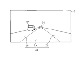
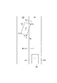
- FIG. 2 is a diagram showing an image acquired by the camera sensor.
- FIG. 3 is a diagram showing an image recognition result of the ECU.
- FIG. 4 is a diagram showing a method of calculating the left lateral distance.
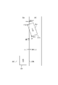
- FIG. 5 is a diagram showing the lateral distances of the other vehicles on the left and right.
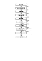
- FIG. 6 is a flowchart showing a processing procedure of ACC control according to the first embodiment.
- FIG. 7 is a diagram showing an example of position detection based on a lateral distance.
- FIG. 1 is an overall configuration diagram of the driving support system.
- FIG. 2 is a diagram showing an image acquired by the camera sensor.
- FIG. 3 is a diagram showing an image recognition result of the ECU.
- FIG. 4 is a diagram showing a method of calculating the left lateral distance.
- FIG. 5 is a diagram showing the lateral distances of the other vehicles on the left and right.
- FIG. 6 is
- the ECU 10 recognizes the lane marking based on the change in brightness on the image G. Specifically, the ECU 10 extracts a change point of the contrast (edge strength) between the dividing line dividing the lane and the road surface as an edge candidate point. Then, the candidate line of the lane marking is extracted from the series of the extracted edge candidate points.
- the ECU 10 performs driving support control based on the detection information.
- ACC Adaptive Cruise Control
- PCS PreCrush Safety
- the accelerator device 31 is an engine or a motor as a vehicle power source, and applies a driving force to the own vehicle by a driver's accelerator operation or a control command from the ECU 10.
- the brake device 32 is provided on each wheel and applies a braking force to the own vehicle by a driver's brake operation or a control command from the ECU 10.
- the alarm device 33 notifies the driver, for example, that there is a possibility of collision with another vehicle by a control command from the ECU 10.
- the ECU 10 may control an actuator that drives a steering wheel, a seat belt, or the like, in addition to controlling the brake device 32 and the alarm device 33.
- the ECU 10 acquires distance information from the own vehicle 50 for each end P1 to P3 of the other vehicle 52. For example, the ECU 10 uses the lower end of the image as a reference position in the vertical direction of the image G, calculates the vertical length from the lower end of the image to each end P1 to P3, and based on the vertical length, the ECU 10. The distance from each end P1 to P3 is calculated as the image distance.
- the image distances of the ends P1 to P3 calculated based on the image G include an error. Therefore, it is desirable to correct the lateral distances WL1 to WL3 calculated using the image distance by using the detection information of the radar sensor 22. In this case, it is preferable that the lateral distances WL1 to WL3 are corrected based on the difference between the image distances from the ends P1 to P3 and the measured distances measured by the radar sensor 22.
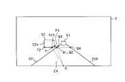
- FIG. 5 shows the left lateral distances WL1 to WL3 calculated for the other vehicle 52 traveling in the left adjacent lane ZB and the right lateral distances WR1 to WR3 calculated for the other vehicle 53 traveling in the right adjacent lane ZC. It is a figure.
- the values of the right lateral distances WR1 to WR3 are calculated, for example, with the own lane ZA side as the negative side with respect to the right side division line SSR and the anti-own lane side as the positive side with respect to the right side division line SSR.
- the ECU 10 determines whether or not an interruption has occurred according to the position of each end of the other vehicles 52 and 53 with respect to the respective lanes SSL and SSR. .. Specifically, the ECU 10 determines that the other vehicle 52 is traveling in the left adjacent lane ZB when the left lateral distances WL1 to WL3 are all positive values for the other vehicle 52 in the left adjacent lane ZB. From this state, when at least one of the left lateral distances WL1 to WL3 shifts to a negative value, it is determined that the other vehicle 52 interrupts the own lane ZA.
- the other vehicle 52 moves to the own lane ZA based on the fact that the state continues for a predetermined time. It is determined that the interruption has occurred. Specifically, when at least one of the left lateral distances WL1 to WL3 shifts to a negative value, the count unit C measures the duration, and the measurement time (count value j) by the count unit C is a predetermined value. Based on the above, it is determined that the other vehicle 52 is the preceding vehicle under ACC control. The same applies to the other vehicle 53.
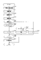
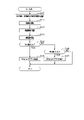
- step S11 the angle width ⁇ at each end of each of the other vehicles 52 and 53 is calculated.
- each end portion P1 to P3 which is a predetermined portion of the other vehicle 52 and each boundary point Q1 to Q3 on the left side division line SSL
- the angle widths ⁇ L1 to ⁇ l3 at each end P1 to P3 are calculated.
- the left side division line SSL is recognized as the actual division line SS1
- the angle widths ⁇ L1 to ⁇ l3 are calculated using the boundary points Q1 to Q3 on the real division line SS1.
- step S12 distance information is acquired for each end P1 to P3 of the other vehicle 52 and each end P11 to P13 of the other vehicle 53.
- This distance information includes the image distance obtained from the image G and the measured distance measured by the radar sensor 22.
- each is on the condition that the difference between the distance difference ⁇ W and the lane width Wrn is within a predetermined range, that is, on the condition that the recognition results of the respective lane markings SSL and SSR are determined to be reliable.
- Interrupt determination (preceding vehicle determination) is performed based on the lateral distances WL1 to WL3 and WR1 to WR3. Therefore, if it is determined in step S14 that there is reliability, the process proceeds to step S15, and subsequent interrupt determination is performed. On the other hand, if it is determined in step S14 that there is no reliability, the process proceeds to step S19. In step S19, the count value j of the count unit C used for the interrupt determination is reset.
- the other vehicle 53 has a negative of the right lateral distances WR1 to WR3 of the ends P11 to P13 calculated based on the right lane marking SSR. Determine if there is a value. In this case, if the right lateral distances WR1 to WR3 are all positive values, step S15 is negatively determined, and if at least one of the right lateral distances WR1 to WR3 is a negative value, step S15 is positively determined. ..
- step S16 a predetermined number (for example, 2) is added to the count value j of the counting unit C, and in step S18, a number smaller than the predetermined number (for example, 1) is added to the count value j of the counting unit C. It is also possible to configure it to add.
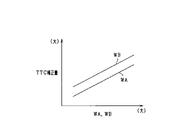
- step S35 for the ends of the other vehicles 52 and 53 determined to have entered the own lane ZA, the straight line distance from the own vehicle 50 is divided by the relative speed of the other vehicles 52 and 53 with respect to the own vehicle 50. Calculate TTC.
- step S36 the TTC of each of the other vehicles 52 and 53 is compared with a predetermined threshold value, and it is determined whether or not to operate the brake device 32 or the alarm device 33. Then, when the affirmative determination is made in step S36, the process proceeds to step S37, and the brake device 32 and the alarm device 33 are activated in order to avoid a collision with any other vehicle to be controlled.
- the distance difference ⁇ W of the lateral distances WL1 and WL4 of the boundary points Q1 and Q4 on the left and right dividing lines SSL and SSR, and the lane width Wrn (actual vehicle) of the own lane ZA determined in advance.
- the preceding vehicle is determined based on each lateral distance on condition that the difference from the line width) is within a predetermined range. As a result, it is possible to improve the accuracy when determining the other vehicles 52 and 53 as the preceding vehicle.
- step S34 it is determined whether or not the oncoming vehicle 54 is in the own lane ZA based on the lateral distances WR21 and WR22 of the respective ends P21 and P22 of the oncoming vehicle 54.
- the oncoming vehicle 54 moves from the state of being in the own lane ZA to the right adjacent lane ZC, the rear portion of the vehicle moves to the right adjacent lane ZC after the front portion of the oncoming vehicle 54.
- the oncoming vehicle 54 is in the own lane ZA, whether the lateral distance WR21 of the right front end portion P21 of the oncoming vehicle 54 and the lateral distance WR22 of the right rear end portion P22 both have negative values.
- the rear end of the other vehicle 53 on the own lane ZA side is the own vehicle. It may be in front of 50.
- the lateral distance W is calculated from the position of the lateral end portion on the own vehicle side on the front surface of the oncoming vehicle 54 and the position of the rear end portion on the side surface of the oncoming vehicle 54 on the own vehicle side, and the lateral distance W is set to the lateral distance W. Based on this, PCS control for the oncoming vehicle 54 is performed. As a result, the possibility of collision with the oncoming vehicle 54 can be reduced as compared with the case where the PCS control is performed based on the recognition result of the front surface of the oncoming vehicle 54.
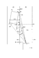
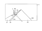
- the ECU 10 has an object point P31 indicating a predetermined portion of the object X (for example, a right lower end portion) on the same line extending in the vehicle width direction of the own vehicle, a boundary point QA on the left division line SSL, and a boundary division.
- the boundary point QB on the road surface projection line of the object BD is calculated, and the angle width ⁇ with respect to the origin O is calculated for the object point P31 and the respective boundary points QA and QB.
- the ECU 10 calculates the lateral distance W between the object X and the division lines SL and SSR based on the angle width ⁇ and the distance information to the object point P31, and also determines the object X and the boundary partition BD. The lateral distance W between them is calculated.
- step S43 the lateral distance W is calculated for the object X based on the angle width ⁇ and the distance information. Specifically, for the object point P31, the lateral distance WA with the boundary point QA on the boundary line SSL and SSR and the lateral distance WB with the boundary point QB on the boundary partition BD (road surface projection line) are calculated. ..
Landscapes
- Engineering & Computer Science (AREA)
- Transportation (AREA)
- Mechanical Engineering (AREA)
- Automation & Control Theory (AREA)
- Physics & Mathematics (AREA)
- General Physics & Mathematics (AREA)
- Multimedia (AREA)
- Theoretical Computer Science (AREA)
- Chemical & Material Sciences (AREA)
- Combustion & Propulsion (AREA)
- Human Computer Interaction (AREA)
- Traffic Control Systems (AREA)
- Control Of Driving Devices And Active Controlling Of Vehicle (AREA)
Priority Applications (1)
| Application Number | Priority Date | Filing Date | Title |
|---|---|---|---|
| US18/319,315 US12337834B2 (en) | 2020-11-19 | 2023-05-17 | Traveling support device |
Applications Claiming Priority (2)
| Application Number | Priority Date | Filing Date | Title |
|---|---|---|---|
| JP2020192851A JP7331824B2 (ja) | 2020-11-19 | 2020-11-19 | 走行支援装置 |
| JP2020-192851 | 2020-11-19 |
Related Child Applications (1)
| Application Number | Title | Priority Date | Filing Date |
|---|---|---|---|
| US18/319,315 Continuation US12337834B2 (en) | 2020-11-19 | 2023-05-17 | Traveling support device |
Publications (1)
| Publication Number | Publication Date |
|---|---|
| WO2022107549A1 true WO2022107549A1 (ja) | 2022-05-27 |
Family
ID=81708990
Family Applications (1)
| Application Number | Title | Priority Date | Filing Date |
|---|---|---|---|
| PCT/JP2021/039101 Ceased WO2022107549A1 (ja) | 2020-11-19 | 2021-10-22 | 走行支援装置 |
Country Status (3)
| Country | Link |
|---|---|
| US (1) | US12337834B2 (enExample) |
| JP (1) | JP7331824B2 (enExample) |
| WO (1) | WO2022107549A1 (enExample) |
Families Citing this family (6)
| Publication number | Priority date | Publication date | Assignee | Title |
|---|---|---|---|---|
| JP7653463B2 (ja) * | 2023-03-24 | 2025-03-28 | 本田技研工業株式会社 | 制御装置 |
| US12423864B2 (en) | 2023-03-31 | 2025-09-23 | Geotab Inc. | Systems for detecting vehicle following distance |
| US12456305B2 (en) | 2023-03-31 | 2025-10-28 | Geotab Inc. | Systems and methods for identifying tailgating |
| US11989949B1 (en) * | 2023-03-31 | 2024-05-21 | Geotab Inc. | Systems for detecting vehicle following distance |
| US20250178606A1 (en) * | 2023-12-05 | 2025-06-05 | Ford Global Technologies, Llc | Vehicle pass maneuvering |
| JP2025142763A (ja) * | 2024-03-18 | 2025-10-01 | 本田技研工業株式会社 | 制御装置、その制御方法、車両、及びプログラム。 |
Citations (3)
| Publication number | Priority date | Publication date | Assignee | Title |
|---|---|---|---|---|
| JP2015225546A (ja) * | 2014-05-28 | 2015-12-14 | 本田技研工業株式会社 | 物体検出装置、運転支援装置、物体検出方法、および物体検出プログラム |
| US10037472B1 (en) * | 2017-03-21 | 2018-07-31 | Delphi Technologies, Inc. | Automated vehicle object detection system with camera image and radar data fusion |
| JP2019217846A (ja) * | 2018-06-18 | 2019-12-26 | 本田技研工業株式会社 | 車両制御装置、車両制御方法およびプログラム |
Family Cites Families (4)
| Publication number | Priority date | Publication date | Assignee | Title |
|---|---|---|---|---|
| US6751747B2 (en) * | 2000-05-02 | 2004-06-15 | Nortel Networks Limited | System, device, and method for detecting and recovering from failures in a multicast communication system |
| JP5969534B2 (ja) | 2014-04-21 | 2016-08-17 | 株式会社デンソー | 走行支援装置 |
| JP7163589B2 (ja) * | 2018-02-14 | 2022-11-01 | 株式会社デンソー | 運転支援装置 |
| US11845439B2 (en) * | 2021-09-29 | 2023-12-19 | Canoo Technologies Inc. | Prediction of target object's behavior based on world and image frames |
-
2020
- 2020-11-19 JP JP2020192851A patent/JP7331824B2/ja active Active
-
2021
- 2021-10-22 WO PCT/JP2021/039101 patent/WO2022107549A1/ja not_active Ceased
-
2023
- 2023-05-17 US US18/319,315 patent/US12337834B2/en active Active
Patent Citations (3)
| Publication number | Priority date | Publication date | Assignee | Title |
|---|---|---|---|---|
| JP2015225546A (ja) * | 2014-05-28 | 2015-12-14 | 本田技研工業株式会社 | 物体検出装置、運転支援装置、物体検出方法、および物体検出プログラム |
| US10037472B1 (en) * | 2017-03-21 | 2018-07-31 | Delphi Technologies, Inc. | Automated vehicle object detection system with camera image and radar data fusion |
| JP2019217846A (ja) * | 2018-06-18 | 2019-12-26 | 本田技研工業株式会社 | 車両制御装置、車両制御方法およびプログラム |
Also Published As
| Publication number | Publication date |
|---|---|
| US12337834B2 (en) | 2025-06-24 |
| JP2022081350A (ja) | 2022-05-31 |
| US20230286498A1 (en) | 2023-09-14 |
| JP7331824B2 (ja) | 2023-08-23 |
Similar Documents
| Publication | Publication Date | Title |
|---|---|---|
| JP7331824B2 (ja) | 走行支援装置 | |
| JP6729282B2 (ja) | 車両制御装置 | |
| US10384681B2 (en) | Vehicle cruise control device and cruise control method | |
| US10486698B2 (en) | Vehicle cruise control device and cruise control method | |
| CN109204311B (zh) | 一种汽车速度控制方法和装置 | |
| JP6614108B2 (ja) | 車両制御装置、車両制御方法 | |
| WO2018003529A1 (ja) | 車両制御装置及び車両制御方法 | |
| WO2017170766A1 (ja) | 走行支援装置 | |
| US11180141B2 (en) | Vehicle control system | |
| JP6497284B2 (ja) | 車両制御装置、及び車両制御方法 | |
| WO2018003528A1 (ja) | 車両制御装置及び車両制御方法 | |
| US12275398B2 (en) | Vehicle drive assist apparatus | |
| WO2018030159A1 (ja) | 認識装置、及び、認識方法 | |
| JP6535537B2 (ja) | 車両の運転支援装置 | |
| CN110614997B (zh) | 车辆控制装置、车辆控制方法和记录介质 | |
| WO2020158508A1 (ja) | 物体判定装置 | |
| JP6733616B2 (ja) | 車両制御装置 | |
| JP7158183B2 (ja) | 車両制御装置、車両制御方法およびプログラム | |
| JP7458428B2 (ja) | 経路生成装置 | |
| KR20220093761A (ko) | 차량 주행 제어 시스템 및 방법 | |
| US20230365126A1 (en) | Vehicle and method of controlling the same | |
| JP7563330B2 (ja) | 駐車支援装置及びプログラム | |
| US12475711B2 (en) | Object detection device | |
| JP7561098B2 (ja) | 車両制御装置及びプログラム | |
| JP2022050966A (ja) | 物体検出装置 |
Legal Events
| Date | Code | Title | Description |
|---|---|---|---|
| 121 | Ep: the epo has been informed by wipo that ep was designated in this application |
Ref document number: 21894423 Country of ref document: EP Kind code of ref document: A1 |
|
| NENP | Non-entry into the national phase |
Ref country code: DE |
|
| 122 | Ep: pct application non-entry in european phase |
Ref document number: 21894423 Country of ref document: EP Kind code of ref document: A1 |