WO2022107549A1 - Traveling support device - Google Patents
Traveling support device Download PDFInfo
- Publication number
- WO2022107549A1 WO2022107549A1 PCT/JP2021/039101 JP2021039101W WO2022107549A1 WO 2022107549 A1 WO2022107549 A1 WO 2022107549A1 JP 2021039101 W JP2021039101 W JP 2021039101W WO 2022107549 A1 WO2022107549 A1 WO 2022107549A1
- Authority
- WO
- WIPO (PCT)
- Prior art keywords
- vehicle
- lateral distance
- lane
- traveling
- angle width
- Prior art date
Links
- 238000004364 calculation method Methods 0.000 claims abstract description 23
- 230000000116 mitigating effect Effects 0.000 claims description 5
- 230000007704 transition Effects 0.000 claims 1
- 238000003384 imaging method Methods 0.000 abstract description 3
- 238000000034 method Methods 0.000 description 34
- 230000008569 process Effects 0.000 description 21
- 238000010586 diagram Methods 0.000 description 12
- 238000005192 partition Methods 0.000 description 10
- 238000001514 detection method Methods 0.000 description 9
- 238000012545 processing Methods 0.000 description 9
- 238000012937 correction Methods 0.000 description 7
- 230000008859 change Effects 0.000 description 3
- 230000000694 effects Effects 0.000 description 3
- 238000004590 computer program Methods 0.000 description 2
- 230000006870 function Effects 0.000 description 2
- 230000003044 adaptive effect Effects 0.000 description 1
- 230000005540 biological transmission Effects 0.000 description 1
- 238000004891 communication Methods 0.000 description 1
- 230000006866 deterioration Effects 0.000 description 1
- 239000000284 extract Substances 0.000 description 1
- 230000006872 improvement Effects 0.000 description 1
- 238000005259 measurement Methods 0.000 description 1
- 230000003287 optical effect Effects 0.000 description 1
- 238000005457 optimization Methods 0.000 description 1
- 230000011218 segmentation Effects 0.000 description 1
- 230000001629 suppression Effects 0.000 description 1
Images


Classifications
-
- B—PERFORMING OPERATIONS; TRANSPORTING
- B60—VEHICLES IN GENERAL
- B60W—CONJOINT CONTROL OF VEHICLE SUB-UNITS OF DIFFERENT TYPE OR DIFFERENT FUNCTION; CONTROL SYSTEMS SPECIALLY ADAPTED FOR HYBRID VEHICLES; ROAD VEHICLE DRIVE CONTROL SYSTEMS FOR PURPOSES NOT RELATED TO THE CONTROL OF A PARTICULAR SUB-UNIT
- B60W30/00—Purposes of road vehicle drive control systems not related to the control of a particular sub-unit, e.g. of systems using conjoint control of vehicle sub-units, or advanced driver assistance systems for ensuring comfort, stability and safety or drive control systems for propelling or retarding the vehicle
- B60W30/08—Active safety systems predicting or avoiding probable or impending collision or attempting to minimise its consequences
- B60W30/09—Taking automatic action to avoid collision, e.g. braking and steering
-
- B—PERFORMING OPERATIONS; TRANSPORTING
- B60—VEHICLES IN GENERAL
- B60W—CONJOINT CONTROL OF VEHICLE SUB-UNITS OF DIFFERENT TYPE OR DIFFERENT FUNCTION; CONTROL SYSTEMS SPECIALLY ADAPTED FOR HYBRID VEHICLES; ROAD VEHICLE DRIVE CONTROL SYSTEMS FOR PURPOSES NOT RELATED TO THE CONTROL OF A PARTICULAR SUB-UNIT
- B60W10/00—Conjoint control of vehicle sub-units of different type or different function
- B60W10/04—Conjoint control of vehicle sub-units of different type or different function including control of propulsion units
-
- B—PERFORMING OPERATIONS; TRANSPORTING
- B60—VEHICLES IN GENERAL
- B60W—CONJOINT CONTROL OF VEHICLE SUB-UNITS OF DIFFERENT TYPE OR DIFFERENT FUNCTION; CONTROL SYSTEMS SPECIALLY ADAPTED FOR HYBRID VEHICLES; ROAD VEHICLE DRIVE CONTROL SYSTEMS FOR PURPOSES NOT RELATED TO THE CONTROL OF A PARTICULAR SUB-UNIT
- B60W10/00—Conjoint control of vehicle sub-units of different type or different function
- B60W10/18—Conjoint control of vehicle sub-units of different type or different function including control of braking systems
- B60W10/184—Conjoint control of vehicle sub-units of different type or different function including control of braking systems with wheel brakes
-
- B—PERFORMING OPERATIONS; TRANSPORTING
- B60—VEHICLES IN GENERAL
- B60W—CONJOINT CONTROL OF VEHICLE SUB-UNITS OF DIFFERENT TYPE OR DIFFERENT FUNCTION; CONTROL SYSTEMS SPECIALLY ADAPTED FOR HYBRID VEHICLES; ROAD VEHICLE DRIVE CONTROL SYSTEMS FOR PURPOSES NOT RELATED TO THE CONTROL OF A PARTICULAR SUB-UNIT
- B60W30/00—Purposes of road vehicle drive control systems not related to the control of a particular sub-unit, e.g. of systems using conjoint control of vehicle sub-units, or advanced driver assistance systems for ensuring comfort, stability and safety or drive control systems for propelling or retarding the vehicle
- B60W30/14—Adaptive cruise control
- B60W30/16—Control of distance between vehicles, e.g. keeping a distance to preceding vehicle
-
- B—PERFORMING OPERATIONS; TRANSPORTING
- B60—VEHICLES IN GENERAL
- B60W—CONJOINT CONTROL OF VEHICLE SUB-UNITS OF DIFFERENT TYPE OR DIFFERENT FUNCTION; CONTROL SYSTEMS SPECIALLY ADAPTED FOR HYBRID VEHICLES; ROAD VEHICLE DRIVE CONTROL SYSTEMS FOR PURPOSES NOT RELATED TO THE CONTROL OF A PARTICULAR SUB-UNIT
- B60W50/00—Details of control systems for road vehicle drive control not related to the control of a particular sub-unit, e.g. process diagnostic or vehicle driver interfaces
- B60W50/08—Interaction between the driver and the control system
- B60W50/14—Means for informing the driver, warning the driver or prompting a driver intervention
-
- G—PHYSICS
- G06—COMPUTING; CALCULATING OR COUNTING
- G06V—IMAGE OR VIDEO RECOGNITION OR UNDERSTANDING
- G06V20/00—Scenes; Scene-specific elements
- G06V20/50—Context or environment of the image
- G06V20/56—Context or environment of the image exterior to a vehicle by using sensors mounted on the vehicle
- G06V20/58—Recognition of moving objects or obstacles, e.g. vehicles or pedestrians; Recognition of traffic objects, e.g. traffic signs, traffic lights or roads
-
- G—PHYSICS
- G06—COMPUTING; CALCULATING OR COUNTING
- G06V—IMAGE OR VIDEO RECOGNITION OR UNDERSTANDING
- G06V20/00—Scenes; Scene-specific elements
- G06V20/50—Context or environment of the image
- G06V20/56—Context or environment of the image exterior to a vehicle by using sensors mounted on the vehicle
- G06V20/588—Recognition of the road, e.g. of lane markings; Recognition of the vehicle driving pattern in relation to the road
-
- G—PHYSICS
- G08—SIGNALLING
- G08G—TRAFFIC CONTROL SYSTEMS
- G08G1/00—Traffic control systems for road vehicles
- G08G1/16—Anti-collision systems
-
- B—PERFORMING OPERATIONS; TRANSPORTING
- B60—VEHICLES IN GENERAL
- B60W—CONJOINT CONTROL OF VEHICLE SUB-UNITS OF DIFFERENT TYPE OR DIFFERENT FUNCTION; CONTROL SYSTEMS SPECIALLY ADAPTED FOR HYBRID VEHICLES; ROAD VEHICLE DRIVE CONTROL SYSTEMS FOR PURPOSES NOT RELATED TO THE CONTROL OF A PARTICULAR SUB-UNIT
- B60W2420/00—Indexing codes relating to the type of sensors based on the principle of their operation
- B60W2420/40—Photo or light sensitive means, e.g. infrared sensors
- B60W2420/403—Image sensing, e.g. optical camera
-
- B—PERFORMING OPERATIONS; TRANSPORTING
- B60—VEHICLES IN GENERAL
- B60W—CONJOINT CONTROL OF VEHICLE SUB-UNITS OF DIFFERENT TYPE OR DIFFERENT FUNCTION; CONTROL SYSTEMS SPECIALLY ADAPTED FOR HYBRID VEHICLES; ROAD VEHICLE DRIVE CONTROL SYSTEMS FOR PURPOSES NOT RELATED TO THE CONTROL OF A PARTICULAR SUB-UNIT
- B60W2552/00—Input parameters relating to infrastructure
- B60W2552/10—Number of lanes
-
- B—PERFORMING OPERATIONS; TRANSPORTING
- B60—VEHICLES IN GENERAL
- B60W—CONJOINT CONTROL OF VEHICLE SUB-UNITS OF DIFFERENT TYPE OR DIFFERENT FUNCTION; CONTROL SYSTEMS SPECIALLY ADAPTED FOR HYBRID VEHICLES; ROAD VEHICLE DRIVE CONTROL SYSTEMS FOR PURPOSES NOT RELATED TO THE CONTROL OF A PARTICULAR SUB-UNIT
- B60W2552/00—Input parameters relating to infrastructure
- B60W2552/53—Road markings, e.g. lane marker or crosswalk
-
- B—PERFORMING OPERATIONS; TRANSPORTING
- B60—VEHICLES IN GENERAL
- B60W—CONJOINT CONTROL OF VEHICLE SUB-UNITS OF DIFFERENT TYPE OR DIFFERENT FUNCTION; CONTROL SYSTEMS SPECIALLY ADAPTED FOR HYBRID VEHICLES; ROAD VEHICLE DRIVE CONTROL SYSTEMS FOR PURPOSES NOT RELATED TO THE CONTROL OF A PARTICULAR SUB-UNIT
- B60W2554/00—Input parameters relating to objects
- B60W2554/40—Dynamic objects, e.g. animals, windblown objects
- B60W2554/402—Type
- B60W2554/4029—Pedestrians
-
- B—PERFORMING OPERATIONS; TRANSPORTING
- B60—VEHICLES IN GENERAL
- B60W—CONJOINT CONTROL OF VEHICLE SUB-UNITS OF DIFFERENT TYPE OR DIFFERENT FUNCTION; CONTROL SYSTEMS SPECIALLY ADAPTED FOR HYBRID VEHICLES; ROAD VEHICLE DRIVE CONTROL SYSTEMS FOR PURPOSES NOT RELATED TO THE CONTROL OF A PARTICULAR SUB-UNIT
- B60W2554/00—Input parameters relating to objects
- B60W2554/40—Dynamic objects, e.g. animals, windblown objects
- B60W2554/404—Characteristics
- B60W2554/4045—Intention, e.g. lane change or imminent movement
-
- B—PERFORMING OPERATIONS; TRANSPORTING
- B60—VEHICLES IN GENERAL
- B60W—CONJOINT CONTROL OF VEHICLE SUB-UNITS OF DIFFERENT TYPE OR DIFFERENT FUNCTION; CONTROL SYSTEMS SPECIALLY ADAPTED FOR HYBRID VEHICLES; ROAD VEHICLE DRIVE CONTROL SYSTEMS FOR PURPOSES NOT RELATED TO THE CONTROL OF A PARTICULAR SUB-UNIT
- B60W2554/00—Input parameters relating to objects
- B60W2554/80—Spatial relation or speed relative to objects
- B60W2554/801—Lateral distance
-
- B—PERFORMING OPERATIONS; TRANSPORTING
- B60—VEHICLES IN GENERAL
- B60W—CONJOINT CONTROL OF VEHICLE SUB-UNITS OF DIFFERENT TYPE OR DIFFERENT FUNCTION; CONTROL SYSTEMS SPECIALLY ADAPTED FOR HYBRID VEHICLES; ROAD VEHICLE DRIVE CONTROL SYSTEMS FOR PURPOSES NOT RELATED TO THE CONTROL OF A PARTICULAR SUB-UNIT
- B60W2554/00—Input parameters relating to objects
- B60W2554/80—Spatial relation or speed relative to objects
- B60W2554/802—Longitudinal distance
-
- B—PERFORMING OPERATIONS; TRANSPORTING
- B60—VEHICLES IN GENERAL
- B60W—CONJOINT CONTROL OF VEHICLE SUB-UNITS OF DIFFERENT TYPE OR DIFFERENT FUNCTION; CONTROL SYSTEMS SPECIALLY ADAPTED FOR HYBRID VEHICLES; ROAD VEHICLE DRIVE CONTROL SYSTEMS FOR PURPOSES NOT RELATED TO THE CONTROL OF A PARTICULAR SUB-UNIT
- B60W2554/00—Input parameters relating to objects
- B60W2554/80—Spatial relation or speed relative to objects
- B60W2554/806—Relative heading
Definitions
- the present disclosure is applied to a vehicle equipped with an image pickup device that images the surroundings of the own vehicle, and is a travel support device that controls the travel support of the own vehicle based on the image captured by the image pickup device.
- a recognition unit that recognizes a front object existing in front of the own vehicle in the traveling direction and the left and right boundary portions of the road on which the own vehicle travels, and in the image, the vehicle width direction of the own vehicle.
- An object point indicating a predetermined part of the front object and a boundary point on the boundary portion are calculated on the same line extending to the above, and the angle between the object point and the boundary point with respect to the origin defined in the image.
- FIG. 1 is an overall configuration diagram of the driving support system.
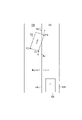
- FIG. 2 is a diagram showing an image acquired by the camera sensor.
- FIG. 3 is a diagram showing an image recognition result of the ECU.
- FIG. 4 is a diagram showing a method of calculating the left lateral distance.
- FIG. 5 is a diagram showing the lateral distances of the other vehicles on the left and right.
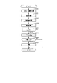
- FIG. 6 is a flowchart showing a processing procedure of ACC control according to the first embodiment.
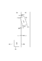
- FIG. 7 is a diagram showing an example of position detection based on a lateral distance.
- FIG. 1 is an overall configuration diagram of the driving support system.
- FIG. 2 is a diagram showing an image acquired by the camera sensor.
- FIG. 3 is a diagram showing an image recognition result of the ECU.
- FIG. 4 is a diagram showing a method of calculating the left lateral distance.
- FIG. 5 is a diagram showing the lateral distances of the other vehicles on the left and right.
- FIG. 6 is
- the ECU 10 recognizes the lane marking based on the change in brightness on the image G. Specifically, the ECU 10 extracts a change point of the contrast (edge strength) between the dividing line dividing the lane and the road surface as an edge candidate point. Then, the candidate line of the lane marking is extracted from the series of the extracted edge candidate points.
- the ECU 10 performs driving support control based on the detection information.
- ACC Adaptive Cruise Control
- PCS PreCrush Safety
- the accelerator device 31 is an engine or a motor as a vehicle power source, and applies a driving force to the own vehicle by a driver's accelerator operation or a control command from the ECU 10.
- the brake device 32 is provided on each wheel and applies a braking force to the own vehicle by a driver's brake operation or a control command from the ECU 10.
- the alarm device 33 notifies the driver, for example, that there is a possibility of collision with another vehicle by a control command from the ECU 10.
- the ECU 10 may control an actuator that drives a steering wheel, a seat belt, or the like, in addition to controlling the brake device 32 and the alarm device 33.
- the ECU 10 acquires distance information from the own vehicle 50 for each end P1 to P3 of the other vehicle 52. For example, the ECU 10 uses the lower end of the image as a reference position in the vertical direction of the image G, calculates the vertical length from the lower end of the image to each end P1 to P3, and based on the vertical length, the ECU 10. The distance from each end P1 to P3 is calculated as the image distance.
- the image distances of the ends P1 to P3 calculated based on the image G include an error. Therefore, it is desirable to correct the lateral distances WL1 to WL3 calculated using the image distance by using the detection information of the radar sensor 22. In this case, it is preferable that the lateral distances WL1 to WL3 are corrected based on the difference between the image distances from the ends P1 to P3 and the measured distances measured by the radar sensor 22.
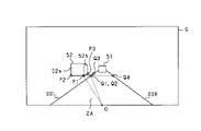
- FIG. 5 shows the left lateral distances WL1 to WL3 calculated for the other vehicle 52 traveling in the left adjacent lane ZB and the right lateral distances WR1 to WR3 calculated for the other vehicle 53 traveling in the right adjacent lane ZC. It is a figure.
- the values of the right lateral distances WR1 to WR3 are calculated, for example, with the own lane ZA side as the negative side with respect to the right side division line SSR and the anti-own lane side as the positive side with respect to the right side division line SSR.
- the ECU 10 determines whether or not an interruption has occurred according to the position of each end of the other vehicles 52 and 53 with respect to the respective lanes SSL and SSR. .. Specifically, the ECU 10 determines that the other vehicle 52 is traveling in the left adjacent lane ZB when the left lateral distances WL1 to WL3 are all positive values for the other vehicle 52 in the left adjacent lane ZB. From this state, when at least one of the left lateral distances WL1 to WL3 shifts to a negative value, it is determined that the other vehicle 52 interrupts the own lane ZA.
- the other vehicle 52 moves to the own lane ZA based on the fact that the state continues for a predetermined time. It is determined that the interruption has occurred. Specifically, when at least one of the left lateral distances WL1 to WL3 shifts to a negative value, the count unit C measures the duration, and the measurement time (count value j) by the count unit C is a predetermined value. Based on the above, it is determined that the other vehicle 52 is the preceding vehicle under ACC control. The same applies to the other vehicle 53.
- step S11 the angle width ⁇ at each end of each of the other vehicles 52 and 53 is calculated.
- each end portion P1 to P3 which is a predetermined portion of the other vehicle 52 and each boundary point Q1 to Q3 on the left side division line SSL
- the angle widths ⁇ L1 to ⁇ l3 at each end P1 to P3 are calculated.
- the left side division line SSL is recognized as the actual division line SS1
- the angle widths ⁇ L1 to ⁇ l3 are calculated using the boundary points Q1 to Q3 on the real division line SS1.
- step S12 distance information is acquired for each end P1 to P3 of the other vehicle 52 and each end P11 to P13 of the other vehicle 53.
- This distance information includes the image distance obtained from the image G and the measured distance measured by the radar sensor 22.
- each is on the condition that the difference between the distance difference ⁇ W and the lane width Wrn is within a predetermined range, that is, on the condition that the recognition results of the respective lane markings SSL and SSR are determined to be reliable.
- Interrupt determination (preceding vehicle determination) is performed based on the lateral distances WL1 to WL3 and WR1 to WR3. Therefore, if it is determined in step S14 that there is reliability, the process proceeds to step S15, and subsequent interrupt determination is performed. On the other hand, if it is determined in step S14 that there is no reliability, the process proceeds to step S19. In step S19, the count value j of the count unit C used for the interrupt determination is reset.
- the other vehicle 53 has a negative of the right lateral distances WR1 to WR3 of the ends P11 to P13 calculated based on the right lane marking SSR. Determine if there is a value. In this case, if the right lateral distances WR1 to WR3 are all positive values, step S15 is negatively determined, and if at least one of the right lateral distances WR1 to WR3 is a negative value, step S15 is positively determined. ..
- step S16 a predetermined number (for example, 2) is added to the count value j of the counting unit C, and in step S18, a number smaller than the predetermined number (for example, 1) is added to the count value j of the counting unit C. It is also possible to configure it to add.
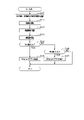
- step S35 for the ends of the other vehicles 52 and 53 determined to have entered the own lane ZA, the straight line distance from the own vehicle 50 is divided by the relative speed of the other vehicles 52 and 53 with respect to the own vehicle 50. Calculate TTC.
- step S36 the TTC of each of the other vehicles 52 and 53 is compared with a predetermined threshold value, and it is determined whether or not to operate the brake device 32 or the alarm device 33. Then, when the affirmative determination is made in step S36, the process proceeds to step S37, and the brake device 32 and the alarm device 33 are activated in order to avoid a collision with any other vehicle to be controlled.
- the distance difference ⁇ W of the lateral distances WL1 and WL4 of the boundary points Q1 and Q4 on the left and right dividing lines SSL and SSR, and the lane width Wrn (actual vehicle) of the own lane ZA determined in advance.
- the preceding vehicle is determined based on each lateral distance on condition that the difference from the line width) is within a predetermined range. As a result, it is possible to improve the accuracy when determining the other vehicles 52 and 53 as the preceding vehicle.
- step S34 it is determined whether or not the oncoming vehicle 54 is in the own lane ZA based on the lateral distances WR21 and WR22 of the respective ends P21 and P22 of the oncoming vehicle 54.
- the oncoming vehicle 54 moves from the state of being in the own lane ZA to the right adjacent lane ZC, the rear portion of the vehicle moves to the right adjacent lane ZC after the front portion of the oncoming vehicle 54.
- the oncoming vehicle 54 is in the own lane ZA, whether the lateral distance WR21 of the right front end portion P21 of the oncoming vehicle 54 and the lateral distance WR22 of the right rear end portion P22 both have negative values.
- the rear end of the other vehicle 53 on the own lane ZA side is the own vehicle. It may be in front of 50.
- the lateral distance W is calculated from the position of the lateral end portion on the own vehicle side on the front surface of the oncoming vehicle 54 and the position of the rear end portion on the side surface of the oncoming vehicle 54 on the own vehicle side, and the lateral distance W is set to the lateral distance W. Based on this, PCS control for the oncoming vehicle 54 is performed. As a result, the possibility of collision with the oncoming vehicle 54 can be reduced as compared with the case where the PCS control is performed based on the recognition result of the front surface of the oncoming vehicle 54.
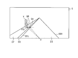
- the ECU 10 has an object point P31 indicating a predetermined portion of the object X (for example, a right lower end portion) on the same line extending in the vehicle width direction of the own vehicle, a boundary point QA on the left division line SSL, and a boundary division.
- the boundary point QB on the road surface projection line of the object BD is calculated, and the angle width ⁇ with respect to the origin O is calculated for the object point P31 and the respective boundary points QA and QB.
- the ECU 10 calculates the lateral distance W between the object X and the division lines SL and SSR based on the angle width ⁇ and the distance information to the object point P31, and also determines the object X and the boundary partition BD. The lateral distance W between them is calculated.
- step S43 the lateral distance W is calculated for the object X based on the angle width ⁇ and the distance information. Specifically, for the object point P31, the lateral distance WA with the boundary point QA on the boundary line SSL and SSR and the lateral distance WB with the boundary point QB on the boundary partition BD (road surface projection line) are calculated. ..
Abstract
This traveling support device (10) is applied to a vehicle on which an imaging device (21) is mounted and performs traveling support control of a host vehicle on the basis of an image captured by the imaging device. The traveling support device comprises: a recognition unit that recognizes, on the basis of the image, a front object present in front of the host vehicle in a traveling direction and a left/right boundary portion on a road on which the host vehicle travels; an angle width calculation unit that calculates, for the image, an object point indicating a predetermined portion and a boundary point on the boundary portion of the front object on the same line extending from the host vehicle in a vehicle width direction, and calculates, for the object point and the boundary point, an angle width using an original point determined in the image as a reference; an acquisition unit that acquires distance information up to the predetermined portion of the front object; a lateral distance calculation unit that calculates, on the basis of the angle width calculated by the angle width calculation unit and the distance information, a lateral distance that is a distance between the predetermined portion and the boundary portion of the front object in the vehicle width direction of the host vehicle; and a control unit that performs traveling support control for the front body on the basis of the lateral distance.
Description
本出願は、2020年11月19日に出願された日本出願番号2020-192851号に基づくもので、ここにその記載内容を援用する。
This application is based on Japanese Application No. 2020-192851 filed on November 19, 2020, and the contents of the description are incorporated herein by reference.
本開示は、自車両の周囲に存在する物体の位置に基づいて、自車両の走行支援制御を行う走行支援装置に関する。
The present disclosure relates to a travel support device that controls the travel support of the own vehicle based on the position of an object existing around the own vehicle.
走行支援装置として、自車両の周囲を撮像装置により撮像し、その撮像された画像に基づいて自車両の走行支援制御を行うものが知られている。例えば、特許文献1に記載された走行支援装置では、画像により自車両の走行方向前方に存在する他車両の位置が認識され、認識された他車両から自車両が走行する自車線までの距離に基づいて、自車両の走行支援制御が行われる。
As a driving support device, there is known a device that captures an image of the surroundings of the own vehicle with an image pickup device and performs driving support control of the own vehicle based on the captured image. For example, in the traveling support device described in Patent Document 1, the position of another vehicle existing in front of the traveling direction of the own vehicle is recognized by the image, and the distance from the recognized other vehicle to the own lane in which the own vehicle travels is set. Based on this, the driving support control of the own vehicle is performed.
例えば、自車線を走行する自車両において、前方を走行する他車両に対して適正な位置関係を保った状態での走行を実施するには、その他車両と自車線との位置関係を適正に把握する必要がある。この場合、他車両の位置を適正に把握できないと、その他車両に対する衝突抑制の制御や、他車両に対する追従制御が適正に実施できなくなることが懸念される。こうした問題に対処すべく、他車両の位置を適正に把握して走行支援制御を適切に実施することには、未だ改善の余地がある。
For example, in order to carry out driving in a state where the own vehicle traveling in the own lane maintains an appropriate positional relationship with other vehicles traveling in front, the positional relationship between the other vehicle and the own lane is properly grasped. There is a need to. In this case, if the position of the other vehicle cannot be properly grasped, there is a concern that the collision suppression control for the other vehicle and the follow-up control for the other vehicle cannot be properly performed. There is still room for improvement in properly grasping the positions of other vehicles and appropriately implementing driving support control in order to deal with such problems.
本開示は、上記課題に鑑みてなされたものであり、その主たる目的は、走行支援制御を適切に実施することができる走行支援装置を提供することである。
The present disclosure has been made in view of the above problems, and its main purpose is to provide a driving support device capable of appropriately implementing driving support control.
本開示は、自車両の周囲を撮像する撮像装置が搭載された車両に適用され、前記撮像装置により撮像された画像に基づいて前記自車両の走行支援制御を行う走行支援装置であって、前記画像に基づいて、前記自車両の走行方向前方に存在する前方物体と、前記自車両が走行する道路の左右の境界部とを認識する認識部と、前記画像において、前記自車両の車幅方向に延びる同一線上で前記前方物体の所定部位を示す物体点と前記境界部上の境界点とを算出するとともに、それら物体点と境界点とについて、前記画像に定められた原点を基準とする角度幅を算出する角度幅算出部と、前記前方物体における前記所定部位までの距離情報を取得する取得部と、前記角度幅算出部により算出された角度幅と前記距離情報とに基づいて、前記前方物体における前記所定部位と前記境界部との間において前記自車両の車幅方向の距離である横距離を算出する横距離算出部と、前記横距離に基づいて、前記前方物体に対する走行支援制御を実施する制御部と、を備える。
The present disclosure is applied to a vehicle equipped with an image pickup device that images the surroundings of the own vehicle, and is a travel support device that controls the travel support of the own vehicle based on the image captured by the image pickup device. Based on the image, a recognition unit that recognizes a front object existing in front of the own vehicle in the traveling direction and the left and right boundary portions of the road on which the own vehicle travels, and in the image, the vehicle width direction of the own vehicle. An object point indicating a predetermined part of the front object and a boundary point on the boundary portion are calculated on the same line extending to the above, and the angle between the object point and the boundary point with respect to the origin defined in the image. The front based on the angle width calculation unit for calculating the width, the acquisition unit for acquiring the distance information to the predetermined portion of the front object, the angle width calculated by the angle width calculation unit, and the distance information. A lateral distance calculation unit that calculates a lateral distance that is a distance in the vehicle width direction of the own vehicle between the predetermined portion and the boundary portion of the object, and a traveling support control for the front object based on the lateral distance. It is provided with a control unit to be implemented.
画像に基づいて前方物体と道路の境界部とが認識され、認識された前方物体及び境界部の位置関係に基づいて走行支援制御が行われる場合、道路に対する前方物体の位置が適正に検出されないと、走行支援制御が適切に行われないことが懸念される。この点、本開示では、画像において、自車両の車幅方向に延びる同一線上で前方物体の所定部位を示す物体点と境界部上の境界点とが算出されるとともに、それら物体点と境界点とについて、画像の原点を基準とする角度幅が算出される。また、その角度幅と、前方物体の所定部位までの距離情報とに基づいて、前方物体の所定部位と境界部との間における自車両の車幅方向の距離である横距離が算出される。そして、その横距離に基づいて、前方物体に対する走行支援制御が実施される。
When the front object and the boundary portion of the road are recognized based on the image and the traveling support control is performed based on the positional relationship between the recognized front object and the boundary portion, the position of the front object with respect to the road is not properly detected. , There is a concern that driving support control will not be performed properly. In this regard, in the present disclosure, in the image, an object point indicating a predetermined part of a front object on the same line extending in the vehicle width direction of the own vehicle and a boundary point on the boundary portion are calculated, and these object points and the boundary point are calculated. With respect to, the angle width with respect to the origin of the image is calculated. Further, based on the angle width and the distance information to the predetermined portion of the front object, the lateral distance, which is the distance in the vehicle width direction of the own vehicle between the predetermined portion of the front object and the boundary portion, is calculated. Then, based on the lateral distance, the traveling support control for the forward object is carried out.
上記構成によれば、前方物体について、所望の位置で道路の境界部に対する位置を適正に把握することができる。この場合、前方物体での検出すべき所定部位が走行シーン等に応じて都度変化するとしても、所望とする部位を対象にして適正な位置検出を実施することができる。これにより、前方物体の位置検出を適正に実施し、ひいては走行支援制御を適切に実施することができる。
According to the above configuration, it is possible to properly grasp the position of the front object with respect to the boundary portion of the road at a desired position. In this case, even if the predetermined portion to be detected in the front object changes each time according to the traveling scene or the like, appropriate position detection can be performed for the desired portion. As a result, the position of the forward object can be detected appropriately, and the traveling support control can be appropriately performed.
本開示についての上記目的およびその他の目的、特徴や利点は、添付の図面を参照しながら下記の詳細な記述により、より明確になる。その図面は、
図1は、走行支援システムの全体構成図であり、
図2は、カメラセンサにより取得された画像を示す図であり、
図3は、ECUの画像認識結果を示す図であり、
図4は、左側横距離の算出方法を示す図であり、
図5は、左右の他車両についての横距離を示す図であり、
図6は、第1実施形態に係るACC制御の処理手順を示すフローチャートであり、
図7は、横距離による位置検出の一例を示す図であり、
図8は、第1実施形態に係るPCS制御の処理手順を示すフローチャートであり、
図9は、第2実施形態に係る位置検出の一例を示す図であり、
図10は、第3実施形態に係る位置検出の一例を示す図であり、
図11は、第3実施形態に係る位置検出の一例を示す図であり、
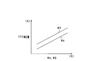
図12は、横距離とTTC補正量との関係を示す図であり、
図13は、第3施形態に係るPCS制御の処理手順を示すフローチャートである。
The above objectives and other objectives, features and advantages of the present disclosure will be further clarified by the following detailed description with reference to the accompanying drawings. The drawing is
FIG. 1 is an overall configuration diagram of the driving support system. FIG. 2 is a diagram showing an image acquired by the camera sensor. FIG. 3 is a diagram showing an image recognition result of the ECU. FIG. 4 is a diagram showing a method of calculating the left lateral distance. FIG. 5 is a diagram showing the lateral distances of the other vehicles on the left and right. FIG. 6 is a flowchart showing a processing procedure of ACC control according to the first embodiment. FIG. 7 is a diagram showing an example of position detection based on a lateral distance. FIG. 8 is a flowchart showing the processing procedure of the PCS control according to the first embodiment. FIG. 9 is a diagram showing an example of position detection according to the second embodiment. FIG. 10 is a diagram showing an example of position detection according to the third embodiment. FIG. 11 is a diagram showing an example of position detection according to the third embodiment. FIG. 12 is a diagram showing the relationship between the lateral distance and the TTC correction amount. FIG. 13 is a flowchart showing a processing procedure of PCS control according to the third embodiment.
<第1実施形態>
以下、本開示に係る走行支援装置を具体化した第1実施形態について、図面を参照しつつ説明する。本実施形態に係る走行支援システム100は、自車両に搭載され、自車両の周囲に存在する物体(車両、歩行者、路上障害物等)を検出する。 <First Embodiment>
Hereinafter, the first embodiment in which the traveling support device according to the present disclosure is embodied will be described with reference to the drawings. Thetravel support system 100 according to the present embodiment is mounted on the own vehicle and detects an object (vehicle, pedestrian, road obstacle, etc.) existing around the own vehicle.
以下、本開示に係る走行支援装置を具体化した第1実施形態について、図面を参照しつつ説明する。本実施形態に係る走行支援システム100は、自車両に搭載され、自車両の周囲に存在する物体(車両、歩行者、路上障害物等)を検出する。 <First Embodiment>
Hereinafter, the first embodiment in which the traveling support device according to the present disclosure is embodied will be described with reference to the drawings. The
図1に示すように、本実施形態に係る走行支援システム100は、走行支援装置としてのECU10と、センサ類20と、被制御装置30とを備えている。センサ類20としては、「撮像装置」としてのカメラセンサ21、レーダセンサ22が含まれる。被制御装置30としては、アクセル装置31、ブレーキ装置32及び警報装置33が含まれる。
As shown in FIG. 1, the travel support system 100 according to the present embodiment includes an ECU 10 as a travel support device, sensors 20, and a controlled device 30. The sensors 20 include a camera sensor 21 and a radar sensor 22 as an “imaging device”. The controlled device 30 includes an accelerator device 31, a brake device 32, and an alarm device 33.
カメラセンサ21は、例えば単眼カメラであり、自車両のフロントガラスの上端付近等に設置されている。カメラセンサ21は、所定時間毎に自車両の前方に存在する物体を撮像し、撮像した画像G(図2参照)を取得する。
The camera sensor 21 is, for example, a monocular camera, and is installed near the upper end of the windshield of the own vehicle. The camera sensor 21 captures an object existing in front of the own vehicle at predetermined time intervals, and acquires the captured image G (see FIG. 2).
レーダセンサ22は、自車両の周囲に探査波を送信し、その探査波の反射波を受信することで自車両の周囲に存在する物体までの距離情報を取得する測距センサであり、例えば自車両の前部においてその光軸が自車両前方を向くように取り付けられている。レーダセンサ22は、所定時間毎に自車両の前方に向かって、探査波であるミリ波帯の指向性のある電磁波を走査するとともに、物体の表面で反射された反射波を複数のアンテナにより受信することで物体までの距離、物体の方位等を距離情報として取得する。レーダセンサ22は、探査波の送信時刻と反射波の受信時刻とにより、物体までの距離を算出して取得する。また、レーダセンサ22は、複数のアンテナが受信した反射波の位相差により、物体の方位を算出して取得する。
The radar sensor 22 is a distance measuring sensor that transmits an exploration wave around the own vehicle and receives the reflected wave of the exploration wave to acquire distance information to an object existing around the own vehicle. At the front of the vehicle, the optical axis is attached so as to face the front of the vehicle. The radar sensor 22 scans a directional electromagnetic wave in the millimeter wave band, which is an exploration wave, toward the front of the own vehicle at predetermined time intervals, and receives the reflected wave reflected on the surface of the object by a plurality of antennas. By doing so, the distance to the object, the orientation of the object, etc. are acquired as distance information. The radar sensor 22 calculates and acquires the distance to the object based on the transmission time of the exploration wave and the reception time of the reflected wave. Further, the radar sensor 22 calculates and acquires the direction of the object based on the phase difference of the reflected waves received by the plurality of antennas.
ECU10は、CPU,ROM,RAM,フラッシュメモリ等からなる周知のマイクロコンピュータを備えた制御装置である。ECU10は、カメラセンサ21から取得される画像Gと、レーダセンサ22から取得される距離情報とをそれぞれ取得する。
The ECU 10 is a control device equipped with a well-known microcomputer including a CPU, ROM, RAM, flash memory, and the like. The ECU 10 acquires the image G acquired from the camera sensor 21 and the distance information acquired from the radar sensor 22, respectively.
ECU10は、カメラセンサ21により取得される画像Gに対して、テンプレートマッチングのような画像認識処理を行うことにより、画像G内に存在する物体とその種類(車両、歩行者、路上障害物等)を認識する。本実施形態では、各物体の種類を特定するためのテンプレートとして、物体ごとの特徴を示す画像パターンである複数の辞書が記憶されている。辞書としては、物体全体の特徴をパターン化した全身辞書と、物体の部分的な特徴をパターン化した半身辞書とが記憶されている。
The ECU 10 performs image recognition processing such as template matching on the image G acquired by the camera sensor 21, so that the objects existing in the image G and their types (vehicles, pedestrians, road obstacles, etc.) Recognize. In this embodiment, as a template for specifying the type of each object, a plurality of dictionaries which are image patterns showing the characteristics of each object are stored. As the dictionary, a full-body dictionary in which the characteristics of the entire object are patterned and a half-body dictionary in which the characteristics of a partial object are patterned are stored.
ECU10は、画像G上での輝度変化に基づいて、区画線認識を行う。具体的には、ECU10は、車線を区切る区画線と路面とのコントラスト(エッジ強度)の変化点をエッジ候補点として抽出する。そして、抽出したエッジ候補点の連なりから区画線の候補線を抽出する。
The ECU 10 recognizes the lane marking based on the change in brightness on the image G. Specifically, the ECU 10 extracts a change point of the contrast (edge strength) between the dividing line dividing the lane and the road surface as an edge candidate point. Then, the candidate line of the lane marking is extracted from the series of the extracted edge candidate points.
ECU10は、レーダセンサ22から取得される距離情報に含まれる物体までの距離及び物体の方位により、物体の相対位置及び存在領域等の検出情報を算出する。
The ECU 10 calculates detection information such as a relative position of an object and an existing area based on the distance to the object and the direction of the object included in the distance information acquired from the radar sensor 22.
ECU10は、検出情報に基づいて、走行支援制御を行う。本実施形態において、走行支援制御としては、ACC(Adaptive Cruise Control)制御、及びPCS(Pre Crash Safety)制御が実施される。
The ECU 10 performs driving support control based on the detection information. In the present embodiment, ACC (Adaptive Cruise Control) control and PCS (PreCrush Safety) control are implemented as the driving support control.
ACC制御は、自車両の進行方向前方を走行する他車両が先行車両として選出され、被制御装置30を用いて自車両の駆動力及び制動力が調整されることにより、先行車両に対して追従走行が行われる制御である。PCS制御は、被制御装置30が制御されることにより、自車両の走行方向前方に存在する前方物体への衝突が回避又は軽減される制御(衝突被害軽減制御)である。
In the ACC control, another vehicle traveling in front of the own vehicle in the traveling direction is selected as the preceding vehicle, and the driving force and braking force of the own vehicle are adjusted by using the controlled device 30 to follow the preceding vehicle. It is a control in which running is performed. The PCS control is a control (collision damage mitigation control) in which a collision with a front object existing in front of the traveling direction of the own vehicle is avoided or reduced by controlling the controlled device 30.
具体的には、ECU10は、ACC制御を実施する場合、都度の設定速度と先行車両との車間距離とに基づいて、被制御装置30であるアクセル装置31及びブレーキ装置32を作動させる。また、ECU10は、PCS制御を実施する場合、自車両が前方物体に衝突するまでの衝突予測時間であるTTC(Time to collision)に基づいて、被制御装置30であるブレーキ装置32及び警報装置33を作動させる。
Specifically, when the ACC control is performed, the ECU 10 operates the accelerator device 31 and the brake device 32, which are the controlled devices 30, based on the set speed and the inter-vehicle distance to the preceding vehicle each time. Further, when PCS control is performed, the ECU 10 has a brake device 32 and an alarm device 33, which are controlled devices 30, based on TTC (Time to collision), which is a collision prediction time until the own vehicle collides with an object in front. To operate.
アクセル装置31は、車両動力源としてのエンジンやモータであり、ドライバのアクセル操作又はECU10からの制御指令により自車両に駆動力を付与する。ブレーキ装置32は、各車輪に設けられ、ドライバのブレーキ操作又はECU10からの制御指令により自車両に制動力を付与する。警報装置33は、ECU10からの制御指令により、例えば運転者に対して他車両に衝突する可能性がある旨の報知を行う。なお、ECU10は、PCS制御を実施する場合、ブレーキ装置32及び警報装置33を制御すること以外に、ステアリング、シートベルト等を駆動するアクチュエータ等を制御してもよい。
The accelerator device 31 is an engine or a motor as a vehicle power source, and applies a driving force to the own vehicle by a driver's accelerator operation or a control command from the ECU 10. The brake device 32 is provided on each wheel and applies a braking force to the own vehicle by a driver's brake operation or a control command from the ECU 10. The alarm device 33 notifies the driver, for example, that there is a possibility of collision with another vehicle by a control command from the ECU 10. When performing PCS control, the ECU 10 may control an actuator that drives a steering wheel, a seat belt, or the like, in addition to controlling the brake device 32 and the alarm device 33.
続いて、ACC制御及びPCS制御の実施に用いられるカメラセンサ21の画像Gについて説明する。
Subsequently, the image G of the camera sensor 21 used for carrying out the ACC control and the PCS control will be described.
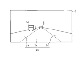
図2に示すように、画像Gにおいて、道路ZEは車両走行方向が同一の3つの車線ZA,ZB,ZCを有する。自車両は自車線ZAを走行している。車線ZBは自車線ZAの左隣の左隣車線であり、車線ZCは自車線ZAの右隣の右隣車線である。各車線ZA,ZB,ZCの左右の境界部は、例えば白線等を含む区画線(レーンマーカ)である。本実施形態では、各車線ZA,ZB,ZCの左右の境界部は白線とする。
As shown in FIG. 2, in the image G, the road ZE has three lanes ZA, ZB, and ZC having the same vehicle traveling direction. The own vehicle is traveling in the own lane ZA. Lane ZB is the lane to the left of own lane ZA, and lane ZC is the lane to the right of own lane ZA. The left and right boundary portions of the lanes ZA, ZB, and ZC are lane markers including, for example, white lines. In the present embodiment, the left and right boundaries of each lane ZA, ZB, and ZC are white lines.
自車線ZAにおいて、自車両の走行方向前方を走行する他車両51が存在する。ECU10は、他車両51をACC制御における先行車両として選出し、追従走行を行っている。
In the own lane ZA, there is another vehicle 51 traveling ahead in the traveling direction of the own vehicle. The ECU 10 selects another vehicle 51 as a preceding vehicle in ACC control and performs follow-up travel.
左隣車線ZBにおいて、自車両の走行方向前方を走行する他車両52が存在する。ここで、他車両52が、自車線ZAに進入してくることが考えられる。この場合、他車両52を先行車両とするACC制御や、他車両52に対するPCS制御が適切に実施されるには、道路ZEに対する他車両52の位置を適切に把握する必要がある。
In the left adjacent lane ZB, there is another vehicle 52 traveling ahead in the traveling direction of the own vehicle. Here, it is conceivable that another vehicle 52 enters the own lane ZA. In this case, in order to properly implement the ACC control with the other vehicle 52 as the preceding vehicle and the PCS control for the other vehicle 52, it is necessary to appropriately grasp the position of the other vehicle 52 with respect to the road ZE.
そこで、本実施形態では、左隣車線ZBを走行する他車両52の所定部位と自車線ZAとの間の位置関係を適正に把握すべく、以下に説明する画像認識が行われる構成とした。なお、本実施形態において、他車両51,52が「前方物体」に相当する。
Therefore, in the present embodiment, in order to properly grasp the positional relationship between the predetermined portion of the other vehicle 52 traveling in the left adjacent lane ZB and the own lane ZA, the image recognition described below is performed. In this embodiment, the other vehicles 51 and 52 correspond to "forward objects".
図3は、ECU10の画像認識結果を示す図である。ここでは特に、他車両51,52のうち、左隣車線ZBを走行する他車両52に対する画像認識結果を詳述する。
FIG. 3 is a diagram showing an image recognition result of the ECU 10. Here, in particular, among the other vehicles 51 and 52, the image recognition results for the other vehicle 52 traveling in the left adjacent lane ZB will be described in detail.
ECU10は、画像Gにおいて、自車線ZAの左右の区画線である左側区画線SSL及び右側区画線SSRを認識する。具体的には、ECU10は、画像G上での輝度変化に基づいて、各区画線SSL,SSRを実区画線SS1として認識する。また、画像Gにおいて、白線等の区画線が見えていない又は見えにくくなっていることがある。この場合、ECU10は、セマンティックセグメンテーションのような画像認識処理を行うことにより、画像G内で見えていない又は見えにくくなっている各区画線SSL,SSRを仮想区画線SS2として認定する。例えば、ECU10は、各区画線SSL,SSRを実区画線SS1として認識できない場合に、各区画線SSL,SSRを仮想区画線SS2として認識する。ただし、実区画線SS1の認識の可否にかかわらず、常に仮想区画線SS2を認識する構成であってもよい。また、ECU10は、自車両の前方を走行する他車両51,52の存在を認識する。
The ECU 10 recognizes the left side division line SSL and the right side division line SSR, which are the left and right division lines of the own lane ZA, in the image G. Specifically, the ECU 10 recognizes each lane marking SSL and SSR as the actual lane marking SS1 based on the change in brightness on the image G. Further, in the image G, the dividing line such as the white line may not be visible or may be difficult to see. In this case, the ECU 10 recognizes each lane marking SSL, SSR that is not visible or difficult to see in the image G as a virtual lane marking SS2 by performing an image recognition process such as semantic segmentation. For example, when the ECU 10 cannot recognize the lane markings SSL and SSR as the real lane markings SS1, the ECU 10 recognizes the lane markings SSL and SSR as the virtual lane markings SS2. However, the configuration may always recognize the virtual lane marking SS2 regardless of whether the real lane marking SS1 can be recognized. Further, the ECU 10 recognizes the existence of other vehicles 51 and 52 traveling in front of the own vehicle.
ECU10は、画像Gにおいて、他車両52の背面52aにおける右下隅の第1端部P1及び左下隅の第2端部P2と、他車両52の右側側面52bにおける前下隅の第3端部P3とを算出する。なお、これら各端部P1~P3が他車両52における「物体点」に相当する。
In the image G, the ECU 10 has a first end P1 in the lower right corner and a second end P2 in the lower left corner on the back surface 52a of the other vehicle 52, and a third end P3 in the front lower corner on the right side surface 52b of the other vehicle 52. Is calculated. Each of these ends P1 to P3 corresponds to an "object point" in the other vehicle 52.
ECU10は、画像Gにおいて、算出された端部P1~P3ごとに、各端部P1~P3を通り、かつ自車両の車幅方向(すなわち画像Gの横方向)に延びる同一線上となる位置で、左側区画線SSL上の境界点Q1~Q3を算出する。第1境界点Q1は、第1端部P1に対応する左側区画線SSL上の位置を示し、第2境界点Q2は、第2端部P2に対応する左側区画線SSL上の位置を示し、第3境界点Q3は、第3端部P3に対応する左側区画線SSL上の位置を示す。なお、図3では、他車両52が左隣車線ZBに沿って直進走行しており、左側区画線SSL上の境界点Q1,Q2が一致している。
In the image G, the ECU 10 is located on the same line extending in the vehicle width direction (that is, the lateral direction of the image G) of the own vehicle, passing through the respective end portions P1 to P3 for each of the calculated end portions P1 to P3. , Calculate the boundary points Q1 to Q3 on the left side division line SSL. The first boundary point Q1 indicates a position on the left side dividing line SSL corresponding to the first end portion P1, and the second boundary point Q2 indicates a position on the left side dividing line SSL corresponding to the second end portion P2. The third boundary point Q3 indicates a position on the left side division line SSL corresponding to the third end portion P3. In FIG. 3, the other vehicle 52 is traveling straight along the left adjacent lane ZB, and the boundary points Q1 and Q2 on the left side division line SSL coincide with each other.
ECU10は、他車両52の各端部P1~P3及び各境界点Q1~Q3に基づいて、画像Gの原点Oを基準とする角度幅θを算出する。ECU10は、角度幅θに基づいて、端部と境界点との間の横距離Wを算出する。なお、本実施形態では、画像Gの下端部中央位置を原点Oとしているが、その位置は変更可能である。
The ECU 10 calculates the angle width θ with respect to the origin O of the image G based on the end portions P1 to P3 of the other vehicle 52 and the boundary points Q1 to Q3. The ECU 10 calculates the lateral distance W between the end portion and the boundary point based on the angle width θ. In the present embodiment, the center position of the lower end portion of the image G is set as the origin O, but the position can be changed.
以下に、図4を参照しつつ、角度幅θ及び横距離Wの算出方法の一例を説明する。
Below, an example of the calculation method of the angle width θ and the lateral distance W will be described with reference to FIG.
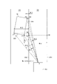
図4は、左隣車線ZBを走行する他車両52について、角度幅θ及び横距離Wの算出方法を示す図である。図4において、先の図3と同一の構成については、同一の符号を付している。なお、図4では、説明の便宜上、他車両52の進行方向が自車線寄りに傾いた状態が示されている。
FIG. 4 is a diagram showing a method of calculating the angle width θ and the lateral distance W for the other vehicle 52 traveling in the left adjacent lane ZB. In FIG. 4, the same components as those in FIG. 3 above are designated by the same reference numerals. Note that FIG. 4 shows a state in which the traveling direction of the other vehicle 52 is tilted toward the own lane for convenience of explanation.
ECU10は、他車両52の各端部P1~P3と左側区画線SSL上の各境界点Q1~Q3とに基づいて、端部P1~P3ごとに、左側角度幅θL1~θL3を算出する。詳しくは、ECU10は、原点Oを基準として、第1端部P1と第1境界点Q1とについて第1左側角度幅θL1を算出し、第2端部P2と第2境界点Q2とについて第2左側角度幅θL2を算出し、第3端部P3と第3境界点Q3とについて第3左側角度幅θL3を算出する。
The ECU 10 calculates the left side angle widths θL1 to θL3 for each of the end portions P1 to P3 based on the respective end portions P1 to P3 of the other vehicle 52 and the respective boundary points Q1 to Q3 on the left side division line SSL. Specifically, the ECU 10 calculates the first left angle width θL1 for the first end portion P1 and the first boundary point Q1 with reference to the origin O, and second for the second end portion P2 and the second boundary point Q2. The left angle width θL2 is calculated, and the third left angle width θL3 is calculated for the third end portion P3 and the third boundary point Q3.
ECU10は、他車両52の各端部P1~P3について自車両50からの距離情報を取得する。ECU10は、例えば、画像Gの縦方向において画像下端部を基準位置とし、その画像下端部から各端部P1~P3までの縦方向長さを算出するとともに、その縦方向長さに基づいて、各端部P1~P3までの距離を画像距離として算出する。
The ECU 10 acquires distance information from the own vehicle 50 for each end P1 to P3 of the other vehicle 52. For example, the ECU 10 uses the lower end of the image as a reference position in the vertical direction of the image G, calculates the vertical length from the lower end of the image to each end P1 to P3, and based on the vertical length, the ECU 10. The distance from each end P1 to P3 is calculated as the image distance.
そして、ECU10は、各左側角度幅θL1~θL3と各端部P1~P3の画像距離とに基づいて、端部P1~P3ごとに、左側横距離WL1~WL3を算出する。このとき、ECU10は、
・第1端部P1と第1境界点Q1との間の距離である第1左側横距離WL1を、第1左側角度幅θL1と第1端部P1までの画像距離とに基づいて算出し、
・第2端部P2と第2境界点Q2との間の距離である第2左側横距離WL2を、第2左側角度幅θL2と第2端部P2までの画像距離とに基づいて算出し、
・第3端部P3と第3境界点Q3との間の距離である第3左側横距離WL3を、第3左側角度幅θL3と第3端部P3までの画像距離とに基づいて算出する。
各左側横距離WL1~WL3の値は、例えば、左側区画線SSLに対して自車線ZA側を負側、左側区画線SSLに対して反自車線側を正側として算出される。 Then, theECU 10 calculates the left lateral distances WL1 to WL3 for each of the end portions P1 to P3 based on the left angle widths θL1 to θL3 and the image distances of the end portions P1 to P3. At this time, the ECU 10 is
The first left lateral distance WL1, which is the distance between the first end P1 and the first boundary point Q1, is calculated based on the first left angle width θL1 and the image distance to the first end P1.
The second left lateral distance WL2, which is the distance between the second end P2 and the second boundary point Q2, is calculated based on the second left angular width θL2 and the image distance to the second end P2.
The third left lateral distance WL3, which is the distance between the third end P3 and the third boundary point Q3, is calculated based on the third left angular width θL3 and the image distance to the third end P3.
The values of the left lateral distances WL1 to WL3 are calculated, for example, with the own lane ZA side as the negative side with respect to the left side division line SSL and the anti-own lane side as the positive side with respect to the left side division line SSL.
・第1端部P1と第1境界点Q1との間の距離である第1左側横距離WL1を、第1左側角度幅θL1と第1端部P1までの画像距離とに基づいて算出し、
・第2端部P2と第2境界点Q2との間の距離である第2左側横距離WL2を、第2左側角度幅θL2と第2端部P2までの画像距離とに基づいて算出し、
・第3端部P3と第3境界点Q3との間の距離である第3左側横距離WL3を、第3左側角度幅θL3と第3端部P3までの画像距離とに基づいて算出する。
各左側横距離WL1~WL3の値は、例えば、左側区画線SSLに対して自車線ZA側を負側、左側区画線SSLに対して反自車線側を正側として算出される。 Then, the
The first left lateral distance WL1, which is the distance between the first end P1 and the first boundary point Q1, is calculated based on the first left angle width θL1 and the image distance to the first end P1.
The second left lateral distance WL2, which is the distance between the second end P2 and the second boundary point Q2, is calculated based on the second left angular width θL2 and the image distance to the second end P2.
The third left lateral distance WL3, which is the distance between the third end P3 and the third boundary point Q3, is calculated based on the third left angular width θL3 and the image distance to the third end P3.
The values of the left lateral distances WL1 to WL3 are calculated, for example, with the own lane ZA side as the negative side with respect to the left side division line SSL and the anti-own lane side as the positive side with respect to the left side division line SSL.
ここで、画像Gに基づき算出される各端部P1~P3の画像距離は誤差を含むことが考えられる。そのため、画像距離を用いて算出された横距離WL1~WL3を、レーダセンサ22の検出情報を用いて補正することが望ましい。この場合、各端部P1~P3までの画像距離と、レーダセンサ22により計測された計測距離との差異に基づいて、横距離WL1~WL3が補正されるとよい。
Here, it is conceivable that the image distances of the ends P1 to P3 calculated based on the image G include an error. Therefore, it is desirable to correct the lateral distances WL1 to WL3 calculated using the image distance by using the detection information of the radar sensor 22. In this case, it is preferable that the lateral distances WL1 to WL3 are corrected based on the difference between the image distances from the ends P1 to P3 and the measured distances measured by the radar sensor 22.
ECU10は、左側区画線SSL上の第1~第3境界点Q1~Q3に加え、右側区画線SSRにおいて第1端部P1に対応する第4境界点Q4を算出する。第4境界点Q4は、右側区画線SSR上において、第1端部P1を通り、かつ自車両50の車幅方向に延びる同一線上となる位置である。この第4境界点Q4を用いることにより、第1端部P1と、右側区画線SSR上の第4境界点Q4との間の横距離WL4の算出が可能となっている。
The ECU 10 calculates the fourth boundary point Q4 corresponding to the first end P1 in the right side division line SSR, in addition to the first to third boundary points Q1 to Q3 on the left side division line SSL. The fourth boundary point Q4 is a position on the right side division line SSR that passes through the first end portion P1 and is on the same line extending in the vehicle width direction of the own vehicle 50. By using this fourth boundary point Q4, it is possible to calculate the lateral distance WL4 between the first end portion P1 and the fourth boundary point Q4 on the right side division line SSR.
ここまでは、左隣車線ZBを走行する他車両52についての横距離WLの算出手順を説明したが、右隣車線ZCを他車両が走行する場合には、その右隣車線ZCの他車両についても同様の処理を行うことが可能である。
Up to this point, the procedure for calculating the lateral distance WL for the other vehicle 52 traveling in the left adjacent lane ZB has been described, but when another vehicle travels in the right adjacent lane ZC, the other vehicle in the right adjacent lane ZC is used. Can also perform the same processing.
図5は、左隣車線ZBを走行する他車両52について算出される左側横距離WL1~WL3と、右隣車線ZCを走行する他車両53とについて算出される右側横距離WR1~WR3とを示す図である。
FIG. 5 shows the left lateral distances WL1 to WL3 calculated for the other vehicle 52 traveling in the left adjacent lane ZB and the right lateral distances WR1 to WR3 calculated for the other vehicle 53 traveling in the right adjacent lane ZC. It is a figure.
ECU10は、右隣車線ZCを走行する他車両53の背面53aにおいて左下隅の第1端部P11及び右下隅の第2端部P12を算出するとともに、他車両53の左側側面53bにおいて前下隅の第3端部P13を算出する。そして、ECU10は、各端部P11~P13について、右側区画線SSRまでの横距離として第1右側横距離WR1、第2右側横距離WR2、第3右側横距離WR3をそれぞれ算出する。右側横距離WR1~WR3の値は、例えば、右側区画線SSRに対して自車線ZA側を負側、右側区画線SSRに対して反自車線側を正側として算出される。
The ECU 10 calculates the first end P11 in the lower left corner and the second end P12 in the lower right corner on the back surface 53a of the other vehicle 53 traveling in the right adjacent lane ZC, and also calculates the second end P12 in the lower right corner and the front lower corner on the left side surface 53b of the other vehicle 53. The third end P13 is calculated. Then, the ECU 10 calculates the first right lateral distance WR1, the second right lateral distance WR2, and the third right lateral distance WR3 as the lateral distances to the right side division line SSR for each of the end portions P11 to P13. The values of the right lateral distances WR1 to WR3 are calculated, for example, with the own lane ZA side as the negative side with respect to the right side division line SSR and the anti-own lane side as the positive side with respect to the right side division line SSR.
不図示とするが、自車線ZAにおいて自車両前方を走行する他車両51についても同様に、横距離の算出が可能である。すなわち、ECU10は、他車両51の背面における左下隅の端部について、左側区画線SSLまでの横距離を算出するとともに、他車両51の背面における右下隅の端部について、右側区画線SSRまでの横距離を算出する。
Although not shown, it is possible to calculate the lateral distance in the same manner for the other vehicle 51 traveling in front of the own vehicle in the own lane ZA. That is, the ECU 10 calculates the lateral distance to the left side division line SSL for the end of the lower left corner on the back surface of the other vehicle 51, and the end of the lower right corner on the back surface of the other vehicle 51 to the right side division line SSL. Calculate the lateral distance.
ECU10は、ACC制御を実施する場合に、各横距離WL1~WL3,WR1~WR3に基づいて、他車両52,53を先行車両とするか否かの判定、すなわち他車両52,53が自車線ZAに割り込んだか否かの割り込み判定を実施する。このとき、左隣車線ZBを走行する他車両52については、左側横距離WL1~WL3に基づいて割り込み判定が実施され、右隣車線ZCを走行する他車両53については、右側横距離WR1~WR3に基づいて割り込み判定が実施される。
When the ECU 10 performs ACC control, it determines whether or not the other vehicles 52 and 53 are the preceding vehicles based on the respective lateral distances WL1 to WL3 and WR1 to WR3, that is, the other vehicles 52 and 53 are in their own lane. Performs an interrupt determination as to whether or not the vehicle has interrupted ZA. At this time, the interrupt determination is performed for the other vehicle 52 traveling in the left adjacent lane ZB based on the left lateral distances WL1 to WL3, and for the other vehicle 53 traveling in the right adjacent lane ZC, the interrupt determination is performed. The interrupt determination is performed based on.
ECU10は、隣車線の他車両52,53が自車線ZAに割り込む際に、各区画線SSL,SSRに対する他車両52,53における各端部の位置に応じて割り込みが生じたか否かを判定する。詳しくは、ECU10は、左隣車線ZBの他車両52について、左側横距離WL1~WL3がいずれも正の値である場合に、他車両52が左隣車線ZBを走行していると判定し、この状態から、左側横距離WL1~WL3のうち少なくとも1つが負の値に移行する場合に、他車両52が自車線ZAへと割り込んだと判定する。
When the other vehicles 52 and 53 in the adjacent lane interrupt the own lane ZA, the ECU 10 determines whether or not an interruption has occurred according to the position of each end of the other vehicles 52 and 53 with respect to the respective lanes SSL and SSR. .. Specifically, the ECU 10 determines that the other vehicle 52 is traveling in the left adjacent lane ZB when the left lateral distances WL1 to WL3 are all positive values for the other vehicle 52 in the left adjacent lane ZB. From this state, when at least one of the left lateral distances WL1 to WL3 shifts to a negative value, it is determined that the other vehicle 52 interrupts the own lane ZA.
また、ECU10は、右隣車線ZCの他車両53について、右側横距離WR1~WR3がいずれも正の値である場合に、他車両53が右隣車線ZCを走行していると判定し、この状態から、右側横距離WR1~WR3のうち少なくとも1つが負の値に移行する場合に、他車両53が自車線ZAへと割り込んだと判定する。
Further, the ECU 10 determines that the other vehicle 53 is traveling in the right adjacent lane ZC when the right lateral distances WR1 to WR3 are all positive values for the other vehicle 53 in the right adjacent lane ZC. When at least one of the right lateral distances WR1 to WR3 shifts to a negative value from the state, it is determined that the other vehicle 53 interrupts the own lane ZA.
本実施形態では、他車両52の左側横距離WL1~WL3のうち少なくとも1つが負の値に移行した場合に、その状態が所定時間継続することに基づいて、他車両52が自車線ZAへと割り込んだと判定することとしている。具体的には、左側横距離WL1~WL3のうち少なくとも1つが負の値に移行した場合に、カウント部Cによりその継続時間を計測し、カウント部Cによる計測時間(カウント値j)が所定値に達することに基づいて、他車両52をACC制御での先行車両とする旨の判定を行う。他車両53についても同様である。
In the present embodiment, when at least one of the left lateral distances WL1 to WL3 of the other vehicle 52 shifts to a negative value, the other vehicle 52 moves to the own lane ZA based on the fact that the state continues for a predetermined time. It is determined that the interruption has occurred. Specifically, when at least one of the left lateral distances WL1 to WL3 shifts to a negative value, the count unit C measures the duration, and the measurement time (count value j) by the count unit C is a predetermined value. Based on the above, it is determined that the other vehicle 52 is the preceding vehicle under ACC control. The same applies to the other vehicle 53.
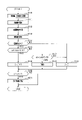
図6に、ECU10が行うACC制御の処理手順を示す。この処理は所定周期毎に実施される。
FIG. 6 shows a processing procedure of ACC control performed by the ECU 10. This process is carried out at predetermined intervals.
ステップS10では、カメラ画像に基づいて、隣車線ZB,ZCを走行する他車両52,53と各区画線SSL,SSRとを認識する。自車両50の前方において、左隣車線ZBを他車両52が走行している場合に、他車両52の存在が認識され、右隣車線ZCを他車両53が走行している場合に、他車両53の存在が認識される。各区画線SSL,SSRについては、各区画線SSL,SSRとして白線等の実区画線SS1が認識されるとともに、実区画線SS1を認識できない場合に仮想区画線SS2が認識される。実区画線SS1の認識の可否にかかわらず、仮想区画線SS2が常に認識される構成とすることも可能である。本実施形態において、ステップS10が「認識部」に相当する。
In step S10, the other vehicles 52 and 53 traveling in the adjacent lanes ZB and ZC and the respective lane markings SSL and SSR are recognized based on the camera image. In front of the own vehicle 50, when the other vehicle 52 is traveling in the left adjacent lane ZB, the existence of the other vehicle 52 is recognized, and when the other vehicle 53 is traveling in the right adjacent lane ZC, the other vehicle The existence of 53 is recognized. For each lane marking SSL, SSR, the real lane marking SS1 such as a white line is recognized as each lane marking SSL, SSR, and the virtual lane marking SS2 is recognized when the real lane marking SS1 cannot be recognized. Regardless of whether the real lane marking line SS1 can be recognized or not, the virtual lane marking line SS2 can always be recognized. In this embodiment, step S10 corresponds to the "recognition unit".
ステップS11では、各他車両52,53について各端部での角度幅θを算出する。ここで、左隣車線ZBを走行する他車両52が存在する場合には、その他車両52の所定部位である各端部P1~P3と、左側区画線SSL上の各境界点Q1~Q3とに基づいて、各端部P1~P3での角度幅θL1~θl3が算出される。このとき、左側区画線SSLが実区画線SS1として認識されていれば、その実区画線SS1上の境界点Q1~Q3を用いて角度幅θL1~θl3が算出される。また、左側区画線SSLが実区画線SS1として認識されず仮想区画線SS2として認識されていれば、その仮想区画線SS2上の境界点Q1~Q3を用いて角度幅θL1~θl3が算出される。右隣車線ZCを走行する他車両53が存在する場合には、その他車両53について同様の処理が実施される。本実施形態において、ステップS11が「角度幅算出部」に相当する。
In step S11, the angle width θ at each end of each of the other vehicles 52 and 53 is calculated. Here, when there is another vehicle 52 traveling in the left adjacent lane ZB, each end portion P1 to P3 which is a predetermined portion of the other vehicle 52 and each boundary point Q1 to Q3 on the left side division line SSL Based on this, the angle widths θL1 to θl3 at each end P1 to P3 are calculated. At this time, if the left side division line SSL is recognized as the actual division line SS1, the angle widths θL1 to θl3 are calculated using the boundary points Q1 to Q3 on the real division line SS1. If the left lane marking SSL is not recognized as the real lane marking SS1 but is recognized as the virtual lane marking SS2, the angle widths θL1 to θl3 are calculated using the boundary points Q1 to Q3 on the virtual lane marking SS2. .. If there is another vehicle 53 traveling in the right adjacent lane ZC, the same processing is performed for the other vehicle 53. In this embodiment, step S11 corresponds to the "angle width calculation unit".
ステップS12では、他車両52の各端部P1~P3及び他車両53の各端部P11~P13について距離情報を取得する。この距離情報には、画像Gから求められる画像距離やレーダセンサ22により計測された計測距離が含まれる。
In step S12, distance information is acquired for each end P1 to P3 of the other vehicle 52 and each end P11 to P13 of the other vehicle 53. This distance information includes the image distance obtained from the image G and the measured distance measured by the radar sensor 22.
ステップS13では、各他車両52,53について、角度幅θ及び距離情報に基づいて横距離Wを算出する。具体的には、左隣車線ZBの他車両52について、左側区画線SSLを基準線とする第1~第3左側横距離WL1~WL3と、右側区画線SSRを基準線とする横距離WL4とを算出する。また、右隣車線ZCの他車両53について、右側区画線SSRを基準線とする第1~第3右側横距離WR1~WR3を算出する。本実施形態において、ステップS13が「横距離算出部」に相当する。
In step S13, the lateral distance W is calculated for each of the other vehicles 52 and 53 based on the angle width θ and the distance information. Specifically, for the other vehicle 52 in the left adjacent lane ZB, the first to third left lateral distances WL1 to WL3 with the left lane marking SSL as the reference line and the lateral distance WL4 with the right lane marking SSR as the reference line. Is calculated. Further, for the other vehicle 53 of the right adjacent lane ZC, the first to third right lateral distances WR1 to WR3 with the right side division line SSR as the reference line are calculated. In this embodiment, step S13 corresponds to the "lateral distance calculation unit".
ステップS14では、各区画線SSL,SSRの認識結果について信頼性の有無を判定する。詳しくは、他車両52の第1端部P1について、左側区画線SSL上の第1境界点Q1との横距離WL1と、右側区画線SSR上の第4境界点Q4との横距離WL4との差である距離差ΔWを算出する。そして、距離差ΔWと、予め定められた自車線ZAの車線幅Wrn(実車線幅)とを対比し、それら距離差ΔWと車線幅Wrnとの差が所定以内であれば、各区画線SSL,SSRの認識結果について信頼性があると判定する。一方、距離差ΔWと車線幅Wrnとの差が所定以内になければ、各区画線SSL,SSRの認識結果について信頼性がないと判定する。この場合、距離差ΔWと車線幅Wrnとの差が所定以内であること、すなわち距離差ΔWが自車線ZAの車線幅相当の値になっていることは、各区画線SSL,SSRが適正に認識されていることを意味する。なお、車線幅Wrnは、予め定められた一定寸法の車線幅でもよいし、道路ごとに定められた車線幅でもよい。
In step S14, it is determined whether or not the recognition result of each lane marking SSL and SSR is reliable. Specifically, regarding the first end portion P1 of the other vehicle 52, the lateral distance WL1 with the first boundary point Q1 on the left side division line SSL and the lateral distance WL4 with the fourth boundary point Q4 on the right side division line SSR. The distance difference ΔW, which is the difference, is calculated. Then, the distance difference ΔW is compared with the lane width Wrn (actual lane width) of the own lane ZA determined in advance, and if the difference between the distance difference ΔW and the lane width Wrn is within a predetermined range, each lane line SSL. , Judge that the recognition result of SSR is reliable. On the other hand, if the difference between the distance difference ΔW and the lane width Wrn is not within a predetermined range, it is determined that the recognition results of the respective lane markings SSL and SSR are unreliable. In this case, the difference between the distance difference ΔW and the lane width Wrn is within a predetermined range, that is, the distance difference ΔW is a value equivalent to the lane width of the own lane ZA. It means being recognized. The lane width Wrn may be a predetermined lane width having a certain dimension, or may be a lane width determined for each road.
本実施形態では、距離差ΔWと車線幅Wrnとの差が所定以内であることを条件に、すなわち各区画線SSL,SSRの認識結果について信頼性があると判定されたことを条件に、各横距離WL1~WL3,WR1~WR3に基づく割り込み判定(先行車両判定)を行うこととしている。したがって、ステップS14において信頼性有りと判定されると、ステップS15に進み、後続の割り込み判定を実施する。一方、ステップS14において信頼性無しと判定されると、ステップS19に進む。ステップS19では、割り込み判定に用いるカウント部Cのカウント値jをリセットする。
In the present embodiment, each is on the condition that the difference between the distance difference ΔW and the lane width Wrn is within a predetermined range, that is, on the condition that the recognition results of the respective lane markings SSL and SSR are determined to be reliable. Interrupt determination (preceding vehicle determination) is performed based on the lateral distances WL1 to WL3 and WR1 to WR3. Therefore, if it is determined in step S14 that there is reliability, the process proceeds to step S15, and subsequent interrupt determination is performed. On the other hand, if it is determined in step S14 that there is no reliability, the process proceeds to step S19. In step S19, the count value j of the count unit C used for the interrupt determination is reset.
ステップS15では、各他車両52,53について、実区画線SS1上の各境界点を用いて算出された各横距離WL1~WL3,WR1~WR3に基づいて、他車両52,53が自車線ZA内に割り込もうとしているか否かを判定する。具体的には、左側区画線SSLが実区画線SS1として認識されている場合に、他車両52において、左側区画線SSLに基づき算出された各端部P1~P3の左側横距離WL1~WL3のうち負の値になるものがあるか否かを判定する。この場合、左側横距離WL1~WL3がいずれも正の値であれば、ステップS15を否定判定し、左側横距離WL1~WL3のうち少なくとも1つが負の値であれば、ステップS15を肯定判定する。
In step S15, for each of the other vehicles 52 and 53, the other vehicles 52 and 53 are in their own lane ZA based on the respective lateral distances WL1 to WL3 and WR1 to WR3 calculated using each boundary point on the actual lane marking SS1. Determine if you are trying to interrupt. Specifically, when the left lane marking SSL is recognized as the actual lane marking SS1, the left lateral distances WL1 to WL3 of the ends P1 to P3 calculated based on the left lane marking SSL in the other vehicle 52. Determine if any of them have a negative value. In this case, if the left lateral distances WL1 to WL3 are all positive values, step S15 is negatively determined, and if at least one of the left lateral distances WL1 to WL3 is a negative value, step S15 is positively determined. ..
また、右側区画線SSRが実区画線SS1として認識されている場合に、他車両53において、右側区画線SSRに基づき算出された各端部P11~P13の右側横距離WR1~WR3のうち負の値になるものがあるか否かを判定する。この場合、右側横距離WR1~WR3がいずれも正の値であれば、ステップS15を否定判定し、右側横距離WR1~WR3のうち少なくとも1つが負の値であれば、ステップS15を肯定判定する。
Further, when the right lane marking SSR is recognized as the actual lane marking SS1, the other vehicle 53 has a negative of the right lateral distances WR1 to WR3 of the ends P11 to P13 calculated based on the right lane marking SSR. Determine if there is a value. In this case, if the right lateral distances WR1 to WR3 are all positive values, step S15 is negatively determined, and if at least one of the right lateral distances WR1 to WR3 is a negative value, step S15 is positively determined. ..
ステップS15において肯定判定した場合、ステップS16に進む。また、ステップS15において否定判定した場合、ステップS17に進む。
If an affirmative judgment is made in step S15, the process proceeds to step S16. If a negative determination is made in step S15, the process proceeds to step S17.
ちなみに、例えば他車両52が左隣車線ZBから自車線ZAに進入しようとする際には、左側区画線SSLの一部が他車両52により覆い隠され、見えなくなることが考えられる。ただしこの場合、左側区画線SSLで見えなくなったのが他車両52により隠された一部分のみであれば、見えている左側区画線SSLによる補間が行われ、補間後の実区画線SS1により、実区画線SS1上の境界点Q1~Q3の算出が行われるとよい。各区画線SSL,SSRについて、例えば自車両50から他車両52,53に至るまでの範囲で実区画線SS1が認識されない場合に、ステップS15が否定判定されるとよい。
By the way, for example, when another vehicle 52 tries to enter the own lane ZA from the left adjacent lane ZB, it is conceivable that a part of the left side lane SSL is covered by the other vehicle 52 and cannot be seen. However, in this case, if only a part hidden by the other vehicle 52 is obscured by the left side lane marking SSL, the interpolation by the visible left side lane marking SSL is performed, and the actual lane marking SS1 after the interpolation actually causes the interpolation. It is preferable that the boundary points Q1 to Q3 on the lane marking SS1 are calculated. For each lane marking SSL, SSR, for example, when the actual lane marking SS1 is not recognized in the range from the own vehicle 50 to the other vehicles 52, 53, the step S15 may be negatively determined.
ステップS16では、カウント部Cのカウント値jをインクリメントする。本実施形態では、カウント値jを1プラスする。カウント部Cのカウントは、左隣車線ZBの他車両52と右隣車線ZCの他車両53でそれぞれ個別に行われる。
In step S16, the count value j of the count unit C is incremented. In this embodiment, the count value j is added by 1. The counting of the counting unit C is performed individually for the other vehicle 52 in the left adjacent lane ZB and the other vehicle 53 in the right adjacent lane ZC.
ステップS17では、各他車両52,53について、実区画線SS1上の各境界点でなく、仮想区画線SS2上の各境界点を用いて算出された各横距離WL1~WL3,WR1~WR3に基づいて、他車両52,53が自車線ZA内に割り込もうとしているか否かを判定する。具体的には、左側区画線SSLが実区画線SS1でなく仮想区画線SS2として認識されている場合に、他車両52において、左側区画線SSLに基づき算出された各端部P1~P3の左側横距離WL1~WL3のうち負の値になるものがあるか否かを判定する。この場合、左側横距離WL1~WL3がいずれも正の値であれば、ステップS17を否定判定し、左側横距離WL1~WL3のうち少なくとも1つが負の値であれば、ステップS17を肯定判定する。
In step S17, for each of the other vehicles 52 and 53, the lateral distances WL1 to WL3 and WR1 to WR3 calculated using each boundary point on the virtual lane marking line SS2 instead of each boundary point on the real lane marking line SS1. Based on this, it is determined whether or not the other vehicles 52 and 53 are trying to interrupt the own lane ZA. Specifically, when the left lane marking SSL is recognized as the virtual lane marking SS2 instead of the real lane marking SS1, the left side of each end P1 to P3 calculated based on the left lane marking SSL in the other vehicle 52. It is determined whether or not any of the lateral distances WL1 to WL3 has a negative value. In this case, if the left lateral distances WL1 to WL3 are all positive values, step S17 is negatively determined, and if at least one of the left lateral distances WL1 to WL3 is a negative value, step S17 is positively determined. ..
また、右側区画線SSRが実区画線SS1でなく仮想区画線SS2として認識されている場合に、他車両53において、右側区画線SSRに基づき算出された各端部P11~P13の右側横距離WR1~WR3のうち負の値になるものがあるか否かを判定する。この場合、右側横距離WR1~WR3がいずれも正の値であれば、ステップS17を否定判定し、右側横距離WR1~WR3のうち少なくとも1つが負の値であれば、ステップS17を肯定判定する。
Further, when the right lane marking SSR is recognized as the virtual lane marking SS2 instead of the real lane marking SS1, the right lateral distance WR1 of each end portion P11 to P13 calculated based on the right lane marking SSR in the other vehicle 53. -It is determined whether or not any of WR3 has a negative value. In this case, if the right lateral distances WR1 to WR3 are all positive values, step S17 is negatively determined, and if at least one of the right lateral distances WR1 to WR3 is a negative value, step S17 is positively determined. ..
ステップS17において肯定判定した場合、ステップS18に進む。ステップS18では、カウント部Cのカウント値jをそのまま維持する。ステップS17において否定判定した場合、ステップS19に進む。
If an affirmative judgment is made in step S17, the process proceeds to step S18. In step S18, the count value j of the count unit C is maintained as it is. If a negative determination is made in step S17, the process proceeds to step S19.
ここで、ステップS15,S17は、他車両52,53における各端部の横距離WL1~WL3,WR1~WR3が所定範囲内であるか否かを判定する端部判定条件(所定条件)である。ステップS15~S18によれば、実区画線SS1が認識され、かつ実区画線SS1に基づき横距離WL1~WL3,WR1~WR3が算出されている場合と、実区画線SS1でなく仮想区画線SS2が認識され、かつ仮想区画線SS2に基づき横距離WL1~WL3,WR1~WR3が算出されている場合とで、端部判定条件を用いた割り込み判定の実施態様が相違するものとなっている。
Here, steps S15 and S17 are end determination conditions (predetermined conditions) for determining whether or not the lateral distances WL1 to WL3 and WR1 to WR3 of the end portions of the other vehicles 52 and 53 are within a predetermined range. .. According to steps S15 to S18, there are cases where the real lane marking SS1 is recognized and the lateral distances WL1 to WL3 and WR1 to WR3 are calculated based on the real lane marking SS1 and the virtual lane marking SS2 instead of the real lane marking SS1. Is recognized and the lateral distances WL1 to WL3 and WR1 to WR3 are calculated based on the virtual lane marking SS2, and the embodiment of the interrupt determination using the end determination condition is different.
ステップS20では、カウント部Cのカウント値jが所定値jthよりも大きいか否かを判定する。ステップS20において肯定判定した場合、ステップS21に進む。ステップS21では、他車両52,53のうちカウント値jが所定値jthよりも大きくなった他車両を、ACC制御での先行車両であると判定する。一方、ステップS20において否定判定した場合、本処理を終了する。
In step S20, it is determined whether or not the count value j of the count unit C is larger than the predetermined value jth. If an affirmative determination is made in step S20, the process proceeds to step S21. In step S21, among the other vehicles 52 and 53, the other vehicle whose count value j is larger than the predetermined value jth is determined to be the preceding vehicle under ACC control. On the other hand, if a negative determination is made in step S20, this process ends.
カウント部Cにおいて、ステップS16では、カウント部Cのカウント値jに所定数(例えば2)を加算し、ステップS18では、カウント部Cのカウント値jに所定数よりも少ない数(例えば1)を加算する構成とすることも可能である。
In the counting unit C, in step S16, a predetermined number (for example, 2) is added to the count value j of the counting unit C, and in step S18, a number smaller than the predetermined number (for example, 1) is added to the count value j of the counting unit C. It is also possible to configure it to add.
続いて、図7を参照しつつ、ACC制御の一例について説明する。図7において、先の図7と同一の構成については、同一の符号を付している。ここでは、他車両52が左隣車線ZBから自車線ZAに進入する場合を説明する。
Subsequently, an example of ACC control will be described with reference to FIG. 7. In FIG. 7, the same components as those in FIG. 7 above are designated by the same reference numerals. Here, a case where the other vehicle 52 enters the own lane ZA from the left adjacent lane ZB will be described.
図7に示すように、他車両52が左隣車線ZBから自車線ZAに進入する際には、自車両50の進行方向に対して傾いた向きで他車両52が自車線ZAに進入してくることが考えられる。この場合、他車両52の背面における第1端部P1に対応する第1左側横距離WL1が正の値から負の値に移行する前に、他車両52の側方前端部における第3端部P3が正の値から負の値に移行する。すなわち、第1端部P1が自車線ZAに進入する前に、第3端部P3が自車線ZAに進入する。そして、第3端部P3が負の値となった状態、すなわち第3端部P3が自車線ZAに進入した状態が所定時間継続した時点で、他車両52がACC制御での先行車両であると判定される。なお、道路ZEにおいて隣車線が自車線ZAに合流する形態になっていることも考えられる。例えば道路車線数が減る場合や、高速道路等での合流車線(ランプウエイ)がこれに相当する。この場合、他車両が合流車線である隣車線から割り込む際に、上記の割り込み判定が実施されるとよい。
As shown in FIG. 7, when the other vehicle 52 enters the own lane ZA from the left adjacent lane ZB, the other vehicle 52 enters the own lane ZA in a direction inclined with respect to the traveling direction of the own vehicle 50. It is possible that it will come. In this case, the third end portion at the lateral front end portion of the other vehicle 52 before the first left lateral distance WL1 corresponding to the first end portion P1 on the back surface of the other vehicle 52 shifts from a positive value to a negative value. P3 shifts from a positive value to a negative value. That is, the third end P3 enters the own lane ZA before the first end P1 enters the own lane ZA. Then, when the third end P3 has a negative value, that is, the state in which the third end P3 has entered the own lane ZA continues for a predetermined time, the other vehicle 52 is the preceding vehicle under ACC control. Is determined. It is also conceivable that the adjacent lane merges with the own lane ZA on the road ZE. For example, when the number of road lanes is reduced, or when a merging lane (ramp way) on a highway or the like corresponds to this. In this case, it is preferable that the above interrupt determination is performed when another vehicle interrupts from the adjacent lane which is the merging lane.
また、ECU10は、自車両50の直前に他車両52が割り込んでくる場合に、その他車両52に対して、各端部P1~P3の左側横距離WL1~WL3に基づいてPCS制御を実施する。具体的には、ECU10は、図8に示すPCS制御を実施する。
Further, when the other vehicle 52 interrupts immediately before the own vehicle 50, the ECU 10 executes PCS control for the other vehicle 52 based on the left lateral distances WL1 to WL3 of the end portions P1 to P3. Specifically, the ECU 10 implements the PCS control shown in FIG.
図8において、ステップS30~S33では、図6のステップS10~S13と同様の処理を実施する。略述すると、ステップS30では、隣車線ZB,ZCを走行する他車両52,53及び各区画線SSL,SSRを認識し、ステップS31では、各他車両52,53について各端部での角度幅θを算出する。ステップS32では、他車両52,53の各端部について距離情報を取得する。ステップS33では、各他車両52,53の各端部について、角度幅θ及び距離情報に基づいて横距離Wを算出する。
In FIG. 8, in steps S30 to S33, the same processing as in steps S10 to S13 of FIG. 6 is performed. Briefly, in step S30, other vehicles 52, 53 traveling in the adjacent lanes ZB, ZC and each lane marking SSL, SSR are recognized, and in step S31, the angle width at each end of each other vehicle 52, 53. Calculate θ. In step S32, distance information is acquired for each end of each of the other vehicles 52 and 53. In step S33, the lateral distance W is calculated for each end of each of the other vehicles 52 and 53 based on the angle width θ and the distance information.
その後、ステップS34では、他車両52,53の各端部の横距離Wに基づいて、他車両52,53が自車線ZA内に割り込もうとしているか否かを判定する。例えば他車両52が自車線ZA内に割り込む際には、他車両52の第3端部P3(右前端部)が、他の端部よりも先に自車線ZA内に進入する。そのため、第3端部P3の左側横距離WL3が正の値から負の値に移行した場合に、他車両52が自車線ZA内に割り込もうとしているとみなしてステップS34を肯定判定する。なお、ステップS34で用いられる横距離Wは、実区画線SS1に基づいて算出されたもの、仮想区画線SS2に基づいて算出されたもののいずれであってもよい。
After that, in step S34, it is determined whether or not the other vehicles 52, 53 are trying to interrupt the own lane ZA based on the lateral distance W at each end of the other vehicles 52, 53. For example, when the other vehicle 52 cuts into the own lane ZA, the third end P3 (right front end) of the other vehicle 52 enters the own lane ZA before the other end. Therefore, when the left lateral distance WL3 of the third end portion P3 shifts from a positive value to a negative value, it is considered that the other vehicle 52 is about to interrupt the own lane ZA, and step S34 is positively determined. The lateral distance W used in step S34 may be either one calculated based on the real lane marking SS1 or one calculated based on the virtual lane marking SS2.
ステップS35では、自車線ZA内に進入したと判定された他車両52,53の端部について、自車両50からの直線距離を、自車両50に対する他車両52,53の相対速度で割ることによりTTCを算出する。ステップS36では、各他車両52,53のTTCと所定の閾値とを比較し、ブレーキ装置32や警報装置33を作動させるか否かを判定する。そして、ステップS36が肯定判定される場合に、ステップS37進み、制御対象となるいずれかの他車両に対する衝突回避を図るべくブレーキ装置32や警報装置33を作動させる。
In step S35, for the ends of the other vehicles 52 and 53 determined to have entered the own lane ZA, the straight line distance from the own vehicle 50 is divided by the relative speed of the other vehicles 52 and 53 with respect to the own vehicle 50. Calculate TTC. In step S36, the TTC of each of the other vehicles 52 and 53 is compared with a predetermined threshold value, and it is determined whether or not to operate the brake device 32 or the alarm device 33. Then, when the affirmative determination is made in step S36, the process proceeds to step S37, and the brake device 32 and the alarm device 33 are activated in order to avoid a collision with any other vehicle to be controlled.
要するに、図8では、他車両52,53の各端部のうち自車線ZA内に進入した端部を把握し、その端部について算出されたTTCに基づいて、ブレーキ装置32や警報装置33の作動状態を制御する。
In short, in FIG. 8, among the ends of the other vehicles 52 and 53, the end that has entered the own lane ZA is grasped, and the brake device 32 and the alarm device 33 are based on the TTC calculated for the end. Control the operating state.
なお、図8において、図6と同様に、各区画線SSL,SSRの認識結果について信頼性の有無を判定する処理(ステップS14)を実施することも可能である。
It should be noted that, in FIG. 8, similarly to FIG. 6, it is also possible to carry out a process (step S14) of determining whether or not the recognition result of each lane marking SSL and SSR is reliable.
以上詳述した本実施形態によれば、以下の効果が得られるようになる。
According to the present embodiment described in detail above, the following effects can be obtained.
画像Gにおいて、自車両50の車幅方向に延びる同一線上の他車両52,53の各端部と区画線SSL,SSR上の各境界点とについて角度幅θを算出するとともに、その角度幅θと他車両52,53の各端部までの距離情報とに基づいて、他車両52,53の各端部の横距離Wを算出する。そして、その横距離に基づいて、他車両52,53に対する走行支援制御を実施するようにした。
In the image G, the angle width θ is calculated for each end of the other vehicles 52 and 53 on the same line extending in the vehicle width direction of the own vehicle 50 and each boundary point on the lane markings SL and SSR, and the angle width θ is calculated. And the distance information to each end of the other vehicles 52 and 53, the lateral distance W of each end of the other vehicles 52 and 53 is calculated. Then, based on the lateral distance, the traveling support control for the other vehicles 52 and 53 is performed.
上記構成によれば、他車両52,53について、所望の位置で各区画線SSL,SSRに対する位置を適正に把握することができる。この場合、他車両52,53での検出すべき所定部位が走行シーン等に応じて都度変化するとしても、所望とする部位を対象にして適正な位置検出を実施することができる。これにより、他車両52,53の位置検出を適正に実施し、ひいては走行支援制御を適切に実施することができる。
According to the above configuration, it is possible to properly grasp the positions of the other vehicles 52 and 53 with respect to the respective lane markings SSL and SSR at desired positions. In this case, even if the predetermined portion to be detected in the other vehicles 52 and 53 changes each time according to the traveling scene and the like, appropriate position detection can be performed for the desired portion. As a result, the positions of the other vehicles 52 and 53 can be properly detected, and the traveling support control can be appropriately performed.
自車両前方に他車両が存在する場合には、その他車両の背面を認識した上で、ACC制御やPCS制御が実施されるが、隣車線を走行する他車両が自車線ZAに割り込む際には、他車両の向きが傾いた状態となり、他車両の背面よりも先に、車両前端部が自車線ZAに進入してくることとなる。この点、隣車線を走行する他車両52,53の背面における自車両側の横方向端部の位置と、他車両52,53の自車両側の側面における前端部の位置とで横距離Wを算出し、その横距離Wに基づいて、他車両52,53に対する走行支援制御を実施するようにした。特にACC制御では、他車両52,53の自車両側の側面における前端部の位置(横距離W)に基づいて、他車両52,53を先行車両とするか否かを判定するようにした。これにより、他車両52,53の背面の認識結果に基づいて走行支援制御を実施する場合に比べて、走行支援制御における他車両52,53への対応を早期に行わせることができ、ひいては走行支援制御の適正化を実現することができる。
If there is another vehicle in front of the own vehicle, ACC control and PCS control are performed after recognizing the back of the other vehicle, but when another vehicle traveling in the adjacent lane interrupts the own lane ZA, , The direction of the other vehicle is tilted, and the front end of the vehicle enters the own lane ZA before the back surface of the other vehicle. In this respect, the lateral distance W is determined by the position of the lateral end portion on the own vehicle side on the back surface of the other vehicles 52 and 53 traveling in the adjacent lane and the position of the front end portion on the side surface on the own vehicle side of the other vehicles 52 and 53. It was calculated, and based on the lateral distance W, running support control for other vehicles 52 and 53 was performed. In particular, in the ACC control, it is determined whether or not the other vehicles 52 and 53 are the preceding vehicles based on the position of the front end portion (lateral distance W) on the side surface of the other vehicles 52 and 53 on the own vehicle side. As a result, compared to the case where the driving support control is performed based on the recognition result of the back surface of the other vehicles 52 and 53, it is possible to make the driving support control respond to the other vehicles 52 and 53 earlier, and eventually the vehicle travels. It is possible to realize the optimization of support control.
他車両52の第1端部P1について左右の区画線SSL,SSR上の各境界点Q1,Q4の横距離WL1,WL4の距離差ΔWと、予め定められた自車線ZAの車線幅Wrn(実車線幅)との差が所定以内であることを条件に、各横距離に基づく先行車両判定を行うようにした。これにより、他車両52,53を先行車として判定する際の精度を高めることができる。
For the first end P1 of the other vehicle 52, the distance difference ΔW of the lateral distances WL1 and WL4 of the boundary points Q1 and Q4 on the left and right dividing lines SSL and SSR, and the lane width Wrn (actual vehicle) of the own lane ZA determined in advance. The preceding vehicle is determined based on each lateral distance on condition that the difference from the line width) is within a predetermined range. As a result, it is possible to improve the accuracy when determining the other vehicles 52 and 53 as the preceding vehicle.
実区画線SS1が認識され、かつ実区画線SS1に基づき横距離が算出されている場合と、実区画線SS1でなく仮想区画線SS2が認識され、かつ仮想区画線SS2に基づき横距離が算出されている場合とで、先行車両判定の実施態様を相違させるようにした。具体的には、実区画線SS1が認識され、かつ実区画線SS1に基づき横距離が算出されている場合に、他車両52,53の少なくとも一部が自車線ZA内に進入した継続時間を計測するカウント部Cのカウント値jをインクリメントする。一方、実区画線SS1でなく仮想区画線SS2が認識され、かつ仮想区画線SS2に基づき算出された横距離が所定範囲内である場合に、カウント部Cのカウント値jをそのまま維持する、又はカウント値jを所定数よりも少ない数でインクリメントするようにした。
When the real lane marking SS1 is recognized and the lateral distance is calculated based on the real lane marking SS1, the virtual lane marking SS2 is recognized instead of the real lane marking SS1 and the lateral distance is calculated based on the virtual lane marking SS2. The embodiment of the preceding vehicle determination is different from that of the case where the preceding vehicle is determined. Specifically, when the actual lane marking SS1 is recognized and the lateral distance is calculated based on the actual lane marking SS1, the duration during which at least a part of the other vehicles 52 and 53 has entered the own lane ZA is calculated. The count value j of the counting unit C to be measured is incremented. On the other hand, when the virtual lane marking SS2 is recognized instead of the real lane marking SS1 and the lateral distance calculated based on the virtual lane marking SS2 is within a predetermined range, the count value j of the counting unit C is maintained as it is, or The count value j is incremented by a number smaller than a predetermined number.
これにより、認識の信頼度が高い実区画線SS1に基づいて他車両52,53の割り込みがあったと連続して判定された場合に、他車両52,53をACC制御での先行車両とする旨が判定される。そのため、誤って他車両52,53を先行車両とする旨が判定される誤判定が生じることを抑制できる。
As a result, when it is continuously determined that the other vehicles 52 and 53 have been interrupted based on the actual lane marking SS1 with high recognition reliability, the other vehicles 52 and 53 are set as the preceding vehicle under ACC control. Is determined. Therefore, it is possible to prevent an erroneous determination that it is determined that the other vehicles 52 and 53 are the preceding vehicles by mistake.
<第2実施形態>
以下、第2実施形態について、第1実施形態との相違点を中心に説明する。本実施形態では、図9に示すように、自車両50の前方に、自車両50とは逆向きに走行する対向車両54が存在しているシーンを想定し、その対向車両54に対して実施されるPCS制御について説明する。図9では、対向車両54が、例えば急カーブを曲がった後に自車線ZA側にはみ出し、その後右隣車線ZCに戻るシーンを想定しており、その際には、対向車両54が自車両50の進行方向に対して右隣車線ZC側に傾いた向きで走行することが考えられる。 <Second Embodiment>
Hereinafter, the second embodiment will be described focusing on the differences from the first embodiment. In the present embodiment, as shown in FIG. 9, it is assumed that an oncomingvehicle 54 traveling in the opposite direction to the own vehicle 50 exists in front of the own vehicle 50, and the implementation is performed on the oncoming vehicle 54. The PCS control to be performed will be described. In FIG. 9, it is assumed that the oncoming vehicle 54 protrudes to the own lane ZA side after turning a sharp curve, and then returns to the right adjacent lane ZC. In that case, the oncoming vehicle 54 is the own vehicle 50. It is conceivable to drive in a direction inclined toward the ZC side of the right adjacent lane with respect to the traveling direction.
以下、第2実施形態について、第1実施形態との相違点を中心に説明する。本実施形態では、図9に示すように、自車両50の前方に、自車両50とは逆向きに走行する対向車両54が存在しているシーンを想定し、その対向車両54に対して実施されるPCS制御について説明する。図9では、対向車両54が、例えば急カーブを曲がった後に自車線ZA側にはみ出し、その後右隣車線ZCに戻るシーンを想定しており、その際には、対向車両54が自車両50の進行方向に対して右隣車線ZC側に傾いた向きで走行することが考えられる。 <Second Embodiment>
Hereinafter, the second embodiment will be described focusing on the differences from the first embodiment. In the present embodiment, as shown in FIG. 9, it is assumed that an oncoming
この対向車両54に対して実施されるPCS制御を、先に示した図8のフローチャートを再び用いて説明する。
The PCS control performed on the oncoming vehicle 54 will be described again using the flowchart of FIG. 8 shown above.
本実施形態では、図8のステップS30~S33において、対向車両54における物体点とである各端部P21.P22(図9参照)について横距離Wを算出する。詳しくは、ECU10は、対向車両54について前面54aの右前端部P21と、自車両側側面の右後端部P22とを算出し、それら各端部P21,P22について、既述の手法により、右側区画線SSRを基準線とする横距離WR11,WR12を算出する。なお、対向車両54の前面54aにおいて左前端部の横距離の算出は任意である。
In the present embodiment, in steps S30 to S33 of FIG. 8, each end P21 which is an object point in the oncoming vehicle 54. The lateral distance W is calculated for P22 (see FIG. 9). Specifically, the ECU 10 calculates the right front end portion P21 of the front surface 54a and the right rear end portion P22 of the side surface of the own vehicle for the oncoming vehicle 54, and for each of these end portions P21 and P22, the right side is obtained by the method described above. The lateral distances WR11 and WR12 with the lane marking SSR as the reference line are calculated. It should be noted that the calculation of the lateral distance of the left front end portion on the front surface 54a of the oncoming vehicle 54 is arbitrary.
その後、ステップS34では、対向車両54の各端部P21,P22の横距離WR21,WR22に基づいて、対向車両54が自車線ZA内に入っているか否かを判定する。対向車両54が自車線ZA内に入っている状態から右隣車線ZCへ移動する際には、対向車両54の車両前部よりも後に車両後部が右隣車線ZCに移動する。この場合、対向車両54が自車線ZA内に入っている状態では、対向車両54の右前端部P21の横距離WR21と右後端部P22の横距離WR22とが共に負の値となるか、又は、横距離WR21,WR22のうち右後端部P22の横距離WR22のみが負の値となる。これに対して、対向車両54が右隣車線ZCに移動すると、対向車両54の右前端部P21の横距離WR21と右後端部P22の横距離WR22とが共に正の値となる。
After that, in step S34, it is determined whether or not the oncoming vehicle 54 is in the own lane ZA based on the lateral distances WR21 and WR22 of the respective ends P21 and P22 of the oncoming vehicle 54. When the oncoming vehicle 54 moves from the state of being in the own lane ZA to the right adjacent lane ZC, the rear portion of the vehicle moves to the right adjacent lane ZC after the front portion of the oncoming vehicle 54. In this case, when the oncoming vehicle 54 is in the own lane ZA, whether the lateral distance WR21 of the right front end portion P21 of the oncoming vehicle 54 and the lateral distance WR22 of the right rear end portion P22 both have negative values. Alternatively, of the lateral distances WR21 and WR22, only the lateral distance WR22 at the right rear end portion P22 has a negative value. On the other hand, when the oncoming vehicle 54 moves to the right adjacent lane ZC, both the lateral distance WR21 of the right front end portion P21 of the oncoming vehicle 54 and the lateral distance WR22 of the right rear end portion P22 become positive values.
そのため、横距離WR21,WR22のうち少なくともいずれか一方が負の値であれば、ステップS34を肯定判定し、ステップS35に進む。また、横距離WR21,WR22の両方が正の値であれば、ステップS34を否定判定して本処理を終了する。
Therefore, if at least one of the lateral distances WR21 and WR22 has a negative value, the affirmative determination is made in step S34, and the process proceeds to step S35. If both the lateral distances WR21 and WR22 are positive values, step S34 is negatively determined and the present process is terminated.
ステップS35~S37では、自車線ZA内に留まっている対向車両54の各端部についてTTCを算出し、そのTTCに基づいて、ブレーキ装置32や警報装置33を適宜作動させる。
In steps S35 to S37, TTC is calculated for each end of the oncoming vehicle 54 remaining in the own lane ZA, and the brake device 32 and the alarm device 33 are appropriately operated based on the TTC.
以上詳述した本実施形態によれば、以下の効果が得られるようになる。
According to the present embodiment described in detail above, the following effects can be obtained.
対向車両54が自車線ZAから離脱する場合、対向車両54の自車線ZA側の前端部が自車両50の前方から離れたとしても、他車両53の自車線ZA側の後端部が自車両50の前方に存在している場合がある。この点、対向車両54の前面における自車両側の横方向端部の位置と、対向車両54の自車両側の側面における後端部の位置とで横距離Wを算出し、その横距離Wに基づいて、対向車両54に対するPCS制御を実施するようにした。これにより、対向車両54の前面の認識結果に基づいてPCS制御を実施する場合に比べて、対向車両54との衝突可能性を低減させることができる。
When the oncoming vehicle 54 leaves the own lane ZA, even if the front end of the oncoming vehicle 54 on the own lane ZA side is separated from the front of the own vehicle 50, the rear end of the other vehicle 53 on the own lane ZA side is the own vehicle. It may be in front of 50. In this respect, the lateral distance W is calculated from the position of the lateral end portion on the own vehicle side on the front surface of the oncoming vehicle 54 and the position of the rear end portion on the side surface of the oncoming vehicle 54 on the own vehicle side, and the lateral distance W is set to the lateral distance W. Based on this, PCS control for the oncoming vehicle 54 is performed. As a result, the possibility of collision with the oncoming vehicle 54 can be reduced as compared with the case where the PCS control is performed based on the recognition result of the front surface of the oncoming vehicle 54.
<第3実施形態>
以下、第3実施形態について、第1実施形態との相違点を中心に説明する。本実施形態において、ECU10は、自車両の走行方向前方に位置する前方物体から、自車両が走行する道路の左右の境界部までの横距離に基づいてPCS制御を実施する。本実施形態では、前方物体として例えば人や自転車を想定している。 <Third Embodiment>
Hereinafter, the third embodiment will be described focusing on the differences from the first embodiment. In the present embodiment, theECU 10 performs PCS control based on the lateral distance from the front object located in front of the traveling direction of the own vehicle to the left and right boundary portions of the road on which the own vehicle travels. In this embodiment, for example, a person or a bicycle is assumed as a forward object.
以下、第3実施形態について、第1実施形態との相違点を中心に説明する。本実施形態において、ECU10は、自車両の走行方向前方に位置する前方物体から、自車両が走行する道路の左右の境界部までの横距離に基づいてPCS制御を実施する。本実施形態では、前方物体として例えば人や自転車を想定している。 <Third Embodiment>
Hereinafter, the third embodiment will be described focusing on the differences from the first embodiment. In the present embodiment, the
本実施形態では、図10に示すように、車道である道路ZEに、左右の区画線SSL,SSRにより区画された車線が設けられるとともに、左側区画線SSLの左側方に、道路ZEの左側境界部として境界区画物BDが設けられていることを想定している。境界区画物BDは、道路ZEの左側区画線SSLに平行で、かつ左側区画線SSLよりも外側に設けられており、例えば縁石やガードレール、側溝等である。境界区画物BDの左側は、例えば歩道ZFである。なお、道路ZEにおいて左側区画線SSLと境界区画物BDとの間は路肩部分である。
In the present embodiment, as shown in FIG. 10, the road ZE, which is a roadway, is provided with lanes partitioned by the left and right lane markings SSL and SSR, and the left boundary of the road ZE is provided on the left side of the left lane marking SSL. It is assumed that the boundary partition BD is provided as a portion. The boundary section BD is provided parallel to the left side section line SSL of the road ZE and outside the left side section line SSL, and is, for example, a curb, a guardrail, a gutter, or the like. The left side of the boundary block BD is, for example, the sidewalk ZF. In addition, in the road ZE, the road shoulder portion is between the left side division line SSL and the boundary division BD.
道路ZEにおいては、白線等の区画線SSL,SSRが劣化等により見えにくくなっている、又は区画線SSL,SSRが存在していない場合がある。この場合、仮に区画線SSL,SSRを認識できない状況であると、道路境界部付近に存在する前方物体に対して、PCS制御を適正に実施できなくなることが懸念される。図10では、道路ZEの左側側方に人又は自転車である物体Xが存在しているが、左側区画線SSLを認識できない状況であると、物体Xに対してPCS制御を適正に実施できなくなることが懸念される。
On the road ZE, the lane markings SSL and SSR such as white lines may be difficult to see due to deterioration or the like, or the lane markings SSL and SSR may not exist. In this case, if the lane marking SSL and SSR cannot be recognized, there is a concern that the PCS control cannot be properly performed on the forward object existing near the road boundary. In FIG. 10, an object X, which is a person or a bicycle, exists on the left side of the road ZE, but if the left lane marking SL cannot be recognized, PCS control cannot be properly performed on the object X. Is a concern.
そこで本実施形態では、道路ZEの左右の境界部として、左右の区画線SSL,SSRと、道路ZEに沿って延び、かつ区画線SSL,SSRとは異なる道路境界である境界区画物BDとをそれぞれ認識する。そして、境界部として区画線SSL,SSRが認識された場合と、境界部として境界区画物BDが認識された場合とで、前方物体(物体X)と道路境界部との間の横距離Wに基づき実施される衝突被害軽減制御の実施態様を変更することとしている。
Therefore, in the present embodiment, as the left and right boundary portions of the road ZE, the left and right division lines SSL and SSR and the boundary division BD extending along the road ZE and having a road boundary different from the division lines SSL and SSR are provided. Recognize each. Then, in the case where the boundary line SSL and SSR are recognized as the boundary portion and the case where the boundary partition BD is recognized as the boundary portion, the lateral distance W between the front object (object X) and the road boundary portion is set. The embodiment of the collision damage mitigation control to be implemented based on the above will be changed.
物体Xの横距離Wは、図4で説明した手法により算出可能であり、ここでは簡単に説明する。図11は、歩道ZFに物体Xが存在している状況を示す画像Gである。図11には、ECU10により認識された物体Xと左右の区画線SSL,SSRと境界区画物BDとが示されている。なお、区画線SSL,SSRは、実区画線及び仮想区画線のうちいずれで認識されたものであってもよい。境界区画物BDは、ガードレール等の立体物である場合が想定されるが、図11には、路面上に境界区画物BDを投影した位置が路面投影線として示されている。
The lateral distance W of the object X can be calculated by the method described in FIG. 4, and will be briefly described here. FIG. 11 is an image G showing a situation in which the object X exists on the sidewalk ZF. FIG. 11 shows the object X recognized by the ECU 10, the left and right division lines SSL, SSR, and the boundary division BD. The lane marking SSL and SSR may be recognized as either a real lane marking or a virtual lane marking. The boundary compartment BD is assumed to be a three-dimensional object such as a guardrail, but FIG. 11 shows the position where the boundary compartment BD is projected on the road surface as a road surface projection line.
ECU10は、画像Gにおいて、自車両の車幅方向に延びる同一線上で、物体Xの所定部位(例えば右側下端部位)を示す物体点P31と、左側区画線SSL上の境界点QAと、境界区画物BDの路面投影線上の境界点QBとを算出するとともに、それら物体点P31と各境界点QA,QBとについて、原点Oを基準とする角度幅θを算出する。また、ECU10は、その角度幅θと物体点P31までの距離情報とに基づいて、物体Xと区画線SSL,SSRとの間の横距離Wを算出するとともに、物体Xと境界区画物BDとの間の横距離Wを算出する。
In the image G, the ECU 10 has an object point P31 indicating a predetermined portion of the object X (for example, a right lower end portion) on the same line extending in the vehicle width direction of the own vehicle, a boundary point QA on the left division line SSL, and a boundary division. The boundary point QB on the road surface projection line of the object BD is calculated, and the angle width θ with respect to the origin O is calculated for the object point P31 and the respective boundary points QA and QB. Further, the ECU 10 calculates the lateral distance W between the object X and the division lines SL and SSR based on the angle width θ and the distance information to the object point P31, and also determines the object X and the boundary partition BD. The lateral distance W between them is calculated.
なお、画像Gにおいて、区画線SSL,SSRが認識されている場合には、横距離Wとして、区画線SSL,SSRに基づいて横距離WAが算出され、区画線SSL,SSRが認識されず代わりに境界区画物BDが認識されている場合には、横距離Wとして、境界区画物BDに基づいて横距離WBが算出される。ただし、区画線SSL,SSRが認識されるか認識されないかにかかわらず、常に境界区画物BDに基づいて横距離WBが算出される構成であってもよい。
When the lane markings SSL and SSR are recognized in the image G, the lateral distance WA is calculated as the lateral distance W based on the lane markings SSL and SSR, and the lane markings SSL and SSR are not recognized and are replaced. When the boundary partition BD is recognized, the lateral distance WB is calculated based on the boundary partition BD as the lateral distance W. However, regardless of whether the section lines SSL and SSR are recognized or not, the lateral distance WB may always be calculated based on the boundary section BD.
ECU10は、PCS制御において、自車両50から物体Xまでの距離に基づいてTTCを算出する場合に、物体Xの横方向の位置が、区画線SSL,SSRに対する位置として把握されているか、又は境界区画物BDに対する位置として把握されているかに応じて、PCS制御の実施態様を変更する。
When the ECU 10 calculates the TTC based on the distance from the own vehicle 50 to the object X in the PCS control, the lateral position of the object X is grasped as the position with respect to the lane markings SL and SSR, or the boundary. The embodiment of the PCS control is changed depending on whether it is grasped as a position with respect to the section BD.
具体的には、ECU10は、自車両50から物体Xまでの直線距離を、自車両50に対する物体Xの相対速度で割ることによりTTCを算出する。また、ECU10は、物体Xの位置が、区画線SSL,SSRに対する位置として把握されている場合に、横距離WAに基づいてTTCを増加側に補正し、物体Xの位置が、境界区画物BDに対する位置として把握されている場合に、横距離WBに基づいてTTCを増加側に補正する。
Specifically, the ECU 10 calculates the TTC by dividing the linear distance from the own vehicle 50 to the object X by the relative speed of the object X with respect to the own vehicle 50. Further, when the position of the object X is grasped as the position with respect to the division line SSL and SSR, the ECU 10 corrects the TTC to the increasing side based on the lateral distance WA, and the position of the object X is the boundary partition BD. When it is grasped as the position with respect to, the TTC is corrected to the increasing side based on the lateral distance WB.
TTCの補正について補足する。ECU10は、例えば図12の関係を用いて、横距離WA,WBに基づいてTTC補正量を算出する。横距離WAは、区画線SSL,SSRから反自車両側への向きを正とする横距離であり、横距離WBは、境界区画物BDから反自車両側への向きを正とする横距離である。図12によれば、横距離WAに基づいて算出されるTTC補正量と、横距離WBに基づいて算出されるTTC補正量との対比において、後者の方が大きい補正量が算出されるようになっている。
Supplementary information on TTC correction. The ECU 10 calculates the TTC correction amount based on the lateral distances WA and WB, for example, using the relationship shown in FIG. The lateral distance WA is a lateral distance in which the direction from the lane markings SSL and SSR to the anti-own vehicle side is positive, and the lateral distance WB is a lateral distance in which the direction from the boundary section BD to the anti-own vehicle side is positive. Is. According to FIG. 12, in the comparison between the TTC correction amount calculated based on the lateral distance WA and the TTC correction amount calculated based on the lateral distance WB, the latter is calculated so that the larger correction amount is calculated. It has become.
図13に、ECU10が行うPCS制御の処理手順を示す。この処理は所定周期毎に実施される。
FIG. 13 shows a processing procedure of PCS control performed by the ECU 10. This process is carried out at predetermined intervals.
ステップS40では、カメラ画像に基づいて、物体Xと区画線SSL,SSRと境界区画物BDとを認識する。
In step S40, the object X, the division line SSL, the SSR, and the boundary division BD are recognized based on the camera image.
ステップS41では、物体Xの物体点P31について角度幅θを算出する。ここで、道路の境界部として、区画線SSL,SSRが認識されている場合には、物体Xの物体点P31と、区画線SSL,SSR上の境界点QAとに基づいて、角度幅θが算出される。また、道路の境界部として、区画線SSL,SSRが認識されておらず境界区画物BDが認識されている場合には、物体Xの物体点P31と、境界区画物BD(路面投影線)上の境界点QBとに基づいて、角度幅θが算出される。
In step S41, the angle width θ is calculated for the object point P31 of the object X. Here, when the lane markings SSL and SSR are recognized as the boundary portion of the road, the angle width θ is based on the object point P31 of the object X and the boundary point QA on the lane markings SSL and SSR. Calculated. Further, when the boundary line SSL and SSR are not recognized and the boundary section BD is recognized as the boundary portion of the road, the object point P31 of the object X and the boundary section BD (road surface projection line) are on. The angle width θ is calculated based on the boundary point QB of.
ステップS42では、物体Xの物体点P31について距離情報を取得する。この距離情報には、画像Gから求められる画像距離やレーダセンサ22により計測された計測距離が含まれる。
In step S42, distance information is acquired for the object point P31 of the object X. This distance information includes the image distance obtained from the image G and the measured distance measured by the radar sensor 22.
ステップS43では、物体Xについて、角度幅θ及び距離情報に基づいて横距離Wを算出する。具体的には、物体点P31について、区画線SSL,SSR上の境界点QAとの横距離WAと、境界区画物BD(路面投影線)上の境界点QBとの横距離WBとを算出する。
In step S43, the lateral distance W is calculated for the object X based on the angle width θ and the distance information. Specifically, for the object point P31, the lateral distance WA with the boundary point QA on the boundary line SSL and SSR and the lateral distance WB with the boundary point QB on the boundary partition BD (road surface projection line) are calculated. ..
ステップS44では、物体Xの位置が区画線SSL,SSRに対する位置として把握されているか否か、換言すれば、区画線SSL,SSRに基づいて横距離WAが算出されているか否かを判定する。そして、区画線SSL,SSRに基づいて横距離WAが算出されていれば、ステップS45に進み、区画線SSL,SSRに基づいて横距離WAが算出されていなければ、ステップS46に進む。
In step S44, it is determined whether or not the position of the object X is grasped as the position with respect to the lane markings SSL and SSR, in other words, whether or not the lateral distance WA is calculated based on the lane markings SSL and SSR. If the lateral distance WA is calculated based on the lane markings SSL and SSR, the process proceeds to step S45, and if the lateral distance WA is not calculated based on the lane markings SSL and SSR, the process proceeds to step S46.
ステップS45では、自車両50及び物体Xの直線距離と相対速度とに基づいてTTCを算出するとともに、横距離WAに基づいてTTCを増加側に補正する。そして、補正後のTTCに基づいて、ブレーキ装置32や警報装置33を適宜作動させる。
In step S45, the TTC is calculated based on the linear distance and the relative speed of the own vehicle 50 and the object X, and the TTC is corrected to the increasing side based on the lateral distance WA. Then, the brake device 32 and the alarm device 33 are appropriately operated based on the corrected TTC.
ステップS46では、物体Xの位置が境界区画物BDに対する位置として把握されているか否か、換言すれば、境界区画物BDに基づいて横距離WBが算出されているか否かを判定する。そして、境界区画物BDに基づいて横距離WBが算出されていれば、ステップS47に進み、境界区画物BDに基づいて横距離WBが算出されていなければ、そのまま本処理を終了する。
In step S46, it is determined whether or not the position of the object X is grasped as the position with respect to the boundary section BD, in other words, whether or not the lateral distance WB is calculated based on the boundary section BD. Then, if the lateral distance WB is calculated based on the boundary compartment BD, the process proceeds to step S47, and if the lateral distance WB is not calculated based on the boundary compartment BD, the present process is terminated as it is.
ステップS47では、自車両50及び物体Xの直線距離と相対速度とに基づいてTTCを算出するとともに、横距離WBに基づいてTTCを増加側に補正する。そして、補正後のTTCに基づいて、ブレーキ装置32や警報装置33を適宜作動させる。
In step S47, the TTC is calculated based on the linear distance and the relative speed of the own vehicle 50 and the object X, and the TTC is corrected to the increasing side based on the lateral distance WB. Then, the brake device 32 and the alarm device 33 are appropriately operated based on the corrected TTC.
以上詳述した本実施形態によれば、以下の効果が得られるようになる。
According to the present embodiment described in detail above, the following effects can be obtained.
道路ZEの境界部として、区画線SSL,SSRとは異なる境界区画物BDを認識し、その境界区画物BDに基づいて、道路境界部付近に存在する前方物体の位置を把握する構成とした。これにより、道路ZEの区画線SSL,SSRが認識でいない状況であっても、道路境界部付近に存在する前方物体の位置を適正に把握でき、ひいては、PCS制御を適切に実施することができる。
As the boundary part of the road ZE, a boundary section BD different from the lane markings SL and SSR was recognized, and the position of the front object existing near the road boundary was grasped based on the boundary section BD. As a result, even if the lane markings SSL and SSR of the road ZE are not recognized, the position of the forward object existing near the road boundary can be properly grasped, and the PCS control can be appropriately performed. ..
道路ZEは路肩部分を含む広い領域を対象としているため、区画線SSL,SSRに基づいて前方物体の位置が把握されている場合のPCS制御と、路肩部分の外側の境界区画物BDに基づいて前方物体の位置が把握されている場合のPCS制御とを同等に扱うのは望ましくない。この点、境界部として区画線SSL,SSRが認識された場合と、境界部として区画線SSL,SSRの代わりに境界区画物BDが認識された場合とで、横距離に基づくPCS制御の実施態様を相違させるようにした。これにより、道路ZEでの区画線SSL,SSRと境界区画物BDとの各位置に応じて、適正にPCS制御を実施することができる。
Since the road ZE targets a wide area including the road shoulder portion, it is based on the PCS control when the position of the front object is grasped based on the lane markings SL and SSR, and the boundary partition BD outside the road shoulder portion. It is not desirable to treat it as equivalent to PCS control when the position of the forward object is known. In this regard, an embodiment of PCS control based on a lateral distance, depending on whether the boundary line SSL or SSR is recognized as the boundary portion or the boundary partition BD is recognized as the boundary portion instead of the division line SSL or SSR. I tried to make a difference. As a result, PCS control can be appropriately performed according to each position of the lane marking SSL, SSR and the boundary lane marking BD on the road ZE.
<その他の実施形態>
なお、上記各実施形態は、以下のように変更して実施してもよい。 <Other embodiments>
In addition, each of the above-mentioned embodiments may be changed and carried out as follows.
なお、上記各実施形態は、以下のように変更して実施してもよい。 <Other embodiments>
In addition, each of the above-mentioned embodiments may be changed and carried out as follows.
・第1実施形態において、ECU10は、左隣車線ZBを走行する他車両52について、左側横距離WL1~WL3を判定対象値としたが、これを変更してもよい。例えば、図6のステップS15,S17において、左側横距離WL1~WL3のうち、左側横距離WL1,WL3を判定対象値とする、又は左側横距離WL3のみを判定対象値とする構成とする。右隣車線ZCを走行する他車両53についても同様である。
-In the first embodiment, the ECU 10 sets the left lateral distances WL1 to WL3 as the determination target values for the other vehicle 52 traveling in the left adjacent lane ZB, but this may be changed. For example, in steps S15 and S17 of FIG. 6, of the left lateral distances WL1 to WL3, the left lateral distances WL1 and WL3 are set as the determination target values, or only the left lateral distance WL3 is set as the determination target value. The same applies to the other vehicle 53 traveling in the right adjacent lane ZC.
・第1実施形態において、区画線SSL,SSRが実区画線SS1として認識されたか、仮想区画線SS2として認識されたかの区別を無くしてもよい。この場合、図6のステップS15では、区画線SSL,SSRが実区画線SS1及び仮想区画線SS2のいずれにより認識されたかにかかわらず、区画線SSL,SSR上の各境界点を用いて算出された各横距離Wに基づいて、他車両52,53の割り込みの有無を判定する。なお、図6において、ステップS17,S18の処理は削除される。
-In the first embodiment, it is possible to eliminate the distinction between the lane marking SSL and SSR recognized as the real lane marking SS1 and the virtual lane marking SS2. In this case, in step S15 of FIG. 6, it is calculated using each boundary point on the lane marking SSL and SSR regardless of whether the lane marking SSL or SSR is recognized by the real lane marking SS1 or the virtual lane marking SS2. Based on each lateral distance W, it is determined whether or not the other vehicles 52 and 53 are interrupted. In FIG. 6, the processes of steps S17 and S18 are deleted.
・第3実施形態において、物体Xの位置が区画線SSL,SSRに対する位置として把握されているか、物体Xの位置が境界区画物BDに対する位置として把握されているかの区別を無くしてもよい。この場合、図13のステップS44では、物体Xの位置が区画線SSL,SSR及び境界区画物BDのいずれにより認識されたかにかかわらず、境界部上の各境界点を用いて算出された各横距離に基づいて、TTC補正量を算出する。なお、図13において、ステップS46,S47の処理は削除される。
-In the third embodiment, it is possible to eliminate the distinction between whether the position of the object X is grasped as the position with respect to the division line SSL and SSR and the position of the object X is grasped as the position with respect to the boundary partition BD. In this case, in step S44 of FIG. 13, each lateral value calculated using each boundary point on the boundary portion regardless of whether the position of the object X is recognized by the division line SSL, SSR or the boundary division BD. The TTC correction amount is calculated based on the distance. In FIG. 13, the processes of steps S46 and S47 are deleted.
・図6のステップS18において、区画線SSL,SSRが実区画線SS1でなく仮想区画線SS2として認識された場合に、その状態が所定時間継続した時点で、カウント値Jを0にリセットする構成としてもよい。
-In step S18 of FIG. 6, when the lane marking SSL and SSR are recognized as the virtual lane marking SS2 instead of the real lane marking SS1, the count value J is reset to 0 when the state continues for a predetermined time. May be.
・第1実施形態において、他車両52をACC制御における先行車両に選出する際、第3左側横距離WL3が正の値となる状態から負の値となる状態に移行したことを判定したが、判定閾値は0に限られない。例えば、ECU10は、負の値である負側所定値を設定し、第3左側横距離WL3が負側所定値以上となることを判定してもよい。また、例えば、ECU10は、正の値である正側所定値を設定し、第3左側横距離WL3が正側所定値以下となることを判定してもよい。
-In the first embodiment, when the other vehicle 52 is selected as the preceding vehicle in the ACC control, it is determined that the third left lateral distance WL3 has changed from a positive value to a negative value. The determination threshold is not limited to 0. For example, the ECU 10 may set a negative side predetermined value, which is a negative value, and determine that the third left lateral distance WL3 is equal to or greater than the negative side predetermined value. Further, for example, the ECU 10 may set a positive value, which is a positive value, and determine that the third left lateral distance WL3 is equal to or less than the positive value.
・カメラセンサ21としてステレオカメラを用いてもよい。また、測距装置としてレーダセンサ22に代えてレーザセンサや車々間通信により距離測定を行う測距装置を用いてもよい。
-A stereo camera may be used as the camera sensor 21. Further, as the distance measuring device, instead of the radar sensor 22, a laser sensor or a distance measuring device that measures the distance by inter-vehicle communication may be used.
・本開示に記載の車両制御装置及びその手法は、コンピュータプログラムにより具体化された一つ乃至は複数の機能を実行するようにプログラムされたプロセッサ及びメモリを構成することによって提供された専用コンピュータにより、実現されてもよい。あるいは、本開示に記載の車両制御装置及びその手法は、一つ以上の専用ハードウェア論理回路によってプロセッサを構成することによって提供された専用コンピュータにより、実現されてもよい。もしくは、本開示に記載の車両制御装置及びその手法は、一つ乃至は複数の機能を実行するようにプログラムされたプロセッサ及びメモリと一つ以上のハードウェア論理回路によって構成されたプロセッサとの組み合わせにより構成された一つ以上の専用コンピュータにより、実現されてもよい。また、コンピュータプログラムは、コンピュータにより実行されるインストラクションとして、コンピュータ読み取り可能な非遷移有形記録媒体に記憶されていてもよい。
The vehicle control device and methods thereof described in the present disclosure are provided by a dedicated computer provided by configuring a processor and memory programmed to perform one or more functions embodied by a computer program. , May be realized. Alternatively, the vehicle control device and method thereof described in the present disclosure may be realized by a dedicated computer provided by configuring a processor with one or more dedicated hardware logic circuits. Alternatively, the vehicle control device and method thereof described in the present disclosure is a combination of a processor and memory programmed to perform one or more functions and a processor configured by one or more hardware logic circuits. It may be realized by one or more dedicated computers configured by. Further, the computer program may be stored in a computer-readable non-transitional tangible recording medium as an instruction executed by the computer.
本開示は、実施例に準拠して記述されたが、本開示は当該実施例や構造に限定されるものではないと理解される。本開示は、様々な変形例や均等範囲内の変形をも包含する。加えて、様々な組み合わせや形態、さらには、それらに一要素のみ、それ以上、あるいはそれ以下、を含む他の組み合わせや形態をも、本開示の範疇や思想範囲に入るものである。
Although the present disclosure has been described in accordance with the examples, it is understood that the present disclosure is not limited to the examples and structures. The present disclosure also includes various variations and variations within a uniform range. In addition, various combinations and forms, as well as other combinations and forms that include only one element, more, or less, are within the scope and scope of the present disclosure.
Claims (10)
- 自車両の周囲を撮像する撮像装置(21)が搭載された車両に適用され、前記撮像装置により撮像された画像に基づいて前記自車両の走行支援制御を行う走行支援装置(10)であって、
前記画像に基づいて、前記自車両の走行方向前方に存在する前方物体と、前記自車両が走行する道路の左右の境界部とを認識する認識部と、
前記画像において、前記自車両の車幅方向に延びる同一線上で前記前方物体の所定部位を示す物体点と前記境界部上の境界点とを算出するとともに、それら物体点と境界点とについて、前記画像に定められた原点を基準とする角度幅を算出する角度幅算出部と、
前記前方物体における前記所定部位までの距離情報を取得する取得部と、
前記角度幅算出部により算出された角度幅と前記距離情報とに基づいて、前記前方物体における前記所定部位と前記境界部との間において前記自車両の車幅方向の距離である横距離を算出する横距離算出部と、
前記横距離に基づいて、前記前方物体に対する走行支援制御を実施する制御部と、
を備える走行支援装置。 It is a travel support device (10) that is applied to a vehicle equipped with an image pickup device (21) that captures an image of the surroundings of the own vehicle and that performs travel support control of the own vehicle based on the image captured by the image pickup device. ,
Based on the image, a recognition unit that recognizes a front object existing in front of the vehicle in the traveling direction and a left / right boundary portion of the road on which the vehicle travels.
In the image, an object point indicating a predetermined portion of the front object on the same line extending in the vehicle width direction of the own vehicle and a boundary point on the boundary portion are calculated, and the object points and the boundary point are described. An angle width calculation unit that calculates the angle width based on the origin defined in the image,
An acquisition unit that acquires distance information to the predetermined portion of the front object, and
Based on the angle width calculated by the angle width calculation unit and the distance information, the lateral distance, which is the distance in the vehicle width direction of the own vehicle, is calculated between the predetermined portion and the boundary portion of the front object. Horizontal distance calculation unit and
A control unit that performs traveling support control for the front object based on the lateral distance, and a control unit.
A driving support device equipped with. - 前記認識部は、前記前方物体として、前記自車両が走行する自車線の隣の隣車線を走行する他車両を認識し、
前記角度幅算出部は、前記角度幅として、前記認識部により認識された前記他車両の背面における前記自車両側の横方向端部の位置で第1角度幅を算出するとともに、当該他車両の前記自車両側の側面における前端部の位置で第2角度幅を算出し、
前記横距離算出部は、前記横距離として、前記他車両の前記第1角度幅に対応する第1横距離を算出するとともに、前記他車両の前記第2角度幅に対応する第2横距離を算出し、
前記制御部は、前記他車両の前記第1横距離及び前記第2横距離に基づいて、前記他車両に対する走行支援制御を実施する請求項1に記載の走行支援装置。 The recognition unit recognizes another vehicle traveling in the adjacent lane next to the own lane in which the own vehicle is traveling as the forward object.
The angle width calculation unit calculates the first angle width as the angle width at the position of the lateral end portion on the own vehicle side on the back surface of the other vehicle recognized by the recognition unit, and also calculates the first angle width of the other vehicle. The second angle width is calculated at the position of the front end portion on the side surface on the own vehicle side.
The lateral distance calculation unit calculates the first lateral distance corresponding to the first angular width of the other vehicle as the lateral distance, and also calculates the second lateral distance corresponding to the second angular width of the other vehicle. Calculate and
The travel support device according to claim 1, wherein the control unit performs travel support control for the other vehicle based on the first lateral distance and the second lateral distance of the other vehicle. - 前記認識部は、前記前方物体として、前記自車両の前方から走行してくる対向車両を認識し、
前記角度幅算出部は、前記角度幅として、前記認識部により認識された前記対向車両の前面における前記自車両側の横方向端部の位置で第1角度幅を算出するとともに、当該対向車両の前記自車両側の側面における後端部の位置で第2角度幅を算出し、
前記横距離算出部は、前記横距離として、前記対向車両の前記第1角度幅に対応する第1横距離を算出するとともに、前記対向車両の前記第2角度幅に対応する第2横距離を算出し、
前記制御部は、前記対向車両の前記第1横距離及び前記第2横距離に基づいて、前記対向車両に対する走行支援制御を実施する請求項1又は2に記載の走行支援装置。 The recognition unit recognizes an oncoming vehicle traveling from the front of the own vehicle as the front object, and recognizes the oncoming vehicle.
The angle width calculation unit calculates the first angle width as the angle width at the position of the lateral end portion on the own vehicle side on the front surface of the oncoming vehicle recognized by the recognition unit, and also calculates the first angle width of the oncoming vehicle. The second angle width is calculated at the position of the rear end portion on the side surface on the own vehicle side.
The lateral distance calculation unit calculates the first lateral distance corresponding to the first angular width of the oncoming vehicle as the lateral distance, and also calculates the second lateral distance corresponding to the second angular width of the oncoming vehicle. Calculate and
The travel support device according to claim 1 or 2, wherein the control unit performs travel support control for the oncoming vehicle based on the first lateral distance and the second lateral distance of the oncoming vehicle. - 前記走行支援制御として、前記自車両が走行する自車線において、前記自車両の走行方向前方を走行する先行車両に対して追従走行制御を実施する走行支援装置であって、
前記認識部は、前記自車線に隣接しかつ当該自車線と車両走行方向が同じである隣車線を走行する他車両を前記前方物体として認識するとともに、前記自車線と前記隣車線との間の区画線を前記境界部として認識し、
前記角度幅算出部は、前記認識部により認識された前記他車両について、前記自車両側の側面における前端部の位置で前記角度幅を算出し、
前記横距離算出部は、前記前端部での前記横距離を算出し、
前記制御部は、前記横距離に基づいて、前記他車両を前記先行車両とするか否かを判定する請求項1に記載の走行支援装置。 As the traveling support control, it is a traveling support device that performs follow-up traveling control to a preceding vehicle traveling in front of the traveling direction of the own vehicle in the own lane in which the own vehicle is traveling.
The recognition unit recognizes another vehicle traveling in an adjacent lane adjacent to the own lane and in the same vehicle traveling direction as the own lane as the front object, and between the own lane and the adjacent lane. Recognize the lane marking as the boundary and
The angle width calculation unit calculates the angle width of the other vehicle recognized by the recognition unit at the position of the front end portion on the side surface on the own vehicle side.
The lateral distance calculation unit calculates the lateral distance at the front end portion, and calculates the lateral distance.
The traveling support device according to claim 1, wherein the control unit determines whether or not the other vehicle is the preceding vehicle based on the lateral distance. - 前記角度幅算出部は、前記角度幅として、前記認識部により認識された前記他車両の背面において前記自車両側の横方向端部の位置で第1角度幅を算出するとともに、当該他車両の前記自車両側の側面における前端部の位置で第2角度幅を算出し、
前記横距離算出部は、前記横距離として、前記第1角度幅に対応する第1横距離を算出するとともに、前記第2角度幅に対応する第2横距離を算出し、
前記制御部は、前記区画線に対して前記自車線側を負側、前記区画線に対して反自車線側を正側とする場合に、前記第1横距離及び前記第2横距離が共に正の値となる状態から、少なくとも前記第2横距離が負の値となる状態に移行したことに基づいて、前記他車両を前記先行車両とする旨を判定する請求項4に記載の走行支援装置。 The angle width calculation unit calculates the first angle width as the angle width at the position of the lateral end portion on the own vehicle side on the back surface of the other vehicle recognized by the recognition unit, and also calculates the first angle width of the other vehicle. The second angle width is calculated at the position of the front end portion on the side surface on the own vehicle side.
The lateral distance calculation unit calculates the first lateral distance corresponding to the first angular width as the lateral distance, and also calculates the second lateral distance corresponding to the second angular width.
The control unit has both the first lateral distance and the second lateral distance when the own lane side is the negative side with respect to the division line and the anti-own lane side is the positive side with respect to the division line. The driving support according to claim 4, wherein it is determined that the other vehicle is the preceding vehicle based on the transition from the state where the value is positive to the state where the second lateral distance is at least a negative value. Device. - 前記認識部は、前記自車線における左側の前記区画線を左側区画線として認識するとともに、右側の前記区画線を右側区画線として認識し、
前記角度幅算出部は、前記他車両における前記前端部の前記角度幅として、前記左側区画線との角度幅である左側角度幅を算出するとともに、前記右側区画線との角度幅である右側角度幅を算出し、
前記横距離算出部は、前記他車両における前記前端部の前記横距離として、前記左側角度幅に基づいて左側横距離を算出するとともに、前記右側角度幅に基づいて右側横距離を算出し、
前記制御部は、前記左側横距離及び前記右側横距離の距離差と前記自車線の横幅との差が所定以内であることを条件に、前記前端部での前記横距離に基づく先行車両判定を行う請求項4又は5に記載の走行支援装置。 The recognition unit recognizes the left side division line in the own lane as the left side division line and recognizes the right side division line as the right side division line.
The angle width calculation unit calculates the left side angle width, which is the angle width with the left side division line, as the angle width of the front end portion in the other vehicle, and the right side angle, which is the angle width with the right side division line. Calculate the width,
The lateral distance calculation unit calculates the left lateral distance based on the left angular width as the lateral distance of the front end portion in the other vehicle, and calculates the right lateral distance based on the right angular width.
The control unit determines the preceding vehicle based on the lateral distance at the front end portion on condition that the difference between the left lateral distance and the right lateral distance and the lateral width of the own lane is within a predetermined range. The traveling support device according to claim 4 or 5. - 前記認識部は、前記境界部として、前記画像内で見えている前記区画線を実区画線として認識するとともに、前記画像内で見えていない又は見えにくくなっている前記区画線を仮想区画線として認識し、
前記制御部は、
前記他車両における前記前端部の前記横距離が所定範囲内であることを含む所定条件の成立に応じて、前記他車両を前記追従走行制御での先行車両とする旨を判定するものであり、
前記実区画線が認識され、かつ前記実区画線に基づき前記横距離が算出されている場合と、前記実区画線でなく前記仮想区画線が認識され、かつ前記仮想区画線に基づき前記横距離が算出されている場合とで、前記所定条件を用いた先行車両判定の実施態様を相違させる請求項4~6のいずれか1項に記載の走行支援装置。 As the boundary portion, the recognition unit recognizes the division line visible in the image as a real division line, and the division line that is not visible or is difficult to see in the image is used as a virtual division line. Recognized,
The control unit
It is determined that the other vehicle is to be the preceding vehicle in the follow-up travel control according to the establishment of a predetermined condition including that the lateral distance of the front end portion of the other vehicle is within a predetermined range.
The case where the real lane marking is recognized and the lateral distance is calculated based on the actual lane marking, and the case where the virtual lane marking is recognized instead of the actual lane marking and the lateral distance is calculated based on the virtual lane marking line. The traveling support device according to any one of claims 4 to 6, wherein the embodiment of the preceding vehicle determination using the predetermined condition is different from that in the case where is calculated. - 前記制御部は、
前記他車両における前記前端部の前記横距離が所定範囲内であることが連続する回数をカウントし、かつ当該横距離が所定範囲外になるとカウント値をリセットするカウント部を有し、そのカウント部によるカウント値が所定値に達する場合に、前記所定条件が成立したとして前記他車両を前記追従走行制御での先行車両とする旨を判定するものであり、
前記カウント部は、
前記実区画線が認識され、かつ前記実区画線に基づき算出された前記横距離が前記所定範囲内である場合に、前記カウント値を所定数ずつインクリメントし、
前記実区画線でなく前記仮想区画線が認識され、かつ前記仮想区画線に基づき算出された前記横距離が前記所定範囲内である場合に、前記カウント値をそのまま維持する、又は前記カウント値を前記所定数よりも少ない数でインクリメントする請求項7に記載の走行支援装置。 The control unit
It has a counting unit that counts the number of times that the lateral distance of the front end portion of the other vehicle is within a predetermined range and resets the count value when the lateral distance is out of the predetermined range. When the count value according to the above reaches a predetermined value, it is determined that the other vehicle is to be the preceding vehicle in the follow-up travel control, assuming that the predetermined condition is satisfied.
The counting unit is
When the actual lane marking is recognized and the lateral distance calculated based on the actual lane marking is within the predetermined range, the count value is incremented by a predetermined number.
When the virtual lane marking is recognized instead of the real lane marking and the lateral distance calculated based on the virtual lane marking is within the predetermined range, the count value is maintained as it is, or the count value is set. The driving support device according to claim 7, wherein the number is incremented by a number smaller than the predetermined number. - 前記走行支援制御として、物体への衝突回避又は前記物体との衝突軽減のための衝突被害軽減制御を実施する走行支援装置であって、
前記制御部は、前記横距離に基づいて、前記物体を前記衝突被害軽減制御の作動対象とするか否かを判定する請求項1に記載の走行支援装置。 As the traveling support control, it is a traveling support device that implements collision damage mitigation control for avoiding a collision with an object or reducing a collision with the object.
The traveling support device according to claim 1, wherein the control unit determines whether or not the object is the target of the collision damage mitigation control based on the lateral distance. - 前記認識部は、
前記境界部として、前記自車両が走行する自車線を区画する区画線を認識する第1認識部と、
前記境界部として、前記自車両が走行する道路に沿って延び、かつ前記区画線とは異なる道路境界である境界区画物を認識する第2認識部と、を備え、
前記制御部は、前記境界部として前記区画線が認識された場合と、前記境界部として前記境界区画物が認識された場合とで、前記横距離に基づく前記衝突被害軽減制御の実施態様を相違させる請求項9に記載の走行支援装置。 The recognition unit
As the boundary portion, a first recognition unit that recognizes a lane marking that divides the own lane in which the own vehicle travels, and a first recognition unit.
The boundary portion includes a second recognition unit that extends along the road on which the own vehicle travels and recognizes a boundary division that is a road boundary different from the division line.
The control unit differs in the embodiment of the collision damage mitigation control based on the lateral distance between the case where the division line is recognized as the boundary portion and the case where the boundary division is recognized as the boundary portion. The traveling support device according to claim 9.
Priority Applications (1)
| Application Number | Priority Date | Filing Date | Title |
|---|---|---|---|
| US18/319,315 US20230286498A1 (en) | 2020-11-19 | 2023-05-17 | Traveling support device |
Applications Claiming Priority (2)
| Application Number | Priority Date | Filing Date | Title |
|---|---|---|---|
| JP2020-192851 | 2020-11-19 | ||
| JP2020192851A JP7331824B2 (en) | 2020-11-19 | 2020-11-19 | Driving support device |
Related Child Applications (1)
| Application Number | Title | Priority Date | Filing Date |
|---|---|---|---|
| US18/319,315 Continuation US20230286498A1 (en) | 2020-11-19 | 2023-05-17 | Traveling support device |
Publications (1)
| Publication Number | Publication Date |
|---|---|
| WO2022107549A1 true WO2022107549A1 (en) | 2022-05-27 |
Family
ID=81708990
Family Applications (1)
| Application Number | Title | Priority Date | Filing Date |
|---|---|---|---|
| PCT/JP2021/039101 WO2022107549A1 (en) | 2020-11-19 | 2021-10-22 | Traveling support device |
Country Status (3)
| Country | Link |
|---|---|
| US (1) | US20230286498A1 (en) |
| JP (1) | JP7331824B2 (en) |
| WO (1) | WO2022107549A1 (en) |
Citations (3)
| Publication number | Priority date | Publication date | Assignee | Title |
|---|---|---|---|---|
| JP2015225546A (en) * | 2014-05-28 | 2015-12-14 | 本田技研工業株式会社 | Object detection device, drive support apparatus, object detection method, and object detection program |
| US10037472B1 (en) * | 2017-03-21 | 2018-07-31 | Delphi Technologies, Inc. | Automated vehicle object detection system with camera image and radar data fusion |
| JP2019217846A (en) * | 2018-06-18 | 2019-12-26 | 本田技研工業株式会社 | Vehicle control device, vehicle control method, and program |
-
2020
- 2020-11-19 JP JP2020192851A patent/JP7331824B2/en active Active
-
2021
- 2021-10-22 WO PCT/JP2021/039101 patent/WO2022107549A1/en active Application Filing
-
2023
- 2023-05-17 US US18/319,315 patent/US20230286498A1/en active Pending
Patent Citations (3)
| Publication number | Priority date | Publication date | Assignee | Title |
|---|---|---|---|---|
| JP2015225546A (en) * | 2014-05-28 | 2015-12-14 | 本田技研工業株式会社 | Object detection device, drive support apparatus, object detection method, and object detection program |
| US10037472B1 (en) * | 2017-03-21 | 2018-07-31 | Delphi Technologies, Inc. | Automated vehicle object detection system with camera image and radar data fusion |
| JP2019217846A (en) * | 2018-06-18 | 2019-12-26 | 本田技研工業株式会社 | Vehicle control device, vehicle control method, and program |
Also Published As
| Publication number | Publication date |
|---|---|
| US20230286498A1 (en) | 2023-09-14 |
| JP2022081350A (en) | 2022-05-31 |
| JP7331824B2 (en) | 2023-08-23 |
Similar Documents
| Publication | Publication Date | Title |
|---|---|---|
| US10688994B2 (en) | Vehicle control apparatus | |
| US10384681B2 (en) | Vehicle cruise control device and cruise control method | |
| JP6729282B2 (en) | Vehicle control device | |
| US10486698B2 (en) | Vehicle cruise control device and cruise control method | |
| JP6507839B2 (en) | Vehicle travel control device | |
| WO2018003529A1 (en) | Vehicle control device and vehicle control method | |
| WO2017170766A1 (en) | Traveling assistance apparatus | |
| JP6614108B2 (en) | Vehicle control apparatus and vehicle control method | |
| WO2018003528A1 (en) | Vehicle control device and vehicle control method | |
| US20180312163A1 (en) | Vehicle control method and apparatus | |
| US11180141B2 (en) | Vehicle control system | |
| WO2018030159A1 (en) | Recognition device and recognition method | |
| CN114987455A (en) | Collision avoidance assistance device | |
| JP6535537B2 (en) | Driving support device for vehicle | |
| WO2020158508A1 (en) | Object determining device | |
| WO2022107549A1 (en) | Traveling support device | |
| JP6733616B2 (en) | Vehicle control device | |
| KR20220093761A (en) | Vehicle driving controlling system and method | |
| JP2004110346A (en) | Vehicle driving operation assist device, vehicle driving operation assist method, and vehicle applying the method | |
| WO2021153563A1 (en) | Object detecting device | |
| JP7458428B2 (en) | route generation device | |
| CN110576858B (en) | Vehicle control device, vehicle control method, and recording medium | |
| US20230365126A1 (en) | Vehicle and method of controlling the same | |
| WO2023021927A1 (en) | Parking assistance device | |
| JP2022050966A (en) | Object detection device |
Legal Events
| Date | Code | Title | Description |
|---|---|---|---|
| 121 | Ep: the epo has been informed by wipo that ep was designated in this application |
Ref document number: 21894423 Country of ref document: EP Kind code of ref document: A1 |
|
| NENP | Non-entry into the national phase |
Ref country code: DE |
|
| 122 | Ep: pct application non-entry in european phase |
Ref document number: 21894423 Country of ref document: EP Kind code of ref document: A1 |