WO2022107287A1 - 受信機、送信機及び送受信システム - Google Patents
受信機、送信機及び送受信システム Download PDFInfo
- Publication number
- WO2022107287A1 WO2022107287A1 PCT/JP2020/043243 JP2020043243W WO2022107287A1 WO 2022107287 A1 WO2022107287 A1 WO 2022107287A1 JP 2020043243 W JP2020043243 W JP 2020043243W WO 2022107287 A1 WO2022107287 A1 WO 2022107287A1
- Authority
- WO
- WIPO (PCT)
- Prior art keywords
- frame
- transmission
- transmitter
- time
- transmitted
- Prior art date
- Legal status (The legal status is an assumption and is not a legal conclusion. Google has not performed a legal analysis and makes no representation as to the accuracy of the status listed.)
- Ceased
Links
Images





Classifications
-
- B—PERFORMING OPERATIONS; TRANSPORTING
- B60—VEHICLES IN GENERAL
- B60C—VEHICLE TYRES; TYRE INFLATION; TYRE CHANGING; CONNECTING VALVES TO INFLATABLE ELASTIC BODIES IN GENERAL; DEVICES OR ARRANGEMENTS RELATED TO TYRES
- B60C23/00—Devices for measuring, signalling, controlling, or distributing tyre pressure or temperature, specially adapted for mounting on vehicles; Arrangement of tyre inflating devices on vehicles, e.g. of pumps or of tanks; Tyre cooling arrangements
- B60C23/02—Signalling devices actuated by tyre pressure
- B60C23/04—Signalling devices actuated by tyre pressure mounted on the wheel or tyre
- B60C23/0408—Signalling devices actuated by tyre pressure mounted on the wheel or tyre transmitting the signals by non-mechanical means from the wheel or tyre to a vehicle body mounted receiver
- B60C23/0415—Automatically identifying wheel mounted units, e.g. after replacement or exchange of wheels
- B60C23/0416—Automatically identifying wheel mounted units, e.g. after replacement or exchange of wheels allocating a corresponding wheel position on vehicle, e.g. front/left or rear/right
-
- B—PERFORMING OPERATIONS; TRANSPORTING
- B60—VEHICLES IN GENERAL
- B60C—VEHICLE TYRES; TYRE INFLATION; TYRE CHANGING; CONNECTING VALVES TO INFLATABLE ELASTIC BODIES IN GENERAL; DEVICES OR ARRANGEMENTS RELATED TO TYRES
- B60C23/00—Devices for measuring, signalling, controlling, or distributing tyre pressure or temperature, specially adapted for mounting on vehicles; Arrangement of tyre inflating devices on vehicles, e.g. of pumps or of tanks; Tyre cooling arrangements
- B60C23/02—Signalling devices actuated by tyre pressure
- B60C23/04—Signalling devices actuated by tyre pressure mounted on the wheel or tyre
- B60C23/0408—Signalling devices actuated by tyre pressure mounted on the wheel or tyre transmitting the signals by non-mechanical means from the wheel or tyre to a vehicle body mounted receiver
-
- B—PERFORMING OPERATIONS; TRANSPORTING
- B60—VEHICLES IN GENERAL
- B60C—VEHICLE TYRES; TYRE INFLATION; TYRE CHANGING; CONNECTING VALVES TO INFLATABLE ELASTIC BODIES IN GENERAL; DEVICES OR ARRANGEMENTS RELATED TO TYRES
- B60C23/00—Devices for measuring, signalling, controlling, or distributing tyre pressure or temperature, specially adapted for mounting on vehicles; Arrangement of tyre inflating devices on vehicles, e.g. of pumps or of tanks; Tyre cooling arrangements
- B60C23/02—Signalling devices actuated by tyre pressure
- B60C23/04—Signalling devices actuated by tyre pressure mounted on the wheel or tyre
- B60C23/0408—Signalling devices actuated by tyre pressure mounted on the wheel or tyre transmitting the signals by non-mechanical means from the wheel or tyre to a vehicle body mounted receiver
- B60C23/0422—Signalling devices actuated by tyre pressure mounted on the wheel or tyre transmitting the signals by non-mechanical means from the wheel or tyre to a vehicle body mounted receiver characterised by the type of signal transmission means
- B60C23/0433—Radio signals
- B60C23/0447—Wheel or tyre mounted circuits
- B60C23/0455—Transmission control of wireless signals
- B60C23/0462—Structure of transmission protocol
-
- B—PERFORMING OPERATIONS; TRANSPORTING
- B60—VEHICLES IN GENERAL
- B60C—VEHICLE TYRES; TYRE INFLATION; TYRE CHANGING; CONNECTING VALVES TO INFLATABLE ELASTIC BODIES IN GENERAL; DEVICES OR ARRANGEMENTS RELATED TO TYRES
- B60C23/00—Devices for measuring, signalling, controlling, or distributing tyre pressure or temperature, specially adapted for mounting on vehicles; Arrangement of tyre inflating devices on vehicles, e.g. of pumps or of tanks; Tyre cooling arrangements
- B60C23/02—Signalling devices actuated by tyre pressure
- B60C23/04—Signalling devices actuated by tyre pressure mounted on the wheel or tyre
- B60C23/0486—Signalling devices actuated by tyre pressure mounted on the wheel or tyre comprising additional sensors in the wheel or tyre mounted monitoring device, e.g. movement sensors, microphones or earth magnetic field sensors
-
- B—PERFORMING OPERATIONS; TRANSPORTING
- B60—VEHICLES IN GENERAL
- B60C—VEHICLE TYRES; TYRE INFLATION; TYRE CHANGING; CONNECTING VALVES TO INFLATABLE ELASTIC BODIES IN GENERAL; DEVICES OR ARRANGEMENTS RELATED TO TYRES
- B60C23/00—Devices for measuring, signalling, controlling, or distributing tyre pressure or temperature, specially adapted for mounting on vehicles; Arrangement of tyre inflating devices on vehicles, e.g. of pumps or of tanks; Tyre cooling arrangements
- B60C23/02—Signalling devices actuated by tyre pressure
- B60C23/04—Signalling devices actuated by tyre pressure mounted on the wheel or tyre
- B60C23/0486—Signalling devices actuated by tyre pressure mounted on the wheel or tyre comprising additional sensors in the wheel or tyre mounted monitoring device, e.g. movement sensors, microphones or earth magnetic field sensors
- B60C23/0489—Signalling devices actuated by tyre pressure mounted on the wheel or tyre comprising additional sensors in the wheel or tyre mounted monitoring device, e.g. movement sensors, microphones or earth magnetic field sensors for detecting the actual angular position of the monitoring device while the wheel is turning
Definitions
- This disclosure relates to receivers, transmitters and transmission / reception systems.
- the transmission / reception system includes a plurality of transmitters and a receiver.
- the transmitter is mounted on each wheel of the vehicle.
- the transmitter detects the condition of the tire.
- the transmitter transmits a frame containing data indicating the condition of the tire.
- the receiver grasps the condition of the tire by receiving the frame.
- the transmitter / receiver system may specify the position of the transmitter.
- the positioning of the transmitter means that the receiver identifies from which of the plurality of wheels the received frame is transmitted from the transmitter mounted on the plurality of wheels.
- the transmitter transmits a frame when it detects that the rotation angle of the wheel has reached a predetermined specific angle.
- the transmitter transmits the frame a plurality of times.
- the frame transmitted first among the frames transmitted a plurality of times contains data recognizable that the frame is the frame transmitted first.
- the receiver acquires the angle detection value of each wheel from the rotation angle detection device.
- the rotation angle detection device is a device that detects the rotation angles of a plurality of wheels as angle detection values.
- the receiver acquires the angle detection value of each wheel each time it receives the first transmitted frame.
- the receiver can identify which of the plurality of wheels each transmitter is mounted on from the variation of the plurality of angle detection values acquired for each wheel. Even if the first transmitted frame cannot be received, the receiver can grasp the tire condition by receiving the second and subsequent transmitted frames.
- the receiver can grasp the condition of the tire by receiving the second and subsequent frames transmitted, but does not acquire the angle detection value if the first transmitted frame cannot be received. If the receiver fails to receive the first transmitted frame, it may take longer to locate the transmitter.
- a receiver is provided.
- the receiver is a frame transmitted from a transmitter mounted on each of a plurality of wheels, and differs from the transmitter when the transmitter detects that the rotation angle of the wheels has reached a specific angle.
- a receiving unit configured to receive frames transmitted three or more times at a transmission interval, a storage unit configured to store a correspondence between the transmission order of the frames and the transmission interval, and the receiving unit.
- the determination unit configured to determine the number of the transmitted frame is the frame received from the correspondence relationship, and the determination unit determined by the determination unit.
- a specific time derivation unit configured to derive a specific time within a predetermined time from the detection of the specific angle from the transmission order of the frame, and a rotation angle detection unit that detects the rotation angle of the wheel as an angle detection value.
- a specific unit configured to specify which of the plurality of wheels each of the transmitters is mounted on, based on the angle detection value obtained and the angle detection value obtained at the specific time. And.
- the specific unit identifies which of the plurality of wheels each of the transmitters is mounted on, based on the angle detection value obtained at the specific time.
- the specific time is derived from the frame transmission order.
- the frame transmission order is derived from the correspondence between the frame transmission order and the transmission interval.
- the transmission order of the frames can be determined if two or more of the frames transmitted three or more times can be received. Even if at least one of the frames transmitted three or more times cannot be received, the angle detection value at a specific time can be obtained, so that it is possible to suppress the time required for specifying the position of the transmitter from becoming long. ..
- the specific time derivation unit may be configured to derive the reception time or the assumed reception time of the first transmitted frame as the specific time.
- the first frame to be transmitted is transmitted at the timing when it is detected that the rotation angle of the wheel has reached a specific angle. Therefore, when the reception time or the estimated reception time of the first transmitted frame is set as the specific time, and the time different from the reception time or the expected reception time of the first transmitted frame is set as the specific time.
- the variation in the angle detection value is smaller than that. It is possible to prevent the time required for specifying the position of the transmitter from becoming long.
- the specific time derivation unit is the first from the reception time of the nth (n is an integer of 2 or more) th transmitted frame. By subtracting the transmission interval between the frame and the nth frame, the estimated reception time of the first transmitted frame is derived.
- a transmitter mounted on each of a plurality of wheels has a detection unit configured to detect that the rotation angle of the wheel has reached a specific angle, and different transmission intervals when it detects that the rotation angle of the wheel has reached a specific angle. It includes a transmitter configured to transmit frames three or more times. The transmitter transmits the frame at the transmission interval stored in the storage unit of the receiver, so that the receiver can specify which of the plurality of wheels the transmitter is mounted on. It is configured as follows. The frames are all the same data.
- the receiver identifies the position of the transmitter using the correspondence between the frame transmission order and the transmission interval.
- the transmission order of the frames can be determined if two or more of the frames transmitted three or more times can be received.
- the transmitter can make the receiver specify which of the plurality of wheels the transmitter is mounted on by transmitting the frame at the transmission interval stored in the storage unit of the receiver. It is possible to prevent the time required for specifying the position of the transmitter from becoming long.
- a transmission / reception system including a transmitter mounted on each of a plurality of wheels and a receiver.
- the transmitter has a detection unit configured to detect that the rotation angle of the wheel has reached a specific angle, and different transmission intervals when it detects that the rotation angle of the wheel has reached a specific angle. It includes a transmitter configured to transmit frames three or more times. The frames are all the same data.
- the receiver includes a receiving unit configured to receive the frame, a storage unit configured to store the correspondence between the transmission order of the frames and the transmission interval, and the frame by the receiving unit.
- the determination unit configured to determine the number of the transmitted frame is the frame received from the correspondence relationship, and the transmission of the frame determined by the determination unit.
- An angle obtained from a specific time derivation unit configured to derive a specific time within a predetermined time from the detection of the specific angle from the order and a rotation angle detection unit that detects the rotation angle of the wheel as an angle detection value.
- the specific unit Based on the detected value and the angle detected value obtained at the specific time, the specific unit configured to specify which of the plurality of wheels each of the transmitters is mounted on. Be prepared.
- the angle detection value at a specific time can be obtained, so that it is possible to suppress the time required for specifying the position of the transmitter from becoming long. ..
- FIG. 7 Schematic configuration diagram of the transmission / reception system mounted on the vehicle.
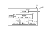
- the schematic block diagram of the rotation sensor unit included in the vehicle of FIG. The schematic block diagram of the transmitter provided in the vehicle of FIG.
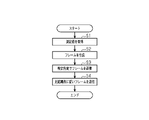
- the flowchart when the transmission control unit of FIG. 3 performs the transmission at a specific angle. A time chart showing the correspondence between the transmission order of frames transmitted by the specific angle transmission of FIG. 5 and the transmission interval of frames.
- the vehicle 10 includes four wheels 11. Each wheel 11 includes a wheel body 12 and a tire 13 mounted on the wheel body 12. Of the wheels 11, the front right wheel will be referred to as FR, the front left wheel will be referred to as FL, the rear right wheel will be referred to as RR, and the rear left wheel will be referred to as RL.
- FR front right wheel
- FL front left wheel
- RR rear right wheel
- RL rear left wheel
- the vehicle 10 is equipped with an anti-lock braking system (hereinafter referred to as ABS) 20.
- the ABS 20 includes an ABS controller 25 and rotation sensor units 21 to 24 corresponding to each of the four wheels 11.
- the rotation sensor units 21 to 24 include a first rotation sensor unit 21, a second rotation sensor unit 22, a third rotation sensor unit 23, and a fourth rotation sensor unit 24.
- the first rotation sensor unit 21 corresponds to the left front wheel FL.
- the second rotation sensor unit 22 corresponds to the right front wheel FR.
- the third rotation sensor unit 23 corresponds to the left rear wheel RL.
- the fourth rotation sensor unit 24 corresponds to the right rear wheel RR.
- the ABS controller 25 includes a processor 28 and a storage unit 29.
- the ABS controller 25 has a timekeeping function. The timekeeping function is realized by, for example, a timer or a counter.
- Examples of the processor 28 include a CPU (Central Processing Unit), a GPU (Graphics Processing Unit), and a DSP (Digital Signal Processor).
- the storage unit 29 includes a RAM (RandomAccessMemory) and a ROM (ReadOnlyMemory).
- the storage unit 29 stores a program code or a command configured to cause the processor 28 to execute the process.
- the ABS controller 25 may be configured by a hardware circuit such as an ASIC (Application Specific Integrated Circuit) or an FPGA (Field Programmable Gate Array).
- the ABS controller 25, which is a processing circuit, may include one or more processors 28 operating according to a computer program, one or more hardware circuits such as ASICs and FPGAs, or a combination thereof.
- ROM and RAM, or computer-readable media include any available medium accessible by a general purpose or dedicated computer.
- each rotation sensor unit 21 to 24 which is a rotation angle detection unit includes a gear 26 that rotates integrally with the wheel 11, and a detector 27 arranged so as to face the outer peripheral surface of the gear 26.
- a plurality of teeth are provided on the outer peripheral surface of the gear 26 at equal-angle intervals.
- the number of teeth of the gear 26 is, for example, 48.
- the detector 27 detects a pulse generated by the rotation of the gear 26.
- the ABS controller 25 is connected to the detector 27.
- the ABS controller 25 obtains the rotation angle of each wheel 11 based on the pulse count value which is the angle detection value of each detector 27. Specifically, the ABS controller 25 counts the rise and fall of the pulse generated in the detector 27 to obtain the pulse count number. The ABS controller 25 divides the obtained pulse count number by the pulse count number obtained while the gear 26 makes one rotation, and calculates the remainder obtained as a result as the pulse count value. Further, by dividing 360 degrees by the pulse count number obtained while the wheel 11 makes one rotation, it is possible to grasp how many times the gear 26 has rotated for each pulse count value 1. From these, the rotation angle of the wheel 11 can be obtained from the pulse count value. The pulse count value is a value in the range of 0 to 95. The ABS controller 25 stores the pulse count value in the storage unit 29 in association with the time.
- the transmission / reception system 30 is mounted on the vehicle 10.
- the transmission / reception system 30 includes a transmitter 31 and a receiver 50 installed on the vehicle body of the vehicle 10.
- the transmitter 31 is mounted on each of the four wheels 11 of the vehicle 10.
- the transmitter 31 is attached to the wheel 11 so as to be arranged in the internal space of the tire 13.
- any one may be used, such as one fixed to the tire valve, one fixed to the wheel body 12, or one fixed to the tire 13.
- the transmitter 31 detects the state of the corresponding tire 13.
- the transmitter 31 wirelessly transmits a frame containing the detected tire 13 information to the receiver 50.
- the transmission / reception system 30 is a system for monitoring the state of the tire 13 by receiving the frame transmitted from the transmitter 31 at the receiver 50.
- each transmitter 31 includes a pressure sensor 32, a temperature sensor 33, an acceleration sensor 34, a transmission control unit 35, a transmission circuit 39, a battery 40, and a transmission antenna 41. ..
- the transmitter 31 is operated by the power supplied from the battery 40.
- the battery 40 may be a primary battery or a power storage device such as a secondary battery or a capacitor.
- the pressure sensor 32 detects the air pressure of the corresponding tire 13.
- the temperature sensor 33 detects the temperature inside the corresponding tire 13.
- the acceleration sensor 34 includes a detection shaft 34a.
- the acceleration sensor 34 detects the acceleration in the direction in which the detection shaft 34a extends.
- the acceleration sensor 34 is mounted on the wheel 11 so that the centrifugal acceleration generated by the rotation of the wheel 11 can be detected.
- the acceleration sensor 34 is mounted on the wheel 11 so that the detection shaft 34a faces in the vertical direction when the transmitter 31 is located at the lowest position of the wheel 11.
- the acceleration sensor 34 may be a uniaxial acceleration sensor 34 or a multi-axis acceleration sensor 34 as long as it can detect at least centrifugal force.
- the transmission control unit 35 includes a processor 36 and a storage unit 37.
- the transmission control unit 35 has a timekeeping function. The timekeeping function is realized by, for example, a timer or a counter. Examples of the processor 36 include a CPU, a GPU, or a DSP.
- the storage unit 37 includes ROM and RAM. The storage unit 37 stores a program code or a command configured to cause the processor 36 to execute the process.
- the transmission control unit 35 may be configured by a hardware circuit such as an ASIC or FPGA.
- the transmission control unit 35 which is a processing circuit, may include one or more processors 36 operating according to a computer program, one or more hardware circuits such as ASICs and FPGAs, or a combination thereof.
- ROM and RAM, or computer-readable media include any available medium accessible by a general purpose or dedicated computer.
- the storage unit 37 stores an ID code indicating unique identification information of each transmitter 31.
- the ID code of the transmitter 31 mounted on the left front wheel FL is FLID
- the ID code of the transmitter 31 mounted on the right front wheel FR is FRID
- the ID code of the transmitter 31 mounted on the left rear wheel RL is Is referred to as RLID
- the ID code of the transmitter 31 mounted on the right rear wheel RR is referred to as RRID.
- the transmission control unit 35 generates a frame.
- the transmission control unit 35 outputs the generated frame to the transmission circuit 39.
- a frame is digital data and is a binary data string.
- the frame is composed of data in the format specified by the protocol.
- the format of the frame includes, for example, a preamble, an ID code, pressure data, temperature data, a status code, and an error detection code.
- the transmission circuit 39 transmits a radio signal modulated according to the frame input from the transmission control unit 35 from the transmission antenna 41. As a result, the transmission circuit 39 transmits the frame.
- the radio signal is, for example, an RF band signal such as a 315 MHz band or a 434 MHz band.
- the transmitter 31 performs steady transmission of transmitting a frame regardless of the rotation angle of the wheel 11 and specific angle transmission of transmitting a frame when it detects that the rotation angle of the wheel 11 is a predetermined specific angle. It is possible to do.
- the predetermined interval is, for example, ten seconds to several tens of seconds.
- the specific angle transmission is performed, for example, when the vehicle 10 is stopped for a predetermined time or longer, and then when the vehicle 10 travels.
- the predetermined time is set to be longer than the time required for changing the position of the wheel 11 such as tire rotation and the time required for replacing the wheel 11.
- the predetermined time is, for example, several tens of minutes to several hours.
- Whether or not the vehicle 10 is traveling can be determined from the acceleration detected by the acceleration sensor 34. As the vehicle speed increases, the centrifugal acceleration acting on the acceleration sensor 34 increases. If the acceleration detected by the acceleration sensor 34 is equal to or greater than the travel determination threshold value, the transmission control unit 35 determines that the vehicle 10 is traveling. On the other hand, if the acceleration detected by the acceleration sensor 34 is less than the threshold value for travel determination, the transmission control unit 35 determines that the vehicle 10 is stopped.
- the travel determination threshold is set to a value larger than the acceleration detected by the acceleration sensor 34 when the vehicle 10 is stopped, in consideration of tolerances and the like.
- the frame is transmitted when it is detected that the rotation angle of the wheel 11 has reached a predetermined specific angle. More specifically, the transmission control unit 35 transmits a frame when a predetermined time (for example, ten seconds to several tens of seconds) has elapsed from the transmission of the previous frame and a specific angle is detected.
- a predetermined time for example, ten seconds to several tens of seconds
- the specific angle include an angle at which the transmitter 31 is at the highest position of the wheel 11 and an angle at which the transmitter 31 is at the lowest position of the wheel.
- step S1 the transmission control unit 35 acquires the measured values from the pressure sensor 32 and the temperature sensor 33.
- step S2 the transmission control unit 35 generates a frame in a predetermined format.
- This frame contains information indicating the measured value acquired in step S1.
- the transmission control unit 35 transmits a frame triggered by the detection of a specific angle.
- the fact that the transmitter 31 has reached a specific angle can be detected by the acceleration detected by the acceleration sensor 34.
- the extending direction of the detection shaft 34a is the same direction as the direction in which the centrifugal force acts regardless of the rotation angle of the wheel 11, and the acceleration sensor 34 detects the centrifugal acceleration regardless of the rotation angle of the wheel 11. To detect.
- the acceleration sensor 34 since the gravitational acceleration always acts in the vertical direction, the acceleration sensor 34 detects the component force of the gravitational acceleration when the detection axis 34a does not face the vertical direction.
- the acceleration detected by the acceleration sensor 34 is the acceleration obtained by adding the gravitational acceleration to the centrifugal acceleration.
- the centrifugal acceleration that changes during one rotation of the wheel 11 is extremely small. Therefore, the acceleration that changes during one rotation of the wheel 11 can be regarded as the gravitational acceleration. Then, from this change in gravitational acceleration, it is possible to detect that the rotation angle of the wheel 11 is a specific angle. When only the gravitational acceleration is considered, the gravitational acceleration changes between +1 [G] and -1 [G] during one rotation of the wheel 11. If the detection shaft 34a faces the vertical direction when the transmitter 31 is in the lowest position, the gravitational acceleration becomes +1 [G] when the transmitter 31 is in the lowest position of the wheel 11, and the transmitter 31 is in the wheel 11.
- the gravitational acceleration becomes -1 [G] when it reaches the highest position of.
- the transmission control unit 35 can transmit a frame triggered by the detection of a specific angle. For example, when the transmission control unit 35 acquires acceleration from the acceleration sensor 34 in a predetermined cycle, the gravitational acceleration changes from an increase to a decrease as the transmitter 31 passes through the lowest position. In this way, it can be said that the transmission control unit 35 can detect that the transmitter 31 has reached a specific angle due to the increase or decrease in the gravitational acceleration.
- the “specific angle” is the rotation angle of the wheel 11 including the allowable range. Due to various factors such as the frequency with which the transmission control unit 35 acquires acceleration from the acceleration sensor 34 and the detection error of the acceleration sensor 34, the rotation angle of the wheels 11 when the frame is actually transmitted is relative to a certain specific angle. May cause an error.
- the "specific angle” does not mean only an angle that completely matches a certain specific angle, but can be said to include a permissible range in which an error is taken into consideration.
- the transmission control unit 35 detects a specific angle.
- the transmission control unit 35 corresponds to the detection unit.
- step S4 the transmission control unit 35 transmits the same frame as the frame transmitted in step S3.
- the frame transmitted in step S4 and the frame transmitted in step S3 have the same data including the preamble, ID code, pressure data, temperature data, status code, and error detection code.
- the transmission control unit 35 transmits the frames a plurality of times at predetermined transmission intervals from the transmission of the first frame F1. ..
- the frame is transmitted three times.
- the three frames F2, F3, and F4 are transmitted after the second frame F2 transmitted after the first frame F1, the third frame F3 transmitted after the second frame F2, and the third frame F3.
- the fourth frame F4 to be made is included.
- the transmission order of frames F1 to F4 and the transmission interval of frames F1 to F4 are associated in advance, and the transmission control unit 35 transmits frames F1 to F4 according to this correspondence.
- the correspondence between the transmission order of the frames F1 to F4 and the transmission interval of the frames F1 to F4 is stored in, for example, the storage unit 37.
- the first frame F1 is transmitted at time T1.
- the transmission interval between the first frame F1 and the second frame F2 transmitted after the first frame F1 is 110 [ms].
- the second frame F2 is transmitted at the time T2 after 110 [ms] has elapsed from the time T1.
- the transmission interval between the second frame F2 and the third frame F3 transmitted after the second frame F2 is 120 [ms].
- the transmission of the third frame F3 is performed at the time T3 after 120 [ms] have elapsed from the time T2.
- the transmission interval between the third frame F3 and the fourth frame F4 transmitted after the third frame F3 is 130 [ms].
- the fourth frame F4 is transmitted at the time T4 after 130 [ms] have elapsed from the time T3.
- 110 [ms] is associated with the second frame F2 to be transmitted second.
- 120 [ms] is associated with the third frame F3 transmitted third.
- 130 [ms] is associated with the fourth frame F4 transmitted fourth.
- the frames following the first transmitted frame are transmitted at different time intervals from each other. More specifically, the transmission interval between two arbitrarily selected frames among all transmitted frames is also different from the transmission interval between any other arbitrarily selected two frames.
- the transmission control unit 35 transmits the second frame F2, the third frame F3, and the fourth frame F4 at the above-mentioned transmission interval, triggered by the transmission of the first frame F1. It can be said that the transmission control unit 35 is configured to transmit frames F1 to F4 a total of four times, triggered by the detection of a specific angle. The frames F1 to F4 are transmitted at different transmission intervals from each other. The above-mentioned transmission interval is an example, and the transmission interval of frames F1 to F4 can be arbitrarily set.
- the transmission control unit 35 corresponds to the transmission unit.
- the receiver 50 includes a receiving circuit 51, a receiving control unit 52, and a receiving antenna 56.
- a display 57 mounted on the vehicle 10 is connected to the reception control unit 52.
- the reception control unit 52 includes a processor 53 and a storage unit 54.
- the reception control unit 52 has a timekeeping function. The timekeeping function is realized by, for example, a timer or a counter. Examples of the processor 53 include a CPU, a GPU, and a DSP.
- the storage unit 54 includes ROM and RAM.
- the storage unit 54 stores a program code or a command configured to cause the processor 53 to execute the process.
- the reception control unit 52 may be configured by a hardware circuit such as an ASIC or FPGA.
- the reception control unit 52 which is a processing circuit, may include one or more processors 53 operating according to a computer program, one or more hardware circuits such as ASICs and FPGAs, or a combination thereof.
- processors 53 operating according to a computer program
- hardware circuits such as ASICs and FPGAs, or a combination thereof.
- ROM and RAM, or computer-readable media include any available medium accessible by a general purpose or dedicated computer.
- the receiving circuit 51 demodulates the radio signal received from each transmitter 31 via the receiving antenna 56 to obtain the data included in the frames F1 to F4.
- the reception circuit 51 outputs data to the reception control unit 52.
- the receiving circuit 51 corresponds to the receiving unit.
- the reception control unit 52 grasps the state of the tire 13, that is, the pressure in the tire 13 and the temperature in the tire 13 based on the data output from the reception circuit 51. When the tire 13 has an abnormality, the reception control unit 52 displays a notification on the display 57.
- the storage unit 54 stores the ID code of the transmitter 31 mounted on each of the four wheels 11. As a result, the transmitter 31 is associated with the receiver 50.
- the storage unit 54 stores the correspondence between the transmission order of the frames F1 to F4 and the transmission interval of the frames F1 to F4. In other words, it can be said that the transmitter 31 transmits the frames F1 to F4 at the transmission interval stored in the storage unit 54 of the receiver 50.
- the receiver 50 it may be desired to specify which of the four wheels 11 the tire 13 the received frames F1 to F4 are related to. For example, when it is desired to display on the display 57 which position the tire 13 has a pressure abnormality generated in one of the four wheels 11, or in the tire 13 corresponding to each position of the wheel 11. You may want to display the pressure on the display 57. In such a case, it is necessary to specify which of the four wheels 11 the received frames F1 to F4 are related to. In other words, the reception control unit 52 needs to associate the ID code of each transmitter 31 with the position of the wheel 11.
- the wheel position specifying process for specifying which of the four wheels 11 each transmitter 31 is mounted on will be described.
- the wheel position specifying process is performed, for example, when the vehicle 10 is put into the started state by the start switch for switching between the started state and the stopped state of the vehicle 10.
- the activated state of the vehicle 10 is a state in which the vehicle 10 can travel by operating the accelerator pedal.
- the stopped state of the vehicle 10 is a state in which the vehicle 10 does not travel even if the accelerator pedal is operated.
- step S11 the reception control unit 52 receives the frames F1 to F4.
- the present embodiment it is assumed that at least two frames out of the four frames F1 to F4 transmitted from one transmitter 31 are received.
- step S12 the reception control unit 52 determines whether or not all of the four frames F1 to F4 have been received. If the determination result in step S12 is affirmative, the reception control unit 52 performs the process of step S21. If the determination result in step S12 is negative, the reception control unit 52 performs the process of step S13.
- step S21 the reception control unit 52 acquires the pulse count value corresponding to the time when the first frame F1 is received.
- the reception control unit 52 acquires a pulse count value corresponding to the time when the first frame F1 is received from the ABS controller 25. Since the pulse count value is stored in the storage unit 29 of the ABS controller 25 in association with the time, the reception control unit 52 can acquire the pulse count value corresponding to the time when the first frame F1 is received. ..
- the reception control unit 52 performs the process of step S16.
- the reception control unit 52 determines which frame F1 to F4 is transmitted from each of the received frames F1 to F4 based on the correspondence between the transmission order and the transmission interval. By making the transmission intervals of the frames F1 to F4 different, the interval of receiving the frames F1 to F4 by the reception control unit 52 can be regarded as the same as the transmission interval.
- the reception interval between the first frame F1 and the second frame F2 is the first frame F1 and the second frame F2. It becomes the same as the transmission interval of.
- the reception interval between the second frame F2 and the third frame F3 is the same as the transmission interval between the second frame F2 and the third frame F3.
- the reception interval between the third frame F3 and the fourth frame F4 is the same as the transmission interval between the third frame F3 and the fourth frame F4.
- the reception interval is 360 [ms]. If the reception control unit 52 receives two frames and the reception interval between the two frames is 360 [ms], the first received frame is the first frame F1 and the last received frame is. It can be determined that it is the fourth frame F4. Similarly, when two frames are received and the reception interval between the two frames is 120 [ms], the first received frame is the second frame F2, and the last received frame is the third frame. It can be determined that it is F3. Similarly, even when the number of received frames is three or more, it is possible to determine the number of the transmitted frame for each received frame by using the reception interval of any two frames. ..
- the reception control unit 52 determines which frame each received frame is transmitted from the correspondence relationship between the transmission order and the transmission interval.
- the reception control unit 52 corresponds to the determination unit.
- the reception control unit 52 derives a specific time.
- the specific time is a time within a predetermined time after the specific angle is detected by the transmitter 31, and is a time associated with the time when the specific angle is detected by the transmitter 31. Since the first frame F1 is transmitted when the detection of a specific angle is triggered, the specific time can be said to be a time within a predetermined time after the first frame F1 is transmitted, and is associated with the time when the first frame F1 is transmitted. It can be said that the time was set.
- the specific time of the present embodiment is the reception time of the first frame F1.
- the reception control unit 52 Since the reception control unit 52 can grasp the order in which each of the received frames F1 to F4 is transmitted, the reception control unit 52 determines the time when the first frame F1 is received when the first frame F1 is received. Set to a specific time. When the reception control unit 52 cannot receive the first frame F1, it estimates the time at which it is assumed that the first frame F1 can be received, and sets the estimated time as the specific time. For example, when the second frame F2 can be received, the time obtained by subtracting 110 [ms] from the reception time of the second frame F2 is the time on which it is assumed that the first frame F1 can be received.
- the time obtained by subtracting 230 [ms] from the reception time of the third frame F3 is the time on which it is assumed that the first frame F1 can be received.
- the time obtained by subtracting 360 [ms] from the reception time of the fourth frame F4 is the time on which it is assumed that the first frame F1 can be received. In this way, even when the first frame F1 cannot be received, the time on which it is assumed that the first frame F1 can be received can be derived.
- the specific time includes a time when the first frame F1 is actually received and a time when it is assumed that the first frame F1 can be received, that is, an estimated reception time.
- the description of "reception time of the first frame F1" includes both the actual reception time and the assumed reception time in principle, unless otherwise specified.
- the reception control unit 52 corresponds to the specific time derivation unit.
- step S15 the reception control unit 52 acquires the pulse count value corresponding to the specific time from the ABS controller 25. Since the pulse count value is stored in the storage unit 29 of the ABS controller 25 in association with the time, the reception control unit 52 can acquire the pulse count value corresponding to the specific time derived in step S14.
- step S16 the reception control unit 52 performs a position specifying process for specifying which of the four wheels 11 each transmitter 31 is mounted on.
- the position specifying process is performed by collecting the pulse count value acquired in step S21 and the pulse count value acquired in step S15.
- the pulse count value acquired in step S21 and the pulse count value acquired in step S15 are both pulse count values acquired at the reception time of the first frame F1.
- the rotation speed of each wheel 11 differs depending on the influence of the differential gear and the like. Therefore, the relative positional relationship of the transmitters 31 mounted on the four wheels 11 changes as the vehicle 10 travels. That is, the rotation angle of each transmitter 31 is synchronized with the rotation angle of the wheel 11 on which the transmitter 31 is mounted, but is synchronized with the rotation angle of the other wheels 11 on which the transmitter 31 is not mounted. do not do. Therefore, when each of the four transmitters 31 transmits the first frame F1 at a specific angle, the rotation angle of each of the four wheels 11 is the corresponding one to the first frame of the four transmitters 31. It is synchronized with the rotation angle when F1 is transmitted.
- each transmitter 31 transmits the first frame F1 at a specific angle
- the pulse count value is acquired through the rotation sensor units 21 to 24 triggered by the reception of the first frame F1
- each transmitter 31 receives the pulse count value.
- the variation in the pulse count value detected by the first rotation sensor unit 21 corresponding to the left front wheel FL is the smallest. Therefore, it can be specified that the FLID transmitter 31 is mounted on the left front wheel FL.
- the reception control unit 52 identifies which of the four wheels 11 the FFID, RLID, and RRID transmitter 31 is mounted on.
- the wheel position specifying process is repeated every time the frames F1 to F4 are received until the correspondence between the positions of all the transmitters 31 and the wheels 11 is specified.
- the reception control unit 52 ends the wheel position specifying process.
- the correspondence between the four ID codes and the positions of the wheels 11 is stored in the storage unit 54 of the reception control unit 52.
- the reception control unit 52 corresponds to a specific unit.
- the reception control unit 52 identifies which of the plurality of wheels 11 each of the transmitters 31 is mounted on, based on the pulse count value obtained at a specific time.
- the specific time is derived from the transmission order of frames F1 to F4.
- the reception time of the first frame F1 is a specific time.
- the transmission intervals of all frames F1 to F4 are set to different intervals. Specifically, among all the frames F1 to F4, the transmission interval between two arbitrarily selected frames is also different from the transmission interval between any other arbitrarily selected two frames. By doing so, the reception control unit 52 can derive the transmission order of the frames F1 to F4 from the correspondence relationship between the transmission order of the frames F1 to F4 and the transmission interval of the frames F1 to F4.
- the transmission order of the frames F1 to F4 can be determined as long as two or more frames F1 to F4 among the frames F1 to F4 transmitted three or more times can be received. Even if at least one of the frames F1 to F4 transmitted three or more times cannot be received, the pulse count value at a specific time can be obtained. In the embodiment, if two frames F1 to F4 among the frames F1 to F4 transmitted four times can be received, a pulse count value at a specific angle can be obtained. Therefore, it is possible to suppress that the time required for specifying the position of the transmitter 31 becomes longer than that of the receiver 50, which cannot obtain the pulse count value when the first transmitted frame cannot be received.
- the reception time of the first frame F1 is set as a specific time.
- the first frame F1 is transmitted at the timing when it is detected that the rotation angle of the wheel 11 has reached a specific angle. Therefore, by setting the reception time of the first frame F1 to a specific time, the variation in the pulse count value tends to be smaller than in the case where the reception time is different from the reception time of the first frame F1. Therefore, the time required to specify the position of the transmitter 31 can be shortened.
- the transmitter 31 transmits frames F1 to F4 at the transmission interval stored in the storage unit 54 of the receiver 50.
- the receiver 50 identifies the position of the transmitter 31 by using the correspondence between the transmission order of the frames F1 to F4 and the transmission interval.
- the transmitter 31 determines which of the plurality of wheels 11 the transmitter 31 is mounted on the receiver 50. Can be specified by. If two or more frames F1 to F4 among the frames F1 to F4 transmitted three or more times can be received, the receiver 50 can specify the position of the transmitter 31, and thus the position of the transmitter 31. It is possible to prevent the time required for identification from becoming long.
- the frames F1 to F4 transmitted multiple times triggered by the detection of a specific angle are all the same data.
- the receiver 50 can specify the transmission order even when the frames F1 to F4 are all the same data.
- the transmission order of the frames can be specified.
- the data length of the frame may become long.
- the frame including the data indicating the transmission order or the data indicating the elapsed time from the detection of the specific angle. No need to send.
- the life of the battery 40 can be extended. Further, it is not necessary to use a frame format that can include data indicating the transmission order and data indicating the elapsed time from the detection of a specific angle.
- Frames F1 to F4 are transmitted at different transmission intervals. Therefore, the position of the transmitter 31 when the frames F1 to F4 are transmitted tends to be different. Depending on the vehicle 10, there may be a null point where the frames F1 to F4 transmitted from each transmitter 31 interfere with each other. When all the frames F1 to F4 are transmitted at the same position, if the position matches the null point, the receiver 50 may not be able to receive all the frames F1 to F4. Since the positions of the transmitters 31 when the frames F1 to F4 are transmitted are different, it is possible to suppress that all the frames F1 to F4 cannot be received due to the null point.
- the transmission / reception system 30 includes the transmitter 31 and the receiver 50 described above. Therefore, it is possible to prevent the time required for specifying the position of the transmitter 31 from becoming long.
- the specific time may be different from the reception time of the first frame F1 as long as it is within a predetermined time from the detection of the specific angle. Although the reception time of the first frame F1 is affected by the time required for reception, there is little deviation from the time when the specific angle is detected. On the other hand, when the specific time is set to a time different from the reception time of the first frame F1, the larger the difference from the reception time of the first frame F1, the greater the influence of the speed of the vehicle 10.
- the transmission time of the fourth frame F4 is 360 [ms] later than the transmission time of the first frame F1. Therefore, the fourth frame F4 is transmitted with a deviation from the specific angle by the angle at which the wheel 11 rotates during 360 [ms].
- the pulse count value varies due to the influence of the speed of the vehicle 10. It may grow larger. Therefore, as the specific time, it is preferable that the time has a small difference from the reception time of the first frame F1. Therefore, the predetermined time is a time within a range in which the position can be specified from the variation of the pulse count value.
- the specific time is not limited to the reception time of frames F1 to F4.
- the specific time may be a time between the first frame F1 and the second frame F2, or a time before the reception time of the first frame F1.
- the reception control unit 52 may derive a specific time from the correspondence relationship between the transmission order of the frames F1 to F4 and the transmission interval of the frames F1 to F4. good. That is, step S12 and step S21 may be omitted from the flowchart shown in FIG.
- the frames F1 to F4 transmitted multiple times triggered by the detection of a specific angle may be different data from each other. For example, when the transmission order and the elapsed time from the detection of a specific angle are included in the frames F1 to F4, these data have different values depending on the transmission order. Even in this case, by transmitting the frames F1 to F4 at different transmission intervals, the reception control unit 52 can specify the transmission order from the transmission intervals.
- the transmitter 31 may detect either the pressure of the tire 13 or the temperature of the tire 13 as the state of the tire 13.
- the angle detection value may be a pulse count value converted into a rotation angle [°].
- the vehicle 10 may be a vehicle provided with a plurality of wheels 11, and may be, for example, a two-wheeled vehicle.
- F1 to F4 ... Frame, 10 ... Vehicle, 11 ... Wheel, 13 ... Tire, 21, 22, 23, 24 ... Rotation sensor unit as rotation angle detection unit, 30 ... Transmission / reception system, 31 ... Transmitter, 35 ... Detection unit And a transmission control unit as a transmission unit, 50 ... a receiver, 51 ... a reception circuit as a reception unit, 52 ... a determination unit, a specific time derivation unit, and a reception control unit as a specific unit, 54 ... a storage unit.
Landscapes
- Engineering & Computer Science (AREA)
- Mechanical Engineering (AREA)
- Computer Networks & Wireless Communication (AREA)
- Arrangements For Transmission Of Measured Signals (AREA)
Priority Applications (6)
| Application Number | Priority Date | Filing Date | Title |
|---|---|---|---|
| KR1020227035017A KR20220150961A (ko) | 2020-11-19 | 2020-11-19 | 수신기, 송신기 및 송수신 시스템 |
| US17/995,995 US20230271463A1 (en) | 2020-11-19 | 2020-11-19 | Receiver, transmitter, and transmission-reception system |
| PCT/JP2020/043243 WO2022107287A1 (ja) | 2020-11-19 | 2020-11-19 | 受信機、送信機及び送受信システム |
| JP2022563505A JPWO2022107287A1 (https=) | 2020-11-19 | 2020-11-19 | |
| CN202080099740.9A CN115461233A (zh) | 2020-11-19 | 2020-11-19 | 接收机、发送机以及收发系统 |
| EP20962450.1A EP4119363A4 (en) | 2020-11-19 | 2020-11-19 | RECEIVER, TRANSMITTER AND TRANSMITTER/RECEIVER SYSTEM |
Applications Claiming Priority (1)
| Application Number | Priority Date | Filing Date | Title |
|---|---|---|---|
| PCT/JP2020/043243 WO2022107287A1 (ja) | 2020-11-19 | 2020-11-19 | 受信機、送信機及び送受信システム |
Publications (1)
| Publication Number | Publication Date |
|---|---|
| WO2022107287A1 true WO2022107287A1 (ja) | 2022-05-27 |
Family
ID=81708550
Family Applications (1)
| Application Number | Title | Priority Date | Filing Date |
|---|---|---|---|
| PCT/JP2020/043243 Ceased WO2022107287A1 (ja) | 2020-11-19 | 2020-11-19 | 受信機、送信機及び送受信システム |
Country Status (6)
| Country | Link |
|---|---|
| US (1) | US20230271463A1 (https=) |
| EP (1) | EP4119363A4 (https=) |
| JP (1) | JPWO2022107287A1 (https=) |
| KR (1) | KR20220150961A (https=) |
| CN (1) | CN115461233A (https=) |
| WO (1) | WO2022107287A1 (https=) |
Cited By (2)
| Publication number | Priority date | Publication date | Assignee | Title |
|---|---|---|---|---|
| WO2025047769A1 (ja) * | 2023-08-31 | 2025-03-06 | Primetals Technologies Japan株式会社 | 通信機、計測装置、スピンドル装置、圧延設備及び通信機の運転方法 |
| WO2025197694A1 (ja) * | 2024-03-21 | 2025-09-25 | 株式会社デンソー | 車輪位置検出装置、タイヤ空気圧監視システム |
Citations (2)
| Publication number | Priority date | Publication date | Assignee | Title |
|---|---|---|---|---|
| JP2011527971A (ja) | 2008-09-26 | 2011-11-10 | コンチネンタル オートモーティヴ ゲゼルシャフト ミット ベシュレンクテル ハフツング | 車両における少なくとも1つのホイールのロケーティングのための方法、センサ、検出器及びシステム |
| JP2012240615A (ja) * | 2011-05-23 | 2012-12-10 | Nissan Motor Co Ltd | タイヤ空気圧モニター装置 |
Family Cites Families (6)
| Publication number | Priority date | Publication date | Assignee | Title |
|---|---|---|---|---|
| FR2851106B1 (fr) * | 2003-02-06 | 2005-03-18 | Siemens Vdo Automotive | Procede d'emission de donnees pour un systeme de surveillance de la pression des pneumatiques d'un vehicule |
| JP4735185B2 (ja) * | 2005-10-21 | 2011-07-27 | 株式会社デンソー | 車輪位置検出装置およびそのタイヤ空気圧検出装置 |
| JP5477369B2 (ja) * | 2011-12-27 | 2014-04-23 | 株式会社デンソー | 車輪位置検出装置およびそれを備えたタイヤ空気圧検出装置 |
| US9333814B2 (en) * | 2013-08-22 | 2016-05-10 | Schrader Electronics Ltd. | System and method for performing auto-location of a tire pressure monitoring sensor arranged with a vehicle wheel using confidence interval analysis and rollback events |
| JP2017001416A (ja) * | 2015-06-04 | 2017-01-05 | 株式会社デンソー | 車輪位置検出装置およびそれを備えたタイヤ空気圧検出システム |
| WO2018066397A1 (ja) * | 2016-10-05 | 2018-04-12 | 株式会社オートネットワーク技術研究所 | タイヤ空気圧検出システム、車体側装置及びタイヤ側装置 |
-
2020
- 2020-11-19 JP JP2022563505A patent/JPWO2022107287A1/ja active Pending
- 2020-11-19 US US17/995,995 patent/US20230271463A1/en not_active Abandoned
- 2020-11-19 KR KR1020227035017A patent/KR20220150961A/ko not_active Ceased
- 2020-11-19 WO PCT/JP2020/043243 patent/WO2022107287A1/ja not_active Ceased
- 2020-11-19 CN CN202080099740.9A patent/CN115461233A/zh active Pending
- 2020-11-19 EP EP20962450.1A patent/EP4119363A4/en not_active Withdrawn
Patent Citations (2)
| Publication number | Priority date | Publication date | Assignee | Title |
|---|---|---|---|---|
| JP2011527971A (ja) | 2008-09-26 | 2011-11-10 | コンチネンタル オートモーティヴ ゲゼルシャフト ミット ベシュレンクテル ハフツング | 車両における少なくとも1つのホイールのロケーティングのための方法、センサ、検出器及びシステム |
| JP2012240615A (ja) * | 2011-05-23 | 2012-12-10 | Nissan Motor Co Ltd | タイヤ空気圧モニター装置 |
Cited By (3)
| Publication number | Priority date | Publication date | Assignee | Title |
|---|---|---|---|---|
| WO2025047769A1 (ja) * | 2023-08-31 | 2025-03-06 | Primetals Technologies Japan株式会社 | 通信機、計測装置、スピンドル装置、圧延設備及び通信機の運転方法 |
| WO2025046826A1 (ja) * | 2023-08-31 | 2025-03-06 | Primetals Technologies Japan株式会社 | 通信機、計測装置、スピンドル装置、圧延設備及び通信機の運転方法 |
| WO2025197694A1 (ja) * | 2024-03-21 | 2025-09-25 | 株式会社デンソー | 車輪位置検出装置、タイヤ空気圧監視システム |
Also Published As
| Publication number | Publication date |
|---|---|
| KR20220150961A (ko) | 2022-11-11 |
| CN115461233A (zh) | 2022-12-09 |
| EP4119363A4 (en) | 2023-06-21 |
| US20230271463A1 (en) | 2023-08-31 |
| JPWO2022107287A1 (https=) | 2022-05-27 |
| EP4119363A1 (en) | 2023-01-18 |
Similar Documents
| Publication | Publication Date | Title |
|---|---|---|
| WO2022107287A1 (ja) | 受信機、送信機及び送受信システム | |
| CN109153297B (zh) | 接收器 | |
| JP7012092B2 (ja) | タイヤ状態監視システム、送信機及び受信機 | |
| JP6617219B2 (ja) | 送信機、受信機、及び、送受信システム | |
| WO2016190371A1 (ja) | 車輪位置特定装置 | |
| JP7419551B2 (ja) | 輪位置特定システム、及び輪位置特定装置 | |
| JP7002561B2 (ja) | タイヤ状態監視システム、送信機及び受信機 | |
| CN109153296B (zh) | 接收器及发送器单元 | |
| CN109153298B (zh) | 接收器及发送器单元 | |
| WO2025141679A1 (ja) | 送信機、受信機、送受信システム及び輪位置判定方法 | |
| WO2024047690A1 (ja) | 輪位置特定装置、輪位置特定システム、及び輪位置特定方法 | |
| WO2023026455A1 (ja) | 輪位置特定システム、輪位置特定装置、及び輪位置特定方法 |
Legal Events
| Date | Code | Title | Description |
|---|---|---|---|
| 121 | Ep: the epo has been informed by wipo that ep was designated in this application |
Ref document number: 20962450 Country of ref document: EP Kind code of ref document: A1 |
|
| ENP | Entry into the national phase |
Ref document number: 20227035017 Country of ref document: KR Kind code of ref document: A |
|
| ENP | Entry into the national phase |
Ref document number: 2022563505 Country of ref document: JP Kind code of ref document: A |
|
| ENP | Entry into the national phase |
Ref document number: 2020962450 Country of ref document: EP Effective date: 20221012 |
|
| NENP | Non-entry into the national phase |
Ref country code: DE |