WO2022102656A1 - 画像処理装置および工作機械 - Google Patents
画像処理装置および工作機械 Download PDFInfo
- Publication number
- WO2022102656A1 WO2022102656A1 PCT/JP2021/041336 JP2021041336W WO2022102656A1 WO 2022102656 A1 WO2022102656 A1 WO 2022102656A1 JP 2021041336 W JP2021041336 W JP 2021041336W WO 2022102656 A1 WO2022102656 A1 WO 2022102656A1
- Authority
- WO
- WIPO (PCT)
- Prior art keywords
- tool
- edge
- camera
- image
- unit
- Prior art date
- Legal status (The legal status is an assumption and is not a legal conclusion. Google has not performed a legal analysis and makes no representation as to the accuracy of the status listed.)
- Ceased
Links
Images







Classifications
-
- B—PERFORMING OPERATIONS; TRANSPORTING
- B23—MACHINE TOOLS; METAL-WORKING NOT OTHERWISE PROVIDED FOR
- B23Q—DETAILS, COMPONENTS, OR ACCESSORIES FOR MACHINE TOOLS, e.g. ARRANGEMENTS FOR COPYING OR CONTROLLING; MACHINE TOOLS IN GENERAL CHARACTERISED BY THE CONSTRUCTION OF PARTICULAR DETAILS OR COMPONENTS; COMBINATIONS OR ASSOCIATIONS OF METAL-WORKING MACHINES, NOT DIRECTED TO A PARTICULAR RESULT
- B23Q17/00—Arrangements for observing, indicating or measuring on machine tools
- B23Q17/24—Arrangements for observing, indicating or measuring on machine tools using optics or electromagnetic waves
- B23Q17/2452—Arrangements for observing, indicating or measuring on machine tools using optics or electromagnetic waves for measuring features or for detecting a condition of machine parts, tools or workpieces
- B23Q17/2457—Arrangements for observing, indicating or measuring on machine tools using optics or electromagnetic waves for measuring features or for detecting a condition of machine parts, tools or workpieces of tools
-
- G—PHYSICS
- G06—COMPUTING OR CALCULATING; COUNTING
- G06T—IMAGE DATA PROCESSING OR GENERATION, IN GENERAL
- G06T7/00—Image analysis
- G06T7/50—Depth or shape recovery
- G06T7/55—Depth or shape recovery from multiple images
-
- B—PERFORMING OPERATIONS; TRANSPORTING
- B23—MACHINE TOOLS; METAL-WORKING NOT OTHERWISE PROVIDED FOR
- B23Q—DETAILS, COMPONENTS, OR ACCESSORIES FOR MACHINE TOOLS, e.g. ARRANGEMENTS FOR COPYING OR CONTROLLING; MACHINE TOOLS IN GENERAL CHARACTERISED BY THE CONSTRUCTION OF PARTICULAR DETAILS OR COMPONENTS; COMBINATIONS OR ASSOCIATIONS OF METAL-WORKING MACHINES, NOT DIRECTED TO A PARTICULAR RESULT
- B23Q17/00—Arrangements for observing, indicating or measuring on machine tools
- B23Q17/24—Arrangements for observing, indicating or measuring on machine tools using optics or electromagnetic waves
- B23Q17/248—Arrangements for observing, indicating or measuring on machine tools using optics or electromagnetic waves using special electromagnetic means or methods
- B23Q17/249—Arrangements for observing, indicating or measuring on machine tools using optics or electromagnetic waves using special electromagnetic means or methods using image analysis, e.g. for radar, infrared or array camera images
-
- G—PHYSICS
- G06—COMPUTING OR CALCULATING; COUNTING
- G06T—IMAGE DATA PROCESSING OR GENERATION, IN GENERAL
- G06T7/00—Image analysis
- G06T7/0002—Inspection of images, e.g. flaw detection
- G06T7/0004—Industrial image inspection
- G06T7/0008—Industrial image inspection checking presence/absence
-
- G—PHYSICS
- G06—COMPUTING OR CALCULATING; COUNTING
- G06T—IMAGE DATA PROCESSING OR GENERATION, IN GENERAL
- G06T7/00—Image analysis
- G06T7/10—Segmentation; Edge detection
- G06T7/13—Edge detection
-
- H—ELECTRICITY
- H04—ELECTRIC COMMUNICATION TECHNIQUE
- H04N—PICTORIAL COMMUNICATION, e.g. TELEVISION
- H04N23/00—Cameras or camera modules comprising electronic image sensors; Control thereof
- H04N23/60—Control of cameras or camera modules
- H04N23/695—Control of camera direction for changing a field of view, e.g. pan, tilt or based on tracking of objects
-
- G—PHYSICS
- G01—MEASURING; TESTING
- G01B—MEASURING LENGTH, THICKNESS OR SIMILAR LINEAR DIMENSIONS; MEASURING ANGLES; MEASURING AREAS; MEASURING IRREGULARITIES OF SURFACES OR CONTOURS
- G01B11/00—Measuring arrangements characterised by the use of optical techniques
- G01B11/002—Measuring arrangements characterised by the use of optical techniques for measuring two or more coordinates
Definitions
- the present invention relates to a technique for managing a tool shape in a machine tool.
- Machine tools include equipment that cuts the work into a desired shape and equipment that stacks metal powder and the like to make the work.
- a machine tool for cutting is equipped with a turning center that processes a workpiece by applying a cutting tool to a rotating workpiece and a machining center that processes the workpiece by applying a rotating cutting tool to the workpiece.
- the tool is fixed to the tool holding part such as the spindle or the tool post.
- the machine tool processes the work while moving the tool post and the like according to the processing program prepared in advance and selecting the tool to be applied to the work.
- tool shape data is downloaded from the tool manufacturer's website and input to the machine tool to register the tool ID and tool shape in association with each other.
- a registration method has a heavy work load and a heavy confirmation burden for preventing input errors.
- the image processing apparatus has an imaging execution unit that captures a first partial image including a part of a tool by a camera, and a next imaging position based on the partial shape of the tool included in the first partial image. It is provided with a position specifying unit for specifying a position, and a position control unit for changing the relative position of the tool and the camera to the specified imaging position.
- the imaging execution unit captures a second partial image including a part of the tool at the next imaging position.
- the image processing apparatus is the next time based on (1) a first partial image including a part of the tool by a camera and (2) a partial shape of the tool included in the first partial image.
- a receiver that specifies the imaging position changes the relative position of the tool and camera to the identified imaging position, and includes a part of the imaged tool, and a receiver that receives the first part image of the tool.
- a part of the first contour data is extracted, and a part of the second contour data of the tool is extracted from the second part image, and the tool shape data of the tool is obtained based on the first contour data and the second contour data. It includes an image processing unit to generate.
- the machine tool includes a camera, a tool holding unit to which a tool can be mounted, a machining control unit for machining a workpiece with a tool according to a machining program, and a first portion including a part of the tool with a camera.
- the relative position of the tool and the camera is changed between the image pickup execution unit that captures the image, the position specifying unit that specifies the next imaging position based on the partial shape of the tool included in the first partial image, and the next imaging position. It is equipped with a position control unit.
- the imaging execution unit captures a second partial image including a part of the tool at the next imaging position.
- FIG. 3 is a first schematic diagram showing a position control method when a second edge point is detected in the third region in the second modification.
- 2 is a second schematic diagram showing a position control method when a second edge point is detected in the third region in the second modification.
- FIG. 3 is a first schematic diagram showing a position control method when a second edge point is detected in the sixth region in the second modification.
- 2 is a second schematic diagram showing a position control method when a second edge point is detected in the sixth region in the second modification.
- FIG. 1 is an external view of the machine tool 100.
- the machine tool 100 in the present embodiment is a multi-tasking machine that processes a workpiece arranged in a machining area 200.
- the work is fixed to the holding portion 104 and cut by a tool 102 attached to another holding portion, the spindle.
- the holding portion 104 that holds the work is rotationally driven by a drive mechanism.
- the lower lighting device 108 illuminates the tool 102, and the upper camera 106 images the tool 102.
- the tool shape recognition described later is executed based on the image pickup result at this time.
- the configuration of the tool recognition area 210 will be described in more detail in relation to FIG. 2 below.
- the machine tool 100 includes a cover 202 that blocks the outside.
- the cover 202 comprises a door 204.
- the user opens the door 204 to attach the work to the machined area 200 and take out the work from the machined area 200.
- the operation panel 206 receives various operations on the machine tool 100 from the user.
- the operation panel 206 is connected to the image processing device 110.
- the machine tool 100 main body and the image processing device 110 are connected via a wired cable.
- the image processing device 110 may be formed inside the machine tool 100, for example, as an internal device of the operation panel 206.
- the tool storage unit 130 stores a plurality of tools 102.
- a tool 102 is acquired from a plurality of tools 102 stored in the tool storage unit 130 by a tool changer (described later), and the tool 102 is mounted on the spindle.
- a tool changer described later
- the X-axis and the Y-axis are set in the horizontal direction and the Z-axis is set in the vertical direction.
- the Y-axis direction corresponds to the axial direction of the spindle and the work.
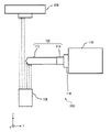
- FIG. 2 is a schematic diagram showing the positional relationship between the tool 102, the camera 106, and the lighting device 108 in the tool recognition area 210.
- the tool 102 includes a blade portion 112 used for machining a work and a shank portion 114 which is a portion fixed to a holder 118 of the spindle 116.
- the spindle 116 is configured to be rotatable and movable while holding the tool 102. Further, the spindle 116, which is also a holding portion, can rotate the holding tool.
- the camera 106 is provided with an image sensor (image sensor) such as CMOS (Complementary Metal Oxide Semiconductor) and CCD (Charge-Coupled Device).
- image sensor image sensor
- the camera 106 takes an image of the tool 102 attached to the spindle 116 from above (Z-axis direction).
- the camera 106 is fixed in the tool recognition area 210.
- the spindle 116 moves the tool 102 in the horizontal direction (XY direction), so that a plurality of points of the tool 102 can be imaged.
- the lighting device 108 is fixed to the lower part so as to face the camera 106.
- the illuminating device 108 illuminates the tool 102 from below. Due to the transmitted illumination by the illuminating device 108, the camera 106 can acquire a high-contrast captured image in which the contour position of the tool 102 can be easily grasped.
- the user When newly registering the tool 102, the user sets the tool registration mode on the operation panel 206 and attaches the tool 102 to the spindle 116. Next, enter an arbitrary tool ID.
- the spindle 116 moves and rotates the tool 102, and the fixed camera 106 automatically captures the tool 102 from various positions and directions.
- the tool shape is recognized from a large number of captured images obtained by the camera 106, and the tool ID and the tool shape are registered in association with each other. With such a control method, the tool shape can be automatically registered. The details of the tool shape recognition method will be described later.
- the camera 106 in this embodiment has a resolution of about 1 million pixels (1224 ⁇ 1024).
- the imaging range is about 300 mm ⁇ 300 mm.
- the camera 106 can acquire up to 80 captured images per second.
- FIG. 3 is a hardware configuration diagram of the machine tool 100 and the image processing device 110.
- the machine tool 100 includes an operation control device 120, a machining control unit 122, a machining device 124, a tool changing unit 126, and a tool storage unit 130.
- the machining control unit 122 that functions as a numerical control device transmits a control signal to the machining device 124 according to the machining program.
- the machining apparatus 124 moves the spindle 116 according to the instruction from the machining control unit 122 to machine the workpiece.
- the operation control device 120 includes the operation panel 206 and controls the machining control unit 122.
- the tool storage unit 130 stores the tool.
- the tool changing unit 126 corresponds to a so-called ATC (Automatic Tool Changer).
- the tool changing unit 126 takes out the tool from the tool storage unit 130 according to the changing instruction from the machining control unit 122, and exchanges the tool on the spindle 116 with the taken out tool.
- the image processing device 110 mainly performs image processing such as tool shape recognition. As described above, the image processing device 110 may be configured as a part of the operation control device 120.
- FIG. 4 is a functional block diagram of the image processing device 110.
- Each component of the image processing device 110 includes a CPU (Central Processing Unit), a computing unit such as various computer processors, a storage device such as a memory and a storage device, hardware including a wired or wireless communication line connecting them, and a storage device. It is stored in and realized by software that supplies processing instructions to the arithmetic unit.
- the computer program may be composed of a device driver, an operating system, various application programs located on the upper layer thereof, and a library that provides common functions to these programs.
- Each block described below shows a block for each function, not a configuration for each hardware.
- the operation control device 120 and the processing control unit 122 are also stored in a computer such as a processor, a storage device such as a memory and a storage device, hardware including a wired or wireless communication line connecting them, and a storage device.
- the software or program that supplies the processing instructions may be realized on an operating system separate from the image processing unit 110.
- the image processing device 110 includes a user interface processing unit 140, a data processing unit 142, and a data storage unit 144.
- the user interface processing unit 140 is in charge of processing related to the user interface, such as image display and audio output, in addition to accepting operations from the user.
- the data processing unit 142 executes various processes based on the data acquired by the user interface processing unit 140 and the data stored in the data storage unit 144.
- the data processing unit 142 also functions as an interface between the user interface processing unit 140 and the data storage unit 144.
- the data storage unit 144 stores various programs and setting data.
- the user interface processing unit 140 includes an input unit 146 and an output unit 148.
- the input unit 146 receives input from the user via a hard device such as a touch panel or a handle.
- the output unit 148 provides various information to the user via an image display or an audio output.
- the input unit 146 includes an ID reception unit 150 that accepts input of a tool ID.
- the data processing unit 142 includes an image pickup execution unit 152, a position identification unit 154, a position control unit 156, a shape reproduction unit 158, a first edge detection unit 160, a second edge detection unit 162, an image conversion unit 164, a tool registration unit 166, and a tool registration unit 166. Includes a movable adjustment unit 168.
- the image pickup execution unit 152 instructs the camera 106 to acquire the captured image.
- the position specifying unit 154 calculates the moving direction of the spindle 116 at the time of imaging of the tool 102 by the method described later.
- the position control unit 156 moves the spindle 116 when the tool 102 is imaged.
- the shape reproduction unit 158 generates "tool shape data" which is data showing the three-dimensional shape of the tool 102 based on the captured image.
- the first edge detection unit 160 detects a "first edge point” indicating the contour position of the tool 102.
- the second edge detection unit 162 also detects a "second edge point” indicating the contour position of the tool 102.
- the image conversion unit 164 changes the resolution of the captured image.
- the tool registration unit 166 associates the tool ID with the tool shape data and registers them in the data storage unit 144.
- the tool ID and the tool shape data may be provided from the image processing device 110 to the operation control device 120.
- the movable adjustment unit 168 is a so-called interference check module, and specifies the movable range (movable range) of the spindle 116 based on the type of the machine tool 100, the shape of the work, and the tool shape data of the tool 102 in use. ..
- the position where the spindle 116 interferes with another object such as a work differs depending on the shape and size of the tool 102.
- the movable adjustment unit 168 specifies the movable range of the spindle 116 according to the tool in use based on the tool shape data.
- the machine tool 100 moves the spindle 116 within the movable range of the spindle 116.
- FIG. 5 is a schematic diagram showing the positional relationship between the tool 102 and the imaging region 170.
- the imaging region 170 is located directly below the light receiving surface of the camera 106.
- the camera 106 captures an object within the range of the imaging region 170.
- the position control unit 156 inserts the tool 102 into the imaging region 170 by moving the spindle 116. Since the image pickup area 170 is smaller than the tool 102, it is not possible to image the entire tool 102 at one time.
- the lens of the camera 106 is enlarged in order to increase the imaging area 170, the cost of the camera 106 will increase. Further, when a large camera 106 is installed in the tool recognition area 210, the space in the machining area 200 is compressed, which is not preferable. Therefore, in the present embodiment, a method is adopted in which the tool 102 is imaged in a plurality of times by a relatively small camera 106, and the shape of the entire tool 102 is recognized based on the plurality of captured images.
- the tool shape recognition process (hereinafter referred to as “shape recognition process”) takes time.
- the tool 102 is efficiently moved so as not to acquire a captured image that is unnecessary for recognizing the tool shape, specifically, a captured image that does not show the outline of the tool 102. I need to let you.
- the captured image obtained by capturing a part of the tool 102 by the camera 106 is referred to as a “partial image”.
- FIG. 6 is a schematic diagram showing the relationship between the tool 102 and the partial image.
- the position control unit 156 moves the tool 102 (spindle 116) at a constant speed in the negative Y-axis direction, that is, in the direction in which the imaging region 170 moves away from the tip side of the tool 102.
- the image pickup execution unit 152 constantly monitors the image pickup area 170.
- the live view image in the imaging region 170 is transmitted from the camera 106 to the image processing device 110.
- the imaging execution unit 152 instructs the camera 106 to acquire the captured image (partial image).
- the camera 106 receives an instruction, the camera 106 acquires the first partial image and fixes it in the memory.
- the partial image P1 is first acquired.
- the position control unit 156 further moves the tool 102 (main shaft 116) in the negative direction of the Y axis.
- the position control unit 156 slightly moves the spindle 116 in the negative direction of the X-axis so that the contour of the tool 102 does not deviate from the imaging region 170 (details will be described later).
- the image pickup execution unit 152 instructs the camera 106 to acquire the partial image, and the camera 106 saves the second partial image P2 in the memory. In this way, the position control unit 156 appropriately moves the main shaft 116 to the left and right (X direction), and gradually moves the main shaft 116 in the negative direction of the Y axis.
- the image pickup execution unit 152 instructs the camera 106 to take an image (acquisition of a partial image) in accordance with the movement of the spindle 116, and the partial images P1 to P8 are acquired. Based on the plurality of partial images P1 to P8, the shape reproduction unit 158 generates the contour of the tool 102, that is, the tool shape data of the tool 102. By appropriately moving the spindle 116, the contour of the tool 102 can be appropriately recognized as an image while reducing the number of times a partial image is acquired.
- FIG. 7 is a flowchart showing the process of tool registration.
- the tool registration is executed after the user inputs the tool ID.
- the position control unit 156 sets the rotation angle (eg, 0 degrees) of the spindle 116 (S10).
- the rotation angle of the spindle 116 is referred to as a "spindle rotation angle".
- the position control unit 156 moves the spindle 116 in the XY directions, and the imaging execution unit 152 executes the shape recognition process by acquiring a plurality of partial images (S12).
- the details of the shape recognition process will be described later in relation to FIG. 8 below.
- the contour of the tool 102 is specified as point sequence data at the set spindle rotation angle.
- the process returns to S10 and the next rotation angle (example: 12 degrees) is set.
- the shape reproduction unit 158 obtains tool shape data indicating the three-dimensional shape of the tool 102 from the point sequence data obtained for the plurality of spindle rotation angles. Generate (S16).
- the tool registration unit 166 associates the tool ID with the tool shape data and registers them in the data storage unit 144 (S18).
- FIG. 8 is a flowchart showing the shape recognition process in S12 of FIG. 7.
- the position control unit 156 moves the main axis 116 in the negative direction of the Y axis, and the image pickup execution unit 152 acquires a partial image (S20).
- the first edge detection unit 160 recognizes the external position of the tool 102 in the partial image by detecting the first edge point indicating the contour of the tool 102 from the partial image (described later in relation to FIG. 9) (S22).
- the position specifying unit 154 specifies the next imaging position, in other words, the moving direction of the spindle 116, based on the partial image of the tool 102 (S24). The method of specifying the moving direction will be described later in relation to FIG.
- the position control unit 156 moves the tool 102 (spindle 116) in the moving direction specified in S24 (S28).
- the spindle 116 is moved in the negative direction of the Y axis by a predetermined distance, imaging is completed (Y in S26), and the process shifts to S14 in FIG.
- the shape recognition process is a process of S22 for recognizing the contour of the tool 102 as an image (hereinafter referred to as "outer shape recognition process”) and a process of S24 for determining the next movement direction of the tool 102. (Hereinafter referred to as “direction specifying process”) is included.
- the external shape recognition process and the direction specifying process will be described.
- FIG. 9 shows a partial image 290 when the outer shape recognition process is executed.
- FIG. 10 is a diagram showing a first edge point image 190.
- the first edge detection unit 160 sets the scanning line 180a in the positive direction of the X-axis, and is located at the boundary between the dark region 182 (silhouette region where the tool 102 exists) and the bright region 184 (region where the tool 102 does not exist). Is detected as the first edge point 192.
- the first edge detection unit 160 detects a plurality of first edge points 192 while shifting the scanning lines 180a at a constant pitch.
- the first edge detection unit 160 sets the scanning line 180b in the negative direction of the Y axis, and detects the first edge point 192 located at the boundary between the dark region 182 and the bright region 184.
- the first edge detection unit 160 detects a plurality of first edge points 192 while shifting the scanning lines 180b at a constant pitch.
- the first edge detection unit 160 sets the scanning line 180c in the positive direction of the Y axis, and detects the first edge point 192 located at the boundary between the dark region 182 and the bright region 184.
- the first edge detection unit 160 detects a plurality of first edge points 192 while shifting the scanning lines 180c at a constant pitch.
- the processing time required for the external shape recognition processing per partial image is about 200 to 250 milliseconds.
- FIG. 11 shows a partial image 290 when the direction specifying process is executed.
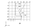
- FIG. 12 is a diagram showing a second edge point image 260.
- the image conversion unit 164 sets the resolution of the partial image 290 to a low resolution of 1/8 during the direction specifying process. The reason for lowering the resolution is to reduce the load and speed of the direction specifying process by suppressing the number of pixels to be processed. It is desirable to use a high-resolution partial image 290 for the shape recognition process to recognize the shape of the tool 102, but it is sufficient for the direction identification process to specify the next imaging position, so a person who uses a low-resolution partial image 290. Is appropriate.
- a reference point 250 is set at a predetermined position of the partial image 290.
- the reference point 250 is set at the center of the partial image.
- an arbitrary reference line 252 passing through the reference point 250 is set.
- the reference line 252 in the present embodiment is set in the first quadrant in the XY plane when the reference point 250 is the origin.
- the second edge detection unit 162 sets the scanning line 254a in the positive direction of the X-axis, and detects a point located at the boundary between the dark region 182 and the bright region 184 as the second edge point 194.
- the second edge detection unit 162 detects a plurality of second edge points 194 while shifting the scanning lines 254a at a constant pitch.
- the second edge detection unit 162 sets the scanning line 254b in the negative direction of the X-axis, and detects a point located at the boundary between the dark region 182 and the bright region 184 as the second edge point 194.
- the second edge detection unit 162 detects a plurality of second edge points 194 while shifting the scanning lines 254b at a constant pitch.
- the second edge detection unit 162 sets the scanning line 254c in the negative direction of the Y axis, and detects a plurality of second edge points 194 in the same manner while shifting the scanning line 254c at a constant pitch.
- the second edge detection unit 162 sets the scanning line 254d in the positive direction of the Y axis, and detects a plurality of second edge points 194 while shifting the scanning line 254d at a constant pitch.
- the position specifying unit 154 sets a verification line 262 connecting the reference point 250 and the second edge point 194.
- the position specifying unit 154 calculates the angle formed by the verification line 262 and the reference line 252 (hereinafter referred to as "edge angle"), and sets the second edge point 194A at which the edge angle is the minimum as the "selected second edge point". Identify.
- the edge angle becomes the minimum.
- the position specifying unit 154 determines the next imaging position based on the verification line 262A at this time.
- the second edge point 194A (selected second edge point) selected by the position specifying portion 154 based on the edge angle is on the side far from the tip of the tool 102, in other words, the second edge point image. It is set on the root side of the tool 102 when viewed from the reference point 250 set at 260. Subsequently, the position specifying portion 154 is located at the lower half of the upper and lower positions (upper: root side of the tool 102, lower: tip side of the tool 102) in the tool length direction (Y-axis direction in FIG. 12) of the tool 102. The next imaging position is determined so that the second edge point 194A moves to the tip side of the tool 102).
- the position specifying unit 154 determines the next imaging position so that the second edge point 194A moves toward the center side in the tool radial direction (X-axis direction in FIG. 12) of the tool 102.
- the position specifying portion 154 Moves the tool 102 along the movement vector 264 (negative direction on the Y axis and positive direction on the X axis) so that the second edge point 194A (selected second edge point) moves downward and toward the center.
- the relative positions of 170 and the tool 102 are changed.
- the position specifying unit 154 moves the tool 102 (spindle 116) along the verification line 262A in the direction shown by the movement vector 264 shown in FIG.
- the Y component (insertion direction) of the movement vector 264 of the tool 102 may be constant. That is, the position control unit 156 adjusts the size of the X component of the movement vector 264 of the tool 102 according to the size of the minimum edge angle.
- the second edge point 194A point showing the contour line moves toward the center in the next partial image 290.
- the processing time required for the direction specifying processing per partial image is about 10 to 20 milliseconds.
- FIG. 13 is a diagram showing tool shape data of the tool 102.
- the position control unit 156 sets the spindle rotation angle centered on the Y-axis of the tool 102, and then moves the tool 102 in the negative direction of the Y-axis while moving the tool 102 in the X-axis direction based on the edge angle. Let me.
- the outer shape of the tool 102 is specified by acquiring the partial image 290 in the imaging region 170 and detecting the first edge point 192 from the partial image 290. After detecting the first edge point 192, the next imaging position is adjusted by detecting the second edge point 194. A plurality of partial images are acquired for one spindle rotation angle.
- the position control unit 156 rotates the tool 102 by 12 degrees, and performs the same processing for the next spindle rotation angle.
- the shape reproduction unit 158 generates the tool shape data shown in FIG. 13, that is, the point sequence data indicating the three-dimensional shape of the tool 102 by integrating the point sequence data of each partial image 290.
- the image processing device 110 and the machine tool 100 have been described above based on the embodiments.
- the user mounts the tool 102 on the spindle 116, and after inputting the tool ID, the tool shape data is automatically generated, and the tool ID and the tool shape data are registered in association with each other.
- the number of tools 102 registered in the tool storage unit 130 may be several tens. Therefore, automating the registration of tool shape data has a great effect of improving the work efficiency of the machine tool 100.
- a small camera 106 that captures only a part of the tool 102 is used.
- the use of the small camera 106 suppresses the cost of the camera 106 and also contributes to the space saving of the processing area 200.
- the partial image 290 which is unnecessary for recognizing the shape of the tool 102, is an image in which the outline of the tool 102 is not reflected.
- the position specifying unit 154 controls the partial image to always capture the outer shape of the tool 102 by adjusting the amount of movement of the camera 106 in the X-axis direction based on the edge angle.
- the direction identification process is speeded up by lowering the resolution of the partial image used in the direction identification process than the partial image used in the shape recognition process.
- the present invention is not limited to the above-described embodiment or modification, and the components can be modified and embodied within a range that does not deviate from the gist.
- Various inventions may be formed by appropriately combining a plurality of components disclosed in the above-described embodiments and modifications.
- some components may be deleted from all the components shown in the above embodiments and modifications.
- the shape reproduction unit 158 has been described as generating tool shape data as point sequence data (see FIG. 13).
- the shape reproduction unit 158 may generate tool shape data as polygons by attaching a texture to the point sequence data.
- the camera 106 is fixed and the tool 102 (spindle 116) is moved.
- the tool 102 may be fixed and the camera 106 may be moved.
- both the camera 106 and the tool 102 may be moved.
- the partial image may be acquired while changing the relative positions of the camera 106 and the tool 102.
- the direction specifying process is executed after the shape recognition process.
- the shape recognition process and the direction specifying process may be executed in parallel.
- the first edge point 192 is detected for the outer shape recognition of the tool 102 and the second edge point 194 is detected for the direction control of the tool 102 (spindle 116).
- the position specifying portion 154 may specify the moving direction of the tool 102 by calculating the verification line 262 and the edge angle based on the first edge point 192.
- the image processing device 110 may include a receiving unit and an image processing unit.
- the receiving unit of the image processing device machine tool 100 receives the first partial image including a part of the tool 102 from the camera 106.
- a second partial image including another portion of the tool 102 is received from the camera 106. That is, the camera 106 or the image pickup processing device provided with the camera 106 may have the functions of the image pickup execution unit 152, the position specifying unit 154, the position control unit 156, the second edge detection unit 162, and the image conversion unit 164.
- the image processing unit of the image processing device 110 has functions as a shape reproduction unit 158 and a first edge detection unit 160.
- the image processing unit of the image processing device 110 is a second partial image (for example, the partial image P2 of FIG. 6) corresponding to the first partial image (for example, the partial image P1 of FIG. 6) and the next imaging position from the camera 106 or the like. ). The same applies to the subsequent partial images (partial image P3).
- the image processing unit extracts the first contour data showing the contour of the tool 102 from the first partial image, and extracts the second contour data showing the contour of the tool 102 from the second partial image.
- the method of extracting the contour data is the same as the method described in relation to FIGS. 11 and 12. Then, the image processing unit may reproduce the tool contour data of the tool 102 based on the contour data (point cloud) obtained from the plurality of partial images.
- the tool 102 after setting the spindle rotation angle to a predetermined angle, the tool 102 is imaged in order from the tip to the root, and the spindle rotation angle is changed after the imaging is completed.
- the tool 102 may be continuously imaged by the camera 106 while rotating the tool 102.
- the camera 106 may be imaged from a plurality of angles while rotating the 106.
- the camera 106 When the camera 106 is rotated once at a predetermined position, the camera 106 may be horizontally moved in the XY direction, and another position of the camera 106 may be imaged again from a plurality of angles.
- the camera 106 may take images of the tool 102 at regular time intervals. At this time, the camera 106 may transmit a synchronization signal to the image processing device 110 in accordance with the imaging timing. The image processing device 110 may control the timing of movement or rotation of the tool 102 in accordance with this synchronization signal.
- the camera 106 may transmit a synchronization signal to the processing control unit 122 and the image processing device 110 at the imaging timing, and the image processing device 110 may measure the spindle rotation angle of the spindle 116 when the synchronization signal is received. For example, assume that the tool 102 is imaged by the camera 106 at the timing when the spindle rotation angle is set to 36 degrees. However, imaging may be performed when the rotation of the spindle 116 is not completely completed, for example, when the spindle rotation angle is 35.99 degrees.
- the processing control unit 122 may measure the actual spindle rotation angle at the imaging timing, and the imaging execution unit 152 may save the partial image and the actual spindle rotation angle in association with each other. According to such a control method, the actual spindle rotation angle in the partial image (captured image) can be accurately recorded, so that the tool contour data can be easily reproduced more accurately.
- the image processing device 110 is specified as a step of capturing a partial image including a part of the tool 102 by the camera 106 and a step of specifying the next imaging position based on the partial shape of the tool 102 included in the partial image.
- the step of changing the relative positions of the tool 102 and the camera 106 to the imaging position may be executed, and the step of capturing a partial image including a part of the tool 102 at the next imaging position may be further executed.
- Various computers exemplified by the image processing apparatus 110 determine the next imaging position based on the function of capturing a partial image including a part of the tool 102 by the camera 106 and the partial shape of the tool 102 included in the partial image. Execute a computer program that exerts a function to specify, a function to change the relative position of the tool 102 and the camera 106 to the specified imaging position, and a function to capture a partial image including a part of the tool 102 at the next imaging position. You may do so.
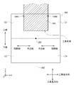
- FIG. 14 is a schematic view showing a partial image at the time of detecting the tip of the tool in the modified example 1.
- the position specifying portion 154 identifies the tip portion (hereinafter referred to as “tool tip”) of the tool 102.
- the center of the partial image 290 is the reference point 250.
- the lower side of the paper surface (the positive direction side of the Y axis) is referred to as the "lower side”
- the upper side of the paper surface (the negative side of the Y axis) is referred to as the "upper side”.
- the direction in which the tool 102 extends is called the "tool long direction”, and the radial direction (short direction) of the tool 102 is called the “tool radial direction”.
- the line in the Y-axis direction that passes through the reference point 250 is called the "center line 292".
- the direction approaching the center line 292 in the tool radial direction is referred to as “center side”
- the direction away from the center line 292 is referred to as "end side”.
- the upper right area is the first area C1
- the upper left area is the second area C2
- the lower left area is the third area C3
- the lower right area is the fourth area. It is called region C4.
- the position specifying unit 154 identifies a plurality of second edge points 194 by the same method as that described in connection with FIGS. 11 and 12.
- the position specifying portion 154 selects the second edge point 194 farthest from the reference point 250.
- the second edge point 194 farthest from the reference point 250 is the second edge point 194B and the second edge point 194C.
- the position specifying unit 154 selects the second edge point 194 on the first region C1 or the center line 292 from the second edge point 194B and the second edge point 194C.
- the second edge point 194B in the first region C1 is selected.
- the position control unit 156 instructs the machining control unit 122 to move the tool 102 so that the selected second edge point 194B (selected second edge point) and the reference point 250 overlap.
- FIG. 15 is a schematic view showing a partial image after the tool is moved in the modified example 1.
- the position control unit 156 again selects the second edge point 194E farthest from the reference point 250.
- the second edge point 194E does not satisfy the condition of "on the first region C1 or the center line 292".
- the position control unit 156 selects the second edge point 194D, which is the distant next to the second edge point 194E. Since the second edge point 194D is on the center line 292, the above condition is satisfied.
- the position control unit 156 instructs the machining control unit 122 in the moving direction so that the second edge point 194D (selected second edge point) and the reference point 250 overlap.
- a plurality of partial images 290 are acquired from the tool 102 by repeating such control.
- FIG. 16 is a first schematic diagram showing a position control method when a second edge point is detected in the third region in the second modification.
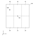
- the partial image 290 is divided into six regions from the first region D1 to the sixth region D6 as shown in FIG.
- the second edge point 194F (the second edge point 194 farthest from the reference point 250) is detected in the third region D3 on the upper left.
- FIG. 17 is a second schematic diagram showing a position control method when a second edge point is detected in the third region in the second modification.
- the position control unit 156 instructs the machining control unit 122 in the moving direction of the tool 102 so that the second edge point 194F is included in the fifth region D5.
- the tool 102 moves in both the Y direction (tool length direction) and the X direction (tool radial direction).
- FIG. 18 is a first schematic diagram showing a position control method when a second edge point is detected in the sixth region in the second modification.
- the second edge point 194G (the second edge point 194 farthest from the reference point 250) is detected in the sixth region D6 at the lower left.
- FIG. 19 is a second schematic diagram showing a position control method when a second edge point is detected in the sixth region in the second modification. Similar to FIGS. 16 and 17, the position control unit 156 instructs the machining control unit 122 the moving direction of the tool 102 so that the second edge point 194G is included in the fifth region D5. As shown in FIG. 19, when the second edge point 194G is detected in the sixth region D6, the tool 102 moves in the X direction (tool radial direction).
- the position specifying unit 154 detects a plurality of second edge points 194, and sets the second edge points 194 in the upper half (first region D1 to third region D3) of the partial image 290 (imaging region 170). select. Although it has been described in FIGS. 17 to 19 that the second edge point 194 farthest from the reference point 250 is selected, it may be any second edge point 194 in the upper half.
- the position control unit 156 instructs the machining control unit 122 to move the tool 102 so that the selected second edge point 194 is located in the middle region (fifth region D4) in which the lower half is divided into three. ..
Landscapes
- Engineering & Computer Science (AREA)
- Physics & Mathematics (AREA)
- Computer Vision & Pattern Recognition (AREA)
- Theoretical Computer Science (AREA)
- General Physics & Mathematics (AREA)
- Optics & Photonics (AREA)
- Mechanical Engineering (AREA)
- Signal Processing (AREA)
- Multimedia (AREA)
- Quality & Reliability (AREA)
- Radar, Positioning & Navigation (AREA)
- Remote Sensing (AREA)
- Electromagnetism (AREA)
- Image Analysis (AREA)
- Machine Tool Sensing Apparatuses (AREA)
Priority Applications (4)
| Application Number | Priority Date | Filing Date | Title |
|---|---|---|---|
| JP2022561961A JPWO2022102656A1 (https=) | 2020-11-11 | 2021-11-10 | |
| CN202180039423.2A CN115697628B (zh) | 2020-11-11 | 2021-11-10 | 图像处理装置以及机床 |
| EP21891902.5A EP4144479A4 (en) | 2020-11-11 | 2021-11-10 | IMAGE PROCESSING DEVICE AND MACHINE TOOL |
| US18/070,898 US12423843B2 (en) | 2020-11-11 | 2022-11-29 | Image processing device and machine tool |
Applications Claiming Priority (2)
| Application Number | Priority Date | Filing Date | Title |
|---|---|---|---|
| JP2020187758 | 2020-11-11 | ||
| JP2020-187758 | 2020-11-11 |
Related Child Applications (1)
| Application Number | Title | Priority Date | Filing Date |
|---|---|---|---|
| US18/070,898 Continuation US12423843B2 (en) | 2020-11-11 | 2022-11-29 | Image processing device and machine tool |
Publications (1)
| Publication Number | Publication Date |
|---|---|
| WO2022102656A1 true WO2022102656A1 (ja) | 2022-05-19 |
Family
ID=81602283
Family Applications (1)
| Application Number | Title | Priority Date | Filing Date |
|---|---|---|---|
| PCT/JP2021/041336 Ceased WO2022102656A1 (ja) | 2020-11-11 | 2021-11-10 | 画像処理装置および工作機械 |
Country Status (4)
| Country | Link |
|---|---|
| US (1) | US12423843B2 (https=) |
| EP (1) | EP4144479A4 (https=) |
| JP (1) | JPWO2022102656A1 (https=) |
| WO (1) | WO2022102656A1 (https=) |
Cited By (1)
| Publication number | Priority date | Publication date | Assignee | Title |
|---|---|---|---|---|
| WO2025120846A1 (ja) * | 2023-12-08 | 2025-06-12 | 株式会社Saias | 工具撮像装置 |
Families Citing this family (1)
| Publication number | Priority date | Publication date | Assignee | Title |
|---|---|---|---|---|
| NO20240673A1 (en) * | 2024-06-21 | 2025-12-22 | Conoptica As | Determining radial withdrawal and cutter edge geometry of a cutter on a rotating tool |
Citations (4)
| Publication number | Priority date | Publication date | Assignee | Title |
|---|---|---|---|---|
| JPH0347738U (https=) * | 1989-09-14 | 1991-05-07 | ||
| US20010017699A1 (en) * | 2000-01-08 | 2001-08-30 | Joachim Egelhof | Method and measuring device for measuring a rotary tool |
| JP2012091288A (ja) * | 2010-10-27 | 2012-05-17 | Makino Milling Mach Co Ltd | 工具寸法の測定方法及び測定装置 |
| JP2020032475A (ja) * | 2018-08-28 | 2020-03-05 | ファナック株式会社 | 工具識別装置及び工具識別システム |
Family Cites Families (7)
| Publication number | Priority date | Publication date | Assignee | Title |
|---|---|---|---|---|
| JP2921660B2 (ja) * | 1995-10-07 | 1999-07-19 | 川崎重工業株式会社 | 物品形状計測方法および装置 |
| JP3608920B2 (ja) * | 1997-10-14 | 2005-01-12 | 株式会社ミツトヨ | 非接触画像計測システム |
| US9453716B2 (en) | 2010-10-22 | 2016-09-27 | Makino Milling Machine Co., Ltd. | Method of measurement and apparatus for measurement of tool dimensions |
| JP5725796B2 (ja) * | 2010-10-27 | 2015-05-27 | 株式会社牧野フライス製作所 | 工具の測定方法及び測定装置、並びに工作機械 |
| JP2016218550A (ja) | 2015-05-15 | 2016-12-22 | ファナック株式会社 | 加工に使用する工具の取付け状態を確認する数値制御装置 |
| JP7014918B1 (ja) * | 2021-02-01 | 2022-02-01 | Dmg森精機株式会社 | 工作機械 |
| EP4249169A4 (en) * | 2021-09-29 | 2024-12-04 | DMG Mori Co., Ltd. | INFORMATION PROCESSING DEVICE, PROCESSING SYSTEM, PROCESSING TOOL AND PROGRAM |
-
2021
- 2021-11-10 WO PCT/JP2021/041336 patent/WO2022102656A1/ja not_active Ceased
- 2021-11-10 EP EP21891902.5A patent/EP4144479A4/en active Pending
- 2021-11-10 JP JP2022561961A patent/JPWO2022102656A1/ja active Pending
-
2022
- 2022-11-29 US US18/070,898 patent/US12423843B2/en active Active
Patent Citations (4)
| Publication number | Priority date | Publication date | Assignee | Title |
|---|---|---|---|---|
| JPH0347738U (https=) * | 1989-09-14 | 1991-05-07 | ||
| US20010017699A1 (en) * | 2000-01-08 | 2001-08-30 | Joachim Egelhof | Method and measuring device for measuring a rotary tool |
| JP2012091288A (ja) * | 2010-10-27 | 2012-05-17 | Makino Milling Mach Co Ltd | 工具寸法の測定方法及び測定装置 |
| JP2020032475A (ja) * | 2018-08-28 | 2020-03-05 | ファナック株式会社 | 工具識別装置及び工具識別システム |
Non-Patent Citations (1)
| Title |
|---|
| See also references of EP4144479A4 * |
Cited By (2)
| Publication number | Priority date | Publication date | Assignee | Title |
|---|---|---|---|---|
| WO2025120846A1 (ja) * | 2023-12-08 | 2025-06-12 | 株式会社Saias | 工具撮像装置 |
| JP7716814B1 (ja) * | 2023-12-08 | 2025-08-01 | 株式会社Saias | 工具撮像装置 |
Also Published As
| Publication number | Publication date |
|---|---|
| JPWO2022102656A1 (https=) | 2022-05-19 |
| EP4144479A4 (en) | 2024-05-29 |
| CN115697628A (zh) | 2023-02-03 |
| EP4144479A1 (en) | 2023-03-08 |
| US20230089383A1 (en) | 2023-03-23 |
| US12423843B2 (en) | 2025-09-23 |
Similar Documents
| Publication | Publication Date | Title |
|---|---|---|
| EP2082850B1 (en) | Generating device of processing robot program | |
| JP6399832B2 (ja) | パターンマッチング方法及びパターンマッチング装置 | |
| JP5923824B2 (ja) | 画像処理装置 | |
| US11625842B2 (en) | Image processing apparatus and image processing method | |
| CN103722449B (zh) | 工具机加工定位方法及其装置 | |
| US12423843B2 (en) | Image processing device and machine tool | |
| JP2001319219A (ja) | 画像測定装置用パートプログラム生成装置及び方法、並びに画像測定装置及びその測定結果表示方法 | |
| JP6588704B2 (ja) | 工具刃先の検出方法及び装置並びに工具補正値の設定装置 | |
| JP2014060324A (ja) | 算出装置、搬送ロボットシステム、及び算出方法 | |
| JP6946587B1 (ja) | 画像処理装置および工作機械 | |
| EP4032653B1 (en) | Sheet metal working system, a sheet metal working method, and machining region setting program for laser machining | |
| US20230386066A1 (en) | Image processing device and machine tool | |
| CN116867619B (zh) | 示教装置 | |
| CN115697628B (zh) | 图像处理装置以及机床 | |
| US20250116503A1 (en) | Image measuring apparatus and program | |
| JP6486632B2 (ja) | 工具の形状取得方法及び装置 | |
| US20150287177A1 (en) | Image measuring device | |
| JP2003202208A (ja) | 画像測定装置及び画像測定用プログラム | |
| JP3900319B2 (ja) | 画像計測装置及びその画像表示方法 | |
| US20170115653A1 (en) | System and Method for Performing Operations of Numerical Control Machines | |
| JP7061701B1 (ja) | 画像処理装置および工作機械 | |
| EP4272895A1 (en) | Image processing device | |
| JPH11351824A (ja) | 座標系補正方法及び画像測定装置 | |
| JP7262651B2 (ja) | 情報処理装置、工作システムおよびプログラム | |
| JP7630735B1 (ja) | 形状モデル作成作業の支援装置、形状モデル作成作業の支援方法、形状モデル作成作業の支援プログラム、及び加工システム |
Legal Events
| Date | Code | Title | Description |
|---|---|---|---|
| 121 | Ep: the epo has been informed by wipo that ep was designated in this application |
Ref document number: 21891902 Country of ref document: EP Kind code of ref document: A1 |
|
| ENP | Entry into the national phase |
Ref document number: 2021891902 Country of ref document: EP Effective date: 20221129 |
|
| ENP | Entry into the national phase |
Ref document number: 2022561961 Country of ref document: JP Kind code of ref document: A |
|
| NENP | Non-entry into the national phase |
Ref country code: DE |