WO2022102466A1 - 液晶表示素子、表示装置および電子機器、並びに、駆動基板および駆動基板の製造方法 - Google Patents
液晶表示素子、表示装置および電子機器、並びに、駆動基板および駆動基板の製造方法 Download PDFInfo
- Publication number
- WO2022102466A1 WO2022102466A1 PCT/JP2021/040327 JP2021040327W WO2022102466A1 WO 2022102466 A1 WO2022102466 A1 WO 2022102466A1 JP 2021040327 W JP2021040327 W JP 2021040327W WO 2022102466 A1 WO2022102466 A1 WO 2022102466A1
- Authority
- WO
- WIPO (PCT)
- Prior art keywords
- dielectric film
- liquid crystal
- crystal display
- display element
- drive substrate
- Prior art date
- Legal status (The legal status is an assumption and is not a legal conclusion. Google has not performed a legal analysis and makes no representation as to the accuracy of the status listed.)
- Ceased
Links
Images















Classifications
-
- G—PHYSICS
- G02—OPTICS
- G02F—OPTICAL DEVICES OR ARRANGEMENTS FOR THE CONTROL OF LIGHT BY MODIFICATION OF THE OPTICAL PROPERTIES OF THE MEDIA OF THE ELEMENTS INVOLVED THEREIN; NON-LINEAR OPTICS; FREQUENCY-CHANGING OF LIGHT; OPTICAL LOGIC ELEMENTS; OPTICAL ANALOGUE/DIGITAL CONVERTERS
- G02F1/00—Devices or arrangements for the control of the intensity, colour, phase, polarisation or direction of light arriving from an independent light source, e.g. switching, gating or modulating; Non-linear optics
- G02F1/01—Devices or arrangements for the control of the intensity, colour, phase, polarisation or direction of light arriving from an independent light source, e.g. switching, gating or modulating; Non-linear optics for the control of the intensity, phase, polarisation or colour
- G02F1/13—Devices or arrangements for the control of the intensity, colour, phase, polarisation or direction of light arriving from an independent light source, e.g. switching, gating or modulating; Non-linear optics for the control of the intensity, phase, polarisation or colour based on liquid crystals, e.g. single liquid crystal display cells
- G02F1/133—Constructional arrangements; Operation of liquid crystal cells; Circuit arrangements
- G02F1/1333—Constructional arrangements; Manufacturing methods
- G02F1/1335—Structural association of cells with optical devices, e.g. polarisers or reflectors
- G02F1/133553—Reflecting elements
-
- G—PHYSICS
- G02—OPTICS
- G02F—OPTICAL DEVICES OR ARRANGEMENTS FOR THE CONTROL OF LIGHT BY MODIFICATION OF THE OPTICAL PROPERTIES OF THE MEDIA OF THE ELEMENTS INVOLVED THEREIN; NON-LINEAR OPTICS; FREQUENCY-CHANGING OF LIGHT; OPTICAL LOGIC ELEMENTS; OPTICAL ANALOGUE/DIGITAL CONVERTERS
- G02F1/00—Devices or arrangements for the control of the intensity, colour, phase, polarisation or direction of light arriving from an independent light source, e.g. switching, gating or modulating; Non-linear optics
- G02F1/01—Devices or arrangements for the control of the intensity, colour, phase, polarisation or direction of light arriving from an independent light source, e.g. switching, gating or modulating; Non-linear optics for the control of the intensity, phase, polarisation or colour
- G02F1/13—Devices or arrangements for the control of the intensity, colour, phase, polarisation or direction of light arriving from an independent light source, e.g. switching, gating or modulating; Non-linear optics for the control of the intensity, phase, polarisation or colour based on liquid crystals, e.g. single liquid crystal display cells
- G02F1/133—Constructional arrangements; Operation of liquid crystal cells; Circuit arrangements
- G02F1/1333—Constructional arrangements; Manufacturing methods
- G02F1/1335—Structural association of cells with optical devices, e.g. polarisers or reflectors
- G02F1/133504—Diffusing, scattering, diffracting elements
- G02F1/133507—Films for enhancing the luminance
-
- G—PHYSICS
- G03—PHOTOGRAPHY; CINEMATOGRAPHY; ANALOGOUS TECHNIQUES USING WAVES OTHER THAN OPTICAL WAVES; ELECTROGRAPHY; HOLOGRAPHY
- G03B—APPARATUS OR ARRANGEMENTS FOR TAKING PHOTOGRAPHS OR FOR PROJECTING OR VIEWING THEM; APPARATUS OR ARRANGEMENTS EMPLOYING ANALOGOUS TECHNIQUES USING WAVES OTHER THAN OPTICAL WAVES; ACCESSORIES THEREFOR
- G03B21/00—Projectors or projection-type viewers; Accessories therefor
-
- G—PHYSICS
- G09—EDUCATION; CRYPTOGRAPHY; DISPLAY; ADVERTISING; SEALS
- G09F—DISPLAYING; ADVERTISING; SIGNS; LABELS OR NAME-PLATES; SEALS
- G09F9/00—Indicating arrangements for variable information in which the information is built-up on a support by selection or combination of individual elements
-
- G—PHYSICS
- G09—EDUCATION; CRYPTOGRAPHY; DISPLAY; ADVERTISING; SEALS
- G09F—DISPLAYING; ADVERTISING; SIGNS; LABELS OR NAME-PLATES; SEALS
- G09F9/00—Indicating arrangements for variable information in which the information is built-up on a support by selection or combination of individual elements
- G09F9/30—Indicating arrangements for variable information in which the information is built-up on a support by selection or combination of individual elements in which the desired character or characters are formed by combining individual elements
-
- G—PHYSICS
- G02—OPTICS
- G02F—OPTICAL DEVICES OR ARRANGEMENTS FOR THE CONTROL OF LIGHT BY MODIFICATION OF THE OPTICAL PROPERTIES OF THE MEDIA OF THE ELEMENTS INVOLVED THEREIN; NON-LINEAR OPTICS; FREQUENCY-CHANGING OF LIGHT; OPTICAL LOGIC ELEMENTS; OPTICAL ANALOGUE/DIGITAL CONVERTERS
- G02F1/00—Devices or arrangements for the control of the intensity, colour, phase, polarisation or direction of light arriving from an independent light source, e.g. switching, gating or modulating; Non-linear optics
- G02F1/01—Devices or arrangements for the control of the intensity, colour, phase, polarisation or direction of light arriving from an independent light source, e.g. switching, gating or modulating; Non-linear optics for the control of the intensity, phase, polarisation or colour
- G02F1/13—Devices or arrangements for the control of the intensity, colour, phase, polarisation or direction of light arriving from an independent light source, e.g. switching, gating or modulating; Non-linear optics for the control of the intensity, phase, polarisation or colour based on liquid crystals, e.g. single liquid crystal display cells
- G02F1/133—Constructional arrangements; Operation of liquid crystal cells; Circuit arrangements
- G02F1/1333—Constructional arrangements; Manufacturing methods
- G02F1/1335—Structural association of cells with optical devices, e.g. polarisers or reflectors
- G02F1/1336—Illuminating devices
- G02F1/133616—Front illuminating devices
-
- G—PHYSICS
- G02—OPTICS
- G02F—OPTICAL DEVICES OR ARRANGEMENTS FOR THE CONTROL OF LIGHT BY MODIFICATION OF THE OPTICAL PROPERTIES OF THE MEDIA OF THE ELEMENTS INVOLVED THEREIN; NON-LINEAR OPTICS; FREQUENCY-CHANGING OF LIGHT; OPTICAL LOGIC ELEMENTS; OPTICAL ANALOGUE/DIGITAL CONVERTERS
- G02F1/00—Devices or arrangements for the control of the intensity, colour, phase, polarisation or direction of light arriving from an independent light source, e.g. switching, gating or modulating; Non-linear optics
- G02F1/01—Devices or arrangements for the control of the intensity, colour, phase, polarisation or direction of light arriving from an independent light source, e.g. switching, gating or modulating; Non-linear optics for the control of the intensity, phase, polarisation or colour
- G02F1/13—Devices or arrangements for the control of the intensity, colour, phase, polarisation or direction of light arriving from an independent light source, e.g. switching, gating or modulating; Non-linear optics for the control of the intensity, phase, polarisation or colour based on liquid crystals, e.g. single liquid crystal display cells
- G02F1/133—Constructional arrangements; Operation of liquid crystal cells; Circuit arrangements
- G02F1/136—Liquid crystal cells structurally associated with a semi-conducting layer or substrate, e.g. cells forming part of an integrated circuit
- G02F1/1362—Active matrix addressed cells
- G02F1/136277—Active matrix addressed cells formed on a semiconductor substrate, e.g. of silicon
-
- G—PHYSICS
- G02—OPTICS
- G02F—OPTICAL DEVICES OR ARRANGEMENTS FOR THE CONTROL OF LIGHT BY MODIFICATION OF THE OPTICAL PROPERTIES OF THE MEDIA OF THE ELEMENTS INVOLVED THEREIN; NON-LINEAR OPTICS; FREQUENCY-CHANGING OF LIGHT; OPTICAL LOGIC ELEMENTS; OPTICAL ANALOGUE/DIGITAL CONVERTERS
- G02F1/00—Devices or arrangements for the control of the intensity, colour, phase, polarisation or direction of light arriving from an independent light source, e.g. switching, gating or modulating; Non-linear optics
- G02F1/01—Devices or arrangements for the control of the intensity, colour, phase, polarisation or direction of light arriving from an independent light source, e.g. switching, gating or modulating; Non-linear optics for the control of the intensity, phase, polarisation or colour
- G02F1/13—Devices or arrangements for the control of the intensity, colour, phase, polarisation or direction of light arriving from an independent light source, e.g. switching, gating or modulating; Non-linear optics for the control of the intensity, phase, polarisation or colour based on liquid crystals, e.g. single liquid crystal display cells
- G02F1/133—Constructional arrangements; Operation of liquid crystal cells; Circuit arrangements
- G02F1/136—Liquid crystal cells structurally associated with a semi-conducting layer or substrate, e.g. cells forming part of an integrated circuit
- G02F1/1362—Active matrix addressed cells
- G02F1/136286—Wiring, e.g. gate line, drain line
- G02F1/13629—Multilayer wirings
-
- G—PHYSICS
- G02—OPTICS
- G02F—OPTICAL DEVICES OR ARRANGEMENTS FOR THE CONTROL OF LIGHT BY MODIFICATION OF THE OPTICAL PROPERTIES OF THE MEDIA OF THE ELEMENTS INVOLVED THEREIN; NON-LINEAR OPTICS; FREQUENCY-CHANGING OF LIGHT; OPTICAL LOGIC ELEMENTS; OPTICAL ANALOGUE/DIGITAL CONVERTERS
- G02F2201/00—Constructional arrangements not provided for in groups G02F1/00 - G02F7/00
- G02F2201/12—Constructional arrangements not provided for in groups G02F1/00 - G02F7/00 electrode
- G02F2201/123—Constructional arrangements not provided for in groups G02F1/00 - G02F7/00 electrode pixel
-
- G—PHYSICS
- G02—OPTICS
- G02F—OPTICAL DEVICES OR ARRANGEMENTS FOR THE CONTROL OF LIGHT BY MODIFICATION OF THE OPTICAL PROPERTIES OF THE MEDIA OF THE ELEMENTS INVOLVED THEREIN; NON-LINEAR OPTICS; FREQUENCY-CHANGING OF LIGHT; OPTICAL LOGIC ELEMENTS; OPTICAL ANALOGUE/DIGITAL CONVERTERS
- G02F2203/00—Function characteristic
- G02F2203/02—Function characteristic reflective
Definitions
- the present disclosure relates to a liquid crystal display element, a display device and an electronic device, and a drive board and a method for manufacturing the drive board.
- liquid crystal display element in which pixels including liquid crystal cells are two-dimensionally arranged in a matrix, an image is displayed by operating the pixels as an optical shutter (light valve).
- a direct-view type display device and a projection type (projector type) display device have been put into practical use.
- projection type display devices have expanded their applications such as for large-scale conference rooms and entertainment, and there is a demand for higher definition and higher image quality, so-called active matrix type.
- Liquid crystal display elements are widely used.
- Reflective liquid crystal display elements such as LCOS (Liquid Crystal On Silicon) and HTPS (High Temperature Poly-Silicon) turn on or off the reflection of light by using the polarization of the liquid crystal for the light incident on the liquid crystal display element.
- the image is displayed by controlling the state of (see, for example, Patent Document 1).
- the reflective liquid crystal display element includes light-reflecting pixel electrodes such as a pixel electrode made of a material that reflects light and a pixel electrode on which a light-reflecting film is laminated.
- the circuit wiring and the like are arranged under the light-reflecting pixel electrode. Therefore, the reflective liquid crystal display element has an advantage that the aperture ratio can be increased as compared with the transmissive liquid crystal display element.
- Pixel voltage is applied independently to each of the light-reflecting pixel electrodes. Therefore, the pixel electrodes are arranged apart from the adjacent pixel electrodes, and basically, the light incident on the separated portion does not participate in the image display. In order to increase the brightness of the displayed image, it is preferable to reduce the area occupied between the pixel electrodes.
- the higher the definition of the liquid crystal display element the smaller the size of the pixel electrode.
- due to restrictions such as patterning there is no choice but to leave a certain distance between the pixel electrodes.
- the definition becomes higher the ratio of the area occupied between the pixel electrodes increases, and the utilization efficiency of the light incident on the liquid crystal display element decreases.
- an object of the present disclosure is a liquid crystal display element capable of reducing a decrease in light utilization efficiency caused by high definition, a display device and an electronic device provided with the liquid crystal display element, and the liquid crystal display element. It is an object of the present invention to provide a drive board used for the above and a method for manufacturing the drive board.
- the liquid crystal display element according to the present disclosure for achieving the above object is a drive substrate having light-reflecting pixel electrodes arranged in a matrix, an opposed substrate arranged to face the drive substrate, and a drive substrate.
- a liquid crystal material layer sandwiched between the The entire surface including the upper surface is covered with the first dielectric film formed on the pixel electrode and the second dielectric film formed in the slit portion, and the second dielectric film is formed along the slit portion.
- a liquid crystal display element having an extending hollow portion.
- the display device for achieving the above object includes a liquid crystal display element and a light source unit that irradiates the liquid crystal display element with light, and the liquid crystal display element includes light arranged in a matrix.
- Each pixel electrode includes a drive substrate having a reflective pixel electrode, a facing substrate arranged to face the drive substrate, and a liquid crystal material layer sandwiched between the drive substrate and the facing substrate. They are arranged on the display surface side of the drive substrate in a state of being separated from each other via the slit portion, and the entire surface including the pixel electrode is formed on the first dielectric film formed on the pixel electrode and the slit portion.
- the second dielectric film is covered with the formed second dielectric film, and the second dielectric film is a display device having a hollow portion extending along the slit portion.
- the electronic device for achieving the above object includes a liquid crystal display element and a light source unit that irradiates the liquid crystal display element with light, and the liquid crystal display element includes light arranged in a matrix.
- Each pixel electrode includes a drive substrate having a reflective pixel electrode, a facing substrate arranged to face the drive substrate, and a liquid crystal material layer sandwiched between the drive substrate and the facing substrate. They are arranged on the display surface side of the drive substrate in a state of being separated from each other via the slit portion, and the entire surface including the pixel electrode is formed on the first dielectric film formed on the pixel electrode and the slit portion.
- the second dielectric film is covered with a second dielectric film, and the second dielectric film is an electronic device including a display device having a hollow portion extending along a slit portion.
- the drive substrate according to the present disclosure for achieving the above object is a drive substrate having light-reflecting pixel electrodes arranged in a matrix, and the pixel electrodes are separated from each other via a slit portion. It is arranged on the display surface side of the drive substrate, and the entire surface including the pixel electrode is covered with the first dielectric film formed on the pixel electrode and the second dielectric film formed on the slit portion.
- the second dielectric film is a drive substrate having a hollow portion extending along the slit portion.
- the method for manufacturing a drive substrate according to the present disclosure for achieving the above object is a method for manufacturing a drive board having light-reflecting pixel electrodes arranged in a matrix, and pixels are on the display surface side of the drive board.
- It is a method for manufacturing a drive substrate which comprises a step of forming a second dielectric film formed in a slit portion by subjecting a dielectric material layer to a flattening treatment.
- FIG. 1 is a schematic diagram of a liquid crystal display element according to the first embodiment.
- FIG. 2A is a schematic cross-sectional view for explaining a basic configuration of a liquid crystal display element.
- FIG. 2B is a schematic circuit diagram for explaining pixels in a liquid crystal display element.
- FIG. 3 is a schematic partial cross-sectional view of a substrate or the like for explaining the structure of the liquid crystal display element.
- FIG. 4 is a schematic cross-sectional view of the liquid crystal display element in the portion shown by AA in FIG.
- FIG. 5 is a schematic cross-sectional view of the liquid crystal display element in the portion shown by BB in FIG.
- FIG. 6 is a schematic cross-sectional view for explaining a cross-sectional shape of a portion between adjacent pixel electrodes.
- FIG. 1 is a schematic diagram of a liquid crystal display element according to the first embodiment.
- FIG. 2A is a schematic cross-sectional view for explaining a basic configuration of a liquid crystal display element.
- FIG. 7A is a schematic cross-sectional view for explaining the cross-sectional shape of a portion between adjacent pixel electrodes in the liquid crystal display element according to the reference example.
- FIG. 7B is a schematic cross-sectional view for explaining a state of light incident on a portion between adjacent pixel electrodes.
- FIG. 8A is a schematic cross-sectional view for explaining a cross-sectional shape of a portion between adjacent pixel electrodes in the liquid crystal display element according to the first embodiment.
- FIG. 8B is a schematic cross-sectional view for explaining a state of light incident on a portion between adjacent pixel electrodes.
- 9A and 9B are schematic partial cross-sectional views of a substrate or the like for explaining a method for manufacturing a liquid crystal display element according to the first embodiment.
- FIG. 10 is a schematic partial cross-sectional view of a substrate or the like for explaining a method for manufacturing a liquid crystal display element according to the first embodiment, following FIG. 9B.
- FIG. 11 is a schematic partial cross-sectional view of a substrate or the like for explaining a method for manufacturing a liquid crystal display element according to the first embodiment, following FIG. 10.
- FIG. 12 is a schematic partial cross-sectional view of a substrate or the like for explaining a method for manufacturing a liquid crystal display element according to the first embodiment, following FIG. 11.
- FIG. 13 is a schematic partial cross-sectional view of a substrate or the like for explaining a method of manufacturing a liquid crystal display element according to the first embodiment, following FIG. 12.
- FIG. 12 is a schematic partial cross-sectional view of a substrate or the like for explaining a method of manufacturing a liquid crystal display element according to the first embodiment, following FIG. 12.
- FIG. 12 is a schematic partial cross-sectional view of a substrate or the like for explaining a method of manufacturing
- FIG. 14 is a schematic partial cross-sectional view of a substrate or the like for explaining a method for manufacturing a liquid crystal display element according to the first embodiment, following FIG. 13.
- FIG. 15 is a schematic partial cross-sectional view of a substrate or the like for explaining a method for manufacturing a liquid crystal display element according to the first embodiment, following FIG.
- FIG. 16 is a schematic partial cross-sectional view of a substrate or the like for explaining a method for manufacturing a liquid crystal display element according to the first embodiment, following FIG.
- FIG. 17 is a schematic partial cross-sectional view of a substrate or the like for explaining the structure of the liquid crystal display element according to the second embodiment.
- FIG. 18 is a schematic cross-sectional view for explaining a cross-sectional shape of a portion between adjacent pixel electrodes.
- FIG. 19A is a schematic cross-sectional view for explaining the state of light incident on the vicinity of the pixel electrode end in the liquid crystal display element according to the first embodiment.
- FIG. 19B is a schematic cross-sectional view for explaining the state of light incident on the vicinity of the pixel electrode end in the liquid crystal display element according to the second embodiment.
- FIG. 20 is a schematic partial cross-sectional view of a substrate or the like for explaining the structure of the liquid crystal display element according to the first modification of the second embodiment.
- FIG. 21 is a schematic cross-sectional view for explaining a cross-sectional shape of a portion between adjacent pixel electrodes.
- FIG. 22A is a schematic cross-sectional view for explaining the cross-sectional shape of the portion between the adjacent pixel electrodes, and shows a case where the distance between the adjacent pixel electrodes is appropriate.
- FIG. 22B is a schematic cross-sectional view for explaining the cross-sectional shape of the portion between the adjacent pixel electrodes, and shows the case where the distance between the adjacent pixel electrodes is excessive.
- FIG. 23 is a schematic plan view for explaining the distance between adjacent pixel electrodes.
- FIG. 24 is a schematic plan view for explaining the distance between adjacent pixel electrodes, following FIG. 23.
- FIG. 25 is a schematic plan view for explaining an arrangement example of the pixel electrodes in which the expansion of the diagonal distance of the pixel electrodes is suppressed.
- FIG. 22A is a schematic cross-sectional view for explaining the cross-sectional shape of the portion between the adjacent pixel electrodes, and shows a case where the distance between the adjacent pixel electrodes is appropriate.
- FIG. 22B is a schematic cross
- FIG. 26 is a schematic plan view for explaining an arrangement example in which the expansion of the diagonal distance of the pixel electrodes is suppressed by arranging the island-shaped region of the same layer as the pixel electrodes between the pixel electrodes. ..
- FIG. 27 is a conceptual diagram of a projection type display device.
- FIG. 28 is an external view of an interchangeable lens type single-lens reflex type digital still camera, the front view thereof is shown in FIG. 28A, and the rear view thereof is shown in FIG. 28B.
- FIG. 29 is an external view of the head-mounted display.
- FIG. 30 is an external view of a see-through head-mounted display.
- FIG. 31 is a block diagram showing an example of a schematic configuration of a vehicle control system.
- FIG. 32 is an explanatory diagram showing an example of the installation positions of the vehicle exterior information detection unit and the image pickup unit.
- FIG. 33 is a diagram schematically showing the overall configuration of the operating room system.
- FIG. 34 is a diagram showing a display example of an operation screen on the centralized operation panel.
- FIG. 35 is a diagram showing an example of a state of surgery to which the operating room system is applied.
- FIG. 36 is a block diagram showing an example of the functional configuration of the camera head and the CCU shown in FIG. 35.
- the liquid crystal display elements, display devices and display devices According to the following description, the liquid crystal display elements, display devices and display devices according to the present disclosure.
- the liquid crystal display element used in the above and the liquid crystal display element used in the electronic device according to the present disclosure may be simply referred to as "the liquid crystal display element of the present disclosure”.
- the drive substrate according to the present disclosure, the drive substrate obtained by the method for manufacturing the drive substrate according to the present disclosure, and the drive substrate used for the liquid crystal display element of the present disclosure are simply referred to as "the drive substrate of the present disclosure”. In some cases.
- the liquid crystal display element according to the present disclosure, the display device and the electronic device according to the present disclosure, and the drive substrate and the method for manufacturing the drive substrate according to the present disclosure may be simply referred to as "the present disclosure”.
- the liquid crystal display element of the present disclosure includes a drive substrate having light-reflecting pixel electrodes arranged in a matrix, a facing substrate arranged to face the drive substrate, and a drive substrate and a facing substrate. It contains a liquid crystal material layer sandwiched between the two.
- the pixel electrodes are arranged on the display surface side of the drive substrate in a state of being separated from each other via a slit portion, and the entire surface including the pixel electrode is formed on the pixel electrode. It is covered with the formed first dielectric film and the second dielectric film formed in the slit portion, and the second dielectric film has a hollow portion extending along the slit portion.
- the light incident on the second dielectric film the light that satisfies the total reflection condition is reflected at the interface with the hollow portion, and its direction changes.
- the light directed toward the pixel electrode side contributes to the display of the image, so that the utilization efficiency of the light incident on the liquid crystal display element is improved.
- the hollow portion may have a wall surface extending toward the drive board side.
- the first dielectric film and the second dielectric film can be configured to be made of the same material. From the viewpoint of process easiness, it is preferable that the first dielectric film and the second dielectric film are made of silicon oxide.
- the second dielectric film can be made of a material having a higher refractive index than the material constituting the first dielectric film.
- the first dielectric film is composed of silicon oxide
- the second dielectric film is composed of any of the group consisting of silicon nitride, tantalum oxide, titanium oxide and niobium oxide. It can be configured to consist of. From the viewpoint of process easiness, it is preferable that the second dielectric film is made of silicon nitride.
- the first dielectric film includes a lower layer portion on the pixel electrode side and an upper layer portion laminated on the lower layer portion, and the upper layer portion is a lower layer portion. It can be made of a material having a higher refractive index than the material constituting the above. From the viewpoint of process easiness, it is preferable that the lower layer portion is composed of silicon oxide and the upper layer portion is composed of silicon nitride.
- the light incident on the second dielectric film near the slit portion is directed toward the pixel electrode side due to the influence of the upper layer portion of the first dielectric film.
- light that is incident on the second dielectric film but not on the hollow portion also contributes to the display of the image. Therefore, the utilization efficiency of the light incident on the liquid crystal display element is further improved.
- the first dielectric film and the second dielectric film may be covered with a cap layer.
- the cap layer By providing the cap layer, the upper part of the formed void is filled, so that the effect of improving reliability can be obtained.
- the cap layer is preferably composed of silicon nitride or tantalum oxide.
- the method for manufacturing a drive board according to the present disclosure for manufacturing a drive board including various preferable configurations described above includes a step of forming a conductive material layer for forming a pixel electrode on the display surface side of the drive board, and a dielectric.
- the dielectric film, the conductive material layer, the dielectric material layer and the like may be, for example, a physical vapor deposition method (PVD method) exemplified by a vacuum vapor deposition method or a sputtering method, various chemical vapor deposition methods (CVD method), or the like. It can be formed by a combination of a well-known film forming method and a well-known patterning method such as an etching method or a lift-off method. Further, the flattening treatment applied to the dielectric material layer can be performed by a method such as a chemical / mechanical polishing method (CMP method).
- CMP method chemical / mechanical polishing method
- a substrate made of a transparent material such as glass or a substrate made of a semiconductor material such as silicon can be used as the support substrate constituting the drive substrate.
- the transistor that supplies voltage to the pixel electrodes can be configured by forming and processing a semiconductor material layer or the like on the glass substrate.
- a substrate made of a semiconductor material such as silicon it can be configured, for example, by appropriately forming a transistor or the like in a well provided on the substrate.
- the configuration of the transistor used for switching is not particularly limited. It may be a p-channel type field-effect transistor or an n-channel type field-effect transistor.
- Wiring layers including various wirings and electrodes are formed on the drive board, and these can be configured by laminating a plurality of material layers on the entire surface of the support board including transistors and the like.
- the wiring and electrodes included in the wiring layer are separated by an insulating layer.
- the via for electrically connecting the wiring layer and each pixel electrode is, for example, after providing an opening in the insulating layer on the surface of the wiring layer, forming a film of tungsten (W) or the like on the entire surface, and then flattening the via. Can be formed by applying.
- the metal material layer and the insulating layer constituting the wiring layer can be formed by using a material appropriately selected from known inorganic materials and organic materials, and for example, a physical vapor phase exemplified by a vacuum vapor deposition method or a sputtering method. It can be formed by a combination of a well-known film forming method such as a growth method (PVD method) and various chemical vapor deposition methods (CVD method) and a well-known patterning method such as an etching method and a lift-off method.
- the insulating layer constituting the wiring layer can be obtained by the above-mentioned well-known film forming method.
- the light-reflecting pixel electrode can be formed by using aluminum (Al), an aluminum alloy such as Al—Cu or Al—Si, or a metal material such as silver (Ag).
- the pixel electrode can be obtained, for example, by forming a metal material on the entire surface of the wiring layer on which the via is formed by a well-known film forming method and then applying a well-known patterning method.
- a light-reflecting pixel electrode can be configured by combining an electrode made of a transparent conductive material and a reflective layer.
- a substrate made of a transparent material such as glass can be used as the facing substrate arranged to face the driving substrate.
- the counter electrode provided on the facing substrate can be formed by using a transparent conductive material such as indium tin oxide (ITO) or indium zinc oxide (IZO).
- ITO indium tin oxide
- IZO indium zinc oxide
- the counter electrode functions as a common electrode for each pixel of the liquid crystal display element.
- an alignment film made by rubbing a film made of an organic material or an alignment film made of an inorganic material can be used.
- an alignment film made of an inorganic material having excellent light resistance can be used.
- the alignment film made of an inorganic material can be formed by depositing an inorganic material such as silicon oxide from an oblique direction with respect to the substrate.
- the operation mode of the liquid crystal display element is not particularly limited. It may be configured to be driven in the so-called TN mode, or may be configured to be driven in the VA mode or the IPS mode. Further, the liquid crystal display element may be normally black or normally white. Further, the liquid crystal display element may be configured to display a monochrome image or may be configured to display a color image. For example, a liquid crystal display element for color display can be obtained by providing a color filter coated with an overcoat layer made of an acrylic resin or an epoxy resin on the inner surface of the substrate.
- the values of the pixels of the liquid crystal display element are VGA (640,480), S-VGA (800,600), XGA (1024,768), APRC (1152,900), S-XGA (1280,1024). , U-XGA (1600,1200), HD-TV (1920,1080), Q-XGA (2048,1536), (1920,1035), (720,480), (1280,960), etc. Some display resolutions can be exemplified, but are not limited to these values.
- a display device provided with the liquid crystal display element of the present disclosure a direct-view type or a projection type display device can be exemplified.
- the light source unit used in the display device include various lamps such as xenon lamps and semiconductor light emitting elements such as light emitting diodes.
- the electronic device provided with the liquid crystal display element of the present disclosure various electronic devices having an image display function can be exemplified.
- FIG. 3 which will be described later, shows the cross-sectional structure of the liquid crystal display element, but does not show the ratios such as width, height, and thickness.
- the first embodiment relates to a liquid crystal display element, a display device and an electronic device, and a drive board and a method for manufacturing the drive board according to the present disclosure.
- FIG. 1 is a schematic diagram of a liquid crystal display element according to the first embodiment.
- the liquid crystal display element 1 is an active matrix type liquid crystal display element.
- the liquid crystal display element 1 includes various circuits such as pixels PX arranged in a matrix, a horizontal drive circuit 11 for driving the pixels PX, and a vertical drive circuit 12.
- the reference numeral SCL is a scanning line for scanning the pixel PX
- the reference numeral DTL is a signal line for supplying various voltages to the pixel PX.
- the third pixel PX may be called.
- Each element constituting the (n, m) th pixel PX may also be described as the (n, m) th element.
- the liquid crystal display element 1 is a liquid crystal display element in which various circuits such as a horizontal drive circuit 11 and a vertical drive circuit 12 are integrated.
- various circuits such as a horizontal drive circuit 11 and a vertical drive circuit 12 are integrated.
- the horizontal drive circuit 11 and the vertical drive circuit 12 are respectively arranged on one end side of the liquid crystal display element 1, but this is merely an example.
- FIG. 2A is a schematic cross-sectional view for explaining the basic configuration of the liquid crystal display element.
- FIG. 2B is a schematic circuit diagram for explaining pixels in a liquid crystal display element.
- the liquid crystal display element 1 is a liquid crystal material layer sandwiched between a drive substrate 100, a facing substrate 150 arranged to face the drive substrate 100, and the drive substrate 100 and the facing substrate 150. Includes 140 and.
- the drive board 100 and the facing board 150 are sealed by a seal portion 160.
- the seal portion 160 is an annular shape surrounding the liquid crystal material layer 140.
- the drive substrate 100 includes light-reflecting pixel electrodes arranged in a matrix, a wiring layer including various electrodes and wiring, and a transistor as a switching element for supplying voltage to the pixel electrodes.
- the facing substrate 150 is composed of, for example, a rectangular substrate made of transparent glass, a counter electrode provided on the surface of the substrate on the liquid crystal material layer 140 side, an alignment film provided on the counter electrode, and the like. For convenience of illustration, the drive substrate 100 and the facing substrate 150 in FIG. 2A are shown in a simplified manner.
- the liquid crystal cell constituting the pixel PX is composed of a pixel electrode provided on the drive substrate 100, a liquid crystal material layer 140 of a portion corresponding to the pixel electrode, and a counter electrode.
- a pixel electrode provided on the drive substrate 100
- a liquid crystal material layer 140 of a portion corresponding to the pixel electrode and a counter electrode.
- positive or negative common potential Vcoms are alternately applied to the counter electrodes when the liquid crystal display element 1 is driven.
- each element excluding the liquid crystal material layer and the counter electrode is formed on the drive substrate 100 shown in FIG. 2A.
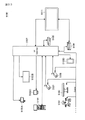
- the pixel voltage supplied from the signal line DTL is applied to the pixel electrodes via the transistor TR which is made conductive by the scanning signal of the scanning line SCL. Since the pixel electrode and one electrode of the capacitive structure CS are conducting, the pixel voltage is also applied to one electrode of the capacitive structure CS. A common potential Vcom is applied to the other electrode of the capacitive structure CS. In this configuration, the voltage of the pixel electrode is held by the capacitive component of the liquid crystal cell and the capacitive structure CS even after the transistor TR is brought into the non-conducting state.
- the pixel electrodes are arranged on the display surface side of the drive substrate in a state of being separated from each other via the slit portion.
- the entire surface including the pixel electrode is covered with the first dielectric film formed on the pixel electrode and the second dielectric film formed in the slit portion.
- the second dielectric film has a hollow portion extending along the slit portion.
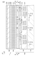
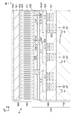
- FIG. 3 is a schematic partial cross-sectional view of a substrate or the like for explaining the structure of the liquid crystal display element.
- the liquid crystal display element 1 includes a drive substrate 100 and a facing substrate 150, and a liquid crystal material layer 140 sandwiched between the drive substrate 100 and the facing substrate 150.
- Reference numeral 141 schematically indicates a liquid crystal molecule.
- the drive board 100 includes, for example, a support board 110 made of silicon, a wiring layer 120 including various wirings, and a pixel electrode 131 formed on the wiring layer 120.
- the pixel electrode 131 is configured by laminating an Al—Cu film on a titanium film as a barrier metal, but is shown as one layer in the figure.
- a transistor 111 corresponding to the transistor TR shown in FIG. 2B is formed on the support substrate 110. Although not shown in FIG. 3, one source / drain region of the transistor 111 is connected to the data line DTL as shown in FIG. 2B.
- Each pixel electrode 131 is arranged on the display surface side (the surface on the + Z direction side in FIG. 3) of the drive substrate 100 in a state of being separated from each other via the slit portion SL.
- the entire surface including the pixel electrode 131 is covered with the first dielectric film 132 formed on the pixel electrode 131 and the second dielectric film 133 formed on the slit portion SL.
- the alignment film 135 is laminated on the entire surface including the first dielectric film 132 and the second dielectric film 133.
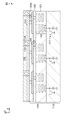
- the first dielectric film 132 and the second dielectric film 133 are made of the same material. More specifically, the first dielectric film 132 and the second dielectric film 133 are made of silicon oxide. As shown in FIG. 5, which will be described later, the second dielectric film 133 has a hollow portion 134 extending along the slit portion SL.
- reference numeral 122 indicates wiring that also serves as light shielding. These constitute the wiring on the lower layer side of the wiring layer 120.
- the wiring 122 has a mixture of those extending in the X direction and those extending in the Y direction, in FIG. 3, only the cross section extending in the X direction is schematically shown.
- Reference numeral 121 indicates an insulating layer for separating wiring from wiring to wiring. Although the insulating layer 121 is formed by laminating a plurality of interlayer insulating layers, it is shown simply for convenience of illustration.
- An interlayer insulating layer 123 is formed on the wiring 122, and a first relay electrode 125 is formed on the interlayer insulating layer 123.
- the wiring of the first relay electrode 125 and the wiring 122 is electrically connected by a via 124 provided in the interlayer insulating layer 123.
- An interlayer insulating layer 123A is formed on the entire surface including the first relay electrode 125.
- the light-reflecting pixel electrode 131 is formed on the wiring layer 120. More specifically, the pixel electrodes 131 are arranged in a matrix on the interlayer insulating layer 123A which is the surface layer of the wiring layer 120. Via 126 is formed in the interlayer insulating layer 123A. The surface of the interlayer insulating layer 123A is flattened, and the cross section of the via 126 is exposed on the surface of the interlayer insulating layer 123A. The pixel electrode 131 is formed on the surface of the wiring layer 120 that has been flattened, and is electrically connected to the wiring layer 120 via the via 126. More specifically, the pixel electrode 131 is connected to the other source / drain region of the transistor 111 via the via 126, the first relay electrode 125, the via 124 and the wiring 122.
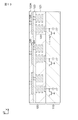
- FIG. 4 is a schematic cross-sectional view of the liquid crystal display element in the portion shown by AA in FIG.
- FIG. 5 is a schematic cross-sectional view of the liquid crystal display element in the portion shown by BB in FIG.
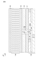
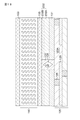
- FIG. 6 is a schematic cross-sectional view for explaining a cross-sectional shape of a portion between adjacent pixel electrodes.
- the pixel electrodes 131 are arranged on the display surface side of the drive substrate 100 in a state of being separated from each other via the slit portion SL.
- the arrangement relationship of the pixel electrode 131 is shown.
- the slit portion SL is filled with the second dielectric film 133.
- the first dielectric film 132 is arranged on the pixel electrode 131, and the second dielectric film 133 is formed in the slit portion SL.
- the hollow portion 134 is formed.
- the hollow portion 134 is formed so as to extend along the slit portion SL.
- the hollow portion 134 of the second dielectric film 133 has a wall surface WF extending toward the drive substrate 100 side. Then, at least a part of the light incident on the second dielectric film 133 is reflected by the wall surface WF of the hollow portion 134 and directed toward the pixel electrode 131 side.
- the wall surface WF of the hollow portion 134 is represented as a flat surface, but this is merely an example.
- the cross-sectional shape of the hollow portion 134 can take various shapes depending on the film forming conditions of the second dielectric film 133.
- the wall surface WF may be a curved surface having a constant curvature or a curved surface whose curvature gradually changes.
- the cross section of the hollow portion 134 is represented as a rhombus in FIG. 6, it may be a triangle having the wall surface WF as two sides.
- the function of the hollow portion 134 of the liquid crystal display element 1 will be described in comparison with the liquid crystal display element according to the reference example.
- FIG. 7A is a schematic cross-sectional view for explaining the cross-sectional shape of a portion between adjacent pixel electrodes in the liquid crystal display element according to the reference example.
- FIG. 7B is a schematic cross-sectional view for explaining a state of light incident on a portion between adjacent pixel electrodes.
- the pixel electrode 131 and the slit portion SL are all covered with the first dielectric film 132.
- the light incident on the slit portion SL passes through the slit portion SL as it is and heads toward the lower layer as shown in FIG. 7B. Therefore, these lights do not contribute to the display of the image.
- FIG. 8A is a schematic cross-sectional view for explaining a cross-sectional shape of a portion between adjacent pixel electrodes in the liquid crystal display element according to the first embodiment.
- FIG. 8B is a schematic cross-sectional view for explaining a state of light incident on a portion between adjacent pixel electrodes.
- the second dielectric film 133 is arranged on the slit portion SL, and the hollow portion 134 is formed therein.
- the hollow portion 134 has a wall surface WF that expands toward the drive substrate side. Therefore, as shown in FIG. 8B, at least a part of the light incident on the second dielectric film 133 is reflected by the wall surface WF of the hollow portion 134 and directed toward the pixel electrode 131 side. As a result, the light incident on the slit portion SL also contributes to the display of the image, so that the efficiency of light utilization can be improved.
- the wall surface WF preferably has an angle of 47 degrees or less with respect to the Z direction.
- the second dielectric film 133 is made of a material having a higher refractive index than the material constituting the first dielectric film 132.
- the first dielectric film 132 is made of silicon oxide
- the second dielectric film 133 is made of any of the group consisting of silicon nitride, tantalum oxide, titanium oxide and niobium oxide. It is conceivable that it will consist of.
- the wall surface WF is preferably at an angle of 59 degrees or less with respect to the Z direction. Further, when the second dielectric film 133 is made of tantalum oxide, the wall surface WF preferably has an angle of 63 degrees or less with respect to the Z direction.
- the facing substrate 150 arranged to face the drive substrate 100 includes, for example, a rectangular base material 151 made of quartz glass and a counter electrode 152 provided on the surface on the liquid crystal material layer 140 side. It includes an alignment film 153 provided on the counter electrode 152, and further includes a polarizing element 154 arranged on the substrate 151.
- the configuration of the splitter 154 is not particularly limited, and may be an absorption type polarizing element or a wire grid polarizing element. When heat resistance is required, it is preferable to use the splitter 154 as a wire grid splitter.
- the liquid crystal material layer 140 is sandwiched between the alignment film 135 of the drive substrate 100 and the alignment film 153 of the facing substrate 150.
- the orientation state of the liquid crystal molecules 141 when there is no electric field is defined by the alignment films 135 and 153.
- the liquid crystal display element 1 is, for example, a vertically oriented (VA) type liquid crystal display element.
- the structure of the liquid crystal display element 1 has been described in detail above.
- the relay electrode or the like described in the wiring layer 120 may have various shapes.
- the stacking relationship shown in FIG. 3 is merely an example, and the configuration may be appropriately preferable according to the configuration of the liquid crystal display element.
- the method for manufacturing the liquid crystal display element 1 includes a step of forming a conductive material layer for forming a pixel electrode 131 on the display surface side of the drive substrate 100, and a step of forming a first dielectric film 132 on the conductive material layer.
- FIGS 9 to 16 are various drawings for explaining the manufacturing method of the liquid crystal display element 1.
- the manufacturing method of the liquid crystal display element 1 will be described in detail.
- Step-100 (See FIGS. 9A, 9B and 10) A support substrate 110 on which the transistor 111 is formed is prepared (see FIG. 9A), and wiring is performed on the support substrate 110 by a well-known film forming method or patterning method.
- the lower part of the layer 120 is formed (see FIG. 9B).
- the wiring, electrodes, and the like constituting the wiring 122 can be formed of, for example, a metal material such as tungsten (W) or Al—Cu. The same applies to other wirings and electrodes described later.
- the insulating layer 121 can be formed by using, for example, a silicon oxide. The same applies to other insulating layers and the like.
- the via 124 penetrating the interlayer insulating layer 123 is formed.
- a conductive film made of a metal material is formed on the interlayer insulating layer 123, and then patterning is performed by a well-known patterning method to form the first relay electrode 125.
- the interlayer insulating layer 123A is formed on the entire surface including the first relay electrode 125, and then the via 126 penetrating the interlayer insulating layer 123A is formed. (See FIG. 10).
- the wiring layer 120 can be formed on the support substrate 110.
- Step-110 (see FIGS. 11, 12, 13, 14, and 15) Then, for forming the pixel electrode 131 on the display surface side (that is, the surface side of the wiring layer 120) of the drive substrate 100.
- a step of forming the conductive material layer 131A and a step of forming a dielectric film 132A for forming the first dielectric film 132 on the conductive material layer 131A are performed (see FIG. 11).
- the dielectric film 132A and the conductive material layer 131A are patterned to form a slit portion SL that separates the pixel electrodes 131.
- a mask 139 having an opening corresponding to the slit portion SL is formed on the dielectric film 132A (see FIG. 12), and then a dry etching process is performed to separate the dielectric film 132A and the conductive material layer 131A.
- a slit portion SL is formed (see FIG. 13). Thereby, the pixel electrode 131 and the first dielectric film 132 formed on the pixel electrode 131 can be obtained.
- a dielectric material layer 133A having a hollow portion 134 extending along the slit portion SL is formed on the entire surface including the inside of the slit portion SL by conformal film formation.
- the hollow portion 134 is formed along the slit portion SL (see FIG. 14).
- the dielectric material layer 133A can be flattened to form the second dielectric film 133 formed in the slit portion SL (see FIG. 15).
- the alignment film 135 is laminated and formed on the entire surface (see FIG. 16).
- the drive substrate 100 can be obtained by the above steps.
- Step-120 (See FIG. 3) Next, a rectangular base material 151 made of, for example, quartz glass, a counter electrode 152 provided on one surface of the base material 151, and an orientation provided on the counter electrode 152.
- the facing substrate 150 having the film 153 is prepared. Then, the drive substrate 100 and the facing substrate 150 are opposed to each other with the liquid crystal material layer 140 sandwiched therein, and the periphery is sealed. After that, the liquid crystal display element 1 can be obtained by arranging the polarizing element 154 on the other surface of the base material 151.
- the second embodiment also relates to a liquid crystal display element, a display device and an electronic device, and a drive board and a method for manufacturing the drive board according to the present disclosure.
- FIG. 17 is a schematic partial cross-sectional view of a substrate or the like for explaining the structure of the liquid crystal display element according to the second embodiment, and is a drawing corresponding to FIG. 3 referred to in the first embodiment. be.
- the liquid crystal display element 1 may be read as the liquid crystal display element 2 in FIG.
- the first dielectric film 132 was composed of a single layer of silicon oxide.
- the first dielectric film 232 includes a lower layer portion on the pixel electrode 131 side and an upper layer portion laminated on the lower layer portion.
- the upper layer portion is made of a material having a higher refractive index than the material constituting the lower layer portion.
- FIG. 18 is a schematic cross-sectional view for explaining the cross-sectional shape of the portion between the adjacent pixel electrodes.
- the first dielectric film 232 on the pixel electrode 131 is configured by laminating the lower layer portion 232A and the upper layer portion 232B.
- the lower layer portion 232A is made of silicon oxide
- the upper layer portion 232B is made of silicon nitride.
- FIG. 19A is a schematic cross-sectional view for explaining the state of light incident on the vicinity of the pixel electrode end in the liquid crystal display element according to the first embodiment.
- FIG. 19B is a schematic cross-sectional view for explaining the state of light incident on the vicinity of the pixel electrode end in the liquid crystal display element according to the second embodiment.
- the traveling direction of the light that is incident on the second dielectric film 133 but does not reach the empty wall WF changes. That is, the light incident near the boundary between the first dielectric film 132 and the second dielectric film 133 has a relatively low velocity in the upper layer portion 232B, so that the traveling direction is toward the pixel electrode 131 side. Therefore, the light that is incident on the second dielectric film 133 but does not reach the empty wall WF also contributes to the display of the image, so that the efficiency of light utilization can be further improved.
- the dielectric film 132A has a laminated structure of a lower layer portion 232A and an upper layer portion 232B. Other than that, it is the same as the manufacturing method described in the first embodiment.
- a sacrificial film made of silicon oxide may be placed on the upper layer portion 232B. By providing a taper to the sacrificial layer during the dry etching process, the width of the gap portion SL can be narrowed.
- FIG. 20 is a schematic partial cross-sectional view of a substrate or the like for explaining the structure of the liquid crystal display element according to the first modification of the second embodiment, and is a view referred to in the first embodiment. It is a drawing corresponding to 3.
- the liquid crystal display element 1 may be read as the liquid crystal display element 2A in FIG.
- FIG. 21 is a schematic cross-sectional view for explaining the cross-sectional shape of the portion between the adjacent pixel electrodes.
- the first dielectric film 232 and the second dielectric film 133 are covered with the cap layer 236.
- the cap layer 236 is made of silicon nitride or tantalum oxide. By providing the cap layer, the upper part of the formed void is filled, so that the effect of improving reliability can be obtained.
- the method for manufacturing the liquid crystal display element 2A is shown in FIG. 11 in FIG. 11 of [Step-110] described in the first embodiment, in which the dielectric film 132A has a laminated structure of a lower layer portion 232A and an upper layer portion 232B. It is the same as the manufacturing method described in the first embodiment, except that the cap layer 236 is formed after the flattening treatment.
- a sacrificial film made of silicon oxide may be placed on the upper layer portion 232B. By performing the dry etching process with the sacrificial film arranged, the width of the gap portion SL can be narrowed.
- the liquid crystal display element 1 according to the first embodiment may be provided with a cap layer.
- the pixel electrodes 131 have been described as being arranged in a grid pattern, but this is only an example. From the viewpoint of forming the hollow portion 134 of the second dielectric film 133, the pixel electrodes may have various arrangements.
- FIG. 22A is a schematic cross-sectional view for explaining the cross-sectional shape of the portion between the adjacent pixel electrodes, and shows the case where the distance between the adjacent pixel electrodes is appropriate.
- FIG. 22B is a schematic cross-sectional view for explaining the cross-sectional shape of the portion between the adjacent pixel electrodes, and shows the case where the distance between the adjacent pixel electrodes is excessive.
- the hollow portion 134 is formed inside in the film forming process of the second dielectric film 133 (see FIG. 22A). However, if the width of the slit portion SL is too wide, the hollow portion 134 does not fit in the second dielectric film 133 (see FIG. 22B). Therefore, it is preferable to suppress fluctuations in the width of the slit portion SL (more specifically, the distance between the adjacent electrodes facing each other) as much as possible.
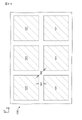
- FIG. 23 is a schematic plan view for explaining the distance between adjacent pixel electrodes.
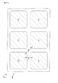
- FIG. 24 is a schematic plan view for explaining the distance between adjacent pixel electrodes, following FIG. 23.
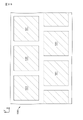
- the side portion of the pixel electrode 131 faces the adjacent pixel electrode 131 at a distance W1.
- the corner portions of the pixel electrode 131 face each other at a distance W2.
- the distance W1 ⁇ distance W2.
- the corners of the pixel electrode 131 tend to be rounded.
- the corner portions of the pixel electrodes 131 face each other at a distance W3.
- FIG. 25 is a schematic plan view for explaining an arrangement example of the pixel electrodes that suppresses the expansion of the diagonal distance of the pixel electrodes.
- the pixel electrodes 131 are arranged in a delta shape. This makes it possible to suppress fluctuations in the distance between adjacent pixel electrodes.
- island-shaped protrusions on the portions where the corners of the pixel electrodes 131 face each other.
- FIG. 26 is a schematic plan view for explaining an arrangement example in which the expansion of the diagonal distance of the pixel electrodes is suppressed by arranging the island-shaped region of the same layer as the pixel electrodes between the pixel electrodes. ..
- the island-shaped protrusion 131L is configured by using the same conductive material layer as the pixel electrode 131. As a result, the spread of the slit at the corner portion of the pixel electrode 131 can be suppressed.
- the liquid crystal display element according to the present disclosure described above is used in all fields of displaying a video signal input to an electronic device or a video signal generated in the electronic device as an image or a video. It can be used as a display unit of an electronic device of. As an example, it can be used as a display unit of, for example, a television set, a digital still camera, a notebook personal computer, a portable terminal device such as a mobile phone, a video camera, a head mount display (head-mounted display), or the like.
- the liquid crystal display element of the present disclosure includes a modular one having a sealed configuration.
- the display module may be provided with a circuit unit for inputting / outputting a signal or the like from the outside to the pixel array unit, a flexible printed circuit (FPC), or the like.
- FPC flexible printed circuit
- a projection type display device is illustrated, and as an electronic device provided with the display device using the liquid crystal display element of the present disclosure, a digital still camera, And a head-mounted display is illustrated.
- the specific examples exemplified here are only examples, and are not limited to these.
- FIG. 27 is a conceptual diagram of a projection type display device using the liquid crystal display element of the present disclosure.
- the display device 400 includes a liquid crystal display element 1 and a light source unit 410 that irradiates the liquid crystal display element 1 with light. More specifically, the display device 400 includes a light source unit 410, an illumination optical system 420, a liquid crystal display element 1, an image control circuit 430 for driving the liquid crystal display element 1, a projection optical system 440, a screen 450, and the like. ..
- the light source unit 410 can be composed of, for example, various lamps such as xenon lamps and semiconductor light emitting elements such as light emitting diodes.
- the illumination optical system 420 is used to guide the light from the light source unit 410 to the liquid crystal display element 1, and is composed of optical elements such as a prism and a dichroic mirror.
- the liquid crystal display element 1 acts as a light bulb, and an image is projected on the screen 450 via the projection optical system 440.
- FIG. 28 is an external view of an interchangeable lens type single-lens reflex type digital still camera, the front view thereof is shown in FIG. 28A, and the rear view thereof is shown in FIG. 28B.
- An interchangeable lens single-lens reflex type digital still camera has, for example, an interchangeable photographing lens unit (interchangeable lens) 512 on the front right side of the camera body (camera body) 511, and is held by the photographer on the front left side. It has a grip portion 513 for the purpose.
- interchangeable photographing lens unit interchangeable lens
- a monitor 514 is provided in the center of the back of the camera body 511.
- a viewfinder (eyepiece window) 515 is provided on the upper part of the monitor 514. By looking into the viewfinder 515, the photographer can visually recognize the optical image of the subject guided from the photographing lens unit 512 and determine the composition.
- the display device of the present disclosure can be used as the viewfinder 515. That is, the interchangeable lens type single-lens reflex type digital still camera according to this example is manufactured by using the display device of the present disclosure as the viewfinder 515.
- FIG. 29 is an external view of the head-mounted display.
- the head-mounted display has, for example, ear hooks 612 for being worn on the user's head on both sides of the eyeglass-shaped display unit 611.
- the display device of the present disclosure can be used as the display unit 611. That is, the head-mounted display according to this example is manufactured by using the display device of the present disclosure as the display unit 611.
- FIG. 30 is an external view of a see-through head-mounted display.
- the see-through head-mounted display 711 is composed of a main body 712, an arm 713, and a lens barrel 714.
- the main body 712 is connected to the arm 713 and the glasses 700. Specifically, the end portion of the main body portion 712 in the long side direction is connected to the arm 713, and one side of the side surface of the main body portion 712 is connected to the eyeglasses 700 via a connecting member.
- the main body portion 712 may be directly attached to the head of the human body.
- the main body 712 incorporates a control board for controlling the operation of the see-through head-mounted display 711 and a display unit.
- the arm 713 connects the main body 712 and the lens barrel 714, and supports the lens barrel 714. Specifically, the arm 713 is coupled to the end of the main body 712 and the end of the lens barrel 714, respectively, to fix the lens barrel 714. Further, the arm 713 has a built-in signal line for communicating data related to an image provided from the main body 712 to the lens barrel 714.
- the lens barrel 714 projects the image light provided from the main body 712 via the arm 713 toward the eyes of the user who wears the see-through head-mounted display 711 through the eyepiece.
- the display device of the present disclosure can be used for the display unit of the main body unit 712.
- the technique according to the present disclosure can be applied to various products.
- the technology according to the present disclosure is any kind of movement such as an automobile, an electric vehicle, a hybrid electric vehicle, a motorcycle, a bicycle, a personal mobility, an airplane, a drone, a ship, a robot, a construction machine, and an agricultural machine (tractor). It may be realized as a device mounted on the body.
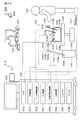
- FIG. 31 is a block diagram showing a schematic configuration example of a vehicle control system 7000, which is an example of a mobile control system to which the technique according to the present disclosure can be applied.
- the vehicle control system 7000 includes a plurality of electronic control units connected via a communication network 7010.
- the vehicle control system 7000 includes a drive system control unit 7100, a body system control unit 7200, a battery control unit 7300, an outside information detection unit 7400, an in-vehicle information detection unit 7500, and an integrated control unit 7600. ..
- the communication network 7010 connecting these plurality of control units conforms to any standard such as CAN (Controller Area Network), LIN (Local Interconnect Network), LAN (Local Area Network) or FlexRay (registered trademark). It may be an in-vehicle communication network.
- CAN Controller Area Network
- LIN Local Interconnect Network
- LAN Local Area Network
- FlexRay registered trademark
- Each control unit includes a microcomputer that performs arithmetic processing according to various programs, a storage unit that stores programs executed by the microcomputer or parameters used for various arithmetic, and a drive circuit that drives various controlled devices. To prepare for.
- Each control unit is provided with a network I / F for communicating with other control units via the communication network 7010, and is connected to devices or sensors inside and outside the vehicle by wired communication or wireless communication.
- a communication I / F for performing communication is provided. In FIG.
- the functional configuration of the integrated control unit 7600 includes a microcomputer 7610, a general-purpose communication I / F7620, a dedicated communication I / F7630, a positioning unit 7640, a beacon receiving unit 7650, an in-vehicle device I / F7660, and an audio image output unit 7670.
- the vehicle-mounted network I / F 7680 and the storage unit 7690 are illustrated.
- Other control units also include a microcomputer, a communication I / F, a storage unit, and the like.
- the drive system control unit 7100 controls the operation of the device related to the drive system of the vehicle according to various programs.
- the drive system control unit 7100 has a driving force generator for generating the driving force of the vehicle such as an internal combustion engine or a driving motor, a driving force transmission mechanism for transmitting the driving force to the wheels, and a steering angle of the vehicle. It functions as a control device such as a steering mechanism for adjusting and a braking device for generating braking force of the vehicle.
- the drive system control unit 7100 may have a function as a control device such as ABS (Antilock Brake System) or ESC (Electronic Stability Control).
- the vehicle state detection unit 7110 is connected to the drive system control unit 7100.
- the vehicle state detection unit 7110 may include, for example, a gyro sensor that detects the angular speed of the axial rotation motion of the vehicle body, an acceleration sensor that detects the acceleration of the vehicle, an accelerator pedal operation amount, a brake pedal operation amount, or steering wheel steering. It includes at least one of sensors for detecting angles, engine speeds, wheel speeds, and the like.
- the drive system control unit 7100 performs arithmetic processing using a signal input from the vehicle state detection unit 7110, and controls an internal combustion engine, a drive motor, an electric power steering device, a brake device, and the like.
- the body system control unit 7200 controls the operation of various devices mounted on the vehicle body according to various programs.
- the body system control unit 7200 functions as a keyless entry system, a smart key system, a power window device, or a control device for various lamps such as headlamps, back lamps, brake lamps, turn signals or fog lamps.
- a radio wave transmitted from a portable device that substitutes for a key or signals of various switches may be input to the body system control unit 7200.
- the body system control unit 7200 receives inputs of these radio waves or signals and controls a vehicle door lock device, a power window device, a lamp, and the like.
- the battery control unit 7300 controls the secondary battery 7310, which is the power supply source of the drive motor, according to various programs. For example, information such as the battery temperature, the battery output voltage, or the remaining capacity of the battery is input to the battery control unit 7300 from the battery device including the secondary battery 7310. The battery control unit 7300 performs arithmetic processing using these signals, and controls the temperature control of the secondary battery 7310 or the cooling device provided in the battery device.
- the outside information detection unit 7400 detects information outside the vehicle equipped with the vehicle control system 7000.
- the image pickup unit 7410 and the vehicle exterior information detection unit 7420 is connected to the vehicle exterior information detection unit 7400.
- the image pickup unit 7410 includes at least one of a ToF (Time Of Flight) camera, a stereo camera, a monocular camera, an infrared camera, and other cameras.
- the vehicle outside information detection unit 7420 is used, for example, to detect the current weather or an environment sensor for detecting the weather, or other vehicles, obstacles, pedestrians, etc. around the vehicle equipped with the vehicle control system 7000. At least one of the ambient information detection sensors is included.
- the environment sensor may be, for example, at least one of a raindrop sensor that detects rainy weather, a fog sensor that detects fog, a sunshine sensor that detects the degree of sunshine, and a snow sensor that detects snowfall.
- the ambient information detection sensor may be at least one of an ultrasonic sensor, a radar device, and a LIDAR (Light Detection and Ringing, Laser Imaging Detection and Ringing) device.
- the image pickup unit 7410 and the vehicle exterior information detection unit 7420 may be provided as independent sensors or devices, or may be provided as a device in which a plurality of sensors or devices are integrated.
- FIG. 32 shows an example of the installation position of the image pickup unit 7410 and the vehicle exterior information detection unit 7420.
- the image pickup unit 7910, 7912, 7914, 7916, 7918 are provided, for example, at at least one of the front nose, side mirror, rear bumper, back door, and upper part of the windshield of the vehicle interior of the vehicle 7900.
- the image pickup unit 7910 provided in the front nose and the image pickup section 7918 provided in the upper part of the windshield in the vehicle interior mainly acquire an image in front of the vehicle 7900.
- the image pickup units 7912 and 7914 provided in the side mirrors mainly acquire images of the side of the vehicle 7900.
- the image pickup unit 7916 provided in the rear bumper or the back door mainly acquires an image of the rear of the vehicle 7900.
- the image pickup unit 7918 provided on the upper part of the windshield in the vehicle interior is mainly used for detecting a preceding vehicle, a pedestrian, an obstacle, a traffic light, a traffic sign, a lane, or the like.
- FIG. 32 shows an example of the shooting range of each of the imaging units 7910, 7912, 7914, 7916.
- the imaging range a indicates the imaging range of the imaging unit 7910 provided on the front nose
- the imaging ranges b and c indicate the imaging range of the imaging units 7912 and 7914 provided on the side mirrors, respectively
- the imaging range d indicates the imaging range d.
- the imaging range of the imaging unit 7916 provided on the rear bumper or the back door is shown. For example, by superimposing the image data captured by the image pickup units 7910, 7912, 7914, 7916, a bird's-eye view image of the vehicle 7900 can be obtained.
- the vehicle exterior information detection unit 7920, 7922, 7924, 7926, 7928, 7930 provided on the front, rear, side, corner and the upper part of the windshield in the vehicle interior of the vehicle 7900 may be, for example, an ultrasonic sensor or a radar device.
- the vehicle exterior information detection units 7920, 7926, 7930 provided on the front nose, rear bumper, back door, and upper part of the windshield in the vehicle interior of the vehicle 7900 may be, for example, a lidar device.
- These out-of-vehicle information detection units 7920 to 7930 are mainly used for detecting a preceding vehicle, a pedestrian, an obstacle, or the like.
- the vehicle outside information detection unit 7400 causes the image pickup unit 7410 to capture an image of the outside of the vehicle and receives the captured image data. Further, the vehicle outside information detection unit 7400 receives the detection information from the connected vehicle outside information detection unit 7420.
- the vehicle exterior information detection unit 7420 is an ultrasonic sensor, a radar device, or a lidar device
- the vehicle exterior information detection unit 7400 transmits ultrasonic waves, electromagnetic waves, or the like, and receives received reflected wave information.
- the out-of-vehicle information detection unit 7400 may perform object detection processing or distance detection processing such as a person, a vehicle, an obstacle, a sign, or a character on a road surface based on the received information.
- the out-of-vehicle information detection unit 7400 may perform an environment recognition process for recognizing rainfall, fog, road surface conditions, etc. based on the received information.
- the out-of-vehicle information detection unit 7400 may calculate the distance to an object outside the vehicle based on the received information.
- the vehicle outside information detection unit 7400 may perform image recognition processing or distance detection processing for recognizing a person, a vehicle, an obstacle, a sign, a character on the road surface, or the like based on the received image data.
- the vehicle exterior information detection unit 7400 performs processing such as distortion correction or alignment on the received image data, and synthesizes image data captured by different image pickup units 7410 to generate a bird's-eye view image or a panoramic image. May be good.
- the vehicle exterior information detection unit 7400 may perform a viewpoint conversion process using image data captured by different image pickup units 7410.
- the in-vehicle information detection unit 7500 detects the in-vehicle information.
- a driver state detection unit 7510 that detects the state of the driver is connected to the in-vehicle information detection unit 7500.
- the driver state detection unit 7510 may include a camera that captures the driver, a biosensor that detects the driver's biological information, a microphone that collects sound in the vehicle interior, and the like.
- the biosensor is provided on, for example, a seat surface or a steering wheel, and detects biometric information of a passenger sitting on the seat or a driver holding the steering wheel.
- the in-vehicle information detection unit 7500 may calculate the degree of fatigue or concentration of the driver based on the detection information input from the driver state detection unit 7510, and determines whether or not the driver is dozing. You may.
- the in-vehicle information detection unit 7500 may perform processing such as noise canceling processing on the collected audio signal.
- the integrated control unit 7600 controls the overall operation in the vehicle control system 7000 according to various programs.
- An input unit 7800 is connected to the integrated control unit 7600.
- the input unit 7800 is realized by a device that can be input-operated by the occupant, such as a touch panel, a button, a microphone, a switch, or a lever. Data obtained by recognizing the voice input by the microphone may be input to the integrated control unit 7600.
- the input unit 7800 may be, for example, a remote control device using infrared rays or other radio waves, or an external connection device such as a mobile phone or a PDA (Personal Digital Assistant) corresponding to the operation of the vehicle control system 7000. You may.
- the input unit 7800 may be, for example, a camera, in which case the passenger can input information by gesture. Alternatively, data obtained by detecting the movement of the wearable device worn by the passenger may be input. Further, the input unit 7800 may include, for example, an input control circuit that generates an input signal based on the information input by the passenger or the like using the above input unit 7800 and outputs the input signal to the integrated control unit 7600. By operating the input unit 7800, the passenger or the like inputs various data to the vehicle control system 7000 and instructs the processing operation.
- the storage unit 7690 may include a ROM (Read Only Memory) for storing various programs executed by the microcomputer, and a RAM (Random Access Memory) for storing various parameters, calculation results, sensor values, and the like. Further, the storage unit 7690 may be realized by a magnetic storage device such as an HDD (Hard Disc Drive), a semiconductor storage device, an optical storage device, an optical magnetic storage device, or the like.
- ROM Read Only Memory
- RAM Random Access Memory
- the general-purpose communication I / F 7620 is a general-purpose communication I / F that mediates communication with various devices existing in the external environment 7750.
- General-purpose communication I / F7620 is a cellular communication protocol such as GSM (registered trademark) (Global System of Mobile communications), WiMAX, LTE (LongTermEvolution) or LTE-A (LTE-Advanced), or wireless LAN (Wi-Fi).
- GSM Global System of Mobile communications
- WiMAX Wireless F
- LTE LongTermEvolution
- LTE-A LTE-Advanced
- Wi-Fi wireless LAN
- Other wireless communication protocols such as (also referred to as (registered trademark)) and Bluetooth (registered trademark) may be implemented.
- the general-purpose communication I / F7620 connects to a device (for example, an application server or a control server) existing on an external network (for example, the Internet, a cloud network, or a business-specific network) via a base station or an access point, for example. You may. Further, the general-purpose communication I / F7620 uses, for example, P2P (Peer To Peer) technology to provide a terminal existing in the vicinity of the vehicle (for example, a driver, a pedestrian or a store terminal, or an MTC (Machine Type Communication) terminal). May be connected with.
- P2P Peer To Peer
- MTC Machine Type Communication
- the dedicated communication I / F 7630 is a communication I / F that supports a communication protocol formulated for use in a vehicle.
- the dedicated communication I / F7630 is a standard protocol such as WAVE (Wireless Access in Vehicle Environment), DSRC (Dedicated Short Range Communications), which is a combination of the lower layer IEEE802.11p and the upper layer IEEE1609, or a cellular communication protocol. May be implemented.
- Dedicated communication I / F7630 is typically vehicle-to-vehicle (Vehicle to Vehicle) communication, road-to-vehicle (Vehicle to Infrastructure) communication, vehicle-to-home (Vehicle to Home) communication, and pedestrian-to-vehicle (Vehicle to Pedestrian) communication. Carry out V2X communication, a concept that includes one or more of the communications.
- the positioning unit 7640 receives, for example, a GNSS signal from a GNSS (Global Navigation Satellite System) satellite (for example, a GPS signal from a GPS (Global Positioning System) satellite) and executes positioning, and performs positioning, and the latitude, longitude, and altitude of the vehicle. Generate location information including.
- the positioning unit 7640 may specify the current position by exchanging signals with the wireless access point, or may acquire position information from a terminal such as a mobile phone, PHS, or smartphone having a positioning function.
- the beacon receiving unit 7650 receives, for example, a radio wave or an electromagnetic wave transmitted from a radio station or the like installed on a road, and acquires information such as a current position, a traffic jam, a road closure, or a required time.
- the function of the beacon receiving unit 7650 may be included in the above-mentioned dedicated communication I / F 7630.
- the in-vehicle device I / F 7660 is a communication interface that mediates the connection between the microcomputer 7610 and various in-vehicle devices 7760 existing in the vehicle.
- the in-vehicle device I / F7660 may establish a wireless connection using a wireless communication protocol such as wireless LAN, Bluetooth®, NFC (Near Field Communication) or WUSB (Wireless USB).
- a wireless communication protocol such as wireless LAN, Bluetooth®, NFC (Near Field Communication) or WUSB (Wireless USB.
- the in-vehicle device I / F7660 can be connected to USB (Universal Serial Bus), HDMI (registered trademark) (High-Definition Multimedia Interface), or MHL (Mobile) via a connection terminal (and a cable if necessary) (not shown).
- a wired connection such as High-definition Link may be established.
- the in-vehicle device 7760 may include, for example, at least one of a passenger's mobile device or wearable device, or information device carried in or attached to the vehicle. Further, the in-vehicle device 7760 may include a navigation device that searches for a route to an arbitrary destination.
- the in-vehicle device I / F 7660 exchanges control signals or data signals with these in-vehicle devices 7760.
- the in-vehicle network I / F7680 is an interface that mediates communication between the microcomputer 7610 and the communication network 7010.
- the vehicle-mounted network I / F7680 transmits / receives signals and the like according to a predetermined protocol supported by the communication network 7010.
- the microcomputer 7610 of the integrated control unit 7600 is via at least one of general-purpose communication I / F7620, dedicated communication I / F7630, positioning unit 7640, beacon receiving unit 7650, in-vehicle device I / F7660, and in-vehicle network I / F7680. Based on the information acquired in the above, the vehicle control system 7000 is controlled according to various programs. For example, the microcomputer 7610 calculates the control target value of the driving force generator, the steering mechanism, or the braking device based on the acquired information inside and outside the vehicle, and outputs a control command to the drive system control unit 7100. May be good.
- the microcomputer 7610 realizes ADAS (Advanced Driver Assistance System) functions including vehicle collision avoidance or impact mitigation, follow-up driving based on inter-vehicle distance, vehicle speed maintenance driving, vehicle collision warning, vehicle lane deviation warning, and the like. Cooperative control may be performed for the purpose of.
- the microcomputer 7610 automatically travels autonomously without relying on the driver's operation by controlling the driving force generator, steering mechanism, braking device, etc. based on the acquired information on the surroundings of the vehicle. Coordinated control may be performed for the purpose of driving or the like.
- the microcomputer 7610 has information acquired via at least one of a general-purpose communication I / F7620, a dedicated communication I / F7630, a positioning unit 7640, a beacon receiving unit 7650, an in-vehicle device I / F7660, and an in-vehicle network I / F7680. Based on the above, three-dimensional distance information between the vehicle and an object such as a surrounding structure or a person may be generated, and local map information including the peripheral information of the current position of the vehicle may be created. Further, the microcomputer 7610 may predict the danger of a vehicle collision, a pedestrian or the like approaching or entering a closed road, and generate a warning signal based on the acquired information.
- the warning signal may be, for example, a signal for generating a warning sound or lighting a warning lamp.
- the audio image output unit 7670 transmits an output signal of at least one of audio and image to an output device capable of visually or audibly notifying information to the passenger or the outside of the vehicle.
- an audio speaker 7710, a display unit 7720, and an instrument panel 7730 are exemplified as output devices.
- the display unit 7720 may include, for example, at least one of an onboard display and a head-up display.
- the display unit 7720 may have an AR (Augmented Reality) display function.
- the output device may be other devices such as headphones, wearable devices such as eyeglass-type displays worn by passengers, projectors or lamps other than these devices.
- the display device displays the results obtained by various processes performed by the microcomputer 7610 or the information received from other control units in various formats such as texts, images, tables, and graphs. Display visually.
- the audio output device converts an audio signal composed of reproduced audio data, acoustic data, or the like into an analog signal and outputs the audio signal audibly.
- At least two control units connected via the communication network 7010 may be integrated as one control unit.
- each control unit may be composed of a plurality of control units.
- the vehicle control system 7000 may include another control unit (not shown).
- the other control unit may have a part or all of the functions carried out by any of the control units. That is, as long as information is transmitted and received via the communication network 7010, predetermined arithmetic processing may be performed by any of the control units.
- a sensor or device connected to any control unit may be connected to another control unit, and a plurality of control units may send and receive detection information to and from each other via the communication network 7010. .
- the technique according to the present disclosure can be applied to, for example, the display unit of an output device capable of visually or audibly notifying information among the configurations described above.
- FIG. 33 is a diagram schematically showing the overall configuration of the operating room system 5100 to which the technique according to the present disclosure can be applied.
- the operating room system 5100 is configured by connecting devices installed in the operating room in a coordinated manner via an audiovisual controller (AV Controller) 5107 and an operating room control device 5109.
- AV Controller audiovisual controller
- FIG. 33 various devices can be installed in the operating room.
- various device groups 5101 for endoscopic surgery a sealing camera 5187 provided on the ceiling of the operating room to capture the operator's hand, and an operating room provided on the ceiling of the operating room.
- the operating room camera 5189 that captures the whole situation, a plurality of display devices 5103A to 5103D, a recorder 5105, a patient bed 5183, and an illumination 5191 are illustrated.
- the device group 5101 belongs to the endoscopic surgery system 5113 described later, and includes an endoscope, a display device for displaying an image captured by the endoscope, and the like.
- Each device belonging to the endoscopic surgery system 5113 is also referred to as a medical device.
- the display devices 5103A to 5103D, the recorder 5105, the patient bed 5183 and the lighting 5191 are devices provided in the operating room, for example, separately from the endoscopic surgery system 5113.
- Each of these devices that do not belong to the endoscopic surgery system 5113 is also referred to as a non-medical device.
- the audiovisual controller 5107 and / or the operating room control device 5109 controls the operation of these medical devices and non-medical devices in cooperation with each other.
- the audiovisual controller 5107 comprehensively controls processing related to image display in medical devices and non-medical devices.
- the device group 5101, the ceiling camera 5187, and the operating room camera 5189 have a function of transmitting information to be displayed during the operation (hereinafter, also referred to as display information).
- It may be a device (hereinafter, also referred to as a source device).
- the display devices 5103A to 5103D may be devices for outputting display information (hereinafter, also referred to as output destination devices).
- the recorder 5105 may be a device corresponding to both the source device and the output destination device.
- the audiovisual controller 5107 controls the operation of the source device and the output destination device, acquires display information from the source device, and transmits the display information to the output destination device for display or recording.
- the displayed information includes various images captured during the surgery, various information related to the surgery (for example, physical information of the patient, past test results, information about the surgical procedure, etc.).
- the audiovisual controller 5107 may transmit information about the image of the surgical site in the body cavity of the patient captured by the endoscope as display information from the device group 5101.
- the ceiling camera 5187 may transmit information about the image at the operator's hand captured by the ceiling camera 5187 as display information.
- the operating room camera 5189 may transmit as display information information about an image showing the state of the entire operating room captured by the operating room camera 5189. If the operating room system 5100 has another device having an image pickup function, the audiovisual controller 5107 acquires information about the image captured by the other device from the other device as display information. You may.
- the recorder 5105 records information about these images captured in the past by the audiovisual controller 5107.
- the audiovisual controller 5107 can acquire information about the previously captured image from the recorder 5105 as display information.
- various information about the operation may be recorded in advance in the recorder 5105.
- the audiovisual controller 5107 causes at least one of the display devices 5103A to 5103D, which is the output destination device, to display the acquired display information (that is, images taken during the surgery and various information related to the surgery).
- the display device 5103A is a display device suspended from the ceiling of the operating room
- the display device 5103B is a display device installed on the wall surface of the operating room
- the display device 5103C is the display device in the operating room. It is a display device installed on a desk
- the display device 5103D is a mobile device having a display function (for example, a tablet PC (Personal Computer)).
- the operating room system 5100 may include a device outside the operating room.
- the device outside the operating room may be, for example, a server connected to a network constructed inside or outside the hospital, a PC used by medical staff, a projector installed in a conference room of the hospital, or the like.
- the audiovisual controller 5107 can also display the display information on the display device of another hospital via a video conference system or the like for telemedicine.
- the operating room control device 5109 comprehensively controls processing other than processing related to image display in non-medical equipment.
- the operating room control device 5109 controls the drive of the patient bed 5183, the ceiling camera 5187, the operating room camera 5189, and the lighting 5191.
- the operating room system 5100 is provided with a centralized operation panel 5111, and the user can give an instruction regarding image display to the audiovisual controller 5107 or the operating room control device 5109 via the centralized operation panel 5111. On the other hand, instructions on the operation of non-medical devices can be given.
- the centralized operation panel 5111 is configured by providing a touch panel on the display surface of the display device.
- FIG. 34 is a diagram showing a display example of the operation screen on the centralized operation panel 5111.
- FIG. 34 shows, as an example, an operation screen corresponding to a case where the operating room system 5100 is provided with two display devices as output destination devices.
- the operation screen 5193 is provided with a source selection area 5195, a preview area 5197, and a control area 5201.
- the source device provided in the operating room system 5100 and the thumbnail screen showing the display information possessed by the source device are linked and displayed.
- the user can select the display information to be displayed on the display device from any of the source devices displayed in the source selection area 5195.
- a preview of the screen displayed on the two display devices which are the output destination devices, is displayed.
- four images are displayed in PinP on one display device.
- the four images correspond to the display information transmitted from the source device selected in the source selection area 5195.
- one is displayed relatively large as the main image and the remaining three are displayed relatively small as the sub-image.
- the user can switch the main image and the sub image by appropriately selecting the area in which the four images are displayed.
- a status display area 5199 is provided at the lower part of the area where the four images are displayed, and the status related to the surgery (for example, the elapsed time of the surgery, the physical information of the patient, etc.) is appropriately displayed in the area. obtain.
- the source operation area 5203 in which the GUI (Graphical User Interface) component for operating the source device is displayed, and the GUI component for operating the output destination device. Is provided with an output destination operation area 5205 and.
- the source operation area 5203 is provided with GUI components for performing various operations (pan, tilt, and zoom) on the camera in the source device having an image pickup function. The user can operate the operation of the camera in the originating device by appropriately selecting these GUI components.
- the source device selected in the source selection area 5195 is a recorder (that is, in the preview area 5197, an image recorded in the past by the recorder is displayed.
- the source operation area 5203 may be provided with a GUI component for performing operations such as reproduction, reproduction stop, rewind, and fast forward of the image.
- GUI parts for performing various operations for the display on the display device which is the output destination device are provided. It is provided. The user can operate the display on the display device by appropriately selecting these GUI components.
- the operation screen displayed on the centralized operation panel 5111 is not limited to the illustrated example, and the user can use the audiovisual controller 5107 and the operating room control device 5109 provided in the operating room system 5100 via the centralized operation panel 5111. Operational inputs to each device that can be controlled may be possible.
- FIG. 35 is a diagram showing an example of an operation in which the operating room system described above is applied.
- the ceiling camera 5187 and the operating room camera 5189 are provided on the ceiling of the operating room, and can photograph the hand of the surgeon (doctor) 5181 who treats the affected part of the patient 5185 on the patient bed 5183 and the entire operating room. Is.
- the ceiling camera 5187 and the surgical field camera 5189 may be provided with a magnification adjustment function, a focal length adjustment function, a shooting direction adjustment function, and the like.
- the illumination 5191 is provided on the ceiling of the operating room and illuminates at least the hand of the surgeon 5181.
- the illumination 5191 may be capable of appropriately adjusting the amount of irradiation light, the wavelength (color) of the irradiation light, the irradiation direction of the light, and the like.
- the endoscopic surgery system 5113, patient bed 5183, sealing camera 5187, operating room camera 5189 and lighting 5191 are via an audiovisual controller 5107 and an operating room control device 5109 (not shown in FIG. 35), as shown in FIG. Are connected so that they can cooperate with each other.
- the centralized operation panel 5111 is provided in the operating room, and as described above, the user can appropriately operate these devices existing in the operating room via the centralized operation panel 5111.
- the endoscopic surgery system 5113 includes an endoscope 5115, other surgical tools 5131, a support arm device 5141 that supports the endoscope 5115, and various devices for endoscopic surgery. It is composed of a cart 5151 on which the
- trocca 5139a-5139d In endoscopic surgery, instead of cutting the abdominal wall to open the abdomen, multiple tubular opening devices called trocca 5139a-5139d are punctured into the abdominal wall. Then, from the troccers 5139a to 5139d, the lens barrel 5117 of the endoscope 5115 and other surgical tools 5131 are inserted into the body cavity of the patient 5185.
- other surgical tools 5131 a pneumoperitoneum tube 5133, an energy treatment tool 5135, and forceps 5137 are inserted into the body cavity of patient 5185.
- the energy treatment tool 5135 is a treatment tool for incising and peeling a tissue, sealing a blood vessel, or the like by using a high frequency current or ultrasonic vibration.
- the surgical tool 5131 shown is only an example, and various surgical tools generally used in endoscopic surgery such as a sword and a retractor may be used as the surgical tool 5131.
- the image of the surgical site in the body cavity of the patient 5185 taken by the endoscope 5115 is displayed on the display device 5155.
- the surgeon 5181 performs a procedure such as excising the affected area by using the energy treatment tool 5135 or the forceps 5137 while viewing the image of the surgical site displayed on the display device 5155 in real time.
- the pneumoperitoneum tube 5133, the energy treatment tool 5135, and the forceps 5137 are supported by the surgeon 5181 or an assistant during the operation.
- the support arm device 5141 includes an arm portion 5145 extending from the base portion 5143.
- the arm portion 5145 is composed of joint portions 5147a, 5147b, 5147c, and links 5149a, 5149b, and is driven by control from the arm control device 5159.
- the endoscope 5115 is supported by the arm portion 5145, and its position and posture are controlled. As a result, the stable position of the endoscope 5115 can be fixed.
- the endoscope 5115 is composed of a lens barrel 5117 in which a region having a predetermined length from the tip is inserted into the body cavity of the patient 5185, and a camera head 5119 connected to the base end of the lens barrel 5117. It is composed.
- the endoscope 5115 configured as a so-called rigid mirror having a rigid barrel 5117 is illustrated, but the endoscope 5115 is configured as a so-called flexible mirror having a flexible barrel 5117. May be good.
- An opening in which an objective lens is fitted is provided at the tip of the lens barrel 5117.
- a light source device 5157 is connected to the endoscope 5115, and the light generated by the light source device 5157 is guided to the tip of the lens barrel by a light guide extending inside the lens barrel 5117, and is an objective. It is irradiated toward the observation target in the body cavity of the patient 5185 through the lens.
- the endoscope 5115 may be a direct endoscope, a perspective mirror, or a side endoscope.
- An optical system and an image pickup element are provided inside the camera head 5119, and the reflected light (observation light) from the observation target is focused on the image pickup element by the optical system.
- the observation light is photoelectrically converted by the image pickup device, and an electric signal corresponding to the observation light, that is, an image signal corresponding to the observation image is generated.
- the image signal is transmitted to the camera control unit (CCU: Camera Control Unit) 5153 as RAW data.
- the camera head 5119 is equipped with a function of adjusting the magnification and the focal length by appropriately driving the optical system thereof.
- the camera head 5119 may be provided with a plurality of image pickup elements.
- a plurality of relay optical systems are provided inside the lens barrel 5117 in order to guide the observation light to each of the plurality of image pickup elements.
- the CCU5153 is composed of a CPU (Central Processing Unit), a GPU (Graphics Processing Unit), etc., and comprehensively controls the operations of the endoscope 5115 and the display device 5155.
- the CCU 5153 performs various image processing for displaying an image based on the image signal, such as a development process (demosaic process), on the image signal received from the camera head 5119.
- the CCU 5153 provides the image signal subjected to the image processing to the display device 5155.
- the audiovisual controller 5107 shown in FIG. 33 is connected to the CCU 5153.
- the CCU 5153 also provides the image processed image signal to the audiovisual controller 5107.
- the CCU 5153 transmits a control signal to the camera head 5119 and controls the driving thereof.
- the control signal may include information about imaging conditions such as magnification and focal length.
- the information regarding the imaging condition may be input via the input device 5161 or may be input via the centralized operation panel 5111 described above.
- the display device 5155 displays an image based on the image signal processed by the CCU 5153 under the control of the CCU 5153.
- the endoscope 5115 is compatible with high-resolution shooting such as 4K (horizontal pixel number 3840 x vertical pixel number 2160) or 8K (horizontal pixel number 7680 x vertical pixel number 4320), and / or 3D display.
- a display device capable of displaying a high resolution and / or a device capable of displaying in 3D can be used.
- a display device 5155 having a size of 55 inches or more is used for high-resolution shooting such as 4K or 8K, a further immersive feeling can be obtained.
- a plurality of display devices 5155 having different resolutions and sizes may be provided depending on the application.
- the light source device 5157 is composed of, for example, a light source such as an LED (light emission diode), and supplies irradiation light for photographing the surgical site to the endoscope 5115.
- a light source such as an LED (light emission diode)
- the arm control device 5159 is configured by a processor such as a CPU, and operates according to a predetermined program to control the drive of the arm portion 5145 of the support arm device 5141 according to a predetermined control method.
- the input device 5161 is an input interface for the endoscopic surgery system 5113.
- the user can input various information and input instructions to the endoscopic surgery system 5113 via the input device 5161.
- the user inputs various information related to the surgery, such as physical information of the patient and information about the surgical procedure, via the input device 5161.
- the user is instructed to drive the arm portion 5145 via the input device 5161 and an instruction to change the imaging conditions (type of irradiation light, magnification, focal length, etc.) by the endoscope 5115.
- Instructions to drive the energy treatment tool 5135, etc. are input.
- the type of the input device 5161 is not limited, and the input device 5161 may be various known input devices.
- the input device 5161 for example, a mouse, a keyboard, a touch panel, a switch, a foot switch 5171 and / or a lever and the like can be applied.
- the touch panel may be provided on the display surface of the display device 5155.
- the input device 5161 is a device worn by the user, such as a glasses-type wearable device or an HMD (Head Mounted Display), and various inputs are made according to the user's gesture and line of sight detected by these devices. Is done. Further, the input device 5161 includes a camera capable of detecting the movement of the user, and various inputs are performed according to the gesture and the line of sight of the user detected from the image captured by the camera. Further, the input device 5161 includes a microphone capable of picking up the voice of the user, and various inputs are performed by voice via the microphone.
- a glasses-type wearable device or an HMD Head Mounted Display
- the input device 5161 is configured to be able to input various information in a non-contact manner, so that a user who belongs to a clean area (for example, an operator 5181) can operate a device belonging to the unclean area in a non-contact manner. Is possible. In addition, the user can operate the device without taking his / her hand off the surgical tool that he / she has, which improves the convenience of the user.
- a clean area for example, an operator 5181
- the user can operate the device without taking his / her hand off the surgical tool that he / she has, which improves the convenience of the user.
- the treatment tool control device 5163 controls the drive of the energy treatment tool 5135 for cauterizing, incising, sealing blood vessels, and the like.
- the pneumoperitoneum device 5165 gas in the body cavity through the pneumoperitoneum tube 5133 in order to inflate the body cavity of the patient 5185 for the purpose of securing the field of view by the endoscope 5115 and securing the operator's work space. Is sent.
- the recorder 5167 is a device capable of recording various information related to surgery.
- the printer 5169 is a device capable of printing various information related to surgery in various formats such as text, images, and graphs.
- the support arm device 5141 includes a base portion 5143 that is a base, and an arm portion 5145 that extends from the base portion 5143.
- the arm portion 5145 is composed of a plurality of joint portions 5147a, 5147b, 5147c and a plurality of links 5149a, 5149b connected by the joint portions 5147b, but in FIG. 35, for the sake of simplicity.
- the configuration of the arm portion 5145 is simplified and illustrated.
- the shapes, numbers and arrangements of the joint portions 5147a to 5147c and the links 5149a and 5149b, the direction of the rotation axis of the joint portions 5147a to 5147c, and the like are appropriately set so that the arm portion 5145 has a desired degree of freedom.
- the arm portion 5145 may be preferably configured to have more than 6 degrees of freedom.
- the endoscope 5115 can be freely moved within the movable range of the arm portion 5145, so that the lens barrel 5117 of the endoscope 5115 can be inserted into the body cavity of the patient 5185 from a desired direction. It will be possible.
- An actuator is provided in the joint portions 5147a to 5147c, and the joint portions 5147a to 5147c are configured to be rotatable around a predetermined rotation axis by driving the actuator.
- the arm control device 5159 By controlling the drive of the actuator by the arm control device 5159, the rotation angles of the joint portions 5147a to 5147c are controlled, and the drive of the arm portion 5145 is controlled. Thereby, control of the position and posture of the endoscope 5115 can be realized.
- the arm control device 5159 can control the drive of the arm unit 5145 by various known control methods such as force control or position control.
- the surgeon 5181 appropriately inputs an operation input via the input device 5161 (including the foot switch 5171), and the arm control device 5159 appropriately controls the drive of the arm portion 5145 according to the operation input.
- the position and orientation of the endoscope 5115 may be controlled.
- the endoscope 5115 at the tip of the arm portion 5145 can be moved from an arbitrary position to an arbitrary position, and then fixedly supported at the moved position.
- the arm portion 5145 may be operated by a so-called master slave method.
- the arm portion 5145 can be remotely controlled by the user via an input device 5161 installed at a location away from the operating room.
- the arm control device 5159 When force control is applied, the arm control device 5159 receives an external force from the user, and the actuators of the joint portions 5147a to 5147c are arranged so that the arm portion 5145 moves smoothly according to the external force. So-called power assist control for driving may be performed.
- the arm portion 5145 when the user moves the arm portion 5145 while directly touching the arm portion 5145, the arm portion 5145 can be moved with a relatively light force. Therefore, the endoscope 5115 can be moved more intuitively and with a simpler operation, and the convenience of the user can be improved.
- the endoscope 5115 was supported by a doctor called a scopist.
- the position of the endoscope 5115 can be fixed more reliably without human intervention, so that an image of the surgical site can be stably obtained. , It becomes possible to perform surgery smoothly.
- the arm control device 5159 does not necessarily have to be provided on the cart 5151. Further, the arm control device 5159 does not necessarily have to be one device. For example, the arm control device 5159 may be provided at each joint portion 5147a to 5147c of the arm portion 5145 of the support arm device 5141, and the arm portion 5145 may be driven by the plurality of arm control devices 5159 cooperating with each other. Control may be realized.
- the light source device 5157 supplies the endoscope 5115 with the irradiation light for photographing the surgical site.
- the light source device 5157 is composed of, for example, an LED, a laser light source, or a white light source composed of a combination thereof.
- the white light source is configured by the combination of the RGB laser light sources, the output intensity and the output timing of each color (each wavelength) can be controlled with high accuracy, so that the white balance of the captured image is controlled by the light source device 5157. Can be adjusted.
- the observation target is irradiated with the laser light from each of the RGB laser light sources in a time-division manner, and the drive of the image sensor of the camera head 5119 is controlled in synchronization with the irradiation timing to correspond to each of RGB. It is also possible to capture the image in a time-division manner. According to this method, a color image can be obtained without providing a color filter in the image pickup device.
- the drive of the light source device 5157 may be controlled so as to change the intensity of the output light at predetermined time intervals.
- the drive of the image sensor of the camera head 5119 in synchronization with the timing of the change of the light intensity to acquire an image in time division and synthesizing the image, so-called high dynamic without blackout and overexposure. Range images can be generated.
- the light source device 5157 may be configured to be able to supply light in a predetermined wavelength band corresponding to special light observation.
- special light observation for example, by utilizing the wavelength dependence of light absorption in body tissue, the surface layer of the mucous membrane is irradiated with light in a narrower band than the irradiation light (that is, white light) during normal observation.
- narrow band imaging in which a predetermined tissue such as a blood vessel is photographed with high contrast, is performed.
- fluorescence observation may be performed in which an image is obtained by fluorescence generated by irradiating with excitation light.
- the body tissue is irradiated with excitation light to observe the fluorescence from the body tissue (autofluorescence observation), or a reagent such as indocyanine green (ICG) is locally injected into the body tissue and the body tissue is injected.
- a reagent that obtains a fluorescence image by irradiating with excitation light corresponding to the fluorescence wavelength of the reagent can be used.
- the light source device 5157 may be configured to be capable of supplying narrowband light and / or excitation light corresponding to such special light observation.
- FIG. 36 is a block diagram showing an example of the functional configuration of the camera head 5119 and the CCU 5153 shown in FIG. 35.
- the camera head 5119 has a lens unit 5121, an image pickup unit 5123, a drive unit 5125, a communication unit 5127, and a camera head control unit 5129 as its functions.
- the CCU 5153 has a communication unit 5173, an image processing unit 5175, and a control unit 5177 as its functions.
- the camera head 5119 and the CCU 5153 are bidirectionally connected by a transmission cable 5179 so as to be communicable.
- the lens unit 5121 is an optical system provided at a connection portion with the lens barrel 5117.
- the observation light taken in from the tip of the lens barrel 5117 is guided to the camera head 5119 and incident on the lens unit 5121.
- the lens unit 5121 is configured by combining a plurality of lenses including a zoom lens and a focus lens.
- the optical characteristics of the lens unit 5121 are adjusted so as to collect the observation light on the light receiving surface of the image pickup element of the image pickup unit 5123.
- the zoom lens and the focus lens are configured so that their positions on the optical axis can be moved in order to adjust the magnification and the focus of the captured image.
- the image pickup unit 5123 is composed of an image pickup element and is arranged after the lens unit 5121.
- the observation light that has passed through the lens unit 5121 is focused on the light receiving surface of the image pickup device, and an image signal corresponding to the observation image is generated by photoelectric conversion.
- the image signal generated by the image pickup unit 5123 is provided to the communication unit 5127.
- CMOS Complementary Metal Oxide Semiconductor
- the image pickup device for example, an image pickup device capable of capturing a high-resolution image of 4K or higher may be used.
- the image pickup element constituting the image pickup unit 5123 is configured to have a pair of image pickup elements for acquiring image signals for the right eye and the left eye corresponding to 3D display, respectively.
- the 3D display enables the surgeon 5181 to more accurately grasp the depth of the living tissue in the surgical site.
- the image pickup unit 5123 is composed of multiple plates, a plurality of lens units 5121 are also provided corresponding to each image pickup element.
- the image pickup unit 5123 does not necessarily have to be provided on the camera head 5119.
- the image pickup unit 5123 may be provided inside the lens barrel 5117, immediately after the objective lens.
- the drive unit 5125 is composed of an actuator, and the zoom lens and focus lens of the lens unit 5121 are moved by a predetermined distance along the optical axis under the control of the camera head control unit 5129. As a result, the magnification and focus of the image captured by the image pickup unit 5123 can be adjusted as appropriate.
- the communication unit 5127 is composed of a communication device for transmitting and receiving various information to and from the CCU 5153.
- the communication unit 5127 transmits the image signal obtained from the image pickup unit 5123 as RAW data to the CCU 5153 via the transmission cable 5179.
- the image signal is transmitted by optical communication.
- the surgeon 5181 performs the surgery while observing the condition of the affected area with the captured image, so for safer and more reliable surgery, the moving image of the surgical site is displayed in real time as much as possible. This is because it is required.
- the communication unit 5127 is provided with a photoelectric conversion module that converts an electric signal into an optical signal.
- the image signal is converted into an optical signal by the photoelectric conversion module, and then transmitted to the CCU 5153 via the transmission cable 5179.
- the communication unit 5127 receives a control signal for controlling the drive of the camera head 5119 from the CCU 5153.
- the control signal includes, for example, information to specify the frame rate of the captured image, information to specify the exposure value at the time of imaging, and / or information to specify the magnification and focus of the captured image. Contains information about the condition.
- the communication unit 5127 provides the received control signal to the camera head control unit 5129.
- the control signal from the CCU 5153 may also be transmitted by optical communication.
- the communication unit 5127 is provided with a photoelectric conversion module that converts an optical signal into an electric signal, and the control signal is converted into an electric signal by the photoelectric conversion module and then provided to the camera head control unit 5129.
- the image pickup conditions such as the frame rate, exposure value, magnification, and focus are automatically set by the control unit 5177 of the CCU 5153 based on the acquired image signal. That is, the so-called AE (Auto Exposure) function, AF (Auto Focus) function, and AWB (Auto White Balance) function are mounted on the endoscope 5115.
- AE Auto Exposure
- AF Automatic Focus
- AWB Automatic White Balance
- the camera head control unit 5129 controls the drive of the camera head 5119 based on the control signal from the CCU 5153 received via the communication unit 5127. For example, the camera head control unit 5129 controls the drive of the image pickup element of the image pickup unit 5123 based on the information to specify the frame rate of the image pickup image and / or the information to specify the exposure at the time of image pickup. Further, for example, the camera head control unit 5129 appropriately moves the zoom lens and the focus lens of the lens unit 5121 via the drive unit 5125 based on the information that the magnification and the focus of the captured image are specified.
- the camera head control unit 5129 may further have a function of storing information for identifying the lens barrel 5117 and the camera head 5119.
- the camera head 5119 can be made resistant to autoclave sterilization.
- the communication unit 5173 is composed of a communication device for transmitting and receiving various information to and from the camera head 5119.
- the communication unit 5173 receives an image signal transmitted from the camera head 5119 via the transmission cable 5179.
- the image signal can be suitably transmitted by optical communication.
- the communication unit 5173 is provided with a photoelectric conversion module that converts an optical signal into an electric signal.
- the communication unit 5173 provides the image processing unit 5175 with an image signal converted into an electric signal.
- the communication unit 5173 transmits a control signal for controlling the drive of the camera head 5119 to the camera head 5119.
- the control signal may also be transmitted by optical communication.
- the image processing unit 5175 performs various image processing on the image signal which is the RAW data transmitted from the camera head 5119.
- the image processing includes, for example, development processing, high image quality processing (band enhancement processing, super-resolution processing, NR (Noise reduction) processing and / or camera shake correction processing, etc.), and / or enlargement processing (electronic zoom processing). Etc., various known signal processing is included.
- the image processing unit 5175 performs detection processing on the image signal for performing AE, AF, and AWB.
- the image processing unit 5175 is composed of a processor such as a CPU or GPU, and the above-mentioned image processing and detection processing can be performed by operating the processor according to a predetermined program.
- the image processing unit 5175 is composed of a plurality of GPUs, the image processing unit 5175 appropriately divides the information related to the image signal and performs image processing in parallel by the plurality of GPUs.
- the control unit 5177 performs various controls regarding the imaging of the surgical site by the endoscope 5115 and the display of the captured image. For example, the control unit 5177 generates a control signal for controlling the drive of the camera head 5119. At this time, when the imaging condition is input by the user, the control unit 5177 generates a control signal based on the input by the user. Alternatively, when the endoscope 5115 is equipped with an AE function, an AF function, and an AWB function, the control unit 5177 has an optimum exposure value, focal length, and a focal length according to the result of detection processing by the image processing unit 5175. The white balance is calculated appropriately and a control signal is generated.
- control unit 5177 causes the display device 5155 to display the image of the surgical unit based on the image signal processed by the image processing unit 5175.
- the control unit 5177 recognizes various objects in the surgical unit image by using various image recognition techniques.
- the control unit 5177 detects a surgical tool such as forceps, a specific biological part, bleeding, a mist when using the energy treatment tool 5135, etc. by detecting the shape, color, etc. of the edge of the object included in the surgical site image. Can be recognized.
- the control unit 5177 uses the recognition result to superimpose and display various surgical support information on the image of the surgical site. By superimposing the surgery support information and presenting it to the surgeon 5181, it becomes possible to proceed with the surgery more safely and surely.
- the transmission cable 5179 that connects the camera head 5119 and the CCU 5153 is an electric signal cable that supports electrical signal communication, an optical fiber that supports optical communication, or a composite cable thereof.
- the communication is performed by wire using the transmission cable 5179, but the communication between the camera head 5119 and the CCU 5153 may be performed wirelessly.
- the communication between the two is performed wirelessly, it is not necessary to lay the transmission cable 5179 in the operating room, so that the situation where the movement of the medical staff in the operating room is hindered by the transmission cable 5179 can be solved.
- the operating room system 5100 to which the technique according to the present disclosure can be applied.
- the medical system to which the operating room system 5100 is applied is the endoscopic surgery system 5113
- the configuration of the operating room system 5100 is not limited to such an example.
- the operating room system 5100 may be applied to an examination flexible endoscopic system or a microsurgery system instead of the endoscopic surgery system 5113.
- the technique according to the present disclosure can be applied to, for example, the display unit of an output device capable of visually or audibly notifying information among the configurations described above.
- a drive substrate having light-reflecting pixel electrodes arranged in a matrix, a facing substrate arranged facing the drive substrate, and a liquid crystal material layer sandwiched between the drive substrate and the facing substrate.
- the pixel electrodes are arranged on the display surface side of the drive substrate in a state of being separated from each other through the slit portion, and the entire surface including the pixel electrode is formed on the pixel electrode.
- a liquid crystal display element that is covered with a 1-dielectric film and a second dielectric film formed in a slit portion, and the second dielectric film has a hollow portion extending along the slit portion.
- [A2] The liquid crystal display element according to the above [A1], wherein the hollow portion has a wall surface extending toward the drive substrate side.
- [A3] The liquid crystal display element according to the above [A1] or [A2], wherein at least a part of the light incident on the second dielectric film is reflected by the wall surface of the hollow portion and directed toward the pixel electrode side.
- [A4] The liquid crystal display element according to any one of the above [A1] to [A3], wherein the first dielectric film and the second dielectric film are made of the same material.
- [A5] The liquid crystal display element according to the above [A4], wherein the first dielectric film and the second dielectric film are made of silicon oxide.
- the first dielectric film is composed of silicon oxide
- the second dielectric film is composed of any one of the group consisting of silicon nitride, tantalum oxide, titanium oxide and niobium oxide.
- the first dielectric film includes a lower layer portion on the pixel electrode side and an upper layer portion laminated on the lower layer portion, and the upper layer portion is made of a material having a higher refractive index than the material constituting the lower layer portion.
- the cap layer is made of silicon nitride or tantalum oxide.
- the liquid crystal display element includes a liquid crystal display element and a light source unit that irradiates the liquid crystal display element with light.
- the liquid crystal display element includes a drive substrate having light-reflecting pixel electrodes arranged in a matrix, and a drive substrate. A facing substrate arranged to face the It is arranged on the display surface side of the substrate, and the entire surface including the pixel electrode is covered with the first dielectric film formed on the pixel electrode and the second dielectric film formed on the slit portion.
- the second dielectric film is a display device having a hollow portion extending along the slit portion.
- [B3] The display device according to the above [B1] or [B2], wherein at least a part of the light incident on the second dielectric film is reflected by the wall surface of the hollow portion and directed toward the pixel electrode side.
- [B4] The display device according to any one of [B1] to [B3] above, wherein the first dielectric film and the second dielectric film are made of the same material.
- [B5] The display device according to the above [B4], wherein the first dielectric film and the second dielectric film are made of silicon oxide.
- [B6] The display device according to any one of [B1] to [B3] above, wherein the second dielectric film is made of a material having a higher refractive index than the material constituting the first dielectric film.
- the first dielectric film is composed of silicon oxide
- the second dielectric film is composed of any one of the group consisting of silicon nitride, tantalum oxide, titanium oxide and niobium oxide.
- the first dielectric film includes a lower layer portion on the pixel electrode side and an upper layer portion laminated on the lower layer portion, and the upper layer portion is made of a material having a higher refractive index than the material constituting the lower layer portion.
- the display device according to any one of the above [B1] to [B7].
- the liquid crystal display element includes a liquid crystal display element and a light source unit that irradiates the liquid crystal display element with light.
- the liquid crystal display element includes a drive substrate having light-reflecting pixel electrodes arranged in a matrix, and a drive substrate. A facing substrate arranged to face the It is arranged on the display surface side of the substrate, and the entire surface including the pixel electrode is covered with the first dielectric film formed on the pixel electrode and the second dielectric film formed on the slit portion.
- the second dielectric film is an electronic device comprising a display device having a hollow portion extending along a slit portion.
- [C3] The electronic device according to the above [C1] or [C2], wherein at least a part of the light incident on the second dielectric film is reflected by the wall surface of the hollow portion and directed toward the pixel electrode side.
- [C4] The electronic device according to any one of the above [C1] to [C3], wherein the first dielectric film and the second dielectric film are made of the same material.
- [C5] The electronic device according to the above [C4], wherein the first dielectric film and the second dielectric film are made of silicon oxide.
- [C6] The electronic device according to any one of [C1] to [C3] above, wherein the second dielectric film is made of a material having a higher refractive index than the material constituting the first dielectric film.
- the first dielectric film is composed of silicon oxide
- the second dielectric film is composed of any one of the group consisting of silicon nitride, tantalum oxide, titanium oxide and niobium oxide.
- the first dielectric film includes a lower layer portion on the pixel electrode side and an upper layer portion laminated on the lower layer portion, and the upper layer portion is made of a material having a higher refractive index than the material constituting the lower layer portion.
- [D3] The drive substrate according to the above [D1] or [D2], wherein at least a part of the light incident on the second dielectric film is reflected by the wall surface of the hollow portion and directed toward the pixel electrode side.
- [D4] The drive substrate according to any one of the above [D1] to [D3], wherein the first dielectric film and the second dielectric film are made of the same material.
- [D5] The drive substrate according to the above [D4], wherein the first dielectric film and the second dielectric film are made of silicon oxide.
- [D6] The drive substrate according to any one of [D1] to [D3] above, wherein the second dielectric film is made of a material having a higher refractive index than the material constituting the first dielectric film.
- the first dielectric film is composed of silicon oxide
- the second dielectric film is composed of any one of the group consisting of silicon nitride, tantalum oxide, titanium oxide and niobium oxide.
- the first dielectric film includes a lower layer portion on the pixel electrode side and an upper layer portion laminated on the lower layer portion, and the upper layer portion is made of a material having a higher refractive index than the material constituting the lower layer portion.
- the drive substrate according to any one of the above [D1] to [D7].
- [D9] The drive substrate according to the above [D8], wherein the lower layer portion is made of silicon oxide and the upper layer portion is made of silicon nitride.
- [E1] A method for manufacturing a drive substrate having light-reflecting pixel electrodes arranged in a matrix, a step of forming a conductive material layer for forming the pixel electrodes on the display surface side of the drive substrate, and a dielectric.
- [E3] The method for manufacturing a drive substrate according to the above [E1] or [E2], wherein the first dielectric film and the second dielectric film are formed by using the same material.
- [E4] The method for manufacturing a drive substrate according to the above [E3], wherein the first dielectric film and the second dielectric film are formed by using a silicon oxide.
- [E5] The method for manufacturing a drive substrate according to any one of the above [E1] to [E4], wherein the second dielectric film is formed by using a material having a refractive index higher than that of the material constituting the first dielectric film. .. [E6]
- a first dielectric film is formed using silicon oxide, and a second dielectric film is formed using any of the group consisting of silicon nitride, tantalum oxide, titanium oxide and niobium oxide.
- the first dielectric film includes a lower layer portion on the pixel electrode side and an upper layer portion laminated on the lower layer portion, and the upper layer portion is made of a material having a higher refractive index than the material constituting the lower layer portion.
Landscapes
- Physics & Mathematics (AREA)
- Nonlinear Science (AREA)
- General Physics & Mathematics (AREA)
- Mathematical Physics (AREA)
- Chemical & Material Sciences (AREA)
- Crystallography & Structural Chemistry (AREA)
- Optics & Photonics (AREA)
- Engineering & Computer Science (AREA)
- Theoretical Computer Science (AREA)
- Liquid Crystal (AREA)
Abstract
Description
1.本開示に係る、液晶表示素子、表示装置および電子機器、並びに、駆動基板および駆動基板の製造方法、全般に関する説明
2.第1の実施形態
3.第2の実施形態および変形例
4.画素電極などの配置例
5.表示装置および電子機器の説明
6.応用例1
7.応用例2
8.その他
Claims (15)
- マトリクス状に配置された光反射性の画素電極を有する駆動基板と、駆動基板と対向して配置される対向基板と、駆動基板と対向基板との間に挟持される液晶材料層と、を含んでおり、各画素電極はスリット部を介してお互いに離間した状態で、駆動基板の表示面側に配置されており、画素電極上を含む全面は、画素電極上に形成された第1誘電体膜と、スリット部に形成された第2誘電体膜とによって覆われており、第2誘電体膜は、スリット部に沿って延在する中空部を有する、液晶表示素子。
- 中空部は、駆動基板側に向かって広がる壁面を有する、請求項1に記載の液晶表示素子。
- 第2誘電体膜に入射する光のうち少なくとも一部は、中空部の壁面で反射され画素電極側に向かう、請求項1に記載の液晶表示素子。
- 第1誘電体膜と第2誘電体膜とは同じ材料から成る、請求項1に記載の液晶表示素子。
- 第1誘電体膜と第2誘電体膜とはシリコン酸化物から成る、請求項4に記載の液晶表示素子。
- 第2誘電体膜は、第1誘電体膜を構成する材料よりも屈折率が高い材料から成る、請求項1に記載の液晶表示素子。
- 第1誘電体膜はシリコン酸化物から構成されており、第2誘電体膜は、シリコン窒化物、タンタル酸化物、チタン酸化物およびニオブ酸化物から成る群のうちのいずれかから成る、請求項6に記載の液晶表示素子。
- 第1誘電体膜は、画素電極側の下層部と下層部上に積層された上層部とを含んでおり、上層部は、下層部を構成する材料よりも屈折率が高い材料から成る、請求項1に記載の液晶表示素子。
- 下層部はシリコン酸化物から構成されており、上層部はシリコン窒化物から成る、請求項8に記載の液晶表示素子。
- 第1誘電体膜上および第2誘電体膜上は、キャップ層によって覆われている、請求項1に記載の液晶表示素子。
- キャップ層は、シリコン窒化物またはタンタル酸化物から成る、請求項10に記載の液晶表示素子。
- 液晶表示素子と、液晶表示素子に光を照射する光源部と、を含んでおり、液晶表示素子は、マトリクス状に配置された光反射性の画素電極を有する駆動基板と、駆動基板と対向して配置される対向基板と、駆動基板と対向基板との間に挟持される液晶材料層と、を含んでおり、各画素電極はスリット部を介してお互いに離間した状態で、駆動基板の表示面側に配置されており、画素電極上を含む全面は、画素電極上に形成された第1誘電体膜と、スリット部に形成された第2誘電体膜とによって覆われており、第2誘電体膜は、スリット部に沿って延在する中空部を有する、表示装置。
- 液晶表示素子と、液晶表示素子に光を照射する光源部と、を含んでおり、液晶表示素子は、マトリクス状に配置された光反射性の画素電極を有する駆動基板と、駆動基板と対向して配置される対向基板と、駆動基板と対向基板との間に挟持される液晶材料層と、を含んでおり、各画素電極はスリット部を介してお互いに離間した状態で、駆動基板の表示面側に配置されており、画素電極上を含む全面は、画素電極上に形成された第1誘電体膜と、スリット部に形成された第2誘電体膜とによって覆われており、第2誘電体膜は、スリット部に沿って延在する中空部を有する、表示装置を備えている電子機器。
- マトリクス状に配置された光反射性の画素電極を有する駆動基板であって、各画素電極はスリット部を介してお互いに離間した状態で、駆動基板の表示面側に配置されており、画素電極上を含む全面は、画素電極上に形成された第1誘電体膜と、スリット部に形成された第2誘電体膜とによって覆われており、第2誘電体膜は、スリット部に沿って延在する中空部を有する、駆動基板。
- マトリクス状に配置された光反射性の画素電極を有する駆動基板の製造方法であって、駆動基板の表示面側に画素電極を構成するための導電材料層を形成する工程と、導電材料層上に第1誘電体膜を構成するための誘電体膜を形成する工程と、誘電体膜および導電材料層をパターニングして、画素電極を離間するスリット部を形成する工程と、スリット部内を含む全面に、コンフォーマル成膜によって、スリット部に沿って延在する中空部を有する誘電材料層を形成する工程と、誘電材料層に平坦化処理を施すことによってスリット部に形成された第2誘電体膜を形成する工程と、を有する、駆動基板の製造方法。
Priority Applications (3)
| Application Number | Priority Date | Filing Date | Title |
|---|---|---|---|
| US18/251,581 US12298619B2 (en) | 2020-11-13 | 2021-11-02 | Liquid crystal display element, display device, electronic device, drive substrate, and method for manufacturing drive substrate |
| JP2022561839A JP7781767B2 (ja) | 2020-11-13 | 2021-11-02 | 液晶表示素子、表示装置および電子機器、並びに、駆動基板および駆動基板の製造方法 |
| CN202180075189.9A CN116420115A (zh) | 2020-11-13 | 2021-11-02 | 液晶显示元件、显示装置、电子装置、驱动基板及用于制造驱动基板的方法 |
Applications Claiming Priority (2)
| Application Number | Priority Date | Filing Date | Title |
|---|---|---|---|
| JP2020189223 | 2020-11-13 | ||
| JP2020-189223 | 2020-11-13 |
Publications (1)
| Publication Number | Publication Date |
|---|---|
| WO2022102466A1 true WO2022102466A1 (ja) | 2022-05-19 |
Family
ID=81601168
Family Applications (1)
| Application Number | Title | Priority Date | Filing Date |
|---|---|---|---|
| PCT/JP2021/040327 Ceased WO2022102466A1 (ja) | 2020-11-13 | 2021-11-02 | 液晶表示素子、表示装置および電子機器、並びに、駆動基板および駆動基板の製造方法 |
Country Status (4)
| Country | Link |
|---|---|
| US (1) | US12298619B2 (ja) |
| JP (1) | JP7781767B2 (ja) |
| CN (1) | CN116420115A (ja) |
| WO (1) | WO2022102466A1 (ja) |
Citations (6)
| Publication number | Priority date | Publication date | Assignee | Title |
|---|---|---|---|---|
| JP2001215517A (ja) * | 2000-01-28 | 2001-08-10 | Semiconductor Energy Lab Co Ltd | 液晶表示装置およびその作製方法 |
| KR20060130302A (ko) * | 2005-06-14 | 2006-12-19 | 삼성전자주식회사 | 액정 표시 장치의 형성 방법 및 그에 의해 형성된 장치 |
| JP2010044138A (ja) * | 2008-08-11 | 2010-02-25 | Seiko Epson Corp | 電気光学装置、電子機器及び電気光学装置の設計方法 |
| US20100309151A1 (en) * | 2009-06-04 | 2010-12-09 | Au Optronics Corp. | Touch panel and method for manufacturing the same |
| JP2013025071A (ja) * | 2011-07-21 | 2013-02-04 | Seiko Epson Corp | 電気光学装置、電気光学装置の製造方法および投射型表示装置 |
| US20170293059A1 (en) * | 2015-04-03 | 2017-10-12 | Moxtek, Inc. | Wire Grid Polarizer with Protected Wires |
Family Cites Families (1)
| Publication number | Priority date | Publication date | Assignee | Title |
|---|---|---|---|---|
| JP3758612B2 (ja) | 2001-06-26 | 2006-03-22 | ソニー株式会社 | 反射型液晶表示素子、表示装置、プロジェクション光学システム、及びプロジェクションディスプレイシステム |
-
2021
- 2021-11-02 JP JP2022561839A patent/JP7781767B2/ja active Active
- 2021-11-02 US US18/251,581 patent/US12298619B2/en active Active
- 2021-11-02 WO PCT/JP2021/040327 patent/WO2022102466A1/ja not_active Ceased
- 2021-11-02 CN CN202180075189.9A patent/CN116420115A/zh active Pending
Patent Citations (6)
| Publication number | Priority date | Publication date | Assignee | Title |
|---|---|---|---|---|
| JP2001215517A (ja) * | 2000-01-28 | 2001-08-10 | Semiconductor Energy Lab Co Ltd | 液晶表示装置およびその作製方法 |
| KR20060130302A (ko) * | 2005-06-14 | 2006-12-19 | 삼성전자주식회사 | 액정 표시 장치의 형성 방법 및 그에 의해 형성된 장치 |
| JP2010044138A (ja) * | 2008-08-11 | 2010-02-25 | Seiko Epson Corp | 電気光学装置、電子機器及び電気光学装置の設計方法 |
| US20100309151A1 (en) * | 2009-06-04 | 2010-12-09 | Au Optronics Corp. | Touch panel and method for manufacturing the same |
| JP2013025071A (ja) * | 2011-07-21 | 2013-02-04 | Seiko Epson Corp | 電気光学装置、電気光学装置の製造方法および投射型表示装置 |
| US20170293059A1 (en) * | 2015-04-03 | 2017-10-12 | Moxtek, Inc. | Wire Grid Polarizer with Protected Wires |
Also Published As
| Publication number | Publication date |
|---|---|
| JP7781767B2 (ja) | 2025-12-08 |
| US12298619B2 (en) | 2025-05-13 |
| JPWO2022102466A1 (ja) | 2022-05-19 |
| US20240118571A1 (en) | 2024-04-11 |
| CN116420115A (zh) | 2023-07-11 |
Similar Documents
| Publication | Publication Date | Title |
|---|---|---|
| US11372200B2 (en) | Imaging device | |
| JP7229988B2 (ja) | 測距システム、及び、受光モジュール、並びに、バンドパスフィルタの製造方法 | |
| US20190260929A1 (en) | Image transfer apparatus, image transfer method, program, and moving image generating system | |
| JP7548220B2 (ja) | 表示制御装置、表示制御方法および表示制御プログラム | |
| US20220146799A1 (en) | Variable focal distance lens system and imaging device | |
| WO2018100992A1 (ja) | 撮像光学系、カメラモジュール、及び、電子機器 | |
| US11743593B2 (en) | Imaging device, imaging signal processing device, and imaging signal processing method to reduce image display delay | |
| WO2018037680A1 (ja) | 撮像装置、撮像システム、及び、信号処理方法 | |
| WO2021117497A1 (ja) | 撮像レンズおよび撮像装置 | |
| US12149759B2 (en) | Display control apparatus, display control method, and video output apparatus | |
| JP2020144048A (ja) | 光源装置及び測距装置 | |
| US12181783B2 (en) | Optical phase modulation element and display apparatus | |
| JP7826206B2 (ja) | 表示素子、表示装置および電子機器 | |
| US12298619B2 (en) | Liquid crystal display element, display device, electronic device, drive substrate, and method for manufacturing drive substrate | |
| JP2020134202A (ja) | 光源ユニット及び測距装置 | |
| WO2019082686A1 (ja) | 撮像装置 | |
| JP7727660B2 (ja) | 液晶表示素子、表示装置および電子機器、並びに、駆動基板および駆動基板の製造方法 | |
| US12613430B2 (en) | Lens array and stereoscopic display apparatus | |
| CN115335746A (zh) | 变焦透镜以及摄像装置 | |
| JPWO2020174866A1 (ja) | 可変焦点距離レンズ系及び撮像装置 | |
| JP7405132B2 (ja) | レンズ鏡筒及び撮像装置 | |
| WO2022113864A1 (ja) | 表示装置および電子機器、並びに、表示装置の製造方法 | |
| CN113906324A (zh) | 光学系统以及摄像装置 |
Legal Events
| Date | Code | Title | Description |
|---|---|---|---|
| 121 | Ep: the epo has been informed by wipo that ep was designated in this application |
Ref document number: 21891713 Country of ref document: EP Kind code of ref document: A1 |
|
| ENP | Entry into the national phase |
Ref document number: 2022561839 Country of ref document: JP Kind code of ref document: A |
|
| NENP | Non-entry into the national phase |
Ref country code: DE |
|
| 122 | Ep: pct application non-entry in european phase |
Ref document number: 21891713 Country of ref document: EP Kind code of ref document: A1 |
|
| WWG | Wipo information: grant in national office |
Ref document number: 18251581 Country of ref document: US |