WO2022102413A1 - リニアガイド - Google Patents
リニアガイド Download PDFInfo
- Publication number
- WO2022102413A1 WO2022102413A1 PCT/JP2021/039723 JP2021039723W WO2022102413A1 WO 2022102413 A1 WO2022102413 A1 WO 2022102413A1 JP 2021039723 W JP2021039723 W JP 2021039723W WO 2022102413 A1 WO2022102413 A1 WO 2022102413A1
- Authority
- WO
- WIPO (PCT)
- Prior art keywords
- slider
- supply member
- lubricant supply
- pair
- linear guide
- Prior art date
- Legal status (The legal status is an assumption and is not a legal conclusion. Google has not performed a legal analysis and makes no representation as to the accuracy of the status listed.)
- Ceased
Links
Images




Classifications
-
- F—MECHANICAL ENGINEERING; LIGHTING; HEATING; WEAPONS; BLASTING
- F16—ENGINEERING ELEMENTS AND UNITS; GENERAL MEASURES FOR PRODUCING AND MAINTAINING EFFECTIVE FUNCTIONING OF MACHINES OR INSTALLATIONS; THERMAL INSULATION IN GENERAL
- F16C—SHAFTS; FLEXIBLE SHAFTS; ELEMENTS OR CRANKSHAFT MECHANISMS; ROTARY BODIES OTHER THAN GEARING ELEMENTS; BEARINGS
- F16C29/00—Bearings for parts moving only linearly
- F16C29/04—Ball or roller bearings
- F16C29/06—Ball or roller bearings in which the rolling bodies circulate partly without carrying load
-
- F—MECHANICAL ENGINEERING; LIGHTING; HEATING; WEAPONS; BLASTING
- F16—ENGINEERING ELEMENTS AND UNITS; GENERAL MEASURES FOR PRODUCING AND MAINTAINING EFFECTIVE FUNCTIONING OF MACHINES OR INSTALLATIONS; THERMAL INSULATION IN GENERAL
- F16C—SHAFTS; FLEXIBLE SHAFTS; ELEMENTS OR CRANKSHAFT MECHANISMS; ROTARY BODIES OTHER THAN GEARING ELEMENTS; BEARINGS
- F16C33/00—Parts of bearings; Special methods for making bearings or parts thereof
- F16C33/30—Parts of ball or roller bearings
- F16C33/66—Special parts or details in view of lubrication
-
- F—MECHANICAL ENGINEERING; LIGHTING; HEATING; WEAPONS; BLASTING
- F16—ENGINEERING ELEMENTS AND UNITS; GENERAL MEASURES FOR PRODUCING AND MAINTAINING EFFECTIVE FUNCTIONING OF MACHINES OR INSTALLATIONS; THERMAL INSULATION IN GENERAL
- F16N—LUBRICATING
- F16N9/00—Arrangements for supplying oil or unspecified lubricant from a moving reservoir or the equivalent
- F16N9/04—Arrangements for supplying oil or unspecified lubricant from a moving reservoir or the equivalent with reservoir on or in a reciprocating, rocking, or swinging member
Definitions
- the present invention relates to a linear guide, and more particularly to a linear guide capable of supplying a lubricant to a contact portion of a guide rail, a slider, and a rolling element for a long period of time.
- a linear guide includes a guide rail extending in the axial direction and a slider straddling the guide rail so as to be relatively movable, and a plurality of circulations are circulated between the guide rail and the rolling element rolling groove formed on the slider.
- the slider moves relative to the guide rail in the axial direction via the rolling element (ball).
- Such linear guides are often used in linear moving mechanisms of various production facilities. In order to use this linear guide stably for a long period of time, it is important to supply a sufficient amount of lubricant to the rolling element rolling groove and the ball to maintain a good lubrication state. ..
- Patent Document 1 a porous lubricant supply member containing a lubricant is housed in a case and attached to the end of a slider, and a lubricant is provided from the lubricant supply member that comes into contact with the rolling element rolling groove of the guide rail.
- a linear motion guide bearing device for supplying a lubrication is described.
- Patent Document 2 a reinforcing plate, a lubricant-containing member, and a side seal are fixed to the outer surface of the end cap in a state of being overlapped from the side close to the end cap.
- the lubricant-containing member is formed in a C-shape that matches the end cap, and a ring-shaped member having an outer diameter larger than the inner diameter thereof is fitted into a through hole formed by opening the upper part of the connecting portion. As a result, the through hole is expanded and both sleeves are pressed against the guide rail. Further, a ring-shaped member is fitted into each of the through holes opened on the outer side of both sleeves.
- the lubricant supply member 101 containing a lubricant is housed in a case 103 in which a cylindrical portion 104 is integrally formed. Further, in the lubricant supply member 101, the cylindrical portion 104 of the case 103 is fitted into the recess 102 formed in the upper portion, the upper end portion of the lubricant supply member 101 is pressed and deformed outward in the width direction of the slider, and lubrication is performed.
- the back surface of the sliding portion 105 of the agent supply member 101 is pressed by the pressing portions 106 provided on both side surfaces of the case 103 and pressed against the rolling element rolling groove 108 of the guide rail 107 to supply the lubricant. It has become like.
- the lubricant supply member 101 becomes smaller (shrinks) toward the guide rail 107, and presses the cylindrical portion 104. There is a risk that the pressing force of the portion 106 will decrease, and the contact state between the lubricant supply member 101 and the rolling element rolling groove 108 of the guide rail 107 will change, making it impossible to maintain a sufficient lubrication state.
- the lubricant content of the lubricant supply member 101 is very high, the dimensional change of the lubricant supply member 101 due to the decrease in the lubricant is large, and the above-mentioned problem is likely to occur.
- the lubricant supply member 201 has a substantially U-shaped upper groove 202 formed on the upper portion and a substantially U-shaped upper groove 202 formed on both side surfaces thereof.
- a pair of U-shaped lateral grooves 203 and a sliding portion 208 that is in sliding contact with the rolling element rolling groove 207 of the guide rail 206 are provided.
- An upper ring 204 is installed in the upper groove 202
- a side ring 205 is installed in each of the pair of lateral grooves 203
- a side seal and a lubrication unit 200 (not shown) are not fixed to the slider in the side ring 205.
- the illustrated screw is inserted. Therefore, the relative position between the side ring 205 and the guide rail 206 is fixed via a rolling element (not shown).
- the present invention has been made in view of the above-mentioned problems, and an object thereof is to provide a linear guide capable of stably supplying a lubricant for a long period of time.
- the above object of the present invention is achieved by the following configuration.
- a linear guide comprising a lubricant supply member capable of impregnating a lubricant, a case accommodating the lubricant supply member, and a lubrication unit attached to an axial end of the slider.
- the lubricant supply member is formed in a substantially C shape including a pair of sleeve portions formed at positions on both left and right sides of the guide rail and a connecting portion connecting the pair of sleeve portions, and the pair is formed.
- the sleeve portion of the guide rail has a protrusion that can be slidably contacted with the rail-side raceway surface of the guide rail.
- the lubrication unit is attached to the side wall of the case provided on the outer side of the slider in the width direction with respect to the pair of sleeves, and the pair of sleeves are pressed inward in the width direction of the slider.
- a linear guide characterized by having side pressing means.
- the side surface pressing means is formed on the side wall of the case, and is inserted into the female threaded portion that penetrates in the width direction of the slider and protrudes from the inner side surface in the width direction of the side wall.
- each side surface pressing means is an elastic member arranged on the inner side surface in the width direction of the side wall of the case and pressing the sleeve portion.
- the lubricant supply member has a recess formed above the guide rail.
- the lubrication unit includes an upper pressing means arranged in the recess so as to allow the connecting portion to move in the vertical direction of the slider and press the recess outward in the width direction of the slider.
- a pair of lubricant supply members are provided by the pair of side pressing means. Since the sleeves of the lubricant are pressed inward in the width direction of the slider, the force with which the protrusion of the lubricant supply member presses the raceway surface on the rail side is secured. Therefore, the lubrication unit can stably supply the lubricant for a long period of time.
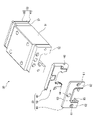
- FIG. 3 is an exploded perspective view of a lubricant supply member and a case of the lubrication unit shown in FIG. It is a side view for demonstrating the dimensional relationship between the concave part of the lubricant supply member accommodated in a case, and the cylindrical part of a case. It is a side view which shows the deformation state of the lubricant supply member by the reduction of the contained lubricant in the lubrication unit of 1st Embodiment.
- the vertical direction and the width direction of the slider represent the directions in the state of the slider assembled to the guide rail arranged horizontally in the longitudinal direction
- the width direction of the slider is the guide. It is a direction perpendicular to the longitudinal direction of the rail and the vertical direction of the slider, and is also called the horizontal direction (see FIG. 1).
- the longitudinal direction is also referred to as an axial direction.
- the linear guide 10 of the first embodiment is assembled so as to straddle the linear guide rail 20 and the guide rail 20, and is slidable via a plurality of rolling elements (balls) (not shown). It comprises a slider 30 that engages with.
- rail-side track surfaces 21 having a substantially semicircular cross section or a Gothic arch-shaped cross section are formed in the axial direction, and at the ridgeline portion where the upper surface 24 of the guide rail 20 and both side surfaces 23 intersect.
- a rail-side track surface 22 having a substantially 1/4 arc shape in cross section is formed in the axial direction.
- the slider 30 is attached to a slider main body 31, end caps 32 attached to both ends in the axial direction of the slider main body 31, and further axial ends of each end cap 32. It is composed of a lubrication unit 33 and.
- the slider main body 31 is formed in a substantially C shape, and has a slider-side raceway surface (not shown) facing the rail-side raceway surfaces 21 and 22 of the guide rail 20 on the inner side surfaces of both sleeves, and is a rolling element. It has a return route.
- the rail-side raceway surfaces 21 and 22 and the slider-side raceway surface guide the rolling element in a rolling manner and support a load acting on the slider 30 via the rolling element.
- the end cap 32 formed in a substantially C shape has a curved path (not shown) that communicates the slider side raceway surface of the slider main body 31 and the rolling element return path, and the rail side raceway surfaces 21, 22.
- a rolling element circulation path is formed by a slider-side track surface, a rolling element return path, and curved paths at both ends. A plurality of balls are tumblably loaded in the rolling element circulation path.
- the lubrication unit 33 includes a case 40 made of synthetic resin, a lubricant supply member 50 housed in the case 40, and a side seal 60.
- the side seal 60 is a substantially C-shaped steel plate that matches the outer shape of the end cap 32, and through holes 61 for mounting screws are formed in both sleeve portions 62 thereof, and both sleeve portions 62 are connected to each other.
- a through hole 64 for a grease nipple is formed in the connecting portion 63.
- the side seal 60 and the guide rail 20 are not in contact with each other, and the inside of the C-shaped portion is elastic such as nitrile rubber or polyurethane rubber containing grease in order to seal the gap between the slider 30 and the guide rail 20.
- a body 65 is provided.
- Grease for lubricating the rolling element and each raceway surface can be injected from the grease nipple into the inside of the rolling element circulation path, and in the initial state (the assembly completed state of the linear guide 10), the grease is applied to the rolling element circulation path. It is filled.
- the lubricant supply member 50 is formed in a substantially C shape so as to face both side surfaces 23 including the upper surface 24 of the guide rail 20 and the rail-side track surfaces 21 and 22. That is, the lubricant supply member 50 also has a pair of sleeve portions 58 formed at the left and right side surface positions of the guide rail 20 and a connecting portion 59 formed above the guide rail 20 to connect the pair of sleeve portions 58. , Equipped with.
- the lubricant supply member 50 is formed of a porous body such as rubber or synthetic resin, a fiber entanglement body, or the like, and is impregnated with the lubricant.
- the lubricant mineral oil, synthetic oil, grease and the like can be used.
- synthetic resin polyurethane, polyethylene, polypropylene and the like can be used.
- fiber entanglement body wool felt, polyester fiber, nylon fiber, acrylic fiber and the like can be used.
- the lubricant impregnation amount of the lubricant supply member 50 is preferably 70% by weight or more from the viewpoint of long-term use. Further, the upper limit of the lubricant impregnation amount is preferably 85% by weight or less in consideration of the strength of the lubricant supply member 50.
- the lubricant supply member 50 may be molded by mixing polyethylene and mineral oil with a weight ratio of 15:85.
- substantially semi-circular protrusions 51 for sliding contact with the rail-side raceway surface 21 of the guide rail 20 to supply the lubricant are provided on both inner side surfaces of the pair of sleeves 58 of the lubricant supply member 50.
- a recess 53 that opens upward is formed in substantially the center of the connecting portion 59 of the lubricant supply member 50.
- the recess 53 has two planes parallel to each other in the width direction and is formed in a substantially U shape.
- both outer surfaces of the pair of sleeve portions 58 of the lubricant supply member 50 extend in the vertical direction and are inward in the width direction from both outer surfaces of the connecting portion 59 so as not to interfere with the side wall 45 of the case 40 described later. positioned.
- chamfered portions 51a and 52a are formed at the end face edges of the protrusions 51 and 52 in the thickness direction, respectively.
- the slider 30 of the linear guide 10 may be removed from the guide rail 20 and reattached to the guide rail 20 during assembly work to the mechanical device.
- the end face edges of the protrusions 51 and 52 of the lubricant supply member 50 may interfere with the edges of the end faces of the rail-side raceway surfaces 21 and 22 of the guide rail 20, but the chamfered portions 51a and 52a may interfere with each other.
- the case 40 is manufactured by injection molding a hard resin such as polyacetal or polyamide, and is formed in a substantially C shape having substantially the same size as the end cap 32.
- the case 40 is a storage unit for accommodating the lubricant supply member 50 by the outer peripheral wall 41 covering the outer peripheral portion of the lubricant supply member 50 to be accommodated and the end wall 42 covering the axial end surface of the lubricant supply member 50. Forming 43.
- a cylindrical portion 44 which is an upper pressing means, is continuously formed on the outer peripheral wall 41 and the end wall 42 in the upper portion of the storage portion 43, substantially in the central portion in the left-right direction. Further, a pair of side walls 45 integrally formed with the outer peripheral wall 41 are continuously and symmetrically formed on the end wall 42 on both the left and right sides of the storage portion 43 facing the pair of sleeve portions 58. ing.
- the side wall 45 is provided with a screw insertion hole 47 for screwing and fixing the lubrication unit 33 to the slider main body 31.
- the case 40 may be manufactured by cutting or pressing a metal material such as steel or aluminum.
- a female screw portion 49 penetrating the side wall 45 in the width direction of the slider is formed on the side wall 45 of the case 40 at a position substantially equal to the protrusion 51.
- a screw member 70 that presses the sleeve portion 58 by protruding from the inner side surface in the width direction of the side wall 45 is inserted into the female screw portion 49.
- Each female threaded portion 49 and each threaded member 70 constitutes a pair of side surface pressing means.
- the cylindrical portion 44 of the case 40 is fitted into the recess 53 of the lubricant supply member 50, and the screw members 70 are brought into contact with the outer surfaces of the pair of sleeve portions 58, respectively, into the storage portion 43 of the case 40.
- the lubricant supply member 50 is housed.
- the case 40 can prevent the lubricant supply member 50 from being damaged during handling by accommodating the lubricant supply member 50.
- the lubricant impregnation amount of the lubricant supply member 50 is 70% by weight or more, the amount of resin is reduced by that amount and the strength of the lubricant supply member 50 is lowered, so that the case 40 is effective. ..
- the cylindrical portion 44 is press-fitted into the concave portion 53 with a tightening allowance in the width direction. ..
- a pressing force in the direction of widening the inner width of the recess 53 acts on the recess 53, and as a result, the central portion of the lubricant supply member 50 (connecting portion 59) in the left-right direction is deformed so as to be convex upward.
- the left and right sleeve portions 58 are also deformed so as to approach each other in the left-right direction.
- the screw member 70 presses the outer surfaces of the left and right sleeve portions 58, the left and right sleeve portions 58 are deformed so as to approach each other in the left-right direction.
- the cylindrical portion 44 exerts a pressing force in the width direction on the recess 53, but is allowed to move in the vertical direction and is not restrained. Therefore, the connecting portion 59 (lubricant supply member 50) can be slightly moved in the vertical direction in the accommodating portion 43 of the case 40. Further, in the present embodiment, since the cylindrical portion 44 is continuously provided with the outer peripheral wall 41 of the case 40, the outer diameter D of the cylindrical portion 44 is given by the arcuate surfaces facing each other.
- the lubricant is reliably supplied to the rail-side raceway surfaces 21 and 22 by the protrusions 51 and 52 of the lubricant supply member 50.
- the pressing force of the protrusions 51 and 52 with respect to the rail-side raceway surfaces 21 and 22 is adjusted by the dimensions of the recess 53 and the cylindrical portion 44 and the protrusion amount of the screw member 70.
- the lower surface of the cylindrical cylindrical portion 44 is cut out in the horizontal direction, and the flat surface portion 48 is provided.
- the linear guide 10 configured in this way, when the slider 30 moves on the guide rail 20, the ball in the slider 30 repeatedly circulates in the rolling element circulation path. At this time, the protrusions 51 and 52 of the lubricant supply member 50 are in sliding contact with a part of the rail-side raceway surfaces 21 and 22 of the guide rail 20, and the lubricant impregnated by the lubricant supply member 50 seeps out to the rail. It is automatically supplied to the side track surfaces 21, 22 and the ball. As a result, even when the grease previously filled in the rolling element circulation path is reduced, the linear guide 10 maintains a good lubrication state, and the linear guide 10 is stably and smoothly operated for a long period of time.
- the linear guide 10 when used for a long period of time, the amount of lubricant impregnated in the lubricant supply member 50 decreases, and as shown in FIG. 6, the dimensions of the lubricant supply member 50 are shown by broken lines in the figure. From the state, it becomes almost evenly smaller as shown by the solid line in the figure.
- the lubricant supply member 50 can be surely brought into contact with the guide rail 20 for a long period of time. It is possible to maintain a good lubrication state. Further, even if the lubrication state is poor and the lubricant supply member 50 at the rail contact point is worn more than expected, the pressing force by the screw member 70 can be adjusted, so that the lubricant supply member 50 can be used on the rail raceway surface 21. It can be reliably contacted with 22.
- the lubricant supply member 50 can be displaced relative to the case 40 in the vertical direction, the lubricant supply member 50 absorbs the vertical assembly error between the guide rail 20 and the slider 30 at the time of assembling the linear guide 10 for lubrication.
- the agent supply member 50 can be reliably brought into contact with the rail raceway surfaces 21 and 22. Further, even when the lubricant supply member 50 shrinks slightly due to long-term use, the lubricant supply member 50 moves to the optimum vertical position with respect to the guide rail 20, so that the rail raceway surfaces 21 and 22 are formed. The contact state of can be stably maintained.
- the screw member 70 protrudes in advance from the inner side surface in the width direction of the side wall 45 to press the sleeve portion 58, but in the initial state in which the lubricant supply member 50 is incorporated in the case 40, the screw member The side wall 45 of the case 40 may press the sleeve portion 58 at a position where the 70 is retracted from the inner side surface in the width direction of the side wall 45.
- the screw member 70 is tightened so that the lubricant supply member 50 is surely brought into contact with the guide rail 20 for a long period of time. Good lubrication can be maintained throughout.
- FIG. 7 is a side view showing the lubricant supply member and the case of the lubrication unit of the second embodiment together with the deformed state of the lubricant supply member.
- the side seal 60 has the same configuration as that of the first embodiment, and thus the description thereof is omitted.
- a resin ball 80 as an elastic member is provided on the side wall 45 of the case 40a instead of the screw member 70 advancing and retreating from the female screw portion 49 of the first embodiment. is set up.
- the resin ball 80 is formed so as to project from the recesses 46 formed on both inner side surfaces of the side wall 45 and press the outer surface of the sleeve portion 58.
- the resin ball 80 can press the outer surface of the sleeve portion 58 to ensure that the lubricant supply member 50 is in contact with the guide rail 20 for a long period of time. It is possible to maintain a good lubrication state. Further, even if the lubrication state is poor and the lubricant supply member 50 at the rail contact point is worn more than expected, the resin ball 80 can automatically adjust the pressing force, so that the lubricant supply member 50 is placed on the rail raceway surface. It can be reliably contacted.
- a member other than the resin ball may be installed as the elastic member as long as it presses the sleeve portion 58.
- Other configurations and operations are the same as those of the first embodiment.
- the present invention is not limited to the above-described embodiments, and can be appropriately modified, improved, and the like.
- the lubrication unit of the above embodiment has a configuration having an upper pressing means and a pair of side pressing means, but the lubrication unit of the present invention is not limited to this, and the pair of side pressing means is not provided. It may be configured to have only means. Further, as the rolling element, a roller may be used instead of the ball.
Landscapes
- Engineering & Computer Science (AREA)
- General Engineering & Computer Science (AREA)
- Mechanical Engineering (AREA)
- Bearings For Parts Moving Linearly (AREA)
- Rolling Contact Bearings (AREA)
Abstract
潤滑ユニットが長期間に亘って安定して潤滑剤を供給することができるリニアガイドを提供する。潤滑剤供給部材は、案内レールの左右両側面位置に形成された一対の袖部と、該一対の袖部を連結する連結部と、を備えて略C字状に形成され、一対の袖部は、案内レールのレール側軌道面に摺接可能な突部を有する。潤滑ユニットは、一対の袖部に対してスライダの幅方向外側に設けられたケースの側壁に取り付けられ、一対の袖部をスライダの幅方向内方にそれぞれ押圧する一対の側面押圧手段を備える。
Description
本発明は、リニアガイドに関し、より詳細には、長期間に亘って潤滑剤を案内レール、スライダ、及び転動体の接触部に供給することができるリニアガイドに関する。
従来、リニアガイドは、軸方向に延びる案内レールと、案内レールに相対移動可能に跨架されたスライダと、を備え、案内レール及びスライダに形成された転動体転動溝間を循環する複数の転動体(ボール)を介して、スライダが案内レール上を軸方向に相対移動する。このようなリニアガイドは、各種生産設備の直線移動機構に多用されている。このリニアガイドを、長期間に亘って安定して使用するためには、転動体転動溝及びボールに十分な量の潤滑剤を供給して、潤滑状態を良好に維持することが重要である。
特許文献1には、潤滑剤を含有する多孔質の潤滑剤供給部材をケース内に収容してスライダの端部に取り付け、案内レールの転動体転動溝に接触する潤滑剤供給部材から潤滑剤を供給するようにした直動案内軸受装置が記載されている。
また、特許文献2では、エンドキャップの外側面に、エンドキャップに近い側から、補強板、潤滑剤含有部材及びサイドシールが重ね合わせた状態で固定されている。潤滑剤含有部材は、エンドキャップに合わせたC字形状に形成されていて、その連結部に上部を開放して形成された貫通孔に、その内径よりも外径が大きいリング状部材を嵌め込むことにより、貫通孔が押し広げられ、両袖部を案内レールに押しつけている。また、両袖部の外側面側を開放した貫通孔にもそれぞれ、リング状部材が嵌め込まれている。
また、特許文献2では、エンドキャップの外側面に、エンドキャップに近い側から、補強板、潤滑剤含有部材及びサイドシールが重ね合わせた状態で固定されている。潤滑剤含有部材は、エンドキャップに合わせたC字形状に形成されていて、その連結部に上部を開放して形成された貫通孔に、その内径よりも外径が大きいリング状部材を嵌め込むことにより、貫通孔が押し広げられ、両袖部を案内レールに押しつけている。また、両袖部の外側面側を開放した貫通孔にもそれぞれ、リング状部材が嵌め込まれている。
ところで、特許文献1の潤滑ユニット100では、図8に示すように、潤滑剤を含有する潤滑剤供給部材101は、円筒部104が一体に形成されたケース103に収納されている。また、潤滑剤供給部材101は、上部に形成された凹部102にケース103の円筒部104が嵌め込まれて、潤滑剤供給部材101の上端部をスライダの幅方向外方に押圧変形させると共に、潤滑剤供給部材101の摺動部105の裏面が、ケース103の両側面に設けられた押圧部106で押圧されて、案内レール107の転動体転動溝108に押し付けられて、潤滑剤を供給するようになっている。
しかしながら、長期間の使用に伴って潤滑剤供給部材101に含浸した潤滑剤量が減ると、潤滑剤供給部材101が、案内レール107に向かって小さくなり(収縮して)、円筒部104及び押圧部106による押圧力が低下し、潤滑剤供給部材101と案内レール107の転動体転動溝108との接触状態が変化して十分な潤滑状態を保てなくなる虞がある。特に、潤滑剤供給部材101の潤滑剤含有量が非常に多いと、潤滑剤の減少による潤滑剤供給部材101の寸法変化が大きく、上記した不具合が生じる可能性が高くなる。
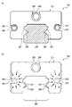
また、図9(a)に示すように、特許文献2に記載の潤滑ユニット200では、潤滑剤供給部材201は、上部に形成された略U字形の上溝202と、両側面に形成された略U字形の一対の横溝203と、案内レール206の転動体転動溝207に摺接する摺動部208と、を備える。上溝202には、上部リング204が設置され、一対の横溝203には、それぞれ側面リング205が設置され、側面リング205には、不図示のサイドシール及び潤滑ユニット200をスライダに固定するための不図示のねじが挿通されている。このため、側面リング205と案内レール206との相対位置は、不図示の転動体を介して固定となる。
この場合も、図9(b)に示すように、長期間の使用により潤滑剤供給部材201に含浸した潤滑剤量が低減すると、潤滑剤供給部材201の寸法が、図中破線で示す状態から図中実線で示すように小さくなる。その際、側面リング205の位置が固定されているため、潤滑剤供給部材201は、側面リング205に向かって矢印方向に変形する。この結果、潤滑剤供給部材201の摺動部208と案内レール206の転動体転動溝207との接触状態が変化して十分な潤滑状態を保てなくなる虞がある。
本発明は、前述した課題に鑑みてなされたものであり、その目的は、潤滑ユニットが長期間に亘って安定して潤滑剤を供給することができるリニアガイドを提供することにある。
本発明の上記目的は、下記の構成により達成される。
(1) 案内レールと、
該案内レールを跨ぐようにスライド自在に係合するスライダと、
潤滑剤を含浸可能な潤滑剤供給部材と、該潤滑剤供給部材を収容するケースと、を有し、前記スライダの軸方向の端部に取り付けられた潤滑ユニットと、を備えるリニアガイドであって、
前記潤滑剤供給部材は、前記案内レールの左右両側面位置に形成された一対の袖部と、該一対の袖部を連結する連結部と、を備えて略C字状に形成され、前記一対の袖部は、前記案内レールのレール側軌道面に摺接可能な突部を有し、
前記潤滑ユニットは、前記一対の袖部に対して前記スライダの幅方向外側に設けられた前記ケースの側壁に取り付けられ、前記一対の袖部を前記スライダの幅方向内方にそれぞれ押圧する一対の側面押圧手段を備えることを特徴とするリニアガイド。
(2) 前記各側面押圧手段は、前記ケースの側壁に形成され、前記スライダの幅方向に貫通する雌ねじ部と、該雌ねじ部に挿入されて、該側壁の幅方向内側面から突出することで前記袖部を押圧するねじ部材と、を有することを特徴とする(1)に記載のリニアガイド。
(3) 前記各側面押圧手段は、前記ケースの側壁の幅方向内側面に配置され、前記袖部を押圧する弾性部材であることを特徴とする(1)に記載のリニアガイド。
(4) 前記潤滑剤供給部材は、前記案内レールの上方位置に形成された凹部を有し、
前記潤滑ユニットは、前記連結部の前記スライダの上下方向への移動を許容し、前記凹部を前記スライダの幅方向外方に押圧するように、前記凹部内に配置される上部押圧手段を備えることを特徴とする(1)~(3)のいずれかに記載のリニアガイド。
(5) 前記突部は、前記スライダの長手方向の端面縁部に面取りが形成されていることを特徴とする(1)~(4)のいずれかに記載のリニアガイド。
(1) 案内レールと、
該案内レールを跨ぐようにスライド自在に係合するスライダと、
潤滑剤を含浸可能な潤滑剤供給部材と、該潤滑剤供給部材を収容するケースと、を有し、前記スライダの軸方向の端部に取り付けられた潤滑ユニットと、を備えるリニアガイドであって、
前記潤滑剤供給部材は、前記案内レールの左右両側面位置に形成された一対の袖部と、該一対の袖部を連結する連結部と、を備えて略C字状に形成され、前記一対の袖部は、前記案内レールのレール側軌道面に摺接可能な突部を有し、
前記潤滑ユニットは、前記一対の袖部に対して前記スライダの幅方向外側に設けられた前記ケースの側壁に取り付けられ、前記一対の袖部を前記スライダの幅方向内方にそれぞれ押圧する一対の側面押圧手段を備えることを特徴とするリニアガイド。
(2) 前記各側面押圧手段は、前記ケースの側壁に形成され、前記スライダの幅方向に貫通する雌ねじ部と、該雌ねじ部に挿入されて、該側壁の幅方向内側面から突出することで前記袖部を押圧するねじ部材と、を有することを特徴とする(1)に記載のリニアガイド。
(3) 前記各側面押圧手段は、前記ケースの側壁の幅方向内側面に配置され、前記袖部を押圧する弾性部材であることを特徴とする(1)に記載のリニアガイド。
(4) 前記潤滑剤供給部材は、前記案内レールの上方位置に形成された凹部を有し、
前記潤滑ユニットは、前記連結部の前記スライダの上下方向への移動を許容し、前記凹部を前記スライダの幅方向外方に押圧するように、前記凹部内に配置される上部押圧手段を備えることを特徴とする(1)~(3)のいずれかに記載のリニアガイド。
(5) 前記突部は、前記スライダの長手方向の端面縁部に面取りが形成されていることを特徴とする(1)~(4)のいずれかに記載のリニアガイド。
本発明のリニアガイドによれば、長期間の使用に伴って含浸した潤滑剤量が少なくなり、潤滑剤供給部材の寸法が小さくなっても、一対の側面押圧手段により、潤滑剤供給部材の一対の袖部がスライダの幅方向内方にそれぞれ押圧されているので、潤滑剤供給部材の突部がレール側軌道面を押し付ける力が確保される。したがって、潤滑ユニットが長期間に亘って安定して潤滑剤を供給することができる。
以下、本発明の各実施形態に係るリニアガイドを図面に基づいて詳細に説明する。なお、以下の説明において、スライダの上下方向、幅方向とは、長手方向を水平にして配置された案内レールに組み付けられたスライダの状態における方向をそれぞれ表しており、スライダの幅方向は、案内レールの長手方向及びスライダの上下方向に垂直な方向であり、左右方向とも言う(図1参照)。また、長手方向は、軸方向とも言う。
(第1実施形態)
図1に示すように、第1実施形態のリニアガイド10は、直線状の案内レール20と、案内レール20を跨ぐように組み付けられ、不図示の複数の転動体(ボール)を介してスライド自在に係合するスライダ30と、を備えている。
図1に示すように、第1実施形態のリニアガイド10は、直線状の案内レール20と、案内レール20を跨ぐように組み付けられ、不図示の複数の転動体(ボール)を介してスライド自在に係合するスライダ30と、を備えている。
案内レール20の両側面23には、断面略半円形または断面ゴシックアーチ形状のレール側軌道面21が軸方向に形成され、案内レール20の上面24と両側面23とが交差する稜線部には、断面略1/4円弧状のレール側軌道面22が軸方向に形成されている。
スライダ30は、図2及び図3に示すように、スライダ本体31と、スライダ本体31の軸方向両端部に取り付けられたエンドキャップ32と、各エンドキャップ32の更に軸方向端部に取り付けられた潤滑ユニット33と、からなる。
スライダ本体31は、略C字状に形成されており、両袖部の内側面に、案内レール20のレール側軌道面21、22に対向する不図示のスライダ側軌道面を有するとともに、転動体戻し路を有している。レール側軌道面21、22及びスライダ側軌道面は、転動体を転動自在に案内すると共に、転動体を介してスライダ30に作用する荷重を支持している。また、略C字状に形成されたエンドキャップ32は、スライダ本体31のスライダ側軌道面及び転動体戻し路を連通させる不図示の湾曲路を有しており、レール側軌道面21、22、スライダ側軌道面、転動体戻し路、及び両端部の湾曲路で、転動体循環路を形成している。転動体循環路内には、複数のボールが転動自在に装填されている。
図3及び図4を参照して、潤滑ユニット33は、合成樹脂製のケース40と、ケース40内に収容される潤滑剤供給部材50と、サイドシール60と、を備える。
サイドシール60は、エンドキャップ32の外形に合わせた略C字形状の鋼板であり、その両袖部62には、取付ネジ用の貫通孔61が形成されるとともに、それら両袖部62を連結する連結部63には、グリースニップル用の貫通孔64が形成されている。サイドシール60と案内レール20とは非接触であり、C字部の内側には、スライダ30と案内レール20との間の隙間をシールするため、ニトリルゴムやグリースを含有したポリウレタンゴムなどの弾性体65が設けられている。
転動体及び各軌道面を潤滑するためのグリースが、グリースニップルから転動体循環路の内部に注入可能であり、初期状態(リニアガイド10の組立完了状態)において、転動体循環路にはグリースが充填されている。
転動体及び各軌道面を潤滑するためのグリースが、グリースニップルから転動体循環路の内部に注入可能であり、初期状態(リニアガイド10の組立完了状態)において、転動体循環路にはグリースが充填されている。
潤滑剤供給部材50は、案内レール20の上面24及びレール側軌道面21、22を含む両側面23に対向するように、略C字状に成形される。即ち、潤滑剤供給部材50も、案内レール20の左右両側面位置に形成された一対の袖部58と、案内レール20の上方位置に形成されて一対の袖部58を連結する連結部59と、を備える。潤滑剤供給部材50は、ゴムや合成樹脂等の多孔質体、繊維交絡体などで形成されて、潤滑剤を含浸する。潤滑剤としては、鉱油、合成油、グリースなどを用いることができる。合成樹脂としては、ポリウレタン、ポリエチレン、ポリプロピレンなどを用いることができる。繊維交絡体としては、羊毛フェルト、ポリエステル繊維、ナイロン繊維、アクリル繊維などを用いることができる。
潤滑剤供給部材50の潤滑剤含浸量は、長期間の使用の観点から、70重量%以上であることが好ましい。また、潤滑剤含浸量の上限は、潤滑剤供給部材50の強度を考慮して85重量%以下であることが好ましい。例えば、本実施形態の一例として、潤滑剤供給部材50は、重量比率を15:85とする、ポリエチレンと鉱油とを混合して成形したものが挙げられる。
潤滑剤供給部材50の一対の袖部58の両内側面には、案内レール20のレール側軌道面21に摺接して潤滑剤を供給するための略半円形の突部51が突設されている。また、一対の袖部58と連結部59との内隅部には、案内レール20のレール側軌道面22に摺接して潤滑剤を供給するための1/4円弧状の突部52が突設されている。
さらに、潤滑剤供給部材50の連結部59の略中央には、上方に開放する凹部53が形成されている。凹部53は、幅方向に対向する互いに平行な2つの平面を持って略Uの字形に形成される。また、潤滑剤供給部材50の一対の袖部58の両外側面は、上下方向に延び、後述するケース40の側壁45と干渉しないように、連結部59の両外側面よりも幅方向内側に位置している。
なお、図4に示すように、突部51、52の厚み方向の端面縁部には、それぞれ面取り部51a,52aが形成されている。リニアガイド10のスライダ30は、機械装置への組付け作業の際に、案内レール20から取り外され、再度、案内レール20に取付ける場合がある。その際、潤滑剤供給部材50の突部51、52の端面縁部が、案内レール20のレール側軌道面21,22の端面のエッジと干渉する可能性があるが、上記面取り部51a,52aを設けることで、上記干渉が防止されて、組付け作業性を向上することができる。
ケース40は、ポリアセタールやポリアミドなどの硬質樹脂を射出成形して製作されており、エンドキャップ32と略同一サイズの略C字状に形成されている。ケース40は、収容される潤滑剤供給部材50の外周部を覆う外周壁41と、潤滑剤供給部材50の軸方向端面を覆う端壁42とによって潤滑剤供給部材50を収納するための収納部43を形成している。
収納部43内の上部で、左右方向略中央部には、上部押圧手段である円筒部44が、外周壁41及び端壁42に連続して形成されている。また、収納部43内の左右両側で、一対の袖部58と対向する部分には、外周壁41と一体に形成される一対の側壁45が、端壁42に連続して左右対称に形成されている。側壁45には、潤滑ユニット33をスライダ本体31にねじ固定するためのねじ挿通孔47が設けられている。
なお、ケース40は、鋼、アルミニウムなどの金属材料を、切削加工やプレス加工して製作したものであってもよい。
なお、ケース40は、鋼、アルミニウムなどの金属材料を、切削加工やプレス加工して製作したものであってもよい。
さらに、図5にも示すように、ケース40の側壁45には、突部51と略等しい高さ位置に、スライダの幅方向に側壁45を貫通する雌ねじ部49が形成される。該雌ねじ部49には、側壁45の幅方向内側面から突出することで袖部58を押圧するねじ部材70が挿入される。各雌ねじ部49及び各ねじ部材70は、一対の側面押圧手段を構成する。
そして、潤滑剤供給部材50の凹部53にケース40の円筒部44を嵌め込むと共に、一対の袖部58の外側面に、それぞれねじ部材70を当接させて、ケース40の収納部43内に潤滑剤供給部材50を収納する。
このように、ケース40は、潤滑剤供給部材50を収納することで、取り扱い中に、潤滑剤供給部材50が損傷するのを防止できる。特に、潤滑剤供給部材50の潤滑剤含浸量が70重量%以上になると、その分、樹脂の量が少なくなり、潤滑剤供給部材50の強度が低下するため、ケース40の使用は有効である。
また、円筒部44の外径Dは、凹部53の内幅(左右幅)D1より大きく設定されているので、円筒部44は、幅方向の締め代を有した状態で凹部53に圧入される。これにより、凹部53には、凹部53の内幅を広げる方向の押圧力が作用し、この結果、潤滑剤供給部材50(連結部59)の左右方向中央部が上に凸となるように変形し、それに伴って、左右の袖部58も互いに左右方向に近づくように変形する。
また、ねじ部材70が、左右の袖部58の外側面を押圧しているため、左右の袖部58が、互いに左右方向に近づくように変形する。
また、ねじ部材70が、左右の袖部58の外側面を押圧しているため、左右の袖部58が、互いに左右方向に近づくように変形する。
なお、円筒部44は、凹部53に対して幅方向の押圧力を作用させるが、上下方向への移動は許容され、拘束されない。従って、連結部59(潤滑剤供給部材50)は、ケース40の収納部43内において、若干の上下方向の移動が可能である。
また、本実施形態では、円筒部44は、ケース40の外周壁41と連続して設けられているため、円筒部44の外径Dは、それぞれ対向する円弧面によって与えられるものとする。
また、本実施形態では、円筒部44は、ケース40の外周壁41と連続して設けられているため、円筒部44の外径Dは、それぞれ対向する円弧面によって与えられるものとする。
従って、潤滑剤供給部材50の突部51,52により、レール側軌道面21,22へ潤滑剤が確実に供給される。レール側軌道面21,22に対する突部51,52の押圧力は、凹部53と、円筒部44の寸法、およびねじ部材70の突出量で調整される。
また、本実施形態のケース40は、円筒形の円筒部44の下面が水平方向に切り欠かれて、平面部48が設けられている。これにより、案内レール20の上面24と円筒部44の下面である平面部48との間の距離が大きくなり、上面24と平面部48との間に配置される潤滑剤供給部材50の幅Sを広くすることができ、潤滑剤供給部材50の強度が向上する。また、潤滑剤の含有量を多くしても、潤滑剤供給部材50の変形や破断の虞が低減し、取り扱いが容易になる。
このように構成されたリニアガイド10では、案内レール20上をスライダ30が移動すると、スライダ30内のボールは、転動体循環路内を繰り返し循環移動する。このとき、潤滑剤供給部材50の突部51,52は、案内レール20のレール側軌道面21,22の一部と摺接し、潤滑剤供給部材50が含浸する潤滑剤が滲み出して、レール側軌道面21、22及びボールに自動的に供給される。これにより、転動体循環路の内部に予め充填されていたグリースが減少した場合でも、良好な潤滑状態を維持して、リニアガイド10は、長期間に亘って安定した滑らかな作動が行われる。
また、リニアガイド10が長期間使用されると、潤滑剤供給部材50に含浸されている潤滑剤が減少し、図6に示すように、潤滑剤供給部材50の寸法が、図中破線で示す状態から図中実線で示すようにほぼ均等に小さくなる。
しかしながら、潤滑剤供給部材50の寸法が小さくなっても、ねじ部材70を雌ねじ部49に締め込むことにより、潤滑剤供給部材50を確実に案内レール20に接触させることができ、長期間に亘って良好な潤滑状態を保つことができる。
また、潤滑状態が悪く、レール接触箇所の潤滑剤供給部材50が想定以上に摩耗した場合でも、ねじ部材70による押圧力を調整することができるため、潤滑剤供給部材50をレール軌道面21,22に確実に接触させることができる。
また、潤滑剤供給部材50はケース40に対して上下方向の相対変位が可能であるので、リニアガイド10の組立時における案内レール20とスライダ30との上下方向の組立誤差を吸収して、潤滑剤供給部材50をレール軌道面21,22に確実に接触させることができる。さらに、長期間の使用により潤滑剤供給部材50が小さく収縮した場合でも、潤滑剤供給部材50は、案内レール20に対して最適となる上下位置に移動することにより、レール軌道面21,22との接触状態を安定して維持することができる。
また、潤滑状態が悪く、レール接触箇所の潤滑剤供給部材50が想定以上に摩耗した場合でも、ねじ部材70による押圧力を調整することができるため、潤滑剤供給部材50をレール軌道面21,22に確実に接触させることができる。
また、潤滑剤供給部材50はケース40に対して上下方向の相対変位が可能であるので、リニアガイド10の組立時における案内レール20とスライダ30との上下方向の組立誤差を吸収して、潤滑剤供給部材50をレール軌道面21,22に確実に接触させることができる。さらに、長期間の使用により潤滑剤供給部材50が小さく収縮した場合でも、潤滑剤供給部材50は、案内レール20に対して最適となる上下位置に移動することにより、レール軌道面21,22との接触状態を安定して維持することができる。
なお、本実施形態では、ねじ部材70が側壁45の幅方向内側面から予め突出して、袖部58を押圧しているが、潤滑剤供給部材50をケース40に組み込んだ初期状態では、ねじ部材70が側壁45の幅方向内側面から退避した位置とし、ケース40の側壁45が、袖部58を押圧するようにしてもよい。そして、長期間の使用により潤滑剤供給部材50の寸法が小さくなった場合には、ねじ部材70を締め込むことにより、潤滑剤供給部材50を確実に案内レール20に接触させて、長期間に亘って良好な潤滑状態を保つことができる。
(第2実施形態)
図7は、第2実施形態の潤滑ユニットの潤滑剤供給部材及びケースを潤滑剤供給部材の変形状態とともに示す側面図である。なお、本実施形態の潤滑ユニット33Aのうち、サイドシール60は、第1実施形態のものと同様の構成であるので、説明を省略している。
図7は、第2実施形態の潤滑ユニットの潤滑剤供給部材及びケースを潤滑剤供給部材の変形状態とともに示す側面図である。なお、本実施形態の潤滑ユニット33Aのうち、サイドシール60は、第1実施形態のものと同様の構成であるので、説明を省略している。
第2実施形態の潤滑ユニット33Aでは、一対の側面押圧手段として、第1実施形態の雌ねじ部49から進退するねじ部材70の代わりに、ケース40aの側壁45に、弾性部材としての樹脂ボール80が設置されている。樹脂ボール80は、側壁45の両内側面に形成された凹部46から突出して、袖部58の外側面を押圧するように形成される。
したがって、本実施形態においても、リニアガイド10が長期間使用されると、潤滑剤供給部材50に含浸されている潤滑剤が減少し、図7に示すように、潤滑剤供給部材50の寸法が、図中破線で示す状態から図中実線で示すようにほぼ均等に小さくなる。
しかしながら、潤滑剤供給部材50の寸法が小さくなっても、樹脂ボール80が袖部58の外側面を押圧して、潤滑剤供給部材50を確実に案内レール20に接触させることができ、長期間に亘って良好な潤滑状態を保つことができる。
また、潤滑状態が悪く、レール接触箇所の潤滑剤供給部材50が想定以上に摩耗した場合でも、樹脂ボール80が押圧力を自動調整することができるため、潤滑剤供給部材50をレール軌道面に確実に接触させることができる。
なお、本実施形態では、弾性部材は、潤滑剤供給部材50の寸法が小さくなっても、袖部58を押圧するものであれば、樹脂ボール以外のものが設置されてもよい。
その他の構成及び作用については、第1実施形態のものと同様である。
また、潤滑状態が悪く、レール接触箇所の潤滑剤供給部材50が想定以上に摩耗した場合でも、樹脂ボール80が押圧力を自動調整することができるため、潤滑剤供給部材50をレール軌道面に確実に接触させることができる。
なお、本実施形態では、弾性部材は、潤滑剤供給部材50の寸法が小さくなっても、袖部58を押圧するものであれば、樹脂ボール以外のものが設置されてもよい。
その他の構成及び作用については、第1実施形態のものと同様である。
尚、本発明は、前述した各実施形態に限定されるものではなく、適宜、変形、改良、等が可能である。
例えば、上記実施形態の潤滑ユニットは、上部押圧手段と一対の側面押圧手段を有する構成であるが、本発明の潤滑ユニットは、これに限らず、上部押圧手段を設けずに、一対の側面押圧手段のみを有する構成であってもよい。
また、転動体としては、ボールの代わりにローラ(ころ)を使用してもよい。
例えば、上記実施形態の潤滑ユニットは、上部押圧手段と一対の側面押圧手段を有する構成であるが、本発明の潤滑ユニットは、これに限らず、上部押圧手段を設けずに、一対の側面押圧手段のみを有する構成であってもよい。
また、転動体としては、ボールの代わりにローラ(ころ)を使用してもよい。
なお、本出願は、2020年11月16日出願の日本特許出願(特願2020-190343)に基づくものであり、その内容は本出願の中に参照として援用される。
10 リニアガイド
20 案内レール
21,22 レール側軌道面
30 スライダ
33,33A 潤滑ユニット
40 ケース
44 円筒部(上部押圧手段)
45 側壁
49 雌ねじ部
50 潤滑剤供給部材
51,52 突部
53 凹部
58 袖部
59 連結部
70 ねじ部材(側面押圧手段)
D 外径
D1 内幅
20 案内レール
21,22 レール側軌道面
30 スライダ
33,33A 潤滑ユニット
40 ケース
44 円筒部(上部押圧手段)
45 側壁
49 雌ねじ部
50 潤滑剤供給部材
51,52 突部
53 凹部
58 袖部
59 連結部
70 ねじ部材(側面押圧手段)
D 外径
D1 内幅
Claims (5)
- 案内レールと、
該案内レールを跨ぐようにスライド自在に係合するスライダと、
潤滑剤を含浸可能な潤滑剤供給部材と、該潤滑剤供給部材を収容するケースと、を有し、前記スライダの軸方向の端部に取り付けられた潤滑ユニットと、を備えるリニアガイドであって、
前記潤滑剤供給部材は、前記案内レールの左右両側面位置に形成された一対の袖部と、該一対の袖部を連結する連結部と、を備えて略C字状に形成され、前記一対の袖部は、前記案内レールのレール側軌道面に摺接可能な突部を有し、
前記潤滑ユニットは、前記一対の袖部に対して前記スライダの幅方向外側に設けられた前記ケースの側壁に取り付けられ、前記一対の袖部を前記スライダの幅方向内方にそれぞれ押圧する一対の側面押圧手段を備えることを特徴とするリニアガイド。 - 前記各側面押圧手段は、前記ケースの側壁に形成され、前記スライダの幅方向に貫通する雌ねじ部と、該雌ねじ部に挿入されて、該側壁の幅方向内側面から突出することで前記袖部を押圧するねじ部材と、を有することを特徴とする請求項1に記載のリニアガイド。
- 前記各側面押圧手段は、前記ケースの側壁の幅方向内側面に配置され、前記袖部を押圧する弾性部材であることを特徴とする請求項1に記載のリニアガイド。
- 前記潤滑剤供給部材は、前記案内レールの上方位置に形成された凹部を有し、
前記潤滑ユニットは、前記連結部の前記スライダの上下方向への移動を許容し、前記凹部を前記スライダの幅方向外方に押圧するように、前記凹部内に配置される上部押圧手段を備えることを特徴とする請求項1~3のいずれか1項に記載のリニアガイド。 - 前記突部は、前記スライダの長手方向の端面縁部に面取りが形成されていることを特徴とする請求項1~4のいずれか1項に記載のリニアガイド。
Priority Applications (2)
| Application Number | Priority Date | Filing Date | Title |
|---|---|---|---|
| KR1020237015160A KR102880479B1 (ko) | 2020-11-16 | 2021-10-27 | 리니어 가이드 |
| CN202180076392.8A CN116438385A (zh) | 2020-11-16 | 2021-10-27 | 线性引导件 |
Applications Claiming Priority (2)
| Application Number | Priority Date | Filing Date | Title |
|---|---|---|---|
| JP2020190343A JP7725814B2 (ja) | 2020-11-16 | 2020-11-16 | リニアガイド |
| JP2020-190343 | 2020-11-16 |
Publications (1)
| Publication Number | Publication Date |
|---|---|
| WO2022102413A1 true WO2022102413A1 (ja) | 2022-05-19 |
Family
ID=81601063
Family Applications (1)
| Application Number | Title | Priority Date | Filing Date |
|---|---|---|---|
| PCT/JP2021/039723 Ceased WO2022102413A1 (ja) | 2020-11-16 | 2021-10-27 | リニアガイド |
Country Status (4)
| Country | Link |
|---|---|
| JP (1) | JP7725814B2 (ja) |
| KR (1) | KR102880479B1 (ja) |
| CN (1) | CN116438385A (ja) |
| WO (1) | WO2022102413A1 (ja) |
Families Citing this family (1)
| Publication number | Priority date | Publication date | Assignee | Title |
|---|---|---|---|---|
| TWI912717B (zh) * | 2024-03-08 | 2026-01-21 | 銀泰科技股份有限公司 | 線性滑軌的導向潤滑結構 |
Citations (5)
| Publication number | Priority date | Publication date | Assignee | Title |
|---|---|---|---|---|
| JPH0458620U (ja) * | 1990-09-27 | 1992-05-20 | ||
| JPH1193951A (ja) * | 1997-09-22 | 1999-04-06 | Shirota Seisakusho:Kk | ウッドセラミックス又はその他の植物性セラミックスを摩 擦体とする無潤滑摺動形ブッシュ装置 |
| JP2006046529A (ja) * | 2004-08-05 | 2006-02-16 | Nsk Ltd | 直動案内軸受装置 |
| WO2017026788A1 (ko) * | 2015-08-10 | 2017-02-16 | 티에치케이 가부시끼가이샤 | 고체윤활씰 자동 위치보정장치 |
| JP2018040389A (ja) * | 2016-09-05 | 2018-03-15 | 日本精工株式会社 | リニアガイド |
Family Cites Families (1)
| Publication number | Priority date | Publication date | Assignee | Title |
|---|---|---|---|---|
| JP3365170B2 (ja) | 1995-10-13 | 2003-01-08 | 日本精工株式会社 | 直動案内軸受装置 |
-
2020
- 2020-11-16 JP JP2020190343A patent/JP7725814B2/ja active Active
-
2021
- 2021-10-27 WO PCT/JP2021/039723 patent/WO2022102413A1/ja not_active Ceased
- 2021-10-27 CN CN202180076392.8A patent/CN116438385A/zh active Pending
- 2021-10-27 KR KR1020237015160A patent/KR102880479B1/ko active Active
Patent Citations (5)
| Publication number | Priority date | Publication date | Assignee | Title |
|---|---|---|---|---|
| JPH0458620U (ja) * | 1990-09-27 | 1992-05-20 | ||
| JPH1193951A (ja) * | 1997-09-22 | 1999-04-06 | Shirota Seisakusho:Kk | ウッドセラミックス又はその他の植物性セラミックスを摩 擦体とする無潤滑摺動形ブッシュ装置 |
| JP2006046529A (ja) * | 2004-08-05 | 2006-02-16 | Nsk Ltd | 直動案内軸受装置 |
| WO2017026788A1 (ko) * | 2015-08-10 | 2017-02-16 | 티에치케이 가부시끼가이샤 | 고체윤활씰 자동 위치보정장치 |
| JP2018040389A (ja) * | 2016-09-05 | 2018-03-15 | 日本精工株式会社 | リニアガイド |
Also Published As
| Publication number | Publication date |
|---|---|
| KR20230082040A (ko) | 2023-06-08 |
| KR102880479B1 (ko) | 2025-11-03 |
| JP2022079259A (ja) | 2022-05-26 |
| CN116438385A (zh) | 2023-07-14 |
| JP7725814B2 (ja) | 2025-08-20 |
Similar Documents
| Publication | Publication Date | Title |
|---|---|---|
| JP6809059B2 (ja) | リニアガイド | |
| CN102713318B (zh) | 直动引导装置 | |
| JP2819610B2 (ja) | ボール・ころ併用リニアガイド装置 | |
| KR20220031673A (ko) | 운동 안내 장치 및 운동 안내 장치에서 사용되는 윤활 경로 구성요소 | |
| JP7552472B2 (ja) | リニアガイド | |
| JP2006105310A (ja) | 直動案内ユニット | |
| JP2022079259A (ja) | リニアガイド | |
| JP4505397B2 (ja) | 直動案内ユニット | |
| US9803688B2 (en) | Rolling bearing guide apparatus | |
| JPH0953637A (ja) | 直動案内軸受装置 | |
| JP2024146228A (ja) | リニアガイド | |
| JP2024146227A (ja) | リニアガイド | |
| TW202600989A (zh) | 線性導軌 | |
| JP2025128818A (ja) | リニアガイド | |
| JP2025012016A (ja) | リニアガイド | |
| JP2026000176A (ja) | 直動案内装置 | |
| JP7826856B2 (ja) | 潤滑剤供給体及び潤滑剤供給体を備えた直動案内装置 | |
| JP2017180664A (ja) | ボールねじ | |
| JP2026066888A (ja) | 直動案内装置用の潤滑ユニット及び直動案内装置 | |
| JP2017141879A (ja) | シール部品及びシール部品を備えた直動案内装置 | |
| JP3362697B2 (ja) | 直動案内軸受装置 | |
| JP3365170B2 (ja) | 直動案内軸受装置 | |
| JP2024043043A (ja) | リニアガイド装置 | |
| JP4116038B2 (ja) | 直動案内軸受装置 | |
| JP2024119325A (ja) | リニアガイド |
Legal Events
| Date | Code | Title | Description |
|---|---|---|---|
| 121 | Ep: the epo has been informed by wipo that ep was designated in this application |
Ref document number: 21891660 Country of ref document: EP Kind code of ref document: A1 |
|
| ENP | Entry into the national phase |
Ref document number: 20237015160 Country of ref document: KR Kind code of ref document: A |
|
| NENP | Non-entry into the national phase |
Ref country code: DE |
|
| 122 | Ep: pct application non-entry in european phase |
Ref document number: 21891660 Country of ref document: EP Kind code of ref document: A1 |