WO2022101960A1 - ステントデリバリカテーテル装置 - Google Patents
ステントデリバリカテーテル装置 Download PDFInfo
- Publication number
- WO2022101960A1 WO2022101960A1 PCT/JP2020/041830 JP2020041830W WO2022101960A1 WO 2022101960 A1 WO2022101960 A1 WO 2022101960A1 JP 2020041830 W JP2020041830 W JP 2020041830W WO 2022101960 A1 WO2022101960 A1 WO 2022101960A1
- Authority
- WO
- WIPO (PCT)
- Prior art keywords
- rotating body
- shaft
- tip
- handle
- movable grip
- Prior art date
- Legal status (The legal status is an assumption and is not a legal conclusion. Google has not performed a legal analysis and makes no representation as to the accuracy of the status listed.)
- Ceased
Links
Images


Classifications
-
- A—HUMAN NECESSITIES
- A61—MEDICAL OR VETERINARY SCIENCE; HYGIENE
- A61F—FILTERS IMPLANTABLE INTO BLOOD VESSELS; PROSTHESES; DEVICES PROVIDING PATENCY TO, OR PREVENTING COLLAPSING OF, TUBULAR STRUCTURES OF THE BODY, e.g. STENTS; ORTHOPAEDIC, NURSING OR CONTRACEPTIVE DEVICES; FOMENTATION; TREATMENT OR PROTECTION OF EYES OR EARS; BANDAGES, DRESSINGS OR ABSORBENT PADS; FIRST-AID KITS
- A61F2/00—Filters implantable into blood vessels; Prostheses, i.e. artificial substitutes or replacements for parts of the body; Appliances for connecting them with the body; Devices providing patency to, or preventing collapsing of, tubular structures of the body, e.g. stents
- A61F2/95—Instruments specially adapted for placement or removal of stents or stent-grafts
- A61F2/962—Instruments specially adapted for placement or removal of stents or stent-grafts having an outer sleeve
- A61F2/966—Instruments specially adapted for placement or removal of stents or stent-grafts having an outer sleeve with relative longitudinal movement between outer sleeve and prosthesis, e.g. using a push rod
Definitions
- the present invention relates to a stent delivery catheter device.
- a stent delivery catheter device for delivering a stent in a predetermined position in the lumen of the human body, the inner shaft, the outer shaft provided on the outside of the inner shaft, and the inner shaft covered with the outer shaft in a reduced diameter state.
- a stent mounted on the tip and moving the outer shaft toward the base end with respect to the inner shaft to release the restraint by the outer shaft and gradually expand the diameter, and the outer shaft axially with respect to the inner shaft. It is known to be provided with a handle having a mechanism for moving (see Patent Document 1 below).
- Patent Document 1 describes a male screw formed on a knob member (shaft) fixed to the inner shaft and a male screw fixed to the outer shaft.
- a feed screw mechanism in which a female screw formed on an annular outer body (rotating body) is screwed is disclosed.
- An object of the present invention is to provide a feed screw mechanism for moving a rotating body fixed to the outer shaft along a handle shaft fixed to the inner shaft as a component of the handle, and to provide a tip position of a movable range (from this to the tip direction). Even if the rotating body in the position where the movement to is restricted) is suddenly rotated in the direction of rotation (malfunction) such as moving it toward the tip, the screw constituting the feed screw mechanism may be damaged or the rotating body may be damaged. It is an object of the present invention to provide a stent delivery catheter device in which parts that rotate and move together with the rotating body do not fall off from the rotating body.
- the stent delivery catheter device of the present invention is a catheter device for delivering a stent at a predetermined position in a lumen.
- the stent which gradually expands in diameter in the length direction, It is provided with a handle having a feed screw mechanism for moving the outer shaft in the axial direction with respect to the inner shaft;
- the handle is fixed to the inner shaft and has a male screw formed on the handle shaft.
- a fixed grip fixed to the tip side of the handle shaft, It has a rotating body fixed to the outer shaft and formed with a female screw, and moves along the axial direction of the handle shaft by rotating the rotating body while screwing the female screw into the male screw.
- the outer shaft When the movable grip is at the tip position of the movable range, the outer shaft can maintain the entire length of the stent in a reduced diameter state, and when the movable grip is at the rear end position of the movable range, the outer shaft is used. The restraint can be completely released and the overall length of the stent can be increased;
- the movable grip When the movable grip is in the tip position and an attempt is made to rotate the rotating body in a direction in which the movable grip moves toward the tip, the male screw and the female screw are unscrewed and the handle shaft is released. It is characterized in that the rotating body is configured to idle.
- the handle shaft when the movable grip is in the tip position, even if a malfunction such as abrupt rotation of the rotating body in the direction in which the movable grip moves toward the tip is performed, the handle shaft The male screw and the female screw of the rotating body are unscrewed, and the rotating body spins with respect to the handle shaft. It will not fall out of the body.
- the movable grip has an elongated hole through which the handle shaft is inserted, and the female screw is formed only in one semicircular portion of the elongated hole.
- Nut member A rotating body case that accommodates the rotating body, rotates around the handle shaft together with the rotating body, and moves along the axial direction of the handle shaft together with the rotating body.
- a spring that is arranged inside the rotating body case and urges the male screw of the handle shaft to screw the female screw of the rotating body.
- the rotating body is located inside the rotating body case between a first position where the female screw is screwed with the male screw of the handle shaft and a second position where the female screw is not screwed with the male screw of the handle shaft. So, it can be displaced in the radial direction of the handle shaft;
- the rotation operation unit is operated to rotate the rotating body in the direction in which the movable grip moves toward the tip, the rotating body resists the urging force of the spring. Therefore, it is preferable that the rotating body is displaced from the first position to the second position.
- the first step is made.
- the rotating body at the position is displaced to the second position against the urging force of the spring, the male screw of the handle shaft and the female screw of the rotating body are released, and the rotating body spins with respect to the handle shaft. Therefore, the screws constituting the feed screw mechanism are not damaged, and the parts rotating and moving together with the rotating body do not fall off from the rotating body.
- the male screw and the female screw are both trapezoidal threads.
- the inclined surface of the thread of the female screw is used.
- the screw of the male screw and the female screw is released by the component force along the inclined surface of the force pushing the inclined surface of the thread of the male screw toward the tip, and the rotating body at the first position is said to have the same. It is preferable that the urging force by the spring is adjusted so that it can be displaced to the second position.
- the inclined surface of the thread of the female thread pushes the inclined surface of the thread of the male thread, and the component force along the inclined surface causes each other along the inclined surface.
- the thread is separated, and the rotating body at the first position can be moved in the radial direction of the handle shaft to be displaced to the second position against the urging force of the spring.
- the inclination angle of the thread of the trapezoidal thread is 110 ° or more (the angle of the thread is 40 ° or more).
- the urging force of the spring is preferably 3.5 to 14N.
- the component force of the force that the inclined surface of the thread of the female thread pushes the inclined surface of the thread of the male thread can be sufficiently large.
- the rotating body in the first position can be moved in the radial direction of the handle shaft and displaced to the second position against the urging force of the spring.
- the urging force by the spring is 3.5 N or more, it is possible to secure an appropriate screwing state between the male screw of the handle shaft and the female screw of the rotating body. Further, since the urging force by this spring is set to be relatively small at 14N or less, when the above-mentioned malfunction occurs, the rotating body in the first position is seconded against such urging force. It can be reliably displaced to a position.
- the movable grip is movable along the axial direction of the handle shaft. .. According to the stent delivery catheter device having such a configuration, it is possible to ensure a rapid diameter expansion operation of the stent by sliding the movable grip toward the proximal end.
- the movable grip is provided with a slider rotatably fixed to the rotating body case on the distal end side of the rotating body case. Is preferable.
- a side injection tube for flushing the fluid into the space surrounded by the outer circumference of the inner shaft and the inner circumference of the outer shaft is fixed to the slider. Is preferable.
- the screw constituting the feed screw mechanism is formed. Parts that do not break or rotate and move with the rotating body will not fall off the rotating body.
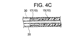
- FIG. 2 is a cross-sectional view taken along the line II-II of FIG. It is a detailed view of part IIIA of FIG. It is a detailed view of part IIIB of FIG. It is a detailed view of the IVA part of FIG. 3A. It is a detailed view of the IVB part of FIG. 3A. It is a detailed view of the IVC part of FIG. 3B. It is a detailed view of the IVD part of FIG. 3B.
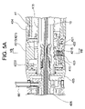
- FIG. 3 is a cross-sectional view showing a main part (VA part in FIG. 2) when the rotating body is in the first position in the stent delivery catheter device shown in FIG. 1.
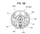
- FIG. 5A is a cross-sectional view taken along the line VB-VB of FIG. 5A.
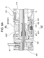
- FIG. 3 is a cross-sectional view showing a main part of the stent delivery catheter device shown in FIG. 1 when the rotating body is in the second position.
- FIG. 5A is a sectional view taken along line VIB-VIB of FIG. 5A.
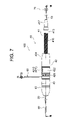
- FIG. 5 is a side view of the stent delivery catheter device shown in FIG. 1 when the movable grip is at the tip position of the moving range.
- FIG. 7 is a cross-sectional view taken along the line VIII-VIII of FIG. It is a detailed view of the IX part of FIG.
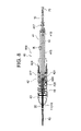
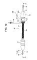
- FIG. 5 is a side view of the stent delivery catheter device shown in FIG.
- FIG. 10 is a cross-sectional view taken along the line XI-XI of FIG. It is explanatory drawing which shows the force which the inclined surface of a female thread formed on a rotating body presses the inclined surface of a male screw formed on a handle shaft, and the component force thereof.
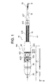
- the delivery catheter device 100 of this embodiment shown in FIGS. 1 to 11 is a catheter device for delivering a stent to a predetermined position in a lumen of a human body.
- An inner shaft 10 having a small tip diameter portion, an outer shaft 20 provided on the outside of the inner shaft 10 and movable in the axial direction with respect to the inner shaft 10, and an inner shaft 10 covered with the outer shaft 20 in a reduced diameter state.
- a handle 40 having a feed screw mechanism for moving the outer shaft 20 in the axial direction with respect to the inner shaft 10, a tip tip 50 connected to the tip side of the inner shaft 10, and a handle 40. Equipped with side injection pipe 60;
- the handle 40 is fixed to the inner shaft 10 to form a male screw 415 forming a feed screw mechanism, a fixed grip 43 fixed to the tip end side of the handle shaft 41, and an outer shaft 20.
- the movable grip 42 constituting the handle 40 has a long hole through which the handle shaft 41 is inserted, and a rotating body (nut member) in which a female screw 4215 forming a feed screw mechanism is formed only in one half circle portion of the long hole. ) 421, the rotating body case 422 that accommodates the rotating body 421, rotates around the handle shaft 41 together with the rotating body 421, and moves along the axial direction of the handle shaft 41 together with the rotating body 421, and the rotating body case 422.
- a spring 423 that is arranged inside and urges the male screw 415 of the handle shaft 41 to screw the female screw 4215 of the rotating body 421, and a rotation operation unit 424 fixed to the base end side of the rotating body case 422, and rotation.
- a slider 425 rotatably fixed to the rotating body case 422 and an outer shaft fixing portion 426 fixed to the slider 425 are provided;
- the rotating body 421 constituting the movable grip 42 has a first position in which the female screw 4215 is screwed with the male screw 415 of the handle shaft 41 and the female screw 4215 is not screwed with the male screw 415 of the handle shaft 41 inside the rotating body case 422.
- the movable grip 42 can be displaced along the radial direction of the handle shaft 41 to and from the second position;
- the movable grip 42 By rotating the rotating body 421 in the first position counterclockwise around the handle shaft 41 together with the rotating body case 422 and the rotation operation unit 424, the movable grip 42 is based on the axis of the handle shaft 41. Move towards the edge;
- the movable grip 42 By rotating the rotating body 421 in the first position clockwise around the handle shaft 41 together with the rotating body case 422 and the rotation operation unit 424, the movable grip 42 is directed toward the tip along the axis of the handle shaft 41.
- the outer shaft 20 can maintain the entire length of the stent 30 in a reduced diameter state, and when the movable grip 42 is at the rear end position of the movable range, the outer shaft 20 is used. The restraint can be completely released and the total length of the stent 30 can be increased;
- the rotation operation unit 424 is operated to rotate the rotating body 421 in the clockwise direction in which the movable grip 42 moves toward the tip, the urging force of the spring 423 is resisted.
- the rotating body 421 is displaced from the first position to the second position, and the screwing between the male screw 415 of the handle shaft 41 and the female screw 4215 of the rotating body 421 is released.
- 70 is a guide wire lure.
- the delivery catheter device 100 of the present embodiment includes an inner shaft 10, an outer shaft 20, a stent 30, a handle 40, a tip tip 50, and a side injection tube 60.
- the inner shaft 10 constituting the delivery catheter device 100 is a tube having a single lumen structure through which a guide wire can be inserted.
- the inner layer portion 11, the base end side outer layer portion 13, the tip end side outer layer portion 15, and the tip of the tip end side outer layer portion 15 are inner layers.
- the inner layer portion 11 is composed of an inner / outer layer fixing portion 17 to be fixed to the portion 11, and the inner layer portion 11 extending from the tip of the inner / outer layer fixing portion 17 constitutes a small diameter portion at the tip of the inner shaft 10.
- the inner layer portion 11 is made of a resin material such as PEEK resin.
- the inner diameter of the inner layer portion 11, which is the inner diameter of the inner shaft 10, is usually 0.4 to 1.1 mm, and a suitable example is 1 mm.
- the outer diameter of the inner layer portion 11, which is the outer diameter of the tip small diameter portion, is usually 0.8 to 1.5 mm, and a suitable example is 1.4 mm.
- the length of the inner layer portion 11 is usually 1000 to 1200 mm, and a suitable example is 1100 mm.
- the length of the tip small diameter portion from the tip of the inner / outer layer fixing portion 17 to the base end of the tip tip 50 is usually 40 to 140 mm, and a suitable example is 135 mm.
- the base end side outer layer portion 13 is made of a metal material such as stainless steel.
- the outer diameter of the base end portion of the inner shaft 10 formed by the base end side outer layer portion 13 is usually 2.4 to 3 mm, and a suitable example is 3 mm.
- the length of the base end side outer layer portion 13 is usually 400 to 500 mm, and a suitable example is 450 mm.
- the tip side outer layer portion 15 is made of a hard resin such as a polyacetal resin.
- the outer diameter of the tip portion of the inner shaft 10 formed by the tip side outer layer portion 15 is usually 3.3 to 4 mm, and a suitable example is 3.9 mm.
- the length of the tip side outer layer portion 15 is usually 400 to 600 mm, and a suitable example is 500 mm.
- the inner / outer layer fixing portion 17 is a cap for fixing the tip of the tip side outer layer portion 15 to the inner layer portion 11, and is made of a metal material such as stainless steel.
- the tip tip 50 is connected to the tip of the inner shaft 10 (inner layer portion 11).
- the base end portion of the handle shaft 41 is fixed to the inner shaft 10 (base end side outer layer portion 13).
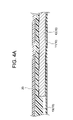
- the outer shaft 20 constituting the delivery catheter device 100 is movable in the axial direction with respect to the inner shaft 10.
- the outer shaft 20 is a tube having a single lumen structure made of a resin material.
- the resin tube constituting the outer shaft 20 is preferably reinforced by a blade, a coil, or the like.
- the inner diameter of the outer shaft 20 is larger than the outer diameter of the tip portion (tip side outer layer portion 15) of the inner shaft 10, and is usually 3.5 to 4.2 mm. For example, it is 4.2 mm.
- the outer diameter of the outer shaft 20 is usually 4 to 4.7 mm, and a suitable example is 4.7 mm.
- the length of the outer shaft 20 is usually 600 to 800 mm, and a suitable example is 680 mm.
- the base end of the outer shaft 20 is fixed to the slider 425 of the movable grip 42 via the outer shaft fixing portion 426 described later.
- the stent 30 constituting the delivery catheter device 100 is mounted on the tip small diameter portion of the inner shaft 10 in a reduced diameter state covered with the outer shaft 20.
- the proximal end of the stent 30 is in contact with or in close proximity to the tip of the inner / outer layer fixation portion 17, and the distal end of the stent 30 is in contact with or in close proximity to the proximal end of the tube 50.
- the stent 30 is self-expanding and has an outer shaft 20 at the position shown in FIG. 3B. By moving the stent 30 in the proximal direction with respect to the inner shaft 10, the stent 30 is released from the restraint by the outer shaft 20 and sequentially expands (deploys) in diameter.
- the "stent” includes a “stent graft”.
- the handle 40 constituting the delivery catheter device 100 includes a handle shaft 41 fixed to the inner shaft 10, a fixed grip 43 fixed to the tip end side of the handle shaft 41, and a movable handle fixed to the outer shaft 20. It is provided with a grip 42, and has a feed screw mechanism for moving the outer shaft 20 (movable grip 42) in the axial direction with respect to the inner shaft 10 (handle shaft 41).
- a male screw 415 forming a feed screw mechanism is formed on the handle shaft 41 constituting the handle 40. That is, the handle shaft 41 is a shaft member in the feed screw mechanism. As shown in FIG. 9, the male screw 415 is composed of a trapezoidal thread.
- the inclination angle ⁇ of the thread of the trapezoidal thread is preferably 110 ° or more (the angle ⁇ of the thread is 40 ° or more), and a suitable example is 115 ° (the angle ⁇ of the thread is 50 °). ..
- the inner shaft 10 extends inside the handle shaft 41, and the base end portion of the inner shaft 10 extends from the base end (base end side cap 417) of the handle shaft 41.
- the inner shaft 10 and the handle shaft 41 are adhesively fixed. Further, a fixed grip 43 is fixed to the tip end side of the handle shaft 41. As a result, the fixed grip 43 is fixed to the inner shaft 10 via the handle shaft 41.
- the movable grip 42 constituting the handle 40 moves along the axial direction of the handle shaft 41.
- the movable grip 42 includes a rotating body 421, a rotating body case 422, a spring 423, a rotation operating portion 424, a slider 425, and an outer shaft fixing portion 426.
- the rotating body 421 constituting the movable grip 42 is a tubular nut member having an elongated hole through which the handle shaft 41 is inserted.
- a female screw 4215 constituting a feed screw mechanism is formed in one semicircular portion of the long hole of the rotating body 421, and a female screw is formed in the other semicircular portion of the long hole of the rotating body 421. not.
- the diameter of the semicircular portion of the slotted hole is larger than the outer diameter of the male screw 415 of the handle shaft 41.
- the rotating body 421 rotates around the handle shaft 41 and moves along the axial direction, and is also movable in the radial direction of the handle shaft 41 by having an elongated hole.
- the rotating body 421 moves along the axial direction of the handle shaft 41 by the feed screw mechanism.
- the rotating body 421 when the female screw 4215 is not screwed with the male screw 415 (at the second position described later) can be freely moved along the axial direction of the handle shaft 41 by the manual operation of the operator.
- the rotating body case 422 constituting the movable grip 42 accommodates the rotating body 421, and the rotating body 4 is accommodated. Together with 21, it can rotate around the handle shaft 41 and move along the axial direction of the handle shaft 41.
- the spring 423 constituting the movable grip 42 is arranged inside the rotating body case 422, and the female screw 4215 of the rotating body 421 is screwed into the male screw 415 of the handle shaft 41 (the handle shaft 41 is formed on the rotating body 421). (To be located on one half-circle side of the slot).
- the rotation operation unit 424 constituting the movable grip 42 is fixed to the base end side of the rotating body case 422, rotates around the handle shaft 41 together with the rotating body 421 and the rotating body case 422, and rotates in the axial direction of the handle shaft 41. You can move along.
- the slider 425 constituting the movable grip 42 is rotatably fixed to the tip side of the rotating body case 422 with respect to the rotating body case 422. Since it is rotatable with respect to the rotating body case 422, even if the rotating body 421, the rotating body case 422, and the rotating operation unit 424 rotate integrally around the handle shaft 41, the slider 425 still has the handle shaft 41. It can move along the axial direction of the handle shaft 41 together with the rotating body 421, the rotating body case 422, and the rotating operation unit 424 without rotating around.
- the outer shaft fixing portion 426 constituting the movable grip 42 is fixed to the slider 425, and the base end of the outer shaft 20 is fixed. Further, a side injection pipe 60, which will be described later, is attached to the outer shaft fixing portion 426.
- the female screw 4215 is not screwed into the first position where the female screw 4215 is screwed into the male screw 415 of the handle shaft 41, and the female screw 4215 is not screwed into the male screw 415 of the handle shaft 41 inside the rotating body case 422.
- the handle shaft 41 can be displaced in the radial direction from the second position.
- the first position and the second position are relative positions of the rotating body 421 with respect to the rotating body case 422.
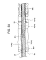
- 5A and 5B show a state in which the rotating body 421 is in the first position inside the rotating body case 422.
- the rotating body 421 When the rotating body 421 is in the first position, one semicircular side of the elongated hole formed in the rotating body 421 is located relative to the handle shaft 41, and the female screw 4215 formed in the one semicircular portion of the elongated hole. And the male screw 415 of the handle shaft 41 are screwed together. Therefore, when the rotating body 421 at the first position rotates around the handle shaft 41, the rotating body 421 is screwed and moves along the axial direction of the handle shaft 41.
- 6A and 6B show a state in which the rotating body 421 is in the second position inside the rotating body case 422.
- the rotating body 421 When the rotating body 421 is in the second position, the other semicircular side of the long hole formed in the rotating body 421 is located relative to the handle shaft 41, and the female screw 4215 formed in one semicircular portion of the long hole. And the male screw 415 of the handle shaft 41 are not screwed. Further, since the diameter of the semicircular portion of the slotted hole is larger than the outer diameter of the male screw 415 of the handle shaft 41, the rotating body 421 at the second position idles around the handle shaft 41 and the shaft of the handle shaft 41. Move along the direction.
- the rotating body 421 at the first position By rotating the handle shaft 41 in a "counterclockwise direction" together with the rotating body case 422 and the rotating body case 424, the movable grip 42 (rotating body 421, rotating body case 422, spring 423, rotating operating part 424). , The slider 425 and the outer shaft fixing portion 426) move in the proximal direction along the axis of the handle shaft 41.
- the movable grip 42 is attached to the axis of the handle shaft 41. Move toward the tip along.
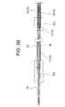
- FIG. 7 and 8 show the state when the movable grip 42 is at the tip position of the movable range. In this state, the tip of the movable grip 42 is in contact with the base end of the fixed grip 43, and the movable grip 42 cannot move to the tip side from this position.
- the outer shaft 20 covers the entire length of the stent 30, and the stent 30 is maintained in a reduced diameter state.
- the tip of the outer shaft 20 is located closer to the base end side than the base end of the stent 30, so that the restraint of the stent 30 by the outer shaft 20 is completely released. Therefore, the total length of the stent 30 can be increased.
- the rotating body 421 when such a malfunction is made, the rotating body 421 is displaced from the first position to the second position against the urging force of the spring 423, and the handle shaft 41 The male screw 415 and the female screw 4215 of the rotating body 421 are unscrewed.
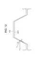
- the pressing force (F) toward the tip end by the inclined surface of the female screw 4215 has a component force (F 1 ) along the inclined surface.
- This component force (F 1 ) is a force that attempts to release the screw by separating the thread of the male screw 415 and the thread of the female screw 4215.
- the urging force of the spring 423 that opposes this force is adjusted to be relatively weak, so that the female screw 4215 and the male screw 415 are unscrewed against this urging force ( The rotating body 421 can be displaced from the first position to the second position).
- the urging force of the spring 423 is usually 3.5 to 14 N, preferably 10 to. 14N, a suitable example is 14N.
- the urging force of the spring 423 is 3.5 N or more, it is possible to secure an appropriate screwed state between the male screw 415 of the handle shaft 41 and the female screw 4215 of the rotating body 421. Further, since the urging force of the spring 423 is 14N or less, when the above-mentioned malfunction occurs, the rotating body 421 in the first position is surely placed in the second position against such urging force. Can be displaced to.
- the delivery catheter device 100 of this embodiment includes a button 4213 that manually displaces the rotating body 421 between the first position and the second position.
- the button 4213 is composed of a part of the rotating body 421 (a part facing the portion in contact with the spring 423 with the handle shaft 41 interposed therebetween), and the button 4213 can be pressed on the rotating body case 422.
- the opening 4223 is formed.
- the female screw 4215 formed in one semicircular portion of the long hole is not screwed with the male screw 415 of the handle shaft 41, and the diameter of the semicircular portion of the long hole is the handle. Since it is larger than the outer diameter of the male screw 415 of the shaft 41, the movable grip 42 provided with the rotating body 421 can be moved (sliding) along the axial direction of the handle shaft 41, and the movable grip can be moved without using the feed screw mechanism. By sliding the 42, the rapid diameter expansion operation of the stent 30 can be ensured.
- the stent 30 when the stent 30 is expanded (deployed) by the delivery catheter device 100 of this embodiment, first, the diameter is gradually expanded from the tip by using the feed screw mechanism of the male screw 415 and the female screw 4215. Then, it is preferable to displace the rotating body 421 from the first position to the second position by pushing the button 4213, and then slide the movable grip 42 to quickly deploy the rotating body 421.
- a tip tip 50 made of a soft resin material is connected to the tip end side of the inner shaft 10.
- the tip portion 50 of the inner shaft 10 (inner layer portion 11) is fixed to the inner shaft 10 by being inserted into the lumen of the tip tip 50.
- the tip of the outer shaft 20 is in contact with the base end portion of the tip tip 50.
- the delivery catheter device 100 includes a side injection tube 60 (flash port).
- the side injection pipe 60 is attached to the outer shaft fixing portion 426 of the movable grip 42, and moves along the axial direction of the handle shaft 41 together with the movable grip 42.
- the side injection pipe 60 can flush the liquid into the space surrounded by the outer circumference of the inner shaft 10 and the inner circumference of the outer shaft.
- the rotating body 421 when the rotating body 421 is in the first position and the movable grip 42 is in the tip position of the movable range, the operator rapidly rotates the rotation operation unit 424 in the clockwise direction. If a malfunction is performed, the rotating body 421 is displaced from the first position to the second position against the urging force of the spring 423, and the male screw 415 of the handle shaft 41 and the female screw of the rotating body 421 are displaced. Since the screw with the 4215 is released and the rotating body 421 spins around the handle shaft 41, an excessive load is applied to the male screw 415 and / or the female screw 4215 constituting the feed screw mechanism, or the rotating body 421 rotates together with the rotating body 421.
- the rotating operation unit 424 which is a moving component, does not fall off from the rotating body 421 and the rotating body case 422.
Landscapes
- Health & Medical Sciences (AREA)
- Engineering & Computer Science (AREA)
- Biomedical Technology (AREA)
- Cardiology (AREA)
- Oral & Maxillofacial Surgery (AREA)
- Transplantation (AREA)
- Heart & Thoracic Surgery (AREA)
- Vascular Medicine (AREA)
- Life Sciences & Earth Sciences (AREA)
- Animal Behavior & Ethology (AREA)
- General Health & Medical Sciences (AREA)
- Public Health (AREA)
- Veterinary Medicine (AREA)
- Media Introduction/Drainage Providing Device (AREA)
Priority Applications (3)
| Application Number | Priority Date | Filing Date | Title |
|---|---|---|---|
| PCT/JP2020/041830 WO2022101960A1 (ja) | 2020-11-10 | 2020-11-10 | ステントデリバリカテーテル装置 |
| JP2022561706A JPWO2022101960A1 (enExample) | 2020-11-10 | 2020-11-10 | |
| TW110129888A TW202218704A (zh) | 2020-11-10 | 2021-08-13 | 支架輸送導管裝置 |
Applications Claiming Priority (1)
| Application Number | Priority Date | Filing Date | Title |
|---|---|---|---|
| PCT/JP2020/041830 WO2022101960A1 (ja) | 2020-11-10 | 2020-11-10 | ステントデリバリカテーテル装置 |
Publications (1)
| Publication Number | Publication Date |
|---|---|
| WO2022101960A1 true WO2022101960A1 (ja) | 2022-05-19 |
Family
ID=81602389
Family Applications (1)
| Application Number | Title | Priority Date | Filing Date |
|---|---|---|---|
| PCT/JP2020/041830 Ceased WO2022101960A1 (ja) | 2020-11-10 | 2020-11-10 | ステントデリバリカテーテル装置 |
Country Status (3)
| Country | Link |
|---|---|
| JP (1) | JPWO2022101960A1 (enExample) |
| TW (1) | TW202218704A (enExample) |
| WO (1) | WO2022101960A1 (enExample) |
Citations (6)
| Publication number | Priority date | Publication date | Assignee | Title |
|---|---|---|---|---|
| JP2006511299A (ja) * | 2002-12-23 | 2006-04-06 | ボストン サイエンティフィック リミテッド | バルーンカテーテルと共に使用するための圧力解放装置 |
| JP2008543366A (ja) * | 2005-06-08 | 2008-12-04 | エクステント,インク. | 介入装置を操作及び制御するデバイス及び方法 |
| JP2013508080A (ja) * | 2009-10-20 | 2013-03-07 | ウイリアム エー クック オーストラリア ピィティワイ リミテッド | 回転制御式配備装置 |
| JP2013528112A (ja) * | 2010-06-08 | 2013-07-08 | ベニティ・インコーポレイテッド | 二方向ステント搬送システム |
| JP2014514013A (ja) * | 2011-03-01 | 2014-06-19 | エンドロジックス、インク | カテーテルシステムおよびその使用方法 |
| JP2014516676A (ja) * | 2011-05-12 | 2014-07-17 | メドトロニック,インコーポレイテッド | 微小移動およびマクロ移動制御装置を有する送達カテーテルシステム |
Family Cites Families (1)
| Publication number | Priority date | Publication date | Assignee | Title |
|---|---|---|---|---|
| US10321996B2 (en) * | 2015-11-11 | 2019-06-18 | Edwards Lifesciences Corporation | Prosthetic valve delivery apparatus having clutch mechanism |
-
2020
- 2020-11-10 JP JP2022561706A patent/JPWO2022101960A1/ja active Pending
- 2020-11-10 WO PCT/JP2020/041830 patent/WO2022101960A1/ja not_active Ceased
-
2021
- 2021-08-13 TW TW110129888A patent/TW202218704A/zh unknown
Patent Citations (6)
| Publication number | Priority date | Publication date | Assignee | Title |
|---|---|---|---|---|
| JP2006511299A (ja) * | 2002-12-23 | 2006-04-06 | ボストン サイエンティフィック リミテッド | バルーンカテーテルと共に使用するための圧力解放装置 |
| JP2008543366A (ja) * | 2005-06-08 | 2008-12-04 | エクステント,インク. | 介入装置を操作及び制御するデバイス及び方法 |
| JP2013508080A (ja) * | 2009-10-20 | 2013-03-07 | ウイリアム エー クック オーストラリア ピィティワイ リミテッド | 回転制御式配備装置 |
| JP2013528112A (ja) * | 2010-06-08 | 2013-07-08 | ベニティ・インコーポレイテッド | 二方向ステント搬送システム |
| JP2014514013A (ja) * | 2011-03-01 | 2014-06-19 | エンドロジックス、インク | カテーテルシステムおよびその使用方法 |
| JP2014516676A (ja) * | 2011-05-12 | 2014-07-17 | メドトロニック,インコーポレイテッド | 微小移動およびマクロ移動制御装置を有する送達カテーテルシステム |
Also Published As
| Publication number | Publication date |
|---|---|
| TW202218704A (zh) | 2022-05-16 |
| JPWO2022101960A1 (enExample) | 2022-05-19 |
Similar Documents
| Publication | Publication Date | Title |
|---|---|---|
| JP2017515610A (ja) | ステント送出システム | |
| JP4381818B2 (ja) | 医療用カテーテルの制御機構 | |
| CA2612914C (en) | Single peel stent introducer apparatus | |
| US3948251A (en) | Flexible tube endoscope | |
| US7004957B1 (en) | Actuating and locking mechanism for a surgical tool | |
| JP4294289B2 (ja) | 医療装置用のハンドル式配備機構および方法 | |
| US9265604B2 (en) | Device for use in delivery of ophthalmic lenses | |
| JP2019509135A (ja) | カム制御式多方向操向可能ハンドル | |
| CA2542362A1 (en) | Expandible surgical access device | |
| KR20080074759A (ko) | 내시경용 처치구 | |
| WO2022101960A1 (ja) | ステントデリバリカテーテル装置 | |
| CN113766890B (zh) | 支架递送装置 | |
| CN118450867A (zh) | 用于腔内假体的输送系统和使用方法 | |
| US20210299413A1 (en) | Torque device | |
| JP7385010B2 (ja) | ステントデリバリーシステム | |
| US20020082588A1 (en) | Laparoscopic applicator | |
| CN120787145A (zh) | 保持控制器 | |
| JP6313518B2 (ja) | 医療器具展開のためのハンドル | |
| EP3934588B1 (en) | Stent delivery system and handling device for a stent delivery system | |
| WO2018073957A1 (ja) | 処置具用回転機構 | |
| JPH1034406A (ja) | 中ぐり工具及び拡底孔の形成方法 | |
| JP6824104B2 (ja) | シャープペンシル | |
| JPWO2023107926A5 (enExample) |
Legal Events
| Date | Code | Title | Description |
|---|---|---|---|
| 121 | Ep: the epo has been informed by wipo that ep was designated in this application |
Ref document number: 20961488 Country of ref document: EP Kind code of ref document: A1 |
|
| ENP | Entry into the national phase |
Ref document number: 2022561706 Country of ref document: JP Kind code of ref document: A |
|
| NENP | Non-entry into the national phase |
Ref country code: DE |
|
| 122 | Ep: pct application non-entry in european phase |
Ref document number: 20961488 Country of ref document: EP Kind code of ref document: A1 |